


Robus P
Nice
RB500HS
RB600
RB1000
For sliding gates
EN - Instructions and warnings for installation and use


CONTENTS
GENERAL WARNINGS:
SAFETY - INSTALLATION - USE 2
1 - PRODUCT DESCRIPTION AND INTENDED USE 3
2 - OPERATING LIMITS 3
3 - INSTALLATION 4
4 - ELECTRICAL CONNECTIONS
4.1 - Types of electrical cables 10
4.2 - Electrical cable connections 10
5 - STARTING THE AUTOMATION AND CHECKING THE
CONNECTIONS
5.1 - Connecting the automation to the mains electricity 12
6 - TESTING AND COMMISSIONING
6.1 - Testing 12
6.2 - Commissioning 13
7 - PROGRAMMING
GLOSSARY 14
7.1 - Programming 14
7.2 - Level 1 functions (ON-OFF functions) 14
7.3 - Level 1 programming (ON-OFF functions) 15
7.4 - Level 2 functions (adjustable parameters) 16
7.5 - Level 2 programming (adjustable parameters) 17
7.6 - Recognition of devices 18
7.7 - Recognition of the gate length 18
7.8 - Checking gate movement 18
7.9 - Pre-set functions 19
7.10 - Radio receiver 19
8 - FURTHER DETAILS
8.1 - Adding or removing devices 19
8.2 - FT210B photosensor 20
8.3 - ROBUS in “Slave” mode 21
8.4 - Recognition of other devices 22
8.5 - Connecting the Oview programmer 22
8.6 - Special functions 22
8.7 - Connecting other devices 24
8.8 - Accessories 24
9 - DIAGNOSTICS 24
9.1 - Fault log list 25
9.2 - Diagnostics and signals 25
9.2.1 - Flashing light signals 25
9.2.2 - Control unit signals 26
10 - PRODUCT DISPOSAL 27
11 - MAINTENANCE 28
12 - TECHNICAL SPECIFICATIONS 28
CE DECLARATION OF CONFORMITY 29
User manual (end user version) 31
English – 1

GENERAL WARNINGS: SAFETY - INSTALLATION - USE (original instructions in Italian)
The following warnings are taken directly from the Regulations and apply, as far as possible, to the product described herein
CAUTION Important safety instructions. Observe all the instructions as improper installation may cause serious damage
CAUTION Important safety instructions. It is important to comply with these instructions to ensure personal safety. Store
these instructions
• Before commencing the installation, check the “Product technical specications”, in particular whether this product is suitable for automating
your guided part. Should it be unsuitable, DO NOT proceed with the installation
• The product cannot be used before it has been commissioned as specied in the “Testing and commissioning” chapter
CAUTION According to the most recent European legislation, the implementation of an automation system must comply with
the harmonised standards set forth in the Machinery Directive in force, which allow for declaring the presumed
conformity of the automation. On account of this, all operations regarding connection to the mains electricity, as
well as product testing, commissioning and maintenance, must be performed exclusively by a qualied and skilled
technician!
• Before proceeding with the product’s installation, check that all materials are in good working order and are suitable for the intended applications
• The product is not intended for use by persons (including children) with reduced physical, sensory or mental capacities, nor by anyone lacking
sufcient experience or familiarity with the product
• Children must not play with the appliance
• Do not allow children to play with the control devices of the product. Keep the remote controls out of reach of children
CAUTION In order to avoid any danger from inadvertent resetting of the thermal cut-off device, this appliance must not be powered
through an external switching device, such as a timer, or connected to a supply that is regularly powered or switched off by
the circuit
• Provide a disconnection device (not supplied) in the plant’s mains power supply, with a contact opening distance that ensures complete
disconnection under the conditions envisaged by Overvoltage Category III
• Handle the product with care during installation, taking care to avoid crushing, knocks, falls or contact with liquids of any kind. Keep the
product away from sources of heat and open ames. Failure to observe the above can damage the product and increase the risk of danger
or malfunctions. If this should happen, stop installation immediately and contact the Customer Service
• The manufacturer assumes no liability for damage to property, items or persons resulting from non-compliance with the assembly instructions.
In such cases the warranty does not cover material defects
• The weighted sound pressure level of the emission A is lower than 70 dB(A)
• Cleaning and maintenance to be carried out by the user must not be effected by unsupervised children
• Before intervening on the system (maintenance, cleaning), always disconnect the product from the mains power supply
• Check the system periodically, in particular all cables, springs and supports to detect possible imbalances, signs of wear or damage. Do not
use the product if repairs or adjustments are necessary, since an installation failure or an incorrectly balanced door may cause injury
• The packaging materials of the product must be disposed of in compliance with local regulations
• Keep persons away from the gate when it is moved through the control elements
• When performing a manoeuvre, keep an eye on the automated mechanism and keep all bystanders at a safe distance until the movement
has been completed
• Do not operate the automation if anyone is working on it; disconnect the power supply before permitting any work to be carried out
• If the power cable is damaged, it must be replaced by the manufacturer or by the latter’s technical assistance service, or by a similarly qualied
person, in order to prevent any type of risk
INSTALLATION PRECAUTIONS
• Prior to installing the drive motor, check that all mechanical components are in good working order and properly balanced, and that the au-
tomation moves correctly
• If the gate or door being automated has a pedestrian gate, then the system must include a control device that will inhibit the operation of the
motor when the pedestrian gate is open
• Make sure that the control devices are kept far from moving parts but nonetheless in a visible position.
Unless a selector is used, the control devices must be installed at a height of at least 1.5 m and must not be accessible
• That windows, having a gap exceeding 200 mm when open, are to be closed using a biased-off switch if the opening movement is controlled
by a re-sensing system
• Ensure that entrapment between the driven part and the surrounding xed parts due to the opening movement of the driven part is avoided
• Permanently x the label concerning the manual release adjacent to its actuating member
• After installing the drive motor, make sure that the mechanism, protective system and all manual manoeuvres operate properly
2 – English
PRODUCT DESCRIPTION AND INTENDED USE
1
ROBUS is a line of irreversible electromechanical gearmotors designed for automating sliding gates. These gearmotors are equipped with an
electronic control unit and a connector for the SMXI or OXI radio remote control receiver (both optional). Electrical connections to external devices are simplied thanks to use of the “BLUEBUS”, a technique that allows for connecting multiple devices with only 2 wires. ROBUS devices
work with electricity; in case of lack of power from the mains, it is possible to release them using a suitable key and manually move the gate or
use the optional accessory: PS124 back-up battery that allows for completing certain manoeuvres even when there is no mains power.
CAUTION! – Any use other than that specied herein or in environmental conditions other than those stated in this manual is to
be considered improper and is strictly forbidden!
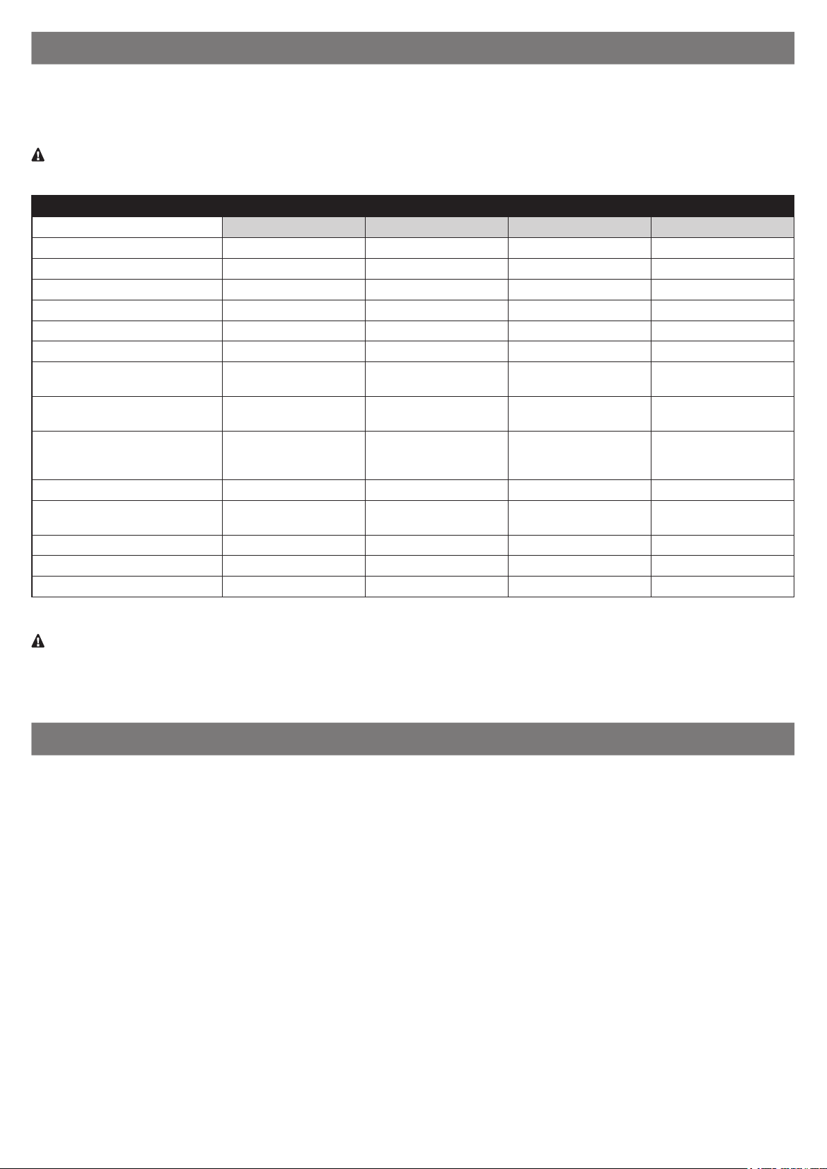
Table 1 - comparison of essential specications of ROBUS gearmotors
RB600 / RB600P RB1000 / RB1000P RB500HS RB500HS/V1
Gate length limit (m) 8 12 8 8
Weight limit (kg) 600 1000 500 500
Power supply (V) 230 230 230 120
Power draw (A) 2.5 2.3 2.2 4.2
Power (W) 515 450 460 460
Speed (m/s) 0.31 0.28 0.44 0.44
Maximum start-up torque (Nm)
corresponding to force (N)
Nominal torque (Nm) corresponding to force (N)
Cycles (cycles/hour)
- gate length up to 4 m
- gate length up to 8 m
IP protection rating 44 44 44 44
Ambient operating temperature
(°C)
Dimensions (mm) 330 x 212 x 303 h 330 x 212 x 303 h 330 x 212 x 303 h 330 x 212 x 303 h
Weight (kg) 11 13 11 11
Control unit RBA3 RBA3 RBA3/HS RBA3/HS
18
600
9
300
40
20
-20 ... +50 -20 ... +50 -20 ... +50 -20 ... +50
27
900
15
500
50
25
13
360
5,9
164
40
20
13
360
5,9
164
40
20
Note: 1 kg = 9.81 N (example: 600 N = 61 kg)
Caution! Any other use or use with dimensions greater than those specied is considered non-conforming. Nice declines all
liability for damage and injury resulting from non-conforming use.
APPLICATION LIMITS
2
The data relative to the performance of products of the ROBUS range are indicated in Chapter 12 “Technical specications” and are the only
values that allow for correctly assessing the product’s suitability for use.
The structural characteristics of ROBUS products make them suitable for use on sliding gates, according to the limits indicated in Table 2.
The actual suitability of ROBUS to automate a specic sliding gate depends on friction and on other factors, even occasional, such as the presence of frost, which may interfere with the gate’s movement.
For an actual verication it is absolutely vital to measure the force necessary to move the gate throughout its entire path and ensure that this
does not exceed half of the “nominal torque” indicated in Chapter 12 “Technical specications” (a 50% margin on the force is recommended, as
unfavourable weather conditions may cause friction to increase); furthermore, it is necessary to take into account the data indicated in Table 1
to establish the number of cycles/hour, consecutive cycles and maximum speed allowed.
Chapter 12 “Technical specications” contains the estimate of the product’s “durability”, that is, its average useful life. The durability value is
strongly inuenced by the severity of the manoeuvres, i.e. the sum of all factors that contribute to product wear. The estimate must be made by
summing up all the severity indices specied in Table 2; the total result can then be compared with the estimated durability gures in the chart.
For example, ROBUS 1000 mounted on a 650 kg gate that is 5 m long, equipped with photocells and without other intensity-enhancing elements, corresponds to a severity index of 50% (30+10+10). An estimated durability of 80,000 cycles can be inferred from the chart.
English – 3
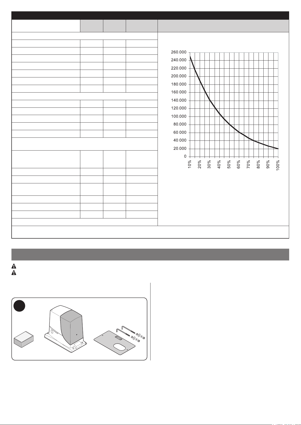
Table 2 - estimated durability in relation to the manoeuvre severity index
Severity index % RB600 RB1000 RB500HS
Gate leaf weight (kg)
Up to 200 10 5 30
200 – 400 30 10 40
400 – 500 50 20 60
500 – 600 - 30 -
600 – 800 - 40 -
800 – 900 - 50 -
900 – 1000 - 60 -
Gate leaf length (m)
Up to 4 10 5 15
4 – 6 20 10 25
6 – 8 35 20 35
8 – 10 - 35 -
10 – 12 - 50 -
Other factors contributing to fatigue
(to be considered if their probability exceeds 10%)
Ambient temperature greater
than 40°C or lower than 0°C, or
humidity greater than 80%
Presence of dust and sand 15 15 15
Presence of salinity 20 20 20
Manoeuvre interrupted by
photocell
Manoeuvre interrupted by Stop 25 20 30
Speed greater than “L4 fast” 20 15 25
Active peak force 25 20 25
Total severity index %:
Note: a severity index exceeding 100% implies that the conditions are beyond the limit of acceptability; in this case, a larger-size model is
recommended.
10 10 10
15 10 20
RB500HS/V1
Durability in cycles
Durability in cycles
Severity index %
INSTALLATION
3
Important! Before installing the product, refer to Chapter 2 and Chapter 12 (technical specications).
Vericare che la temperatura sia idonea all’ambito di applicazione.
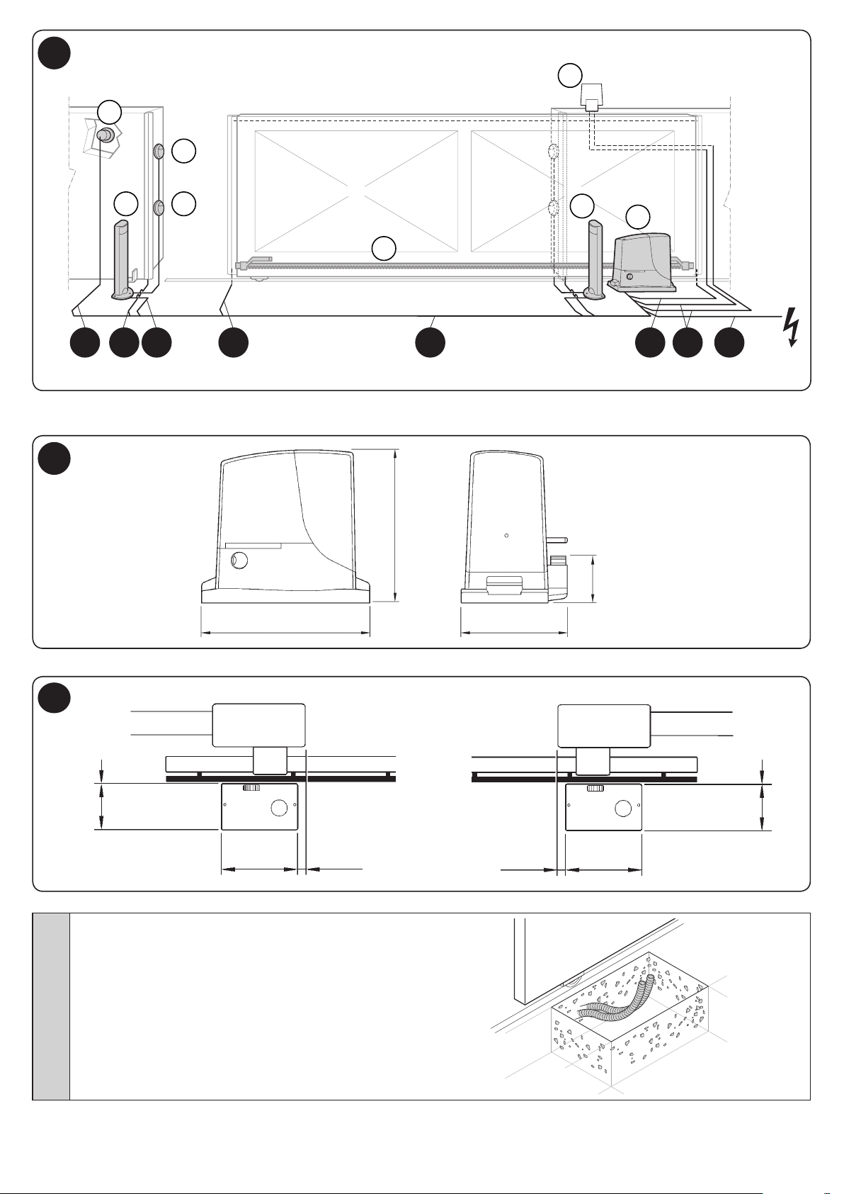
Fig. 1 shows the contents of the package: check that everything is
present and correct.
1
Fig. 2 shows the location of the various components of a typical installation with Nice accessories:
a - ROBUS gearmotor
b - photocells
c - posts for photocells
d - key selector / digital keypad
e - ashing light
f - rack
4 – English
D C BF AFE D
a
b
b
f
c
c
d
e
2
Before installing the system, check the gearmotor’s overall dimensions (Fig. 3) and installation measurements (Fig. 4):
3
330 mm
4
0 – 10 mm
192 mm
330 mm
01. Dig the foundation and arrange the tubes for the electrical
cables
0 – 50 mm
303 mm
212 mm
0 – 50 mm
92 mm
HS: 98 mm
0 – 10 mm
192 mm
330 mm
English – 5
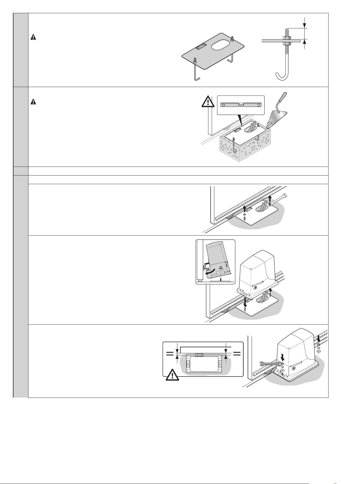
02. Secure the two anchor bolts to the foundation plate with
one nut above and one below the latter.
Tighten the lower nut in such a way that the upper
thread protrudes by roughly 25/35 mm.
03. Cast the concrete to secure the foundation plate.
Before the concrete hardens, make sure the
foundation plate is perfectly level and parallel to the
gate leaf.
04. Wait for the concrete to harden.
05. Secure the gearmotor:
a - remove the top nuts of the anchor bolts
25 – 35 mm
b - place the gearmotor on the anchor bolts: make sure
that it lies parallel with the gate leaf
c - insert the washers and nuts provided and tighten them
slightly
6 – English
d - adjust the gearmotor’s height by tightening the adjust-
g
1÷2 mm
g
1÷2 mm
g
g
er grub screws: position the pinion at the right height by
leaving a gap of 1–2 mm from the rack (this so as to prevent the gate leaf weight from bearing on the gearmotor)
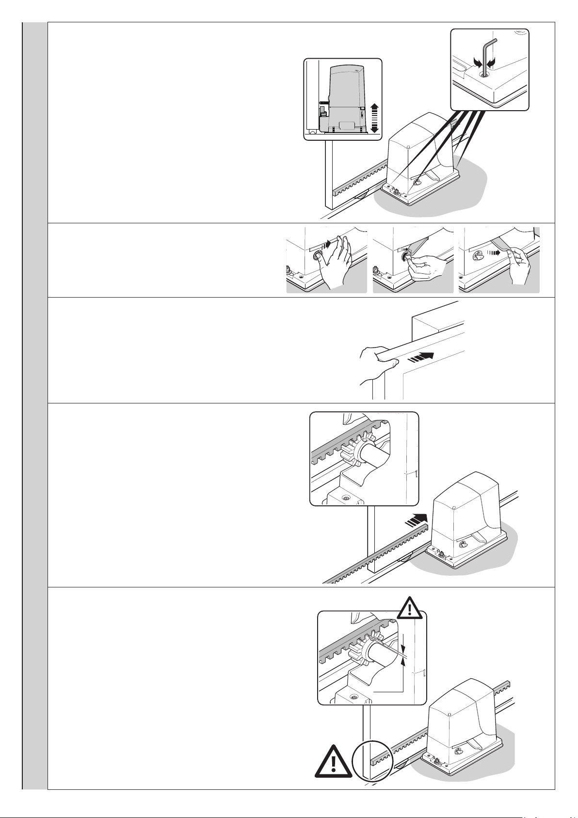
e / f / g - release the gearmotor
h - manually open the gate leaf fully
i - place the rst section of the rack on the gearmotor’s
pinion: make sure that it corresponds to the start of the
gate leaf and that there is a gap of 1–2 mm between the
rack and the pinion (this so as to prevent the gate leaf
weight from bearing on the gearmotor)
l - secure the rack section
1÷2 mm
English – 7
m - slide the gate by hand and, using the pinion as a refer-
1÷2 mm
g
h
1÷2 mm
g
ence, secure the other sections of the rack
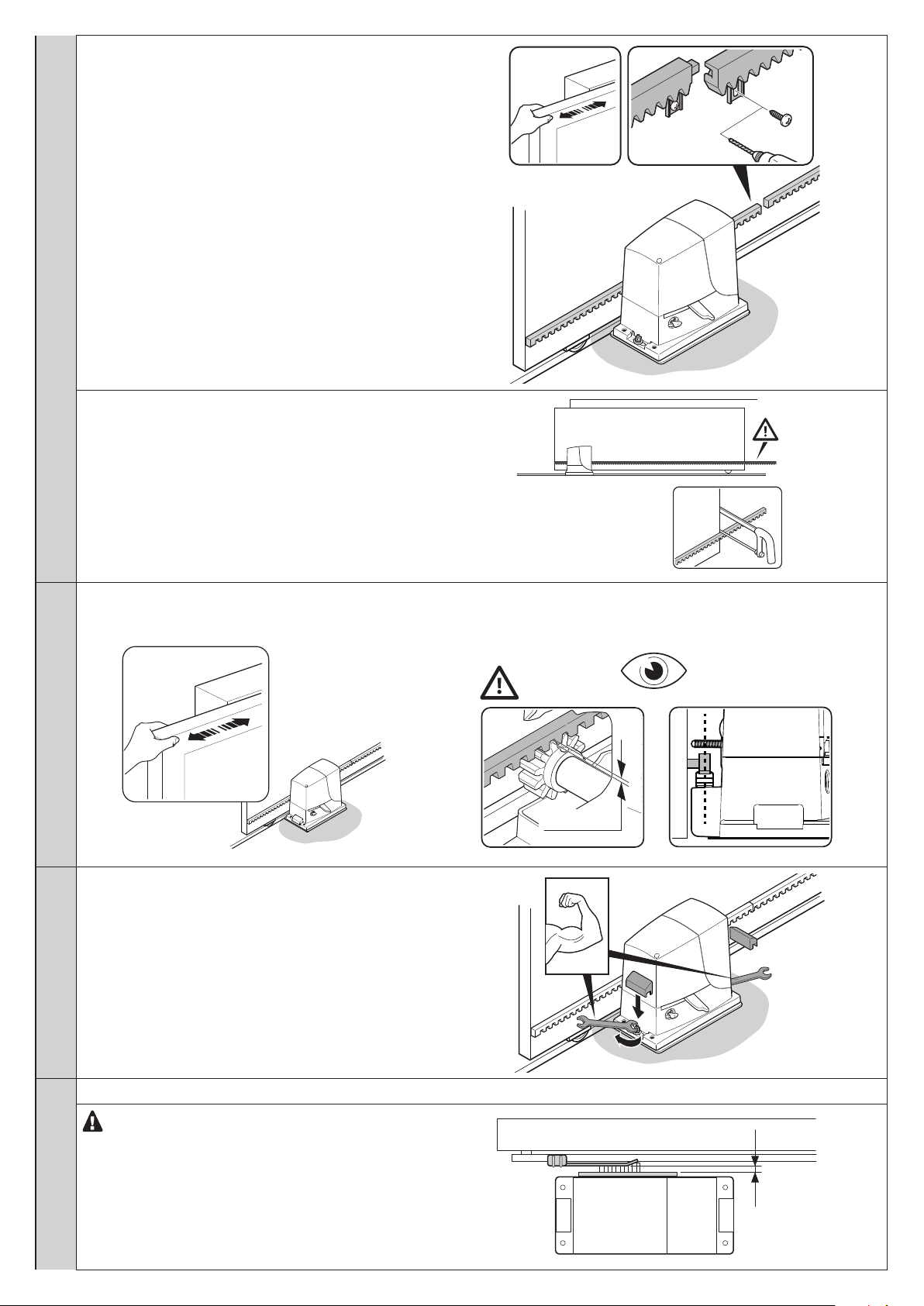
n - cut any excess rack off the end
06. Slide the gate open and closed by hand to check that the rack is properly aligned with the pinion.
N.B.: make sure that there is a gap of 1–2 mm between the rack and pinion for the entire length of the gate
1÷2 mm
07. Strongly tighten the nuts for xing the gearmotor to the
foundation plate and cover the nuts with the relevant caps
08. Secure the OPEN and CLOSE limit switch bracket: perform the same operations for both limit switches
For the RB600P and RB1000P versions with induc-
tive proximity limit switch, the optimal distance of the
bracket is between 3 and 8 mm
8 – English
3–8 mm
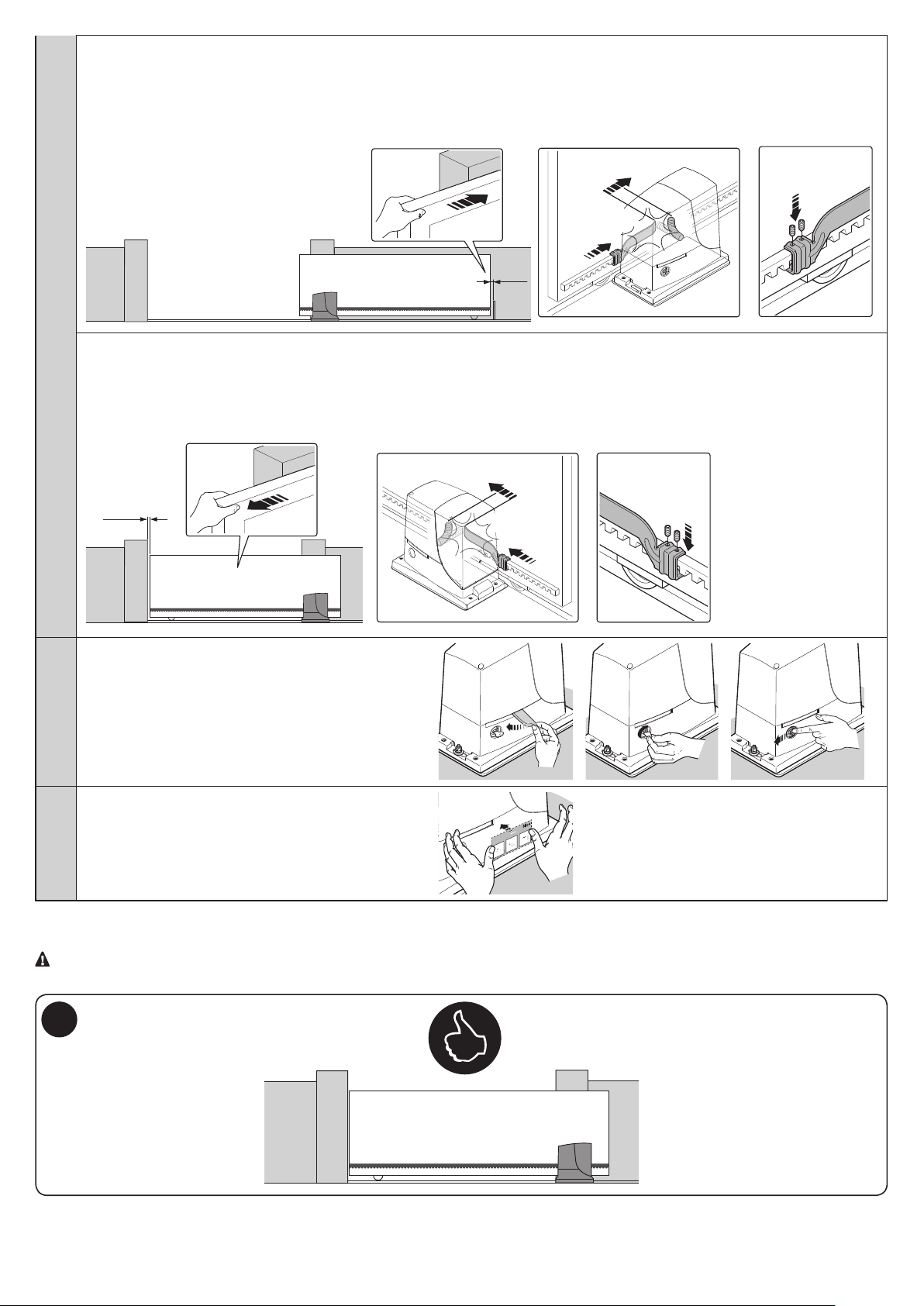
OPEN:
+2 cm
a - slide the gate leaf open by hand, stopping it 2/3 cm before the mechanical stop
b - slide the limit switch bracket along the rack in the open direction until the limit switch intervenes (a “click” will be heard)
c - after hearing the “click”, move the bracket further forward by 2 cm (minimum)
d - secure the bracket to the rack with the grub screws provided
+2 cm
click!
2-3 cm
CLOSE:
a - slide the gate leaf closed by hand, stopping it 2/3 cm before the mechanical stop
b - slide the limit switch bracket along the rack in the close direction until the limit switch intervenes (a “click” will be heard)
c - after hearing the “click”, move the bracket further forward by 2 cm (minimum)
d - secure the bracket to the rack with the grub screws provided
2-3 cm
click!
09. Manually lock the gearmotor
10. Apply the adhesive label showing the release instructions
Per Sbloccare - Pour débrayer - To unblock
Um zu entriegeln - Para desbloquear
Odblokowanie - Om te deblokkeren - Отпереть
1 2 3
To install the devices belonging to the system, refer to the respective instruction manuals.
IMPORTANT! – The gearmotor is congured (factory setting) for installation on the right-hand side (Fig. 5); to install it on the
left-hand side, perform the operations shown in Fig. 6.
5
English – 9
 Loading...