


Nice
OXIBD
OXIBD/A
Radio receiver
EN - Instructions and warnings for installation and use
made in Italy

EN
ENGLISH
Instructions translated from Italian
1 PRODUCT DESCRIPTION
OXIBD (OXIBD/A) is a radio receiver designed for being installed on a control unit for automating gates, garage doors and road barriers.
 – All uses other than the intended use described and use in environmental conditions other than those described in this manual should be considered improper and forbidden!
• One-way and two-way radio communication
In one-way radio communication, the two devices involved (equipped with one-way radio technology) have a clearly defined and unambiguous role within the system: there is a transmitter that simply transmits and a receiver that only receives without any further role. The radio communication, therefore, is one-way.
Instead in two-way communication, the two devices (equipped with two-way radio technology) play a different role each time within the system, as each one is capable of receiving and transmitting information from/to another device. Therefore, even the transmitters can turn into “receivers” of information coming from the receiver mounted in the control unit.
The OXIBD (OXIBD/A) receiver has both the radio technologies, thus it can interface with both one-way and two-way transmitters.
Throughout this manual, “two-way” refers to the “two-way technology” of receiver-transmitter radio devices, while the term “BD” denotes a specific radio encoding protocol adopted by OXIBD (OXIBD/A) and by transmitters featuring this encoding protocol.
“BD” encoding, unlike the other one-way encoding systems compatible with OXIBD (OXIBD/A) (see further below), offers the following additional functions:
1 - English

– the sending of the confirmation (on the transmitter) that the transmitted command was received; |
EN |
|
– the sending of the status (on the transmitter) of the transmitter (for example, if the door, gate, etc., is open or |
||
|
||
closed). |
|
• Other product characteristics
–The OXIBD receiver is compatible with the “O-Code”, “FloR”, “TTS”, “Smilo” and “Flo” one-way radio encoding systems, and with the “BD” two-way encoding system. In particular, the “O-Code” and “BD” encoding systems allow for exploiting all the advanced and exclusive functions of the “NiceOpera” system.
–The OXIBD/A receiver is compatible with the “O-Code/A”, “FloR/A” one-way radio encoding systems, and with the “BD” two-way encoding system.
–The receiver, if it contains one-way transmitters only, can manage 1024 memory locations at the most: one location can alternatively memorise a single transmitter (if its keys are memorised as a “single set”, with the Mode 1 procedures – read Paragraph 3.1), or a single key (if memorised with the Mode 2 procedures – read Paragraph 3.2). If the receiver contains two-way transmitters only, a maximum of 750 two-way transmitters can be memorised.
–Each receiver has its own identification number, known as the “Certificate”. This allows for accessing several operations, such as, for example: the memorisation of new transmitters without having to access the receiver, and the use of the O-View programmer through its “BusT4” connection to the control unit.
–This receiver can be used solely with control units equipped with “SM”-type plug connector (verify the most suitable control units on the Nice product catalogue or on the www.niceforyou.com website).
–This receiver automatically recognises the characteristics of the control unit on which it is installed and selfsets in the following way:
-If the control unit manages the “BusT4”, the receiver makes available up to 15 different commands.
-If the control unit DOES NOT manage the “BusT4”, the receiver makes available up to 4 different commands. Important! – In both cases, the number and diversity of the available commands depend on the type and
model of the control unit adopted. The “Table of commands” of each control unit is shown in the respective instruction manual.
English - 2

EN
2 INSTALLATION AND CONNECTION
The receiver must be connected to the control unit by inserting it through the relevant slot:
01. |
Before inserting (or removing) the receiver, |
|
OFF |
|
|
|
|
|
|
|
disconnect the power supply to the control unit. |
|
|
|
02. Connect the antenna supplied to terminal 1 of the re- |
|
|
|
|
|
ceiver, as shown in Fig. A. Alternatively, if the radio |
|
|
|
|
signal reception must be improved through the instal- |
2 |
|
|
|
lation of an external antenna with a coaxial cable with |
1 |
|
|
|
50Ω impedance (type RG58), the coaxial cable must |
|
2 |
1 |
|
|
|
||
|
be connected directly to terminals 1 and 2 of the |
Fig. A |
|
|
|
receiver (Fig. B), ignoring the “antenna” terminal (if |
|
||
|
present) on the control panel. |
|
|
|
03.Insert the receiver through the relevant opening on the control unit.
2 |
1 |
|
Fig. B
L2 |
L3 |
R |
3 - English
04. |
Restore the power supply to the control unit. |
ON |
|
|
|
EN
3 MEMORISING / DELETING TRANSMITTERS IN THE RECEIVER
The first one-way transmitter to be memorised in the receiver also defines the encoding system (“O-Code” (“O-Code/A”) or “FloR” or “TTS” or “Smilo” or “Flo”) that each successive one-way transmitter to be memorised must have. Transmitters with “BD” encoding can instead be memorised freely, as they are compatible with oneway transmitters inside the receiver’s memory.
Each single coding allows for exploiting only the functions linked to that specific encoding system.
To verify to which encoding system the transmitters already memorised in the receiver belong, proceed as follows (Warning! – The receiver must already be connected to the control unit):
Verification of the TYPE OF ENCODING system adopted by the transmitters already memorised
01. Disconnect the power supply to the control unit and then restore |
OFF ON |
|
the power. |
|
|
LED B of the receiver will light up green first then orange. When the |
|
|
orange LED switches off, count the number of subsequent flashes: |
|
|
•1 green flash = transmitters with O-Code or FloR or TTS encod- |
x 1 |
|
ing system |
||
|
||
•1 green flash and 1 orange flash = transmitters with O-Code or |
x 1+1 |
|
FloR or TTS + BD encoding system |
||
|
English - 4

EN
•2 green flashes = transmitters with O-Code (O-Code/A) or FloR |
x 2 |
|
or TTS encoding system |
||
|
||
|
|
•2 green flashes and 1 orange flash = transmitters with O-Code |
x 2+1 |
|
(O-Code/A) or FloR or TTS + BD encoding system |
||
|
•3 green flashes = transmitters with Smilo encoding system |
x 3 |
|
•3 green flashes and 1 orange flash = transmitters with Smilo + |
x 3+1 |
|
BD encoding system |
||
|
||
|
|
•5 green flashes = no transmitter memorised |
x 5 |
|
•5 green flashes and 1 orange flash = transmitters with BD tech- |
x 5+1 |
|
nology |
||
|
||
|
|
To change the coding assigned to the first one-way transmitter memorised, it is necessary to delete from the memory all the transmitters present (one-way and two-way), by strictly adopting Procedure 5 (Paragraph 3.6) and choosing the option, “ALL THE RECEIVER MEMORY”.
WARNINGS for carrying out the programming procedures |
A |
|
B |
• During the execution of the programming procedures, refer to Fig. 1 to identify key |
|
||
|
|
|
|
A and LED B on the receiver. • To understand the meaning of the icons featured in the |
|
|
|
procedure, refer to the table, “Key to the symbols used in the manual”. • The proce- |
|
2 |
1 |
|
|
|
|
dures have a limit time; therefore, before implementing them, it is important to read and |
|
|
|
understand all the steps to be completed. |
|
|
|
|
|
|
1 |
5 - English

|
|
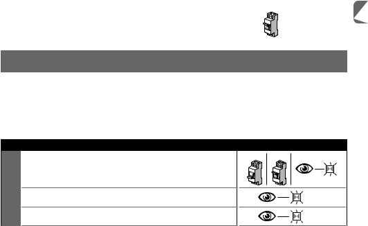
KEY TO THE SYMBOLS USED IN THE MANUAL |
Symbol |
Description |
|
|
|
(on the receiver) LED “B” STEADY LIT |
|
|
(on the receiver) LED “B” LONG FLASH |
|
|
(on the receiver) LED “B” QUICK FLASH |
|
|
(on the receiver) LED “B” OFF |
OFF |
ON |
|
|
|
Disconnect power supply / Restore power supply |
|
|
Wait ... |
> 5 sec < |
Perform the operation within 5 seconds ... |
|
|
|
Hold down key “A” of the receiver |
EN
English - 6

EN
Press and release key “A” of the receiver
Release key “A” of the receiver
Press and release the desired transmitter key
Hold down the desired transmitter key
Release the desired transmitter key
Read the control unit’s instruction manual


 ... Observe when LED “B” emits signals
The system can be programmed in Mode 1 or in Mode 2: see Paragraphs 3.1 and 3.2.
3.1 - Memorisation in “Mode 1”
While Procedure 1 is being carried out, the receiver memorises all the keys present on the transmitter, automatically assigning command 1 of the receiver to the 1st key, command 2 to the 2nd key, and so forth. Once the
7 - English
 Loading...