

Visual Systems
XT4100/5000/5100 Installation Data
Desktop and Ceiling Mount
Contents
Product Description, Lens Specs, Notes and Formulas Page 1
Projection Distances and Screen Sizes
Desktop Setup
Ceiling Mount Installation
Lens Shift Adjustable Range
TL-1Z, TL-2Z and TL-4Z Lens
TL-08SF Lens
Cabinet Dimensions
Front, Bottom & Left Side
Back, Top & Right Side
Lens Dimensions
Ceiling Mount Dimensions
RS232 Control
Command Codes
Connection
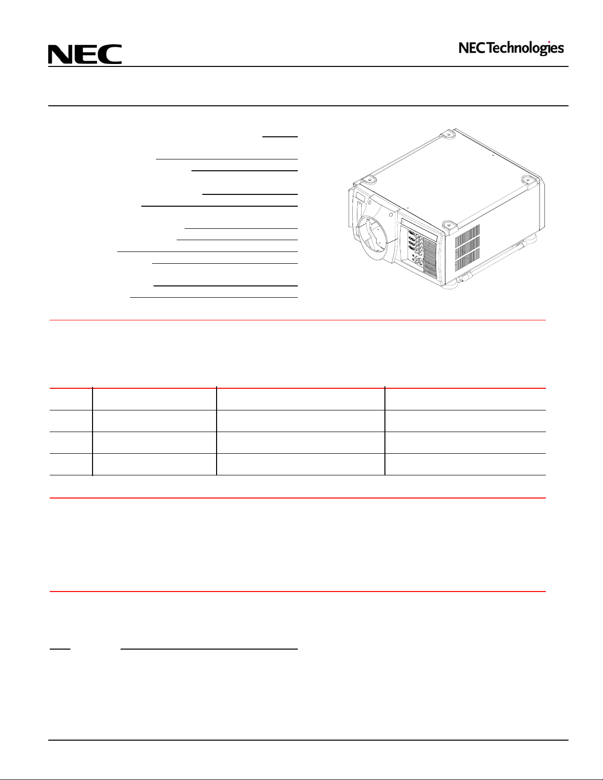
Product Description
Type: 3 chip, 0.9" DLP Dimensions: 22.05"(W) x 12.13"(H) x 26.85"(D) w/o lens
Native Resolution: 1024 x 768 Weight: 94.8 lbs
Brightness: XT4100: 3500 ANSI Lumens Power Lens Shift/Power Zoom/Power Focus
XT5000/5100: 4500 ANSI Lumens
Lens Specification
TL-08SF Throw Ratio: 0.84:1 F/#: 3.0 Distortion (full offset): 1% max
Screen Sizes: 80” - 500" Lateral color error: 14 µm max
TL-1Z Throw Ratio: 1.5 - 2.5:1 F/#: 3.0 Distortion (full offset): 2% max
Screen Sizes: 80" - 500" Lateral color error: 14 µm max
TL-2Z Throw Ratio: 2.5 - 4.0:1 F/#: 3.0 Distortion (full offset): 2% max
Screen Sizes: 80" - 500" Lateral color error: 14 µm max
TL-4Z Throw Ratio: 4.0 - 7.0:1 F/#: 3.0 Distortion (full offset): 2% max
Screen Sizes: 80” - 500" Lateral color error: 14 µm max
Notes
• For screen not indicated in the tables, use formulas below.
• If the figures in the tables do not match the results of formulas, use the figures in the tables.
• The ceiling must be strong enough to support the projector and the installation must be in accordance with any local building
codes.
• Distances are in inches, for millimeters multiply by 25.4
• Distances may vary ± 5%.
Formulas
Throw Distance = Screen Width (H) x Lens Magnification H = Screen Width H = Screen Height (V) x 4/3
Screen Diagonal = Screen Height (V) x 5/3
Lens Throw Distance Formula
TL-08SF: H x 0.84
TL-1Z: (Wide) = H x 1.5 (Tele) = H x 2.5
TL-2Z: (Wide) = H x 2.5 (Tele) = H x 4.0
TL-4Z: (Wide) = H x 4.0 (Tele) = H x 7.0
Ver 2.3
Page 2
Page 3
Page 4
Page 5
Page 6
Page 7
Page 8
Page 9
Page 10
Page 11
V = Screen Height V = Screen Width (H) x 3/4
Page1
Visual Systems
XT4100/5000/5100 Installation Data
Desktop and Ceiling Mount Ver 2.3
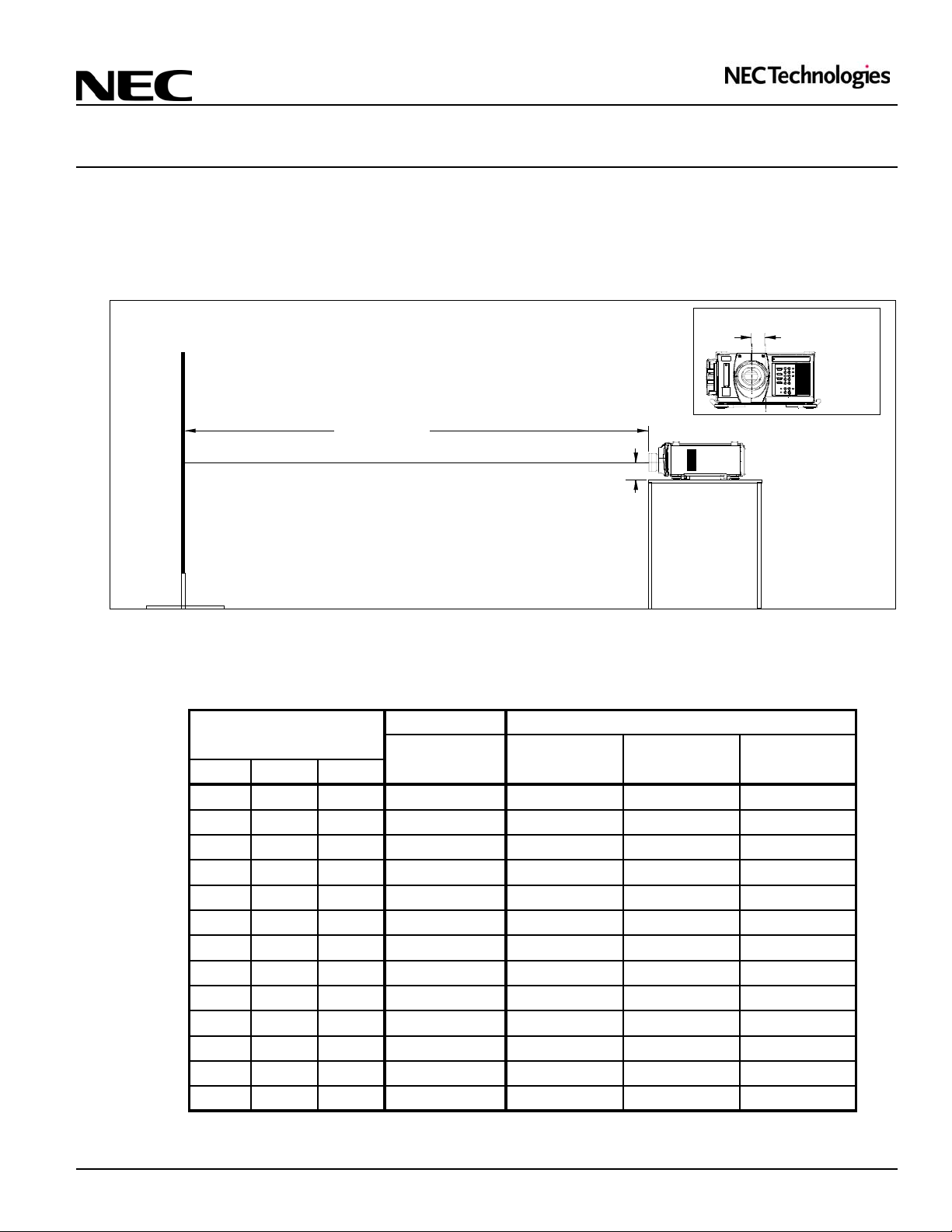
Projection Distance and Screen Size for No Offset Installation
The following shows the proper relative positions of the projector and screen.
Dimensions are in inches. For millimeters multiply by 25.4.
Desktop (no offset/optimum condition)
Lens Offset from
Projector Ctr
Screen Ctr
2.87"
Throw Distance
6.85"
Projection Distance
Image Size (4:3)
Diagonal Width (W) Height (V) 0.84:1 1.5 - 2.5 2.5 - 4.0 4.0 - 7.0
80" 64" 48" 53.8" 96" - 160" 160" - 256" 256" - 448"
100" 80" 60" 67.2" 120" - 200" 200" - 320" 320" - 560"
120" 96" 72" 80.6" 144" - 240" 240" - 384" 384" - 672"
150" 120" 90" 100.8" 180" - 300" 300" - 480" 480" - 840"
180" 144" 108" 121.0" 216" - 360" 360" - 576" 576" - 1008"
210" 168" 126" 141.1" 252" - 420" 420" - 672" 672" - 1176"
240" 192" 144" 161.3" 288" - 480" 480" - 768" 768" - 1344"
270" 216" 162" 181.4" 324" - 540" 540" - 864" 864" - 1512"
300" 240" 180" 201.6" 360" - 600" 600" - 960" 960" - 1680"
350" 280" 210" 235.2" 420" - 700" 700" - 1120" 1120" - 1960"
400" 320" 240" 268.8" 480" - 800" 800" - 1280" 1280" - 2240"
450" 360" 270" 302.4" 540" - 900 900" - 1440" 1440" - 2520"
500" 400" 300" 336.0" 600" - 1000" 1000" - 1600" 1600" - 2800"
Note: For screen sizes not indicated on the table, use formulas on Page 1
SF Fixed Lens Zoom Lens
TL-08SF TL-1Z TL-2Z TL-4Z
Page2
Visual Systems
XT4100/5000/5100 Installation Data
Desktop and Ceiling Mount Ver 2.3
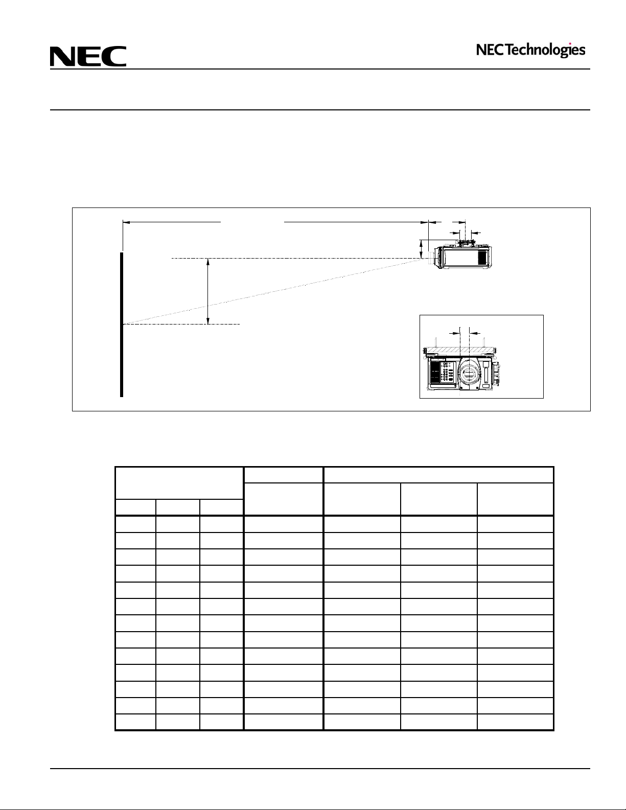
Projection Distance and Screen Size for Ceiling Mount/With Offset
The following shows the proper relative positions of the projector and screen. Refer to the table to determine the position of
installation.
Dimensions are in inches. For millimeters multiply by 25.4.
Ceiling Mount/With Offset
Throw Distance
9.75"
Vertical Offset
Screen Ctr
2.87"
X
5.12"
X = TL-08SF: 21.13"
TL-1Z: 17.36"
TL-2Z: 18.80"
TL-4Z: 19.01"
Lens Offset from
Ctr of Mount
Projection Distance
Image Size (4:3)
Diagonal Width (W) Height (V) 0.84:1 1.5 - 2.5 2.5 - 4.0 4.0 - 7.0
80" 64" 48" 53.8" 96" - 160" 160" - 256" 256" - 448"
100" 80" 60" 67.2" 120" - 200" 200" - 320" 320" - 560"
120" 96" 72" 80.6" 144" - 240" 240" - 384" 384" - 672"
150" 120" 90" 100.8" 180" - 300" 300" - 480" 480" - 840"
180" 144" 108" 121.0" 216" - 360" 360" - 576" 576" - 1008"
210" 168" 126" 141.1" 252" - 420" 420" - 672" 672" - 1176"
240" 192" 144" 161.3" 288" - 480" 480" - 768" 768" - 1344"
270" 216" 162" 181.4" 324" - 540" 540" - 864" 864" - 1512"
300" 240" 180" 201.6" 360" - 600" 600" - 960" 960" - 1680"
350" 280" 210" 235.2" 420" - 700" 700" - 1120" 1120" - 1960"
400" 320" 240" 268.8" 480" - 800" 800" - 1280" 1280" - 2240"
450" 360" 270" 302.4" 540" - 900 900" - 1440" 1440" - 2520"
500" 400" 300" 336.0" 600" - 1000" 1000" - 1600" 1600" - 2800"
Note: For screen sizes not indicated on the table, use formulas on Page 1
SF Fixed Lens Zoom Lens
TL-08SF TL-1Z TL-2Z TL-4Z
Page3
Visual Systems
XT4100/5000/5100 Installation Data
Desktop and Ceiling Mount Ver 2.3
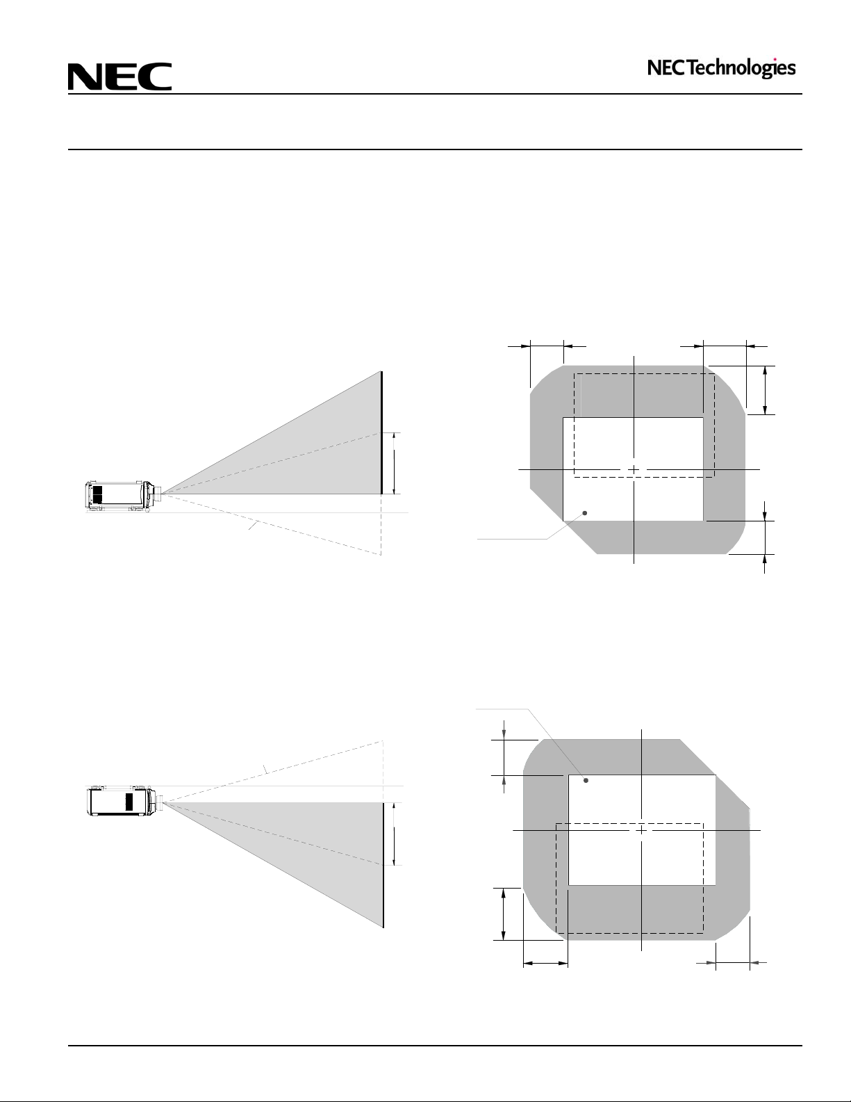
Lens Shift Adjustable Range
Lens Shift Adjustable Range for Desktop and Ceiling Mount Application.
The diagram below shows the location of the image position in the lens. The lens can be shifted within the shaded area as shown
using the normal projection position as a starting point.
Maximum Possible Range for TL-1Z, TL-2Z and TL-4Z
Maximum Possible Range:
Up: 0.5V
Down: 0.32V (only if image is shifted right first)
Right: 0.3H
Left: 0.23H (only if image is shifted up first)
Desktop/Front
Vertical
H: width of projected image
V: height of projected image
Max.
0.5V
0.23H
0.3H
0.5V
Normal Position
Note: There is a mechanical limitation to shift down without
first shifting right, and left without first shifting up. (Refer to
diagram)
Maximum Possible Range:
Up: 0.32V (only of image is shifted left first)
Down: 0.5V
Right: 0.23H (only if image is shifted down first)
Left: 0.3H
Ceiling/Front
Vertical
Normal Position
Normal projection
position
H: width of projected image
V: height of projected image
Normal projection
position
0.32V
Max.
0.5V
0.5V
0.32V
Note: There is a mechanical limitation to shift up without first
shifting left, and right without first shifting down. (Refer to
diagram)
0.3H
0.23H
Page4

Visual Systems
XT4100/5000/5100 Installation Data
Desktop and Ceiling Mount Ver 2.3
Lens Shift Adjustable Range (Cont.)
Lens Shift Adjustable Range for Desktop and Ceiling Mount Application.
The diagram below shows the location of the image position in the lens. The lens can be shifted within the shaded area as shown
using the normal projection position as a starting point.
Fixed Lens TL-08SF
Maximum Possible Range:
Up: 0.15V
Down: 0.15V
Right: 0.08H
Left: 0.08H
H: width of projected image
V: height of projected image
0.08H
0.08H
Desktop/Front
Vertical
Max. 0.15V
Normal Position
Note: There is a mechanical limitation to shift down without
first shifting right, and left without first shifting up. (Refer to
diagram)
Normal Projection
position
0.15V
0.15V
Note: To reduce the distortion of an image, it is recommended that the projector is horizontally positioned at a projection
angle of 0 degrees.
Page5

XT4100/5000/5100 Installation Data
Desktop and Ceiling Mount
Cabinet Dimensions
The following drawings show the cabinet dimensions for the XT4100/5000/5100.
Dimensions are in inches. For millimeters multiply by 25.4.
Ver 2.3
12.83
Visual Systems
6.85
5.55
18.11
4.33 10.08
1.971.97
1.18
12.444.92
M5 x 8
12.13
26.85
18.11
Page6

XT4100/5000/5100 Installation Data
Desktop and Ceiling Mount
Cabinet Dimensions (continued)
The following drawings show the cabinet dimensions for the XT4100/5000/5100.
Dimensions are in inches. For millimeters multiply by 25.4.
Ver 2.3
Visual Systems
1.40
19.92
2.13
Page7

XT4100/5000/5100 Installation Data
Desktop and Ceiling Mount
Lens Dimensions
The following drawings show the lenses mounted on the projector.
Dimensions are in inches. For millimeters multiply by 25.4.
Ver 2.3
9
1
.
8
Ø
TL-08SF 0.84:1 Fixed Lens
6.72
Visual Systems
1
9
.
5
Ø
TL-1Z 1.5-2.5:1 Zoom Lens
2.95
7
6
.
4
Ø
TL-2Z 2.5-4.0:1 Zoom Lens
4.39
2
7
.
4
TL-4Z 4.0-7.0:1 Zoom Lens
Ø
4.60
Page8

Visual Systems
XT4100/5000/5100 Installation Data
Desktop and Ceiling Mount Ver 2.3
Optional Ceiling Mount Dimensions
The following drawings show the dimensions of the Optional Ceiling Mount for XT4100/5000/5100 (Order Code XT-CMKIT).
Dimensions are in inches. For millimeters multiply by 25.4.
0.50
1.09
∅
0.312 (2x)
14.44
4.50
±3°
4.12
2.87
6.00
0.75
2.25
2.25
19.25
2.31
3.81 4.50 4.50 2.00
1.56
4.50
12.00
16.62
1.77
∅
4.504.50
15° (360° WITH PIPE) YAW, ±6° TILT
±3° ROLL
±6°
5.12
2.87
0.87
3.12
1.37
4.12
M6 (4X)
5.87
Page9

Visual Systems
XT4100/5000/5100 Installation Data
Desktop and Ceiling Mount Ver 2.3
RS232 Control / Command Codes
Standalone operation HEX CODE
POWER ON: 02 00 00 00 00 02
POWER OFF: 02 01 00 00 00 03
Input 1 RGB 1: 02 03 00 00 02 01 01 09
Input 2 RGB 2: 02 03 00 00 02 01 02 0A
Input 3 RGB 3: 02 03 00 00 02 01 03 0B
Input 4 COMPONENT: 02 03 00 00 02 01 12 1A
Input 5 VIDEO 1: 02 03 00 00 02 01 06 0E
Input 6 VIDEO 2: 02 03 00 00 02 01 07 0F
Input 7 S-VIDEO 1: 02 03 00 00 02 01 0B 13
Input 8 S-VIDEO 2: 02 03 00 00 02 01 0C 14
Input 9 RGB DIGITAL: 02 03 00 00 02 01 1A 22
Input 0 SDI: 02 03 00 00 02 01 1B 23
PICTURE MUTE ON: 02 10 00 00 00 12
PICTURE MUTE OFF: 02 11 00 00 00 13
DISPLAY MUTE ON: 02 14 00 00 00 16
DISPLAY MUTE OFF: 02 15 00 00 00 17
LENS SHUTTER ON: 02 16 00 00 00 18
LENS SHUTTER OFF: 02 17 00 00 00 19
LAMP AUTO: 03 88 00 00 02 0B 00 98
HIGH-BRIGHT: 03 88 00 00 02 0B 01 99
VARIABLE: 03 88 00 00 02 0B 02 9A
PICTURE
BRIGHT 03 10 00 00 05 00 FF 00 Lower Upper CKS
Adustment Value from FFE1(min) to 001F(max).
CONTRAST 03 10 00 00 05 01 FF 00 Lower Upper CKS
Adustment Value from FFE1(min) to 001F(max).
COLOR 03 10 00 00 05 02 FF 00 Value 00 CKS
Adustment Value from 00(min) to 5F(max).
HUE 03 10 00 00 05 03 FF 00 Value 00 CKS
Adustment Value from 00(min) to 3C(max).
SHARPNESS 03 10 00 00 05 04 FF 00 Value 00 CKS
Adustment Value from 00(min) to 0F(max).
V-APERTURE 03 10 00 00 05 1D FF 00 Value 00 CKS
Adustment Value from 00(min) to 0F(max).
Lower : Lower byte of Value, Upper : Upper byte of Value
CKS : Check Sum
Lower eight bits digits of sum total of the first byte to the byte just before the last.
The unit address is not checked when the unit ID has become a general notification.
Please set "0" to the unit ID and set "00" to the unit address when you use the projector under the standalone mode.
Page10

Visual Systems
XT4100/5000/5100 Installation Data
Desktop and Ceiling Mount Ver 2.3
RS232 Control / Connection
Cable Connection
Communication Protocol
Baud rate: 4800/9600/19200/38400 bps (selectable)
Data length: 8 bits
Parity: No parity
Stop bit : 1 bit
X on/off: None
Communication procedure: Full duplex
Note: For cable lengths longer than 20’, it is recommended changing baud rate to 9600 bps.
PC Control Connector (D-Sub 9P)
To TxD of PC To RxD of PC
To GND of PC
1234
67
To CTS of PC
Note: Jumper "Request to Send" and "Clear to Send" together on both ends of the cable to simplify cable connection.
5
8
9
To RTS of PC
Page11
 Loading...