


12345
6
6
6
6
6
12345
12345
12345
12345
INTRODUCTION.
Before operating this projector, please read this manual carefully and completely.
This manual will provide you with the basic instructions for operation of the
projector. Installation, preliminary adjustments and procedures which require the
opening of the projector and contact with electrical components should be
performed by service personnel. For continued safe and reliable operation, use
only cables supplied by the manufacturer for power. Adhere to all notes and
warnings.
Features
© Multi scan circuit automatically locks on video, superdata from 15 to 85 kHz
(XG85) and graphics signals 15 to 135 kHz (XG135LC).
You can interface video and high resolution RGB signals from various
computers, workstations and graphics boards.
© 8" CRTs with deflection angle 90 degrees produce a detailed picture with a
resolution of 250022000 (addressable) XG135LC and 160021200 (addressable) XG85.
© Newly developed video output circuit makes possible 110 MHz of Video
Bandwidth (XG85) and 150MHz (XG135LC) with 1100 lumens peak light
output (XG85) and 1200 lumens (XG135LC).
© ECP lens produces an image with true color reproduction.
© AKB circuit provides stable white balance.
© Display size can be altered to accommodate any picture size from 60" to 300"
diagonal. In addition to ceiling mounting, floor, desk top and rear installations
are possible. (The ceiling mounting kits can be purchased as an optional item
for ceiling installation.)
© Digital convergence provides high accuracy for projecting fine graphic
displays.
© On-screen menus provide easy access to adjustment items.
© ISS-6020/ISS-6020G interface allows 100 inputs.
© Video system compatible with NTSC, PAL, SECAM and NTSC 4.43.
© Up to 100 sources can be stored in digital memory.
© Quick copy convergence for fast easy set up from one pre-set signal.
© Built in self diagnostics for on-sight troubleshooting.
© Built in test patterns such as “CROSS HAIR”, “CROSS HATCH”, “DOT”,
“WINDOW” ,“ALL WHITE”, “GRAY SCALE”, and “H (FOCUS)” for
accurate setup.
© Source information status display.
© The SEQUENCER function allows the projector to automatically select input
signals one after another as programmed by the user.
© Compatible with a component video signal such as DVD.
3

INTRODUCTION
Important Safeguards
The following are important safety instructions designed to ensure the long life
of your projector and to prevent fire and shock hazards. Be sure to read these
safety instructions carefully and follow all warnings given below.
Installation
The projector must be installed by trained personnel.
Place the projector on a flat, level surface and in a dry area free from dust and
moisture. Do not place the projector in direct sunlight, near stoves or other heat
radiating appliances. Smoke, steam and exposure to direct sunlight could adversely affect the internal components. Avoid rough handling when moving your
equipment as a strong shock could damage its internal components. If installing
the projector on the ceiling, use only optional ceiling kits (two types) supplied by
the manufacturer. Observe all instructions and warnings. Since installing the
projector on the ceiling requires special techniques and a optional ceiling kit,
users must not try to install it. Contact your dealer for ceiling installation.When
ordering the ceiling kit, specify the part name, PG CMKIT-F or PG CMKIT.
Power supply
The XG-852 and XG-1352 projector are designed to operate on 120 V 60 Hz, and
the XG-852G and XG-1352G are designed to operate on 220-240 V 50 Hz AC
power supply. Make sure your local power supply matches these requirements
before operation.
Handle the power cord carefully and avoid excessive bending. A damaged cord
may cause electric shock or fire. If the projector is not to be used for an extended
period, remove the plug from the power outlet.
Cleaning
Unplug the projector from the power outlet before cleaning.
Clean the cabinet and front panel periodically with a soft cloth. If heavily stained,
use a mild detergent solution. Never use strong detergents or solvents such as
alcohol or thinner to clean your projector.
Lens cleaning: Avoid touching the lens surfaces.
Special coating is applied to the lens surfaces.
Consult your dealer for lens cleaning.
Fire and Shock Precautions
Adequate ventilation must be provided to prevent heat build-up inside the
projector. Make sure the ventilation holes are unobstructed.
Keep the inside of the projector free from foreign objects, such as paper clips,
nails, paper, etc. Do not attempt to retrieve such objects yourself or insert metal
objects such as wire and screw-drivers inside the projector. If a hazardous object
falls inside the projector, unplug it immediately and call a qualified electrical
repairman for removal.
Do not set liquids on top of the projector.
4
12345
6
6
6
6
12345
12345
12345
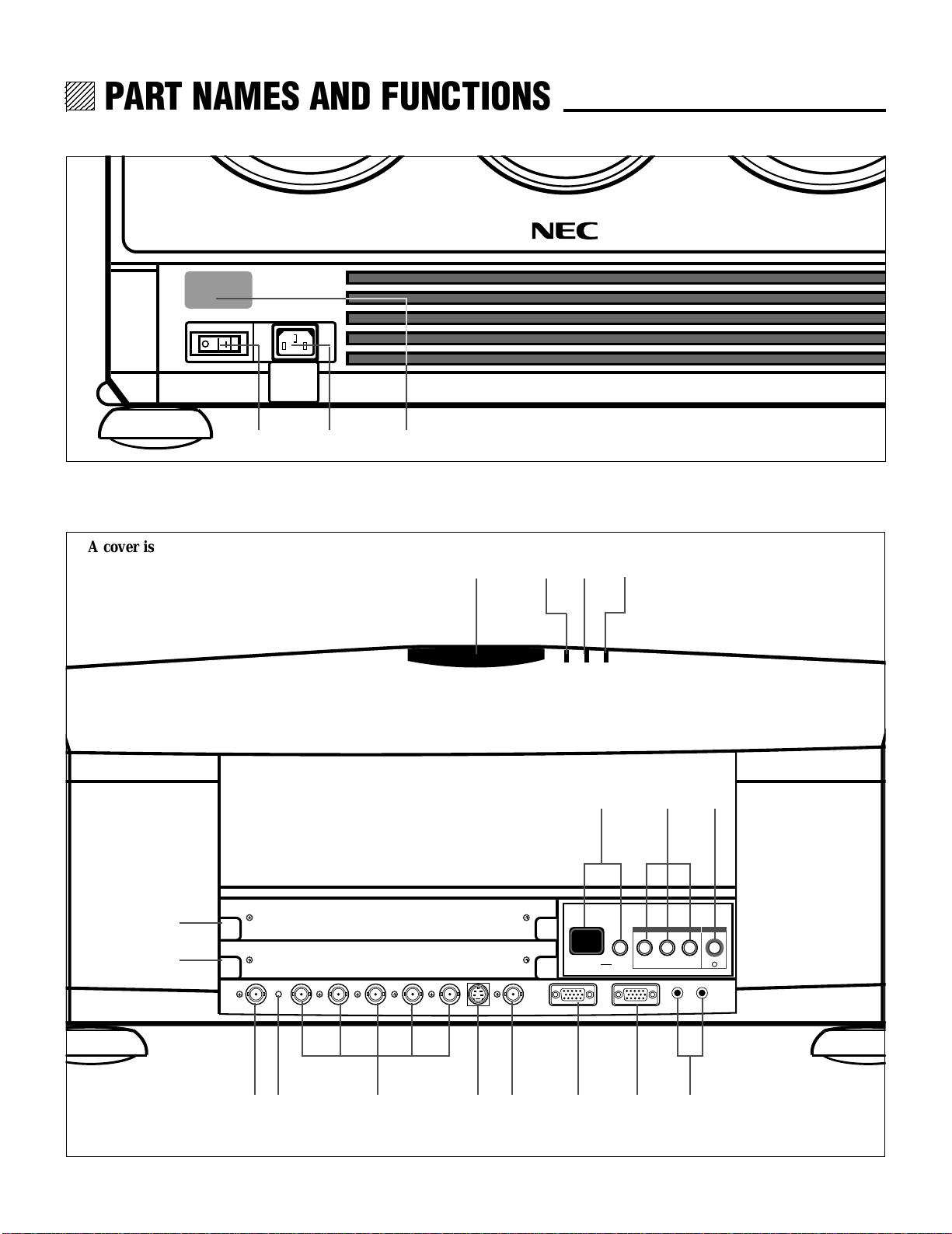
PART NAMES AND FUNCTIONS
PART NAMES AND FUNCTIONS.
Front Terminal Panel
1 32
Rear Control Panel
A cover is provided to attach the rear control panel.
I
H
4 65 7
89
INPUT SELECT POWER
INPUT SELECT ENTERON/OFFINDICATOR
0
I
ACAT OUT R/Cr G/Y B/Cb H/HV V S-VIDEO VIDEO OPTION REMOTE1 REMOTE2
J
A
4
OUT IN
GFEDCB
12345
6
6
6
6
6
12345
12345
12345
12345
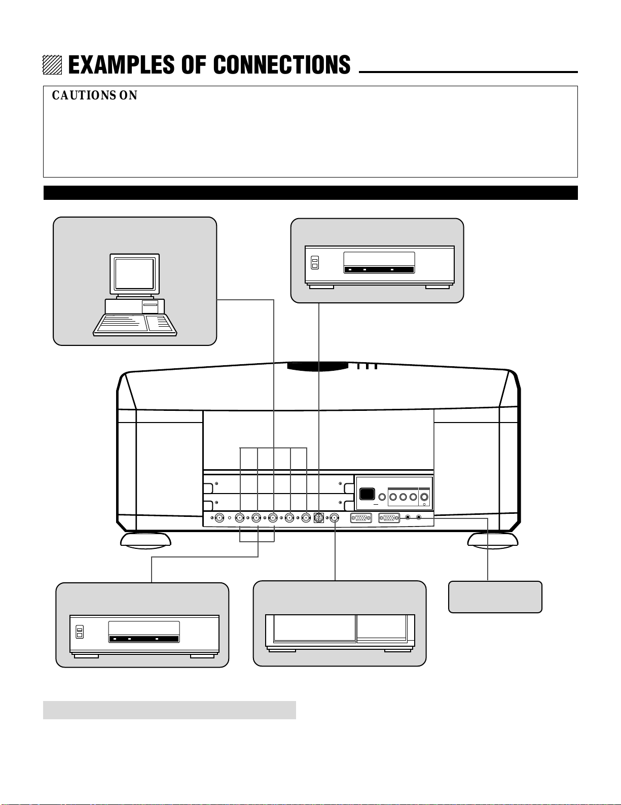
EXAMPLES OF CONNECTIONS.
CAUTIONS ON CONNECTIONS:
• Unplug the projector and other equipment from the AC
supply before making connections.
• Make sure that the plug of the power cord is properly
connected to the power outlet. A loose connection may cause
hum or noise.
When Used in Stand Alone Operation
•Confirm your connection layout with the user’s manual
accompanying the equipment to be connected with the ISS6020/ISS-6020G Switcher.
Components with RGB and H/V SYNC
outputs such as a personal computer
VCR with S-Video outputs
INPUT SELECT POWER
INPUT SELECT ENTERON/OFFINDICATOR
ACAT OUT R/Cr G/Y B/Cb H/HV V S-VIDEO VIDEO OPTION REMOTE1 REMOTE2
OUT IN
I
DVD Player with a COMPONENT video
output
VCR or Video disc player
External Control
NOTE: This projector does not have built-in speakers.
• Make sure that the STANDALONE mode is selected from the CONNECT CONDITION menu. Contact your dealer for the
information in detail.
10
12345
6
6
6
6
12345
12345
12345
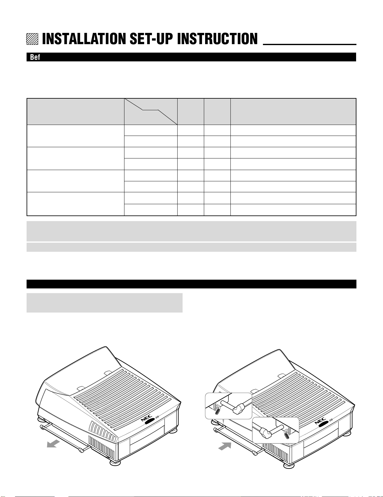
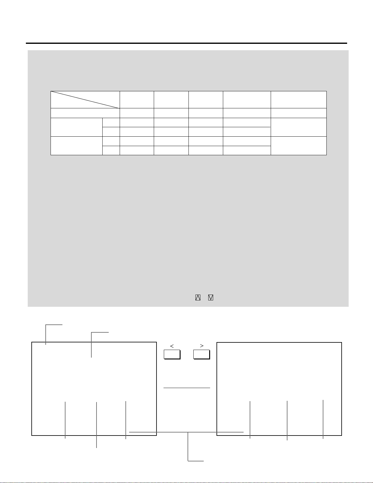
INSTALLATION SET-UP INSTRUCTION.
Before Installation
The installation procedure is different according to the projection system and screen size. From the factory the projector is set for
ceiling mount, 100 inch diagonal screen size and a projection angle of 12.4 degrees (XG85)/12.2 degrees (XG135LC).
Installation and preliminary adjustments are required as shown on table below.
Adjustment
Projection type
Ceiling mounting Front projection
Desk top Front projection type
Ceiling mounting/Rear projection
Desk top Rear projection
Screen size
items
(diagonal)
100 inch
other than 100 inch
100 inch
other than 100 inch
100 inch
other than 100 inch
100 inch
other than 100 inch
Various
adjustments
None
Yes
Yes
Yes
Yes
Yes
Yes
Yes
H Polarity
change
None
None
Yes
Yes
Yes
Yes
None
None
Focus ring and CRT angle change
None (
Set the focus ring when changing projection angle
Yes
None (
Set the focus ring when changing projection angle
Yes
et the focus ring when changing projection angle
None (S
Yes
None (
Set the focus ring when changing projection angle
Yes
NOTE: For XG85, the “100 inch” covers the range of screen size between 80 and 129 inches. For XG135LC, The ''100 inch'' covers
the range of screen size between 90 and 109 inches.
NOTE: Focus ring adjustment on pages 15 and 16 for XG85, and 17 and 18 for XG135LC.
)
)
)
)
Carrying the Projector
WARNING:
Be sure to use the handles when carrying the projector.
Pulling Out the Handle
Pull out the handle from the bottom side.
Retracting the Handle
Press down the two levers at the same time to retract the
handle.
3

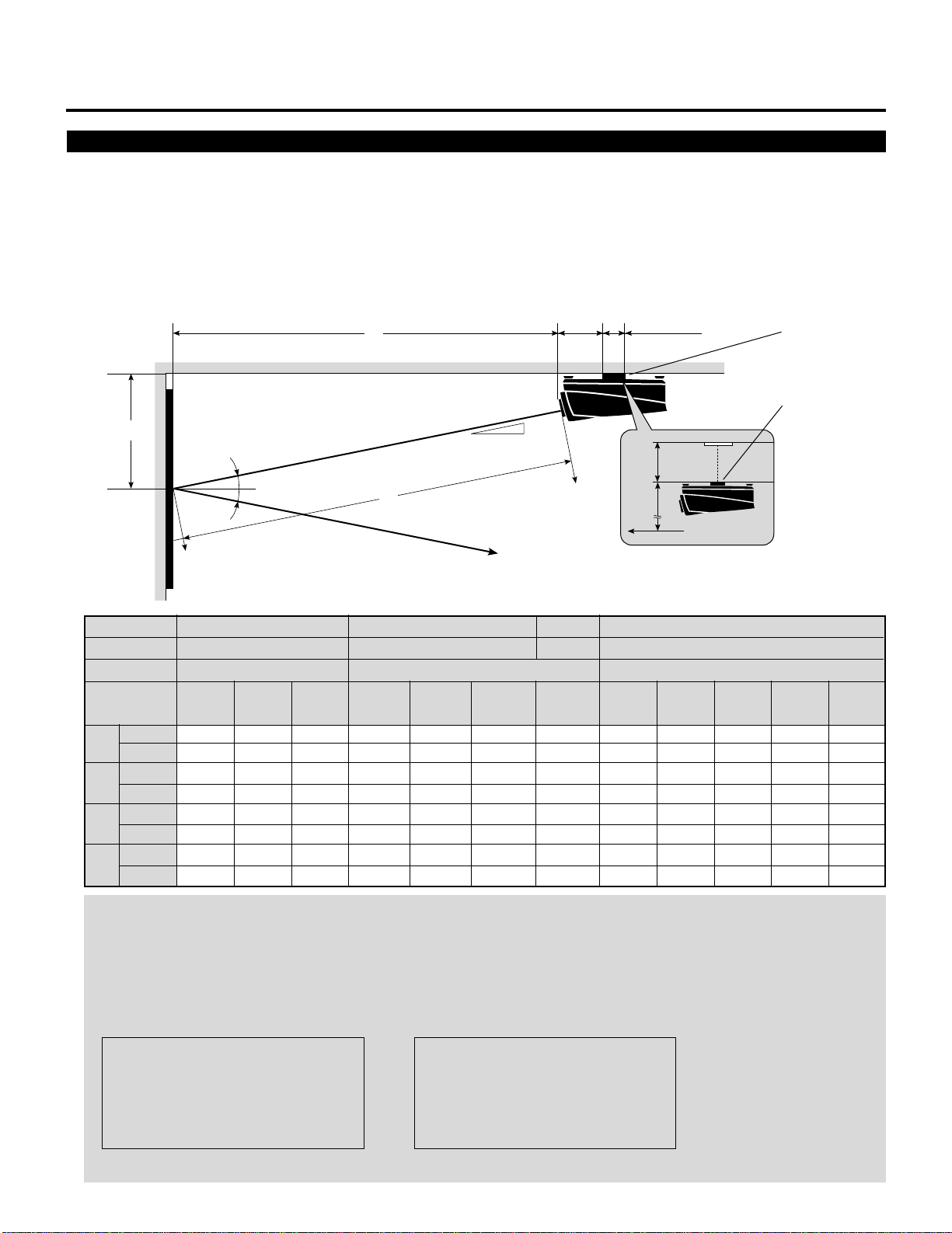
INSTALLATION SET-UP INSTRUCTION
Ceiling Mount Projection Distance and Screen Size for XG85
•
Install in such a way that the projector and screen are positioned in the proper direction and at the proper angle. If not, the projector's
performance will be affected and its reliability will decrease. Be sure to position the projector properly.
The manufacturer will not be held responsible for any problems occurring when the projector is not installed in the proper position.
The following shows the proper relative positions of the projector and screen. Refer to the table to determine the position of
installation
Ceiling Mount System
B
Screen center
α
β (=sinα)
γ (=cosα)
Screen size H-Width
(4:3 Diagonal)
inch
A
mm
inch
B
mm
inch
C
mm
inch
E
mm
48"
(60")
70.28
1785
26.00
661
68.72
1746
–
–
α
α
56"
(70")
81.54
2071
28.36
721
79.73
2025
–
–
64"
(80")
91.6
2318
30.86
784
89.13
2264
–
–
C
A
72"
(90")
101.74
2584
33.11
841
99.36
2524
–
–
80"
(100")
112.68
2862
35.46
901
110.05
2796
–
–
Line of sight
96"
(120")
133.43
3389
39.91
1014
130.32
3310
–
–
α
11.15"
(283mm)
120"
(150")
164.69
4183
47.19
1199
160.72
4083
–
–
5.12"
(130mm)
144"
(180")
196.11
4981
54.38
1381
191.31
4860
–
–
E
B
Screen center
0.9760.9770.978
160"
(200")
214.02
5436
58.31
1481
208.78
5303
1.69
43
12.7°12.6°12.4°12.1°
0.2200.2180.2150.210
192"
(240")
258.51
6566
68.10
1730
252.18
6406
3.91
100
Ceiling Mounting
Ceiling Mounting
When using a screen 150"
(3810mm) or larger (in the
diagonal direction)
216"
(270")
290.48
7378
75.12
1908
283.37
7198
5.88
150
240"
(300")
315.67
8018
80.66
2049
307.95
7822
9.35
238
NOTE:
• For screens 150 inches (3810mm) or larger (in the diagonal direction), set so that the distance between the surface of
installation of the mounting A and the ceiling is E.
• Set the projection distance based on the width of the screen.
• If the figures on the table do not match the figures in the formulae, use the figures on the table.
• For screen sizes of 60 to 300 inches not indicated on the table, use the following proportional formulae:
Units=inches W"=Screen H-Width
A = (25/962W"112.5)24.99`70.28
B = (β2A)`11.26
C = γ2A
E = (1/22Screen Height)1B
Units=mm W"=Screen H-Width
A = (25/962W"112.5)2126.64`1785
B = (β2A)`286
C = γ2A
E = (1/22Screen Height)1B
• The margin of error for projection distance (A) is53%.
5
INSTALLATION SET-UP INSTRUCTION
Ceiling Mount Projection Distance and Screen Size or XG135LC
•
Install in such a way that the projector and screen are positioned in the proper direction and at the proper angle. If not, the projector's
performance will be affected and its reliability will decrease. Be sure to position the projector properly.
The manufacturer will not be held responsible for any problems occurring when the projector is not installed in the proper position.
The following shows the proper relative positions of the projector and screen. Refer to the table to determine the position of
installation
Ceiling Mount System
B
Screen center
α
β (=sinα)
γ (=cosα)
Screen size H-Width
(4:3 Diagonal)
inch
A
mm
inch
B
mm
inch
C
mm
inch
E
mm
48"
(60")
71.10
1806
25.38
645
69.61
1768
–
–
α
α
56"
(70")
82.83
2104
27.78
705
81.10
2060
–
–
64"
(80")
94.61
2403
30.18
767
92.62
2353
–
–
C
A
72"
(90")
106.34
2701
33.31
846
103.89
2639
–
–
80"
(100")
118.07
2999
35.79
909
115.36
2930
–
–
Line of sight
96"
(120")
140.91
3579
40.61
1032
137.66
3497
–
–
α
11.15"
(283mm)
12.4°
0.215
120"
(150")
175.16
4449
48.45
1231
171.13
4347
–
–
5.12"
(130mm)
144"
(180")
209.57
5323
56.55
1436
204.54
5195
–
–
E
B
Screen center
160"
(200")
232.48
5905
61.55
1563
226.90
5763
–
–
12.6°12.2°11.8°
0.2180.2110.204
0.9760.9770.979
192"
(240")
278.15
7065
71.51
1816
271.47
6895
0.47
12
Ceiling Mounting
Ceiling Mounting
When using a screen 150"
(3810mm) or larger (in the
diagonal direction)
216"
(270")
309.17
7853
78.28
1988
301.75
7665
2.72
69
240"
(300")
338.62
8601
84.70
2151
330.50
8395
5.28
134
NOTE:
• For screens 150 inches (3810mm) or larger (in the diagonal direction), set so that the distance between the surface of
installation of the mounting A and the ceiling is E.
• Set the projection distance based on the width of the screen.
• If the figures on the table do not match the figures in the formulae, use the figures on the table.
• For screen sizes of 60 to 300 inches not indicated on the table, use the following proportional formulae:
Units=inches W"=Screen H-Width
A = (25/962W"112.5)25.47`71.85
B = (β2A)`10.83
C = γ2A
E = (1/22Screen Height)1B
Units=mm W"=Screen H-Width
A = (25/962W"112.5)2141`1825
B = (β2A)`275
C = γ2A
E = (1/22Screen Height)1B
• The margin of error for projection distance (A) is53%.
8
12345
6
6
6
6
6
12345
12345
12345
12345
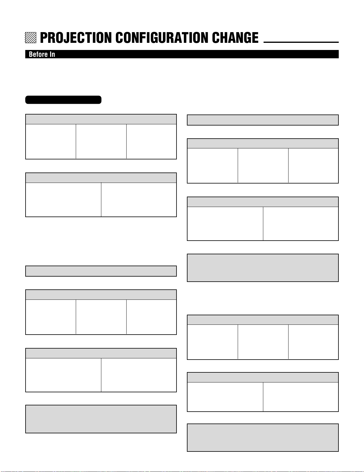
PROJECTION CONFIGURATION CHANGE.
Before Installation Change
The projector is electrically and mechanically set for 100 inch diagonal screen, front throw ceiling mount and a projection angle of
12.4˚ (XG85)/12.2˚(XG135LC). If your application is different from the factory setting(for example, ceiling to floor and screen
size between 60 and 300 inch), you will have to reconfigure the projector for your application. Follow the change procedures
according to the instructions below.
For XG85
To change screen size only:
1) Set the focus ring to the proper position. (See pages15 and 16.)
For 100" screen size
R – A-3, B-3
G – A-1, B-3
B – A-3, B-3
For 120" screen size
R – A-3, B-3
G – A-1, B-3
B – A-3, B-3
For 180" screen size
R – A-5, B-5
G – A-1, B-5
B – A-5, B-5
f
2) Adjust the angle of the CRT's. (See page 16.)
To change to the ceiling mount system (rear)
1) Reverse the scan. (See page 14.)
f
2) Set the focus ring to the proper position. (See pages 16 and 17.)
For 100" screen size
R – A-3, B-3
G – A-1, B-3
B – A-3, B-3
For 120" screen size
R – A-3, B-3
G – A-1, B-3
B – A-3, B-3
For 180" screen size
R – A-5, B-5
G – A-1, B-5
B – A-5, B-5
For 100" screen size
Move the CRT to the 100 position
For 120–180" screen size and the
other screen sizes
Move the CRT to the 120, 180, or
60–300 position
To change to the desk top system (front)
1) Reverse the scan. (See page 14.)
f
2) Set the focus ring to the proper position. (See pages 15 and 16.)
For 100" screen size
R – A-3, B-3
G – A-1, B-3
B – A-3, B-3
For 120" screen size
R – A-3, B-3
G – A-1, B-3
B – A-3, B-3
For 180" screen size
R – A-5, B-5
G – A-1, B-5
B – A-5, B-5
f
3) Adjust the angle of the CRT's. (See page 16.)
For 100" screen size
Move the CRT to the 100 position
For 120–180" screen size and the
other screen sizes
Move the CRT to the 120, 180, or
60–300 position
f
4) Select an installation from the PJ ORIENTATION menu in
the SETTING menu. (See “Projection Type Selection” in the
setup manual.)
f
3) Adjust the angle of the CRT's. (See page 17.)
For 100" screen size
Move the CRT to the 100 position
For 120–180" screen size and the
other screen sizes
Move the CRT to the 120, 180, or
60–300 position
f
4) Select an installation from the PJ ORIENTATION menu in
the SETTING menu. (See “Projection Type Selection” in the
setup manual.)
To change to the desk top system (rear, 0 projection angle)
1) Set the focus ring to the proper position. (See pages 16 and 17.)
For 100" screen size
R – A-3, B-3
G – A-1, B-3
B – A-3, B-3
For 120" screen size
R – A-3, B-3
G – A-1, B-3
B – A-3, B-3
For 180" screen size
R – A-5, B-5
G – A-1, B-5
B – A-5, B-5
f
2) Adjust the angle of the CRT's (See page 17.)
For 100" screen size
Move the CRT to the 100 position
For 120–180" screen size and the
other screen sizes
Move the CRT to the 120, 180, or
60–300 position
f
3) Select an installation from the PJ ORIENTATION menu in
the SETTING menu. (See “Projection Type Selection” in the
setup manual.)
11
12345
6
6
6
6
6
12345
12345
12345
12345
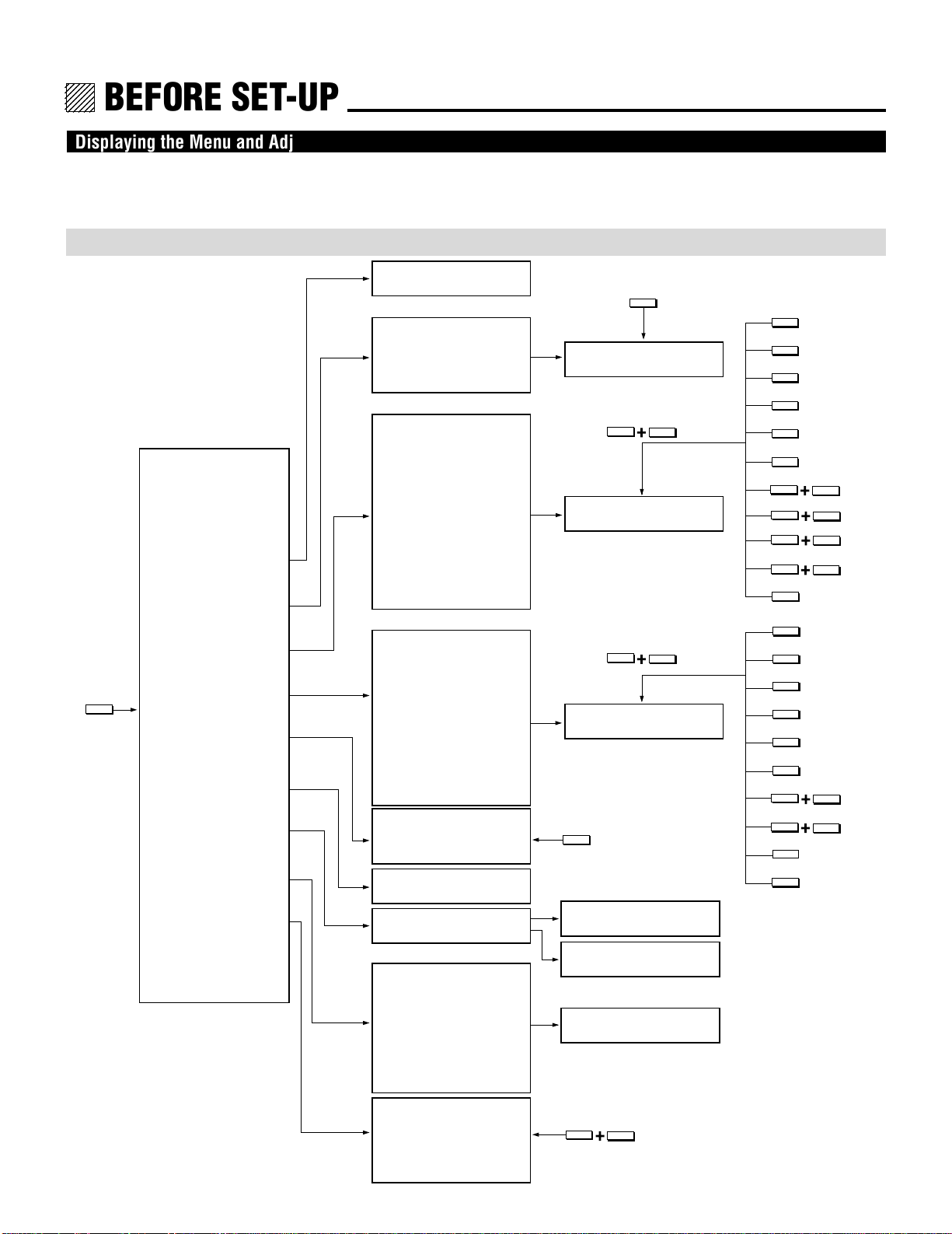
BEFORE SET-UP.
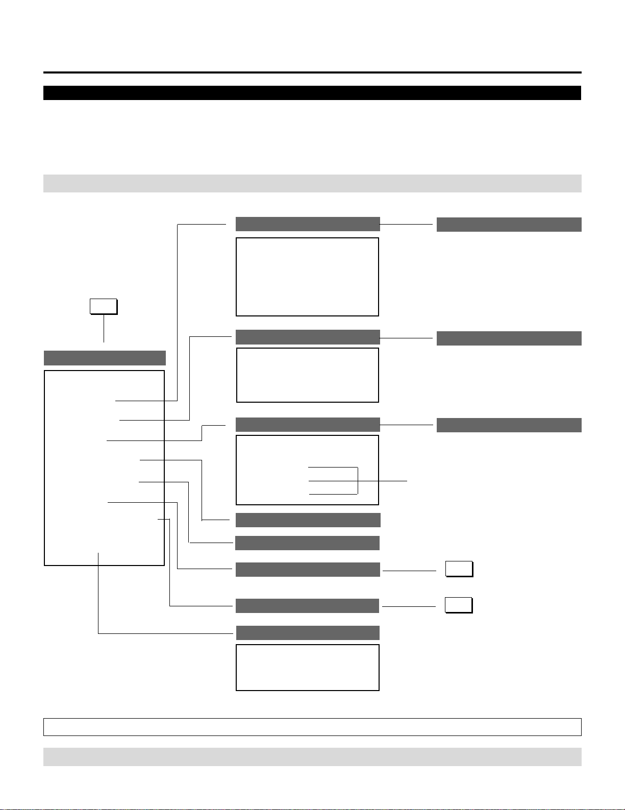
Displaying the Menu and Adjustment Screens
Access of all set-up functions is done through the menu system.
Depending upon button selection, your desired screen will be displayed as shown below:
ADJUST menu
NOTE: Some function items will not be used depending on the input video signal or connected peripheral equipment.
ADJUST
ADJUST menu
– ADJUST –
1 / SIGNAL ENTRY
2 / FOCUS
3 / ALIGNMENT
4 / CONVERGENCE
5 / KELVIN
6 / R,G,B GAIN
7 / PASSCODE
8 / OPTION
SIGNAL ENTRY screen
FOCUS menu
– FOCUS –
1 / CENTER
2 / EDGE ALL
3 / EDGE SEPA.
4 / CORNER
ALIGNMENT menu
– ALIGNMENT –
01 / TILT, SKEW
02 / BOW
03 / AMPLITUDE
04 / LINEARITY
05 / KEY-STONE
06 / PIN-CUSHION
07 / LINEAR-BAL.
08 / KEY-BALANCE
09 / PIN-BALANCE
10 / LINE DIST.
11 / R,G,B POINT
CONVERGENCE menu
– CONVERGENCE –
1 / TILT, SKEW
2 / BOW
3 / AMPLITUDE
4 / LINEARITY
5 / KEY-STONE
6 / PIN-CUSHION
7 / LINEAR-BAL
8 / LINE DIST.
9 / POINT
10/ PHASE
– KELVIN –
1 / COLOR TEMP.
2 / WHITE BAL.
Adjustment screen
FOCUS
Adjustment screen
CTL
Sub menu and
Adjustment screen
CTL
R,B
Sub menu and
Adjustment screen
KELVIN
TILT
BOW
AMPLIT
LINEAR
G
KEYSTN
PINCUS
CTL
CTL
CTL
CTL
POINT
TILT
BOW
AMPLIT
LINEAR
KEYSTN
PINCUS
CTL
CTL
POINT
PHASE
LINEAR
KEYSTN
PINCUS
BOW
LINEAR
BOW
9 / REF. ADJUST
PASSCODE menu
OPTION menu
– OPTION –
NEW PASSCODE?
input screen
PASSCODE
DISABLE? menu
1 / SETTING MODE
2 / MENU MODE
3 / SEQUENCER
4 / PJ ADDRESS
Sub menu
/ Setting screen
5 / VERSION
6 / HOUR METER
7 / DEFAULT DATA
– REF. ADJUST –
1 / ASTIG
CTL
ADJUST
2 / BRIGHT UNIFORM.
3 / WHITE UNIFORM.
4 / RASTER CENTERING
14
12345
6
6
6
6
6
12345
12345
12345
12345
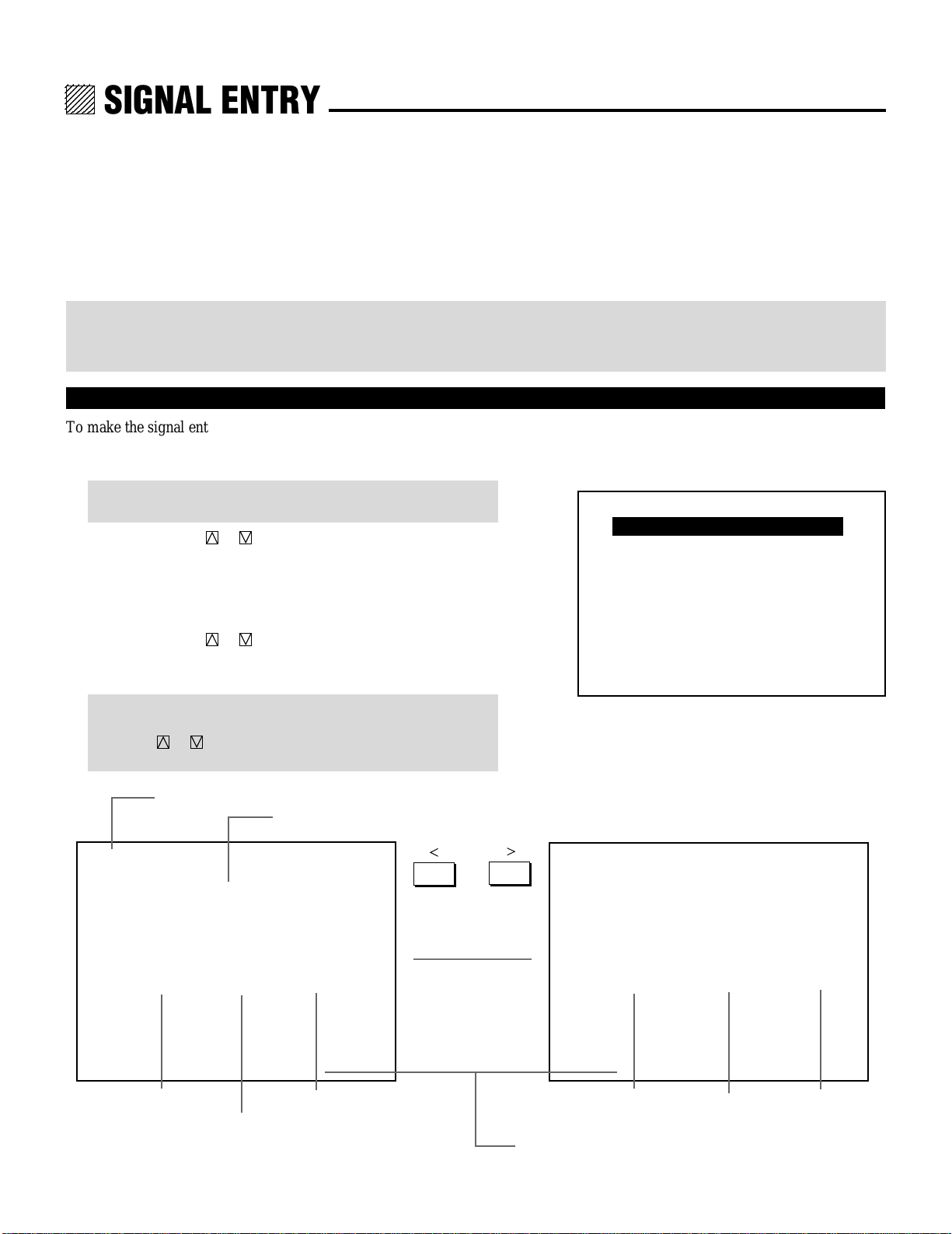
SIGNAL ENTRY.
On Signal Entry
The projector uses a micro-processor to automatically read and distinguish between all video signals input at the same time. These
signals are then used to make optimum adjustments for focus, convergence, alignment, etc. Various parameters must be registered
into the micro-processor beforehand to ensure the video signals are recognized and adjusted to optimum quality.
The Signal Entry registers these video signals in the SIGNAL ENTRY list and at the same time obtains the various parameters
pertaining to these signals. Always access this mode first whenever inputting video signals for the first time so that you can register
the video signals before making any adjustments. If the current input signal(s) has not been registered, the “UNREGISTERED
SIGNAL” message is displayed on screen.
NOTE: If you have software which changes scanning mode due to the graphic board of your PC (such as VGA), it will be necessary
to register signal entry for each scanning mode. This can be done using your PC by way of stopping the software in each scanning
mode and performing a signal entry operation.
Signal Entry Procedures
To make the signal entry, proceed as follows:
1 Press the ADJUST button.
• The “ADJUST” menu is displayed.
NOTE: The projector may ask you to enter your passcode. See
61 for the explanation of the PASSCODE.
2 Use the CURSOR or button to highlight the “1/SIGNAL
ENTRY” line and press ENTER.
• The “SIGNAL ENTRY” list will be displayed.
• You can also select the “SIGNAL ENTRY” list directly by
pressing the INPUT “1” button.
3 Use the CURSOR or button to select the desired line and
press ENTER.
• The Signal entry menu will be displayed.
– ADJUST –
1 / SIGNAL ENTRY
2 / FOCUS
3 / ALIGNMENT
4 / CONVERGENCE
5 / KELVIN
6 / R,G,B GAIN
7 / PASSCODE
8 / OPTION
9 / REF.ADJUST
NOTE: To advance to the next page or to the previous page,
hold down the CTL button then press the
CURSOR or button. To directly access a page, hold down
the CTL button then press any one of the INPUT buttons.
Page / total pages – sheet No.
Connect condition of the Switcher
P01/10–1 SIGNAL ENTRY
STANDALONE
NO
01
02
03
04
05
06
07
08
09
10
NAME
NTSC3.58
NTSC4.43
PAL
SECAM
VESA1024
OUTPUT DATA : LIST NO.✻✻
SOURCE
VIDEO
VIDEO
VIDEO
VIDEO
RGB
INPUT
A
A
A
A
A
§ ©
Signal name
Input terminal
P01/10–2 SIGNAL ENTRY
STANDALONE
NO
01
02
03
04
05
06
07
08
09
10
DATE
00/00/00
00/00/00
00/00/00
00/00/00
00/00/00
OUTPUT DATA : LIST NO.✻✻
Entry dateRgistered input module
FH
15.74kHz
15.74kHz
15.74kHz
15.74kHz
48.60kHz
Horizontal
FV
60.00Hz
60.00Hz
50.00Hz
50.00Hz
60.00Hz
Frequency
Output data for the signal currently projected.
Vertical
Frequency
19
12345
6
6
6
6
6
12345
12345
12345
12345
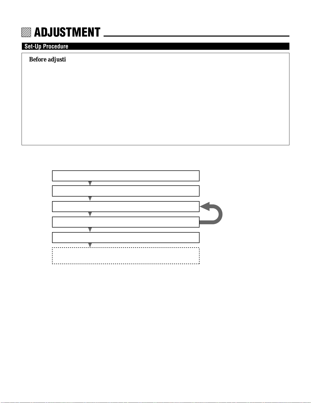
ADJUSTMENT.
Set-Up Procedure
Before adjusting
1 Installation of the projector.
• This projector is pre-adjusted at the factory for 100 inch screen front projection at 12.4˚ for XG85 and 12.2˚ for
XG135LC, and ceiling mounting. If your application is the same as the factory setting, you will not have to
reconfigure the projector for your application. However, if you want to do some fine or further adjustments, carry out
the following adjustments.
2 Connect the external equipment to the projector.
3 Turn on power to the external equipment and the projector.
• If you want to institute the use of a passcode, register the passcode. See page 62.
• Carry out the adjustments after displaying an image for 20 minutes or more.
4 Select the input signal.
• If your input signal has not been recorded, it is necessary to perform the signal entry beforehand. See page 19.
If you want to use the projector in any other configuration than the factory setting, perform the following after installation.
1) Electrical Focus Adjustment See page 39
2) Alignment Adjustment See page 43
3) Static Convergence Adjustment See page 50
4) Dynamic Convergence Adjustment See page 51
5) Color temperature & White Balance Adjustment See page 59
6) R, G, B Gain Adjustment See page 60
(only when used with the ISS-6020/ISS-6020G)
*If a wrong button is pressed accidently, an error message will appear.
* Pressing the HELP button will display a brief description of the
selected function and button operation instructions.
Check and adjust again
if necessary
38

12345
6
6
6
6
6
12345
12345
12345
12345
PASSCODE.
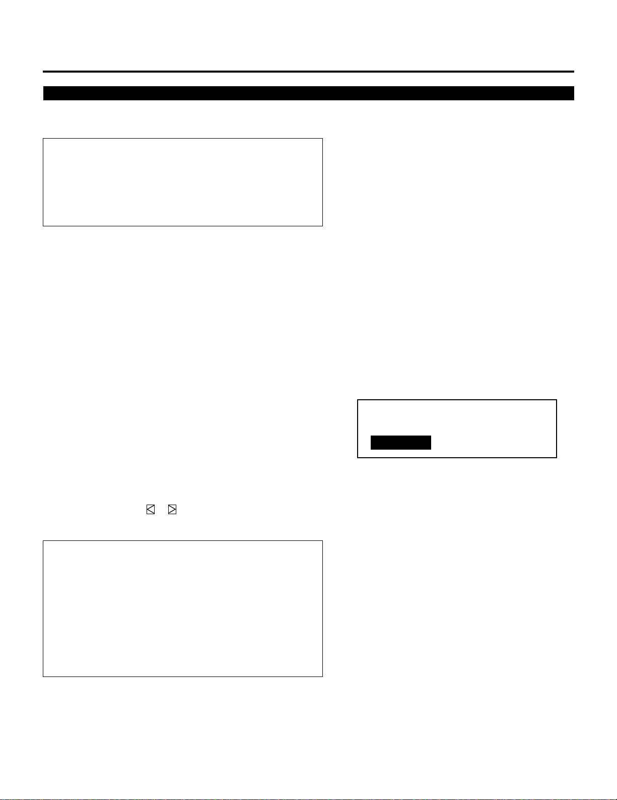
Entering Passcode
To prevent any unauthorized operation or mis-adjustment, the
projector is equipped with a passcode option. If your passcode has
not been entered correctly, the “ADJUST” and “REF. ADJUST”
menus will not be displayed. When the ADJUST button is pressed,
and no passcode has been entered, the “PASSCODE?” screen is
displayed. Enter your passcode.
To do this, proceed as follows:
1 Press the ADJUST button.
• The “PASSCODE?” screen is displayed.
2 Enter the four digit passcode you have already registered by
using the “1” through “0” buttons.
1) Each time you press the INPUT button, an asterisk appears
under the “PASSCODE?” message.
2) After you have finished entering the four digit passcode, press
ENTER.
PASSCODE?
∗∗∗∗
NOTE: If you have made an error, press the NORMAL button to
delete the asterisk “∗”. Then re-enter the correct passcode. To
delete all the entered digits, hold down the CTL button then
press the NORMAL button.
3) If the entered passcode is correct, the “ADJUST” menu is
displayed.
NOTE: If the passcode is not correct, the “WARNING DIFFERENT PASSCODE!!” message is displayed and you are required
to enter the correct passcode.
3 Proceed to each adjustment and setting.
61

12345
6
6
6
6
6
12345
12345
12345
12345
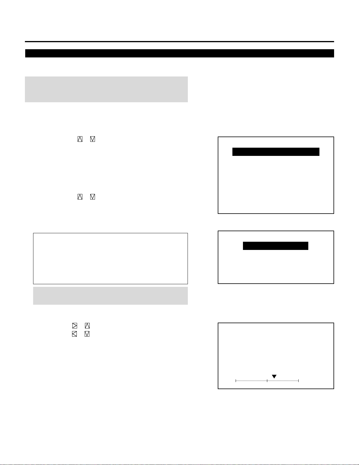
SETTING.
Displaying the Various Setting Features
You can view some of the setting features and check to make sure
that the settings are appropriate.
To display setting features on the screen, hold down CTL and press
INFO.
To eliminate the display, press END.
The parameters cannot be changed on the SETTING VIEW screen
shown on the right.
For changing parameters of the setting features, refer to the following pages.
NOTE: The INPUT TERMINAL item on the “SETTING MODE” menu
cannot be changed.
P01/P03
PJ ORIENTATION
CONNECT CONDITION
DEFAULT INPUT SELECT
OPTION – SETTING MODE –
CEILING
FRONT
STANDALONE
LAST
FOCUS EDGE MODE ALL
S-VIDEO MODE SELECT S2
VIDEO MODE SELECT
AUTO
68
12345
6
6
6
6
12345
12345
12345
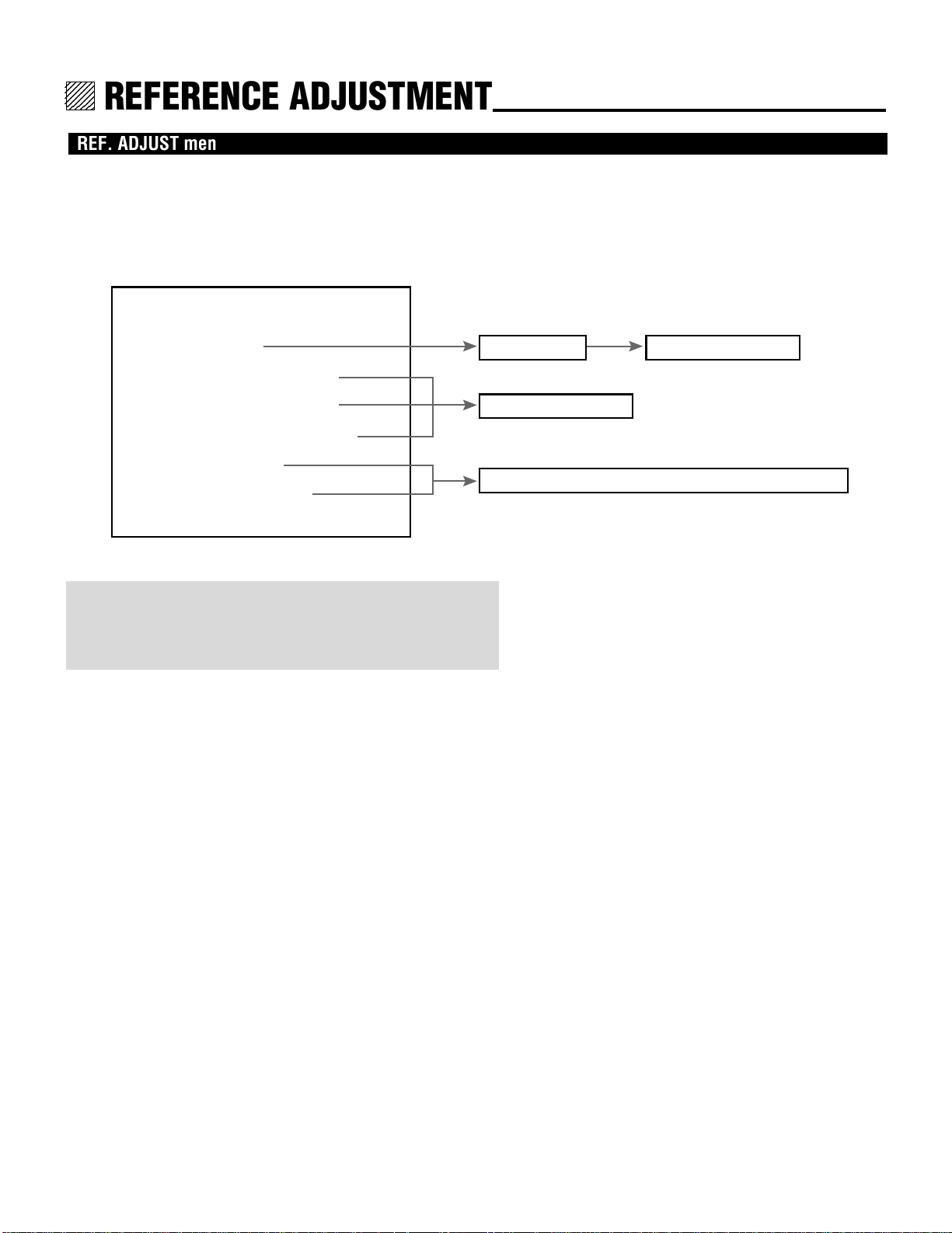
REFERENCE ADJUSTMENT
REF. ADJUST menu
Adjustments contained in this menu are criteria. The adjustments are
performed once after installation. The projector has only one data
area for all the registered signals.
Further adjustments are not necessary in normal use. Leave the
settings as they are at the factory.
– REF. ADJUST –
1 / ASTIG
2 / BRIGHT UNIFORM.
3 / WHITE UNIFORM.
4 / RASTER CENTERING
5 / FOCUS BAL.
6 / REF.WHITE BAL
NOTE
Items 5 and 6 cannot be selected as they are for service personnel
only. If you try to select one, the “For service personnel only”
message is displayed at the bottom of the screen.
• Press and hold the CTL button then press to display the “REF.
ADJUST” menu.
The “REF. ADJUST” menu can also be displayed by selecting the
“9/REF. ADJUST” item in the ADJUST menu.
ASTIG menu
Adjustment screen
Adjustment screen
For service personnel only (cannot be selected)
123
12345
6
6
6
6
6
12345
12345
12345
12345
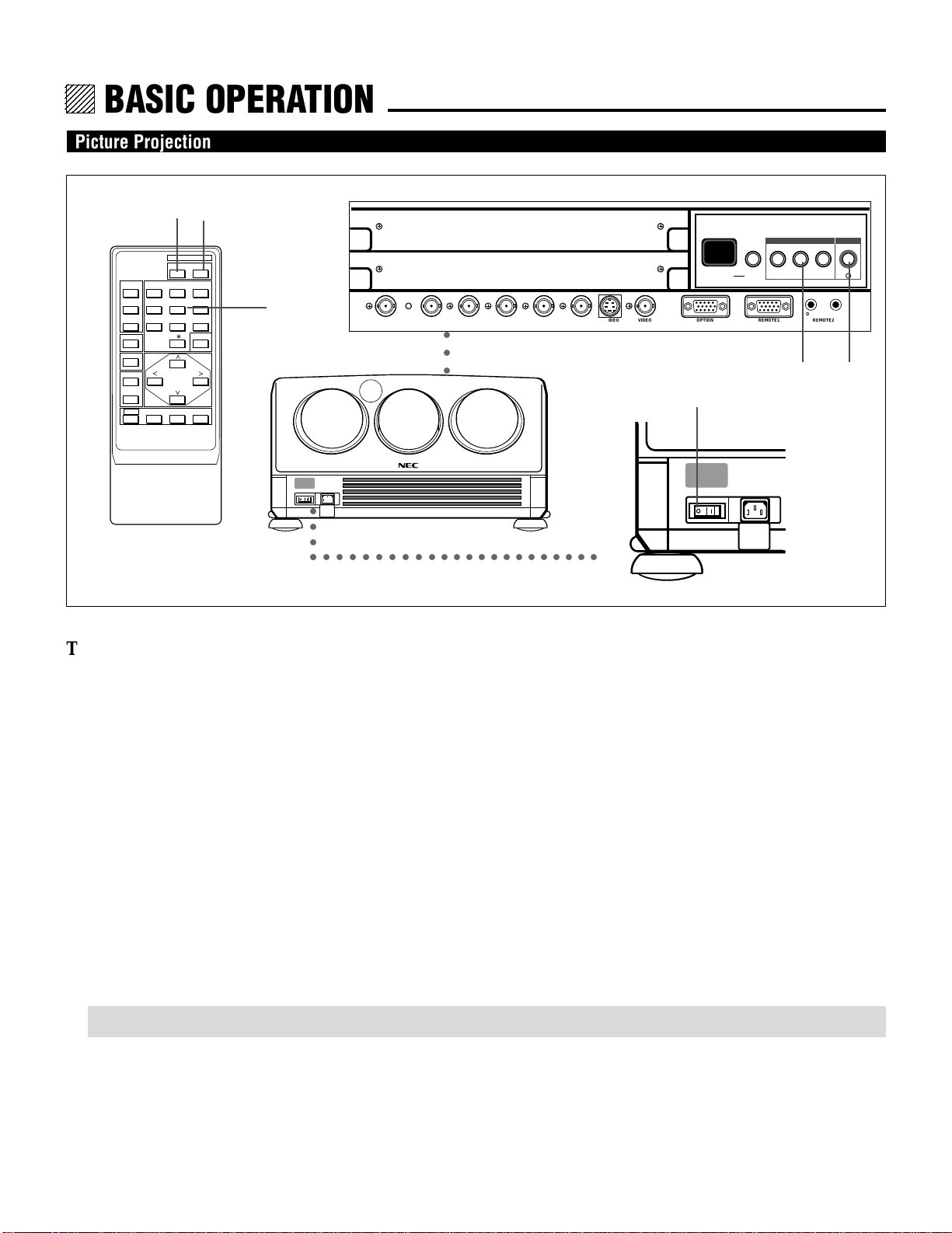
BASIC OPERATION.
Picture Projection
3 6
POWER
ON OFF
OPERATE
1 ABC 2 DEF 3 GHI
PICTURE
4 JKL 5 MNO 6 PQR
MUTE
SOUND
MUTE
DISPLAY
STATIC
R
B
7 STU 8 VWX 9 YZ /
10 ,.
NORMAL ENTER
CAPTION
ENDCTL
4
Projector
○○○○
Rear panel
INPUT SELECT POWER
INPUT SELECT ENTERON/OFFINDICATOR
ACAT OUT R/Cr G/Y B/Cb H/HV V S-VIDEO VIDEO OPTION REMOTE1 REMOTE2
○○○
OUT IN
17
I
364
User remote control
○○○○○○○○○○○○○○○○○○○○○○○
Front panel
To project a picture source, proceed as follows:
1 Turn on the main power of the projector.
• Press the POWER switch on the front panel to the ON position (I).
2 Turn on the power of the connected equipment.
3 Turn on the power of the projector.
• Press the POWER ON button on the remote control or the POWER button on the rear panel.
4 Select an input signal source by pressing one of the ten INPUT buttons on the remote control. You can also select a signal from
the “INPUT SELECT” list.
• See “INPUT SELECTION” on page 24 for more details.
5 Adjust the picture and sound.
• See pages 20 through 23 for more details.
NOTE: The volume function works only with the ISS-6020/ISS-6020G Switcher.
6 To turn off the power, press the POWER OFF button on the remote control or the POWER button on the rear panel.
7 Press the POWER switch on the front panel to the OFF position (V) to turn off the main power of the projector.
8 Last, turn off the connected equipment power.
16

12345
6
6
6
6
6
12345
12345
12345
12345
TIMING CHARTS.
Pre-set Signals
The following signals have been set by factory.
P01/10-1 INPUT SELECT
STANDALONE
NO
01
02
03
04
05
06
07
08
09
10
NAME
NTSC3.58
NTSC4.43
PAL
SECAM
VESA1024
SOURCE
VIDEO
VIDEO
VIDEO
VIDEO
RGB
INPUT
A
A
A
A
A
130

12345
6
6
6
6
6
12345
12345
12345
12345
SPECIFICATIONS.
rojection type ................. Refraction type
Projector and screen are separated
Projection system .......... 3 lens and 3 CRTs in-line
Scanning frequency ....... (XG-1352/XG-1352G)
H 15 to 135 kHz/V 40 to 160Hz
(XG-852/XG-852G)
H 15 to 85 kHz/V 40 to 160Hz
Retrace time .................. H 6.0 µS (fH 15 to 30kHz)
H 2.6 µS (fH 30 to 77kHz)
H 2.0 µS (fH 77 to 120kHz)
H 1.4 µS (fH 120 to 135kHz)
V 270 µS
Video bandwidth ............ 150MHz (-3dB) XG-1352/XG-1352G
110MHz (-3dB) XG-852/XG-852G
CRT ............................... 8 inch liquid cooled
Deflection angle 90 degrees
Lens .............................. Hybrid lens with ECP and ARC , F1.1
HD-134: XG-1352/XG-1352G
HD-144N: XG-852/XG-852G
(ECP: Enhanced Color Purity except B-lens/ARC:
Anti-Reflective Coating)
Picture size .................... 60 to 300 inches diagonal
Resolution ..................... 1500TV lines at center (HDTV)
1350TV line at corner (HDTV)
Pixel resolution .............. 250022000 dots (Addressable)
(XG-852/XG-852G: 160021200 dots )
Light output ................... 240 ANSI lumens (XG-1352/XG-1352G, 230 ANSI
lumens (XG-852/XG-852G)
High voltage .................. 32kV
Input .............................. RGB signal 0.7Vp-p 75 ohm positive (BNC)
H/V sync 0.7 to 4.0Vp-p 75 ohm/High Z negative
or positive (BNC)
COMP sync 0.7 to 4.0Vp-p 75 ohm/High Z
negative or positive (BNC)
Sync on G 0.3 to 0.6Vp-p 75 ohm negative (BNC)
COMP Video 1.0Vp-p 75 ohm positive (BNC)
S-video: Y 1.0Vp-p 75 ohm positive
C 0.28Vp-p 75 ohm (burst level)
COMPONENT; 1.0Vp-p 75ohm negative (BNC)
Cr,Cb 0.7Vp-p 75ohm (BNC)
Video system NTSC, PAL, SECAM and NTSC4.43
Convergence.................. Digital convergence (Pre-set 100 positions)
Quick copy convergence
Static and wave convergence
Point convergence, Zone convergence
Convergence limits ........ Less than 0.2% of V-height
Warm up time ................ 20 minutes
Setup signal................... Cross hairs, Cross hatch, Dot, Window Pattern, H
test pattern
Power supply ................. AC 120V 60Hz (XG-1352/XG-852)
AC 220-240V 50Hz (XG-1352G/XG-852G)
Power consumption ...... 750W (XG-1352), 690W (XG-852)
730W(XG-1352G), 660W (XG-852)
Input current ................. 6.7A (AC 120V)XG-1352
6.2A (AC 120V)XG-852
3.4A (AC 220-240V)XG-1352G
3.1A (AC 220-240V)XG-852G
Safety and regulation XG-1352/XG-852;
Meets FCC class A requirements
UL Approved (UL 1950, CSA 950)
DHHS Approved
Meets DOC (Canada)
Meets RED ACT
XG-1352G/XG-852G;
Meets EMC Directive (EN55022,EN61000-3-2,
EN61000-3-3, EN50082-1)
Meets Low Voltage Directive (EN60950, TÜV
GS Approved)
PTB Approved
Cabinet dimensions ....... 610(W)X812(D)X325(H) mm
24.02(W)X31.97(D)X12.80(H) inch
Weight ........................... 63.0 kg/139.0 lbs(XG-852/XG-852G)
67.4 kg/148.7 lbs (XG-1352/XG-1352G)
Remote control .............. Wired application
Wireless (operating distance 7m/23ft.)
Remote control functions
..... User remote (RC-6320); Power ON/OFF, Input
signal select, Picture mute, Bright, Contrast, Color
1)
, Sharpness 1), Tint 2), Volume 3), Sound mute 3),
Source information, Static convergence, Normalize, Enter, End, Closed Caption
Full function remote (RC-6321); Test, Display, Help,
Information, Input list, Static focus, Edge focus, H/
V position, White balance select, Static convergence, Wave convergence, Point convergence, H/V
amplitude, H/V linearity, H/V key-stone, H/V pincushion, H/V blanking, Tilt, Skew, H/V bow, Store,
Normalize, Enter, End
Main control function .... Power ON/OFF, Input signal select,
External control ............. Power ON/OFF, Input signal select, Picture mute,
Sound mute
3)
, Remote control data input
PC control ..................... Acceptable
Supplied accessories ..... Full function remote control unit (RC-6321), User
remote control unit (RC-6320), Remote cable
16m/52ft., AC line cable, Terminal cover,
Operation manual, Set-Up manual*, Installation
manual*
Environment .................. Temperature 0 to 40 degrees C
Humidity 0 to 90% non-condensing
Storage -10 to 50 degrees C
Sound emission............. XG-1352/XG-852 less than 45dB
XG-1352G/XG-852G less than 70dB (A). Complies
with ISO 3744 or ISO 7779
1) This works only for VIDEO signals.
2) This works only for NTSC video signals.
3) This works only with the Switcher operation.
Specifications are subject to change without notice.
The dimensions given for the projector do not include
protruding parts.
*Set-Up manual and Installation manual are not included
with XG-852G/XG-1352G.
37
SUPPLEMENT SHEET
This document reflects changes to the XG85/XG135LC Set-up Manual and Operation Manual and contains the latest
information about our POINT ACAT and Picture Mute.
Set-Up Manual:
Page 54
Adjusting POINT ACAT
This feature automatically corrects convergence for overall screen adjusting 13
convergence points on R and B CRT respectively.
Before adjusting
• To improve accuracy on convergence correction, you must first adjust the
convergence phase and the cursor phase for the best image.
• You can also correct the static convergence using ACAT feature. For more
accurate ACAT convergence correction, first perform the static convergence
using STATIC feature on OPERATE menu or pressing the STATIC button
on the remote control.
• You must adjust the convergence to all the 13 points because ACAT feature
calculates all the adjustment values on the entire screen based on the adjustments values of 13 points on the screen.
• If convergence points on the edges go out of screen, reduce the horizontal
and the vertical amplitude settings using the amplitude feature of the
ALIGNMENT menu so that all the 13 convergence points can be seen on the
screen. After adjusting ACAT, return the horizontal and the vertical amplitude settings to their original and store them.
• The POINT ACAT convergence adjustment is done roughly. So performing
the POINT ACAT can change the convergence adjustment settings even if
you finely adjust the convergence adjustment.
Proceed as follows:
1 Press the ADJUST button to display the “ADJUST” menu.
• If the projector asks you to enter your passcode, enter your passcode.
– ADJUST –
1 / SIGNAL ENTRY
2 / FOCUS
3 / ALIGNMENT
4 / CONVERGENCE
5 / KELVIN
6 / R,G,B GAIN
7 / PASSCODE
8 / OPTION
9 / REF.ADJUST
2 Use the CURSOR or button to highlight the “4/CONVERGENCE”
line. Press ENTER to display the “CONVERGENCE” menu. You can also
select the “CONVERGENCE” menu directly by pressing the INPUT “4”
button.
• The Convergence menu will be displayed.
3 Use the CURSOR or button to select the “09/POINT” item and
then press ENTER. You can also select “POINT” item directly by pressing
an INPUT “9” button.
• The Point menu will be displayed.
- CONVERGENCE01 / TILT,SKEW
02 / BOW
03 / AMPLITUDE
04 / LINEARITY
05 / KEY-STONE
06 / PIN-CUSHION
07 / LINEAR-BAL
08 / LINE DIST.
09 / POINT
10 / PHASE
4 Use the CURSOR or button to select the “4/ACAT” item and
then press ENTER. You can also select “ACAT” item directly by pressing an
INPUT “4” button.
• The ACAT adjustment screen will be displayed.
• You can also select the ACAT adjustment screen directly by pressing and
holding CTL and pressing POINT button on the full function remote control.
5 Hold down the CTL button then press the R or B button to select the CRT
you wish to adjust.
-POINT1/COARSE
2/MEDIUM
3/FINE
4/ACAT
POINT
-ACATCRT-R-
6 Use the CURSOR buttons to move the point cursor to the point where you
want to adjust, then hold down the CTL button and press any one of the
CURSOR buttons to align a point of intersection of the Red or the Blue
pattern with a point of intersection of the Green pattern (reference color).
• Hold down the CTL button and press the CURSOR or to move
the point cursor on the selected CRT color horizontally.
• Hold down the CTL button and press the CURSOR or to move
the point cursor on the selected CRT color vertically.
7 After adjusting all the points, press the ENTER button.
• The projector automatically corrects the convergence of the whole screen.
NOTE:
• The POINT ACAT adjustment may be required two or three times to
improve accuracy depending on the installation condition.
• There may be some cases where you cannot get completely corrected
convergence on the edges of the screen. If this happens, perform convergence adjustments other than POINT ACAT.
• If you decreased the horizontal or/and vertical amplitude and then
performed the POINT ACAT adjustment, return the adjustment to its
previous state.
8 To end this adjustment, press the END button.
• Whenever the END button is pressed, the menus will sequence in this or
der:
“POINT” menu → “CONVERGENCE”menu →“ADJUST” menu →
Sourcescreen
• If the “RETURN USER MODE?” menu appears, use the
CURSOR or button to select either “YES” or “NO” and then press
ENTER. This will exit the ADJUST mode.
G
R or B
RETURN USER MODE?
YES NO
Items to select
• YES ......... When you try to enter the ADJUST mode again, you will need to
re-enter your passcode.
• NO ........... When you try to enter the ADJUST mode again, you will not
need to re-enter your passcode.
Page 8 of Operation Manual and page 9 of Set-Up Manual:
3 PICTURE MUTE Button
You can also mute the picture by holding down CTL and pressing PICTURE
MUTE buttons. To restore the picture, holding down CTL and press PICTURE MUTE again. Or simply press END.
NOTE: When the picture is muted by using CTL and PICTURE MUTE
buttons, even if an input is switched to another or the power is turned off
using the remote POWER OFF button, the mute cannot be canceled. Turning
off the main power will cancel the mute.
5 DISPLAY Button
On-screen display mute function can be canceled by turning off the main
power.
p.32 on Operation Manual:
You can also mute the picture by holding down CTL and pressing PICTURE
MUTE.
See also “Remote Control Unit” of “Part Names and Functions” for more
details.
Printed in Japan
78038101
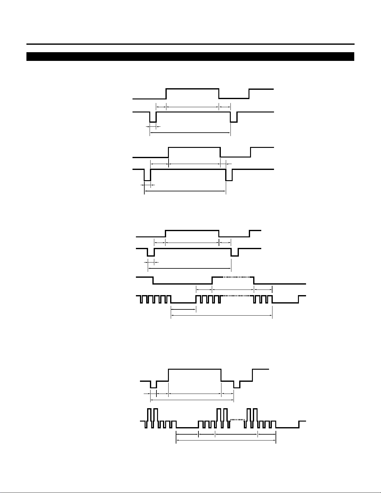
Input Signal Refernce Chart
Separate Sync.
HORIZONTAL
TIMING CHART
VIDEO
C
D
E
VERTICAL
Composite Sync.
HORIZONTAL
VERTICAL
B
C
B
C
B
A
VIDEO
D
A
VIDEO
D
A
E
Sync. Polarity: Positive/Negative
E
VIDEO
C
DE
Composite Sync. & Video (Sync. on Green)
HORIZONTAL
B
VERTICAL
B
VIDEO
C
B
131
A
Sync. Polarity: Positive/Negative
DE
A
VIDEO
CD
A
Sync. Polarity: Negative
E

TIMING CHART
Input Signal Timing
IBM VGA 350
IBM VGA 400
IDTV
Macintosh II
IBM VGA 480
Macintosh Quadra
H µs
V ms
H µs
V ms
H µs
V ms
H µs
V ms
H µs
V ms
H µs
V ms
A
31.8
14.3
31.8
14.3
31.78
16.67
28.57
15
31.8
16.7
14.64
13.342
B
3.8
0.06
3.8
0.06
2.76
0.64
2.12
0.09
3.8
0.06
1.30
0.044
C
1.6
1.72
1.6
0.89
1.6
0.77
3.17
1.11
1.6
0.79
1.32
0.574
D
26.1
11.53
26.1
13.19
26.29
15.14
21.16
13.71
26.1
15.79
11.56
12.68
E
0.3
0.99
0.3
0.16
1.13
0.12
2.12
0.09
0.3
0.06
0.46
0.044
Polarity
`
1
1
`
1
1
1
1
VESA 8002600
(72 Hz)
VESA 10242768
(60 Hz)
• IBM CGA, EGA and VGA are registered trademarks of International Business Machines Corporation.
• Apple is a registered trademark of Apple Computer Inc. Macintosh II and Macintosh Quadra are trademarks of Apple Computer
Inc.
• VESA is an abbreviation for Video Electronics Standards Association.
H µs
V ms
H µs
V ms
20.8
13.887
20.677
16.667
2.4
0.124
2.092
0.124
1.28
0.479
2.462
0.600
16.00
12.510
15.754
15.880
1.12
0.722
0.369
0.062
132
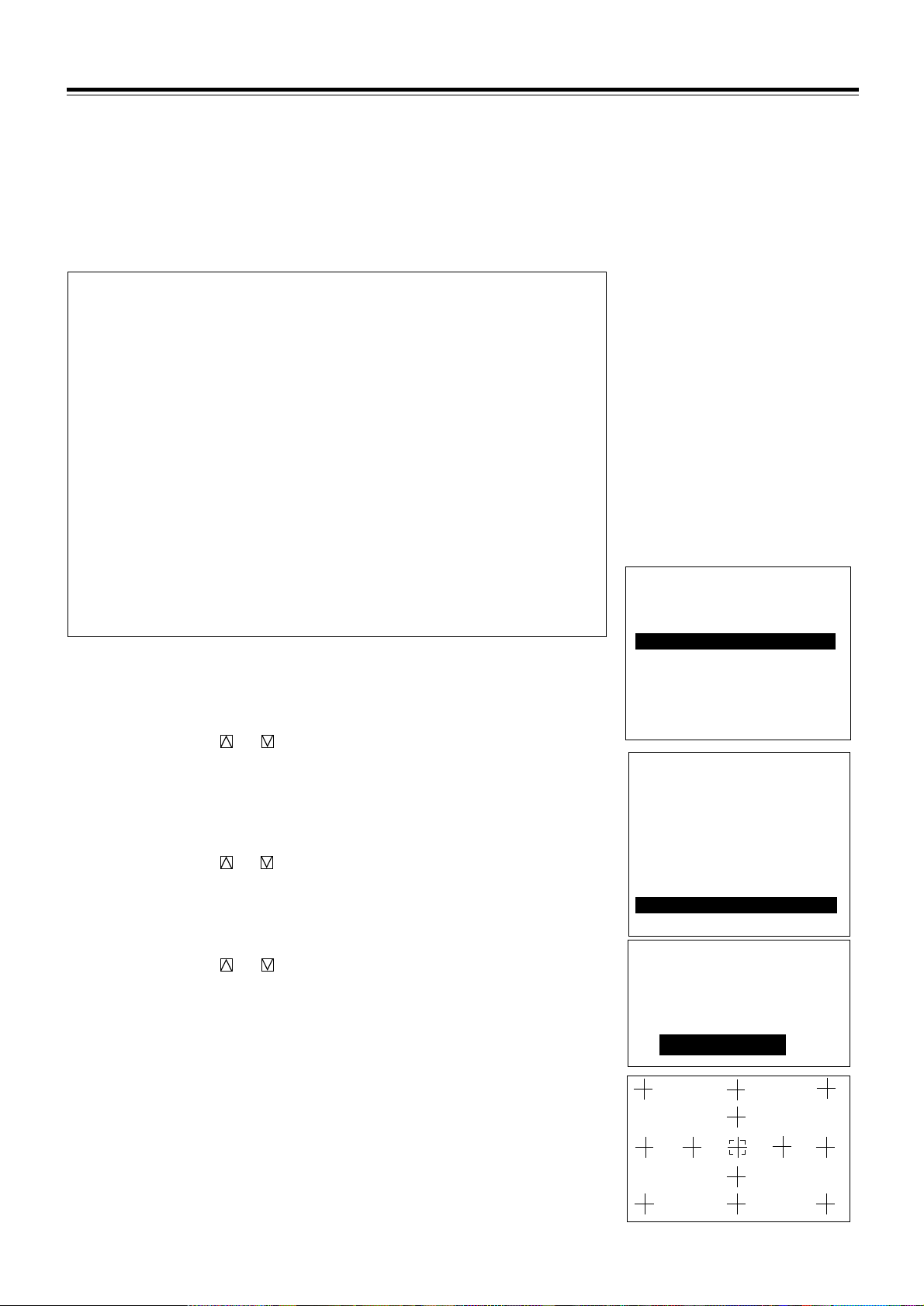
Displaying the Menu and Adjustment Screens
You can easily access your desired screen by selecting menus.
Depending upon button selection, your desired screen will be displayed as shown below:
OPERATE menu
NOTE: Some function items will not be used depending on the input signal or peripheral equipment connected.
BASIC OPERATION
OPERATE
Ä
OPERATE menu
– OPERATE –
1 / PICTURE
2 / POSITION
3 / SOUND
4 / INPUT SELECT
5 / SOURCE INFO
6 / STATIC
7 / CLOSED CAPTION
©
©
©
©
PICTURE menu
– PICTURE –
1 / BRIGHT
2 / CONTRAST
3 / COLOR
4 / SHARPNESS
5 / TINT
POSITION menu
– POSITION –
1 / SHIFT
2 / IMAGE SIZE
3 / BLANKING
SOUND menu
– SOUND –
1 / VOLUME
2 / BASS
3 / TREBLE
4 / BALANCE
INPUT SELECT screen
See page 24
©
©
©
Not available on this series projector
Adjustment screen
See page 20
Adjustment screen
See page 21
Adjustment screen
See page 23
©
8 / T I M E R
CAUTION: Do not display a bright and still picture for longer than 20 minutes. This could damage the CRTs.
NOTE: The explanation of the operation on the following pages is for use with the remote control.
SOURCE INFORMATION screen
©
©
©
Adjustment screen
CLOSED CAPTION screen
Timer setting screen
– TIMER –
1 / ON / OFF TIMER
2 / SLEEP TIMER
17
See page 26
STATIC
§
CAPTION
§
See page 29
See page 27
See page 28
BASIC OPERATION
Storing Projector Settings (Automatic Save Feature)
You have two options to store projector settings in the memory:
automatically and manually.
• Storing time is four seconds.
• The Automatic Save Feature mode has been set to DISABLE by
factory. For information on setting, see “Automatic Save Feature”
in the Set-Up manual included only with the XG-1352/XG-852
models, and if you own XG-1352G/XG-852G, contact your
dealer.
mWhen the Automatic Save Feature mode is set to “ENABLE”,
projector settings will be stored in the projector’s memory
automatically.
Settings are stored automatically when any one of the following
procedures is performed:
• The END button is pressed several times to return the adjustment screen to the source screen.
• One input is switched to another.
• The projector is turned off.
• After every 10 minutes of elapsed time.
mWhen the Automatic Save Feature mode is set to “DISABLE”,
projector settings can be stored in the projector’s memory
manually.
When you try to return the source screen by pressing END
several times, the “STORE ?” menu is displayed.
To manually save settings, proceed as follows:
1. Use the END button to display the “STORE” menu from the
current adjustment screen or menu.
2. Use the CURSOR or button to highlight “CURRENT”,
“NEW”, or “CANCEL” and press ENTER.
Items to select
• CURRENT ------ Overwrites the currently projected signal and
saves the settings. NOTE: An unregistered signal
cannot be stored under the ''CURRENT''
settings.
• NEW ------------ Starting at memory location No.51, this function
saves an unregistered signal as a new signal in
memory.
• CANCEL -------- Does not save settings.
CURRENT
STORE ?
NEW CANCEL
18

mWhen selecting “NEW”
The current settings are registered as a new signal and are
saved to an unassigned line starting at memory location
No.51.
A registered name is automatically given.
The “NEW ENTRY?” menu will be displayed.
Use the CURSOR or button to highlight “YES” or
“NO” and press ENTER.
Items to select
• YES -------------Registers settings as a new signal and
saves the signal in an unassigned
location starting at memory location
No.51.
• NO -------------- Does not register settings.
A registered name is given as follows:
VIDEO/S-VIDEO ----- Video standard with a list number
e.g. NTSC51 or PAL52.
RGB --------------------- ”RGB” with a list number e.g.
RGB60.
BASIC OPERATION
NEW ENTRY?
LIST No. **
NAME ********
YES NO
NOTE:
• If the Input list does not have any unassigned memory
location starting at No. 51 then, the “NEW” item will be
selectable. For signal registration see “SIGNAL ENTRY” in
the Set-Up manual included only with the XG-1352/XG852 models, and if you own XG-1352G/XG-852G, contact
your dealer.
• The Automatic Save Feature is available only for signals
listed in the INPUT LIST.
19
BASIC OPERATION
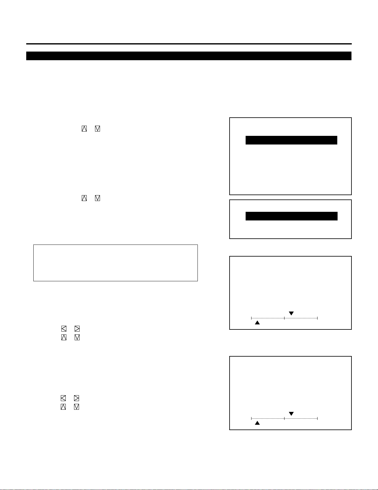
Picture Adjustment
To adjust the picture for each input, proceed as follows:
NOTE: The color, sharpness, and tint controls are not selected in
the “PICTURE” menu for RGB signal. The tint control is not
selected in the “PICTURE” menu for SECAM/PAL signal.
1 Press the OPERATE button.
• The “OPERATE” menu is displayed.
2 Use the CURSOR or button to highlight the “1/PICTURE”
line and press ENTER to display the “PICTURE” menu. You can
also select the “PICTURE” menu directly by pressing the INPUT
“1” button.
3 Use the CURSOR or button to select a picture function and
then press ENTER. You can also select an item directly by
pressing the corresponding number button.
• The picture adjustment screen will be displayed.
Items to select:
• BRIGHT (Brightness control)
• CONTRAST (Contrast control)
• COLOR (Color intensity control)
• SHARPNESS (Picture detail control)
• TINT (Red and green values control)
NOTE: When you are in the BRIGHT adjustment mode, all the
CRTs will be in use. The CRT beam cannot be cut-off.
– OPERATE –
1 / PICTURE
2 / POSITION
3 / SOUND
4 / INPUT SELECT
5 / SOURCE INFO
6 / STATIC
7 / CLOSED CAPTION
8 / T I M E R
– PICTURE –
1 / BRIGHT
2 / CONTRAST
3 / COLOR
4 / SHARPNESS
5 / TINT
4 Use the CURSOR buttons to adjust a picture to your preference.
• The CURSOR or button increases the level.
The CURSOR or button decreases the level.
5 To end this adjustment, press the END button.
• Wherever the END button is pressed, the screen changes in this
order:
“PICTURE” menu → ”OPERATE” menu → Source screen
20
PICTURE
– BRIGHT –
60%
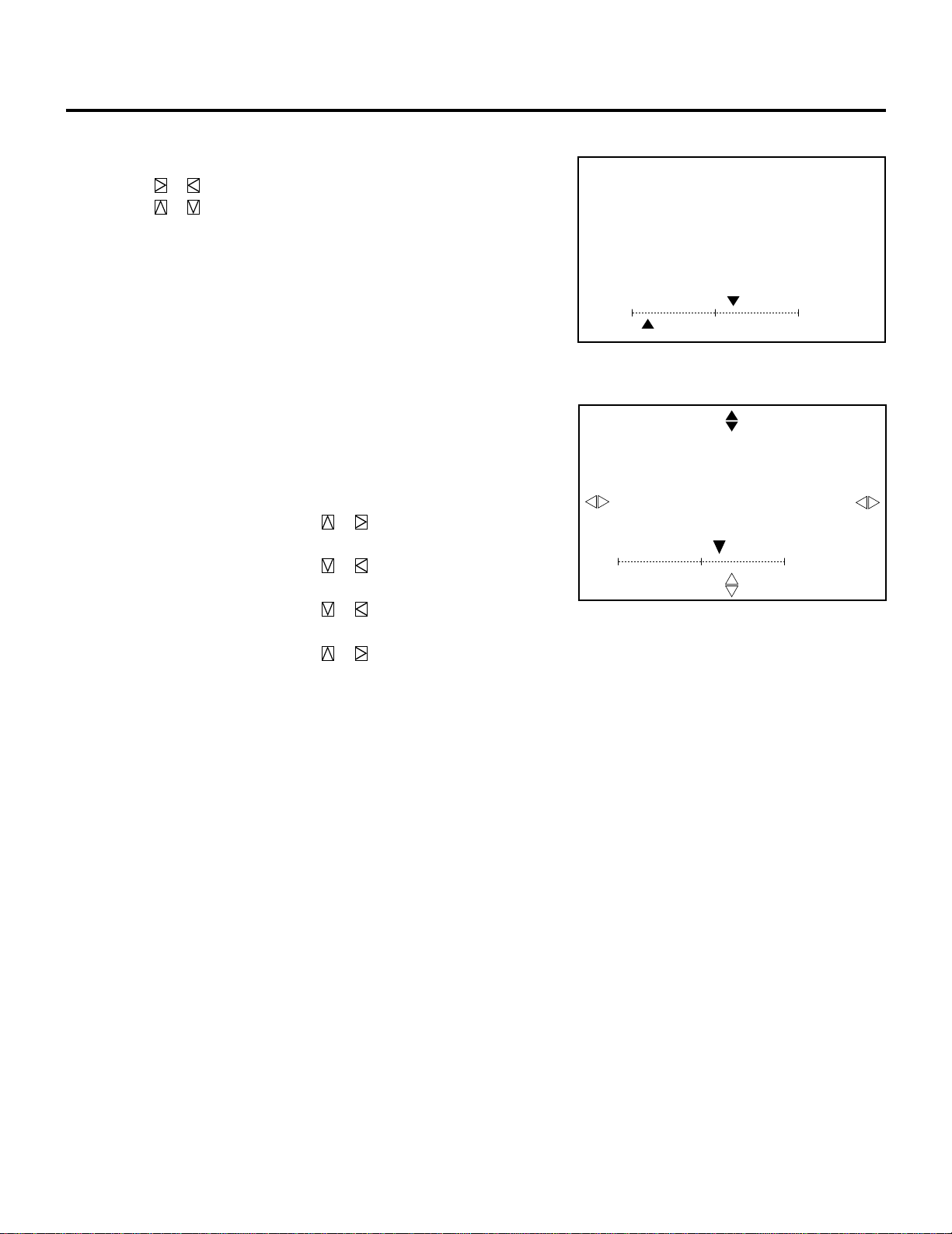
Position Adjustment
Adjust the position(SHIFT), the size (IMAGE SIZE) and the screen
area (BLANKING).
Proceed as follows:
1 Press the OPERATE button.
• The “OPERATE” menu is displayed.
BASIC OPERATION
2 Use the CURSOR or button to highlight the “2/POSITION”
line and press ENTER to display the “POSITION” menu. You
can also select the “POSITION” menu directly by pressing the
INPUT “2” button.
3 Use the CURSOR or button to select either “SHIFT”,
“IMAGE SIZE”, or “BLANKING” and then press ENTER. You
can also select each item directly by pressing the INPUT “1” ,“2”
or “3” button.
• The selected adjustment screen will be displayed.
Items to select
• SHIFT (Position of the picture)
• IMAGE SIZE (Picture size)
• BLANKING(Screen area)
– OPERATE –
1 / PICTURE
2 / POSITION
3 / SOUND
4 / INPUT SELECT
5 / SOURCE INFO
6 / STATIC
7 / CLOSED CAPTION
8 / TIMER
– POSITION –
1 / SHIFT
2 / IMAGE SIZE
3 / BLANKING
POSITION
– SHIFT –
4 Adjust the position, size, or screen area.
When selecting SHIFT:
Use the CURSOR buttons to move the position of the picture.
• Pressing or moves the picture left or right.
• Pressing or moves the picture up or down.
You can also finely adjust the shift .
To do so:
While displaying the SHIFT screen, press and hold CTL and
press any one of the CURSOR buttons to display the SHIFT
FINE screen.
Pressing or moves the picture left or right finely.
Pressing or moves the picture up or down finely.
To return to the SHIFT screen, press and hold CTL, then press
any one of the CURSOR buttons.
21
H
POSITION
– SHIFT FINE –
H
+10%
–90%V
+10%
–90%V
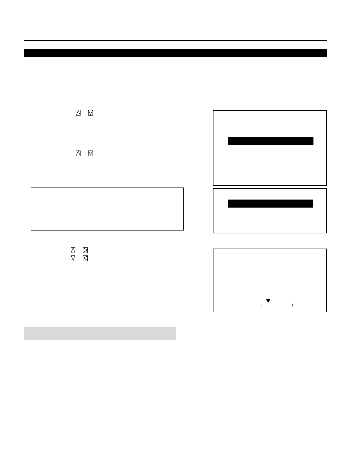
BASIC OPERATION
When selecting IMAGE SIZE:
Use the CURSOR buttons to adjust the size of image.
• Pressing or button increases or decreases the horizontal size.
• Pressing or button increases or decreases the vertical size.
POSITION
– IMAGE SIZE –
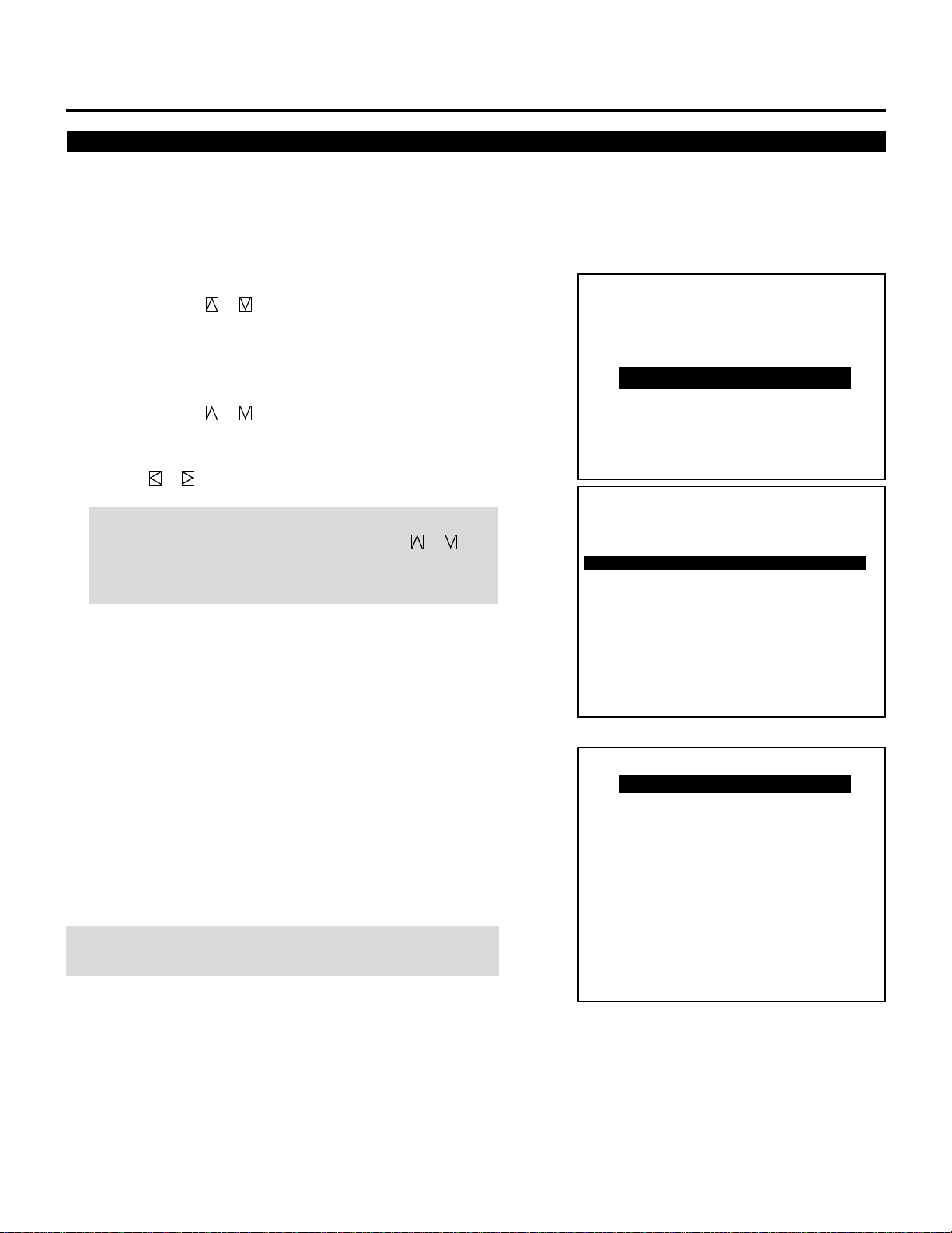
When selecting BLANKING:
1) Hold down the CTL button and press CURSOR buttons to
choose the right, left, top, or bottom edge.
• The marker on the selected side will turn to a solid color.
2) Adjust the blanking using the CURSOR buttons.
Top and Right .................... Pressing or increases the
adjustment values.
Pressing or decreases the
adjustment values.
Bottom and Left ................. Pressing or increases the
adjustment values.
Pressing or decreases the
adjustment values.
5 To end this adjustment, press the END button.
• Whenever the END button is pressed, the screen changes in this
order:
“POSITION” menu → ”OPERATE” menu → Source screen
H
POSITION
– BLANKING –
SCREEN –TOP –
+10%
–90%V
60%
22
Sound Adjustment (only when used with the ISS-6020/ISS-6020G Switcher)
Adjust the volume to your preference.
Proceed as follows:
1 Press the OPERATE button.
• The “OPERATE” menu is displayed.
BASIC OPERATION
2 Use the CURSOR or button to highlight the “3/SOUND”
line and press ENTER to display the “SOUND” menu. You can
also select the “SOUND” menu directly by pressing the INPUT
“3” button.
3 Use the CURSOR or button to select a sound function and
press ENTER. You can also select an item directoly by pressing
the corresponding number button.
• The sound adjustment screen will be displayed.
Items to select
• VOLUME
• BASS (Not available on XG135LC, XG110LC and XG75A)
• TREBLE (Not available on XG135LC, XG110LC and XG75A)
• BALANCE (Not available on XG135LC, XG110LC and XG75A)
4 Use the CURSOR button to adjust sound controls.
• The CURSOR or button increases the level.
The CURSOR or button decreases the level.
5 To end this adjustment, press the END button.
• Whenever the END button is pressed, the screen changes in this
order:
“SOUND” menu → OPERATE” menu → Source screen.
– OPERATE –
1/
PICTURE
2 / POSITION
3 / SOUND
4 / INPUT SELECT
5 / SOURCE INFO
6 / STATIC
7 / CLOSED CAPTION
8 / TIMER
– SOUND –
1 / VOLUME
2 / BASS
3 / TREBLE
4 / BA LANCE
SOUND
– VOLUME –
60%
NOTE: Volume level is indicated in a red gauge during muting.
23
BASIC OPERATION
Input Selection
You can switch from one input to any other input signal.
Proceed as follows:
1 Press the OPERATE button.
• The “OPERATE” menu is displayed.
2 Use the CURSOR or button to highlight the “4/INPUT
SELECT” line and press ENTER to display the “INPUT SELECT” list. You can also select the “INPUT SELECT” list
directly by pressing the INPUT “4” button.
3 Use the CURSOR or button to highlight the signal to be
switched to and press ENTER to switch to the selected input
signal.
Press the or button to change the sheet.
NOTE: To advance to the next page or to the previous page,
hold down the CTL button then press the CURSOR or
button. To directly access the page, hold down the CTL button
then any one of the INPUT buttons.
4 To end the INPUT SELECT list, press the END button.
• Whenever the END button is pressed, the screen changes in this
order:
“OPERATE” menu → Source screen
To select inputs using the INPUT SELECT buttons on the rear
control panel:
1) Press the INPUT button.
• The INPUT SELECT menu is displayed.
2) Press the SELECT button to select an input terminal you wish to
input.
3) Press the ENTER button to execute selection and to switch to the
selected input.
NOTE: Pressing the INPUT button deletes the INPUT SELECT menu
during input selection.
– OPERATE –
1 / PICTURE
2 / POSITION
3 / SOUND
4 / INPUT SELECT
5 / SOURCE INFO
6 / STATIC
7 / CLOSED CAPTION
8 / TIMER
P01/10–1 INPUT SELECT
STANDALONE
NAME
NO
NTSC3.58
01
NTSC4.43
02
PAL
03
SECAM
04
VESA1024
05
06
07
08
09
10
OUTPUT DATA : LIST NO.✻✻
INPUT SELECT
INPUT A RGB
INPUT A VIDEO
INPUT A S-VIDEO
INPUT A COMPONENT
INPUT B RGB
INPUT B VIDEO
INPUT B S-VIDEO
INPUT B COMPONENT
INPUT C RGB
INPUT C VIDEO
INPUT C S-VIDEO
INPUT C COMPONENT
SOURCE
VIDEO
VIDEO
VIDEO
VIDEO
RGB
INPUT
A
A
A
A
A
24
BASIC OPERATION
NOTE:
• While you are viewing a source screen, you can also select the input signal directly by pressing the INPUT “1” through “10”
button. In this case INPUT buttons function as follows:
When using the projector in stand alone operation:
Input Mode
Input Module
A
With RGB board
With VIDEO board
B
C
B
C
RGB
1
4
7
–
–
VIDEO S–VIDEO
2
4
7
4
7
3
5
8
5
8
COMPONENT
1*/10
4
7
–
–
Standard
Optional
(XGRGBIN(A))
Optional
(XGVIDIN(B))
*When INPUT “1” button is selected, RGB and COMPONENT signals are retrieved in this order; when INPUT “10” button is
selected, a COMPONENT signal is retrieved only.
Numbers designate INPUT buttons on the remote control.
When using the projector with the ISS-6020/ISS-6020G:
INPUT 1 through 10 → Selects the corresponding number slot of the ISS-6020/ISS-6020G
When using the projector with two ISS-6020/ISS-6020G or more:
To switch to another input signal, enter the master slot number, then the slave slot number by using INPUT buttons and press
ENTER.
Example:If you want to select a signal from the no.3 slot of the slave Switcher which is connected to the no.2 slot of the master Switcher, first
press the INPUT “2” button, then the INPUT “3” button and then press ENTER.
• You can switch to any input signal of NO 01 through10 on the INPUT SELECT list by holding down the CTL button and pressing
one of the INPUT buttons corresponding to the input number. To activate this function you must first select ENABLE in the
DIRECT ENTRY ACCESS mode. For further details, contact your dealer.
• If there are two or more memory locations that contain the same signal information the projector will reference the signal nearest
the beginning of the list. To select the next signal use the CURSOR or button and press ENTER.
INPUT SELECT List Format
Page / total pages – sheet No.
Connect condition of the Switcher
P01/10–1 INPUT SELECT
STANDALONE
NO
01
02
03
04
05
06
07
08
09
10
NAME
NTSC3.58
NTSC4.43
PAL
SECAM
VESA1024
OUTPUT DATA : LIST NO.✻✻
SOURCE
VIDEO
VIDEO
VIDEO
VIDEO
RGB
Signal name
Input terminal
INPUT
A
A
A
A
A
§ ©
Rgistered input module
25
P01/10–2 INPUT SELECT
STANDALONE
NO
01
02
03
04
05
06
07
08
09
10
DATE
00/00/00
00/00/00
00/00/00
00/00/00
00/00/00
OUTPUT DATA : LIST NO.✻✻
Entry date
FH
15.74kHz
15.74kHz
15.74kHz
15.74kHz
48.60kHz
Horizontal
FV
60.00Hz
60.00Hz
50.00Hz
50.00Hz
60.00Hz
Frequency
Output data for the signal currently projected.
Vertical
Frequency

BASIC OPERATION
Source Information
This is for viewing the signal information and the current status of
various settings.
Proceed as follows:
1 Press the OPERATE button.
• The “OPERATE” menu is displayed.
2 Use the CURSOR or button to highlight the “5/SOURCE
INFO” line and press ENTER to display the “SOURCE INFORMATION” screen. You can also select the “SOURCE INFORMATION” screen directly by pressing the INPUT “5” button.
3 Press the CURSOR or button to select the page.
4 To end the “SOURCE INFORMATION” screen, press the END
button.
• Whenever the END button is pressed, the screen changes in this
order:
“OPERATE” menu → Source screen
– OPERATE –
1 / PICTURE
2 / POSITION
3 / SOUND
4 / INPUT SELECT
5 / SOURCE INFO
6 / STATIC
7 / CLOSED CAPTION
8 / TIMER
NOTE: The items below cannot be set in the OPERATE mode.
P01/03 SOURCE INFORMATION
NAME ✻✻✻✻✻✻✻✻
INPUT TERMINAL INPUT A
INPUT SOURCE RGB
VIDEO MODE RGB
FREQUENCY FH=✻✻✻.✻✻kHz
SYNC POLARITY HD(–) VD(+)
§ ©
P03/03 SOURCE INFORMATION
POSITION WIDE
FONT NORMAL
APERTURE MANUAL
LEVEL1
SYNC TERMINATION 75Ω
AFC NORMAL
§ ©
FV=✻✻.✻✻Hz
§ ©
P02/03 SOURCE INFORMATION
SYNC CONTROL AUTO
COMP.
COUNTER ✻✻✻✻✻
DISPLAY T I M E ✻✻✻✻:✻✻
S O U R C E L O C K OF F
AKB OFF
G-Y MATRIX
26

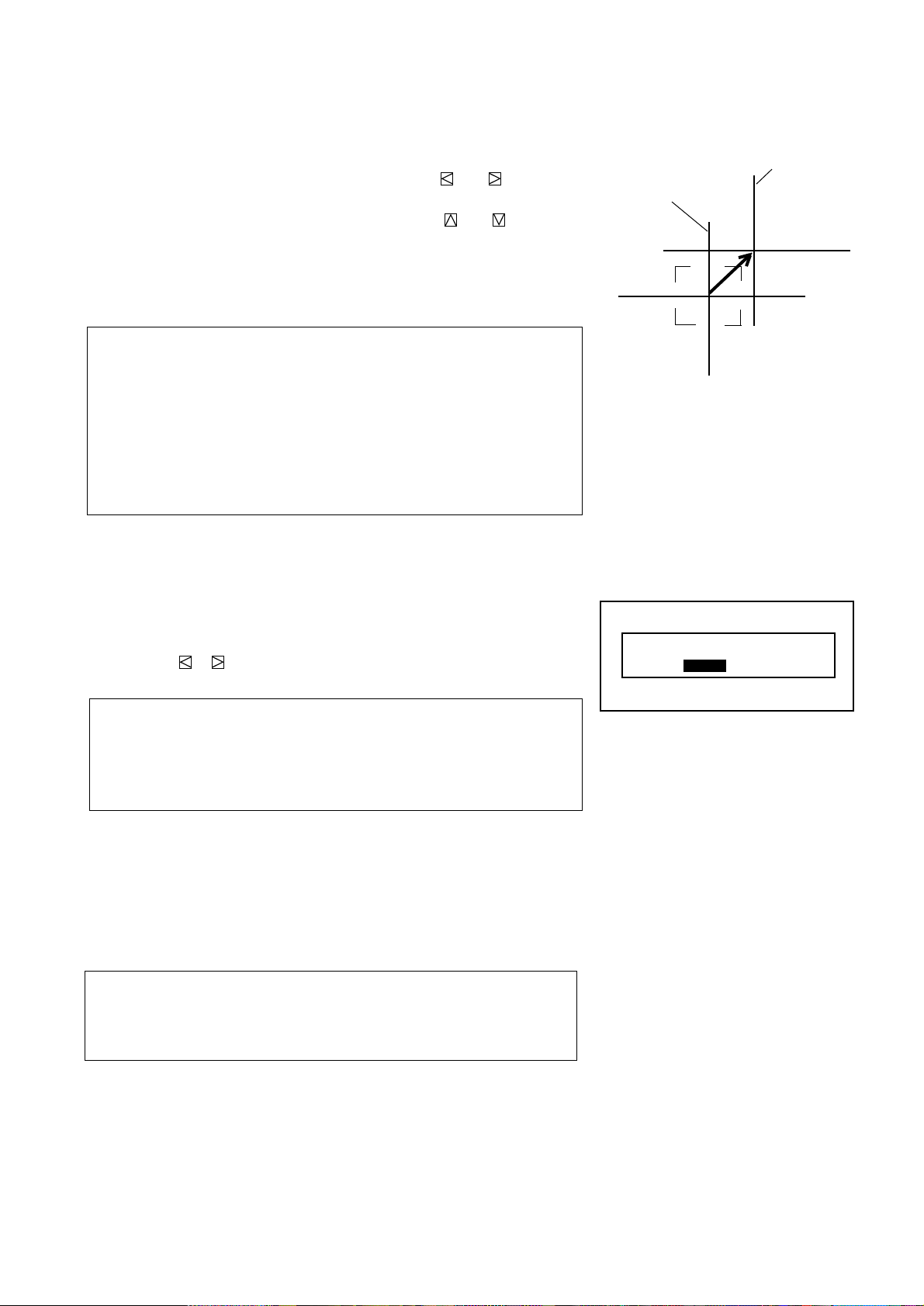
Static Convergence Adjustment
Adjust for the red and blue CRTs to place their pattern on top of the
green test pattern (center only).
NOTE: The static convergence adjustment should be performed for
R and B CRT. Carry out the adjustment after displaying an active
image for 20 minutes or more.
Proceed as follows:
1 Press the OPERATE button.
• The “OPERATE” menu is displayed.
BASIC OPERATION
2 Use the CURSOR or button to highlight the “6/STATIC”
line and then press ENTER to display the STATIC adjustment
screen. You can also select the STATIC adjustment screen
directly by pressing the INPUT “6” button , or by pressing the
STATIC button on the remote control.
• The CROSS-HAIR test pattern will be automatically displayed.
3 Press the R or B button to display the pattern to be aligned with
the Green pattern (as used a reference color).
• You can turn on or off each CRT beam (R and B) separately.
4 Hold down the CTL button then select the CRT you wish to
adjust with the R and B buttons.
5 Align the center of the Red or the Blue pattern with the center of
the Green pattern using the CURSOR buttons.
• The CURSOR or button moves the pattern right or left.
The CURSOR or button moves the pattern up or down.
6 Repeat steps 3 to 5 for the other CRTs if necessary.
– OPERATE –
1 / PICTURE
2 / POSITION
3 / SOUND
4 / INPUT SELECT
5 / SOURCE INFO
6 / STATIC
7 / CLOSED CAPTION
8 / T I M E R
CONVERGENCE
–STATIC–
CRT –R–
H
Red or Blue
+10%
–10%V
7 To end this adjustment, press the END button.
• Whenever the END button is pressed, the screen changes in this
order:
“OPERATE” menu → Source screen
Green
27

BASIC OPERATION
Closed Caption Mode Selection
Several closed caption modes can be set for text to be superimposed
on the projection screen.
To select and set a mode, proceed as follows:
1 Press the OPERATE button.
• The “OPERATE” menu is displayed.
2 Use the CURSOR or button to highlight the “7/CLOSED
CAPTION” item and then press ENTER to display the
“CLOSED CAPTION” menu. You can also select the “CLOSED
CAPTION” menu directly by pressing the INPUT “7” button.
• You can also select the CLOSED CAPTION menu by pressing
the CAPTION button on the remote control.
3 Use the CURSOR or button to select a mode, then press
ENTER.
• The mode selection is executed.
Items to select
• CAPTION 1–4 ...... Text is superimposed
• TEXT 1–4............. Text is displayed in full screen
• OFF ...................... This exits the CLOSED CAPTION mode
NOTE:
1) The closed caption feature will only work with an NTSC3.58
source.
2) Pressing ENTER executes store function. Switching to
source other than NTSC3.58 will cancel this setting. To
activate, select the NTSC3.58 source again.
– OPERATE –
1 / PICTURE
2 / POSITION
3 / SOUND
4 / INPUT SELECT
5 / SOURCE INFO
6 / STATIC
7 / CLOSED CAPTION
8 / TIMER
CLOSED CAPTION
CAPTION1
CAPTION2
CAPTION3
CAPTION4
TEXT1
TEXT2
TEXT3
TEXT4
OFF
4 To return to the operate menu, press the END button.
• Wherever the END button is pressed, the screen changes in this
order:
“OPERATE”menu → source screen
28

Setting Timer
Your projector can be programmed to turn on or off automatically at a specified time. The two timer functions are available: ON/OFF TIMER and SLEEP TIMER.
NOTE:
When the ON TIMER is set and the projector is in standby,
the two digit indicator flashes “00” to indicate that the ON
TIMER is active.
Proceed as follows:
• Before setting ON/OFF TIMER, make sure that the DATE,
TIME PRESET feature is set.
• Even after setting ON/OFF TIMER, turning the projector
on or off with the remote control is possible.
• This timer setting is defeated when the projector carries out
a Sequencer program. See “Auto Sequence Setting” in SetUp manual for more information.
• There are two time display formats: 24-hour or AM/PM
format. You can set either format in the “DATE TIME
DISPLAY” of the OPTION menu See “Various SettingsSetting DATE, TIME DISPLAY Setting” in the Set-Up
manual.
1 Press the OPERATE button.
• The “OPERATE” menu is displayed.
2 Use the CURSOR or button to highlight the “8/
TIMER” item and then press ENTER to display the
“TIMER” menu. You can also select the “TIMER” menu
directly by pressing the INPUT “8” button.
3 Use the CURSOR or button to select “ON/OFF
TIMER” or “SLEEP TIMER”.
BASIC OPERATION
-OPERATE1 / PICTURE
2 / POSITION
3 / SOUND
4 / INPUT SELECT
5 / SOURCE INFO
6 / STATIC
7 / CLOSED CAPTION
8 / TIMER
Items to select
• ON/OFF TIMER .... Programs to turn on or off the
power at a predetermined time.
• SLEEP TIMER...... Programs to turn off the power at a
predetermined time, up to two hours
later in 30-minute increments.
■ Setting ON/OFF TIMER
1) Use the CURSOR or button to select “ON/OFF
TIMER” and press ENTER to display the “ON/OFF
TIMER” menu. You can also select the “ON/OFF
TIMER” menu directly by pressing the INPUT “1”, or
by holding down CTL and pressing POWER ON on the
remote control.
2) Use the CURSOR or button to highlight the
program number and press ENTER to display the
selected “PROGRAM” screen. You can also select the
“PROGRAM” screen by INPUT”1" through “8” button.
- TIMER-
1/ ON / OFF TIMER
2 / SLEEP TIMER
29

BASIC OPERATION
3) Use the CURSOR or button to select “EDIT” or
“CLEAR”, and then press ENTER.
Items to select
• EDIT--------- Enters the mode for changing setting time.
• CLEAR ------ Deletes the current setting time.
When making a new setting or selecting “EDIT”:
Select “EDIT”, and press ENTER to display the “DAY”
setting menu which allows you to set the day of the week
for TIMER.
a) Use the CURSOR or button to select the day of the
week to be registered and press ENTER.
• The “EVERY WEEK” menu is displayed.
Items to select
• MON ------------ Monday
• TUE-------------- Tuesday
• WED------------- Wednesday
• THE-------------- Thursday
• FRI -------------- Friday
• SAT-------------- Saturday
• SUN ------------- Sunday
• MON-FRI ------- Monday thru Friday
• MON-SAT------- Monday thru Saturday
• MON-SUN ------ Monday thru Sunday
b) Use the CURSOR or button to select an item and
then press ENTER.
When “YES” is selected, the item on the day field in the
ON/OFF TIMER menu is marked with the letter “E”
which indicates that the setting time is enabled.
-ON/OFF TIMER-
PRG DAY ON OFF
1
2
3
4
5
6
7
8
ACTIVE INACTIVE
-PROGRAM-
EDIT CLEAR
DAY
MON
TUE
WED
THE
FRI
SAT
SUN
MON-FRI
MON-SAT
MON-SUN
Items to select
• YES -----Programs to turn on or off every week.
(not deleted after executing the program)
• NO ------Does not program to turn on or off every week.
(deleted after executing the program)
• The “ON TIMER” setting screen is displayed.
c) Enter the ON TIMER time in the HH:MM format using
INPUT buttons and the CURSOR or button and
then press ENTER. Pressing NORMAL cancels the ON
TIMER time.
EVERY WEEK?
YES NO
30

• The time display format varies depending on the setting in
“DATE TIME DISPLAY” of the “OPTION” menu.
• The “OFF TIMER” setting screen is displayed.
NOTE:
When the ON TIMER is set alone, the timer is programmed to
turn off after four hours. While this setting is effective, if any
button on the remote control or the rear panel is pressed, or
if any operation is made from the external control, the timer
will extend the current setting time to add four more hours.
d) Enter the OFF TIMER time in the HH:MM format using
INPUT buttons and the CURSOR or button and
then press ENTER. Pressing NORMAL cancels the OFF
TIMER time.
• The time display format varies depending on the setting in
“DATE TIME DISPLAY” of the “OPTION” menu.
• The “ON/OFF TIMER” setting screen is displayed.
When selecting “CLEAR”:
Select “CLEAR” and press ENTER to clear the setting time for
the selected program number.
• The “ON/OFF TIMER” menu is displayed.
4)Use the CURSOR or button to select “ACTIVE” or
“INACTIVE” and then press ENTER.
Items to select
• ACTIVE --------- Enables ON/OFF TIMER
• INACTIVE -------Disables ON/OFF TIMER
When selecting “ACTIVE”:
Select “ACTIVE” and press ENTER to enable the programmed timer function.
• The “ON/OFF” display appears on the top left of the screen.
When the all the programs are completed, this display
disappears.
• When the OFF TIMER is set, the “THE PROJECTOR WILL
TURN OFF SOON” display appears three minutes before
turning off.
BASIC OPERATION
ON TIMER 09 : 00
OFF TIMER 12 : 00
-ON/OFF TIMERPRG DAY ON OFF
1 MON 09:00 12:00
2 MON-FRI 14:00 15:30
3 MON-SAT 18:00 19:00
4 TUE 22:00 06:00
5
6
7
8
ACTIVE INACTIVE
-ON/-OFF TIMERPRG DAY ON OFF
1 MON 09:00 12:00
2 MON-FRI 14:00 15:30
3 MON-SAT 18:00 19:00
E
4 TUE 22:00 06:00
5
6
7
8
ACTIVE INACTIVE
MON 01/16/97 12:00:00
ON/OFF
When selecting “INACTIVE”:
Select “INACTIVE” and press ENTER to disable the
programmed timer function.
• The scree is returned to the “TIMER” menu and the “ON/
OFF” display disappears.
31

BASIC OPERATION
■ Setting SLEEP TIMER
1) Use the CURSOR or button to highlight the “2/
SLEEP TIMER” and press ENTER to display the
“SLEEP TIMER” menu. You can also select the
“SLEEP TIMER” menu directly by pressing the INPUT
“2” or by holding down CTL and pressing POWER
OFF on the remote control.
2) Use the CURSOR or button to select the time
between 30 minutes and 2 hours in 30 minutes.
Items to select
• –:-- ------------Does not use SLEEP TIMER
• 0:30 ----------- 30 minutes
• 1:00 ----------- 1 hour
• 1:30 ----------- 1 and half an hour
• 2:00 ----------- 2 hours
3) Select the desired time and press ENTER.
• The “SLEEP” display appears on the top left of the
screen.
• When the SLEEP TIMER is set, the “THE
PROJECTOR WILL TURN OFF SOON” display appears three minutes before turning off.
-TIMER1/ ON/OFF TIMER
2/ SLEEP TIMER
SLEEP TIMER –:--
SLEEP TIMER 1:30
MON 01/16/95 12:00:00
SLEEP
4) To refer the remaining time, select the “2/SLEEP
TIMER” in the “TIMER” menu and press ENTER to
display the SLEEP TIMER screen. This indicates the
remaining time.
• You can also display the remaining time by holding
down CTL and pressing POWER OFF on the remote
control.
• To change the setting time, repeat the step 2).
5) To cancel the setting sleep time, select the “2/SLEEP
TIMER” in the “TIMER” menu and press ENTER to
display the SLEEP TIMER screen. This indicates the
remaining time. Use the CURSOR or button to
clear the settings. The display changes to “–:--”. Then
press ENTER.
• The “SLEEP” display disappears on the top left of the
screen.
• You can also cancel the time by holding down CTL
and pressing POWER OFF on the remote control.
4 To return to the source screen, press the END button
while the TIMER menu is displayed.
• Wherever the END button is pressed, the screen
changes in this order:
“TIMER” menu → “OPERATE”menu → source screen
SLEEP TIMER –:48
32

BASIC OPERATION
Mute
This function mutes the picture, sound or on-screen display.
To mute picture:
• Press the PICTURE MUTE button. To restore the picture, press the PICTURE MUTE button again or the END button.
You can also mute the picture by holding down CTL and pressing PICTURE MUTE.
To mute sound:
• Press the SOUND MUTE button. To restore the sound, press the SOUND MUTE button again or the END button. Note that this
function works only with the ISS-6020/ISS-6020G.
To mute on-screen display:
• Press the DISPLAY button. To restore the on-screen display, press the DISPLAY button again or the END button. Pressing CTL
+ DISPLAY button together will eliminate the on-screen display: pressing this combination again will restore the display.
NOTE: The OPERATE menu can be accessed in the PICTURE MUTE mode.
See “Remote Control Unit” of “Part Names and Functions” for more details.
Normal, Load, and Cancel Function
Adjustment settings can be returned to the factory preset level, or
previously stored level, or can be cancelled.
To return to the standard level (NORMAL):
1 Press the NORMAL button.
• A confirmation message will be displayed.
2 Use the CURSOR or button to select “YES”.
3 Press ENTER.
• The NORMAL function is performed.
• If you select “NO”, you will exit this mode suspending current
status.
To return to the last stored level (LOAD):
1 Press and hold the CTL button then press the NORMAL button.
• The “LOAD/CANCEL” menu is displayed.
2 Use the CURSOR or button to select “LOAD”.
• A confirmation message is displayed.
3 Use the CURSOR or button to select “YES”.
• If you select “NO”, you will exit this mode suspending current
status.
4 Press ENTER.
• The LOAD function is performed.
XXXXXXXX refers to a specific adjustment item to be
normalized
XXXXXXXX refers to a specific adjustment item to be
loaded or cancelled
XXXXXXXX
DATA NORMALIZE?
YES
XXXXXXXX
LOAD
CANCEL
XXXXXXXX
DATA LOAD?
YES
NO
NO
To cancel the adjustment data (CANCEL):
1 Press and hold the CTL button then press the NORMAL button.
• The “LOAD/CANCEL” menu is displayed.
2 Use the CURSOR or button to select “CANCEL”.
• A confirmation message is displayed.
3 Use the CURSOR or button to select “YES”.
• If you select “NO”, you will exit this mode suspending current
status.
4 Press ENTER.
• The CANCEL function is performed.
33
XXXXXXXX refers to a specific adjustment item to be
loaded
XXXXXXXX
DATA CANCEL?
YES
XXXXXXXX refers to a specific adjustment item to be
cancelled
NO

Data Area for Output and Storage
Adjustment data have different reference data areas depending on each operation.
Adjustment Area
All Gain : All adjustment data except Ref.Adjust data
Ref. Adjust : Ref.Adjust data
Adjustment data fall into two: REF. ADJUST menu adjustment and the other adjustment data (Operate and Adjust menu).
Data area falls into five:
Data Area
INPUT LIST (00-99) : Registered data (100) areas corresponding to INPUT LIST
DEFAULT DATA (1-6) : Default (6) areas divided by horizontal frequency.
Cancel Data : Data to be returned to default
Ref.Adjust Data : REF.ADJUST data (1) area
Ref.Adjust (FACTORY AREA) : REF.ADJUST data (1) area for factory preset.
NOTE: See the Set-up manual for ADJUST and REF.ADJUST menus.
Output Data Area
All Gain
Ref. Adjust Data
Ref. Adjust Data (Factory Area)
Ref. Adjust Data
←
Signal Select
Normalize
Load
Cancel
Ref.Adjust Data
Input List (00-99) or Default Data (1-6)
Default Data (1-6)*
Input List (00-99)*
Cancel Data*
* The above list may be different if NORMAL/LOAD/CANCEL operation is performed during POINT convergence.
Output data during adjusting is the amount of data in each data area and data other than the current adjustment item ( data in
working area).
Example for FINE adjustment
Point Data while adjusting Fine
Normalize
Load
Cancel
Storage Area of Data
* Point adjustment has more than one item and each item has its own working area. However, there is only one area where data is
saved with the Store function, which means no distinction is made among items in data.
Default Data (1-6) + Point data except the current Fine data
Input List (00-99) + Point data except the current Fine data
Cancel Data + Point data except the current Fine data
All Gain
INPUT LIST (00-99)*
Ref. Adjust
REF. ADJUSTSTORE
34

Searching Registered Signals
When a source is switched with the remote control or a signal is input, the projector searches the registered signals and outputs its
adjustment data as follows:
By using the horizontal frequency the projector searches up to 100 signals previously stored in the INPUT LIST and up to six
signals stored in the DEFAULT AREA for a matching or close data to output.
* When a matching data is found in the INPUT LIST, the matching data will be displayed.
* When a data with a different input terminal is found, the input terminal and input signal name will be displayed in yellow and
output its data.
* When the data is found in the DEFAULT AREA, the data will be displayed as NEW SIGNAL.
* When no matching data is found, the nearest thing to a NEW SIGNAL data will be displayed.
This section helps you resolve problems you may encounter while inputting a COMPONENT signal.
* When a copy-guard-capable software source is played on a DVD player, white lines outside of a picture may appear. If this
happens, perform the blanking adjustment.
Regardless of whether or not using a DVD player, when a copy-guarded signal is input, a picture may be distorted at the top of
the screen. If this happens, enlarge the image size to display the portion of distortion outside of the screen.
* When switching signals with the external equipment, there may be cases where G-Sync and DVD signals with horizontal
frequencies of approximately 15 kHz cannot be discriminated. There may be cases where an unregistered G-Sync signal with
a horizontal frequency of approximately 15 kHz may be mistaken for a DVD signal and may not be displayed correctly.
When using G-Sync and DVD signals with horizontal frequencies of approximately 15 kHz at the same time, do not use the
same input terminal.
* A COMPONENT signal can be input with the RGB input board installed when the projector is used with the ISS-6020
switcher on the SW level mode. To enable this, you must first specify the RGB input board as the COMPONENT input
board on the projector. See “Setting Mode-RGB/COMPONENT Searching of the Set-up manual.
35

BASIC OPERATION
Screen Format in Projecting a Picture
NOTE: The example of the screen display is only when used with the ISS-6020/ISS-6020G.
Date
MON 01/16/96 12:00:00
M–01 S–01
XXXX
Current time
Input
Source name
NOTE:
• See the Set-Up manual (not included with XG-1352G/XG-852G) or contact your dealer for changing the on-screen display mode.
• If the main power is not supplied to the projector for three days or more, the built-in clock may be reset. If this happens, contact
your dealer for setting date and time.
36
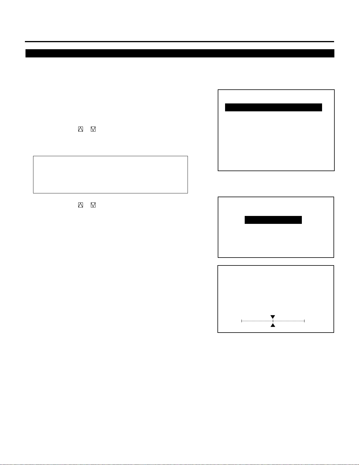
REFERENCE ADJUSTMENT
– ASTIG –
1 / CENTER
2 / EDGE
3 / CORNER
Astig Adjustment
This feature allows you to adjust the beam shape.
Proceed as follows:
1 Press and hold the CTL button then press the ADJUST button to
display the “REF. ADJUST” menu.
• The projector may ask you to enter your passcode.
• See page 61 for the explanation of the PASSCODE.
– REF. ADJUST –
1 / ASTIG
2 / BRIGHT UNIFORM.
2 Use the CURSOR or button to highlight the “1/ASTIG”
item. Press the ENTER or INPUT “1” button to display the
“ASTIG” menu.
Items to select
• CENTER......... Adjusts the whole screen
• EDGE ............. Adjusts the top, bottom, left, and right sides on
the screen
• CORNER........ Adjusts the four corners on the creen
3 Use the CURSOR or button to select the “CENTER”,
“EDGE”, or “CORNER” item. Press the ENTER button to
display the “ASTIG” adjustment screen.
• The “DOT COARSE” test pattern is automatically displayed.
• Pressing The CTL and FOCUS buttons rotates three items as
follows:
CENTER→EDGE→CORNER
4 Select the CRT you wish to adjust with R, G, or B button.
5 Press the R, G, or B button to project the only CRT beam to be
adjusted.
• You can turn on or off each CRT beam (R, G, or B).
3 / WHITE UNIFORM.
4 / RASTER CENTERING
5 / FOCUS BAL.
6 / REF.WHITE BAL
ASTIG
- CENTER -
CRT-G-
0%H
0%V
124

CRT beam to adjusted
• You can turn on or off each CRT beam (R, G, B).
6 Press and hold the CTL then press any one of the CURSOR
buttons to select the position to be adjusted. (The marker on the
selected side will turn to a solid color.)
REFERENCE ADJUSTMENT
ASTIG
• CTL + .......... Top
• CTL + .......... Bottom
• CTL + .......... Right
• CTL + .......... Left
7 Use the CURSOR buttons to adjust the selected position.
• Adjust the center, edge, and corner in this order. If necessary,
repeat the procedure.
• Press CURSOR or button to adjust the selected position
horizontally or vertically.
Press CURSOR or button to adjust the selected position
diagonally.
- EDGE -
CRT - R -
SCREEN - TOP -
HV
SK
ASTIG
- CORNER -
CRT - R -
SCREEN - BR -
HV
SK
60%
40%
60%
40%
8 To end this mode, press the END button.
• Whenever the END button is pressed, the menus will sequence
in this order:
“REF. ADJUST” menu→Source screen
• If the “RETURN USER MODE?” menu appears, use the
CURSOR or button to select either “YES” or “NO” and
then press ENTER. This will exit the REF. ADJUST mode.
Items to select
• YES ...........When you try to enter the ADJUST mode the next
time, you will need to re-enter your passcode.
• NO .............When you try to enter the ADJUST mode the next
time, you will not need to re-enter your passcode.
RETURN USER MODE?
YES NO
125
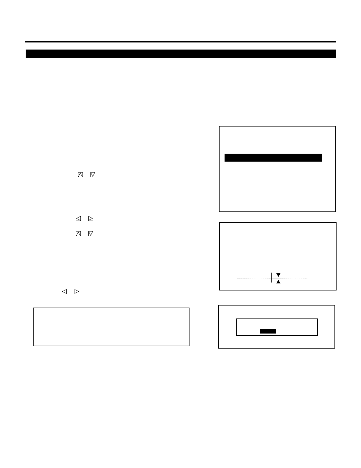
REFERENCE ADJUSTMENT
Bright Uniformity Adjustment
This feature allows you to equalize the brightness between the center
and the edge.
Before adjustment:
• Select the “ALL WHITE” pattern using the TEST button on the full
function remote control.
Proceed as follows:
1 Press and hold the CTL button then press the ADJUST button to
display the “REF. ADJUST” menu.
• The projector may ask you to enter your passcode.
• See page 61 for the explanation of the PASSCODE.
2 Use the CURSOR or button to highlight the “2/BRIGHT
UNIFORM.” item. Press the ENTER or INPUT “2” button to
display the “BRIGHT UNIFORMITY” adjustment screen.
3 Use the CURSOR buttons to adjust the right, left, top, or bottom
edge.
• Press CURSOR or button to increase or decrease the
brightness on the right and the left side.
Press CURSOR or button to increase or decrease the
brightness on the top and the bottom side.
4 To end this mode, press the END button.
• Whenever the END button is pressed, the menus will sequence
in this order:
“REF. ADJUST” menu→Source screen
• If the “RETURN USER MODE?” menu appears, use the
CURSOR or button to select either “YES” or “NO” and
then press ENTER. This will exit the REF. ADJUST mode.
– REF. ADJUST –
1 / ASTIG
2 / BRIGHT UNIFORM.
3 / WHITE UNIFORM.
4 / RASTER CENTERING
5 / FOCUS BAL.
6 / REF.WHITE BAL
BRIGHT UNIFORMITY
BR
H
V
60%
60%
Items to select
• YES.......... When you try to enter the ADJUST mode the next
time, you will need to re-enter your passcode.
• NO ........... When you try to enter the ADJUST mode the next
time, you will not need to re-enter your passcode.
RETURN USER MODE?
YES NO
126

White Uniformity Adjustment
This feature allows you to adjust color balance on the left and the
right side of the screen.
Before adjustment:
• When you are in this mode, all the three CRTs are beamed, and the
CRTs cannot be cut off.
• Select the “ALL WHITE” pattern using the TEST button on the full
function remote control.
Proceed as follows:
1 Press and hold the CTL button then press the ADJUST button to
display the “REF. ADJUST” menu.
• The projector may ask you to enter your passcode.
• See page 61 for the explanation of the PASSCODE.
REFERENCE ADJUSTMENT
2 Use the CURSOR or button to highlight the “3/WHITE
UNIFORM.” item. Press the ENTER or INPUT “3” button to
display the “WHITE UNIFORMITY” adjustment screen.
3 Use the CURSOR buttons to adjust the left and the right edge.
• Press CURSOR or button to increase the amount of blue
on the right side and the amount of red on the left side.
Press CURSOR or button to increase the amount of red on
the right side and the amount of blue on the left side.
4 To end this mode, press the END button.
• Whenever the END button is pressed, the menus will sequence
in this order:
“REF. ADJUST” menu→Source screen
• If the “RETURN USER MODE?” menu appears, use the
CURSOR or button to select either “YES” or “NO” and
then press ENTER. This will exit the REF. ADJUST mode.
Items to select
• YES ......... When you try to enter the ADJUST mode the next
time, you will need to re-enter your passcode.
• NO ........... When you try to enter the ADJUST mode the next
time, you will not need to re-enter your passcode.
– REF. ADJUST –
1 / ASTIG
2 / BRIGHT UNIFORM.
3 / WHITE UNIFORM.
4 / RASTER CENTERING
5 / FOCUS BAL.
6 / REF.WHITE BAL
WHITE UNIFORMITY
B/RR/B
+10%
127
RETURN USER MODE?
YES NO

REFERENCE ADJUSTMENT
Raster Centering Adjustment
This feature allows you to correct he
Note that this adjustment affects all the CRTs at
Proceed as follows:
1 Press and hold the CTL button then press the ADJUST button to
display the “REF. ADJUST” menu.
•The projector may ask you to enter your passcode.
•See page 61 for the explanation of the PASSCODE.
2 User the CURSOR or button to highlight the “4/ RAS-
TER CENTERING” item. Press the ENTER or INPUT “4”
button to display the “RASTER CENTERING” adjustment
screen.
3 Us er the CURSOR buttons to adjust the raster position.
• Pressing CURSOR or moves the raster up.
• Pressing CURSOR or moves the raster down.
4 To end this mode, press the END button.
•Whenever the END button is pressed, the menus will sequence
in this order:
“REF. ADJUST” menu → Source screen
• If the “RETURN USER MODE?” menu appears, use the
CURSOR or button to select either “YES” or “NO” and
then press ENTER. This will exit the REF. ADJUST mode.
– REF. ADJUST –
1 / ASTIG
2 / BRIGHT UNIFORM.
3 / WHITE UNIFORM.
4 / RASTER CENTERING
5 / FOCUS BAL.
6 / REF.WHITE BAL
RASTER
CENTERING
CRT -ALL-
0%V
Items to select
• Y ES ....When you try to enter the ADJUST mode the next time,
you will need to re-enter your passcode.
• NO ......When you try to enter the ADJUST mode the next time,
you will not need to re-enter your passcode.
RETURN USER MODE?
YES NO
128

Appendix
CONTENTS
Timing Charts
Pre-set Signals.............................................130
Input Signal Referecne Chart.......................131
Input Signal Timing ......................................132
Message List...................................... 133
129

Projection Type Selection
This feature allows you to set the installation type according to the
projection configuration.
NOTE:
• After changing the installation condition, be sure to perform this
setting. Setting this automatically reverses the vertical polarity.
However, you will have to reverse the horizontal polarity connectors. If you select a wrong installation type, the projector gives a
warning message. (See the installation manual for the horizontal
scan reversal.)
1 Press the ADJUST button to display the “ADJUST” menu.
• The projector may ask you to enter your passcode.
See page 61 for the explanation of the PASSCODE.
2 Use the CURSOR or button to highlight the “8/OPTION”
line. Press ENTER to display the “OPTION” menu. You can also
select the “OPTION” menu directly by pressing the INPUT “8”
button.
SETTING
– ADJUST –
1 / SIGNAL ENTRY
2 / FOCUS
3 / ALIGNMENT
4 / CONVERGENCE
5 / KELVIN
6 / R,G,B GAIN
7 / PASSCODE
8 / OPTION
9 / REF.ADJUST
3 Use the CURSOR or button to highlight the “1/SETTING
MODE” line. Press ENTER to display the “SETTING MODE”
menu. You can also select the “SETTING MODE” menu directly
by pressing the INPUT “1” button.
4 Use the CURSOR or button to select the “PJ ORIENTA-
TION” item, then press ENTER to display the “PJ ORIENTATION” menu.
NOTE: The SETTING MODE has three menus. The “PJ ORIENTATION” item is on the first menu (P01). To access P02 or P03
from P01, press and hold down the CTL button then press
the button; to return to P01 from P02 or P03, press and hold
down the CTL button then press the button.
– OPTION –
1 / SETTING MODE
2 / MENU MODE
3 / SEQUENCER
4 / PJ ADDRESS
5 / VERSION
6 / HOUR METER
7 / DEFAULT DATA
P01/P03
PJ ORIENTATION
CONNECT CONDITION
DEFAULT INPUT SELECT
FOCUS EDGE MODE ALL
S-VIDEO MODE SELECT S2
VIDEO MODE SELECT
OPTION – SETTING MODE –
CEILING
FRONT
STANDALONE
LAST
AUTO
69

SETTING
5 Use the CURSOR or button to select one of the four
projector installation types and press ENTER.
Items to select
• CEILING/REAR ....Ceiling mounting type and rear projection
• FLOOR/REAR ....... Desk top type and rear projection
• CEILING/FRONT .. Ceiling mounting type and front projection
• FLOOR/FRONT .....Desk top type and front projection
6 To complete, press the END button.
• Whenever the END button is pressed, the menus will sequence
in this order:
“OPTION” menu → “ADJUST” menu → Source screen
• If the “RETURN USER MODE?” menu appears, use the
CURSOR or button to select either “YES” or “NO” and
press ENTER. This will exit the ADJUST mode.
Items to select
• YE S ......... When you try to enter the ADJUST mode the next
time, you will need to re-enter your passcode.
• NO ........... When you try to enter the ADJUST mode the next
time, you will not need to re-enter your passcode.
PJ ORIENTATION
CEILING/REAR
FLOOR/REAR
CEILING/FRONT
FLOOR/FRONT
RETURN USER MODE?
YES NO
70

Connecting to the Switcher
This setting explains how the projector is used with the ISS-6020/
ISS-6020G Switcher.
1 Press the ADJUST button to display the “ADJUST” menu.
• The projector may ask you to enter your passcode.
See page 61 for the explanation of the PASSCODE.
SETTING
2 Use the CURSOR or button to highlight the “8/OPTION”
line. Press ENTER to display the “OPTION” menu. You can also
select the “OPTION” menu directly by pressing the INPUT “8”
button.
3 Use the CURSOR or button to highlight the “1/SETTING
MODE” line. Press ENTER to display the “SETTING MODE”
menu. You can also select the “SETTING MODE” menu directly
by pressing the INPUT “1” button.
4 Use the CURSOR or button to select the “CONNECT
CONDITION” item, then press ENTER to display the “CONNECT CONDITION” menu.
NOTE: The SETTING MODE has three menus. The “CONNECT
CONDITION” item is on the first menu (P01). To access P02 or
P03 from P01, press and hold down the CTL button then press
the button; to return to P01 from P02 or P03, press and hold
down the CTL button then press the button.
– ADJUST –
1 / SIGNAL ENTRY
2 / FOCUS
3 / ALIGNMENT
4 / CONVERGENCE
5 / KELVIN
6 / R,G,B GAIN
7 / PASSCODE
8 / OPTION
9 / REF.ADJUST
– OPTION –
1 / SETTING MODE
2 / MENU MODE
3 / SEQUENCER
4 / PJ ADDRESS
5 / VERSION
6 / HOUR METER
7 / DEFAULT DATA
P01/P03
PJ ORIENTATION
CONNECT CONDITION
DEFAULT INPUT SELECT
FOCUS EDGE MODE ALL
S-VIDEO MODE SELECT S2
VIDEO MODE SELECT AUTO
OPTION – SETTING MODE –
CEILING
FRONT
STANDALONE
LAST
5 Use the CURSOR or button to select your desired connec-
tion condition of Switcher and press ENTER.
• The “RE-START ?” prompt is displayed after setting of the
connection condition is modified from the current status to your
desired condition.
Items to select
• STAND ALONE .... The projector used in stand alone operation.
• SW 1 LEVEL ........ The projector used with one Switcher.
• SW 2 LEVEL ........ The projector used with two or more
Switchers.
71
CONNECT CONDITION
STANDALONE
SW1 LEVEL
SW2 LEVEL

SETTING
6 Use the CURSOR or button to select either “YES” or “NO”
and press ENTER.
Items to select
• YES ......... Restart the projector.
• NO ........... Does not restart the projector.
NOTE: The selected connection condition becomes effective
only after the projector is restarted.
7 To exit, press the END button.
• Whenever the END button is pressed, the menus will sequence
in this order:
“OPTION” menu → “Adjust” menu → Source screen
• If the “RETURN USER MODE?” menu appears, use the
CURSOR or button to select “YES” or “NO” and then
press ENTER.
Items to select
• YE S ......... When you try to enter the ADJUST mode the next
time, you will need to re-enter your passcode.
• NO ........... When you try to enter the ADJUST mode the next
time, you will not need to re-enter your passcode.
RE-START?
YES NO
RETURN USER MODE?
YES NO
72

Default Input Selection
You can set the projector to default to any one of its inputs each time
the projector is turned on.
Proceed as follows:
1 Press the ADJUST button to display the “ADJUST” menu.
• The projector may ask you to enter your passcode.
See page 61 for the explanation of the PASSCODE.
SETTING
2 Use the CURSOR or button to highlight the “8/OPTION”
line. Press ENTER to display the “OPTION” menu. You can also
select the “OPTION” menu directly by pressing the INPUT “8”
button.
3 Use the CURSOR or button to highlight the “1/SETTING
MODE” line. Press ENTER to display the “SETTING MODE”
menu. You can also select the “SETTING MODE” menu directly
by pressing the INPUT “1” button.
4 Use the CURSOR or button to select the “DEFAULT
INPUT SELECT” item, then press ENTER to display the
“DEFAULT INPUT SELECT” menu.
NOTE: The SETTING MODE has three menus. The “DEFAULT
INPUT SELECT” item is on the first menu (P01). To access P02
or P03 from P01, press and hold down the CTL button then
press the button; to return to P01 from P02 or P03, press
and hold down the CTL button then press the button.
– ADJUST –
1 / SIGNAL ENTRY
2 / FOCUS
3 / ALIGNMENT
4 / CONVERGENCE
5 / KELVIN
6 / R,G,B GAIN
7 / PASSCODE
8 / OPTION
9 / REF.ADJUST
– OPTION –
1 / SETTING MODE
2 / MENU MODE
3 / SEQUENCER
4 / PJ ADDRESS
5 / VERSION
6 / HOUR METER
7 / DEFAULT DATA
P01/P03
PJ ORIENTATION
CONNECT CONDITION
DEFAULT INPUT SELECT
FOCUS EDGE MODE ALL
S-VIDEO MODE SELECT S2
VIDEO MODE SELECT AUTO
OPTION – SETTING MODE –
CEILING
FRONT
STANDALONE
LAST
73

SETTING
5 Use the CURSOR or button to select either “LAST” or
“DEFAULT” and press ENTER.
• Selecting “LAST” completes setting. Go on to step 7.
• Selecting “DEFAULT” displays the “Default input” screen. Go
on to step 6.
Items to select
• LAST ....... Sets the projector to default to the previous last
active input each time the projector is turned on.
Note: An input must be active for a minimum of 10
minutes before it is recognized as the last active
signal.
• DEFAULT . Displays the same source input every time the
projector is started up.
DEFAULT INPUT SELECT
LAST
DEFAULT
6 Use the CURSOR or button to select an input and then press
the ENTER button.
When used in stand alone operation:
The default input screen will be displayed.
Use the CURSOR or button to select an input and press
ENTER.
When used with a single Switcher:
The “MASTER” slot menu will be displayed.
Use the CURSOR or button to select the desired slot
number “1” through “10(0)” and then press ENTER.
INPUT SELECT
INPUT A RGB
INPUT A VIDEO
INPUT A S-VIDEO
INPUT A COMPONENT
INPUT B RGB
INPUT B VIDEO
INPUT B S-VIDEO
INPUT B COMPONENT
INPUT C RGB
INPUT C VIDEO
INPUT C S-VIDEO
INPUT C COMPONENT
MASTER
SLOT–01
SLOT–02
SLOT–03
SLOT–04
SLOT–05
SLOT–06
SLOT–07
SLOT–08
SLOT–09
SLOT–10
When used with two or more Switchers:
The “MASTER” and “SLAVE” slot number menu will be
displayed.
Use the CURSOR or button to select the master slot number
first and then select the slave slot number “1” through “10(0)”.
Press ENTER.
74
MASTER
SLOT–01
SLOT–02
SLOT–03
SLOT–04
SLOT–05
SLOT–06
SLOT–07
SLOT–08
SLOT–09
SLOT–10
SLAVE
SLOT–01
SLOT–02
SLOT–03
SLOT–04
SLOT–05
SLOT–06
SLOT–07
SLOT–08
SLOT–09
SLOT–10

7 To complete, press the END button.
• Whenever the END button is pressed, the menus will sequence
in this order:
“OPTION” menu → “ADJUST” menu → Source screen
• If the “RETURN USER MODE?” menu appears, use the
CURSOR or button to select either “YES” or “NO” and
press ENTER. This will exit the ADJUST mode.
Items to select
• YE S ......... When you try to enter the ADJUST mode the next
time, you will need to re-enter your passcode.
• NO ........... When you try to enter the ADJUST mode the next
time, you will not need to re-enter your passcode.
SETTING
RETURN USER MODE?
YES NO
75
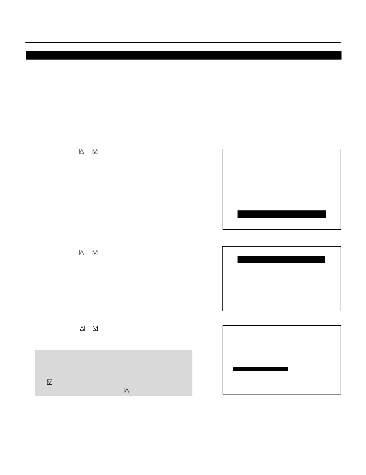
SETTING
Focus Edge Mode
This function allows you to set either of two electrical edge focus
modes; one affects all the RGB patterns at the same time and the
other each CRT separately.
To set this, proceed as follows:
1 Press the ADJUST button to display the “ADJUST” menu.
• The projector may ask you to enter your passcode.
See page 61 for the explanation of the PASSCODE.
2 Use the CURSOR or button to highlight the “8/OPTION”
line. Press ENTER to display the “OPTION” menu. You can also
select the “OPTION” menu directly by pressing the INPUT “8”
button.
3 Use the CURSOR or button to highlight the “1/SETTING
MODE” line. Press ENTER to display the “SETTING MODE”
menu. You can also select the “SETTING MODE” menu directly
by pressing the INPUT “1” button.
– ADJUST –
1 / SIGNAL ENTRY
2 / FOCUS
3 / ALIGNMENT
4 / CONVERGENCE
5 / KELVIN
6 / R,G,B GAIN
7 / PASSCODE
8 / OPTION
9 / REF.ADJUST
– OPTION –
1 / SETTING MODE
2 / MENU MODE
3 / SEQUENCER
4 / PJ ADDRESS
5 / VERSION
6 / HOUR METER
7 / DEFAULT DATA
4 Use the CURSOR or button to select the “FOCUS EDGE
MODE” item on Page 1, then press ENTER to display the
“FOCUS EDGE MODE” menu.
NOTE: The SETTING MODE has three menus. The “FOCUS
EDGE MODE” item is on the first menu (P01). To access P02 or
P03 from P01, press and hold down the CTL button then press
the button; to return to P01 from PO2 or P03, press and hold
down the CTL button then press the button.
76
P01/P03
PJ ORIENTATION
CONNECT CONDITION
DEFAULT INPUT SELECT
FOCUS EDGE MODE ALL
S-VIDEO MODE SELECT S2
VIDEO MODE SELECT AUTO
OPTION – SETTING MODE –
CEILING
FRONT
STANDALONE
LAST

5 Use the CURSOR or button to select either “ALL” or
“SEPARATE” and press ENTER.
Items to select
• ALL ...................... Affects all of the CRTs at the same time
• SEPARATE ...........Affects each CRT separately
6 To complete, press the END button.
• Whenever the END button is pressed, the menus will sequence
in this order:
“OPTION” menu → “ADJUST” menu → Source screen
• If the “RETURN USER MODE?” menu appears, use the
CURSOR or button to select either “YES” or “NO” and
press ENTER. This will exit the ADJUST mode.
Items to select
• YE S ......... When you try to enter the ADJUST mode the next
time, you will need to re-enter your passcode.
• NO ........... When you try to enter the ADJUST mode the next
time, you will not need to re-enter your passcode.
SETTING
FOCUS EDGE MODE
ALL
SEPARATE
RETURN USER MODE?
YES NO
77

SETTING
S-Video Mode Selection
This function is used to select the S-video signal detection mode.
This allows identifying of the S-video signals with different aspect
ratio: squeeze or full mode (CINEMA 16 : 9) and letter box (WIDE
4 : 3) signals.
To set, proceed as follows:
NOTE: An identifying result will be displayed in the SOURCE
INFORMATION screen.
1 Press the ADJUST button to display the “ADJUST” menu.
• The projector may ask you to enter your passcode.
See page 61 for the explanation of the PASSCODE.
2 Use the CURSOR or button to highlight the “8/OPTION”
line. Press ENTER to display the “OPTION” menu. You can also
select the “OPTION” menu directly by pressing the INPUT “8”
button.
3 Use the CURSOR or button to highlight the “1/SETTING
MODE” line. Press ENTER to display the “SETTING MODE”
menu. You can also select the “SETTING MODE” menu directly
by pressing the INPUT “1” button.
4 Use the CURSOR or button to select the “S-VIDEO MODE
SELECT” item, then press ENTER to display the “S-VIDEO
MODE SELECT” menu.
NOTE: The SETTING MODE has three menus. The “S-VIDEO
MODE SELECT” menu is on the first menu (P01). To access
P02 or P03 from P01, press and hold down the CTL button then
press the button; to return to P01 from P02 or P03, press
and hold down the CTL button then press the button.
– ADJUST –
1 / SIGNAL ENTRY
2 / FOCUS
3 / ALIGNMENT
4 / CONVERGENCE
5 / KELVIN
6 / R,G,B GAIN
7 / PASSCODE
8 / OPTION
9 / REF.ADJUST
– OPTION –
1 / SETTING MODE
2 / MENU MODE
3 / SEQUENCER
4 / PJ ADDRESS
5 / VERSION
6 / HOUR METER
7 / DEFAULT DATA
P01/P03
PJ ORIENTATION
CONNECT CONDITION
DEFAULT INPUT SELECT
FOCUS EDGE MODE ALL
S-VIDEO MODE SELECT S2
VIDEO MODE SELECT AUTO
OPTION – SETTING MODE –
CEILING
FRONT
STANDALONE
LAST
78

5 Use the CURSOR or button to select one of the three items:
S2, S1, and OFF, and then press ENTER.
Items to select
S2.............. Identifies squeeze and letter box signals.
S1.............. Identifies a squeeze signal only.
OFF ............ Does not identify any S-video signal.
6 To end, press the END button.
• Whenever the END button is pressed, the menus will sequence
in this order:
“OPTION” menu → “ADJUST” menu → Source screen
• If the “RETURN USER MODE?” menu appears, use the
CURSOR or button to select either “YES” or “NO” and
press ENTER. This will exit the ADJUST mode.
Items to select
• YE S ......... When you try to enter the ADJUST mode the next
time, you will need to re-enter your passcode.
• NO ........... When you try to enter the ADJUST mode the next
time, you will not need to re-enter your passcode.
SETTING
S-VIDEO MODE SELECT
S2
S1
OFF
RETURN USER MODE?
YES NO
NOTE :
• The input signal must be compatible with the S2/S1 MODE
standard.
Refer to the user manual included with the connected equipment for more information.
• The identification function may not work correctly with a non-
compatible signal. If this happens, select “OFF” from the “SVIDEO MODE SELECT” menu.
79

SETTING
Video Mode Selection
This function is used to select the NTSC 3.58, NTSC 4.43, PAL or
SECAM video standard.
To select any one of the video standards, proceed as follows:
1 Press the ADJUST button to display the “ADJUST” menu.
• The projector may ask you to enter your passcode.
See page 61 for the explanation of the PASSCODE.
2 Use the CURSOR or button to highlight the “8/OPTION”
line. Press ENTER to display the “OPTION” menu. You can also
select the “OPTION” menu directly by pressing the INPUT “8”
button.
3 Use the CURSOR or button to highlight the “1/SETTING
MODE” line. Press ENTER to display the “SETTING MODE”
menu. You can also select the “SETTING MODE” menu directly
by pressing the INPUT “1” button.
4 Use the CURSOR or button to select the “VIDEO MODE
SELECT” item, then press ENTER to display the “VIDEO
MODE SELECT” menu.
NOTE: The SETTING MODE has three menus. The “VIDEO
MODE SELECT” menu is on the first menu (P01). To access
P02 or P03 from P01, press and hold down the CTL button then
press the button; to return to P01 from P02 or P03, press
and hold down the CTL button then press the button.
– ADJUST –
1 / SIGNAL ENTRY
2 / FOCUS
3 / ALIGNMENT
4 / CONVERGENCE
5 / KELVIN
6 / R,G,B GAIN
7 / PASSCODE
8 / OPTION
9 / REF.ADJUST
– OPTION –
1 / SETTING MODE
2 / MENU MODE
3 / SEQUENCER
4 / PJ ADDRESS
5 / VERSION
6 / HOUR METER
7 / DEFAULT DATA
P01/P03
PJ ORIENTATION
CONNECT CONDITION
DEFAULT INPUT SELECT
FOCUS EDGE MODE ALL
S-VIDEO MODE SELECT S2
VIDEO MODE SELECT
OPTION – SETTING MODE –
CEILING
FRONT
STANDALONE
LAST
AUTO
80

5 Use the CURSOR or button to select either “AUTO” or
“MANUAL” and then press ENTER.
SETTING
When selecting “AUTO”
One of the video standards is selected automatically and is
displayed in the SOURCE INFORMATION screen.
Video Modes
• NTSC3.58 ............Indicates the NTSC3.58 video standard
• NTSC4.43 ............Indicates the NTSC4.43 video standard
• PA L .....................Indicates the PAL video standard
• SECAM ................Indicates the SECAM video standard
• RG B .....................Indicates the RGB mode
• Select “AUTO” in normal operation.
When selecting “MANUAL”
The “VIDEO MODE SELECT” menu will be displayed. Use the
CURSOR or button to select the preferred video mode and
then press ENTER.
Items to select
• NTSC3.58 Switches to the NTSC3.58 mode
• NTSC4.43 Switches to the NTSC4.43 mode
• PA L ......... Switches to the PAL mode
• SECAM .... Switches to the SECAM mode
VIDEO MODE SELECT
AUTO
MANUAL
VIDEO MODE SELECT
NTSC 3.58
NTSC 4.43
PAL
SECAM
• Select “MANUAL” when connecting to poor quality signal or
non-standard signals such as video games.
NOTE: The projector may not function correctly with a monochrome signals in the AUTO mode.
6 To complete, press the END button.
• Whenever the END button is pressed, the menus will sequence
in this order:
“OPTION” menu → “ADJUST” menu → Source screen
• When your passcode is in effect, the “RETURN USER
MODE?” menu is displayed. If this happens, use the
CURSOR or button to select either “YES” or “NO” and
press ENTER.
Items to select
• YE S ......... When you try to enter the ADJUST mode the next
time, you will need to re-enter your passcode.
• NO ........... When you try to enter the ADJUST mode the next
time, you will not need to re-enter your passcode.
RETURN USER MODE?
YES NO
81

SETTING
Auto Power ON Mode Setting
The AUTO POWER ON MODE is a convenient way to start up the
projector without pressing the POWER button. You can turn the
projector on and off by supplying AC power to the projector.
To do this, proceed as follows:
1 Press the ADJUST button to display the “ADJUST” menu.
• The projector may ask you to enter your passcode.
See page 61 for the explanation of the PASSCODE.
2 Use the CURSOR or button to highlight the “8/OPTION”
line. Press ENTER to display the “OPTION” menu. You can also
select the “OPTION” menu directly by pressing the INPUT “8”
button.
3 Use the CURSOR or button to highlight the “1/SETTING
MODE” line. Press ENTER to display the “SETTING MODE”
menu. You can also select the “SETTING MODE” menu directly
by pressing the INPUT “1” button.
4 Use the CURSOR or button to select the “AUTO POWER
ON MODE” item on Page 2, then press ENTER to display the
“AUTO POWER ON MODE” menu.
NOTE: The SETTING MODE has three menus. The “AUTO
POWER ON MODE” item is on the second menu (P02). To
access P02 from P01, press and hold down the CTL button then
press the button; to return to P01 from P02, press and hold
down the CTL button then press the button.
– ADJUST –
1 / SIGNAL ENTRY
2 / FOCUS
3 / ALIGNMENT
4 / CONVERGENCE
5 / KELVIN
6 / R,G,B GAIN
7 / PASSCODE
8 / OPTION
9 / REF.ADJUST
– OPTION –
1 / SETTING MODE
2 / MENU MODE
3 / SEQUENCER
4 / PJ ADDRESS
5 / VERSION
6 / HOUR METER
7 / DEFAULT DATA
P02/P03
AUTO POWER ON MODE
WARM-UP MODE
AUTOMATIC DATA STORE
PHOSPHOR SAVER OFF
SIGNAL SWITCHING SOUND
OPTION – SETTING MODE –
INACTIVE
INACTIVE
DISABLE
MUTE ON
PICTURE
MUTE ON
82

5 Use the CURSOR or button to select either “ACTIVE” or
“INACTIVE” and press the ENTER button.
SETTING
Items to select
• INACTIVE . Normal operation setting. Power ON is accomplished through the rear panel or the POWER
button on the remote control.
• ACTIVE .... Bypasses rear panel power button (or the POWER
button on the remote control) to allow power ON
to be controlled by an AC switched outlet.
6 To complete, press the END button.
• Whenever the END button is pressed, the menus will sequence
in this order:
“OPTION” menu → “ADJUST” menu → Source screen
• If the “RETURN USER MODE?” menu appears, use the
CURSOR or button to select either “YES” or “NO” and
then press ENTER.
Items to select
• YE S ......... When you try to enter the ADJUST mode the next
time, you will need to re-enter your passcode.
• NO ........... When you try to enter the ADJUST mode the next
time, you will not need to re-enter your passcode.
AUTO POWER ON MODE
INACTIVE
ACTIVE
RETURN USER MODE?
YES NO
83

SETTING
Warm-up Mode Setting
This function allows you to automatically warm up the projector
from 5 to 15 minutes when the projector is turned on.
To set the Warm-up mode, proceed as follows:
1 Press the ADJUST button to display the “ADJUST” menu.
• The projector may ask you to enter your passcode.
See page 61 for the explanation of the PASSCODE.
2 Use the CURSOR or button to highlight the “8/OPTION”
line. Press ENTER to display the “OPTION” menu. You can also
select the “OPTION” menu directly by pressing the INPUT “8”
button.
3 Use the CURSOR or button to highlight the “1/SETTING
MODE” line. Press ENTER to display the “SETTING MODE”
menu. You can also select the “SETTING MODE” menu directly
by pressing the INPUT “1” button.
– ADJUST –
1 / SIGNAL ENTRY
2 / FOCUS
3 / ALIGNMENT
4 / CONVERGENCE
5 / KELVIN
6 / R,G,B GAIN
7 / PASSCODE
8 / OPTION
9 / REF.ADJUST
– OPTION –
1 / SETTING MODE
2 / MENU MODE
3 / SEQUENCER
4 / PJ ADDRESS
5 / VERSION
6 / HOUR METER
7 / DEFAULT DATA
4 Use the CURSOR or button to select the “WARM-UP
MODE” item on Page 2, then press ENTER to display the
“WARM-UP MODE” menu.
NOTE: The SETTING MODE has three menus. The “WARM-UP
MODE” item is on the second menu (P02). To access P02 from
P01, press and hold down the CTL button then press
the button; to return to P01 from P02, press and hold down
the CTL button then press the button.
84
P02/P03
AUTO POWER ON MODE
WARM-UP MODE
AUTOMATIC DATA STORE
PHOSPHOR SAVER OFF
SIGNAL SWITCHING SOUND
OPTION – SETTING MODE –
INACTIVE
INACTIVE
DISABLE
MUTE ON
PICTURE
MUTE ON

5 Use the CURSOR or button to select either “ACTIVE” or
“INACTIVE” and press ENTER.
SETTING
Items to select
• INACTIVE . Displays the input source after the projector is
turned on.
• ACTIVE .... Activates the warm-up program after the projector
is turned on. The ALL WHITE test pattern will be
displayed. You can select a warm-up time from the
WARM-UP TIME menu.
NOTE: To interrupt and cancel the warm-up cycle, press the
END button.
6 To complete, press the END button.
• Whenever the END button is pressed, the menus will sequence
in this order:
“OPTION” menu → “ADJUST” menu → Source screen
• If the “RETURN USER MODE?” menu appears, use the
CURSOR or button to select either “YES” or “NO” and
then press ENTER.
Items to select
• YE S ......... When you try to enter the ADJUST mode the next
time, you will need to re-enter your passcode.
• NO ........... When you try to enter the ADJUST mode the next
time, you will not need to re-enter your passcode.
WARM-UP MODE
INACTIVE
ACTIVE
WARM-UP TIME
5 MIN
10 MIN
15 MIN
RETURN USER MODE?
YES NO
85

SETTING
Automatic Save Feature
This feature allows you to select two ways to store settings; automatically and manually.
After “ENABLE” is selected in the AUTOMATIC DATA STORE
menu, all projector settings are stored in the projector's memory
automatically. To set the AUTOMATIC DATA STORE, proceed as
follows:
1 Press the ADJUST button to display the “ADJUST” menu.
• The projector may ask you to enter your passcode.
See page 61 for the explanation of the PASSCODE section.
2 Use the CURSOR or button to highlight the “8/OPTION”
line and then press ENTER to display the “OPTION” menu. You
can also select the “OPTION” menu directly by pressing the
INPUT “8” button.
3 Use the CURSOR or button to highlight the “1/SETTING
MODE” line. Press ENTER to display the “SETTING MODE”
menu. You can also select the “SETTING MODE” menu directly
by pressing the INPUT “1” button.
– ADJUST –
1 / SIGNAL ENTRY
2 / FOCUS
3 / ALIGNMENT
4 / CONVERGENCE
5 / KELVIN
6 / R,G,B GAIN
7 / PASSCODE
8 / OPTION
9 / REF.ADJUST
– OPTION –
1 / SETTING MODE
2 / MENU MODE
3 / SEQUENCER
4 / PJ ADDRESS
5 / VERSION
6 / HOUR METER
7 / DEFAULT DATA
4 Use the CURSOR or button to select the “AUTOMATIC
DATA STORE” item on Page 2, then press ENTER to display
the “AUTOMATIC DATA STORE” menu.
NOTE: The SETTING MODE has three menus. The “AUTOMATIC
DATA STORE” item is on the second menu (P02). To access
P02 from P01, press and hold down the CTL button then press
the button ; to return to P01 from P02, press and hold down
the CTL button then press the button.
86
P02/P03
AUTO POWER ON MODE
WARM-UP MODE
AUTOMATIC DATA STORE
PHOSPHOR SAVER
SIGNAL SWITCHING SOUND
OPTION – SETTING MODE –
INACTIVE
INACTIVE
DISABLE
OFF
MUTE ON
PICTURE
MUTE ON

5 Use the CURSOR or button to select either “DISABLE” or
“ENABLE” and then press ENTER.
Items to select
• DISABLE .. Projector does not store the settings automatically.
• ENABLE ... Projector stores the settings automatically.
Automatic storing data is done when any one of the following
procedures is performed:
• Pressing the END button several times returns the adjustment
screen to the source screen.
• One input is switched to another.
• The projector is turned off.
• Every 10 minutes.
NOTE: After “DISABLE” is selected in the AUTOMATIC DATA
STORE menu, the settings will not be stored in the memory
unless you select “YES” in the “STORE ?” menu.
SETTING
AUTOMATIC DATA STORE
DISABLE
ENABLE
6 If the “RETURN USER MODE?” menu appears, use the
CURSOR or button to select either “YES” or “NO” and
press ENTER. This will exit the ADJUST mode.
Items to select
• YE S ......... When you try to enter the ADJUST mode the next
time, you will need to re-enter your passcode.
• NO ........... When you try to enter the ADJUST mode the next
time, you will not need to re-enter your passcode.
RETURN USER MODE?
YES NO
87

SETTING
Phosphor Saver Setting
This function allows you to safeguard the CRTs against burns by
shifting the image vertically and horizontally on the screen in the
regular intervals. This can prolong the life of CRT of the projector.
To set the Phosphor saver, proceed as follows:
1 Press the ADJUST button to display the “ADJUST” menu.
• The projector may ask you to enter your passcode.
See page 61 for the explanation of the PASSCODE.
2 Use the CURSOR or button to highlight the “8/OPTION”
line. Press ENTER to display the “OPTION” menu. You can also
select the “OPTION” menu directly by pressing the INPUT “8”
button.
3 Use the CURSOR or button to highlight the “1/SETTING
MODE” line. Press ENTER to display the “SETTING MODE”
menu. You can also select the “SETTING MODE” menu directly
by pressing the INPUT “1” button.
– ADJUST –
1 / SIGNAL ENTRY
2 / FOCUS
3 / ALIGNMENT
4 / CONVERGENCE
5 / KELVIN
6 / R,G,B GAIN
7 / PASSCODE
8 / OPTION
9 / REF.ADJUST
– OPTION –
1 / SETTING MODE
2 / MENU MODE
3 / SEQUENCER
4 / PJ ADDRESS
5 / VERSION
6 / HOUR METER
7 / DEFAULT DATA
4 Use the CURSOR or button to select the “PHOSPHOR
SAVER” item on Page 2, then press ENTER to display the
“PHOSPHOR SAVER” menu.
NOTE: The SETTING MODE has three menus. The “PHOSPHOR
SAVER” item is on the second menu (P02). To access P02 from
P01, press and hold down the CTL button then press
the button; to return to P01 from P02, press and hold down
the CTL button then press the button.
88
P02/P03
AUTO POWER ON MODE
WARM-UP MODE
AUTOMATIC DATA STORE
PHOSPHOR SAVER
SIGNAL SWITCHING SOUND
OPTION – SETTING MODE –
INACTIVE
INACTIVE
DISABLE
OFF
MUTE ON
PICTURE
MUTE ON

5 Use the CURSOR or button to select either “OFF” or “ON”
and press ENTER.
SETTING
Items to select
• OFF .......... Deactivates the PHOSPHOR SAVER function.
• ON ........... Activates the PHOSPHOR SAVER function. Interval
and number of steps can be set.
NOTE: When the on-screen display appears or you are in the
adjustment mode, this function is cancelled. This can cause the
source screen to be shifted.
6 Use the CURSOR or button to select your desired interval
time from the “INTERVAL” menu and press ENTER.
• The “STEP” menu is displayed on the screen.
Items to select
• DEMO (1 SEC) ........... Works every one second
• 5 MINUTES ............... Works every 5 minutes.
• 20 MINUTES ............. Works every 20 minutes
• 1 HOUR ..................... Works every 1 hour
PHOSPHOR SAVER
OFF
ON
INTERVAL
DEMO(1SEC)
5 MINUTES
20 MINUTES
1 HOUR
STEP
4 STEP
6 STEP
8 STEP
7 Use the CURSOR or button to select the number of steps
you wish.
Items to select
• 4 STEP .......Moves 4 steps of POSTIION adjustment value
• 6 STEP .......Moves 6 steps of POSITION adjustment value
• 8 STEP .......Moves 8 steps of POSITION adjustment value
8 To complete, press the END button.
• Whenever the END button is pressed, the menus will sequence
in this order:
“OPTION” menu → “ADJUST” menu → Source screen
• If the “RETURN USER MODE?” menu appears, use the
CURSOR or button to select either “YES” or “NO” and
then press ENTER.
Items to select
• YE S ......... When you try to enter the ADJUST mode the next
time, you will need to re-enter your passcode.
• NO ........... When you try to enter the ADJUST mode the next
time, you will not need to re-enter your passcode.
RETURN USER MODE?
YES NO
89

SETTING
Signal Switching Mute Mode Setting
This function allows you to mute the picture and/or sound during
signal switching.
To set the Signal Switching Mute mode, proceed as follows:
1 Press the ADJUST button to display the “ADJUST” menu.
• The projector may ask you to enter your passcode.
See page 61 for the explanation of the PASSCODE.
2 Use the CURSOR or button to highlight the “8/OPTION”
line. Press ENTER to display the “OPTION” menu. You can also
select the “OPTION” menu directly by pressing the INPUT “8”
button.
3 Use the CURSOR or button to highlight the “1/SETTING
MODE” line. Press ENTER to display the “SETTING MODE”
menu. You can also select the “SETTING MODE” menu directly
by pressing the INPUT “1” button.
– ADJUST –
1 / SIGNAL ENTRY
2 / FOCUS
3 / ALIGNMENT
4 / CONVERGENCE
5 / KELVIN
6 / R,G,B GAIN
7 / PASSCODE
8 / OPTION
9 / REF.ADJUST
– OPTION –
1 / SETTING MODE
2 / MENU MODE
3 / SEQUENCER
4 / PJ ADDRESS
5 / VERSION
6 / HOUR METER
7 / DEFAULT DATA
4 Use the CURSOR or button to select the “SIGNAL
SWITCHING” item on Page 2, then press ENTER to display the
“SIGNAL SWITCHING” menu.
NOTE: The SETTING MODE has three menus. The “SIGNAL
SWITCHING” menu is on the second menu (P02). To access
P02 from P01, press and hold down the CTL button then press
the button; to return to P01 from P02, press and hold down
the CTL button then press the button.
90
P02/P03
AUTO POWER ON MODE
WARM-UP MODE
AUTOMATIC DATA STORE
PHOSPHOR SAVER
SIGNAL SWITCHING SOUND
OPTION – SETTING MODE –
INACTIVE
INACTIVE
DISABLE
OFF
MUTE ON
PICTURE
MUTE ON

5 Use the CURSOR or button to select either “SOUND” or
“PICTURE”, and press the ENTER button.
• The “SOUND MUTE” or “PICTURE MUTE” menu will be
displayed.
6 Use the CURSOR or button to select either “ON” or “OFF”
and then press ENTER.
Items to select
MUTE ON... Mutes a picture and/or sound during switching
signals.
MUTE OFF.. Outputs a picture and/or sound during switching
signals.
SETTING
SIGNAL SWITCHING MUTE
SOUND
PICTURE
SOUND MUTE
ON
OFF
ON
ON
7 To complete this, press END.
• Whenever the END button is pressed, the menus will sequence
in this order:
“OPTION” menu → “ADJUST” menu → Source screen
• If the “RETURN USER MODE?” menu appears, use the
CURSOR or button to select either “YES” or “NO” and
then press ENTER.
Items to select
• YES ......... When you try to enter the ADJUST mode the next
time, you will need to re-enter your passcode.
• NO ........... When you try to enter the ADJUST mode the next
time, you will not need to re-enter your passcode.
RETURN USER MODE?
YES NO
91

SETTING
Direct Entry Access Setting
This feature allows you to switch the current input directly to one of
the registered inputs from NO1 to NO10 in the INPUT LIST.
NOTE: To use this feature, hold down the CTL button and press one
of the INPUT buttons corresponding to the input number.
To set this feature, proceed as follows:
1 Press the ADJUST button to display the “ADJUST” menu.
• The projector may ask you to enter your passcode.
See page 61 for the explanation of the PASSCODE.
2 Use the CURSOR or button to highlight the “8/OPTION”
line. Press ENTER to display the “OPTION” menu. You can also
select the “OPTION” menu directly by pressing the INPUT “8”
button.
3 Use the CURSOR or button to highlight the “1/SETTING
MODE” line. Press ENTER to display the “SETTING MODE”
menu. You can also select the “SETTING MODE” menu directly
by pressing the INPUT “1” button.
– ADJUST –
1 / SIGNAL ENTRY
2 / FOCUS
3 / ALIGNMENT
4 / CONVERGENCE
5 / KELVIN
6 / R,G,B GAIN
7 / PASSCODE
8 / OPTION
9 / REF.ADJUST
– OPTION –
1 / SETTING MODE
2 / MENU MODE
3 / SEQUENCER
4 / PJ ADDRESS
5 / VERSION
6 / HOUR METER
7 / DEFAULT DATA
4 Use the CURSOR or button to select the “DIRECT ENTRY
ACCESS” item on Page 3, then press ENTER to display the
“DIRECT ENTRY ACCESS” menu.
NOTE: The SETTING MODE has three menus. The “DIRECT
ENTRY ACCESS” item is on the third menu (P03).
To access P03 from P01, press and hold down the CTL button
then press the button twice; to return to P01 from P03, press
and hold down the CTL button then press the button twice.
92
P03/P03
DIRECT ENTRY ACCESS
B-FOCUS TRACKING
OPTION TERM BAUD RATE
INPUT TERMINAL
RGB/COMPONENT SEARCH
OPTION – SETTING MODE –
DISABLE
OFF
9600 BPS
MANUAL
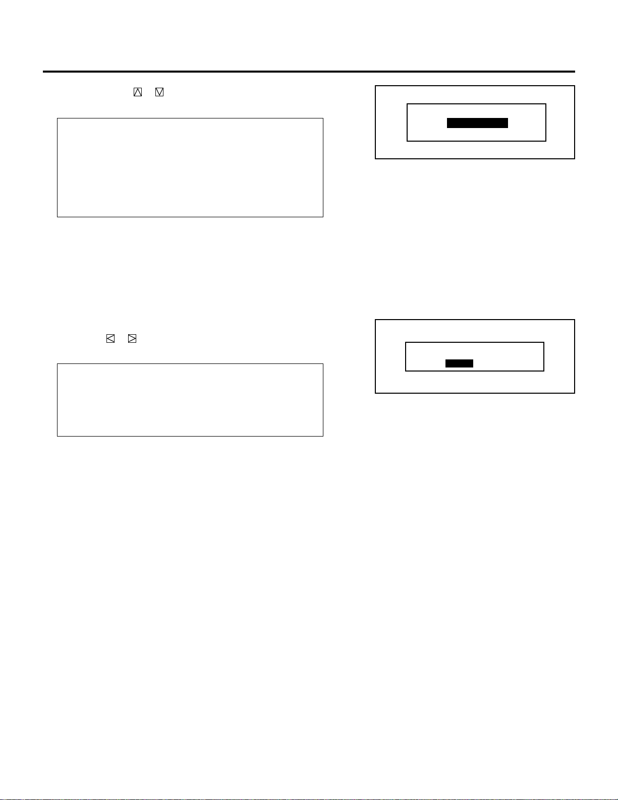
5 Use the CURSOR or button to select either “DISABLE” or
“ENABLE” and press ENTER.
Items to select
• DISABLE.. An error message will appear at the bottom of the
screen and the signal is not switched when one of
the INPUT buttons is pressed with CTL.
• ENABLE... The signal is switched to the corresponding signal
when one of the INPUT button is pressed with
CTL.
6 To complete this, press END.
• Whenever the END button is pressed, the menus will sequence
in this order.
“OPTION” menu → “ADJUST” menu → Source screen
• If the RETURN USER MODE ? menu appears, use the
CURSOR or button to select either “YES” or “NO” and
press ENTER. This will exit the ADJUST mode.
Items to select
• YES ......... When you try to enter the ADJUST mode the next
time, you will need to re-enter your passcode.
• NO ........... When you try to enter the ADJUST mode the next,
you will not need to re-enter your passcode.
SETTING
DIRECT ENTRY ACCESS
DISABLE
ENABLE
RETURN USER MODE?
YES NO
93

SETTING
Blue Focus Tracking Setting
This feature allows you to obtain the better white uniformity by
defocusing the blue CRT.
NOTE:
• The defocus values will vary with changes in the horizontal
frequency.
• Select the “ALL WHITE” pattern using the TEST button on the full
function remote control.
1 Press the ADJUST button to display the “ADJUST” menu.
• The projector may ask you to enter your passcode.
See page 61 for the explanation of PASSCODE.
2 Use the CURSOR or button to highlight the “8/OPTION”
line. Press ENTER to display the “OPTION” menu. You can also
select the “OPTION” menu directly by pressing the INPUT “8”
button.
3 Use the CURSOR or button to highlight the “1/SETTING
MODE” line. Press ENTER to display the “SETTING MODE”
menu. You can also select the “SETTING MODE” menu directly
by pressing the INPUT “1” button.
4 Use the CURSOR or button to select the “B-FOCUS
TRACKING” item on Page 3, then press ENTER to display the
“B-FOCUS TRACKING” menu.
NOTE: The SETTING MODE has three menus. The “B-FOCUS
TRACKING” item is on the third menu (P03). To access P03
from P01, press and hold down the CTL button then press the
button twice; to return to P01 from P03, press and hold
down the CTL button then press the button twice.
5 Use the CURSOR or button to select either “OFF” or
“ON” and press ENTER.
Items to select
•OFF ...... Defocuses the blue CRT
•ON ....... Does not defocus the blue CRT
– ADJUST –
1 / SIGNAL ENTRY
2 / FOCUS
3 / ALIGNMENT
4 / CONVERGENCE
5 / KELVIN
6 / R,G,B GAIN
7 / PASSCODE
8 / OPTION
9 / REF.ADJUST
– OPTION –
1 / SETTING MODE
2 / MENU MODE
3 / SEQUENCER
4 / PJ ADDRESS
5 / VERSION
6 / HOUR METER
7 / DEFAULT DATA
P03/P03
DIRECT ENTRY ACCESS
B-FOCUS TRACKING
OPTION TERM BAUD RATE
RGB/COMPONENT SEARCH
OPTION – SETTING MODE –
DISABLE
OFF
9600 BPS
MANUAL
6 To end this mode, press the END button.
• Whenever the END button is pressed, the menu will sequence in
this order.
“OPTION” menu→”ADJUST” menu→Source screen.
• If the “RETURN USER MODE?” menu appears, use the
CURSOR or button to select either “YES” or “NO” and
then press ENTER. This will exit the ADJUST mode.
Items to select
•YES...... When you try to enter the ADJUST mode the next time,
you will need to re-enter your passcode.
•NO ....... When you try to enter the ADJUST mode the next time,
you will not need to re-enter your passcode.
B-FOCUS TRACKING
OFF
ON
RETURN USER MODE?
YES NO
94

Optional Terminal Baud Rate Selection
This feature allows you to set baud rate of the OPTION terminal
from 4800 to 38400 bps.
NOTE:
• The baud rate of the OPTION terminal defaults to 9600 bps at the
factory.
• Make sure that the baud rate of the OPTION terminal matches that
of operating of the connected equipment.
SETTING
To change the baud rate of the OPTION terminal, proceed as follows:
1 Press the ADJUST button to display the “ADJUST” menu.
• The projector may ask you to enter your passcode.
See page 61 for the explanation of PASSCODE.
2 Use the CURSOR or button to highlight the “8/OPTION”
line. Press ENTER to display the “OPTION” menu. You can also
select the “OPTION” menu directly by pressing the INPUT “8”
button.
3 Use the CURSOR or button to highlight the “1/SETTING
MODE” line. Press ENTER to display the “SETTING MODE”
menu. You can also select the “SETTING MODE” menu directly
by pressing the INPUT “1” button.
4 Use the CURSOR or button to select the “OPTION
TERM BAUD RATE” item on Page 3, then press ENTER to
display the “OPTION TERM BAUD RATE” menu.
NOTE: The SETTING MODE has three menus. The “OPTION
TERM BAUD RATE” item is on the third menu (P03). To access
P03 from P01, press and hold down the CTL button then press
the button twice; to return to P01 from P03, press and hold
down the CTL button then press the button twice.
5 Use the CURSOR or button to select the baud rate from
4800 to 38400 bps and press ENTER.
– ADJUST –
1 / SIGNAL ENTRY
2 / FOCUS
3 / ALIGNMENT
4 / CONVERGENCE
5 / KELVIN
6 / R,G,B GAIN
7 / PASSCODE
8 / OPTION
9 / REF.ADJUST
– OPTION –
1 / SETTING MODE
2 / MENU MODE
3 / SEQUENCER
4 / PJ ADDRESS
5 / VERSION
6 / HOUR METER
7 / DEFAULT DATA
P03/P03
DIRECT ENTRY ACCESS
B-FOCUS TRACKING
OPTION TERM BAUD RATE
RGB/COMPONENT SEARCH
OPTION – SETTING MODE –
DISABLE
OFF
9600 BPS
MANUAL
6 To end this mode, press the END button.
• Whenever the END button is pressed, the menu will sequence
in this order.
“OPTION” menu→”ADJUST” menu→Source screen.
• IF the “RETURN USER MODE?” menu appears, use the
CURSOR or button to select either “YES” or “NO” and
then press ENTER. This will exit the ADJUST mode.
Items to select
•YES...... When you try to enter the ADJUST mode the next time,
you will need to re-enter your passcode.
•NO ....... When you try to enter the ADJUST mode the next time,
you will not need to re-enter your passcode.
OPTION TERM.
BAUD RATE
4800
9600
19200
38400
RETURN USER MODE?
YES NO
95

SETTING
RGB/COMPONENT Search Setting
This feature allows you to set the searching method of RGB/
COMPONENT signal.
To set this feature, proceed as follows:
1 Press the ADJUST button to display the “ADJUST” menu.
• The projector may ask you to enter your passcode.
See page 61 for the explanation of PASSCODE.
2 Use the CURSOR or button to highlight the “8/OP-
TION” line. Press ENTER to display the “OPTION” menu. You
can also select the “OPTION” menu directly by pressing the
INPUT “8” button.
3 Use the CURSOR or button to highlight the “1/SET-
TING MODE” line. Press ENTER to display the “SETTING
MODE” menu. You can also select the “SETTING MODE”
menu directly by pressing the INPUT “1” button.
4 Use the CURSOR or button to select “RGB/COMPO-
NENT SEARCH” item on Page 3, then press ENTER to display
the “RGB/COMPONENT SEARCH” menu.
NOTE: The SETTING MODE has three menus. The “RGB/
COMPONENT SEARCH” item is on the third menu (P03). To
access P03 from P01, press and hold down the CTL button then
press the v button twice; to return to P01 from P03, press and
hold down the CTL button then press the button twice.
5 Use the CURSOR or button to select either “MANUAL”
or “AUTO” and press ENTER.
When used in a stand alone operation:
Items to select
*MANUAL ............ Searches RGB signals only
*AUTO.................. Searches COMPONENT signals automati-
cally after searching RGB signals.
– ADJUST –
1 / SIGNAL ENTRY
2 / FOCUS
3 / ALIGNMENT
4 / CONVERGENCE
5 / KELVIN
6 / R,G,B GAIN
7 / PASSCODE
8 / OPTION
9 / REF.ADJUST
– OPTION –
1 / SETTING MODE
2 / MENU MODE
3 / SEQUENCER
4 / PJ ADDRESS
5 / VERSION
6 / HOUR METER
7 / DEFAULT DATA
P03/P03
DIRECT ENTRY ACCESS
B-FOCUS TRACKING
OPTION TERM BAUD RATE
RGB/COMPONENT SEARCH
OPTION – SETTING MODE –
DISABLE
OFF
9600 BPS
MANUAL
NOTE: This feature corresponds to R/Cr, G/Y, or B/Cb input
terminal of INPUT A slot. INPUT B and C slots are depending on
setting of the optional input board.
In regardless of this setting, pressing INPUT “10” button
searches a COMPONENT signal.
96
RGB/COMPONENT SEARCH
MANUAL
AUTO

When used with a single Switcher ISS-6020/ISS-6020G:
SLOT–01
SLOT–02
SLOT–03
SLOT–04
SLOT–05
SLOT–06
SLOT–07
SLOT–08
SLOT–09
SLOT–10
R
R
R
R
R
R
R
R
R
R
MASTER
Items to select
• MANUAL .............Searches RGB or COMPONENT signals only.
• AUTO................... Searches COMPONENT signals automatically
after searching RGB signals.
• When “MANUAL” is selected, searching will be set for each
slot.
Use the CURSOR or button to select the input slot
number of the Switcher and press ENTER.
• The “SIGNAL FORMAT” menu will be displayed.
Use the CURSOR or button to select “RGB” or “COMPONENT” and press ENTER.
When used with two or more Switchers ISS-6020/ISS-6020G:
Items to select
• MANUAL ....... Searches RGB or COMPONENT signals only
( for each slot).
• AUTO............. Searches COMPONENT signals automatically
after searching RGB signals ( for all slots).
SETTING
SIGNAL FORMAT
RGB
COMPONENT
• When “MANUAL” is selected, searching will be set for each
slot.
Use the CURSOR or button to select the master slot
number “1” through “10” first from the master menu, then
select the slave slot number “1” through “10” from the slave
menu and press ENTER.
• The “SIGNAL FORMAT” menu will be displayed.
Use the CURSOR or button to select “RGB” or “COMPONENT” and press ENTER.
Items to select
RGB ....................... Searches RGB signals only.
COMPONENT ......... Searches COMPONENT signals only.
6 To end this mode, press the END button.
• Whenever the END button is pressed, the menu will
sequence in this order.
“OPTION” menu → ”ADJUST” menu → Source screen
• If the “RETURN USER MODE?” menu appears, use the
CURSOR or button to select either “YES” or “NO” and
then press ENTER. This will exit the ADJUST mode.
Items to select
• YES .....When you try to enter the ADJUST mode the next time,
you will need to re-enter your passcode.
• NO.......When you try to enter the ADJUST mode the next time,
you will not need to re-enter your passcode.
MASTER
SLOT–01
SLOT–02
SLOT–03
SLOT–04
SLOT–05
SLOT–06
SLOT–07
SLOT–08
SLOT–09
SLOT–10
MASTER
SLOT–01
SLOT–02
SLOT–03
SLOT–04
SLOT–05
SLOT–06
SLOT–07
SLOT–08
SLOT–09
SLOT–10
SIGNAL FORMAT
RGB
COMPONENT
RETURN USER MODE?
YES NO
R
R
R
R
R
R
R
R
R
R
97

SETTING
On-screen Display Mode Setting
There are two modes of operations for the on-screen display. With
AUTO mode, the on-screen display will automatically switch off
after three through ten seconds. In the MANUAL mode, the display
must be manually turned off with the DISPLAY button on the full
function remote control each time it appears.
NOTE: Pressing DISPLAY with CTL will select the non on-screen
mode; pressing DISPLAY with CTL again will cancel this mode.
Even if the on-screen display may be turned off with CTL and
DISPLAY, any adjustment will still change the projector’s memory
settings.
Proceed as follows:
1 Press the ADJUST button to display the “ADJUST” menu.
• The projector may ask you to enter your passcode.
See page 61 for the explanation of the PASSCODE.
2 Use the CURSOR or button to highlight the “8/OPTION”
line. Press ENTER to display the “OPTION” menu. You can also
select the “OPTION” menu directly by pressing the INPUT “8”
button.
3 Use the CURSOR or button to highlight the “2/MENU
MODE” line. Press ENTER to display the “MENU MODE”
menu. You can also select the “MENU MODE” menu directly by
pressing the INPUT “2” button.
4 Use the CURSOR or button to highlight the “MESSAGE
MODE” item.
Press ENTER to display the “MESSAGE MODE” menu.
– ADJUST –
1 / SIGNAL ENTRY
2 / FOCUS
3 / ALIGNMENT
4 / CONVERGENCE
5 / KELVIN
6 / R,G,B GAIN
7 / PASSCODE
8 / OPTION
9 / REF.ADJUST
– OPTION –
1 / SETTING MODE
2 / MENU MODE
3 / SEQUENCER
4 / PJ ADDRESS
5 / VERSION
6 / HOUR METER
7 / DEFAULT DATA
OPTION - MENU MODE -
MESSAGE MODE
MESSAGE COLOR
AUTO
10 SEC
COLOR
98
DATE, TIME DISPLAY
DATE : MM/DD/YY
TIME : 24HOUR
DATE, TIME PRESET
PJ ADDRESS DISPLAY
NEW SIGNAL MESSAGE
DATE : ON
DAY : OFF
TIME : ON
OFF
ON

5 Use the CURSOR or button to select either “AUTO” or
“MANUAL“ and press ENTER.
SETTING
Items to select
• AUTO....... The on-screen menu display appears when the
buttons on the remote control, or the controls on
the rear panel are pressed. The on-screen display
will turn off at a preselected time.
The OFF TIME is specified in seconds up to a
maximum of 10 seconds.
Select your desired time (3-10 seconds) from the
OFF TIME menu.
• MANUAL . The on-screen menu display appears when the
buttons on the remote control, or the controls on
the rear panel are pressed. The display will be
turned on and off whenever the DISPLAY button is
pressed. If no button operation is made for 20
minutes or more, the on-screen message will
automatically turn off.
6 To end this mode, press the END button.
• When the END button is pressed, the menus will sequence in
this order:
“OPTION” menu → “ADJUST” menu → Source screen
• If the “RETURN USER MODE?” menu appears, use the
CURSOR or button to select either “YES” or “NO” and
press ENTER. This will exit the ADJUST mode.
Items to select
• YES ......... When you try to enter the ADJUST mode the next
time, you will need to re-enter your passcode.
• NO ........... When you try to enter the ADJUST mode the next
time, you will not need to re-enter your passcode.
MESSAGE MODE
AUTO
MANUAL
OFF TIME?
3 SEC
4 SEC
5 SEC
6 SEC
7 SEC
8 SEC
9 SEC
10 SEC
RETURN USER MODE?
YES NO
99

SETTING
On-screen Display Color Setting
You can select two color modes (full color, or green only) for the
color of the on-screen display such as menus, or messages.
Proceed as follows:
1 Press the ADJUST button to display the “ADJUST” menu.
• The projector may ask you to enter your passcode.
See page 61 for the explanation of the PASSCODE.
2 Use the CURSOR or button to highlight the “8/OPTION”
line. Press ENTER to display the “OPTION” menu. You can also
select the “OPTION” menu directly by pressing the INPUT “8”
button.
3 Use the CURSOR or button to highlight the “2/MENU
MODE” line. Press ENTER to display the “MENU MODE”
menu. You can also select the “MENU MODE” menu directly by
pressing the INPUT “2” button.
– ADJUST –
1 / SIGNAL ENTRY
2 / FOCUS
3 / ALIGNMENT
4 / CONVERGENCE
5 / KELVIN
6 / R,G,B GAIN
7 / PASSCODE
8 / OPTION
9 / REF.ADJUST
– OPTION –
1 / SETTING MODE
2 / MENU MODE
3 / SEQUENCER
4 / PJ ADDRESS
5 / VERSION
6 / HOUR METER
7 / DEFAULT DATA
4 Use the CURSOR or button to highlight the “MESSAGE
COLOR” item.
Press ENTER to display the “MESSAGE COLOR” menu.
100
OPTION - MENU MODE -
MESSAGE MODE
MESSAGE COLOR
DATE, TIME DISPLAY
DATE : MM/DD/YY
TIME : 24HOUR
DATE, TIME PRESET
PJ ADDRESS DISPLAY
NEW SIGNAL MESSAGE
AUTO
10 SEC
COLOR
DATE : ON
DAY : OFF
TIME : ON
OFF
ON

5 Use the CURSOR or button to select either “COLOR” or
“GREEN“ and press ENTER.
SETTING
Items to select
• COLOR .... The on-screen characters will be displayed in
color.
• GREEN..... The on-screen characters will be displayed only in
green.
NOTE: It is recommended, if the on-screen message interferes
with the display image in the “COLOR” mode, that you select
“GREEN”.
6 To end this mode, press the END button.
• Whenever the END button is pressed, the menus will sequence
in this order:
“OPTION” menu → “ADJUST” menu → Source screen
• If the “RETURN USER MODE?” menu appears, use the
CURSOR or button to select either “YES” or “NO” and
press ENTER. This will exit the ADJUST mode.
Items to select
• YES ......... When you try to enter the ADJUST mode the next
time, you will need to re-enter your passcode.
• NO ........... When you try to enter the ADJUST mode the next
time, you will not need to re-enter your passcode.
MESSAGE COLOR
COLOR
GREEN
RETURN USER MODE?
YES NO
101
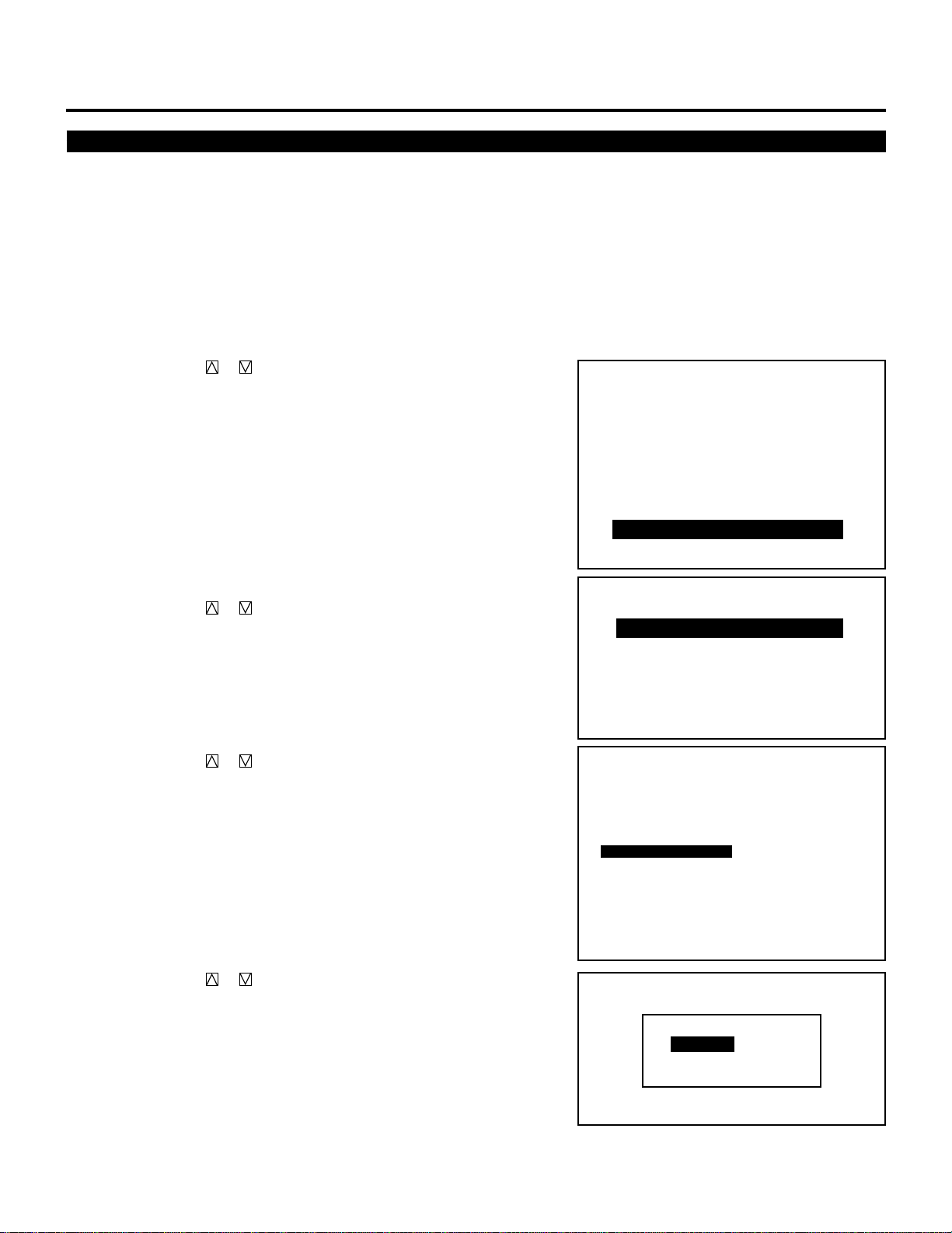
SETTING
Date, Time Display Setting
The current year, month, date and time are displayed on the top of
the screen.
Proceed as follows:
1 Press the ADJUST button to display the “ADJUST” menu.
• The projector may ask you to enter your passcode.
See page 61 for the explanation of the PASSCODE.
2 Use the CURSOR or button to highlight the “8/OPTION”
line. Press ENTER to display the “OPTION” menu. You can also
select the “OPTION” menu directly by pressing the INPUT “8”
button.
3 Use the CURSOR or button to highlight the “2/MENU
MODE” line. Press ENTER to display the “MENU MODE”
menu. You can also select the “MENU MODE” menu directly by
pressing the INPUT “2” button.
4 Use the CURSOR or button to highlight the “DATE, TIME,
DISPLAY” item. Press ENTER to display the “DATE, TIME
DISPLAY” menu.
– ADJUST –
1 / SIGNAL ENTRY
2 / FOCUS
3 / ALIGNMENT
4 / CONVERGENCE
5 / KELVIN
6 / R,G,B GAIN
7 / PASSCODE
8 / OPTION
9 / REF.ADJUST
– OPTION –
1 / SETTING MODE
2 / MENU MODE
3 / SEQUENCER
4 / PJ ADDRESS
5 / VERSION
6 / HOUR METER
7 / DEFAULT DATA
OPTION - MENU MODE -
MESSAGE MODE
MESSAGE COLOR
AUTO
10 SEC
COLOR
5 Use the CURSOR or button to select any one of the three
items: DATE, DAY, and TIME. Then press ENTER.
102
DATE, TIME DISPLAY
DATE : MM/DD/YY
TIME : 24HOUR
DATE, TIME PRESET
PJ ADDRESS DISPLAY
NEW SIGNAL MESSAGE
DATE,TIME DISPLAY
DATE
DAY
TIME
ON
OFF
ON
DATE : ON
DAY : OFF
TIME : ON
OFF
ON

m When selecting “DATE”
OFF
ON
DAY DISPLAY
Use the CURSOR or button to select any one of the three
formats: MM/DD/YY, MONTH/ DD/YY, or OFF from the
“DATE DISPLAY” menu and press ENTER.
Items to select
• MM/DD/YY ..........Is the date in month/day-of-month/year
format.
• MONTH/DD/YY.... Is the date in month (not in Arabic numer-
als)/day-of-month/year format.
• OFF...................... Does not display the date.
m When selecting “DAY”
Use the CURSOR or button to select either “ON” or “OFF”
from the “DAY DISPLAY” menu and press ENTER.
Items to select
• OFF...................... Does not display the day of the week
• ON .......................Displays the day of the week
SETTING
DATE DISPLAY
MM/DD/YY
MONTH/DD/YY
OFF
m When selecting “TIME”
Use the CURSOR or button to select any one of the three
items: HH/MM/SS AM/PM, HH/MM/SS 24 HOUR, or OFF
from the “TIME DISPLAY” menu and press ENTER.
Items to select
•
HH:MM:SS AM/PM
•
HH:MM:SS 24 HOUR
• OFF...................... Does not display the time.
NOTE: You can select the time input format for timer, date,
preset with this feature. When OFF is selected, use the AM/PM
format.
6 To end this mode, press END.
• Whenever the END button is pressed, the menus will sequence
in this order:
“OPTION” menu → “ADJUST” menu → Source screen
• If the “RETURN USER MODE?” menu appears, use the
CURSOR or button to select either “YES” or “NO” and
press ENTER. This will exit the ADJUST mode.
Items to select
• YES ..................... When you try to enter the ADJUST mode
• NO .......................When you try to enter the ADJUST mode
TIME DISPLAY
HH:MM:SS AM/PM
HH:MM:SS 24HOUR
OFF
....Is the time in hours/minutes/seconds/am/
pm. format
.....Is the time in hours/minutes/seconds/24-
hour format
RETURN USER MODE?
YES NO
the next time, you will need to re-enter your
passcode.
the next time, you will not need to re-enter
your passcode.
103

SETTING
Entering Date and Time
You can enter the year, date and time to display them on the screen.
Proceed as follows:
1 Press the ADJUST button to display the “ADJUST” menu.
• The projector may ask you to enter your passcode.
See page 61 for the explanation of the PASSCODE.
2 Use the CURSOR or button to highlight the “8/OPTION”
line. Press ENTER to display the “OPTION” menu. You can also
select the “OPTION” menu directly by pressing the INPUT “8”
button.
3 Use the CURSOR or button to highlight the “2/MENU
MODE” line. Press ENTER to display the “MENU MODE”
menu. You can also select the “MENU MODE” menu directly by
pressing the INPUT “2” button.
– ADJUST –
1 / SIGNAL ENTRY
2 / FOCUS
3 / ALIGNMENT
4 / CONVERGENCE
5 / KELVIN
6 / R,G,B GAIN
7 / PASSCODE
8 / OPTION
9 / REF.ADJUST
– OPTION –
1 / SETTING MODE
2 / MENU MODE
3 / SEQUENCER
4 / PJ ADDRESS
5 / VERSION
6 / HOUR METER
7 / DEFAULT DATA
4 Use the CURSOR or button to highlight the “DATE, TIME
PRESET” item. Press ENTER to display the “DATE, TIME
PRESET” menu.
104
OPTION - MENU MODE -
MESSAGE MODE
MESSAGE COLOR
DATE, TIME DISPLAY
DATE : MM/DD/YY
TIME : 24HOUR
DATE, TIME PRESET
PJ ADDRESS DISPLAY
NEW SIGNAL MESSAGE
AUTO
10 SEC
COLOR
DATE : ON
DAY : OFF
TIME : ON
OFF
ON

5 Use INPUT buttons to enter the year, month, day, hour, minute,
and second and press ENTER.
• Pressing the END button will turn off the “DATE, TIME
PRESET” screen and the screen will return to the “MENU
MODE” menu.
• If you made an error in entering data, press the END button to
return to the “MENU MODE” menu, then start again.
• The time input format varies depending on the setting previously explained.
6 To end this mode, press END.
• Whenever the END button is pressed, the menus will sequence
in this order:
“OPTION” menu → “ADJUST” menu → Source screen
• If the “RETURN USER MODE?” menu appears, use the
CURSOR or button to select either “YES” or “NO” and
press ENTER. This will exit the ADJUST mode.
DATE,TIME PRESET
DATE
TIME
RETURN USER MODE?
(MM/DD/YY)
__/__/__(MON)
(HH:MM:SS)
__:__:__
YES NO
SETTING
Items to select
• YES ......... When you try to enter the ADJUST mode the next
time, you will need to re-enter your passcode.
• N O ........... When you try to enter the ADJUST mode the next
time, you will not need to re-enter your passcode.
NOTE: The projector has a built-in clock. The clock will keep
working for about three days after the main power is turned off.
If the main power is not supplied to the projector for three days
or more, the built-in clock may reset. If the built-in clock resets,
set the date and time again. The built-in clock will not reset
while in the standby condition.
105

SETTING
PJ Address Display Setting
This feature allows you to view the PJ address on the screen.
To set the PJ address display, proceed as follows:
1 Press the ADJUST button to display the “ADJUST” menu.
• The projector may ask you to enter your passcode.
See page 61 for the explanation of PASSCODE.
2 Use the CURSOR or button to highlight the “8/OPTION”
line. Press ENTER to display the “OPTION” menu. You can also
select the “OPTION” menu directly by pressing the INPUT “8”
button.
– ADJUST –
1 / SIGNAL ENTRY
2 / FOCUS
3 / ALIGNMENT
4 / CONVERGENCE
5 / KELVIN
6 / R,G,B GAIN
7 / PASSCODE
8 / OPTION
9 / REF.ADJUST
3 Use the CURSOR or button to highlight the “2/MENU
MODE” line. Press ENTER to display the “MENU MODE”
menu. You can also select the “MENU MODE” menu directly by
pressing the INPUT “2” button.
4 Use the CURSOR or button to highlight the “NEW
SIGNAL MESSAGE” item. Press ENTER to display the “PJ
ADDRESS DISPLAY” menu.
5 Use the CURSOR or button to select either “OFF” or
“ON”, and press ENTER.
Items to select
• OFF .......... Does not display PJ address
• ON ........... Displays PJ address
6 To end this mode, press END.
• Whenever the END button is pressed, the menu will sequence in
this order.
“OPTION” menu→”ADJUST” menu→Source screen.
• If the “RETURN USER MODE?” menu appears, use the
CURSOR or button to select either “YES” or “NO” and
then press ENTER. This will exit the ADJUST mode.
– OPTION –
1 / SETTING MODE
2 / MENU MODE
3 / SEQUENCER
4 / PJ ADDRESS
5 / VERSION
6 / HOUR METER
7 / DEFAULT DATA
OPTION - MENU MODE -
MESSAGE MODE
MESSAGE COLOR
DATE, TIME DISPLAY
DATE : MM/DD/YY
TIME : 24HOUR
DATE, TIME PRESET
PJ ADDRESS DISPLAY
NEW SIGNAL MESSAGE
PJ ADDRESS DISPLAY
OFF
ON
AUTO
10 SEC
COLOR
DATE : ON
DAY : OFF
TIME : ON
OFF
ON
Items to select
• YES ......... When you try to enter the ADJUST mode again,
you will need to re-enter your passcode.
• NO ........... When you try to enter the ADJUST mode again,
you will not need to re-enter your passcode.
RETURN USER MODE?
YES NO
106

"NEW SIGNAL" Message Display Setting
This feature allows you to view the "NEW SIGNAL" message when
an unregistered signal is projected.
SETTING
To set the PJ address display, proceed as follows:
1 Press the ADJUST button to display the “ADJUST” menu.
• The projector may ask you to enter your passcode.
See page 61 for the explanation of PASSCODE.
2 Use the CURSOR or button to highlight the “8/OPTION”
line. Press ENTER to display the “OPTION” menu. You can also
select the “OPTION” menu directly by pressing the INPUT “8”
button.
3 Use the CURSOR or button to highlight the “2/MENU
MODE” line. Press ENTER to display the “MENU MODE”
menu. You can also select the “MENU MODE” menu directly by
pressing the INPUT “2” button.
4 Use the CURSOR or button to highlight the “NEW
SIGNAL MESSAGE” item. Press ENTER to display the “NEW
SIGNAL MESSAGE” menu.
– ADJUST –
1 / SIGNAL ENTRY
2 / FOCUS
3 / ALIGNMENT
4 / CONVERGENCE
5 / KELVIN
6 / R,G,B GAIN
7 / PASSCODE
8 / OPTION
9 / REF.ADJUST
– OPTION –
1 / SETTING MODE
2 / MENU MODE
3 / SEQUENCER
4 / PJ ADDRESS
5 / VERSION
6 / HOUR METER
7 / DEFAULT DATA
OPTION - MENU MODE -
MESSAGE MODE
MESSAGE COLOR
AUTO
10 SEC
COLOR
5 Use the CURSOR or button to select either “OFF” or
“ON”, and press ENTER.
Items to select
• ON ........... Displays the "NEW SIGNAL" message
• OFF .......... Does not display the "NEW SIGNAL" message
6 To end this mode, press END.
• Whenever the END button is pressed, the menu will sequence in
this order.
“OPTION” menu→”ADJUST” menu→Source screen.
• If the “RETURN USER MODE?” menu appears, use the
CURSOR or button to select either “YES” or “NO” and
then press ENTER. This will exit the ADJUST mode.
Items to select
• YES ......... When you try to enter the ADJUST mode again,
you will need to re-enter your passcode.
• NO ........... When you try to enter the ADJUST mode again,
you will not need to re-enter your passcode.
DATE, TIME DISPLAY
DATE : MM/DD/YY
TIME : 24HOUR
DATE, TIME PRESET
PJ ADDRESS DISPLAY
NEW SIGNAL MESSAGE
NEW SIGNAL MESSAGE
ON
OFF
RETURN USER MODE?
YES NO
DATE : ON
DAY : OFF
TIME : ON
OFF
ON
107

SETTING
Auto Sequence Setting
You can program the projector to change sources.
Up to 20 program lines can be accepted.
To do this proceed as follows:
1 Press the ADJUST button to display the “ADJUST” menu.
• The projector may ask you to enter your passcode.
See page 61 for the explanation of the PASSCODE.
2 Use the CURSOR or button to highlight the “8/OPTION”
line. Press ENTER to display the “OPTION” menu. You can also
select the “OPTION” menu directly by pressing the INPUT “8”
button.
3 Use the CURSOR or button to highlight the “3/SE-
QUENCER” line. Press ENTER to display the “SEQUENCER”
menu. You can also select the “SEQUENCER” menu directly by
pressing the INPUT “3” button.
• The “SEQUENCER” screen will be displayed.
– ADJUST –
1 / SIGNAL ENTRY
2 / FOCUS
3 / ALIGNMENT
4 / CONVERGENCE
5 / KELVIN
6 / R,G,B GAIN
7 / PASSCODE
8 / OPTION
9 / REF.ADJUST
– OPTION –
1 / SETTING MODE
2 / MENU MODE
3 / SEQUENCER
4 / PJ ADDRESS
5 / VERSION
6 / HOUR METER
7 / DEFAULT DATA
4 Use the CURSOR or button to select the “EDIT” and press
ENTER.
• This will bring you to the “EDIT” mode, and a program line is
highlighted.
Items to select
• START ..... Executes the program.
• EDIT ........ Corrects or creates the program data.
108
OPTION - SEQUENCER -
P01
NO
01
02
03
04
05
06
07
08
09
10
INPUT
M-10
M-02
M-01
WAIT
M-01
WAIT
LOOP
M-02
P-OFF
P-ON
S-01
S-02
S-02
S-01
03 COUNT 05
S-02
START EDIT
TIME
12:00:00
14:00:00
00:10:00
00:20:00
15:50:00
18:00:00
09:00:00
SMTWTFS
XOOOOOX
XOOOOOX
XOOOOOX
XOOOOOX
XOOOOOX
XOOOOOX
XOOOOOX

OPTION - SEQUENCER -
P01
NO
01
02
03
04
05
06
07
08
09
10
INPUT
M-10
M-02
M-01
WAIT
M-01
WAIT
LOOP
M-02
P-OFF
P-ON
S-01
S-02
S-02
S-01
03 COUNT 05
S-02
TIME
12:00:00
14:00:00
00:10:00
00:20:00
15:50:00
18:00:00
09:00:00
START EDIT
SMTWTFS
XOOOOOX
XOOOOOX
XOOOOOX
XOOOOOX
XOOOOOX
XOOOOOX
XOOOOOX
5 Use the CURSOR or button to highlight the line to be input
and press ENTER.
• The Program menu is displayed.
6 Use the CURSOR or button to highlight the desired item
and press ENTER.
Items to select
• INPUT ...... Programs to switch sources.
• WAIT ....... Retains the current condition for a specified time.
• GOTO ....... Jumps to the selected line
• LOOP ....... Executes the LOOP operation.
• P-ON ....... Programs to turn on the power at the desired time.
•P-OFF ...... Programs to turn off the power at the desired time.
• INSERT .... Inserts the selected line and moves down the
following lines.
• DELETE ... Deletes the selected line and moves up the
following lines.
m Selecting “INPUT”
When using in stand alone application:
1) Use the CURSOR or button to select “INPUT” and press
ENTER.
• The “INPUT TERMINAL SELECT” terminal menu is
displayed.
SETTING
INPUT
WAIT
GOTO
LOOP
P-ON
P-OFF
INSERT
DELETE
INPUT
WAIT
GOTO
LOOP
P-ON
P-OFF
INSERT
DELETE
2) Use the CURSOR or button to select an input slot and
press ENTER.
• The “TERMINAL SELECT” menu is displayed.
3) Use the CURSOR or button to select either “VIDEO”,
“RGB”, “S-VIDEO” or “COMPO.”and press ENTER.
• The “TIME” input screen is displayed.
4) Enter the starting time using INPUT buttons and press
ENTER.
• Type the time in hours (24 hours), minutes, and seconds.
• If you have made an error in the input of numbers, press the
END button to return to the “VIDEO/RGB/S-VIDEO/
COMPO.” terminal menu then start from step 3).
• The “WEEK SELECT” screen will appear.
109
INPUT TERMINAL SELECT
INPUT A
INPUT B
INPUT C
VIDEO
RGB
S-VIDEO
COMP.
TIME __:__:__

SETTING
5) Use the CURSOR or button to select any day of the
week, then select either “YES” or “NO” with ENTER.
• When “DAILY” selected, the entire week is changed to
“YES”.
• When “END” is selected, the current setting is saved.
• To return to Step 4), press the END button. In that case, the
changed setting is invalid.
NOTE: Typing 99:99:99 in the time input menu will execute the
program immediately. (See the example in the “WAIT” section
on page 108)
When using with a single ISS-6020/ISS-6020G Switcher:
1) Use the CURSOR or button to select “INPUT” and press
ENTER.
• The “MASTER” menu will be displayed.
WEEK SELECT
DAILY
SUN
MON
TUE
WEN
THU
FRI
SAT
END
INPUT
WAIT
GOTO
LOOP
P-ON
P-OFF
INSERT
DELETE
NO
YES
YES
YES
YES
YES
NO
2) Use the CURSOR or button to select the input slot
number of the Switcher and press ENTER.
• The “TIME” input screen will be displayed.
3) Enter the starting time using INPUT buttons and press
ENTER.
• Type the time in hours (24 hours), minutes, and seconds.
• If you have made an error in the input of numbers, press the
END button to return to the “MASTER” menu then start
from step 2).
• The “WEEK SELECT” screen will appear.
4) Use the CURSOR or button to select any day of the
week, then select either “YES” or “NO” with ENTER.
• When “DAILY” selected, the entire week is changed to
“YES”.
• When “END” is selected, the current setting is saved.
• To return to Step 3), press the END button. In that case, the
changed setting is invalid.
NOTE: Typing 99:99:99 in the time input menu will execute the
program immediately. (See the example in the “WAIT” section
on page 108)
MASTER
SLOT–01
SLOT–02
SLOT–03
SLOT–04
SLOT–05
SLOT–06
SLOT–07
SLOT–08
SLOT–09
SLOT–10
TIME __:__:__
WEEK SELECT
DAILY
SUN
MON
TUE
WEN
THU
FRI
SAT
END
NO
YES
YES
YES
YES
YES
NO
110

When using with two or more ISS-6020/ISS-6020G Switchers:
1) Use the CURSOR or button to select “INPUT” and press
ENTER.
• The “MASTER” and “SLAVE” menu will be displayed.
SETTING
INPUT
WAIT
GOTO
LOOP
P-ON
P-OFF
INSERT
DELETE
2) Use the CURSOR or button to select the input slot
number of the master Switcher from the “MASTER” menu
and press ENTER.
3) Use the CURSOR or button to select the input slot
number of the slave Switcher from the “SLAVE” menu and
press ENTER.
• The “TIME” input screen will be displayed.
4) Enter the starting time using INPUT buttons and press
ENTER.
• Type the time in hours (24 hours), minutes, and seconds.
• If you have made an error in the input of numbers, press the
END button to return to the “SLAVE” menu then start from
step 2).
MASTER
SLOT–01
SLOT–02
SLOT–03
SLOT–04
SLOT–05
SLOT–06
SLOT–07
SLOT–08
SLOT–09
SLOT–10
TIME __:__:__
MASTER
SLOT–01
SLOT–02
SLOT–03
SLOT–04
SLOT–05
SLOT–06
SLOT–07
SLOT–08
SLOT–09
SLOT–10
SLAVE
SLOT–01
SLOT–02
SLOT–03
SLOT–04
SLOT–05
SLOT–06
SLOT–07
SLOT–08
SLOT–09
SLOT–10
• The “WEEK SELECT” screen will appear.
5) Use the CURSOR or button to select any day of the
week, then select either “YES” or “NO” with ENTER.
• When “DAILY” selected, the entire week is changed to
“YES”.
• When “END” is selected, the current setting is saved.
• To return to Step 4), press the END button. In that case, the
changed setting is invalid.
NOTE: Typing 99:99:99 in the time input menu will execute the
program immediately. (See the example in the following “WAIT”
section.)
111
WEEK SELECT
DAILY
SUN
MON
TUE
WEN
THU
FRI
SAT
END
NO
YES
YES
YES
YES
YES
NO
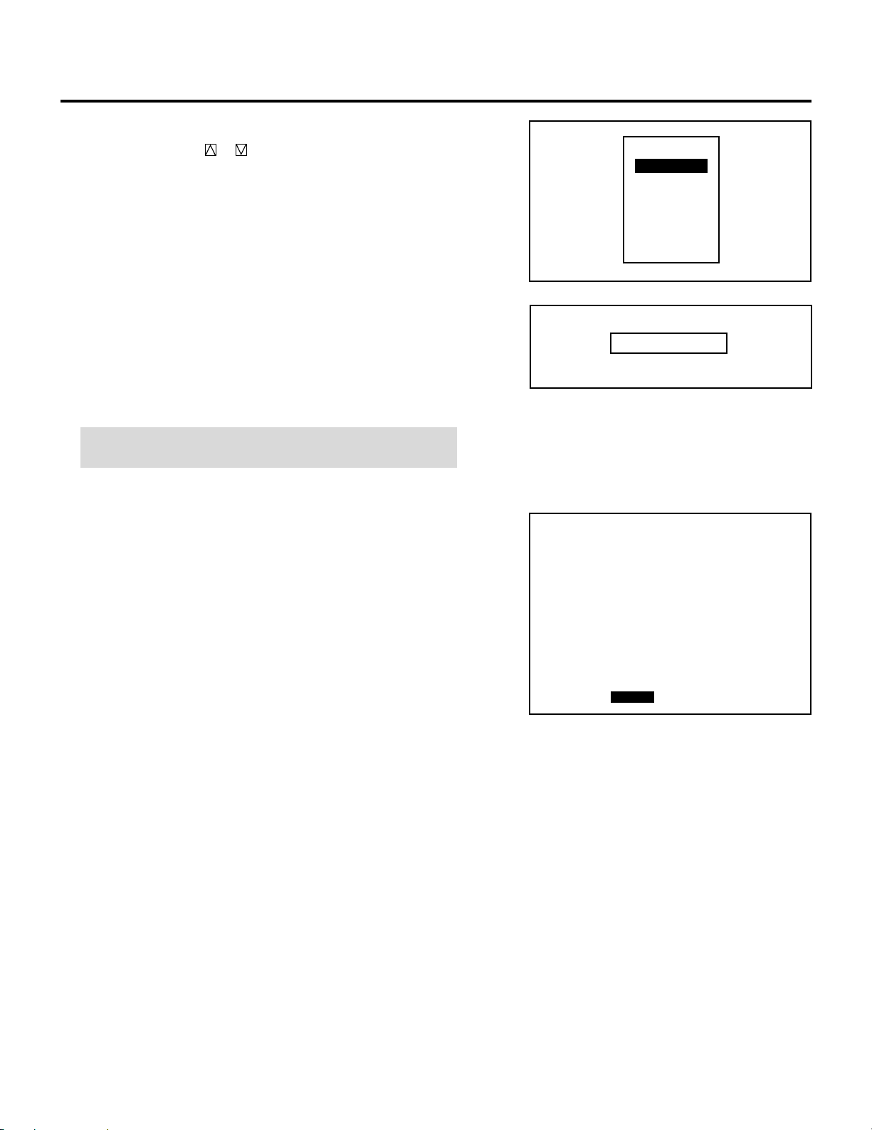
SETTING
OPTION - SEQUENCER -
P01
NO
01
02
03
04
05
06
07
08
09
10
INPUT
VIDEO
WAIT
P-OFF
TIME
00:20:00
SMTWTFS
OOOOOOO
OOOOOOO
START EDIT
m Selecting “WAIT”
1) Use the CURSOR or button to select “WAIT” and press
ENTER.
• The “TIME” input screen will be displayed.
2) Type the waiting time using the INPUT buttons and press
ENTER.
• Type the time in hours, minutes, and seconds.
• If you have made an error in the input of numbers, press the
END button to return to the Program menu on step 1), then
start again.
NOTE: The waiting time cannot exceed 23 hours, 59 minutes,
and 59 seconds.
INPUT
WAIT
GOTO
LOOP
P-ON
P-OFF
INSERT
DELETE
TIME __:__:__
Example:
When the following program is set, the display as shown on the
right will appear:
First line:Select VIDEO, then type “99:99:99” in the TIME input
screen, then select “DAILY” in the WEEK SELECT menu for
“INPUT”.
Second line:Select type “00:20:00” in the TIME input screen for
“WAIT”.
Third line:Type “99:99:99”, then select “DAILY” for “P-OFF”.
When this program starts, the input signal will change to VIDEO
immediately. Then, the current condition will be retained for 20
minutes.
Finally, the power will be turned off.
The “WAIT” function is used to execute the command immediately.
112

m Selecting “GOTO”
1) Use the CURSOR or button to select “GOTO” and press
ENTER.
• The “GOTO” input screen will be displayed.
2) Enter the scan number line to which you want to jump to
using the INPUT button and press ENTER.
• If you have made an error, press END to return to the
Program menu, then start again.
• The “SEQUENCER” screen will be restored to its last
setting.
SETTING
INPUT
WAIT
GOTO
LOOP
P-ON
P-OFF
INSERT
DELETE
GOTO __
m Selecting “LOOP”
1) Use the CURSOR or button to select “LOOP” and press
ENTER.
• The “LOOP/COUNT” input screen will be displayed.
2) Enter the number of the destination line (LOOP) and the
number of the loop times (COUNT) in this order using the
INPUT button and press ENTER.
• If you have made an error, press END to return to the
Program menu, then start again.
• The “SEQUENCER” screen will be restored to its last
setting.
INPUT
WAIT
GOTO
LOOP
P-ON
P-OFF
INSERT
DELETE
LOOP __ COUNT __
113

SETTING
m Selecting “P-ON”
1) Use the CURSOR or button to select “P-ON” and press
ENTER.
• The POWER ON input screen will be displayed.
2) Enter the POWER ON TIME you wish to turn on the projector using INPUT buttons and press ENTER.
• Type the time in hours (24 hours), minutes and seconds.
• If you made an error, press END to return to the Program
menu, then start again.
NOTE 1: Typing 99:99:99 in the time input menu will execute
the program immediately.
NOTE 2: The P-ON command is available only when the
projector is off (in the standby condition).
The P-ON command is ignored if set in the first line. In this
case, the program will start its execution from the second line.
INPUT
WAIT
GOTO
LOOP
P-ON
P-OFF
INSERT
DELETE
TIME __:__:__
m Selecting “P-OFF”
1) Use the CURSOR or button to select “P-OFF” and press
ENTER.
• The POWER OFF input screen will be displayed.
2) Enter the POWER OFF TIME you wish to turn on the
projector using INPUT buttons and press ENTER.
• Type the time in hours (24 hours), minutes and seconds.
• If you made an error, press END to return to the Program
menu, then start again.
NOTE: Typing 99:99:99 in the time input menu will execute the
program immediately. (See the example in the “WAIT” section
on page 108)
INPUT
WAIT
GOTO
LOOP
P-ON
P-OFF
INSERT
DELETE
TIME __:__:__
114

m Selecting “INSERT”
OPTION - SEQUENCER -
P01
NO
01
02
03
04
05
06
07
08
09
10
INPUT
M-10
M-02
M-01
WAIT
M-01
WAIT
LOOP
M-02
P-OFF
P-ON
S-01
S-02
S-02
S-01
03 COUNT 05
S-02
TIME
12:00:00
14:00:00
00:10:00
00:20:00
15:50:00
18:00:00
09:00:00
START EDIT
SMTWTFS
XOOOOOX
XOOOOOX
XOOOOOX
XOOOOOX
XOOOOOX
XOOOOOX
XOOOOOX
OPTION - SEQUENCER -
P01
NO
01
02
03
04
05
06
07
08
09
10
INPUT
M-10
M-02
M-01
WAIT
M-01
WAIT
LOOP
M-02
P-OFF
P-ON
S-01
S-02
S-02
S-01
03 COUNT 05
S-02
TIME
12:00:00
14:00:00
00:10:00
00:20:00
15:50:00
18:00:00
09:00:00
START EDIT
SMTWTFS
XOOOOOX
XOOOOOX
XOOOOOX
XOOOOOX
XOOOOOX
XOOOOOX
XOOOOOX
1) Use the CURSOR or button to select “INSERT” and
press ENTER.
2) Use the CURSOR or button to select where you wish to
insert a vacant line and press ENTER.
• The highlighted line will be switched to a vacant line and
the original line(s) will be moved down.
SETTING
INPUT
WAIT
GOTO
LOOP
P-ON
P-OFF
INSERT
DELETE
m Selecting “DELETE”
1) Use the CURSOR or button to select “DELETE” and
press ENTER.
2) Use the CURSOR or button to select the line you wish
to delete and press ENTER.
• The selected line will be deleted and the following line(s)
will be moved up.
INPUT
WAIT
GOTO
LOOP
P-ON
P-OFF
INSERT
DELETE
115

SETTING
OPTION - SEQUENCER -
P01
NO
01
02
03
04
05
06
07
08
09
10
INPUT
M-10
M-02
M-01
WAIT
M-01
WAIT
LOOP
M-02
P-OFF
P-ON
S-01
S-02
S-02
S-01
03 COUNT 05
S-02
TIME
12:00:00
14:00:00
00:10:00
00:20:00
15:50:00
18:00:00
09:00:00
SMTWTFS
XOOOOOX
XOOOOOX
XOOOOOX
XOOOOOX
XOOOOOX
XOOOOOX
XOOOOOX
START EDIT
7 Pressing the END button will exit the “EDIT” mode.
Select “START” and press ENTER to execute the program.
•The “*EXECUTING NO. XX*” will appear during program
execution. When the program is finished, the “*SEQUENCER
END*” message will appear for about five seconds.
NOTE: To cancel the program, hold down the CTL button then
press END. The “*SEQUENCER MANUAL END*” will appear for
about five seconds.
8 To end this mode, press the END button.
• Whenever the END button is pressed, the menus will sequence
in this order:
“SEQUENCER” screen (No highlighted line) → “ADJUST”
menu → Source screen
• If the “RETURN USER MODE?” menu appears, use the
CURSOR or button to select either “YES” or “NO” and
then press ENTER. This will exit the ADJUST mode.
RETURN USER MODE?
YES NO
Items to select
• YES ......... When you try to enter the ADJUST mode the next
time, you will need to re-enter your passcode.
• N O ........... When you try to enter the ADJUST mode the next
time, you will not need to re-enter your passcode.
116

Address Setting
Each projector needs its own unique address in the case of a serial
connection of projectors. Up to 64 addresses can be set.
Proceed as follows:
1 Press the ADJUST button to display the “ADJUST” menu.
• The projector may ask you to enter your passcode.
See page 61 for the explanation of the PASSCODE.
SETTING
2 Use the CURSOR or button to highlight the “8/OPTION”
line. Press ENTER to display the “OPTION” menu. You can also
select the “OPTION” menu directly by pressing the INPUT “8”
button.
3 Use the CURSOR or button to highlight the “4/PJ AD-
DRESS” line. Press ENTER to display the “ADDRESS” screen.
You can also select the “ADDRESS” menu directly by pressing
the INPUT “4” button or the ADDRESS button on the full
function remote control.
– ADJUST –
1 / SIGNAL ENTRY
2 / FOCUS
3 / ALIGNMENT
4 / CONVERGENCE
5 / KELVIN
6 / R,G,B GAIN
7 / PASSCODE
8 / OPTION
9 / REF.ADJUST
– OPTION –
1 / SETTING MODE
2 / MENU MODE
3 / SEQUENCER
4 / PJ ADDRESS
5 / VERSION
6 / HOUR METER
7 / DEFAULT DATA
4 Enter the address number using the INPUT button and press
ENTER.
• If you have made a mistake, press END to return to the “OPTION” menu, then start again.
NOTE: Enter the address number “01” when only one projector
is used.
OPTION
-PJ ADDRESS-
01 (01-64)
117

SETTING
5 To complete, press the END button.
• Whenever the END button is pressed, the menus will sequence
in this order:
“OPTION” menu → “ADJUST” menu → Source screen
• If the “RETURN USER MODE?” menu appears, use the
CURSOR or button to select either “YES” or “NO” and
press ENTER. This will exit the ADJUST mode.
Items to select
• YES ......... When you try to enter the ADJUST mode the next
time, you will need to re-enter your passcode.
• N O ........... When you try to enter the ADJUST mode the next
time, you will not need to re-enter your passcode.
RETURN USER MODE?
YES NO
118

m Addressing the Remote Control Unit
When changing the projector address, ensure that the projector
address respond to the remote control address, otherwise you cannot
operate the projector using the remote control.
To specify the remote control address, proceed as follows:
1) Press and hold the CTL button then press the ADDRESS button
to access the RC UNIT address mode.
• The current remote control address is displayed on the remote
control address screen. (When the current remote control
address is configured at "00", the remote control address screen
will not be displayed.
• This screen will disappear in 30 seconds.
NOTE: When the remote control is used with the Switcher in
wired application, a window shown on the right will not be
displayed. However, the remote control address can be
changed.
2) Use INPUT buttons to enter a new two-digit number and press
ENTER.
• The new remote control address is displayed on the screen.
When the new remote control address is configured at "00", the
display will not be changed. However, its address has been
changed by pressing ENTER.
• The number you can specify ranges from 00 to 64.
SETTING
ADDRESS
RC UNIT
When the remote control address is configured at
"00", the above screen will not be displayed.
∗∗
To stop the address changing, press END.
See the projector address number on the screen.
NOTE:
• The buttons other than the above mentioned button and the
OFF button are not available during specifying the remote
control address.
• If no key input is made within 30 seconds, the remote control
automatically exits the RC UNIT address mode.
Address common to all the projectors
When specifying the remote control address as “00”, you can
operate the projector using the remote control, regardless of the
projector addresses.
If the remote control loses power, the remote control address
becomes “00”. In this case the on-screen shown on the right
above is not displayed on the screen.
119

SETTING
Projector Version Number
This function lets you know the version for hardware and software
used in the projector.
To view the Version number, proceed as follows:
1 Press the ADJUST button to display the “ADJUST” menu.
• The projector may ask you to enter your passcode.
See page 61 for the explanation of the PASSCODE.
2 Use the CURSOR or button to highlight the “8/OPTION”
line. Press ENTER to display the “OPTION” menu. You can also
select the “OPTION” menu directly by pressing the INPUT “8”
button.
3 Use the CURSOR or button to highlight the “5/VERSION”
line. Press ENTER to display the “VERSION NUMBER” menu.
You can also select the “VERSION NUMBER” menu directly by
pressing the INPUT “5” button.
• You will know what version number your applications software
and the projector are.
• The “SWITCHER” item is displayed only when the connect
condition is set to the SW 1 or 2 LEVEL.
– ADJUST –
1 / SIGNAL ENTRY
2 / FOCUS
3 / ALIGNMENT
4 / CONVERGENCE
5 / KELVIN
6 / R,G,B GAIN
7 / PASSCODE
8 / OPTION
9 / REF.ADJUST
– OPTION –
1 / SETTING MODE
2 / MENU MODE
3 / SEQUENCER
4 / PJ ADDRESS
5 / VERSION
6 / HOUR METER
7 / DEFAULT DATA
OPTION
- VERSION NUMBER -
HARDWARE VERSION
SOFTWARE VERSION
BIOS
APPLICATION
DATA
SUB-CPU
D-CONV
SWITCHER
1.00
1.00
1.00
1.00
1.00
1.00
3.00
4 To exit this menu, press END.
• Whenever the END button is pressed, the menus will sequence
in this order:
“OPTION” menu → “ADJUST” menu →Source screen
• If the “RETURN USER MODE?” menu appears, use the
CURSOR or button to select either “YES” or “NO” and
press ENTER. This will exit the ADJUST mode.
Items to select
• YES ......... When you try to enter the ADJUST mode the next
time, you will need to re-enter your passcode.
• N O ........... When you try to enter the ADJUST mode the next
time, you will not need to re-enter your passcode.
RETURN USER MODE?
YES NO
120

Checking and Setting the Running Time
The projector will give you the amount of operating time.
Proceed as follows:
1 Press the ADJUST button to display the “ADJUST” menu.
• The projector may ask you to enter your passcode.
See page 61 for the explanation of the PASSCODE.
2 Use the CURSOR or button to highlight the “8/OPTION”
line. Press ENTER to display the “OPTION” menu. You can also
select the “HOUR METER” screen directly by pressing the
INPUT “8” button.
3 Use the CURSOR or button to highlight the “6/HOUR
METER” line. Press ENTER to display the “HOUR METER”
screen. You can also select the “HOUR METER” screen directly
by pressing the INPUT “6” button.
Items to select
• PJ RUNNING TIME
The amount of operating time of the projector.
• CRT RUNNING TIME
The amount of operating time of CRT.
• USER PJ RUNNING TIME
The amount of operating time of the projector. User resetable.
SETTING
– ADJUST –
1 / SIGNAL ENTRY
2 / FOCUS
3 / ALIGNMENT
4 / CONVERGENCE
5 / KELVIN
6 / R,G,B GAIN
7 / PASSCODE
8 / OPTION
9 / REF.ADJUST
– OPTION –
1 / SETTING MODE
2 / MENU MODE
3 / SEQUENCER
4 / PJ ADDRESS
5 / VERSION
6 / HOUR METER
7 / DEFAULT DATA
How to reset the user projector or CRT running time:
1) Use the CURSOR buttons to select the item and then press
ENTER.
• The “USER PJ RUNNING TIME RESET?” or “USER
CRT RUNNING TIME RESET?” menu is displayed.
2) Use the CURSOR or button to select either “YES” or
“NO” and then press ENTER.
Items to select
• YES ......... The time will be reset
• NO ........... The time will not be reset
• The display will be returned to the “HOUR METER” screen.
HOUR METER
PJ RUNNING TIME
∗∗∗∗ ∗∗
CRT RUNNING TIME
R
∗∗∗∗
G
∗∗∗∗
B
∗∗∗∗
USER PJ RUNNING TIME
∗∗∗∗
USER PJ RUNNING TIME RESET?
HM
H
∗∗
H
∗∗
H
∗∗
H
∗∗
YES NO
M
M
M
M
121
 Loading...