

Page 1

Xen Alpha™
Xen Alpha™
Xen Alpha™Xen Alpha™
I
NSTALLATION
NEC Australia Pty Ltd
A6-506000-642-01
Release 1.0
April 2000
M
ANUAL
Page 2

This page is intentionally blank.
Page ii Features and Specifications Manual
A6-506000-642-01
Page 3

Table of Contents
Xen Alpha Release 1.0
Chapter 1
Chapter 1
Chapter 1Chapter 1
System Overview
Section 1 . . . . . . . . . . . . . . . . . . . . . . . . . 3
Your System . . . . . . . . . . . . . . . . . . . . . . . 3
Section 2 . . . . . . . . . . . . . . . . . . . . . . . . . 5
Regulatory Information . . . . . . . . . . . . . . . 5
Electromagnetic Interference (EMI) . . . . . 5
Battery Disposal . . . . . . . . . . . . . . . . . . . . 5
Incidence of Harm . . . . . . . . . . . . . . . . . . . 5
Hearing Aid Compatibility . . . . . . . . . . . . . 5
Service Requirements . . . . . . . . . . . . . . . . 5
Compliance Information . . . . . . . . . . . . . . 5
Section 3 . . . . . . . . . . . . . . . . . . . . . . . . . 6
Equipment . . . . . . . . . . . . . . . . . . . . . . . . . 6
Section 4 . . . . . . . . . . . . . . . . . . . . . . . . . 9
System Capa c it i e s . . . . . . . . . . . . . . . . . . 9
Section 5 . . . . . . . . . . . . . . . . . . . . . . . . 10
System Bloc k D ia g ram . . . . . . . . . . . . . . 10
Section 6 . . . . . . . . . . . . . . . . . . . . . . . . 11
Cabling Requirements & Specifications . 11
Section 13 . . . . . . . . . . . . . . . . . . . . . . . 16
External Equipment Connection . . . . . . . 16
Section 14 . . . . . . . . . . . . . . . . . . . . . . . 17
Battery Backup . . . . . . . . . . . . . . . . . . . . 17
System Backup . . . . . . . . . . . . . . . . . . . . 17
Memory Backup . . . . . . . . . . . . . . . . . . . 17
Section 15 . . . . . . . . . . . . . . . . . . . . . . . 18
Visual & Audible Indications . . . . . . . . . . 18
Tone Patterns Table . . . . . . . . . . . . . . . . 18
Multiline Terminal Flash Patterns Table . 21
DSS/BLF LED Indications Table . . . . . . 22
Chapter 2
Chapter 2
Chapter 2Chapter 2
KSU Installation
Section 1 . . . . . . . . . . . . . . . . . . . . . . . . 23
General Information . . . . . . . . . . . . . . . . 23
Section 2 . . . . . . . . . . . . . . . . . . . . . . . . 23
Site Preparation . . . . . . . . . . . . . . . . . . . 23
Precautionary Informati on . . . . . . . . . . . 23
Site Selection Conditions . . . . . . . . . . . . 24
Multiline Telephone Installation Site . . . . 24
Section 7 . . . . . . . . . . . . . . . . . . . . . . . . 12
Power Requirements . . . . . . . . . . . . . . . . 12
Power Supply Inp u t s . . . . . . . . . . . . . . . . 12
Power Supply Consumptio n . . . . . . . . . . 12
Section 8 . . . . . . . . . . . . . . . . . . . . . . . . 13
Environmental Conditions . . . . . . . . . . . . 13
Section 10 . . . . . . . . . . . . . . . . . . . . . . . 14
Outside Line Ty p e . . . . . . . . . . . . . . . . . . 14
Section 11 . . . . . . . . . . . . . . . . . . . . . . . 14
Network & Control . . . . . . . . . . . . . . . . . . 14
Transmission, Network & Control
Specifications . . . . . . . . . . . . . . . . . . . . 14
Section 12 . . . . . . . . . . . . . . . . . . . . . . . 15
Dialling Specifications . . . . . . . . . . . . . . . 15
Dial Pulse Address Signaling . . . . . . . . . 15
Dual-Tone Multifrequency (DTMF)
Address Signalin g . . . . . . . . . . . . . . . . 15
Section 3 . . . . . . . . . . . . . . . . . . . . . . . . 25
Installing the Key Service Unit (KSU) . . . 25
Installation Precautions . . . . . . . . . . . . . 25
The Key Service Unit . . . . . . . . . . . . . . . 25
Removing the KSU Cover . . . . . . . . . . . 26
Wall Mounting the KSU . . . . . . . . . . . . . 27
Installing or Replacing the Internal
Backup Batteries . . . . . . . . . . . . . . . . . 28
Connecting the B614-B13 KSU . . . . . . . 32
External ROM Card . . . . . . . . . . . . . . . . 37
Features and Specifications Manual Page 1
A6-506000-642-02
Page 4

Section 5 . . . . . . . . . . . . . . . . . . . . . . . . 39
Installing an Electronic Telephone
Unit ETU . . . . . . . . . . . . . . . . . . . . . . . . 39
General Information . . . . . . . . . . . . . . . . 39
Interface ETUs . . . . . . . . . . . . . . . . . . . . 40
Optional ETUs . . . . . . . . . . . . . . . . . . . . . 44
Door Phones . . . . . . . . . . . . . . . . . . . . . . 48
Door Lock Rele a se . . . . . . . . . . . . . . . . . 49
TRF-B13 ETU . . . . . . . . . . . . . . . . . . . . . 49
Trunk Transfer Speech Volume
Adjustment . . . . . . . . . . . . . . . . . . . . . . 49
Power Failure Ba c kup . . . . . . . . . . . . . . . 51
Section 3 . . . . . . . . . . . . . . . . . . . . . . . . 67
Connection A Multiline Terminal To
The System . . . . . . . . . . . . . . . . . . . . . 67
Section 4 . . . . . . . . . . . . . . . . . . . . . . . . 68
Adjusting The LCD . . . . . . . . . . . . . . . . . 68
Section 5 . . . . . . . . . . . . . . . . . . . . . . . . 68
Installing Line Cards & Plastic Panels . . 68
Line Card and Plastic Panel Installati on . 68
Plastic Panel Removal . . . . . . . . . . . . . . 69
Section 6 . . . . . . . . . . . . . . . . . . . . . . . . 70
Removing Softkeys . . . . . . . . . . . . . . . . . 70
Section 6 . . . . . . . . . . . . . . . . . . . . . . . . 52
Cable Connections . . . . . . . . . . . . . . . . . 52
General Information . . . . . . . . . . . . . . . . 52
Wiring to the KSU . . . . . . . . . . . . . . . . . . 54
Outside Lines . . . . . . . . . . . . . . . . . . . . . 54
Chapter 3
Chapter 3
Chapter 3Chapter 3
Installing DTB-Type
Multiline Terminals
Section 1 . . . . . . . . . . . . . . . . . . . . . . . . 59
General Information . . . . . . . . . . . . . . . . 59
Section 2 . . . . . . . . . . . . . . . . . . . . . . . . 59
Multiline Terminals . . . . . . . . . . . . . . . . . 59
DTB-16-1A (W H ) /( B K ) T E L . . . . . . . . . . . 59
DTB-16D-1A (W H)/(BK) TEL . . . . . . . . . 60
Section 3 . . . . . . . . . . . . . . . . . . . . . . . . 61
Wall Mounting . . . . . . . . . . . . . . . . . . . . . 61
Wall Mounting Template . . . . . . . . . . . . . 63
Section 7 . . . . . . . . . . . . . . . . . . . . . . . . 70
Adjusting The Height Of The
Multiline Terminal . . . . . . . . . . . . . . . . 70
Section 8 . . . . . . . . . . . . . . . . . . . . . . . . 72
Wall Mounting . . . . . . . . . . . . . . . . . . . . . 72
Section 9 . . . . . . . . . . . . . . . . . . . . . . . . 78
Installing Optional Adapters . . . . . . . . . . 78
Preparing Multiline Terminal for
Adapter Installation . . . . . . . . . . . . . . . 78
ACA-UA Unit (AC Adapter) . . . . . . . . . . . 80
ADA-UA Unit (Ancillary Device Adapter) 81
APR-UA Unit (Analogue Port Ringer) . . . 86
CTA-UA Unit (Computer Telephony
Application) . . . . . . . . . . . . . . . . . . . . . 89
HFU-UA (WH) Unit (Handsfree Unit) . . . 91
Chapter 5
Chapter 5
Chapter 5Chapter 5
Installing DTW-Type
Multiline Terminals
Section 1 . . . . . . . . . . . . . . . . . . . . . . . . 93
Chapter 4
Chapter 4
Chapter 4Chapter 4
Installing DTU-Type
Multiline Terminals
Section 1 . . . . . . . . . . . . . . . . . . . . . . . . 65
General Information . . . . . . . . . . . . . . . . 65
Section 2 . . . . . . . . . . . . . . . . . . . . . . . . 65
Multiline Terminals . . . . . . . . . . . . . . . . . 65
DTU-8-1A (WH) TEL . . . . . . . . . . . . . . . . 65
DTU-8D-1A (WH) TEL . . . . . . . . . . . . . . 65
DTU-16D-1A (WH) TEL . . . . . . . . . . . . . 66
DTU-32D-1A (WH) TEL . . . . . . . . . . . . . 66
Page 2 Features and Specifications Manual
General Information . . . . . . . . . . . . . . . . 93
Section 2 . . . . . . . . . . . . . . . . . . . . . . . . 93
ETW-Type Multiline Terminals . . . . . . . . 93
Section 3 . . . . . . . . . . . . . . . . . . . . . . . . 94
Connecting an ETW-Type Multiline
Terminal . . . . . . . . . . . . . . . . . . . . . . . . 94
Terminal Update . . . . . . . . . . . . . . . . . . . 94
Attach a Multiline Terminal to the System 94
A6-506000-642-02
Page 5

Chapter 6
Chapter 6
Chapter 6Chapter 6
Installing Optional
Terminal Equipment
Section 1 . . . . . . . . . . . . . . . . . . . . . . . . 95
SLT(1)-U13 ADP (Single Line Telephone) 95
Chapter 7
Chapter 7
Chapter 7Chapter 7
System Programming
Section 1 . . . . . . . . . . . . . . . . . . . . . . . . 97
Features and Specifications Manual Page 3
A6-506000-642-02
Page 6

This page is intentionally blank.
Page 4 Features and Specifications Manual
A6-506000-642-02
Page 7

List of Figures
Xen Alpha Release 1.0
Chapter 1System Overview
System Configuration Sample . . . . . . . . . . . . . . . . . . . . . . . . . . . . . . . . . . . . . . . . . . . . . . .4
NEC Xen Alpha System Block Diagram . . . . . . . . . . . . . . . . . . . . . . . . . . . . . . . . . . . . . .10
Connecting the ESI to the Multiline Telephone Using
Twisted 2-Pair Cable . . . . . . . . . . . . . . . . . . . . . . . . . . . . . . . . . . . . . . . . . . . . . . . . . . . . .11
Chapter 2KSU Installation
Front View of a KSU . . . . . . . . . . . . . . . . . . . . . . . . . . . . . . . . . . . . . . . . . . . . . . . . . . . . .25
How to Remove the KSU Cover . . . . . . . . . . . . . . . . . . . . . . . . . . . . . . . . . . . . . . . . . . . .26
Attaching the Wall Mounting Bracket for the KSU to the Wall . . . . . . . . . . . . . . . . . . . . . .27
Attaching the KSU to the Wall Mount Template . . . . . . . . . . . . . . . . . . . . . . . . . . . . . . . .27
Securing the KSU to the Wall Mount Template . . . . . . . . . . . . . . . . . . . . . . . . . . . . . . . . .28
Inserting a New Battery in the KSU Unit . . . . . . . . . . . . . . . . . . . . . . . . . . . . . . . . . . . . . .28
Attaching the Battery Connectors . . . . . . . . . . . . . . . . . . . . . . . . . . . . . . . . . . . . . . . . . . .29
. . . . . . . . . . . . . . . . . . . . . . . . . . . . . . . . . . . . . . . . . . . . . . . . . . . . . . . . . . . . . . . . . . . . . .30
. . . . . . . . . . . . . . . . . . . . . . . . . . . . . . . . . . . . . . . . . . . . . . . . . . . . . . . . . . . . . . . . . . . . . .30
. . . . . . . . . . . . . . . . . . . . . . . . . . . . . . . . . . . . . . . . . . . . . . . . . . . . . . . . . . . . . . . . . . . . . .30
Mounting the External Battery Cabi net . . . . . . . . . . . . . . . . . . . . . . . . . . . . . . . . . . . . . . .31
Connecting External Batteries . . . . . . . . . . . . . . . . . . . . . . . . . . . . . . . . . . . . . . . . . . . . . .31
KSU Grounding . . . . . . . . . . . . . . . . . . . . . . . . . . . . . . . . . . . . . . . . . . . . . . . . . . . . . . . . .32
KSU Switch Settings . . . . . . . . . . . . . . . . . . . . . . . . . . . . . . . . . . . . . . . . . . . . . . . . . . . . .33
Telephone Connection . . . . . . . . . . . . . . . . . . . . . . . . . . . . . . . . . . . . . . . . . . . . . . . . . . . .34
Exchange Line Connection . . . . . . . . . . . . . . . . . . . . . . . . . . . . . . . . . . . . . . . . . . . . . . . .34
Power Fail Telephone and Fax Connection . . . . . . . . . . . . . . . . . . . . . . . . . . . . . . . . . . . .35
External Ringer Connection . . . . . . . . . . . . . . . . . . . . . . . . . . . . . . . . . . . . . . . . . . . . . . . .35
External Paging Connection . . . . . . . . . . . . . . . . . . . . . . . . . . . . . . . . . . . . . . . . . . . . . . .36
MOH/BGM Source Connection . . . . . . . . . . . . . . . . . . . . . . . . . . . . . . . . . . . . . . . . . . . . .37
External ROM Card . . . . . . . . . . . . . . . . . . . . . . . . . . . . . . . . . . . . . . . . . . . . . . . . . . . . . .37
Inserting the External ROM Card . . . . . . . . . . . . . . . . . . . . . . . . . . . . . . . . . . . . . . . . . . . .38
Installing a Vertically Mounted KTU . . . . . . . . . . . . . . . . . . . . . . . . . . . . . . . . . . . . . . . . . .39
ESI(8)-B13 ETU . . . . . . . . . . . . . . . . . . . . . . . . . . . . . . . . . . . . . . . . . . . . . . . . . . . . . . . . .40
SLI(2)-B13 ETU . . . . . . . . . . . . . . . . . . . . . . . . . . . . . . . . . . . . . . . . . . . . . . . . . . . . . . . . .41
COI(2)-B13 ETU . . . . . . . . . . . . . . . . . . . . . . . . . . . . . . . . . . . . . . . . . . . . . . . . . . . . . . . .42
Mounting the CID(2)-B13 Unit onto the Mainboard . . . . . . . . . . . . . . . . . . . . . . . . . . . . . .42
Mounting the CID(2)-B13 Unit onto the COI(2)-B 13 ETU . . . . . . . . . . . . . . . . . . . . . . . . .43
BRT(1)-B13 ETU . . . . . . . . . . . . . . . . . . . . . . . . . . . . . . . . . . . . . . . . . . . . . . . . . . . . . . . .44
BRT(1)-B13 ETU Connection Cable . . . . . . . . . . . . . . . . . . . . . . . . . . . . . . . . . . . . . . . . .44
PBR-B13 ETU . . . . . . . . . . . . . . . . . . . . . . . . . . . . . . . . . . . . . . . . . . . . . . . . . . . . . . . . . .45
Removing the Ground Plate . . . . . . . . . . . . . . . . . . . . . . . . . . . . . . . . . . . . . . . . . . . . . . .45
Mounting the DB-9 Plate . . . . . . . . . . . . . . . . . . . . . . . . . . . . . . . . . . . . . . . . . . . . . . . . . .45
Installation Manual
A6-506000-642-01
Table of Contents Page 1
• • •
Page 8

Connecting the DB-9 Cable . . . . . . . . . . . . . . . . . . . . . . . . . . . . . . . . . . . . . . . . . . . . . . . .46
MIF-B13 ETU . . . . . . . . . . . . . . . . . . . . . . . . . . . . . . . . . . . . . . . . . . . . . . . . . . . . . . . . . . .46
DHP-B13 ETU . . . . . . . . . . . . . . . . . . . . . . . . . . . . . . . . . . . . . . . . . . . . . . . . . . . . . . . . . .47
TRF-B13 ETU . . . . . . . . . . . . . . . . . . . . . . . . . . . . . . . . . . . . . . . . . . . . . . . . . . . . . . . . . .49
Power Failure Backup Flowchart . . . . . . . . . . . . . . . . . . . . . . . . . . . . . . . . . . . . . . . . . . . .51
Holding the Connector with the Pliers . . . . . . . . . . . . . . . . . . . . . . . . . . . . . . . . . . . . . . . .53
Attaching the Cables to the Connector . . . . . . . . . . . . . . . . . . . . . . . . . . . . . . . . . . . . . . .53
Multiline Terminal and SLT Adapter Connection . . . . . . . . . . . . . . . . . . . . . . . . . . . . . . . .54
Single Line Telephone Connection . . . . . . . . . . . . . . . . . . . . . . . . . . . . . . . . . . . . . . . . . .54
KSU Cabling Knockouts . . . . . . . . . . . . . . . . . . . . . . . . . . . . . . . . . . . . . . . . . . . . . . . . . .55
Removing the Knockout Panels in the KSU . . . . . . . . . . . . . . . . . . . . . . . . . . . . . . . . . . .55
DTB-16-1A (WH)/(BK) TEL Multiline Telephone . . . . . . . . . . . . . . . . . . . . . . . . . . . . . . . .59
Chapter 3Installing DTB-Type Multiline
Terminals
DTB-16D-1A (WH)/(BK) TEL Multiline Telephone . . . . . . . . . . . . . . . . . . . . . . . . . . . . . . .60
DTU-8-1A (WH) TEL Multiline Terminal . . . . . . . . . . . . . . . . . . . . . . . . . . . . . . . . . . . . . . .65
DTU-8D-1A (BK)/(WH) TEL Multiline Terminal . . . . . . . . . . . . . . . . . . . . . . . . . . . . . . . . .65
Chapter 4Installing DTU-Type Multiline
Terminals
DTU-16D-1A (WH) TEL Multiline Terminal . . . . . . . . . . . . . . . . . . . . . . . . . . . . . . . . . . . .66
DTU-32D-1A (WH) TEL Multiline Terminal . . . . . . . . . . . . . . . . . . . . . . . . . . . . . . . . . . . .66
Connecting a Multiline Terminal to the System . . . . . . . . . . . . . . . . . . . . . . . . . . . . . . . . .67
Leading Line Cords on a Multiline Terminal . . . . . . . . . . . . . . . . . . . . . . . . . . . . . . . . . . .67
Adjusting the LCD . . . . . . . . . . . . . . . . . . . . . . . . . . . . . . . . . . . . . . . . . . . . . . . . . . . . . . .68
Installing Line Card and Plastic Panel on a Multiline Terminal . . . . . . . . . . . . . . . . . . . . .68
Installing Plastic Panel . . . . . . . . . . . . . . . . . . . . . . . . . . . . . . . . . . . . . . . . . . . . . . . . . . . .69
Removing the Plastic Panel from the Multilin e Term inal . . . . . . . . . . . . . . . . . . . . . . . . . .69
Removing Softkeys . . . . . . . . . . . . . . . . . . . . . . . . . . . . . . . . . . . . . . . . . . . . . . . . . . . . . .70
Locating the Adjustment Tabs on the Multiline Terminal . . . . . . . . . . . . . . . . . . . . . . . . . .70
Raising the Base Plate on the Multiline Terminal . . . . . . . . . . . . . . . . . . . . . . . . . . . . . . .71
Adjusting the Line Cord Length . . . . . . . . . . . . . . . . . . . . . . . . . . . . . . . . . . . . . . . . . . . . .71
Lowering the Base Plate on the Multiline Terminal . . . . . . . . . . . . . . . . . . . . . . . . . . . . . .71
Positioning the Handset Hanger . . . . . . . . . . . . . . . . . . . . . . . . . . . . . . . . . . . . . . . . . . . .72
Removing the Knockout . . . . . . . . . . . . . . . . . . . . . . . . . . . . . . . . . . . . . . . . . . . . . . . . . . .72
Attaching the Base Plate to the Wall . . . . . . . . . . . . . . . . . . . . . . . . . . . . . . . . . . . . . . . . .73
Wall Mounting using a Modular Jack . . . . . . . . . . . . . . . . . . . . . . . . . . . . . . . . . . . . . . . . .73
Plugging in the Line Cord using a Wall Jack . . . . . . . . . . . . . . . . . . . . . . . . . . . . . . . . . . .73
Plugging in the Line Cord Using a Modular Jack . . . . . . . . . . . . . . . . . . . . . . . . . . . . . . . .74
Attaching th e Bottom Tabs of the M u lti lin e Te rminal to the Ba se C o ve r . . . . . . . . . . . . . .74
Installation Manual
A6-506000-642-01
Table of Contents Page 2
• • •
Page 9

Attaching the Top Tabs of the Multiline Terminal to the Base Plate . . . . . . . . . . . . . . . . .74
Installed Wall Mount Unit . . . . . . . . . . . . . . . . . . . . . . . . . . . . . . . . . . . . . . . . . . . . . . . . . .75
Removing the Tabs from the Adapter . . . . . . . . . . . . . . . . . . . . . . . . . . . . . . . . . . . . . . . .75
Removing the Tabs from the WMU-UA Unit . . . . . . . . . . . . . . . . . . . . . . . . . . . . . . . . . . .76
Leading the Line Cord out of the WMU-UA Unit . . . . . . . . . . . . . . . . . . . . . . . . . . . . . . . .76
Attaching the Wall Mount Unit to the Wall . . . . . . . . . . . . . . . . . . . . . . . . . . . . . . . . . . . . .77
Attaching the Multiline Terminal to the WMU-UA Unit . . . . . . . . . . . . . . . . . . . . . . . . . . . .77
Removing the Multiline Terminal from the Base Cover . . . . . . . . . . . . . . . . . . . . . . . . . . .78
Raising the Base Plate . . . . . . . . . . . . . . . . . . . . . . . . . . . . . . . . . . . . . . . . . . . . . . . . . . .78
Unlocking Tab . . . . . . . . . . . . . . . . . . . . . . . . . . . . . . . . . . . . . . . . . . . . . . . . . . . . . . . . . .79
Releasing Right Tab . . . . . . . . . . . . . . . . . . . . . . . . . . . . . . . . . . . . . . . . . . . . . . . . . . . . .79
Removing Bottom Cover . . . . . . . . . . . . . . . . . . . . . . . . . . . . . . . . . . . . . . . . . . . . . . . . . .79
Removing Base Plate Dummy End . . . . . . . . . . . . . . . . . . . . . . . . . . . . . . . . . . . . . . . . . .79
Cutting Dummy End in Half . . . . . . . . . . . . . . . . . . . . . . . . . . . . . . . . . . . . . . . . . . . . . . . .80
Installing Adapter in Connector 1 . . . . . . . . . . . . . . . . . . . . . . . . . . . . . . . . . . . . . . . . . . . .80
Installing Dummy End B . . . . . . . . . . . . . . . . . . . . . . . . . . . . . . . . . . . . . . . . . . . . . . . . . .80
ACA-UA Unit Connection . . . . . . . . . . . . . . . . . . . . . . . . . . . . . . . . . . . . . . . . . . . . . . . . . .81
Attaching the ADA-UA Unit to the Multili ne Terminal . . . . . . . . . . . . . . . . . . . . . . . . . . . . .81
Leading the Audio Cable out from the ADA-UA Unit . . . . . . . . . . . . . . . . . . . . . . . . . . . . .82
ADA-UA Unit . . . . . . . . . . . . . . . . . . . . . . . . . . . . . . . . . . . . . . . . . . . . . . . . . . . . . . . . . . .82
Attaching Cables to the ADA-UA Unit . . . . . . . . . . . . . . . . . . . . . . . . . . . . . . . . . . . . . . . .82
ADA-UA Unit Switch Settings . . . . . . . . . . . . . . . . . . . . . . . . . . . . . . . . . . . . . . . . . . . . . .84
APR-UA Unit . . . . . . . . . . . . . . . . . . . . . . . . . . . . . . . . . . . . . . . . . . . . . . . . . . . . . . . . . . .86
Attaching the Unit to the Multiline Terminal . . . . . . . . . . . . . . . . . . . . . . . . . . . . . . . . . . . .86
Leading the Telephone Cord out from the Unit . . . . . . . . . . . . . . . . . . . . . . . . . . . . . . . . .87
Closing the Base Plate Cover . . . . . . . . . . . . . . . . . . . . . . . . . . . . . . . . . . . . . . . . . . . . . .87
APR-UA Unit Switches . . . . . . . . . . . . . . . . . . . . . . . . . . . . . . . . . . . . . . . . . . . . . . . . . . .87
Connecting Cables on the APR-UA Unit . . . . . . . . . . . . . . . . . . . . . . . . . . . . . . . . . . . . . .88
Attaching a Xen Multiline Terminal to a PC . . . . . . . . . . . . . . . . . . . . . . . . . . . . . . . . . . . .89
CTA-UA Unit . . . . . . . . . . . . . . . . . . . . . . . . . . . . . . . . . . . . . . . . . . . . . . . . . . . . . . . . . . .89
Attaching the Unit to the Multiline Terminal . . . . . . . . . . . . . . . . . . . . . . . . . . . . . . . . . . . .90
Connecting the RS-232C Cable to the CTA-UA Unit on the Multiline Terminal . . . . . . . . .90
HFU-UA (WH) Unit . . . . . . . . . . . . . . . . . . . . . . . . . . . . . . . . . . . . . . . . . . . . . . . . . . . . . .91
Microphone with Mute . . . . . . . . . . . . . . . . . . . . . . . . . . . . . . . . . . . . . . . . . . . . . . . . . . . .91
Attaching a Microphone to a Multiline Terminal . . . . . . . . . . . . . . . . . . . . . . . . . . . . . . . . .91
HFU-UA (WH) Unit Switches . . . . . . . . . . . . . . . . . . . . . . . . . . . . . . . . . . . . . . . . . . . . . . .92
Chapter 5Installing DTW-Type Multiline
Terminals
Modular Terminal Connections for Multiline Terminals
& Attendant Add-on Consoles . . . . . . . . . . . . . . . . . . . . . . . . . . . . . . . . . . . . . . . . . . . . . .9 4
Connecting an ETW-Type Multiline Terminal . . . . . . . . . . . . . . . . . . . . . . . . . . . . . . . . . .94
Connecting a Single Line Telephone to the System
using an SLT(1)-U13 ADP . . . . . . . . . . . . . . . . . . . . . . . . . . . . . . . . . . . . . . . . . . . . . . . . .95
Installation Manual
A6-506000-642-01
Table of Contents Page 3
• • •
Page 10

Chapter 6Installing Optional Terminal Equipment
Connecting the SLT(1)-U13 ADP . . . . . . . . . . . . . . . . . . . . . . . . . . . . . . . . . . . . . . . . . . .96
Removing the Screws from the SLT(1)-U13 ADP . . . . . . . . . . . . . . . . . . . . . . . . . . . . . . .96
Attaching the SLT(1)-U13 ADP to the Wall . . . . . . . . . . . . . . . . . . . . . . . . . . . . . . . . . . . .96
Chapter 7System Programming
There are no figures for this chapter.
Installation Manual
A6-506000-642-01
Table of Contents Page 4
• • •
Page 11

List of Tables
Xen Alpha Release 1.0
Chapter 1System Overview
Multiline Telephone Loop Resistance and Cable Length . . . . . . . . . . . . . . . . . . . . . . . . .11
Cable Connection Between the Analogue Port Adapter and the
Single Line Telephone . . . . . . . . . . . . . . . . . . . . . . . . . . . . . . . . . . . . . . . . . . . . . . . . . . . .12
Power Consumption
Weights and Dimensions . . . . . . . . . . . . . . . . . . . . . . . . . . . . . . . . . . . . . . . . . . . . . . . . . .13
Internal and External Battery Specifications . . . . . . . . . . . . . . . . . . . . . . . . . . . . . . . . . . .17
Tone Patterns . . . . . . . . . . . . . . . . . . . . . . . . . . . . . . . . . . . . . . . . . . . . . . . . . . . . . . . . . .18
Multiline LED Patterns . . . . . . . . . . . . . . . . . . . . . . . . . . . . . . . . . . . . . . . . . . . . . . . . . . . .21
DSS/BLF LED Indications . . . . . . . . . . . . . . . . . . . . . . . . . . . . . . . . . . . . . . . . . . . . . . . . .22
Chapter 2KSU Installation
. . . . . . . . . . . . . . . . . . . . . . . . . . . . . . . . . . . . . . . . . . . . . . . . . . . . . . 12
KSU Switches and Connections . . . . . . . . . . . . . . . . . . . . . . . . . . . . . . . . . . . . . . . . . . . .33
DPH-B13 ETU Switch Settings . . . . . . . . . . . . . . . . . . . . . . . . . . . . . . . . . . . . . . . . . . . . .48
TRF-B13 ETU Switch Settings . . . . . . . . . . . . . . . . . . . . . . . . . . . . . . . . . . . . . . . . . . . . .50
CO/PBX Line Loss Compensation . . . . . . . . . . . . . . . . . . . . . . . . . . . . . . . . . . . . . . . . . . .50
Chapter 3Installing DTB-Type Multiline
Terminals
There are no tables to list for this chapter.
Chapter 4Installing DTU-Type Multiline
Terminals
ADA-UA Cable Connections . . . . . . . . . . . . . . . . . . . . . . . . . . . . . . . . . . . . . . . . . . . . . . .83
ADA-UA Unit Switch Settings
HFU-UA (WH) Unit Switch Settings . . . . . . . . . . . . . . . . . . . . . . . . . . . . . . . . . . . . . . . . . .92
. . . . . . . . . . . . . . . . . . . . . . . . . . . . . . . . . . . . . . . . . . . . . . 85
Installation Manual
A6-506000-642-01
Table of Contents Page 1
• • •
Page 12

Chapter 5Installing DTW-Type Multiline
Terminals
There are no tables to list for this chapter.
Chapter 6Installing Optional Terminal Equipment
Programming Functions . . . . . . . . . . . . . . . . . . . . . . . . . . . . . . . . . . . . . . . . . . . . . . . . . . 97
Chapter 7System Programming
There are no tables to list for this chapter.
Page 2 Table of Contents
Installation Manual
• • •
A6-506000-642-01
Page 13

C
HAPTER
1
System Overview
Xen Alpha Release 1.0
S
ECTION
Y
OUR
1
S
YSTEM Your NEC Xen Alpha provides you a complete communications system to enhance your
business. The Xen Alpha telephone provides for a maximum of six lines and sixteen
telephones. This system is easy to install, operate, and maintain and provides you the
benefits and many of the features of a larger key telephone system.
Your system is easy to install, allowing you to have your system up and running in a very
short time using the system defaults. Should you need to customize your system, an easyto-use Windows 95/98 PC based software is provided. You can also make changes using a
telephone.
Your system provides batt e ry backup in case of a power outages. System pr ogramming and
speed dialling is retained for a minimum of 3 months, if your CPU battery is fully charged.
The battery located in key service unit (KSU) allows your telephones to continue operating
for approximately 30 minutes in the event of a power outage.
Xen Alpha is a feature-rich system that provides telephone functions and support many
advanced features such as:
! Computer Telephony Integration (CTI)
! Call Forwar d E x te r n al
! ISDN-BRI Voice Trunks
! Caller ID
! Integrated Digital Voice Mail
The Xen Alpha system offers a variety of Multiline Terminals. These Multiline Terminals are
available in 8-button, 16-button and 32-button capacities and are offered as display and
non-display models. A budget and premium range of Multiline Terminals is available.
A customer with existing ETW terminals can easily connect them to the Xen Alpha system,
providing inexpensive migration from the NEC Ranger NDK/DK systems. Most Xen Alpha
system features are available with the ETW-type Multiline Terminals.
ETW-type terminals are not available in New Zealand.
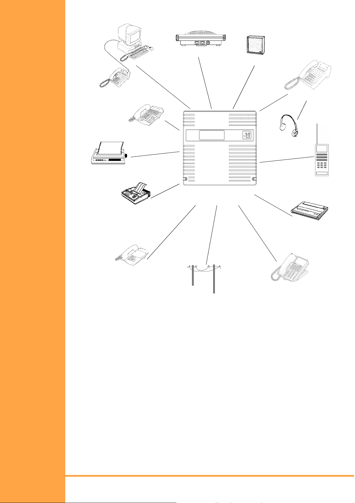
The Xen Alpha systems support a wide range of additional equi pment that can be c onnected
to the system to accommodate individual customer needs.
Equipment such as Single Line Telephones, external speakers, fa csimil e machi nes, exte rnal
microphones, and headsets can be connected. The diagram in Figure 1-1:: System
Configuration Sample, Pg 4 shows a Xen Alpha system with standard and optional
equipment (some locally provided).
Installation Manual
A6-506000-642-01
System Overview Page 3
• • •
Page 14
.
External
Speakerphone
External
Speaker
Computer Telephony Integration
Multiline Terminal
(ETW-type)
tation Message Detail
Recording (SMDR )
Facsimile
NEC XEN A
LPHA
Multiline Terminal
Headset
(DTU-type)
Cordless Singe
Telephone
Answering
Machine
Line
Single Line Telephone
CO/PBX/Centrex
Basic Rate ISDN
Figure 1-1: System Configuration Sample
Multiline Terminal
(DTB Type)
Page 4 System Overview
Installation Manual
• • •
A6-506000-642-01
Page 15

S
ECTION
R
EGULATORY
I
NFORMATION
2
Electromagnetic Interf erence (EMI)
Warning: This is a Class A product. In a domestic environment this product may cause
radio interference in which case the user may be required to take adequate
measures.
Battery Disposal
The NEC Xen Alpha system includes the following batteries. When disposing of these
batteries, KSUs and/or KTUs, you must comply with the rules and regulations of your state
regarding proper disposal procedures.
Unit Name Type of Battery Quantity
B614-B13 KSU Lead Acid
Lithium
IMPORTANT SAFEGUARDS OF BATTERY DISPOSAL
2
1
The product that you have purchased contains a rechargeable battery. The battery must be
disposed of properly.
Incidence of Harm
If the System is malfunctioning, it may also be causing harm to the telephone network. The
Telephone system should be disconnected until the source of the problem can be
determined and until repair has been made. If this is not done, the Network Provider may
temporarily disconnect the service.
Hearing Aid Compatibility
The NEC Multiline Terminals that are provided for this system are hearing aid compatible.
The manufacturer of Single Line Telephones for use with the system must provide notice of
hearing aid compatibility to comply with ACA Technical Standards.
Service Requirements
Installation Manual
A6-506000-642-01
In the event of equipment malfunction, all repairs should be performed by an authorised
dealer of NEC Australia Pty Ltd or by NEC Australia Pty Ltd. It is the responsibility of users
requiring service to report the need for service to one of NEC Australia Pty Ltd authorised
agents or to NEC Australia Pty Ltd.
Compliance Information
This equipment has been tested to comply with all relevant ACA Technical Standards.
System Overview Page 5
• • •
Page 16

S
ECTION
E
QUIPMENT The following table lists the equipment that is available with your system. The KSU
3
Quantities column indicates the maximum number of pieces of equipment that can be
installed for each system.
Equipment Name Description Quantity
Key Service Units, Power Supply Units, and Adapters
The Basic Key Service Unit (KSU) for the InfoSet system
provides service for outside lines and interconnection of the
telephones. The basi c KSU supports up to two trunk lines and
B614-B13 KSU
six telephones.
The B614-B13 KSU has a dedicated ESI slot, SLI slot, DPH
slot, PBR slot. TRF slot, VRS/VMS slot, 2 x COI/BRT slots
and MIF slot.
Common Electronic Telephone Units
1 per system
MIF-B13 ETU
BRT(1)-B13 ETU
CID-B13 UNIT
COI(2)-B13 ETU
ESI(8)-B13 ETU
This unit provides additional memory for processing and
backup for PC programming and SMDR.
Interface Electronic Telephone Units
This Basic Rate Interface unit provides one circuit for an
ISDN Basic Rate Interface (two voice channels).
This ETU is installed in the COI/BRT slot.
The Caller ID Unit detects Caller ID signals from the central
office and sends caller identification to the main board. This
information is then displayed on the LCD of the telephones.
This ETU is installed on the main b oard and COI(2)-B13 ETU
and MB614-B13 Mainboard as a piggyback.
This unit supports two outside (CO/PBX) lines and provides
circuitry for ring detection, holding, and dialling. Electrical
fuses (posistors) are built into this ETU.
The outside lines must be Loop Start DTMF trunks.
This ETU is installed in the COI/BRT slot.
The Electronic Station Interface ETU conta ins eight circuits.
Each circuit can support any type of multiline telephone, or
single line telephone adapter.
This ETU is installed in the ESI s lot. A 6 chann el ESI c ircuit is
built in on the B614-B13 KSU.
1 per system
1 ETU
2 Trunk Lines
1 Unit
1 ETU
2 CO/PBX lines
1 ETU
8 Extensions
The Single Line Interface ETU supports a maximum of two
analogue single line telephones, faxes, modems or other
SLI(2)-B13 ETU
anologue devices. This ETU provides Ringing Signal
Generator (RSG) to single line telephones.
This ETU is installed in the SLI slot.
Optional Electronic Telephone Units
The doorp hone interface ETU allows two DP-D-1D
DPH-B13 ETU
PBR-E10 ETU
Doorphones to be connected. Two simultaneous calls are
allowed, and two door lock release relays are provided.
This ETU is installed in the DPH slot.
The Push Button Receiver ETU detects and translates DTMF
tones generated by single line telephones, modems, or
facsimile machines.
This ETU is installed in the PBR slot.
Page 6 System Overview
2 Extensions
Installation Manual
• • •
A6-506000-642-01
1 ETU
1 ETU
1 ETU
Page 17

Equipment Name Description Quantity
The Voice Mail Service ETU provides two digital voice mail
VMS(2)-13 ETU
TRF-B13 ETU
ports. Busy tone detectors are built-in and it us es Flas h ROM
memory to store the recorded messages.
This ETU is installed in the VMS/VRS slot.
The Trun k Transfer co rd allows one trunk to b e transferred or
forwarded out another trunk, where one of those trunks are
analogue.
This card provides gain control and call supervision for the
transferred call.
This ETU is installed in the TRF slot.
1 ETU
1 ETU
DTB-Type Multiline T elephones
DTB-16-1A (WH)/
(BK) TEL
DTB-16D-1A (WH)/
(BK) TEL
DTU-8-1A (WH) TEL
DTU-8D-1A (WH)/
(BK) TEL
This digital Multiline Terminal has 16 programmabl e l in e k ey s
(each with a two-color LED), built-in speakerphone, and a
Large LED to indicate incoming calls and messages.
This digital Multiline Terminal has 16 programmabl e l in e k ey s
(each with a two-color LED), built-in speakerphone, and a
Large LED to indicate incoming calls and messages.
This terminal also has a 16-character, 2-line, plus symbols,
Liquid Crystal Display (LCD).rm
DTU-Type Multiline T elephones
This digital Multiline Terminal has eight programmable line
keys (each with a two-color LED), built-in speakerphone, a
Large LED to ind icate inco ming calls and me ssage s, hea dset
jack, and compatibility with ADA-UA, APR-UA, CTA-UA, and
HFU-UA Units.
This digital Multiline Terminal has eight programmable line
keys (each with a two-color LED), built-in speakerphone, a
Large LED to ind icate inco ming calls and me ssage s, hea dset
jack, and compatibility with ADA-UA, APR-UA, CTA-UA and
HFU-UA Units.
This terminal also has a 24-character, 3-line, adjustable
Liquid Crystal Display (LCD), and provides four softkeys.
14
14
14
14
DTU-16D-1A (WH)/
(BK) TEL
DTU-32D-1A (WH)/
(BK) TEL
These digital Multiline Terminals are equipped with 16
programmable line keys (each with a two-color LED), a builtin speakerphone, a Larg e LED to indicate incoming ca lls and
messages, headset jack, and compatibility with ADA-UA,
APR-UA, CTA-UA and HFU-UA Units.
This terminal also has a 24-character, 3-line, adjustable
Liquid Crystal Display (LCD), and provides four softkeys.
These digital Multiline Terminals are equipped with 32
programmable line keys (each with a two-color LED), a builtin speakerphone, a Larg e LED to indicate incoming ca lls and
messages, headset jack, and compatibility with ADA-UA,
APR-UA, CTA-UA and HFU-UA Units.
This terminal also has a 24-character, 3-line, adjustable
Liquid Crystal Display (LCD), and provides four softkeys.
14
14
Installation Manual
A6-506000-642-01
System Overview Page 7
• • •
Page 18

Equipment Name Description Quantity
ETW-Type Multiline Telephones
This terminal is a full y modula r instrumen t with tilt s tand, eigh t
ETW-8E-1A (SW)
TEL
ETW-16C-1A (SW)
TEL
ETW-16D-1A (SW)
TEL
Flexible Line keys (each with two-color LED), eight function
keys, buil t-in speakerphone, ADA compatibility, and a large
LED to indicate incoming calls and messages.
This terminal is a fully modular instrument with tilt stand, 16
Flexible Line keys (each with two-color LED), eight function
keys, buil t-in speakerphone, ADA compatibility, and a large
LED to indicate incoming calls and messages.
This terminal has a 16-character by 2-line Liquid Crystal
Display (LCD).
This terminal is a fully modular instrument with tilt stand, 16
Flexible Line keys (each with two-color LED), eight function
keys, 20 programmable On e-Touch keys with red LEDs, built-
in speakerphone, ADA compatibility, and a large LED to
indicate incoming call s and mess ag es.
This terminal has a 16-character by 2-line Liquid Crystal
Display (LCD).
14
14
14
Adapters and Optional Units
ACA-UA Unit
ADA-UA Unit
APR-UA Unit
HFU-UA (BK)/(WH)
Unit
SLT(1)-U13 ADP
CTA-UA Unit
The AC Adapter unit connects to one of the following: APR-
UA, ADA-AU, CTA-UA and HFU-UA Units.
This Ancillary Device adapter provides the digital multiline
telephone with connection for a tape recorder.
This adapter can be installed on any DTU-Type multiline
telephone.
When this Analogue Port Ringer adapter is used, an
additional single line telephone or a modem can be
connected to an DTU-Type multiline telephone.
This adapter can be installed on any DTU-Type multiline
telephone.
This optional Handsfree Unit provides full-duplex handsfree
communication. This unit comes with the handsfree adapter
and an external microphone.
This adapter can be installed on any DTU-Type multiline
telephone.
This Adapter provides an interface for single line telephones
and other similar devices from an ESI ETU channel.
This adapter is connected to any ESI port.
TAPI (Microsoft Telephony Application Programming
Interface) Adapter allows an DTU-type Multiline Terminal to
be connected to a PC.
One per Mu ltilin e
Telephone as
required
14
14
14
2
14
This Ancillary Device Adapter provides the ETW-type
ADA(1)-WA (SW) Unit
WMU-UA Unit
Multiline Terminal with connection for headset, or audio
recorder.
This Wall Mo unt Unit is us ed to mo unt any DTU-t ype Multi line
T er minal to t he wall. This un it connect s to the back si de of the
Multiline Terminal.
This unit is required when an APR-UA Unit, CTA-UA Unit or
HFU-UA (WH) Unit is installed.
Page 8 System Overview
14 Units Max.
(1 per DTU-Type
Installation Manual
• • •
A6-506000-642-01
14
MLT)
Page 19

Equipment Name Description Quantity
WMU-W Unit
PC Programming
This universal Wall Mount Unit is used to mount any ETWtype Multiline Terminal to the wall.
Software
System programming software for easy and convenient
installation via a PC.
14 Units Max.
(1 per ETW Type
ML T)
N/A
Installation Manual
A6-506000-642-01
System Overview Page 9
• • •
Page 20
S
ECTION
C
APACITIES
S
YSTEM
4
The Xen Alpha KSU has nine dedicated slots, two for the COI/BRT ETUs and one each for
the ESI, SLI, VMS/VRS, DPH, TRF, MIF and PBR ETUs. Each COI ETU, including the MBD
has support for the CID ETU.
Some capacities of the Xen Alpha system are listed below.
Category Item
System Dedicated sl ots
MOH/BGM Input
Control Relay
External Paging Zone
Internal Paging Zones
Tenants
onference
System Speed Dial
Station Speed Dial
PBR Circuit
SMDR Port
PC Programming Port
Trunk Analogue CO/PBX Trunks
Basic Rate ISDN Interfaces
Analogue Caller ID Circuits
Trunk Transfer Circuit
Station MLT
SLT via SLT Adapter
SLT via SLI Card
Voice Mail Ports
Door Phone Circuits
Door Lock Release Circuits
Power Fail Transfer
Fax Connections
Standard
or Option
Quantity Comments
S9
S1
S1
S1
S2
S2
S6
S80 200
S200
O4
O1
O1
2S, 4O 6
O2 (4ch)
O6
O1
6S, 8O 14
O2
O2
O2
O2
O2
S2
S2
1 COI or BRT
2 COI or BRT
3 SLI
4 MIF
5 ESI
6 DPH
7 VMS or VRS
8 TRF
9 PBR
Either External Paging Control
or External Ringer Control.
Selectable mode.
Shared port.
Combined total of 6 Trunks.
Combined total of 14
Extensions.
Dual purpose ports.
Page 10 System Overview
Installation Manual
• • •
A6-506000-642-01
Page 21
S
ECTION
S
YSTEM BLOCK
D
IAGRAM
5
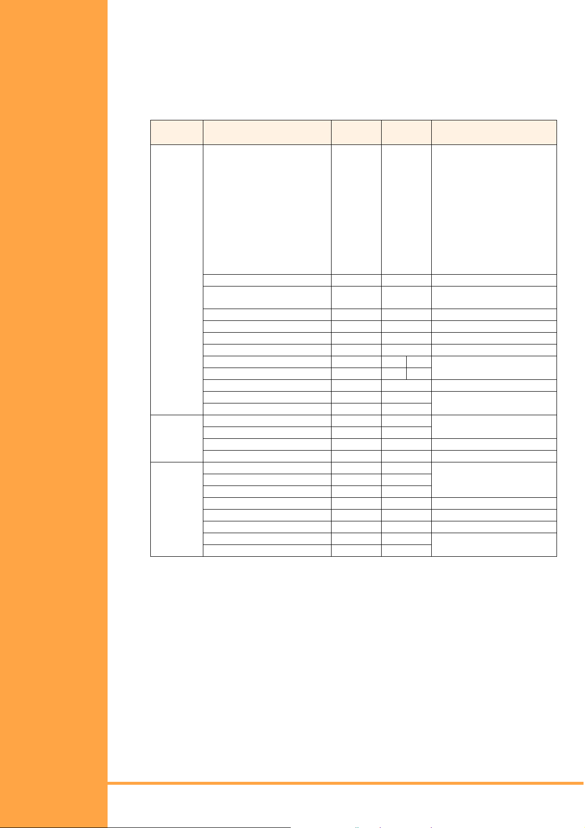
Figure Figure 1-2: NEC Xen Alpha System Block Diagram, Pg 11 represents an installed
system. This diagram shows the ETUs that can be installed in the KSU and the number of
channels that are supported when the ETU is installed.
Figure 1-2: NEC Xen Alpha System Block Diagram
Installation Manual
A6-506000-642-01
System Overview Page 11
• • •
Page 22
S
ECTION
R
EQUIREMENTS
S
PECIFICATIONS
6
&
This section provides cabling requi rements and speci ficat ions for various equi pment use d in
the Xen Alpha system.
! BRT(1)-B13 ETU
! COI(2)-B13 ETU
! DPH-B13 ETU
! ESI(8)-B13 ETU
! SLI(2)-B 13 E T U
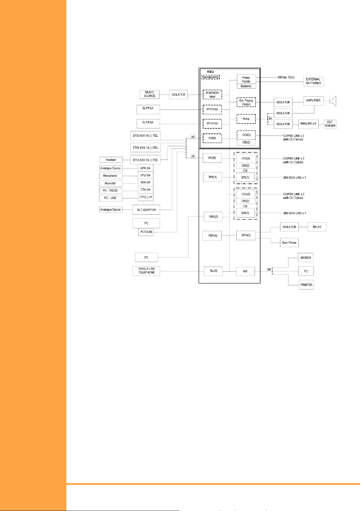
The KSU is connected with each of the Multiline Telephones and Single Line Telephones by
a separate twisted 1-pair cable or 2-pair cable (only for Multiline Telephones). (Refer to
Table 1-1:: Multiline Telephone Loop Resistance and Cable Length, Pg 12 for the loop
resistance and cabling requirements for Multiline Telephones and adapters.)
Table 1-1: Multiline Telephone Loop Resistance and Cable Length
Terminal or Adapter
Maximum Loop
Resistance (Ohms)
Maximum Metres by
Twisted 1-Pair Cable
24 AWG
Maximum Metres by
Twisted 2-Pair Cable
24 AWG
DTB-16-1A ( ) TEL
DTB-16D-1A ( ) TEL
DTU-8-1A ( ) TEL
DTU-8D-1A ( ) TEL
DTU-16D-1A ( ) TEL
DTU-32D-1A ( ) TEL
SL T (1)-U1 3 ADP
ETW-8E-1A (SW) TEL
ETW-16C-1A (SW) TEL
ETW-16D-1A (SW) TEL
!
Note 1: The length specified for the SLT Adapter is the length between the SLT
26 135 270
26 135 270
35 180 300
35 180 300
26 135 270
21 110 215
35 180 300
35 180 300
26 135 270
21 110 215
Adapter and the ESI port.
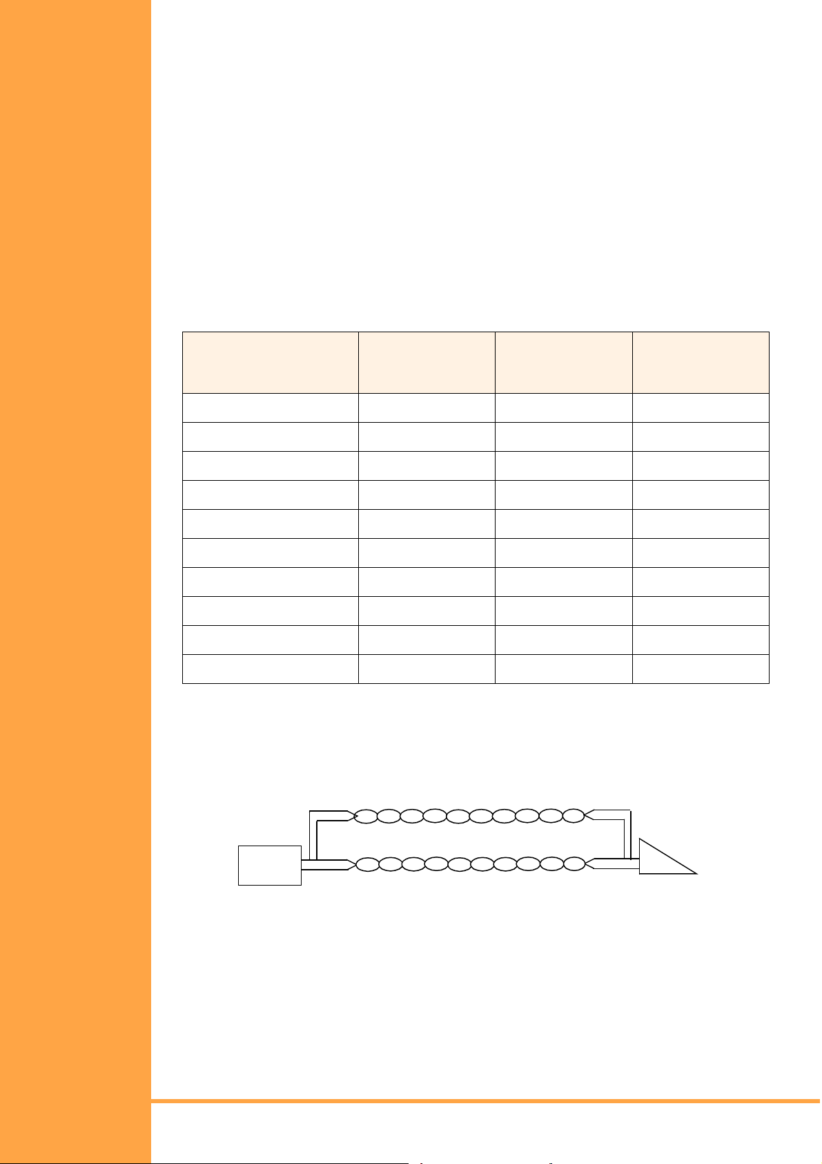
Figure 1-3: Connecting the ESI to the Multiline Telephone Using
Twisted 2-Pair Cable
Twisted 2-Pair Cable
ESI
Multiline Telephone
Page 12 System Overview
Installation Manual
• • •
A6-506000-642-01
Page 23
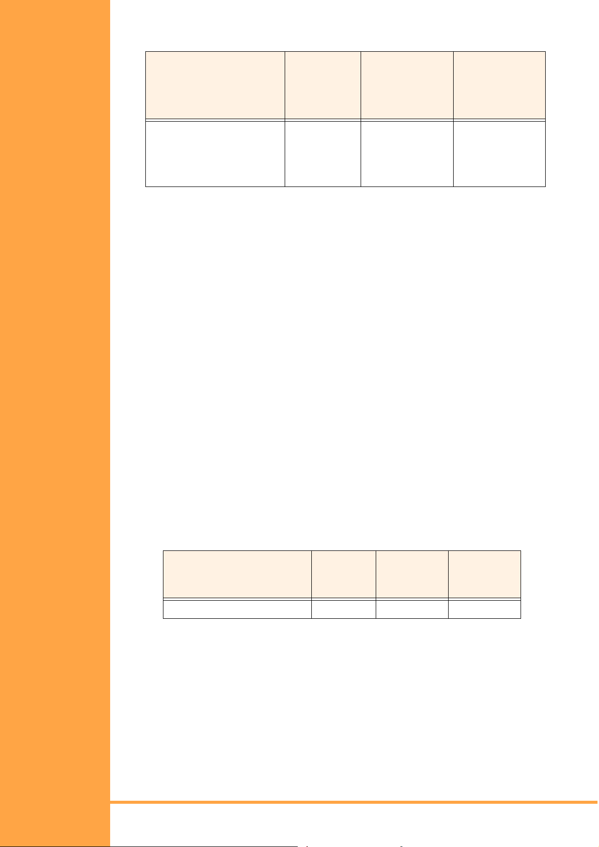
Table 1-2: Cable Connection Between the Analogue Port Adapter and the
Single Line Telephone
S
ECTION
P
OWER
R
EQUIREMENTS
7
Maximum Loop
Resistance from
Connected Equipment Cable
APR-UA ADP
SLT(1)-U13 ADP
SLI(2)-U13 ETU
Note 1: Mixing digital and analogue ports through the same 25-pair cable runs is not
!
Twisted Pair 600 200 m
Twisted Pair 600 200 m
Twisted Pair 600 200 m
Connected
Equipment to
Telephone
Maximum Feet by
Twisted 1-Pair
Cable
(24 AWG)
recommended.
Note 2: The Maximum Loop Resistance includes the internal resistance of the
SLT device.
Power Supply Inputs
The AC input requirements for the Xen Alpha system are listed bel ow:
AC Input
! 250 Vac + 10/-15 %
! 50 Hz ± 10%
! Single Phase
! 10A Circuit
! A dedicated outlet, separately fused and grounded, is required.
Power Supply Consumption
The power consumption for the Xen Alpha system is listed in Table 1-3:: Power
Consumption, Pg 14.
Table 1-3: Power Consumption
Maximum
KSU
B614-B13 KSU 0.6A 24 W 144 W
RMS
Current
Watts Used
(Idle)
Watts Used
(Maximum)
Installation Manual
A6-506000-642-01
System Overview Page 13
• • •
Page 24

S
ECTION
E
NVIRONMENTAL
C
ONDITIONS
8
Table 1-4:: Wei ghts and Dimensi ons, Pg 15 shows shipping wei ght, hei ght, wi dth, and dept h
of each InfoSet KSU, Multiline Telephone, and adapter.
Table 1-4: Weights and Dimensions
Unit
Shipping
Weight*
Height Width Depth
ACA-UA Unit
ADA-UA Unit
APR-UA Unit
B614-B13 KSU
BRT(1)-B13 ETU
CID(2)-B13 UNIT
COI(2)-B13 ETU
CTA-UA Unit
DPH-B13 ETU
DTB-16-1A(BK)/(WH) TEL
DTB-16D-1A(BK).(WH) TEL
DTU-16D-1A (WH) TEL
DTU-32D-1A (WH) TEL
DTU-8-1A (WH) TEL
638 g 86 mm 107 mm 133 mm
65 g 29 mm 59 mm 99 mm
122 g 66 mm 59 mm 121 mm
6500 g 320 mm 385 mm 124 mm
130 g 93 mm 138 mm 21 mm
98 g 60 mm 110 mm 28 mm
185 g 93 mm 138 mm 29 mm
122 g 66 mm 59 mm 121 mm
140 g 93 mm 138 mm 21 mm
1100 g 231 mm 168 mm 86 mm
1180 g 231 mm 168 mm 86 mm
1233 g 123 mm 197 mm 235 mm
1361 g 123 mm 220 mm 235 mm
1163 g 123 mm 197 mm 235 mm
DTU-8D-1A (WH) TEL
ETW-16C-1A (SW) TEL
ETW-16D-1A (SW) TEL
ETW-8E-1A (S W) TEL
ESI(8)-U13 ETU
HFU-UA (WH) Unit
MIF-B13 ETU
PBR-B13 ETU
SLI(2)-B13 ETU
SL T(1 )-U13 ADP
TRF-B13 ETU
VMS(2)-B13 ETU
WMU-UA Unit
1233 g 123 mm 197 mm 235 mm
992 g 101 mm 175 mm 223 mm
1106 g 101 mm 205 mm 223 mm
907 g 101 mm 175 mm 223 mm
185 g 93 mm 138 mm 20 mm
201 g 86 mm 107 mm 133 mm
340 g 93 mm 138 mm 21 mm
70 g 75 mm 65 mm 20 mm
170 g 93 mm 138 mm 24 mm
255 g 45 mm 70 mm 120 mm
100 g 93 mm 138 mm 15 mm
TBA TBA TBA TBA
301 g 104 mm 151 mm 180 mm
* Shipping weight includes the shipping carton.
Page 14 System Overview
Installation Manual
• • •
A6-506000-642-01
Page 25

S
ECTION
O
UTSIDE LINE
T
9
YPE
The following outside line types can be used with the InfoSet system.
! 2-wire, Loop Start Trunks
! ISDN-BRI Trunks
S
ECTION
N
10
ETWORK
C
ONTROL
&
Tra nsmis sion, Network & Control Specifications
Transmission
• Data Length
From Multiline Telephone to ESI(8)-B13 ETU: 23 bits
From ESI(3)-B13 ETU to Multiline Telephone: 23 bits
• Data Transmission Rates:
Between ESI(3)-B13 ETU and Multiline Telephone: 184K bps (voice and signaling)
• Scanning Time for each Multiline Telephone: 32 ms.
Network
Time Division Multiplexing allows transmission of a number of separate data, voice and/or
video simultaneously over one communications medium. The information below indicates
the specifications the InfoSet syst em uses for switching, clock, data bus, time-frame.
• TDM Switching: PCM (µ Law)
• TDM Clock: 2.048 MHz
• TDM Data Bus: 8 bit
• TDM Time-frame: 125 µs
Control
This section indicates the speed and capacities of the control.
• Control: Stored program with distributed processing
• Central Processor: 8-bit microprocessor
• Clock: 12.288 MHz
• Sub-processor: 8-bit microprocessor
• Multiline Telephone: 8-bit microprocessor
• SLT Adapter: 4-bit microprocessor
Installation Manual
A6-506000-642-01
System Overview Page 15
• • •
Page 26

Telephone
The voltage, current, ring signal information for the InfoSet multiline telephones, single line
telephone equipment, and APR units are listed below.
• Multiline Telephone
Voltage: -11 " -26 Vdc
Maximum Current: 250 mA
• Single Line Telephone
Standard 2500 Set: 500 type network
Nominal Current: 35 mA
Ring Signal: 56 Vac RMS @ 20 Hz
• SLT(1)-U13 ADP
Standard 2500 Set: 500 type network
Nominal Current: 30 mA
Ring Signal: 56 Vac RMS @ 20 Hz
•APR-UA Unit
Standard 2500 Set: 500 type network
Nominal Current: 30 mA
Ring Signal: 70 Vac RMS @ 18 Hz
S
ECTION
D
IALLING
S
PECIFICATIONS
11
Dial Pulse Address Signaling
Dial Pulse Signaling is a type of address signaling that uses dial pulses (regular momentary
interruptions) to signal the equipment. In the InfoSet system, the following Dial Pulse
specifications are used.
! Pulse Rate: 10 ± 0.5 pps/20 ± 1.0 pps
! Percent Break: 60 ± 1.5%
! Inter-digit Interval: 10 pps/20 pps 770 ms
"
830 ms
Dual-Tone Multifrequency (DTMF) Address Signaling
DTMF signaling is a term that describes push button or Touchtone dialling. When a key on a
telephone is pushed, two tones (one high frequ ency and one low f requency) are provi ded. In
the InfoSet system, the following DTMF specifications are used.
! Frequencies
Two sinusoidal frequencies are provided, one from the high frequency group and one
from the low frequency group.
! Frequency Deviation: Less than ±1.0%
!
Signal Level:
Nominal level per frequency: -6 " -4 dBm
Minimum level per frequency: Low Group: -10 dBm
High Group: -8 dBm
Maximum level per frequency: 0 dBm
Page 16 System Overview
Installation Manual
• • •
A6-506000-642-01
Page 27

!
Rise Time: Within 5 ms
! Duration of Dual Frequency Signal:
• 110 ms default/60 ms. minimum
! Inter-digital Time: 80 ms default/70 ms minimum
Nominal High Group
Frequencies (Hz)
1209 1336 1477
697 123
S
ECTION
C
12
E
XTERNAL
E
QUIPMENT
ONNECTION
Nominal Low Group
Frequencies (Hz)
770 456
852 789
941 ✻ 0#
Music Sources for Music on Hold via KSU
! Auxiliary Input: 0.6V PPS Signal Level
! Input Impedance: 600 <Symbol>W
Music Source for Station Background Music via KSU
! Auxiliary Input: 0.6V PPS Signal Level
! Input Impedance: 6 00 <Symbol>W
External Paging (Audio) via KSU
! Output Power: –10 dBm Signal Level
! Output Impedance: 600 <Symbol>W
External Tone Ringer/Night Chime Output
! Output Level: –10 dBm
! Output Impedance: 600 <Symbol>W
! Relay Contact Rating: 500 mA, 24 Vdc
SMDR Output
! Female Connector (System Output) Standard RS-232C
PC Connection
! Female Connector (System Output) Standard RS-232C
Relay Contact
! All Relay Contact Ratings: 500 mA, 24Vdc
Installation Manual
A6-506000-642-01
System Overview Page 17
• • •
Page 28

S
ECTION
13
B
ATTERY
B
ACKUP The Xen Alpha system has battery backup functions for system backup and for
memory backup.
System Backup
During a mains power failure, the system’s operation can be backup up using rechargeable
batteries. The internally mounted backup batteries can support all system operations for
approximately 30 minutes under average conditions. If longer backup duration’s are
required, larger externally mounted batteries can be connected. The recommended battery
size, as shown in Table 1-5:: Internal and External Battery Specifications, Pg 20 below, can
support all system operations for approximately 4 hours under average conditions.
Table 1-5: Internal and External Battery Specifications
Specification Internal Battery External Battery
Weight
Terminal Type
Size: Length
Width
Height
Leaded, JST VHR-2N Leaded, JST VHR-2N
350 g 2.6 kg
96 mm
25 mm
62 mm
151 mm
65 mm
94 mm
Max. Discharge Current
Voltage Rating
Current Capacity
Minimum Backup Duration
2.1 A 2.1 A
12 V 12 V
0.7 Ah 6.5 Ah
30 Mins 4 Hrs
CAUTION
Do not short circuit batteries. The battery could explode and cause damage
to personnel and equipment.
Danger of explosion i f battery is incorrec tly replaced. Replace only with the same
or equivalent type recommended by the manufacturer . Dispose of used batteries
according to the manufacturer’s instructions.
Memory Backup
The B614-B13 KSU has a Lithium battery installed to provide backup of system memory.
The following functions will be retained for a minimum of 3 months when the battery is
fully charged.
! Background Music
! Call Forwarding
! Clock/Calendar
! Do Not Disturb (DND)
! Last CO/PBX Redial
! Message Waiting
! Room Monitor
! Speed Dial Memories (System and Station)
! System Programming
! Timed Alarm
! Trunk to Trunk Transfer Destinations
! Volume Control/LCD Contrast
! Microphone Status
Page 18 System Overview
Installation Manual
• • •
A6-506000-642-01
Page 29
S
ECTION
14
V
ISUAL
A
UDIBLE
I
NDICATIONS
&
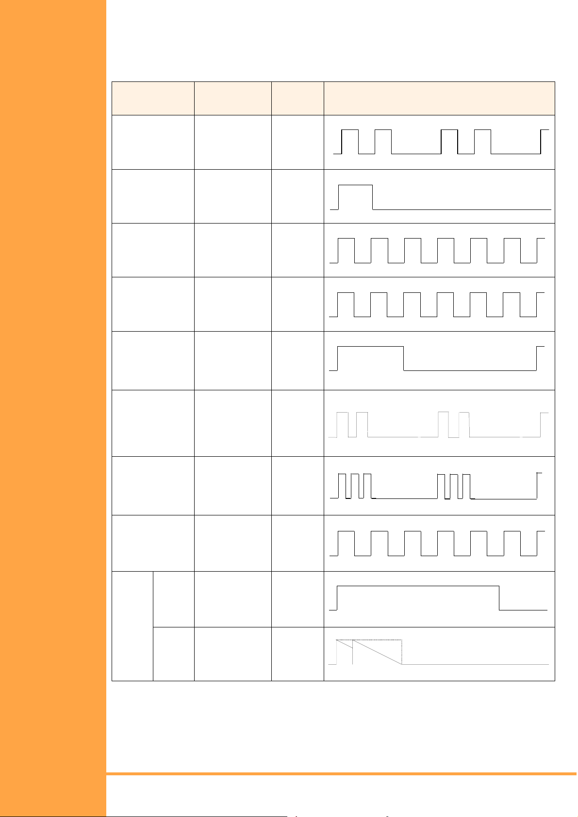
Tone Patterns Table
System Tone
(Fixed)
Automatic Callback 500 Hz (I)
Barge-In Tone 440 Hz N/A
Busy Tone 480 Hz
Call Waiting Tone 440 Hz N/A
Frequency (Hz)
(Fixed)
540 Hz (D)
620 Hz
Table 1-6: Tone Patterns
Modulation Cycle
N/A
N/A
ON
OFF
ON
OFF
ON
OFF
ON
OFF
0.5 sec.
0.5 sec.
1 sec.
0.5 sec.
0.5 sec.
0.5 sec.
0.5 sec.
CO/PBX Ring
Tone A
CO/PBX Ring
Tone B
CO/PBX Ring
Tone C
CO/PBX Ring
Tone D
Doorphone1Chime
Tone
High:
1024 Hz/1285 Hz (I)
1100 Hz/1400 Hz (E)
Low:
480 Hz/606 Hz (I)
520 Hz/660 Hz (E)
High:
1024 Hz/1285 Hz (I)
1100 Hz/1400 Hz (E)
Low:
480 Hz/606 Hz (I)
520 Hz/660 Hz (E)
High:
1024 Hz/1285 Hz (I)
1100 Hz/1400 Hz (E)
Low:
480 Hz/606 Hz (I)
520 Hz/660 Hz (E)
High:
1024 Hz/1285 Hz (I)
1100 Hz/1400 Hz (E)
Low:
480 Hz/606 Hz (I)
520 Hz/660 Hz (E)
N/A N/A
16
16
16
16
ON
OFF
.375 sec.
ON
OFF
ON
OFF
0.5 sec.
ON
OFF
ON
OFF
2 sec.
4 sec.
.250 sec.
.250 sec.
.125 sec.
0.5 sec.
Installation Manual
A6-506000-642-01
Busy
Chime
1400 Hz/1100 Hz
(I & E)
N/A
ON
Tone
1400 Hz
OFF
System Overview Page 19
• • •
1100 Hz
Page 30
System Tone
(Fixed)
Frequency (Hz)
(Fixed)
Modulation Cycle
Doorphone2Chime
N/A N/A
Tone
Busy
Chime
Tone
Hold Alarm 1024 Hz (I)
Howler Tone 2400 Hz
1024 Hz (I)
1100 Hz (E)
1100 Hz (E)
(I & E)
Incoming Dial Tone 360 Hz/440 Hz
(I & E)
Incoming Ring Transfer 480 Hz/606 Hz (I)
520 Hz/660 Hz (E)
N/A
N/A
16 100% AM
N/A
16
ON
OFF
.250 sec.
ON
OFF
0.5 sec.
ON
OFF
ON
OFF
ON
OFF
0.5 sec.
ON
.250 sec.
0.5 sec.
.032 sec.
.032 sec.
Continuous
Internal Ring Tone 500 Hz (I)
540 Hz (E)
Key Tone 1100 Hz (I & E) N/A
Recall T one 1024 Hz (I & E) N/A
Reorder Tone 480/620 Hz N/A
Ringback Tone for
External Speaker CO/
440 Hz/480 Hz
(I & E)
PBX Ring Tone
N/A
N/A
OFF
0.5 sec.
ON
OFF
.070 sec.
ON
OFF
0.5 sec.
ON
OFF
.250 sec.
ON
OFF
ON
OFF
0.5 sec.
0.5 sec.
0.5 sec.
.250 sec.
1 sec.
2 sec.
Ringing Transfer Alarm 1024 Hz (I)
1100 Hz (E)
Set Tone 1 800 Hz
(I & E)
N/A
N/A
ON
OFF
ON
OFF
0.5 sec.
0.5 sec.
.700 sec.
Page 20 System Overview
Installation Manual
• • •
A6-506000-642-01
Page 31

System Tone
(Fixed)
Frequency (Hz)
(Fixed)
Modulation Cycle
Set Tone 2 500 Hz (I)
540 (E)
Timed Alarm 1024 Hz (I)
1100 Hz (E)
Tone Override 500 Hz (I)
540 HZ (E)
Trunk Queuing 500 Hz (I)
540 HZ (E)
N/A
N/A
N/A
N/A
0.5 sec.
ON
OFF
.250 sec.
ON
OFF
2 sec.
ON
OFF
0.5 sec.
ON
OFF
.125 sec.
0.5 sec.
Installation Manual
A6-506000-642-01
System Overview Page 21
• • •
Page 32

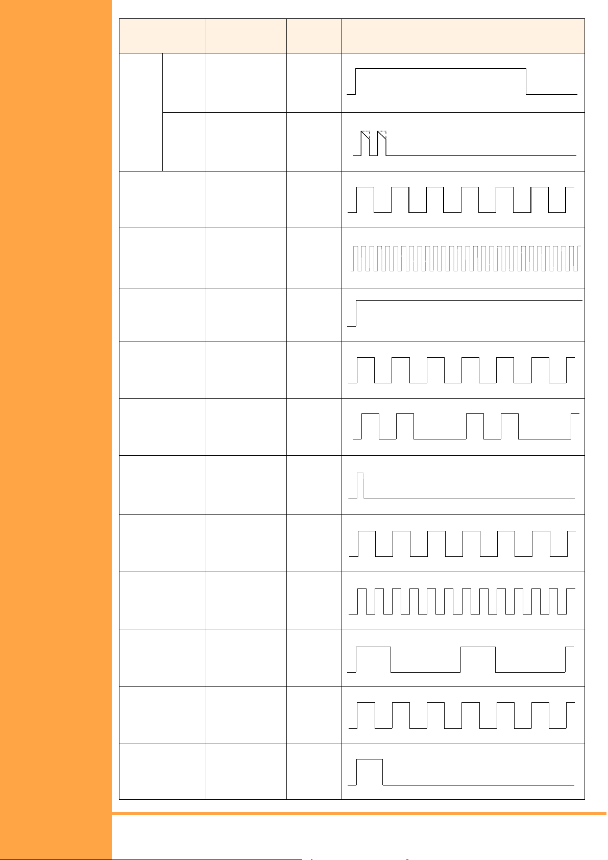
Multiline Terminal Flash Patterns Table
Table 1-7: Multiline LED Patterns
LED Condition Col. Flash Pattern
Line Key
Microphone
ICM
Large LED
Speaker
Conference
I-Use
Busy
Incoming Call
I-Hold
Call Hold
Hold Recall
Transfer Recall
ON
Monitored
I-Use
ICM Incoming Call
Incoming Internal Call
Incoming CO Line
Voice Mail Message
ON
System Data Entry
Monitor
Conference in
Progress
All Conference Circuits
in Use
Hold Conference Call
ICM Call Hold
SPD Confirmation
Green
Red
Red
Green
Red
Green
Green
Red
Red
Red
Red
Red
Green
Red
Red
Red
Red
Red
Red
Red
Red
Red
Answer
Call
Function
LNR/SPD
BLF or DSS
Key
Incoming Trunk
Preset
Trunk Selected
Preset
No Trunks A v ailable
Callback Set
DND, Call FWD
Auto Redial Set
ON (to Set Function)
CO Line Key Seized
Exclusive Ho ld
Use, Hold, ICM Called
DND, Call Fwd All Set
Special Mode (Wh ile
pressing FNC key or
going off-line)
Red
Red
Green
Red
Red
Red
Red
Red
Red
Green
Green
Red
Red
Red
0 0.5 1.0 1.5 2.0 sec
Page 22 System Overview
Installation Manual
• • •
A6-506000-642-01
Page 33

DSS/BLF LED Indications Table
Table 1-8: DSS/BLF LED Indications
Function Colour Status
Idle
Talking
Hold
FWD All & DND
Other Use (Multiline Terminal is in off-line
mode, the station user is programming,
Feature Access/One-Touch Key
programm ing, et c.)
OFF
Red ON
Red ON
Red (flashing) ON
Red (flashing) ON
Installation Manual
A6-506000-642-01
System Overview Page 23
• • •
Page 34

Page 24 System Overview
Installation Manual
• • •
A6-506000-642-01
Page 35

Installation Manual
A6-506000-642-01
System Overview Page 25
• • •
Page 36

This page is intentionally blank.
Page 26 System Overview
Installation Manual
• • •
A6-506000-642-01
Page 37

C
HAPTER
2
KSU Installation
Xen Alpha Release 1.0
S
ECTION
G
ENERAL
I
NFORMATION
S
ECTION
P
REPARATION
1
This section provides the requirements for installing the system. The installer should be
familiar with this section before installing the system.
2
S
ITE
The technician should plan the installation before actual work begins. Advanced planning
will minimize time, cost and disruption of the customer’s business activities. Additional
benefits include flexibility for changes and expansion, efficient maintenance and increased
customer satisfaction.
Precautionary Information
The following warnings shall be observed during installation:
1. Never install telephone wiring during a lightning storm.
2. Never install telephone jack s in wet locat ions unles s the j ack is speci fical ly desi gned for
wet locations
3. Never touch uninsulated telephone wires or terminals unless the telephone line has
been disconnected at the network interface.
4. Use caution when installing or modifying telephone lines.
Site Survey
Inmost cases, a survey of the customer’s premises is needed to develop cost estimates of
the installation. Preliminary information is used to determine the placement of the Main
Distribution Frame (MDF). A second visit to the site may be necessary to obtain the exact
dimensions of the area selected for MDF, cable lengths and possible IDF (intermediate
Distribution Frame) locations.
Site Limitations
Installation of a telephone system is seldom a routine procedure. The uniqueness of each
customer’s situation requires a tailored approach to each job. In selecting a permanent site
for the MDF, the technician may encounter problems such as, but not limited to th e following:
! Limited space is available and must be used regardless of its sui tability.
! The available space may be adequate, but may pose one or more environmental
hazards.
! The proposed location has limitations. Such as insufficient lighting or the lack of a
suitable ground for grounding the KSUs.
Whatever the nature of the adversities encountered, the technician must make the
necessary decisions to arrive at the best possible solution for installing the equipment. It is
beyond the scope of this document to cover all possible situations, precautions and actions.
Installation Manual
A6-506000-642-01
KSU Installation Page 23
• • •
Page 38

Site Selection Conditions
KSU Installation Site
The following conditions should be met at the site selected for the KSU.
! The KSUs should be wall mounted to protect against accident or flooding.
! The KSU should not be located directly beneath pipes, due to the possibility of leaks or
condensation causing damage to the equipment.
! The area where the KSU is to be located must be free of corrosive and inflammable
gases, excessive chemical or industrial dusts and other materials that could cause a
hazard to personal or to the proper functioning of the equipment.
! Operating ambient temperature and humidity must be within the limits specified in
Section 2.6 – Environmental Conditions in this chapter.
! The operation of the system is virtually noiseless and allows a wide selection of
installation sites. Care should be taken to ensure the KSUs do not present a hazard to
office traffic. For purposes of economy, a central location to minimise cabling is
often used.
! The basic KSU weighs approximately 4 Kg. Select a strong wall for mounting purposes.
! Place the KSU according tot he following spacing specifications
• Space distance between the KSU and the ceiling: 50 cm or more
• Space distance on both sides of the KSU: 30 cm or more
• Space distance on front of KSU: 50 cm or more
! Avoid connection of the KSU to an AC receptacle used in common with any other
device (computer, facsimile machine, copier, etc.)
! Ensure that any AC Outlet to be connected is properly ground ed.
! Avoid connection of KSU near radio receivers or electrical noise generators (e.g.
welding equipment, machinery).
CAUTION
1. The socket outlet shall be installed near the equipment and shall be easily accessible.
2. Plug the system into the mains supply (240 V ac) before terminating a
telecommunications network conductor to the system.
3. Danger of explosion if batteries are incorrectly replaced. Replace only with the same or
equivalent type recommended by the manufacturer. Dispose of used batteries
according to the manufacturers instructions
Multiline Telephone Installation Site
The following conditions should be met at the site select ed for ML Ts.
! Ensure the cable length and line resistance (loop), between the KSU and the
telephones comply with the specifications shown in Table 1-1: Multiline Telephone Loop
Resistance and Cable Length Multiline Telephone Loop Resistance and Cable Length.
! Some devices require an external power supply. Select a place where they can be
easily connected to an AC outlet.
! Telephones intended for handsfree use should be kept away from areas subject to loud
noise or echoing.
Page 24 KS U Installation
Installation Manual
• • •
A6-506000-642-01
Page 39

S
ECTION
I
NSTALLING THE
KEY S
U
NIT
ERVICE
(KSU)
3
Installation Precautions
Before installation and cabling of the KSU, observe the below precautions.
! Before starting the work, be sure the KSU power switch is OFF and disconnect the
power cord from the AC outlet.
! Do not directly touch the soldered surfaces of the KTUs with you hands.
! Extreme care must be taken to avoid STATIC DISCHARGE when handling ICs and
KTUs – an earthed wrist strap must be worn.
The Key Service Unit
The B614-B13 KSU is the system cabinet that houses a power supply, battery backup and
fixed slots for installing option/expansion cards. The KSU is wall mounted. (Refer to Figure
2-1:: Front View of a KSU, Pg 25.)
Figure 2-1: Front View of a KSU
Installation Manual
A6-506000-642-01
KSU Installation Page 25
• • •
Page 40
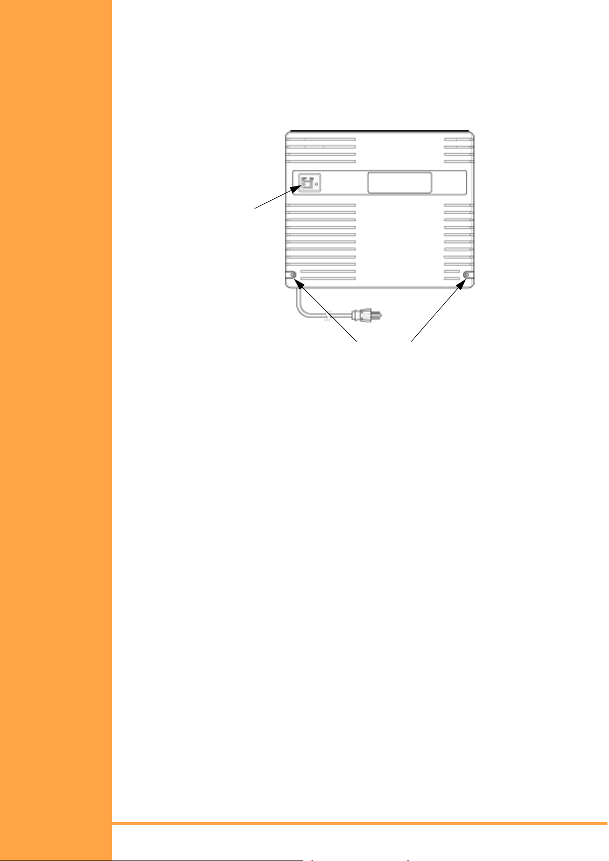
Removing the KSU Cover
Before wall mounting the KSU, the KSU cover must be removed. Below is a diagram
showing how to remove the cover of the KSU.
1. Remove the cover by loosening the two bottom screws with a philips head screwdriver
(the screws remain in the cover to keep from misplacing them). Pull the cover away
from the KSU and lift upward.
ON/OFF
Switch
Loosen or Tighten Screws
Figure 2-2: How to Remove the KSU Cover
2. To replace the cover, locate the tabs on the top of the cover into the slots in the top of
the base and then push the bottom of the cover inwards. Tighten the t w o cover screws.
Page 26 KS U Installation
Installation Manual
• • •
A6-506000-642-01
Page 41

Wall Mounting the KSU
Before wall mounting the KSU, it is recommended that the wall mounting screws be
attached to the piece of plywood (13 mm thick or more) or attached to a sturdy wall.
1. Using two of the four screws (provided with the KSU) attach the wall mount template
to the wall. (Refer to Figure 2-3:: Attaching th e Wa ll Mounting Brac ket for the KSU to the
Wall, Pg 27.)
Figure 2-3: Attaching the Wall Mounting Bracket for the KSU to the Wall
2. While holding the KSU, hang the upper two openings that are located in the KSU base
over the wall mount template. (Refer to Figure 2-4:: Attaching the KSU to the Wall
Mount Template, Pg 27.))
Installation Manual
A6-506000-642-01
Figure 2-4: Attaching the KSU to the Wall Mount Template
KSU Installation Page 27
• • •
Page 42

3. Using the other two provided screws, secure the KSU to the wall mount template by
screwing the lower two openings located in the KSU base. (Refer to Figure 2-5::
Securing the KSU to the Wall Mount Template, Pg 28.)
Figure 2-5: Securing the KSU to the Wall Mount Template
Installing or Replacing the Internal Backup Batteries
These batteries provide power for the system in case of a power outage. Fully charged
batteries provide power for approximately 30 minutes.
1. Be sure the system is turned off during the installation process.
2. Remove the cover by loosening the two bottom screws with a philips head screwdriver
(the screws remain in the cover to avoid misplacing them). Pull the cover away from the
KSU and lift upward.
3. Remove the screw that is attached t o the grounding cabl e and loosen the s econd screw
that secures the metal plate to the batteries. Slide the metal plate until it clears the
remaining screw and lift upward to remove the metal plate.
4. If replacing existing batteries, detach the battery cables from the connector terminals
CN3 (BATT1) and CN4 (BATT2). Lift out the old batteries.
5. Insert the new batteries into the slots. Place the notched end of the battery toward the
casing on the KSU. Place the battery cables between the inside of the battery and the
posts located on the inside of the battery casing.
Figure 2-6: Inserting a New Battery in the KSU Unit
Page 28 KS U Installation
Installation Manual
• • •
A6-506000-642-01
Page 43

6. Replace the metal plate on top of the new batt eries. Pla ce the grounding cabl e on top of
the hole and tighten the screw using a philips head screwdriver.
7. Attach the battery connectors to CN3 (BATT1) and CN4 (BATT2) battery terminals.
Insert the battery connectors over either battery terminal. The connector tab should be
placed over the terminal tab. There is only one direction the tabs can be placed into the
connector terminals, therefore you canno t attach them incorrectly.
Figure 2-7: Attaching the Battery Connectors
8. Attach the cover and tighten the screws.
9. Turn the power on.
IMPORTANT SAFEGUARDS FOR BATTERY DISPOSAL
DO NOT PLACE USED BATTERIES IN YOUR REGULAR TRASH! THE PRODUCT YOU
PURCHASED CONTAINS A NICKEL-CADMIUM OR SEALED LEAD BATTERY. NICKELCADMIUM OR SEALED LEAD BATTERIES MUST BE COLLECTED, RECYCLED OR
DISPOSED ON IN AN ENVIRONMENTALLY SOUND MANNER.
The incineration, land filling or mixing of nickel-cadmium or sealed lead batteries with the
municipal solid waste stream is PROHIBITED BY LAW in most areas. Contact your local
solid waste management officials for other information regarding the environmentally sound
collection and disposal of the battery.
Installation Manual
A6-506000-642-01
CAUTION
Do not short circuit batteries. The battery could explode and cause damage to personnel
and equipment.
Danger of explosion if battery is incorrectly replaced. Replace only witht he same or
equivalent type recommended by the manufacturer. Dispose of used battereis according to
the manufacturer’s instructions.
KSU Installation Page 29
• • •
Page 44

Connecting External Backup Batteries
1. Disconnect the Built-in Backup Battery Cables from CN3 and CN4 on the Power
Supply. Position the loose battery cables safely inside the KSU.
2. Mount the external battery into the External Battery Cabinet (AKB-A-ZD KTU), as
follows:
Note: Two batteries must be connected per KSU and each cabinet houses just one
battery.
a.) Remove the four cover screws.
b.) Pass the battery cables through the hole in the left side of the cabinet and connect
to the battery terminals.
Note: RED CABLE TO ⊕
BLUE CABLE TO −
Figure 2-8:
c.) Mount the battery into the cabinet and secure it using the U-shaped bracket with
two screws.
Figure 2-9:
d.) Secure the battery cables using the grommet supplied.
Figure 2-10:
Page 30 KS U Installation
Installation Manual
• • •
A6-506000-642-01
Page 45

3. Mount the two External Battery Cabinets close to the KSU using the wood screws
supplied and replace the cover using the four screws. (Refer to Figure 2-11:: Mounting
the External Battery Cabinet, Pg 31.)
Figure 2-11: Mounting the External Battery Cabinet
4. Connect the two external cable assemblies to CN3 and CN4 on the power supply.
(Refer to Figure 2-12:: Connecting External Batteries, Pg 31.)
Figure 2-12: Connecting External Batteries
Installation Manual
A6-506000-642-01
KSU Installation Page 31
• • •
Page 46

Grounding Requirements
The KSU must be properly grounded. This can be achieved by a c orr ectly wi red AC outl et. I f
there is any uncertainty, obtain advice from a licensed electrical contractor. Where a ground
(other than conduit ground) is used, a grounding terminal is provided on a B614-B13 KSU.
(Refer to Figure 2-13:: KSU Grounding, Pg 32.)
Figure 2-13: KSU Grounding
Connecting the B614-B13 KSU
The CPU is the central processing unit (CPU). An 8-bit microprocessor executes the
programs stored on the ROM ICs to control the whole system, while transferring data to and
from other KTUs.
The KSU consists of a main control section and a Time Division Switch (TDSW) section. It
also has an external ringer interface six 4-party conference circuits, two CO/PBX interfaces,
six station interfaces and two power failure transfer circuits.
The RAM memory, on the CPU is back up with a non- rechargeable lithium battery whi ch will
retain the memory for up to 18 months.
Switch Settings
Before programming System Data, the non-rechargeable lithium battery must be switched
on (SW1→HOLD) to allow memory content retention in case of a power failure or brownout.
Failure to activate the backup battery circuit may result in System Data being reset to the
default values, the status of all stations will reset to the default values and the data
programmed on the station may clear if a power failure or brownout occurs. (If programming
using a Multiline Terminal, refer to Chapter 2, Programming in this manual for instructions.)
!
NOTE: Wait at least 30 seconds after turning on system power before changing
memory switch SW1 from CLEAR to HOLD.
When the KSU is removed for long term storage, switch off the lithium battery (SW1→CLEAR).
This will prevent the battery from constantly discharging. The battery, when fully charged will
retain memory contents for a minimum of three months. (Refer to
Settings, Pg 33
Table 2-1: KSU Switches and Connections, Pg 33
and
Figure 2-14:: KSU Switch
.)
To clear the system memory, use the foll owing procedure.
1. Turn syste m power OFF.
2. Change SW1 to CLEAR position.
3. Turn syste m power ON.
Page 32 KS U Installation
Installation Manual
• • •
A6-506000-642-01
Page 47

4. After waiting at least 30 seconds, change SW1 to HOLD position.
Figure 2-14: KSU Switch Settings
Table 2-1 KSU Switches and Connections
Name Default Setting Description/Purpose
SW1
CN1
CN2
CN3
CN4
CN5
CN6
CN7
CN8
CN9
CN11
CN12
CN13
CN14
CN15
CN16
CN17
CN18
CN20
CLEAR
ST 1"6
EXT.SPK
MOH/BGM
CO 1"2
FAX/PFT 1"2
RLY
ESI
DPH
VRS
VMS
TRF
PBR
External ROM
MIF
SLI
COI
BRT
COI
BRT
CID
PSU
System Memory Battery Backup (Hold/Clear)
ESI Station Ports 1"6
External Paging Speaker
Music on Hold and Background Music Source
Analogue Trunks 1"2
Fax or Power Fail Transfer Ports 1"2
External Paging Amplifier or External Ringer Control Relay
ESI(8)-B13 ETU
DPH-B13 ETU
VRS-B13 ETU (Future Use)
VMS(2)-B13 ETU
TRF-B13 ETU
PBR-B13 ETU
Flash ROM Card
MIF-B13 ETU
SLI(2)-B13ETU
COI(2)-B13 ETU
BRT(1)-B13 ETU
COI(2)-B13 ETU
BRT(1)-B13 ETU
CID(2)-B13 ETU
Power Supply CN103
Installation Manual
A6-506000-642-01
KSU Installation Page 33
• • •
Page 48

Telephone Connections
The B614-B13 ETU supports the connection of 6 digital extensions via CN1. Each port
requires a single twisted pair cable and the connection is not polarity conscious. (Refer to
Figure 2-15:: Telephone Connection, Pg 34)
Figure 2-15: Telephone Connection
Exchange Line connection
The B614-B13 ETU supports the connection of 2 analogue exc hange lines (Cent ral Of fice or
PABX) via CN2. This 2-wire connection is not polarity conscious. (Refer to Figure 2-16::
Exchange Line Connection, Pg 34.)
Figure 2-16: Exchange Line Connection
Power Fail Telephone and Fax Connection
The B614-B13 ETU supports the connection of 2 analogue telephones via CN2 for use
during period of power failure (i.e. when AC power is lost and the system backup batteries
are depleted). Connection of each 2 wire analogue telephone is shown in Figure 2-17::
Power Fail Telephone and Fax Connection, Pg 35. In the event of a power failure the
analogue telephones are connected immediately to a CO/PBX line as follows:
FAX/PFT1 ! CO1
(CN2, pins 5-6)
FAX/PFT2 ! CO2
(CN2, pins 7-8)
A detailed explanation of the operation and usage of Power Fail Telephones is given at the
end of Section 5.
Page 34 KS U Installation
Installation Manual
• • •
A6-506000-642-01
Page 49
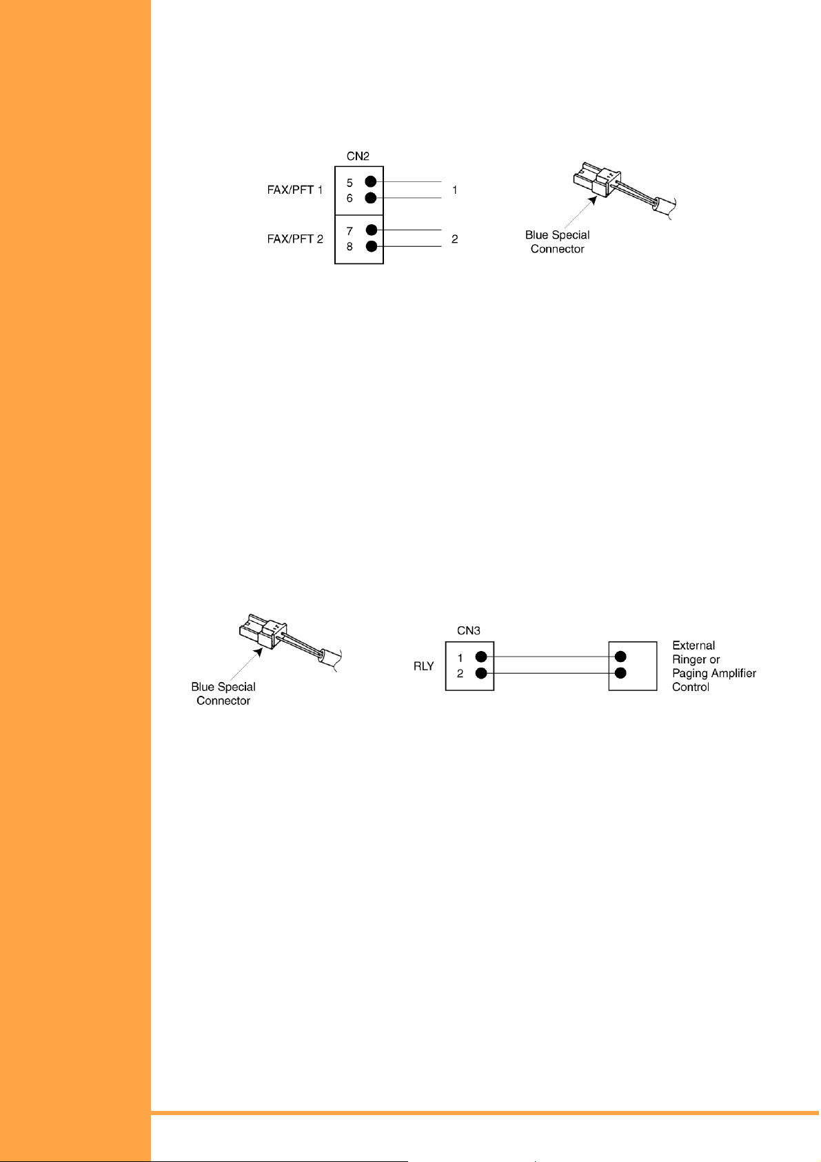
If not required as power fail telephone ports, the FAX/PFT ports of CN2 can be used to connect
other analogue equipment such as faxes and modems. These devices can make and receive
calls as per the normal operation, when the associated trunks are not in used by other users of
the system. Note t hat each device is dedicated to a trunk (CO1 or CO2) as indicated above. Any
activity by these devices will be shown as a busy trunk status on the handsets of other users on
the system.
Figure 2-17: Power Fail Telephone and Fax Connection
External Ringer and External Paging Control connection
The B614-B13 ETU supports the connection of an External Ringer, via CN3-RLY, which can
be used to activate a locally supplied loud sounding alarm. This alarm can be programmed
to sound while an incoming CO/PBX, DID or DIT call is ringing and is ideal for large or noisy
areas, or for the hearing impaired. The output of CN3 is a no-voltag e relay contac t opera tion
with the following specifications.
Cadence (Cycle): 1 second ON (closed)/2 seconds OFF (open)
Maximum Voltage: 24 Vdc
Maximum Current: 200 mA
Alternatively, CN3-RLY can be programmed to operate as an External Paging Amplifier
Controller. In this mode, the relay of CN3 will close when an external page is initiated and
will remain closed until the page is terminat ed. This no-voltage signal can be used to turn on
(and off) the locally supplied external paging amplifier. But not that the voltage and current
limits shown above will always apply!
Figure 2-18: External Ringer Connection
External Speaker Connection
The B614-B13 ETU provides one pre-amp level output for connection of an External Paging
System. This paging system would include as a minimum, a Line Isolation Unit, Audio
Amplifier and Speaker. As well as external paging, this speaker may also be sued as alert
upon incoming external calls.
Installation Manual
A6-506000-642-01
If On/Off control of the amplifier is required, Memory Block 001-0 must be set. Then when an
External Page is pe rfo rmed, th at co nt rol r el ay wi ll c lose pr ov idi ng a d r y ind ica t ion to t he amp lif ie r.
(Refer to External Ringer and External Paging Control connection.)
KSU Installation Page 35
• • •
Page 50

If a Paging Alert Tone is required to precede each External Paging message, Memory Block
002-3 must be set.
The paging equipment terminates onto the EXT.SPK connector of CN1 using a Special
Connector. If amplifier on/off control is required, this terminates onto the General Purpose
Relay connector (CN3-RLY), again using a Special Connector.
Connection of this equipment must be via a Line Isolation Unit with a Telecommunications
compliance label. The Baterford Electronics Model BE-104 is an example.
Figure 2-19: External Paging Connection
External Music-On-Hold (MOH)/Background Music (BGM) Source Connection
The B614-B13 ETU can be used to connect an external music source for use with the
Music-On-Hold and Background music facilities e.g. radio, CD player or tone source.
Connect two wires from the music source to the MOH/BGM connecti on of CN1 (using a Blue
Special connector). This is not polarity sensitive.
Page 36 KS U Installation
Installation Manual
• • •
A6-506000-642-01
Page 51
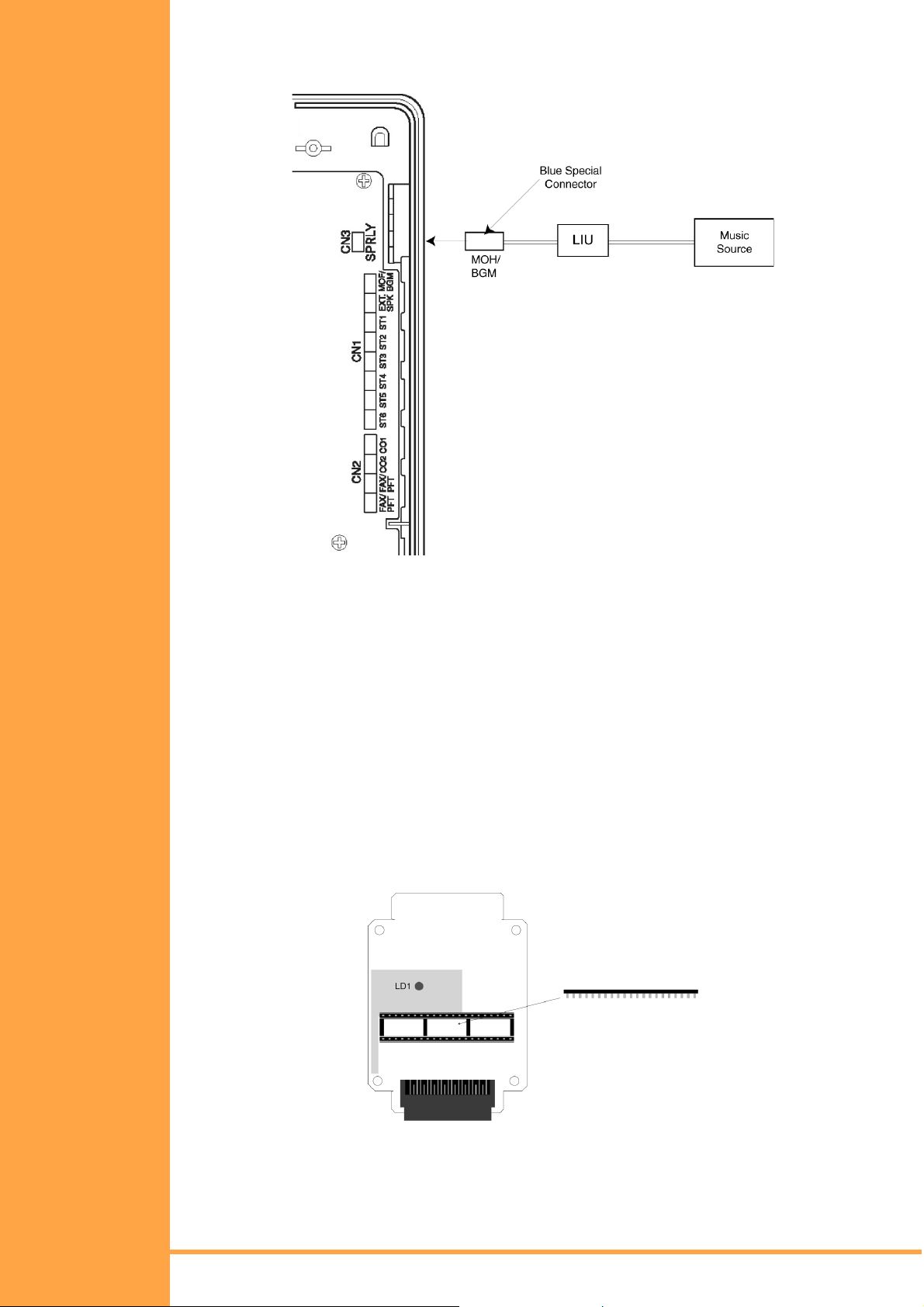
Adjust the music source to a suitable level by making an internal call, placing it on Hold and
listening to the music whilst adjusting the output level of the music source itself.
Figure 2-20: MOH/BGM Source Connection
External ROM Card
To upgrade the main system software of the Xen Alpha you will need an External ROM card
and an EPROM containing the new software. The ROM card can be used to upgrade many
systems and can be reused as new software versions are released by f itting a new EPROM.
Preparing the ROM Card:
1. Carefully remove the ROM card from its packaging, using a wrist strap connected to
protective earth to avoid static discharge.
2. Mount the new EPROM onto the ROM card into socket ICI.
! NOTE: Check for correct orientation of the EPROM and ensure that all pins are
properly aligned over the socket before firmly pushing in the EPROM.
Installation Manual
A6-506000-642-01
Figure 2-21: External ROM Card
KSU Installation Page 37
• • •
Page 52
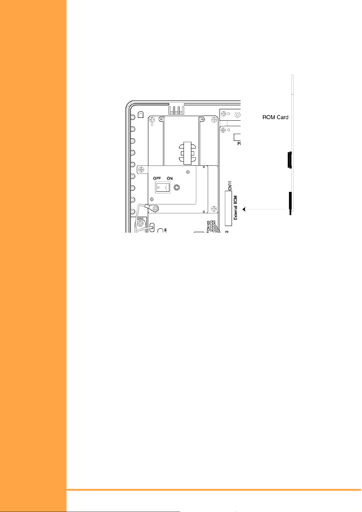
To upgrade a Xen Alpha system:
1. Use PC Programming, download and ‘save to disk’ the current syste m setup.
2. Switch the system OFF.
3. Remove the cover from the KSU.
4. Locate connector CN11 (marked External ROM) on the mainboard and plug the ROM
card into it.
Figure 2-22: Inserting the External ROM Card
5. Turn the system ON. LED LD1 on the ROM card and the LIVE LED on the mainboard
will light red. The ROM LED on the mainboard will fl ash red to i ndicat e that t he pr ogram
is in the process of being transferred.
6. Once the ROM LED has stopped flashing, turn the system OFF and remove the
ROM card.
7. Replace the KSU cover.
8. Turn the system ON.
9. Using PC Programming, upload the saved system setup.
Page 38 KS U Installation
Installation Manual
• • •
A6-506000-642-01
Page 53
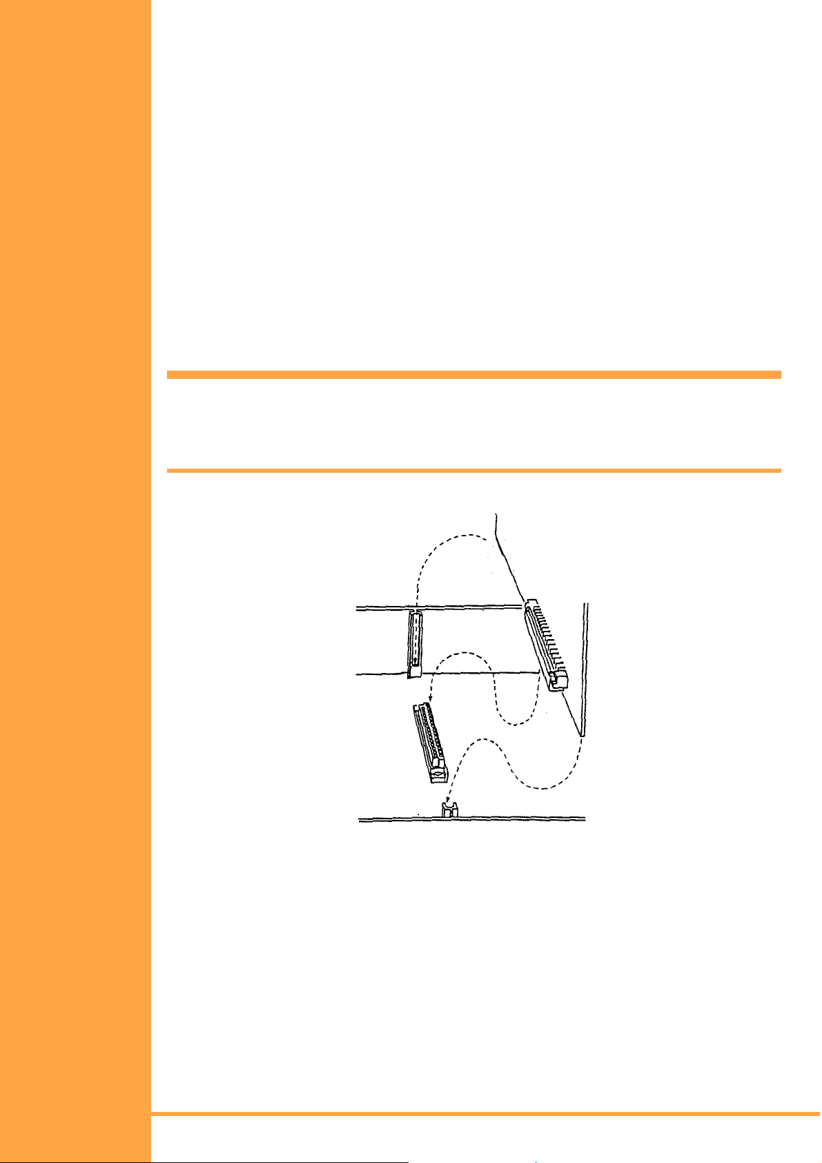
S
ECTION
I
NSTALLING AN
E
LECTRONIC
T
ELEPHONE UNIT
ETU
4
General Information
Installation Precautions
Before installation of the KTUs, observe the below precautions.
1. To prevent accidental damage to equipment, the power must be OFF during installation
and maintenance.
2. The KTUs used in this system make extensive use of CMOS technology. CMOS
technology is very susceptible to static; therefore extreme care must be taken to avoid
static discharge when handling KTUs.
KTU Inst allation
Be sure to mount the KTUs in the correct position inside the KSU. Make any connections
and switch settings on the KTUs before inserting them in the KSU. Also refer to Fi gure 2-23::
Installing a Vertically Mounted KTU, Pg 39.)
CAUTION
When a KTU is instal led or removed, ens ure that the power swi tc h of
the KSU is in the OFF position.
Installation Manual
A6-506000-642-01
Figure 2-23: Installing a Vertically Mounted KTU
KSU Installation Page 39
• • •
Page 54
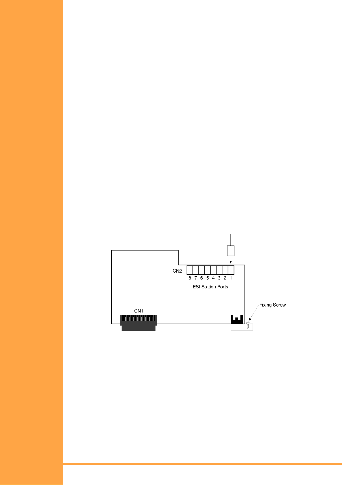
Interface ETUs
ESI(8)-B13 ETU
The ESI ETU is an interface for Multiline Telephones and SLT Adapters and allows a further
eight such devices to be connected to the system. One ESI(8)-B13 ETU can be installed in
the system, providing a total of 14 Multiline telephones. These ESI ports are arranged as
follows:
Mainboard (Built-in ESI) ! Extension Ports 01 to 06
ESI(8)-B13 ETU (CN4) ! Extension Ports 07 to 14
To install the ESI(8)-B13 ETU:
1. Ensure that the system is turned OFF.
2. Remove the cover from the KSU.
3. Carefully remove the ETU from its packaging, using a wrist strap connected to the
frame ground on the KSU to avoid static discharge.
4. Locate connector CN4 (marked ESI) on the mainboard and slide the ETU between the
posts. Press the ETU down firmly to lock into place.
5. Using a philips head screwdriver, secure the ETU to the KSU by tightening the screw
captive in the metal bracket on the ETU.
6. Run the ESI cabling from the ETU to t he external MDF. A single twisted-pair is required
for each connection and this is not polarity sensitive. Crimp the special connector
supplied to each cable pair.
7. Replace the KSU cover.
8. Turn the system ON.
9. Program the system as required, although the additional ports are automatically
assigned default values.
Figure 2-24: ESI(8)-B13 ETU
SLI(2)-B13 ETU
The SLI ETU is an interface for two Single Line telephones or other analogue devices such
as cordless telephones, facsimiles, modems and answering machines. One SLI(2)-B13
ETU can be installed in the system, taking the total number of extension ports to 16. These
ports are numbered as follows:
Mainboard (Built-in ESI) ! Extension Ports 01
ESI(8)-B13 ETU (CN4) ! Extension Ports 07
SLI(2)-B13 ETU (CN13) ! Extension Ports 15
"
"
"
06
14
16
To install the SLI(2)-B13 ETU:
1. Ensure that the system is turned OFF.
2. Remove the cover from the KSU.
Page 40 KS U Installation
Installation Manual
• • •
A6-506000-642-01
Page 55

3. Carefully remove the ETU from its packaging, using a wrist strap connected to the
frame ground on the KSU to avoid static discharge.
4. Using a philips head screwdriver, secure the ETU to the KSU by tightening the screw
captive in the metal bracket on the ETU.
5. Run the SLI cabling from the ETU to the external MDF. A single twisted-pair is required
for each connection, this is not polarity sensitive. Crimp the special connector supplied
to each cable pair.
6. Replace the KSU cover.
7. Turn the system ON.
8. Program the system as required, although the additional ports are automatically
assigned default values.
Figure 2-25: SLI(2)-B13 ET U
COI(2)-B13 ETU
The COI ETU is an interface for two analogue Central Office Trunks (exchange lines) and
contains circuitry for ring detection, holding, dialling and control functions. Each Loop Start
trunk may be programmed as either DTMF or Decadic dialling. Two COI(2)-B13 ETUs can
be installed in the system, providing a total of 6 CO/PBX trunks. These ports are arranged
as follows:
Mainboard (Built-in COI)! Trunk Ports 01 to 02
COI(2)-B13 ETU (CN14)! Trunk Ports 03 to 04
COI(2)-B13 ETU (CN16)! Trunk Ports 05 to 06
To install the COI(2)-B13 ETU:
1. Ensure that the system is turned OFF.
2. Remove the cover from the KSU.
3. Carefully remove the ETU from its packaging, using a wrist strap connected to the
frame ground on the KSU to avoid static discharge.
4. Using a philips head screwdriver, secure the ETU to the KSU by tightening the screw
captive in the metal bracket on the ETU.
5. Run the COI cabling from the ETU to the external MDF. A single twisted-pair is requir ed
for each connection, this is not polarity sensitive. Crimp the special connector supplied
to each cable pair.
Installation Manual
A6-506000-642-01
6. Replace the KSU cover.
7. Turn the system ON.
KSU Installation Page 41
• • •
Page 56
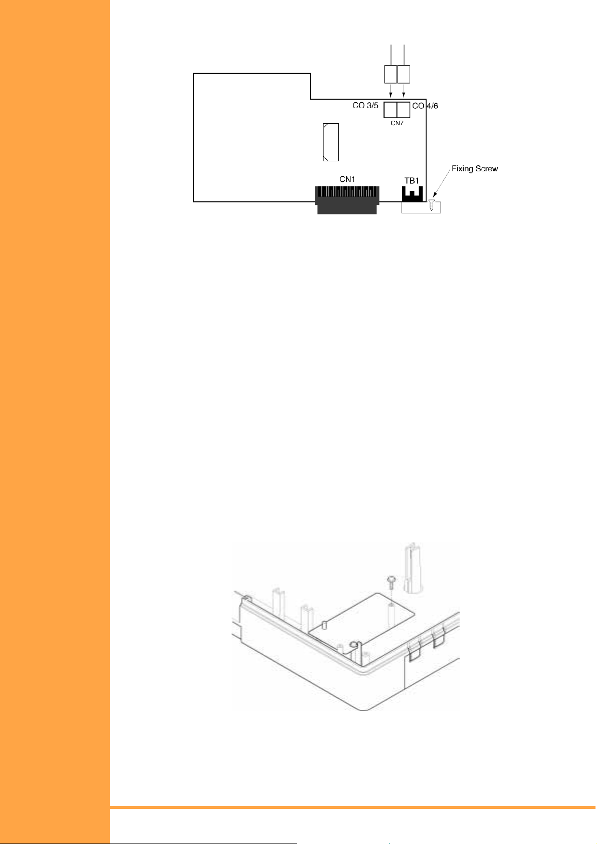
Program the system as required, although the additional ports are automatically assigned
default values.
Figure 2-26: COI(2)-B13 ETU
CID(2)-B13 Unit
The CID Unit provides analogue COI trunks with incoming Caller ID indication. Three
CID(2)-B13 Units can be installed in the system, one on the mainboard and one on each of
the COI(2)-B13 ETUs, providing each of t he 6 analogue COI t runks wi th Caller ID indi cation .
This arrangement is indicated as follows:
Mainboard (Built-in COI) ! Trunk Ports 01 to 02
COI(2)-B13 ETU (CN14) ! Trunk Ports 03 to 04
COI(2)-B13 ETU (CN16) ! Trunk Ports 05 to 06
To install the CID(2)-B13 ETU:
1. Ensure that the system is turned OFF.
2. Remove the cover from the KSU.
3. Carefully remove the Unit from its packaging, using a wrist strap connected to the
frame ground on the KSU to avoid static discharge.
To install the COI Ports 1 to 2:
4. Locate connector CN18 (marked CID) on the mainboard, then position the CID Unit
over it making sure that the small hole in the CID Unit is aligned with the post on the
KSU. Press the unit down firmly to lock it into place and secure with the two screws
supplied using a philips head screwdriver.
Figure 2-27: Mounting the CID(2)-B13 Unit onto the Mainboard
Page 42 KS U Installation
Installation Manual
• • •
A6-506000-642-01
Page 57
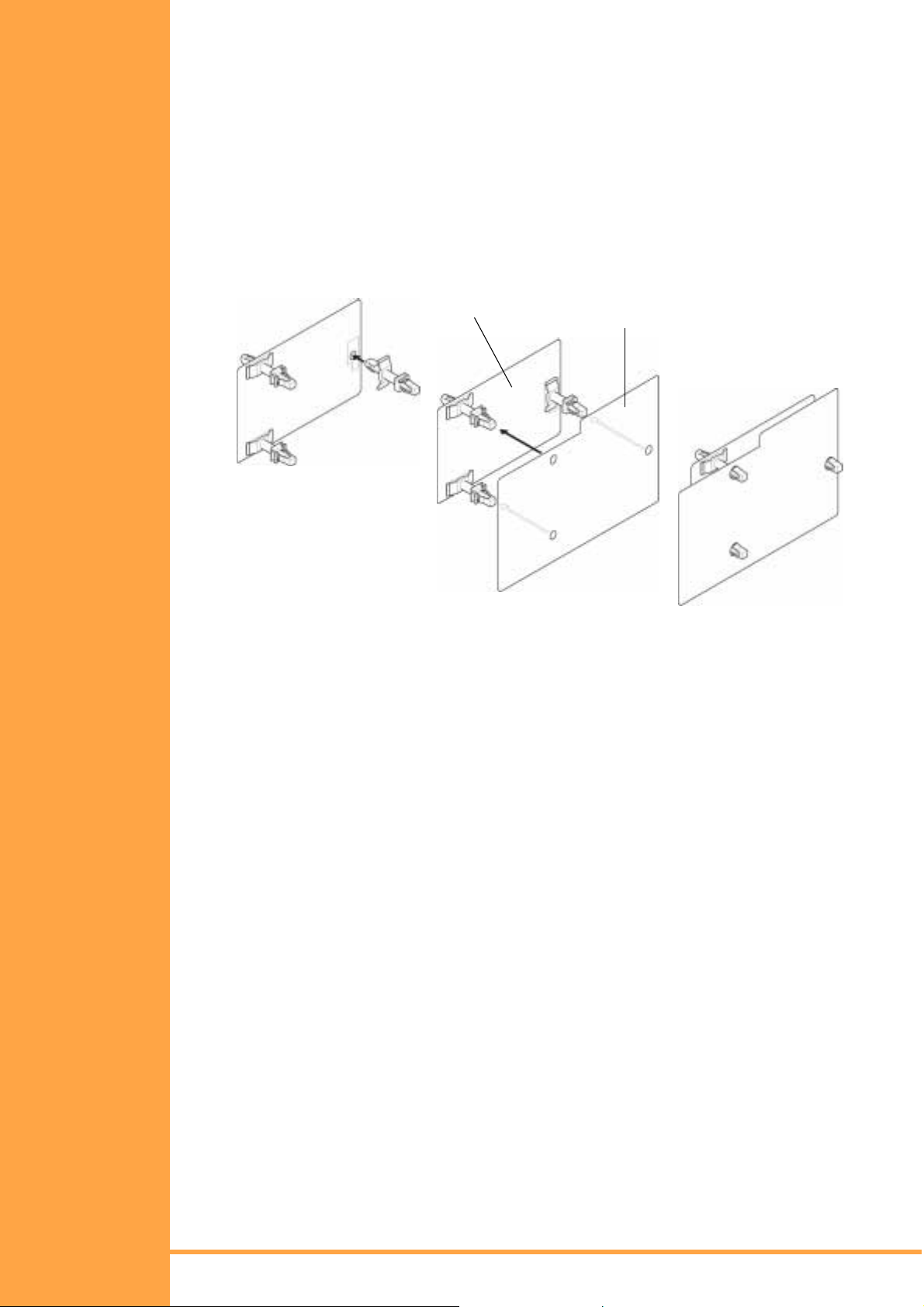
To install for COI Ports 3"4 or 5"6:
1. If the COI(2)-B13 ETU is already installed, remove its screw using a philips head
screwdriver and then carefully remove the board from its slot.
2. Attach the three plastic stand-of fs supplied to the CID Unit by pressi ng the large fla nged
end into the hole in the CID Unit. Place these onto the side of the Unit where connector
CN1 is located.
3. Locate connector CN2 (marked CID) on the COI ETU, then position the CID Uni t over it
making sure that the stand-offs on the CID Unit are aligned with the holes in the COI
ETU. Press the two boards together firmly to lock into place each standoff and the
mating connectors.
4. Reinstall the COI ETU into the KSU. (Refer to COI(2)-B13 ETU, Pg 41.)
Figure 2-28: Mounting the CID(2)-B13 Unit onto the COI(2)-B13 ETU
5. Replace the KSU cover.
6. Turn the system ON.
BRT(1)-B13 ETU
CID(2)-B13 UNIT
COI(2)-B13 ETU
The BRT ETU provides an interface for one ETSI compliant, Point-to-Multipoint, Basic Rate
ISDN service. This digital service supplies two 64 kbps channels, which can each carry a
voice call. Therefore providing the system with two trunks. Two BRT(1)-B13 ETUs can be
installed in the system, providing a total of 6 CO/PBX trunks. These ports are arranged
as follows:
Mainboard (Built-in COI) ! Trunk Ports 01 to 02
BRT(1)-B13 ETU (CN15) ! Trunk Ports 03 to 04
BRT(1)-B13 ETU (CN17) ! Trunk Ports 05 to 06
To install the BRT(1)-B13 ETU:
1. Ensure that the system is turned OFF.
2. Remove the cover from the KSU.
3. Carefully remove the ETU from its packaging, using a wrist strap connected tot he
frame ground on the KSU to avoid static discharge.
4. Locate connector CN15 or CN17 (marked BRT) on the mainboard and slide the ETU
between the posts. Press the ETU down firmly to lock into place.
5. Using a philips head screwdriver, secure the ETU to the KSU by tightening the screw
captive in the metal bracket on the ETU.
Installation Manual
A6-506000-642-01
KSU Installation Page 43
• • •
Page 58

6. Run the BRT cable f rom the ETU t o t he ext ernal NT-1 (t he int erf ace box in stall ed b y the
ISDN service provider). A twin twisted-pair cable is required, terminated at each end
with an RY-45 plug in a 1-1 configuration. CAT-5 or similar cable is recommended.
(Refer to Figure 2-30:: BRT(1)-B13 ETU Connection Cable, Pg 44.)
7. Replace the KSU cover.
8. Turn the system ON.
9. Program the system as required, although the additional ports are automatically
assigned default values.
Figure 2-29: BRT(1)-B13 ETU
Figure 2-30: BRT(1)-B13 ETU Connection Cable
Optional ETUs
PBR-B13 ETU
The Push Button Receiver (PBR) ETU detects and translates DTMF dialling tones
generated by single line telephones, faxes, modems etc., connected to the system via the
SLI(2)-B13 ETU, APR-UA Unit or the FAX Port. One PBR-B13 ETU can be installed in the
system, providing 4 PBR circuits.
To Install the PBR-B13 ETU:
1. Ensure that the system is turned OFF.
2. Remove the cover from the KSU.
3. Carefully remove the ETU from its packaging, using a wrist strap connected tot he
frame ground on the KSU to avoid static discharge.
4. Attach the plastic stand-off (supplied) to the PBR ETU by pressing the large flanged
end into the hole in the lower left of the ETU. Place this onto the side of the ETU where
connector CN1 is located.
5. Locate connector CN9 (marked PBR) on the mainboard, then position the PBR ETU
over it making sure that the stand-off on the ETU and the post on the KSU are both
properly aligned. Press the ETU down firmly to lock into place the stand-off and the
mating connectors.
6. Secure the PBR ETU with the screw supplied using a philips head screwd ri ver.
7. Replace the KSU cover.
Page 44 KS U Installation
Installation Manual
• • •
A6-506000-642-01
Page 59

8. Turn the system ON.
PBR-B13 ETU
Plastic Stand-off
Figure 2-31: PBR-B13 ETU
MIF-B13 ETU
The MIF-B13 ETU provides one RS-232 port and additional memory to support the PC
Programming and Station Message Detail Recording (SMDR) facilities. One PBR-B13 ETU
can be installed in the system.
To install the MIF-B13 ETU:
1. Ensure that the system is turned OFF.
2. Remove the cover from the KSU.
3. Remove the ground place (located at the bottom of the KSU) by removing its crew
located inside the KSU.
Figure 2-32: Removing the Ground Plate
4. Place the green grounding wire on top of the DB-9 plate (supplied) and tighten with the
original screw.
Installation Manual
A6-506000-642-01
Figure 2-33: Mounting the DB-9 Plate
KSU Installation Page 45
• • •
Page 60

5. Carefully remove the ETU from its packaging, using a wrist strap connected tot he
frame ground on the KSU to avoid static discharge.
6. Locate connector CN12 (marked MIF) on the mainboard and slide the ETU between
the posts. Press the ETU down firmly to lock into place.
7. Using a philips head screwdriver, secure the ETU to the KSU by tightening the screw
captive in the metal bracket on the ETU.
8. Plug the 8-way connector on the end of the DB-9 CABLE into CN2 on the MIF ETU.
Plug the mail DB-9 end of the serial cable conne cting t o your PC or Printe r into t his DB9 socket on the KSU.
Figure 2-34: Connecting the DB-9 Cable
9. Replace the KSU cover.
10. Turn the system ON.
11. Program the system as required.
RS-232C Interface Specifications:
Baud Rate: SMDR – 1200, 2400, 4800*, 9600 bps
PS Programming – 19200 bps (fixed)
Data Length: 8 bits
Stop Bits: 1*, 2 bits
Parity: None
Flow Control: XON/XOFF
(* = Default Setting)
RS-232C Cable Requirements:
Straight RS-232C serial cable terminated with male DB-9 connector at one end. The other
end of the cable will be terminated to suit the connected equipment (i .e. printer, PC, etc.).
Figure 2-35: MIF-B13 ETU
Page 46 KS U Installation
Installation Manual
• • •
A6-506000-642-01
Page 61

DPH-B13 ETU
The Door Phone (DPH) ETU provides connection for two Door Phone units and two Door
Lock Release devices. Use only the NEC DP-D-1D Door Phone Unit. A suitable third-party
door lock release device must be locally supplied. One DPH-B13 ETU can be installed in
the system.
To install the DPH-B13 ETU:
1. Ensure that the system is turned OFF.
2. Remove the cover from the KSU.
3. Carefully remove the ETU from its packaging, using a wrist strap connected to the
frame ground on the KSU to avoid static discharge.
4. Locate connector CN5 (marked DPH) on the mainboard and slide the ETU between
the posts.
5. Using a philips head screwdriver, secure the ETU to the KSU by tightening the screw
captive in the metal bracket on the ETU.
6. Run the cabling for the door phones and door lock releases from the ETU to the
external MDF. A single pair is required for each connection, and this is not polarity
sensitive.Crimp the special connector suppli ed to each cable pair.
7. Replace the KSU cover.
8. Turn the system ON.
9. Program the system as required.
Figure 2-36: DHP-B13 ETU
Installation Manual
A6-506000-642-01
KSU Installation Page 47
• • •
Page 62

Door Phones
Switches SW1, SW2 and RV1 allow the volume l evels bet ween the door phone un its and t he
KSU to be adjusted. Adjust these switches as required to achieve optimal door phone
performance. (Refer to Table 2-2: DPH-B13 ETU Switch Settings, Pg 48.)
Table 2-2 DPH-B13 ETU Switch Settings
Function Reference Default Settings
Volume Adjustment:
Telephone to Doorphone
Volume Adjustment:
Telephone to Doorphone
Balance Adjustment:
Between DP1 & DP2
SW1 NORMAL
SW2 NORMAL
RV1
This adjustment effects DP1 & DP2.
NORMAL:Normal Volume
LOUD: Increased Volume
This adjustment effects DP1 & DP2.
NORMAL:Normal Volume
LOUD: Increased Volume
Turn RV1 to adjust the Sidetone of
the doorphone call. Lower the
Sidetone if howling occurs in either
the telephone or doorphone.
When the Door Phone button is pressed, one of two tones is produced at the assigned
telephones (ports 01 and 02 as default).
Connections:
Wiring to each Door Phone requires a single-pair cable, to a maximum Loop Resistance of
20 Ω. Connections DPH1 and DPH2 are not polarity sensitive.
Page 48 KS U Installation
Installation Manual
• • •
A6-506000-642-01
Page 63

Door Lock Release
While on a Door Phone call, the telephone user can enter an Access Code to operate the
associated Door Lock Release momentarily so that the caller can enter the door.
Connections
Connection between terminals DPR1, DPR2 and the door lock device is via a single pair
cable, not polarity sensitive. A dry contact closure is provided to the external device.
Connection of door lock release equipment must be via a Line Isolation Unit with a
Telecommunications compliance label. The Batesford Electronics Model BE-104 is an
example.
TRF-B13 ETU
The Trunk Transfer (TRF) ETU allows an analogue trunk to be used as the incoming or
outgoing trunk in a Call Forward External operation. Note that the outgoing trunk must be
provided with Line Reversal on Answer by the service provider. The TRF ETU is not
required however, if both trunks are ISDN. One TRF-B13 ETU can be installed in the
system, providing one trunk transfer ci rcuit.
To install the TRF-B13 ETU:
1. Ensure hat the system is turned OFF.
2. Remove the cover from the KSU.
3. Carefully remove the ETU from its packaging, using a wrist strap connected to the
frame ground on the KSU to avoid static discharge.
4. Locate connector CN8 (marked TRF) on the mainboard and slide the ETU between the
posts. Press the ETU down firmly to lock into place.
5. Replace the KSU cover.
6. Turn the system ON.
7. Program the system as required.
Figure 2-37: TRF-B13 ETU
Trunk Transfer Speech Volume Adjustment
Installation Manual
A6-506000-642-01
Refer to Table 2-3: TRF-B13 ETU Switch Settings, Pg 50, and Table 2-4: CO/PBX Line Loss
Compensation, Pg 50 if speech volume during a transferred call is too low.
When operating with Auto Level Control and Voice Switches OFF, take note of the following
points during transmission tests. If satisfactory settings cannot be achieved under the
following conditions, operate with the Voice Switch ON.
KSU Installation Page 49
• • •
Page 64
1. If the incoming trunk receiving volume is too low, change the G11/G12 switch setting to
one level higher.
2. If the transfer destinati on trunk r eceivi ng volu me is too low, change the G21/G22 switch
setting to one level higher.
3. If the incoming trunk receiving signal contains a ‘booming’ noise, change the G11/G12
switch setting to one level lower.
4. If the transfer destination trunk receiving signal contains a ‘booming’ noise, change the
G21/G22 switch setting to one level lower.
CAUTION
1. Depending on line conditions, speech levels may decrease during trunk transfer.
2. Hold tones may become distorted when the Voice Switch is ON.
Table 2-3 TRF-B13 ETU Switch Settings
Item Switch Default Setting
ON: Transmitter/receiver switching as in a
transceiver.
Vo ice Switch
Usage
Speech
Volume
Control for
Trunk
Transfer
Level
*Use same setting for destina tion trunk
Voic e Sw itch
(VSW)
Incoming Trun k
Receiving
Volume Switch
Outgoing Trunk
Trans mit Volume
Switch
ON
G11:OFF
G12:OFF
G21:OFF
G22:OFF
receiving volume switch and incoming
trunk receiving volume switch .
*If speech volume cannot be adjusted
using the procedure below, set switch
to ON.
• Refer to Table
Line Loss Compensation, Pg 50
details.
* Adjust transfer destination trunk and
incoming trunk speech volume during a
trunk transferred call.
• Set receiving volume level according
to line loss (in dBm) in the circuit up to
the exchange line destination point.
Table 2-4 CO/PBX Line Loss Compensation
Incoming Trunk
CO/PBX Line
Resistance
Compensation
Level
Receive Volume
Table 2-4: CO/PBX
for
Outgoing Trunk
Transmit Volume
G11 G12 G21 G22
"
4
3
2
1
Page 50 KS U Installation
1281
(9.0 " 14.0 dBm)
"
911
(6.0 " 9.0 dBm)
"
551
(3.0 " 6.0 dBm)
<550
(<3.0 dBm)
1880
1280
910
Ω
Ω
Ω
Ω
+12 dBm ONONONON
+9 dBm ON OFF ON OFF
+6 dBm OFF ON OFF ON
+3 dBm OFF OFF OFF OFF
Installation Manual
• • •
A6-506000-642-01
Page 65
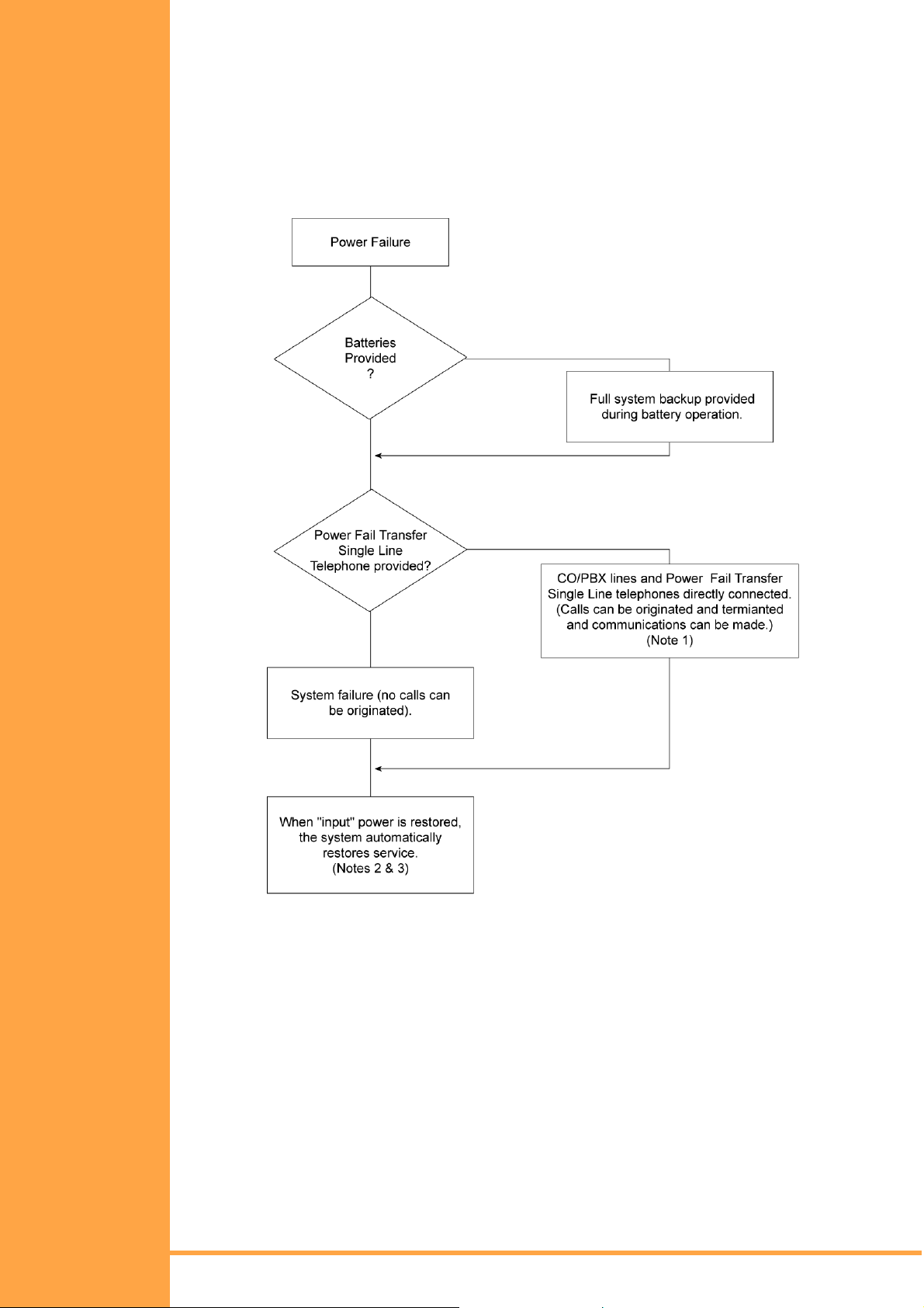
Power Failure Backup
Operation in the Event of a Power Failure
In the event of a power failure, the optional built-in batteries or external batteries (locally
provided) provide full backup of the service of the system for a period dependent on the
system configuration and service conditions. Two Power Fail Transfer (PFT) Single Line
telephone Interface Circuit are built into the KSU. The KSU connects each Single Line
Telephone directly to CO/PBX line (01 ans 02) to allow origination and termination of calls.
(Refer to Figure 2-38:: Power Failure Backup Flowch art, Pg 51 .)
Installation Manual
A6-506000-642-01
Figure 2-38: Power Failure Backup Flowchart
! Note 1: All calls in progress are interrupted when switch over is made to connect the
Power Fail Transfer Single Line telephones directly to the CO/PBX Line 1.
This occurs after backup batteries have expi red.
! Note 2: If the power switch of the KSU is in the OFF position, the system will not
automatically restart service.
! Note 3: When power is restored, calls in progress on the Power Fail telephones will
not be interrupted.
KSU Installation Page 51
• • •
Page 66

Operation When Input Power is Restored
When input power is restored, the system automatical ly resets and restores service.
Single Line Telephone for Power Fail Transfer
A Single Line telephone can be used as a Power Fail Transfer telephone. (Refer to Power
Fail telephone and Fax connection for details.)
Operating Procedure
To use the Single Line telephone for power fail transfer during a power failure, proceed
as follows:
Originating:
1. Lift the handset. (Ensure that dial done is heard.)
2. Dial the desired number.
3. Talk.
Receiving:
1. Receive ringing tone.
2. Lift the handset and answer.
S
ECTION
C
C
ONNECTIONS
5
ABLE
! Note: The Single Line telephone, designated for Power Fail Transfer, must match
the dialling type of the corresponding CO/PBX line (10 pps, 20 pps or DTMF)
where it is connected.
General Information
Connection Requirements
The KSU is connected with each of the Multiline Terminals, Single Line telephones, optional
equipment and analogue trunks by a separate twisted-pair cable through the MDF. ISDN
connection requires two twisted-pair cables. (Refer to Chapter 2 for details.)
Cabling Precautions
When selecting cables and the MDF, future expansion or assignment changes should be
given due consideration. Avo id running cables in the following places:
! A place exposed to wind or rain.
! A place near heat radiating equipment or where the quality of PVC covering could be
affected by gases and chemicals.
! An unstable place subject to vibration.
! Close proximity to computers or radio frequency generating equipment.
Page 52 KS U Installation
Installation Manual
• • •
A6-506000-642-01
Page 67

Terminating Cables to Special Connectors
When installing a B614-B13, KSU, ESI(8)-B13 ETU, COI(2)-B13 ETU, DPH-B13 ETU or
SLI(2)-B13 ETU, the cables must be terminated to the connectors provided in the KTU
packing box. The following instructions explain this procedure.
1. Cut the two cables the same length and insert them into the connector. Ensure that
each cable has been inserted all the way tot he end of the cover. (Ref er to Figure 2-39::
Attaching the Cables to the Connector, Pg 53.)
Adapter Cable
Core Diameter Insulation Diameter
ICT Cable
*Remove insulation from wire before inserting into connector.
Figure 2-39: Attaching the Cables to the Connector
0.40 mm 0.66 mm
0.50 mm 0.80 mm
0.65 mm * 1.20 mm
2. Lightly hold the connector with the pliers. In this case, make sure that the crimping
portion is held between the lower portion of the jaws of the pli ers. (Refer to Fig ure 2-40::
Holding the Connector with the Pliers, Pg 53.)
Figure 2-40: Holding the Connector with the Pliers
3. Squeeze the pliers to crimp the cables. If the cover is loose, press the cover again with
the pliers. Be careful when squeezing the handles of the pliers as excessive pressure
may cause damage to the connectors.
4. a) After crimping the leads into the special connectors, insert them into the
appropriate socket in the KSU, pushing firmly until the connector snaps securely
into position.
b) To di sconnect the plug from the soc ket, grasp i t firmly using a pair of pliers and pu ll
while holding the unit in place. Do not pull on the wires directly.
Installation Manual
A6-506000-642-01
c) Do not reuse the plugs once they have been clinched as this may result in a
poor connection.
KSU Installation Page 53
• • •
Page 68
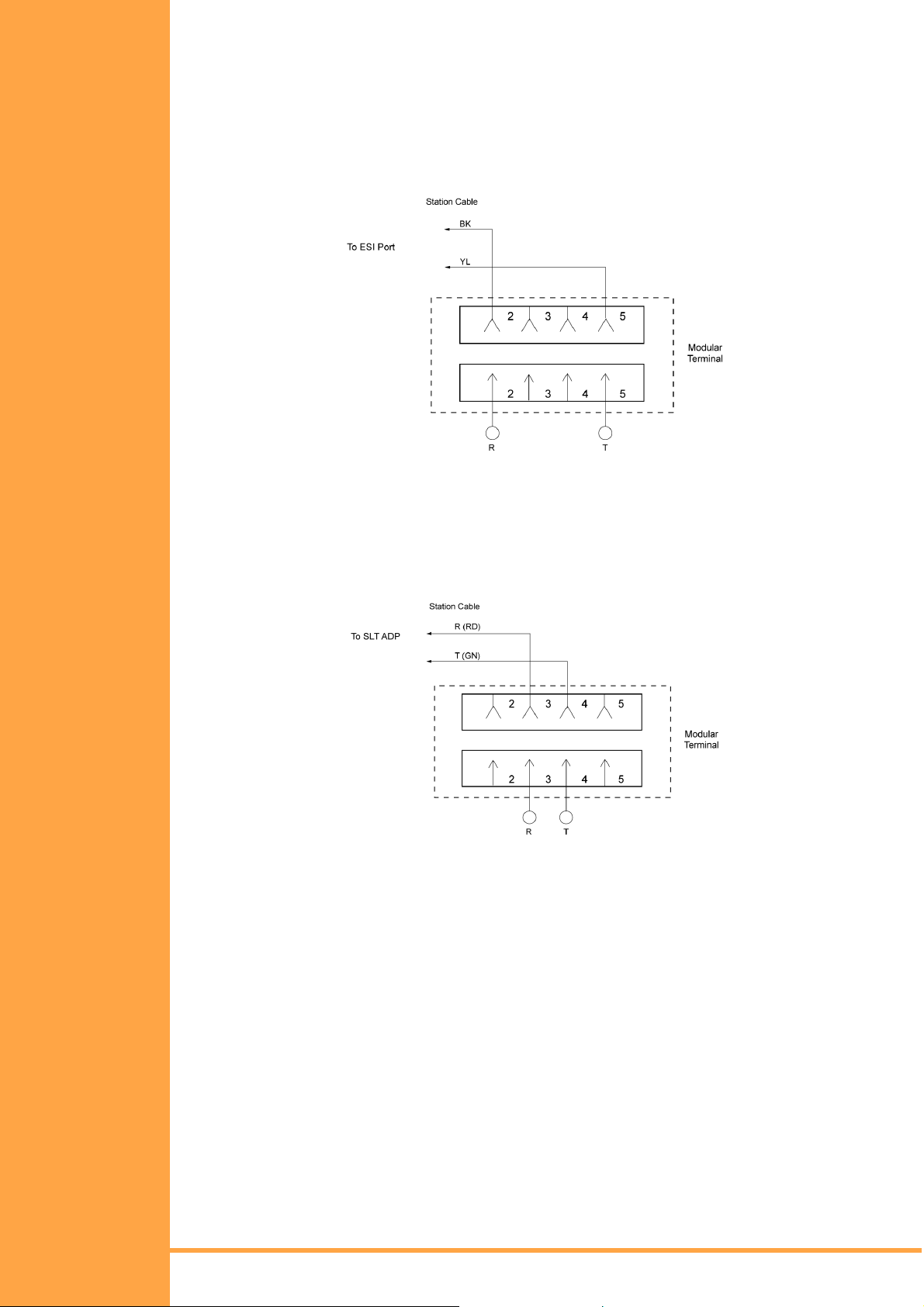
Wiring to th e KS U
Multiline Telephone Connection
When connecting Multiline Terminals to the MDF, indi vidually twisted 1-pair cabling must be
used. (Refer to F igure 2-41:: Multiline Terminal and SLT Adapter Connection, Pg 54.)
! Note: Polarity is not critical as the Multiline Terminals are not polarity conscious.
Figure 2-41: Multiline Terminal and SLT Adapter Connection
Single Line Telephone Connection
DTMF or DP dialling and Single Line Telephones can be used to dial within the system.
One-pair cabling is required, it is recommended that twisted pair cabling be used. (Refer to
Figure 2-42:: Single Line Telephone Connection, Pg 54.)
Figure 2-42: Single Line Telephone Connection
Outside Lines
CO/PBX lines are connected to this system using twisted pair wiring to cross-connect the
lines from the RJ11 termination block to the system.
Do not use half-tapping or parallel connections on outside lines connected to the system.
Page 54 KS U Installation
Installation Manual
• • •
A6-506000-642-01
Page 69
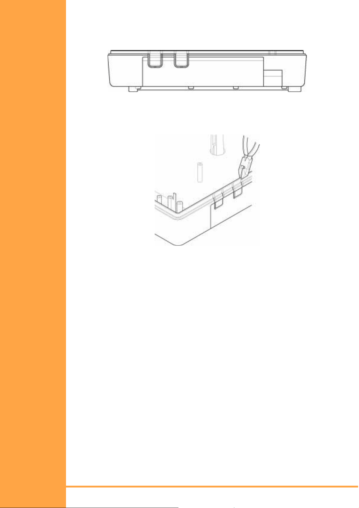
KSU Cable Routing
All cabling should exit the KSU through the knockout panels on the right hand side. Two
knockout panels are provided.
Figure 2-43: KSU Cabling Knockouts
Remove one or both of these knockouts as required, usi ng side cutters or other suitable t ool,
to cut the tabs at the top of the knockout. Once the top is free, move the knockout back and
forth until the tab at the bottom breaks free. Remove any burrs using a sharp knife.
Figure 2-44: Removing the Knockout Panels in the KSU
Run the cabling from each ETU neatly around the perimeter of the mainboard against the
side of the case and exit from the removed knockout(s). Secure cables to side of KSU with
the self adhesive cable tie mounts and cable ties suppl ied (quantity 2).
Installation Manual
A6-506000-642-01
KSU Installation Page 55
• • •
Page 70

This page is intentionally blank.
Page 56 KSU Installation
Installation Manual
• • •
A6-506000-642-01
Page 71
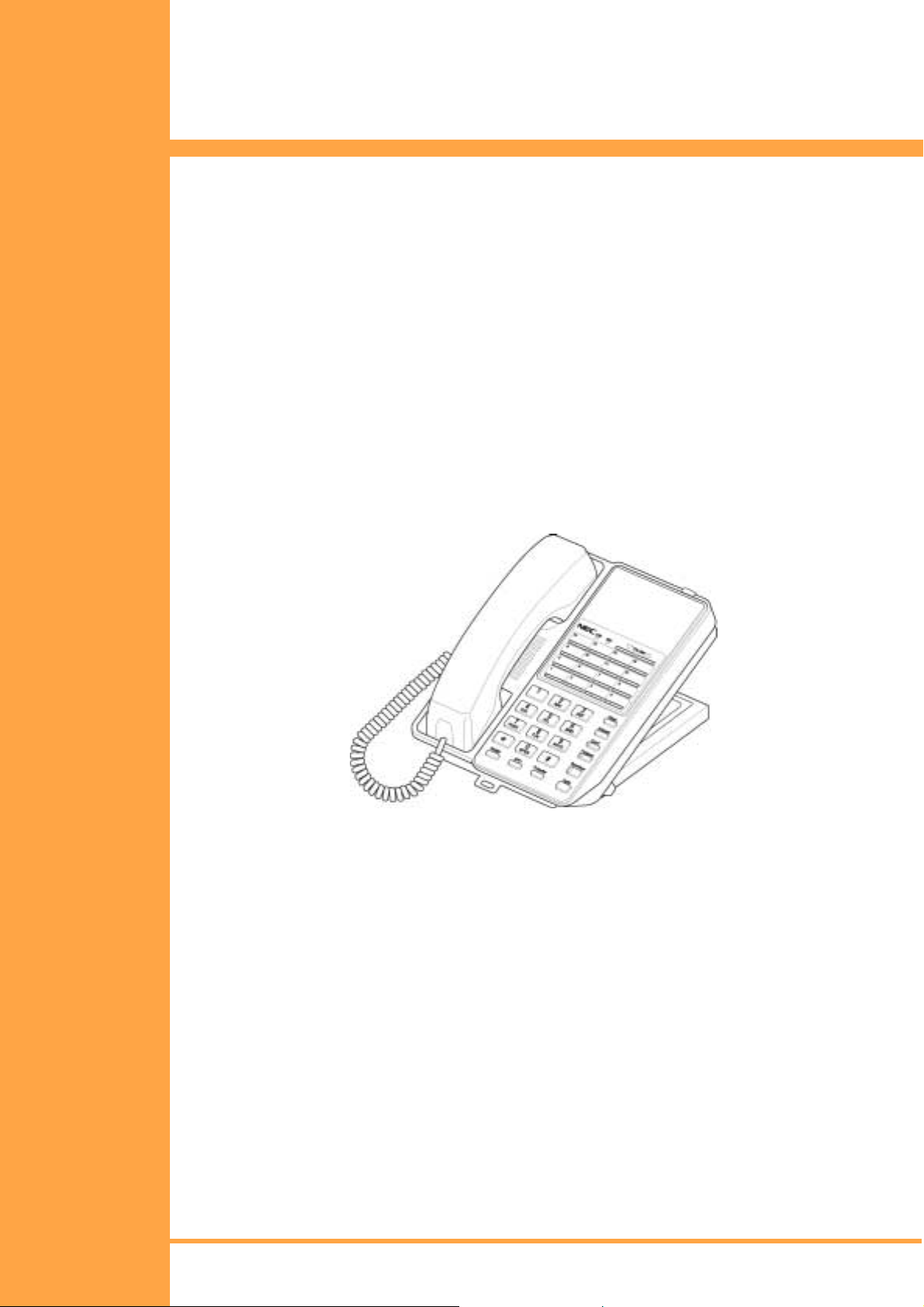
C
HAPTER
3
Installing DTB-Type Multiline
Terminals
Xen Alpha Release 1.0
S
ECTION
G
ENERAL
I
NFORMATION
S
ECTION
M
ULTILINE
T
ERMINALS
1
The Xen Alpha system provides a choice of two different DTB-Type Multiline telephones.
This chapter describes each terminal and provides applicable installation instructions.
2
DTB-16-1A (WH)/(BK) TEL
This digital non-display Multiline Terminal is equipped with eight programmable line keys
(each with a two-colour LED), a built-in speakerphone, headset jack, a large LED to indi cate
incoming calls and messages, and compatibility with ADA-UA, APR-UA, CTA-UA, and HFUUA Units .
A maximum of 119 DTU-8-1 (WH) TELs can be installed in the Xen Master system and a
maximum of 31 in the Xen Axis system.
Installation Manual
A6-506000-642-01
Figure 3-1: DTB-16-1A (WH)/(BK) TEL Multiline Telephone
Installing DTB Type Multiline Monitors Page 59
• • •
Page 72
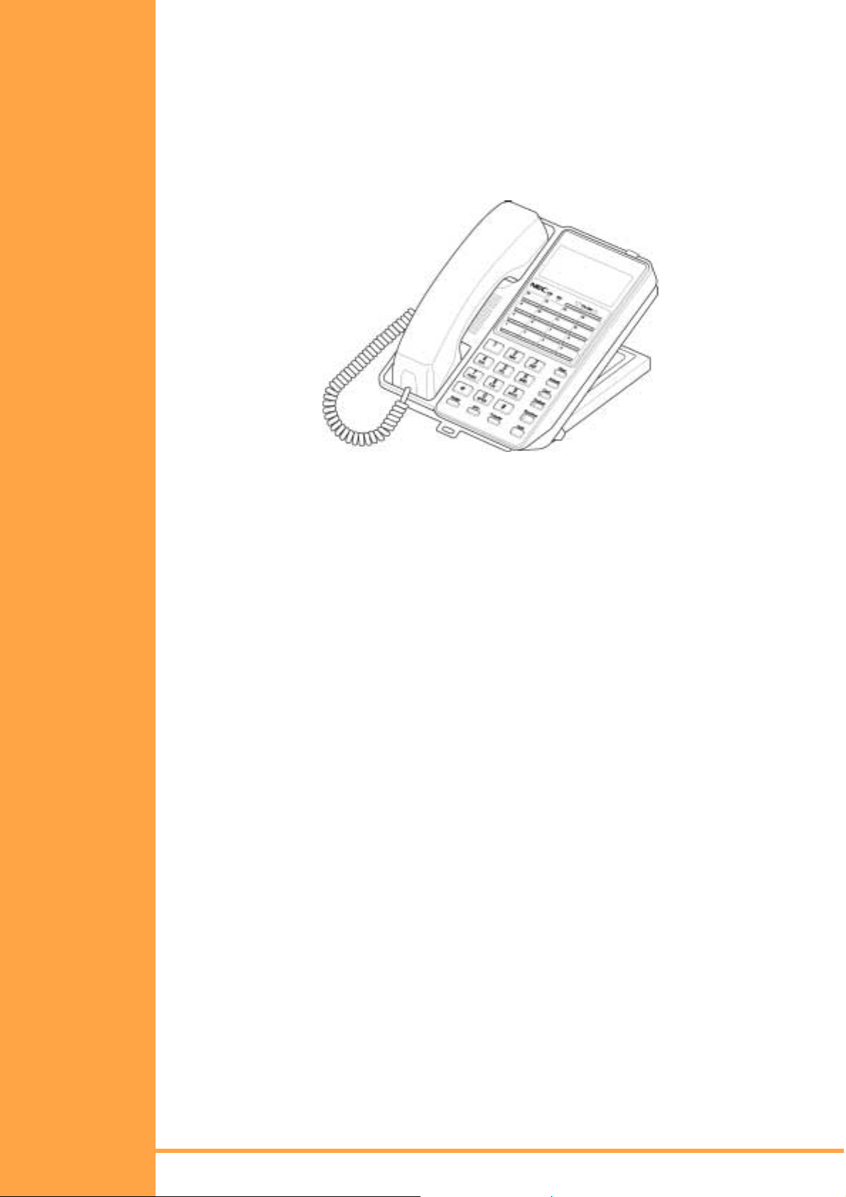
DTB-16D-1A (WH)/(BK) TEL
This digital Multiline Terminal has eight programmable line keys (each with the two-colour
LED), four softkeys, a built-in speakerphone, headset jack, a Large LED to indicate
incoming calls and messages, and compatibility with ADA-UA, APR-UA, CTA-UA and HFUUA Units .
This terminal is also equipped with a 3-line, 24-character, adjustable Liquid Crystal
Display (LCD).
Figure 3-2: DTB-16D-1A (WH)/(BK) TEL Multiline Telephone
Page 60 Installing DTB Type Multiline Monitors
Installation Manual
• • •
A6-506000-642-01
Page 73
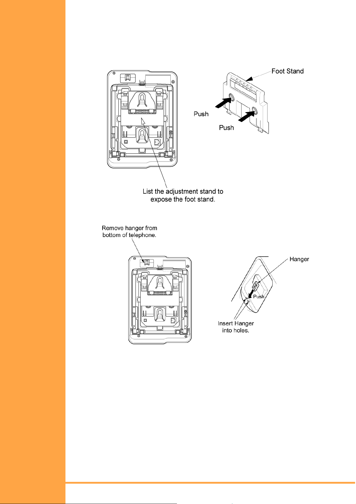
W
S
ALL
ECTION
M
3
OUNTING The DTB-16-1A (BK)/(WH) TEL and DTB-16D-A1 (BK)/(WH) TEL can be mounted to a wall.
1. Locate the stoppers under the height adjustment stand on the bottom of the telephone.
You will need to lift the adjustment stand to expose the foot stand holding the stoppers.
Remove the two plastic stoppers from the foot stand by fir mly pushing on them.
2. Remove the hanger (located on the bottom of the telephone). Insert the hanger into the
holes as indicated in the above diagram.
3. Use the wall mounting template (provided) to mark the screw positions on the wall.
Installation Manual
A6-506000-642-01
Installing DTB Type Multiline Monitors Page 61
• • •
Page 74

4. Insert one end of the telephone line cord into the RJ-11 jack. Route the cord inside the
height adjustment stand as indicated in the diagram. The cord can be wrapped more
than once inside the height adjustment stand to shorten the length of cord. The cord
can exit either the top of the telephone or the side, depending on the most convenient
location of the RJ-11 wall jack.
5. Using a philips head screwdriver, insert the flat head wood screw (provided) into the
stopper and fasten to the wall.
6. to hand the telephone on the wall, place the grooves (located on the bottom of the
telephone) over the plastic stopper, which has been fastened tot he wall. If the
telephone is difficult to mount, you may want to loosen the screws holding the stopper.
7. Insert the other end of the telephone line cord into an RJ-11 jack.
Page 62 Installing DTB Type Multiline Monitors
Installation Manual
• • •
A6-506000-642-01
Page 75

Wall Mounting Template
Use this template to mark the location of the screws on the wall. (Actual size.)
Page 63 Installing DTB Type Multiline Monitors
Installation Manual
• • •
A6-506000-642-01
Page 76

This page is intentionally blank.
Page 64 Installing DTB Type Multiline Monitors
Installation Manual
• • •
A6-506000-642-01
Page 77

C
HAPTER
4
Installing DTU-Type Multiline
Terminals
Xen Alpha Release 1.0
S
ECTION
G
ENERAL
I
NFORMATION
S
ECTION
M
ULTILINE
T
ERMINALS
1
The Xen Alpha system provides four different DTU-Type Multiline Terminals, and several
adapters that allow peripheral equipment to be attached to these Terminals. This chapter
describes each terminal and adapter, it also provides applicable installation instructions.
2
DTU-8-1A (WH) TEL
This digital non-display Multiline Terminal is equipped with eight programmable line keys
(each with a two-colour LED), a built-in speakerphone, headset jack, a large LED to indi cate
incoming calls and messages, and compatibility with ADA-UA, APR-UA, CTA-UA, and HFUUA Units .
Figure 4-1: DTU-8-1A (WH) TEL Multiline Terminal
DTU-8D-1A (WH) TEL
This digital Multiline Terminal has eight programmable line keys (each with the two-colour
LED), four softkeys, a built-in speakerphone, headset jack, a Large LED to indicate
incoming calls and messages, and compatibility with ADA-UA, APR-UA, CTA-UA, and HFUUA Units .
This terminal is also equipped with a 3-line, 24-character, adjustable Liquid Crystal
Display (LCD).
Installation Manual
A6-506000-642-01
Figure 4-2: DTU-8D-1A (BK)/(WH) TEL Multiline Terminal
• • •
Installing DTU Type Multiline Monitors Page 65
Page 78

DTU-16D-1A (WH) TEL
This digital Multiline Terminal has 16 programmable line keys (each with a two-colour LED),
four softkeys, a built-in speakerphone, headset jack, a large LED to indicate incoming calls
and messages, and compatibility with ADA-UA, APR-UA, CTA-UA, and HFU-UA Units.
This terminal is also equipped with a 3-line, 24-character, adjustable Liquid Crystal
Display (LCD).
Figure 4-3: DTU-16D-1A (WH) TEL Multiline Terminal
DTU-32D-1A (WH) TEL
This digital Multiline Terminal has 16 programmable line keys (each with a two-colour LED),
16 one-touch keys, four softkeys, a built-in speakerphone, headset jack, a large LED to
indicate incoming calls and messages, and compatibility with ADA-UA, APR-UA, CTA-UA,
and HFU-UA Units.
This terminal is also equipped with a 3-line, 24-character, adjustable Liquid Crystal
Display (LCD).
System software can be changed so this Multiline Terminal can have 24 programmable line
keys and 8 one-touch keys.
Figure 4-4: DTU-32D-1A (WH) TEL Multiline Terminal
Page 66 Installing DTU Type Multiline Monitors
• • •
Installation Manual
A6-506000-642-01
Page 79

S
ECTION
3
C
ONNECTIN
M
ULTILINE
T
ERMINAL TO THE
S
YSTEM
G
A
These instructions for connecting a Multiline Terminal to the system applies to all of the
DTU-type Multiline Terminals.
1. Plug the telephone cord into the modular jack on the bottom side of the Multiline
Terminal. The handset is also attached to the bottom side of the Multiline Terminal.
Figure 4-5: Connecting a Multiline Terminal to the System
2. Lead the telephone and handset cords through the appropriat e grooves.
Installation Manual
A6-506000-642-01
Figure 4-6: Leading Line Cords on a Multiline Terminal
• • •
Installing DTU Type Multiline Monitors Page 67
Page 80
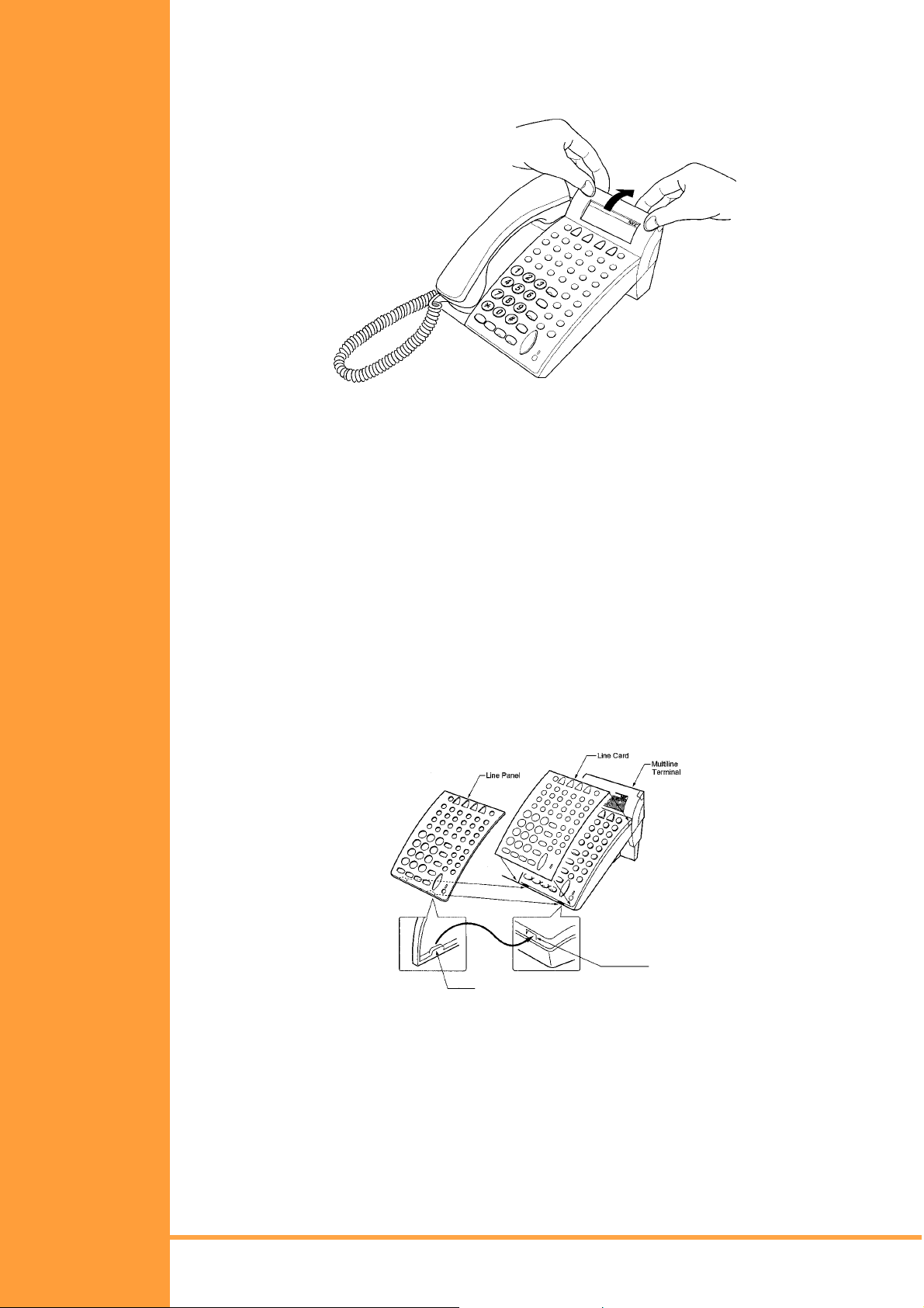
S
ECTION
4
A
DJUSTING THE
LCD
S
ECTION
I
NSTALLING LINE
C
ARDS
P
LASTIC PANELS
5
&
The adjustable Liquid Crystal Display (LCD) comes equipped on the display DTU-type
Multiline Terminals. The LCD can be adjusted by pushing downward and upward as desired.
Figure 4-7: Adjusting the LCD
Line Card and Plastic Panel Installation
Line Cards can be used to print the line key designations. These are then placed on the
Multiline Terminal providing a quick reference of key designations to the Multiline Terminal
users. The Line Cards can be changed as necessary. The Plastic Panel is placed on top of
the Line Card to hold it in place.
1. Place the Line Card over the keys on the Multiline Terminal.
2. Place the tabs on the bottom of the plastic panel into the grooves at the terminal
bottom, and press top right and left ends to secure plastic panel to the
Multiline Terminal. Refer Figure 4-8:: Installing Line Card and Plastic Panel on a
Multiline Terminal, Pg 68.
Figure 4-8: Installing Line Card and Plastic Panel on a Multiline Terminal
Page 68 Installing DTU Type Multiline Monitors
• • •
Installation Manual
A6-506000-642-01
Page 81

Figure 4-9: Installing Plastic Panel
Plastic Panel Removal
Lift the right corner, raise the panel and slide the bottom away from the Multiline Terminal.
NEVER pull on the bottom of the plastic panel to remove it. Damage to
the plastic panel could result
Installation Manual
A6-506000-642-01
Figure 4-10: Removing the Plastic Panel from the Multiline Terminal
• • •
Installing DTU Type Multiline Monitors Page 69
Page 82
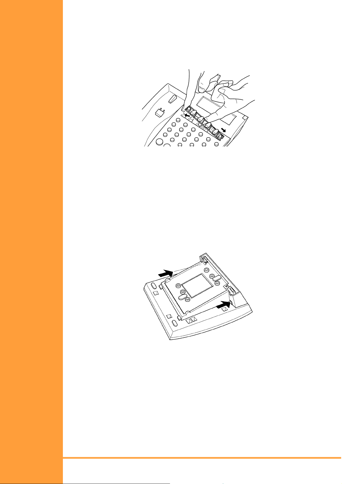
S
ECTION
R
S
6
EMOVING
OFTKEYS
If softkeys are not going to be used on the Multiline Terminal they can be removed. This
section describes the process for removing the keys.
1. Remove the softkeys by pulling the softkey plate upward as shown in Figure 4-11::
Removing Softkeys, Pg 70..
Figure 4-11: Removing Softkeys
2. Install the plastic panel again.
S
ECTION
A
DJUSTING THE
H
EIGHT OF THE
M
ULTILINE
T
ERMINAL
7
The base plate on DTU-type Multiline Terminals are hinged. The bottom portion can be
adjusted up or down to raise or lower the height of the termina l.
1. Turn the Multiline Terminal upside down and locate the tabs as shown in Figure 4-12::
Locating the Adjustment Tabs on the Multiline Terminal, Pg 70.
Figure 4-12: Locating the Adjustment Tabs on the Multiline Terminal
Page 70 Installing DTU Type Multiline Monitors
• • •
Installation Manual
A6-506000-642-01
Page 83
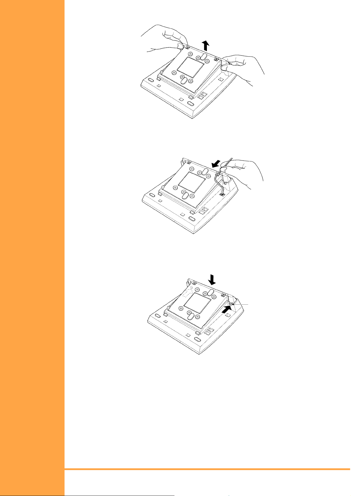
2. Push the adjustment tabs and raise the base plate until it locks.
Figure 4-13: Raising the Base Plate on the Multiline Terminal
3. The length of the cord can be adjusted by pulling the line cord though the groove in the
bottom of the Multiline Terminal.
Figure 4-14: Adjusting the Line Cord Length
4. To lower the base plate on the Multiline Terminal, push on the adjustment tabs and push
the base plate downward.
Figure 4-15: Lowering the Base Plate on the Multiline Terminal
Installation Manual
A6-506000-642-01
• • •
Installing DTU Type Multiline Monitors Page 71
Page 84
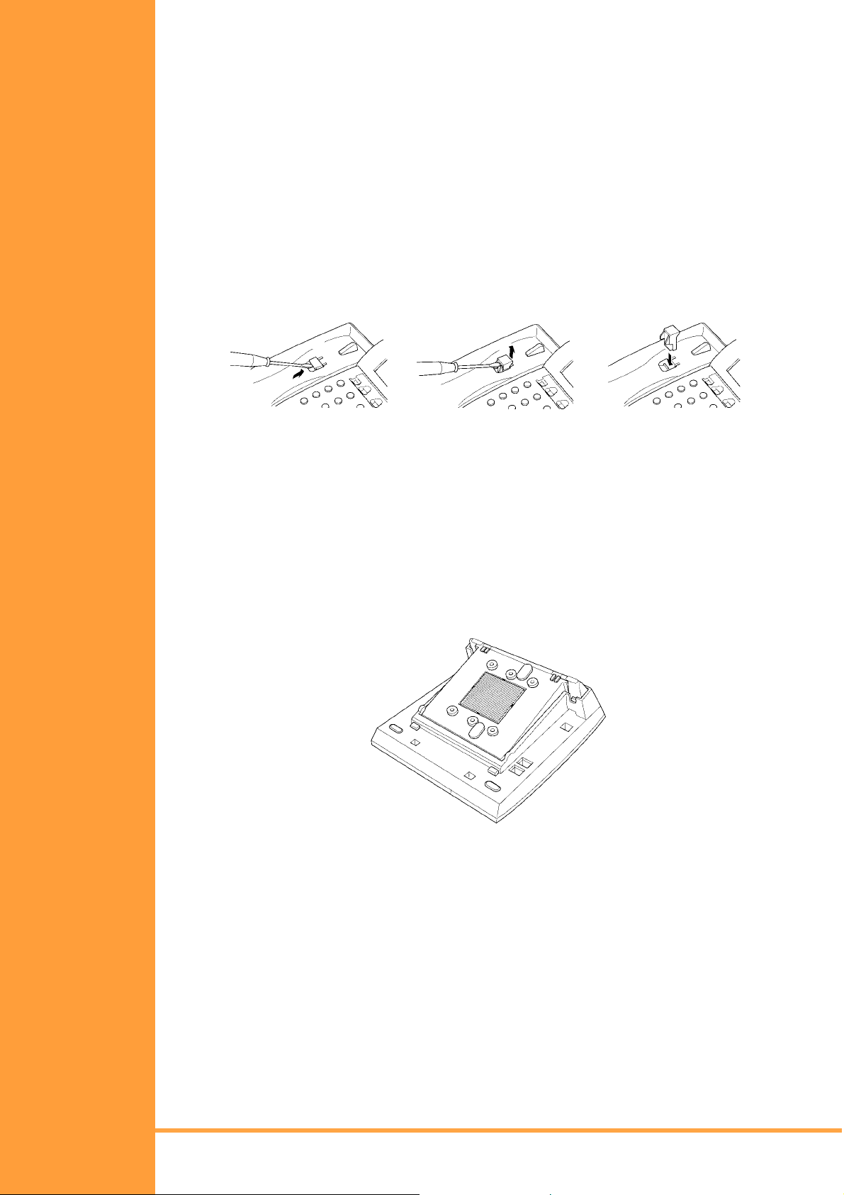
W
S
ALL
ECTION
M
8
OUNTING Any DTU-Type Multiline Terminal can be mounted on a wall. Multiline Terminals can be wall
mounted by using the base unit t hat comes with the Multil ine Terminal or by using the WMUUA Unit to accommodate adapters that are installed on the Multil ine Terminal.
Removing and Remounting the Handset Hanger
1. Remove the hanger by sliding it out of the slot.
2. Install it back in its original position so that the hanger protrudes providi ng a rest for the
handset. (This procedure applies when using either the base uni t or the WMU-UA Unit. )
Refer to Figure 4-16:: Posi tioni ng the Handset Hanger, Pg 72 for the steps for removing
and remounting the handset hanger.
"#$
Figure 4-16: Positioning the Handset Hanger
Wall Mounting, Using the Base Unit
1. Refer to Section 9: Preparing Multiline Terminal for Adapter Installation, Pg 78, and
perform Steps 1 – 5.
2. Press both sides of the base cover and turn it left to remove it.
3. Rotate base cover 180° and install it again on the Multiline Terminal.
4. Remove the shaded base plate knockout shown on Figure 4-17:: Removing the
Knockout, Pg 72
Figure 4-17: Removing the Knockout
Page 72 Installing DTU Type Multiline Monitors
• • •
Installation Manual
A6-506000-642-01
Page 85
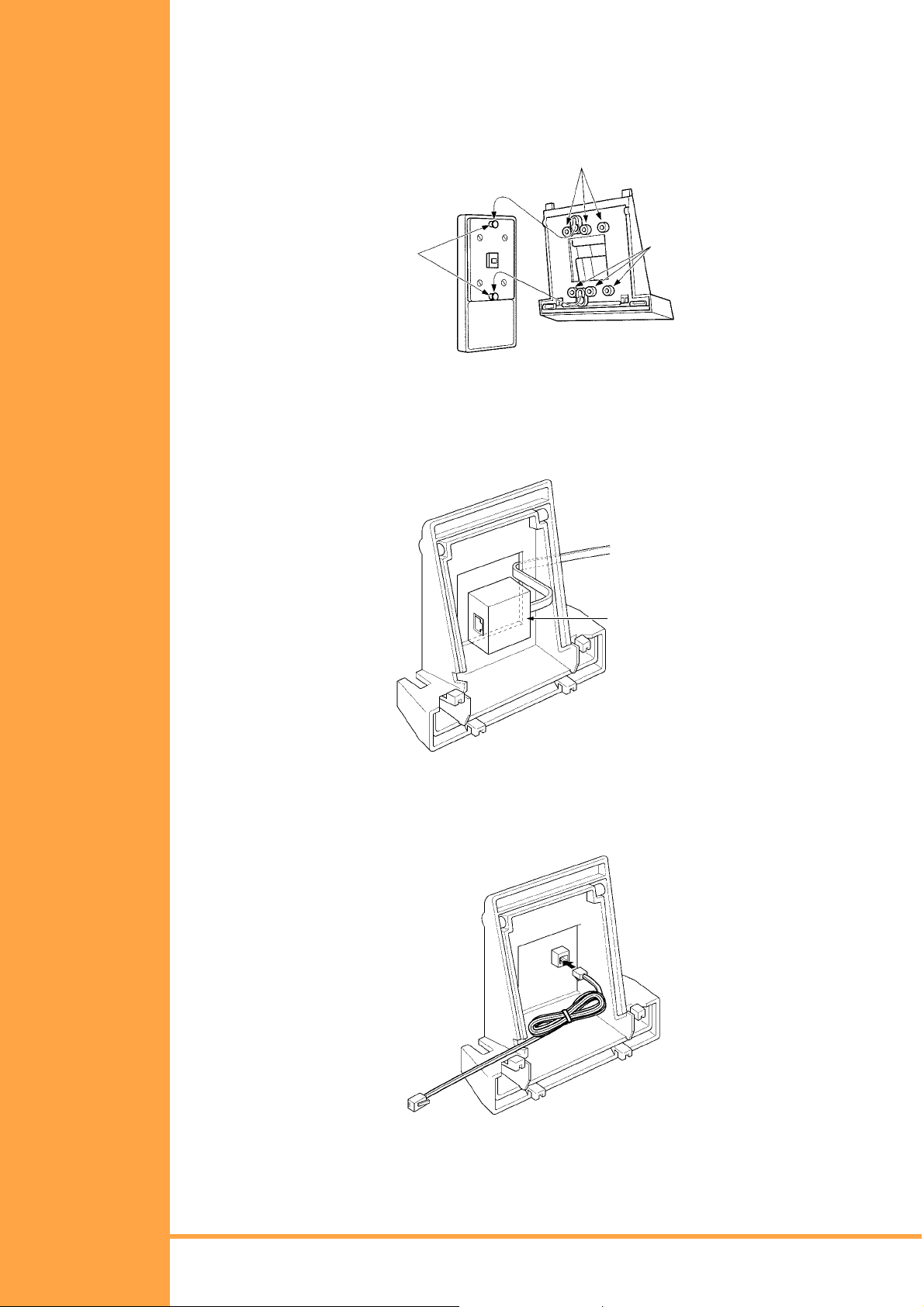
5. Assemble the base plate and base cover.
6. As illustrated in Figure 4-18:: Attaching the Base Plate to the Wall, Pg 73, attach the
base plate and base cover assembly (wide end down) to the posts on the locally
provided and installed wall plate. Place locally provided screws in the nodes on the
base plate and secure the assembly to the wall.
Nodes
Posts
Nodes
Figure 4-18: Attaching the Base Plate to the Wall
If using a modular jack instead of a wall plate, put the modular jack inside the base unit
as shown in Figure 4-19:: Wall Mounting using a Modular Jack, Pg 73. Use the locally
provided screws to attach the base unit directly to the wall.
Modular
Terminal
Figure 4-19: Wall Mounting using a Modular Jack
7. Plug the line cord into the jack on the wall plate, wrap the extra cord and secure it with a
tie wrap, and lead the line cord out through the groove in the side of the base unit .
Figure 4-20: Plugging in the Line Cord using a Wall Jack
Installation Manual
A6-506000-642-01
• • •
Installing DTU Type Multiline Monitors Page 73
Page 86
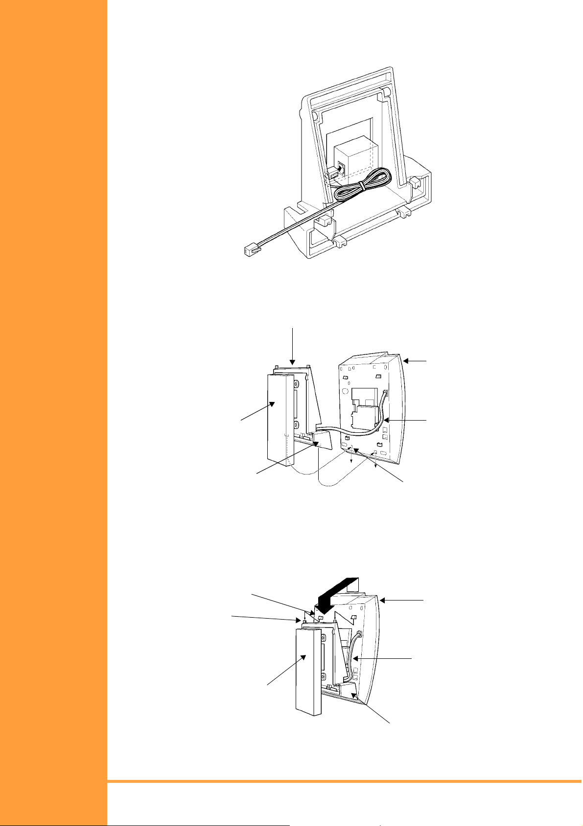
If using a modular jack instead of a wall plate, plug the line cord into the modular jack,
wrap the extra cord and secure it with a tie wrap, and lead the line cord out through the
groove in the side of the base unit.
Figure 4-21: Plugging in the Line Cord Using a Modular Jack
8. With the base plate and base cover asse mbly att ached to t he wall, hook the t wo bot tom
tabs on the base cover into the tab slots on the base of the Multiline Terminal.
Base Unit
Multiline
Terminal
Wall
Tab
Line Cord
Tab Slots
Figure 4-22: Attaching the Bottom Tabs of the Multiline Terminal to the Base Cover
9. Push up on the Multiline Terminal and lock the top tabs on the base cover into the tab
slots on the base of the Multiline Terminal. Turn terminal slightly clockwise to interface
with base cover. Figure 4-23:: Attaching the Top Tabs of the Multiline Terminal to the
Base Plate, Pg 74 shows how the Multiline Terminal is attached.
Tab Slots
Tabs
Multiline
Terminal
Line Cord
Wall
Wall Mount
Unit
Figure 4-23: Attaching the Top Tabs of the Multiline Terminal to the Base Plate
Page 74 Installing DTU Type Multiline Monitors
• • •
Installation Manual
A6-506000-642-01
Page 87
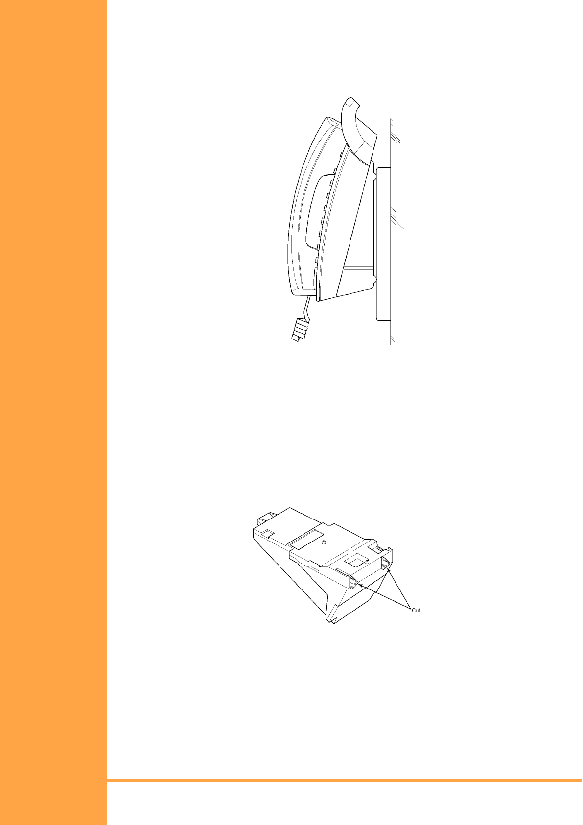
10. When properly installed, the wall-mounted Multiline Terminal looks similar to the one
shown in Figure 4-24:: Installed Wa ll Mount Unit, Pg 75.
NOTE: Do not adjust the tilt panel LCD after the Multiline Terminal is mounted on
the wall.
.
Figure 4-24: Installed Wall Mount Unit
Installing the Wall Mount Unit & Mounting the Multiline Terminal Using the
WMU-UA Unit
If installing an HFU-UA Unit, CTA-UA Unit, or APR-UA Unit, a separate WMU-UA Unit must
be purchased to accommodate these units.
1. Remove the line cord, base plate and base cover from the Multiline Terminal as shown
in the previous section.
2. Cut off the tabs on the adapter as shown in Figure 4-25:: Removing the Tabs from the
Adapter, Pg 75.
Figure 4-25: Removing the Tabs from the Adapter
Installation Manual
A6-506000-642-01
• • •
Installing DTU Type Multiline Monitors Page 75
Page 88
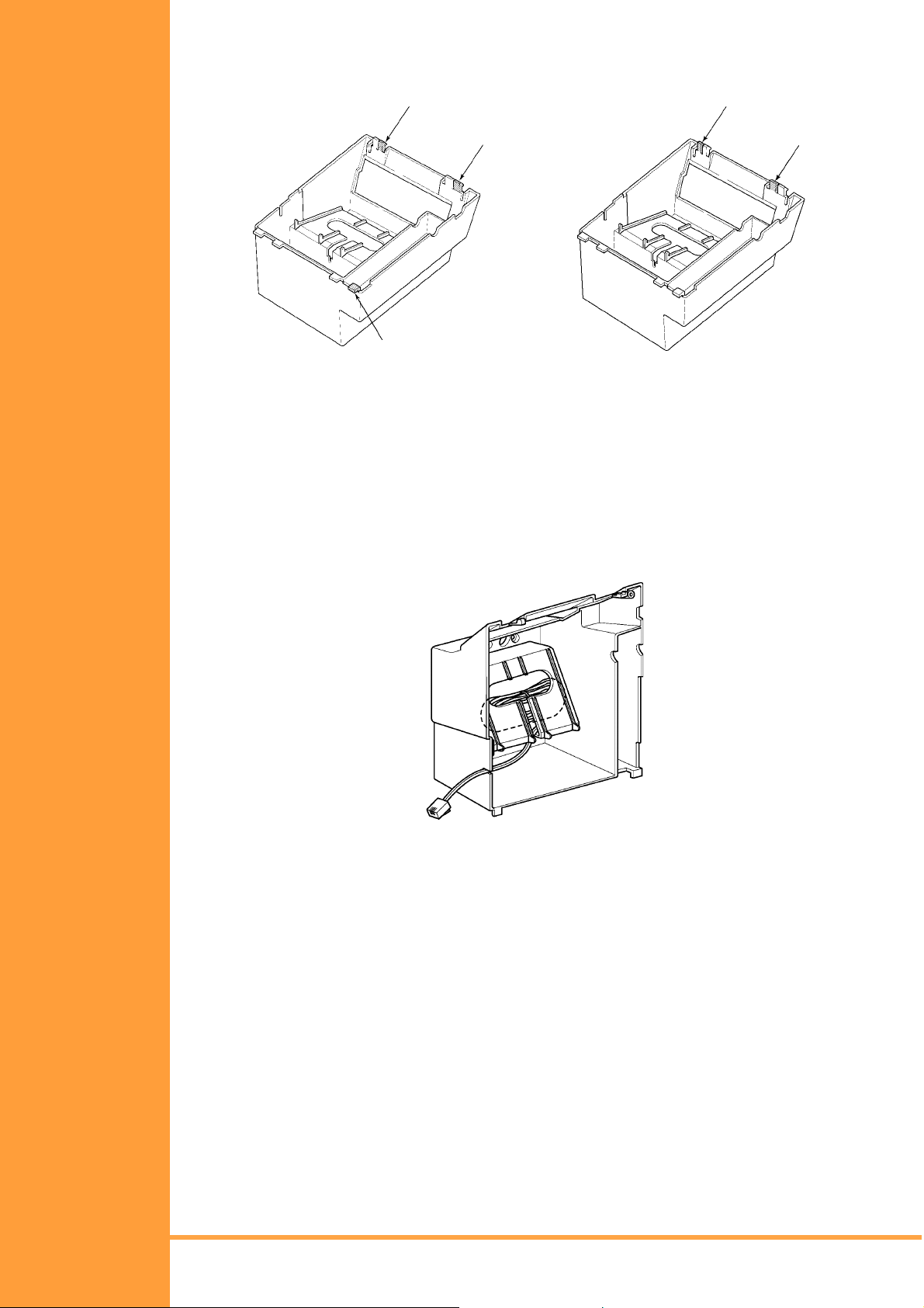
3. Remove the tabs from the WMU-UA Unit as shown in Figure 4-26:: Removing the Tabs
from the WMU-UA Unit, Pg 76. (Tabs removed depends on the Multiline Terminal type.)
Cut
DTU-8-1A (WH) TEL
Cut
Cut
DTU-32D-1A (WH) TEL
Cut
Cut
DTU-8D-1A (WH) TEL
DTU-16D-1A (WH) TEL
Figure 4-26: Removing the Tabs from the WMU-UA Unit
4. Bundle the cord from the modular jack leaving about eight inches. Use a tie wrap to
secure the bundled cord.
5. Place the bundled line cord in the space between the WMU-UA Unit and the wall. Lead
the line cord out through the slits as shown in Figure 4-27:: Leading the Line Cord out
of the WMU-UA Unit, Pg 76.
Figure 4-27: Leading the Line Cord out of the WMU-UA Unit
Page 76 Installing DTU Type Multiline Monitors
• • •
Installation Manual
A6-506000-642-01
Page 89

6. Attach the WMU-UA Unit to the posts on the wall plate (locally provided). Place locally
provided screws in the nodes on the WMU-UA Unit and secure the WMU-UA Unit to
the wall.
Nodes
Posts
Nodes
Figure 4-28: Attaching the Wall Mount Unit to the Wall
7. Connect the line cord to the Multiline Terminal.
8. With the WMU-UA Unit attached to the wall, hook the two bottom tabs on the WMU-UA
Mount Unit into the tab slots on the Multiline Terminal. Then push the two top tabs on
the WMU-UA Unit into the tab slots o n the Multil ine Terminal. If the adapter has a power
supply, lead the AC adapter cord out through the opening at the bottom of the Multiline
Terminal. Refer to Figure 4-29:: Attaching the Multiline Terminal to the WMU-UA Unit,
Pg 77.
WMU-UA Unit
Multiline Terminal
Adapter
Tab Stops
Wall
Installation Manual
A6-506000-642-01
Figure 4-29: Attaching the Multiline Terminal to the WMU-UA Unit
• • •
Installing DTU Type Multiline Monitors Page 77
Page 90

Removing the Multiline Terminal from the Base Cover
To remove the Multiline Terminal from the base cover, lift the Multil ine Terminal to disengage
top tabs, turn it slightly counter cl ockwise to unl ock lower tabs on base cover, and remove it.
Figure 4-30: Removing the Multiline Terminal from the Base Cover
S
ECTION
I
NSTALLING
O
A
9
PTIONAL
DAPTERS
Removing the Multiline Terminal from the WMU-UA Unit
To remove the Multiline Terminal from the WMU-UA Unit, lift the Multiline Terminal to
disengage top tabs and lower the terminal from the WMU-UA Unit.
Optional equipment is available to enhance the Xen system. This equipment can be
purchased separately from the system and added as the customer busi ness needs grow. All
these adapters can be installed on the DTU-Type Xen Multiline Terminals.
A Multiline Terminal can have up to three adapters installed a t the same ti me. If a ttachi ng an
APR-UA Unit, a CTA-UA Unit, or an HFU-UA Unit, an external power supply is required.
Only one power supply is needed even if more than one adapter is installed.
When an adapter is installed for the first time into a telephone, the base cover on the
Multiline Terminal may have to be modified. The base cover has two access panels that are
removed before the cover can be closed over the adapters to complete the installation.
Preparing Multiline Terminal for Adapter Installation
To prepare the Multiline Terminal for adapter installation:
1. Unplug the telephone cord from the terminal.
2. Turn the terminal upside down. Push the tabs indicated in Figure 4-31:: Raising the
Base Plate, Pg 78, and raise the inner area of the base plate.
Figure 4-31: Raising the Base Plate
Page 78 Installing DTU Type Multiline Monitors
• • •
Installation Manual
A6-506000-642-01
Page 91

3. Insert flat head screwdriver into A in Figure 4-32:: Unlocking Tab, Pg 79 and press
straight down until tab unlocks.
Figure 4-32: Unlocking Tab
4. Lightly press right side of leg shown as B in Figure 4-33:: Releasing Right Tab, Pg 79,
insert flat head screwdriver at C and Press straight down until other tab unlocks.
Figure 4-33: Releasing Right Tab
5. Open and remove Bottom Cover by rot ating count erclo ckwise a s s hown in Fi gure 4-34::
Removing Bottom Cover, Pg 79.
Figure 4-34: Removing Bottom Cover
6. If an adapter is being installed, press tabs A and B to remove the dummy end from the
base plate as shown in Figure 4-35:: Removing Base Plate Dummy End, Pg 79.
Installation Manual
A6-506000-642-01
Figure 4-35: Removing Base Plate Dummy End
• • •
Installing DTU Type Multiline Monitors Page 79
Page 92

7. Cut the dummy end in half as shown in Figure 4-36:: Cutting Dummy End in Half, Pg
80.
Figure 4-36: Cutting Dummy End in Half
8. If Adapter is installed in Connector 1 as show in Figure 4-37:: Installing Adapter in
Connector 1, Pg 80, Install Dummy end B as shown in Figure 4-38:: Installing Dummy
End B, Pg 80.
Figure 4-37: Installing Adapter in Connector 1
Figure 4-38: Installing Dummy End B
ACA-UA Unit (AC Adapter)
This unit provides power to ancillary devices or Attendant Consoles. The ACA-UA Unit must
be connected to an adapter that is installed on a Multiline Terminal. If more than one adapter
is installed on a Multiline Terminal, only one ACA-UA Unit is necessary.
The power requirements for the ACA-UA Unit are:
• Input: 240 Vac, 50 Hz
• Output: 24V DC, 400 mA
• Polarity:
Page 80 Installing DTU Type Multiline Monitors
• • •
Installation Manual
A6-506000-642-01
Page 93

1. Connecting the ACA-UA Unit
a) Unplug the line cord from the Multiline Terminal and unplug the ACA-UA Unit from
the AC outlet. (Failing to do this can damage the unit and/or the
Multiline Terminal.)
b) Turn the Multiline Terminal upside down and open the base plate.
2. Locate the AC adapter plug on the ancillary device that is connected to the bottom of
the Multiline Terminal and plug in the AC adapter.
Figure 4-39: ACA-UA Unit Connection
ADA-UA Unit (Ancillary Device Adapter)
Ancillary Device Adapters allow connection of a recording device to DTU-type
Multiline Terminals.
When installing an ADA-UA Unit, first connect the cables to the ADA-UA Unit, set the dip
switches, and then install the ADA-UA Unit on the Multiline Terminal.
1. Installing an ADA-UA Unit on a Multiline Terminal
a) Unplug the telephone cord from the Multiline Terminal.
b) Prepare Multiline Terminal for adapter installation. Refer to Section 2 Preparing
Multiline Terminal for Adapter Installation.
c) Plug the ADA-UA Unit connector into the receptacle connector on the back of the
Multiline Terminal. Snap the ADA-UA Unit into the hooks on the Multiline Terminal
to secure it.
Installation Manual
A6-506000-642-01
Figure 4-40: Attaching the ADA-UA Unit to the Multiline Terminal
d) Replace base plate.
• • •
Installing DTU Type Multiline Monitors Page 81
Page 94

e) Lead the audio cable out through the groove on the base cover. Plug in the
telephone cord.
Figure 4-41: Leading the Audio Cable out from the ADA-UA Unit
Connecting Cables to the ADA-UA Unit
Cable terminal connectors are located on the right side of the ADA-UA Unit. Cables should
be connected on this unit before installing the unit on the Multiline Terminal.
Figure 4-42: ADA-UA Unit
1. Cut off the plug on one end of the cable.
2. Locate the adapter terminals on the right side of the unit as illustrated in Figure 4-42::
ADA-UA Unit, Pg 82.
3. Remove the cap on the adapter terminal to expose the metal receptacle. Push the
cable in the applicable recept acle, and replace the cap. Line up the slot on the cap with
the slot on the metal receptacle to ensure proper contact. Refer to Figure 4-43::
Attaching Cables to the ADA-UA Unit, Pg 82.
Figure 4-43: Attaching Cables to the ADA-UA Unit
Page 82 Installing DTU Type Multiline Monitors
• • •
Installation Manual
A6-506000-642-01
Page 95

4. Insulate the end of the cable that needs to be shielded with insulating tape.Table 4-3:
ADA-UA Cable Connections, Pg 83 provides a list of cable connections to ADA-UA
ADP terminals and describes the specifications for the terminals.
Table 4-3: ADA-UA Cable Connections, Pg 83 provides a list of cable connections to
ADA-UA ADP terminals and describes the specifications for the term inals.
Table 4-3 ADA-UA Cable Connections
Terminal
Number
T1
T2
T3
T4
T5
Cables to Connect Terminal Specifications
When warning tone is not being sent
from the recorder, connect wire pair input
from tone generator to T1:T2. The
warning tones from the generator are
sent to T1:T2 on a dedicated wire pa ir
while the speech path is sent from the
ADA-UA on T3:T4 over a separate wire
pair to the recorder.
Connect recorder device wire pair
speech in put to T3:T4.
If the recorder used supplies a warning
tone, this tone may also be sent over the
T3:T4 wire pair back to the terminal.
Connect the bare end of the control
cable.
Input Terminal:T1 and T2 are enabled
for tone generating
device when DIP
switches 3 and 4 are
OFF.
(If switches 3 and 4 are ON, a humming
sound may be recorded due to
impedance mismatch.)
Input Impedance on T1 and T2: 100K
<Symbol>W
Input Level on T1 and T2: –15 dB ~ 40
dB
Input/Output Terminal:
Refer to dip switch settings in
Table 44: ADA-UA Unit Switch Settings, Pg
85
.
When a Multiline Terminal is idle, this
contact is closed. When the Multilin e
Terminal goes off-hook (using the
handset, headset, or speakerphone),
this contact is open.
If recorder owner manual specifies
start on open circuit, c onnect T5 and
T6.
Installation Manual
A6-506000-642-01
T6
T7
T8
T9
• • •
Installing DTU Type Multiline Monitors Page 83
Connect the shielded end of the control
cable.
Connect the bare end of the control
cable.
Unused
Unused
Provides common connecti on for
control cable.
When the Multiline Terminal is idle, this
contact is open. When the Multiline
Terminal is busy (using the handset,
headset, or speakerphone), this contact
is closed.
If recorder owner manual specifies
start on closed circuit, connect T6
and T7.
Page 96
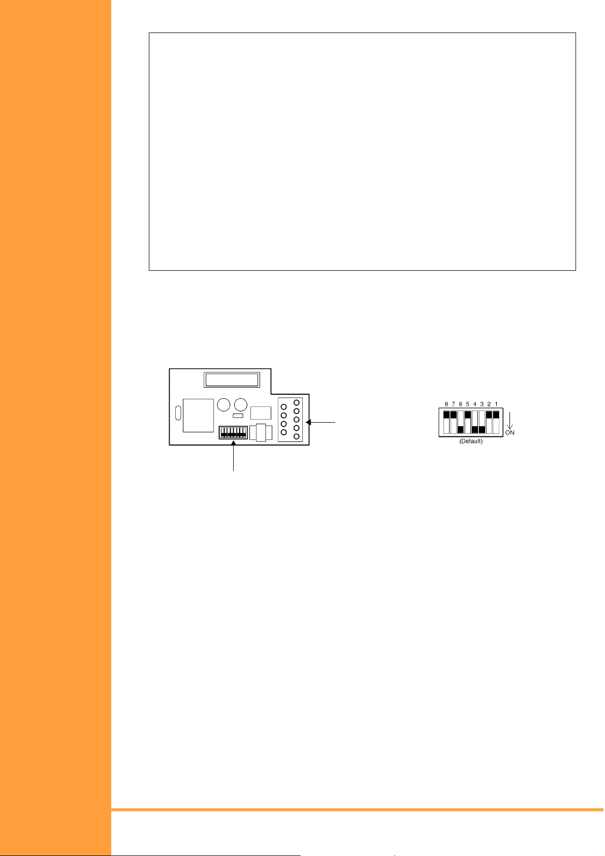
Table 4-3 ADA-UA Cable Connections (Continued)
Notes:
☛ When recording in handsfree (half-duplex) m ode using the built-in spe akerphone, the
record warning tone may not be audible to the far-end party.
☛ The transmit recording level is lower than the receiving voice level for intercom calls; the
transmit recording level for CO calls is normal.
☛ Depending on the recording device(s), separate cables may be required for the warning
tone and speech p ath. In this cas e, connect the war ning tone ca bles to input ter minals
T1 and T2 on the ADA-UA Unit. (T3 and T4 are used as the Analogue recorder input.)
☛ If remote control of the recorder is necessary, the record start/stop control is provided by
connecting to T5 (or T7) and T6 on the ADA-UA Unit. (Connecting to T5 or T7 is
determined by the specifications of the recorder.)
☛ If a warning Tone is provided from the recording equipment, it should be input via T3 and
T4 on ADA-UA Unit. (Do not use T1 and T2 to input Beep Tone.)
☛ Conversations cannot be recorded from terminals connected to an APR-UA Unit.
Speakerphone calls through the HFU-UA Unit cannot be recorded.
Switch Settings
The DIP Switch is located at the bot tom c enter o f the ADA-UA Uni t. T he DIP Swi tch al lows a
technician to configure the board to specific settings. Figure 4-44:: ADA-UA Unit Switch
Settings, Pg 84 shows the default settings.
Terminals
Default Settings
Dip Switch
Figure 4-44: ADA-UA Unit Switch Settings
Page 84 Installing DTU Type Multiline Monitors
• • •
Installation Manual
A6-506000-642-01
Page 97

The following switch settings should be made on the ADA-UA Unit to enable or disable the
record start warning tone. Swit ch se ttin gs should be made b efor e i nsta lling the ADA-UA Unit
in the Multiline Terminal. (Refer to Table 4-4: ADA-UA Unit Switch Settings, Pg 85.)
Table 4-4 ADA-UA Unit Switch Settings
Switch Setting Description
If the ADA-UA provides
control to the recorder,
SW1–1 On
SW1–2 Off
SW1–3
ON
SW1–3
and
SW1-4
SW1–5
and
SW1–6
SW1–3
OFF
SW1–5
OFF
SW1–5
ON
SW1–4
ON
SW1–4
OFF
SW1–6
ON
SW1–6
OFF
SW1-1 should be set to
On, otherwise set it to
Off.
Leave Off
Warnin g Tone from
recording device over
same wire pair as
speech path.
Warnin g Tone from
recorder or generator
equipment on dedicated
wire pair to recorder
MIC input
Input impedance is 600
<Symbol>W
Input impedance is less
than 600<Symbol>W
If warning tone from any
SW1–7 ON
SW1–8 Off
☛ Do not connect T1 and T2 when switches 3 and 4 are ON.
device is sent to
telephone
Leave Off
Installation Manual
A6-506000-642-01
• • •
Installing DTU Type Multiline Monitors Page 85
Page 98
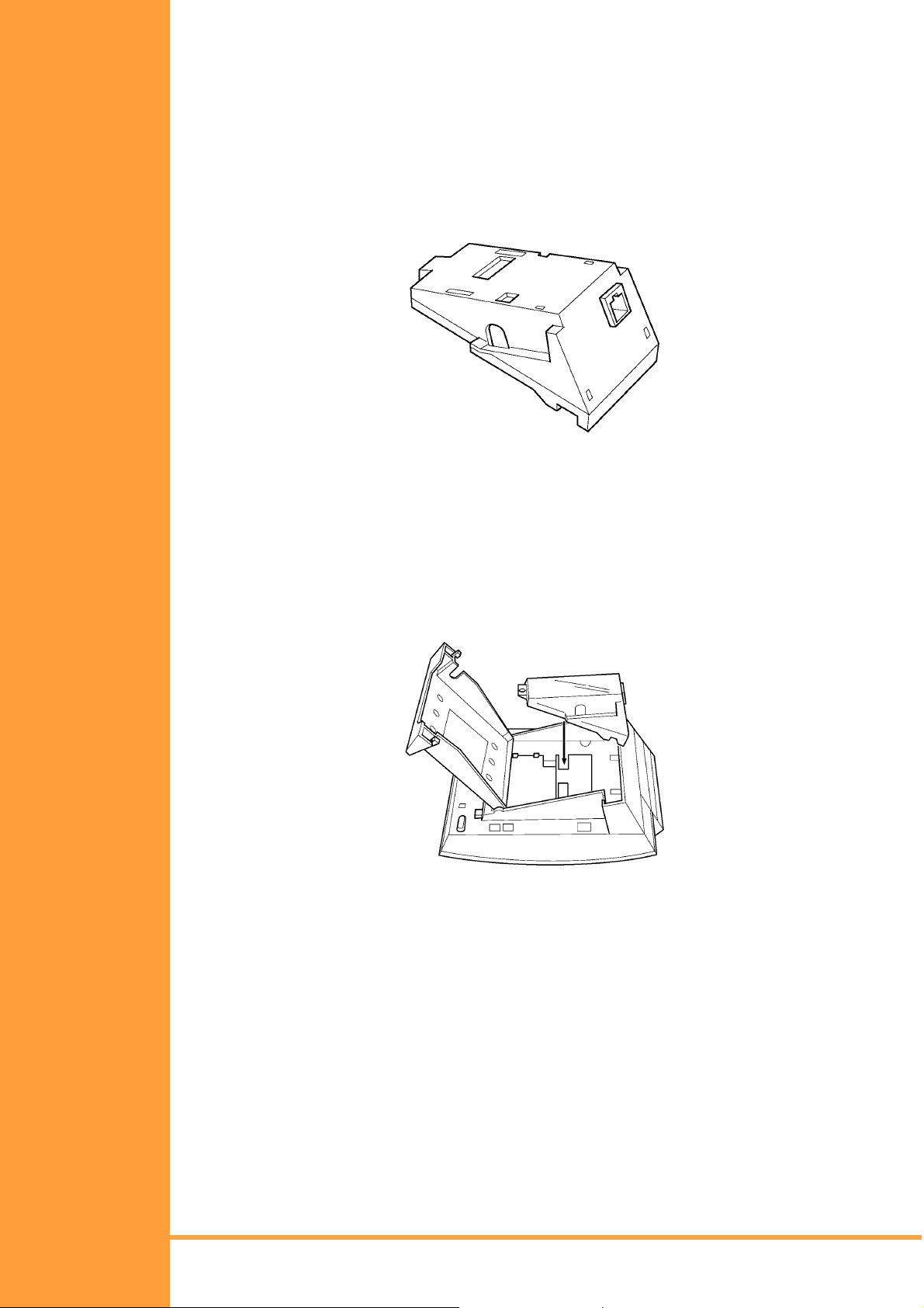
APR-UA Unit (Analogue Port Ringer)
The Analogue Port adapter with Ringing provides an interface for installing Single Line
Telephones, modems, NEC VoicePoint Conferencing unit, and other compatible analogue
devices. The APR-UA Unit also generates ringing signals. By providing ring generation, the
user can install a personal fax machine or an answering machine for convenience. Two
user-adjustable switches are provided on the adapter; one allows for 600<Symbol>W or a
complex impedance interface to devices such as a modem or Single Line Telephone, the
second switch (SW1) is permanently set to position 2. The APR-UA Unit requires an AC
adapter (ACA-UA Unit). If a CTA-UA Unit or the HFU-UA Unit and an APR-UA Unit are both
installed, only one AC adapter is required.
Figure 4-45: APR-UA Unit
Installing a n AP R-UA Unit on a Mu lt iline Terminal
1. Unplug the telephone cord from the Multiline Terminal.
2. Prepare Multiline Terminal for adapter installation. Refer to Section 9: Preparing
Multiline Terminal for Adapter Installation, Pg 78.
3. Plug the unit into the receptacle connector inside the base plate. Refer to Figure 4-46::
Attaching the Unit to the Multiline Terminal, Pg 86.
Figure 4-46: Attaching the Unit to the Multiline Terminal
Page 86 Installing DTU Type Multiline Monitors
• • •
Installation Manual
A6-506000-642-01
Page 99
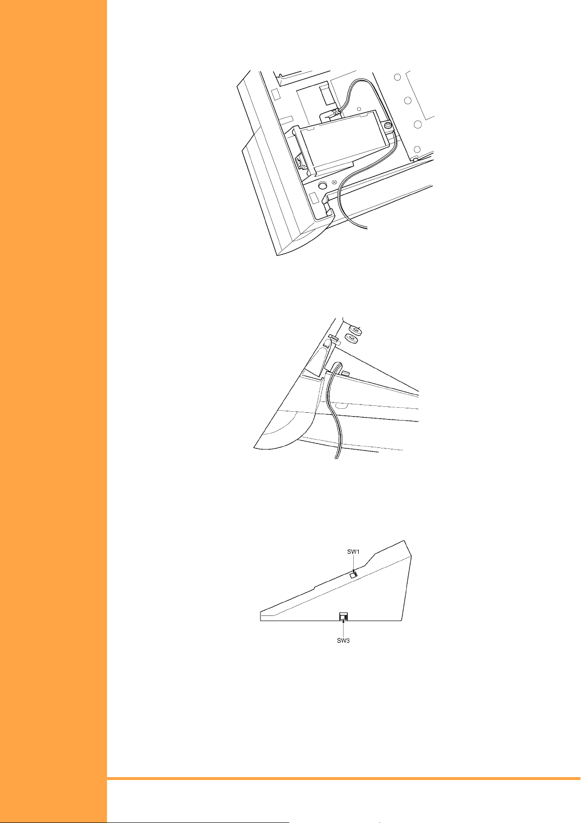
4. Plug the cord of the ACA-UA Unit (AC adapter) into the jack on the APR-UA Unit. Lead
the telephone cord out through the groove in the base as shown in Figure 4-47::
Leading the Telephone Cord out from the Unit, Pg 87.
Figure 4-47: Leading the Telephone Cord out from the Unit
5. Close the base plate, lead the AC adapter cord out through the hole, and snap the
cover in place.
Figure 4-48: Closin g the Base Plate Cover
6. Plug in the power cord on the AC adapter and the telephone cord in the jack.
Switch Settings
There are two switch settings on the APR-UA Unit.
Figure 4-49: APR-UA Unit Switches
Installation Manual
A6-506000-642-01
• • •
Installing DTU Type Multiline Monitors Page 87
Page 100

The following table lists the switch settings for SW1 and SW3.
Switch Description
SW1–1
SW1–2
SW3–1
SW3–2
Do not use
A Single Lin e Telephone an d M ultiline Terminal
are used alternately.
(The Multilin e Terminal and the APR -UA Unit
share the same B1 channel.)
Sets impedance to 600<Symbol>W for devices
such as modems or facsimile machines
Used for complex impedance devices such as
Single Line Telephones.
Connecting Cables on the APR-UA Unit
Plug the telephone cord from the Single Line Telephone into the modular jack on the APRUA Unit.
Limit the cable length from the APR-UA Unit to the Single Line Telephone to a maximum of
15 metres.
Figure 4-50: Connecting Cables on the APR-UA Unit
Page 88 Installing DTU Type Multiline Monitors
• • •
Installation Manual
A6-506000-642-01
 Loading...