

Page 1

User’s Guide
SA2500/WA2500
Page 2

This page is intentionally left blank.
Page 3

User Guide
3
www.nec-computers.com
100
Proprietary Notice and Liability Disclaimer
The information disclosed in this document, including all designs and related materials, is the
valuable property of NEC Computers and/or its licensors. NEC Computers and/or its licensors,
as appropriate, reserve all patent, copyright and other proprietary rights to this document,
including all design, manufacturing, reproduction, use, and sales rights thereto, except to the
extent said rights are expressly granted to others.
The NEC Computers product(s) discussed in this document are warranted in accordance with
the terms of the Warranty Statement accompanying each product. However, actual
performance of each product is dependent upon factors such as system configuration, customer
data, and operator control. Since implementation by customers of each product may vary, the
suitability of specific product configurations and applications must be determined by the
customer and is not warranted by NEC Computers.
To allow for design and specification improvements, the information in this document is subject
to change at any time, without notice. Reproduction of this document or portions thereof without prior written approval of NEC Computers is prohibited.
Trademarks
Adobe, and Adobe Acrobat are registered trademarks of Adobe Systems, Incorporated.
Microsoft, Microsoft Windows, Windows NT, Windows 95, Windows 98, Windows 2000 and
Windows Storage Server 2003 are all registered trademarks of Microsoft Corporation.
MS-DOS is a registered trademark of Microsoft Corporation.
Intel and Pentium are registered trademarks of Intel Corporation.
All other product, brand, or trade names used in this publication are the trademarks or registered
trademarks of their respective trademark owners.
rev 0.0 October 2005
Copyright 2005
NEC Computers S.A.S.
10 rue Godefroy
Immeuble OPTIMA
92821 PUTEAUX
All Rights Reserved
Page 4

User Guide
1
www.nec-computers.com
Text Conventions . . . . . . . . . . . . . . . . . . . . . . . . . . . . . . . . . . . . . . . . . . . . . . . . . . . . . . . . . . . . . . 7
Safety Notices . . . . . . . . . . . . . . . . . . . . . . . . . . . . . . . . . . . . . . . . . . . . . . . . . 8
Regulatory Information . . . . . . . . . . . . . . . . . . . . . . . . . . . . . . . . . . . . . . . . . . . . . . . . . . . . . . . . . 8
European Notice .............................................................................................................. 8
USA and Canada Notice.................................................................................................. 9
Modifications to the Product............................................................................................ 9
Connections and Remote Earths...................................................................................... 9
Power Supply and Cables.............................................................................................. 10
Batteries......................................................................................................................... 10
Chassis Cover Removal and Replacement .................................................................... 10
Laser Compliance Statement......................................................................................... 11
Warning - Hazardous Voltage!...................................................................................... 11
Warning -Avoid Electrostatic Discharge!...................................................................... 11
Product Disposal............................................................................................................ 11
System Features . . . . . . . . . . . . . . . . . . . . . . . . . . . . . . . . . . . . . . . . . . . . . .12
Related Documents . . . . . . . . . . . . . . . . . . . . . . . . . . . . . . . . . . . . . . . . . . . . . . . . . . . . . . . . . . . 13
System Chassis Features . . . . . . . . . . . . . . . . . . . . . . . . . . . . . . . . . . . . . . . . . . . . . . . . . . . . . . 14
Front View..................................................................................................................... 14
Rear View...................................................................................................................... 16
Status Indicators . . . . . . . . . . . . . . . . . . . . . . . . . . . . . . . . . . . . . . . . . . . . . . . . . . . . . . . . . . . . . 18
Front Panel..................................................................................................................... 18
Back Panel ..................................................................................................................... 18
Internal View ................................................................................................................. 19
Motherboard................................................................................................................... 20
Configuring MotherBoard Jumpers............................................................................... 21
Back Panel Connectors.................................................................................................. 24
Memory Configuration.................................................................................................. 24
Standard Features . . . . . . . . . . . . . . . . . . . . . . . . . . . . . . . . . . . . . . . . . . . . . . . . . . . . . . . . . . . . 26
Processor........................................................................................................................ 26
Memory.......................................................................................................................... 26
PCI Slots........................................................................................................................ 26
PCI -Express Slots......................................................................................................... 26
Network Controller........................................................................................................ 26
RAID Controller............................................................................................................ 27
ACPI .............................................................................................................................. 27
Keyboard and Mouse..................................................................................................... 27
Peripheral Bays.............................................................................................................. 27
Peripheral Bays.............................................................................................................. 28
Optional Features . . . . . . . . . . . . . . . . . . . . . . . . . . . . . . . . . . . . . . . . . . . . . . . . . . . . . . . . . . . . 29
CD-ROM Drive . . . . . . . . . . . . . . . . . . . . . . . . . . . . . . . . . . . . . . . . . . . . . . . . . . . . . . . . . . . . . . . 30
DVD-ROM Drive . . . . . . . . . . . . . . . . . . . . . . . . . . . . . . . . . . . . . . . . . . . . . . . . . . . . . . . . . . . . . . 31
DVD +R9 Combination Drive . . . . . . . . . . . . . . . . . . . . . . . . . . . . . . . . . . . . . . . . . . . . . . . . . . . . 32
DVD+R9 (DL) Drive . . . . . . . . . . . . . . . . . . . . . . . . . . . . . . . . . . . . . . . . . . . . . . . . . . . . . . . . . . . 33
DAT72 Tape Backup Unit (SCSI) . . . . . . . . . . . . . . . . . . . . . . . . . . . . . . . . . . . . . . . . . . . . . . . . 35
Sony AIT-1 Turbo Backup Unit (IDE) . . . . . . . . . . . . . . . . . . . . . . . . . . . . . . . . . . . . . . . . . . . . . 36
Sony AIT-2 Turbo Backup Unit . . . . . . . . . . . . . . . . . . . . . . . . . . . . . . . . . . . . . . . . . . . . . . . . . . 37
LTO 2 Tape Drive (SCSI) . . . . . . . . . . . . . . . . . . . . . . . . . . . . . . . . . . . . . . . . . . . . . . . . . . . . . . . 38
DAT40 Tape Backup Unit (USB) . . . . . . . . . . . . . . . . . . . . . . . . . . . . . . . . . . . . . . . . . . . . . . . . . 39
PCI-E x1 Syskonnect LAN Board
(one RJ-45 port) . . . . . . . . . . . . . . . . . . . . . . . . . . . . . . . . . . . . . . . . . . . . . . . . . . . . . . . . . . . . . . 40
PCI-E x4 Syskonnect LAN Board
(two RJ-45 ports) . . . . . . . . . . . . . . . . . . . . . . . . . . . . . . . . . . . . . . . . . . . . . . . . . . . . . . . . . . . . . 41
Page 5

User Guide
2
www.nec-computers.com
S-ATA Hard Disk Drive . . . . . . . . . . . . . . . . . . . . . . . . . . . . . . . . . . . . . . . . . . . . . . . . . . . . . . . . 42
S-ATA Hard Disk Drives Cage..................................................................................... 42
SCSI Hard Disk Drive . . . . . . . . . . . . . . . . . . . . . . . . . . . . . . . . . . . . . . . . . . . . . . . . . . . . . . . . . . 43
SCSI Hard Disk Drives Cage......................................................................................... 43
ATI-RageXL PCI Video Board . . . . . . . . . . . . . . . . . . . . . . . . . . . . . . . . . . . . . . . . . . . . . . . . . . . 44
nVidia Quadro NVS280/285 PCI-E x16
Video Board . . . . . . . . . . . . . . . . . . . . . . . . . . . . . . . . . . . . . . . . . . . . . . . . . . . . . . . . . . . . . . . . . 45
Key Features and Benefits............................................................................................. 45
nVidia Quadro FX 540 PCI-E x16 Video Board . . . . . . . . . . . . . . . . . . . . . . . . . . . . . . . . . . . . . 47
Key Features and Benefits............................................................................................. 47
Specifications................................................................................................................. 47
nVidia Quadro FX1400 PCI-E x16 Video Board . . . . . . . . . . . . . . . . . . . . . . . . . . . . . . . . . . . . . 49
Key Features and Benefits............................................................................................. 49
Specifications................................................................................................................. 49
nVidia Quadro FX3400/3450 PCI-E x16 Video Board . . . . . . . . . . . . . . . . . . . . . . . . . . . . . . . . 52
Key Features and Benefits............................................................................................. 52
Specifications................................................................................................................. 53
nVidia Quadro FX4500 PCI-E x16 Video Board . . . . . . . . . . . . . . . . . . . . . . . . . . . . . . . . . . . . . 55
Key Features and Benefits............................................................................................. 55
Specifications................................................................................................................. 55
Promise FastTrack SX4100 . . . . . . . . . . . . . . . . . . . . . . . . . . . . . . . . . . . . . . . . . . . . . . . . . . . . . 57
Highlights....................................................................................................................... 57
Specifications................................................................................................................. 58
Adaptec SCSI Card 29160ALP . . . . . . . . . . . . . . . . . . . . . . . . . . . . . . . . . . . . . . . . . . . . . . . . . . 60
Highlights....................................................................................................................... 60
Specifications................................................................................................................. 60
Adaptec SCSI Card 29320ALP . . . . . . . . . . . . . . . . . . . . . . . . . . . . . . . . . . . . . . . . . . . . . . . . . . 61
Highlights....................................................................................................................... 61
Specifications................................................................................................................. 61
SCSI Card SecuRAID 114 . . . . . . . . . . . . . . . . . . . . . . . . . . . . . . . . . . . . . . . . . . . . . . . . . . . . . . 62
Highlights....................................................................................................................... 62
Features.......................................................................................................................... 62
Promise FastTrack S150 SX4 . . . . . . . . . . . . . . . . . . . . . . . . . . . . . . . . . . . . . . . . . . . . . . . . . . . 64
Highlights....................................................................................................................... 64
Setting Up Your System . . . . . . . . . . . . . . . . . . . . . . . . . . . . . . . . . . . . . . . .67
Setting Up Your Server (Rack) . . . . . . . . . . . . . . . . . . . . . . . . . . . . . . . . . . . . . . . . . . . . . . . . . . 68
Setup Flow..................................................................................................................... 68
Selecting Server Site...................................................................................................... 69
Setting Up Your System (Tower) . . . . . . . . . . . . . . . . . . . . . . . . . . . . . . . . . . . . . . . . . . . . . . . . 71
Setup Flow..................................................................................................................... 71
Selecting System Site..................................................................................................... 72
Unpacking the System . . . . . . . . . . . . . . . . . . . . . . . . . . . . . . . . . . . . . . . . . . . . . . . . . . . . . . . . 73
Rack Installation Kit Assembly . . . . . . . . . . . . . . . . . . . . . . . . . . . . . . . . . . . . . . . . . . . . . . . . . . 74
Unpacking the Rack Installation Kit.............................................................................. 74
Before You Begin.......................................................................................................... 75
Static Precautions........................................................................................................... 75
Assembly ....................................................................................................................... 75
Installing the Support Rails............................................................................................ 77
Attaching the Handles to the Rack Mounting Frame .................................................... 78
Installing the Rack Mounting Frame on the Server....................................................... 78
Installing the Server in the Rack Cabinet ...................................................................... 80
Making Connections . . . . . . . . . . . . . . . . . . . . . . . . . . . . . . . . . . . . . . . . . . . . . . . . . . . . . . . . . . 81
Page 6

User Guide
3
www.nec-computers.com
Power Supply . . . . . . . . . . . . . . . . . . . . . . . . . . . . . . . . . . . . . . . . . . . . . . . . . . . . . . . . . . . . . . . . 82
Connecting the Power Cord(s)....................................................................................... 82
Hot-Swappable Power Supply Features ........................................................................ 83
Using the System . . . . . . . . . . . . . . . . . . . . . . . . . . . . . . . . . . . . . . . . . . . . .85
Powering On your System . . . . . . . . . . . . . . . . . . . . . . . . . . . . . . . . . . . . . . . . . . . . . . . . . . . . . 86
Powering Off your System . . . . . . . . . . . . . . . . . . . . . . . . . . . . . . . . . . . . . . . . . . . . . . . . . . . . . 88
Forcing a Power Shutdown . . . . . . . . . . . . . . . . . . . . . . . . . . . . . . . . . . . . . . . . . . . . . . . . . . . . . 89
Resetting the System . . . . . . . . . . . . . . . . . . . . . . . . . . . . . . . . . . . . . . . . . . . . . . . . . . . . . . . . . 90
Configuring Your System . . . . . . . . . . . . . . . . . . . . . . . . . . . . . . . . . . . . . .91
Configuring RAID . . . . . . . . . . . . . . . . . . . . . . . . . . . . . . . . . . . . . . . . . . . . . . . . . . . . . . . . . . . . . 92
RAID Configuration Utility........................................................................................... 92
RAID Levels.................................................................................................................. 93
. . . . . . . . . . . . . . . . . . . . . . . . . . . . . . . . . . . . . . . . . . . . . . . . . . . . . . . . . . . . . . . . . . . . . . . . . . . . 95
RAID Configuration Using Promise Array Management . . . . . . . . . . . . . . . . . . . . . . . . . . . . . 96
RAID Configuration using FastBuildTM . . . . . . . . . . . . . . . . . . . . . . . . . . . . . . . . . . . . . . . . . . 97
FastTrak BIOS............................................................................................................... 97
View Drive Assignments............................................................................................... 98
Create a Logical Drive................................................................................................... 98
Delete Logical Drive.................................................................................................... 100
Controller Configuration.............................................................................................. 100
Logical Drive Problems............................................................................................... 101
RAID Configuration using the nVIDIA utility . . . . . . . . . . . . . . . . . . . . . . . . . . . . . . . . . . . . . 102
RAID Configuration using the SCSISelect Utility . . . . . . . . . . . . . . . . . . . . . . . . . . . . . . . . . . 103
Installing the Hard Disk Drives................................................................................... 103
Enabling the RAID Feature using the SCSISelect Utility........................................... 103
Creating Arrays............................................................................................................ 108
RAID Configuration using the MegaRAID Configuration Utility . . . . . . . . . . . . . . . . . . . . . . 118
Upgrading Your System . . . . . . . . . . . . . . . . . . . . . . . . . . . . . . . . . . . . . . .119
General Safety Information . . . . . . . . . . . . . . . . . . . . . . . . . . . . . . . . . . . . . . . . . . . . . . . . . . . . 119
Static Precautions . . . . . . . . . . . . . . . . . . . . . . . . . . . . . . . . . . . . . . . . . . . . . . . . . . . . . . . . . . . 120
Equipment Log . . . . . . . . . . . . . . . . . . . . . . . . . . . . . . . . . . . . . . . . . . . . . . . . . . . . . . . . . . . . . . 120
Tools Recommended for Upgrading
Your System . . . . . . . . . . . . . . . . . . . . . . . . . . . . . . . . . . . . . . . . . . . . . . . . . . . . . . . . . . . . . . . . 120
Preparing Your System for Upgrade . . . . . . . . . . . . . . . . . . . . . . . . . . . . . . . . . . . . . . . . . . . . 120
Removing or Installing the Right Side Door . . . . . . . . . . . . . . . . . . . . . . . . . . . . . . . . . . . . . . 122
Removing the Right Side Door.................................................................................... 122
Replacing the Right Side Door.................................................................................... 124
Removing and Replacing the Front Panel . . . . . . . . . . . . . . . . . . . . . . . . . . . . . . . . . . . . . . . . 125
Removing the Front Panel ........................................................................................... 125
Replacing the Front Panel............................................................................................ 125
Installing or Removing a 5.25-inch Device . . . . . . . . . . . . . . . . . . . . . . . . . . . . . . . . . . . . . . . 126
Adding a 5.25-inch Device.......................................................................................... 126
Removing a 5.25-inch device ...................................................................................... 127
Installing or Removing Hard Disk Drives . . . . . . . . . . . . . . . . . . . . . . . . . . . . . . . . . . . . . . . . 128
Hot-Swap SCSI Hard Disk Drives............................................................................... 128
Fixed SCSI Hard Disk Drives...................................................................................... 130
Fixed S-ATA Hard Disk Drives .................................................................................. 131
Installing and Removing the Hard Disk Drive Cage . . . . . . . . . . . . . . . . . . . . . . . . . . . . . . . . 133
Cage for Hot-Swap SCSI Drives................................................................................. 133
Cage for Fixed SCSI or S-ATA Drives...................................................................... 136
Upgrading Microprocessor . . . . . . . . . . . . . . . . . . . . . . . . . . . . . . . . . . . . . . . . . . . . . . . . . . . . 137
Upgrading Random Access Memory (RAM) . . . . . . . . . . . . . . . . . . . . . . . . . . . . . . . . . . . . . . 140
Recommended Memory Configuration....................................................................... 140
Page 7

User Guide
4
www.nec-computers.com
Checking System Memory........................................................................................... 140
Removing a DDR module............................................................................................ 140
Installing a DDR module............................................................................................. 141
Replacing the Battery . . . . . . . . . . . . . . . . . . . . . . . . . . . . . . . . . . . . . . . . . . . . . . . . . . . . . . . . 143
Installing and Removing an Expansion Card . . . . . . . . . . . . . . . . . . . . . . . . . . . . . . . . . . . . . 144
Specific Recommendations.......................................................................................... 144
Installing an Expansion Card....................................................................................... 145
Removing an Expansion Card from Your System....................................................... 147
Cabling IDE Devices . . . . . . . . . . . . . . . . . . . . . . . . . . . . . . . . . . . . . . . . . . . . . . . . . . . . . . . . . 148
The IDE Cable............................................................................................................. 148
System Power Cables................................................................................................... 149
Cabling an Optical Disk Drive..................................................................................... 149
Cabling SCSI Devices . . . . . . . . . . . . . . . . . . . . . . . . . . . . . . . . . . . . . . . . . . . . . . . . . . . . . . . . 151
Cabling a SCSI Hard Disk Drive................................................................................. 151
Cabling SATA Devices . . . . . . . . . . . . . . . . . . . . . . . . . . . . . . . . . . . . . . . . . . . . . . . . . . . . . . . 152
The S-ATA Cable........................................................................................................ 152
System Power Cables................................................................................................... 152
Cabling a Hard Disk Drive .......................................................................................... 152
Cabling a Floppy Disk Drive . . . . . . . . . . . . . . . . . . . . . . . . . . . . . . . . . . . . . . . . . . . . . . . . . . . 154
Preparing IDE Devices . . . . . . . . . . . . . . . . . . . . . . . . . . . . . . . . . . . . . . . . . . . . . . . . . . . . . . . . 155
Preparing an IDE Optical Drive................................................................................... 155
Preparing an IDE Tape Drive ...................................................................................... 156
Preparing SCSI Devices . . . . . . . . . . . . . . . . . . . . . . . . . . . . . . . . . . . . . . . . . . . . . . . . . . . . . . 157
Preparing a SCSI Hard Disk Drive.............................................................................. 157
Preparing a SCSI Tape Drive....................................................................................... 157
Preparing SATA Devices . . . . . . . . . . . . . . . . . . . . . . . . . . . . . . . . . . . . . . . . . . . . . . . . . . . . . . 158
Preparing a S-ATA Hard Disk Drive........................................................................... 158
Interrupt Requests . . . . . . . . . . . . . . . . . . . . . . . . . . . . . . . . . . . . . . . . . . . . . . . . . . . . . . . . . . . 159
Installing and Using Utilities . . . . . . . . . . . . . . . . . . . . . . . . . . . . . . . . . . .160
With the EXPRESSBUILDER CD you can:............................................................... 160
Software End-User License Agreement ...................................................................... 160
Utilities......................................................................................................................... 160
EXPRESSBUILDER . . . . . . . . . . . . . . . . . . . . . . . . . . . . . . . . . . . . . . . . . . . . . . . . . . . . . . . . . . 161
EXPRESSBUILDER for Windows-Based (Master Control Menu)............................ 161
ASUS System Web-based Management (ASWM) . . . . . . . . . . . . . . . . . . . . . . . . . . . . . . . . . . 163
Functions and Features ................................................................................................ 163
PAM . . . . . . . . . . . . . . . . . . . . . . . . . . . . . . . . . . . . . . . . . . . . . . . . . . . . . . . . . . . . . . . . . . . . . . . 164
Power Console Plus . . . . . . . . . . . . . . . . . . . . . . . . . . . . . . . . . . . . . . . . . . . . . . . . . . . . . . . . . 165
Major Functions........................................................................................................... 165
Components................................................................................................................ 165
System Setup................................................................................................................ 166
Management PC Setup................................................................................................. 167
SCSISelect Utility . . . . . . . . . . . . . . . . . . . . . . . . . . . . . . . . . . . . . . . . . . . . . . . . . . . . . . . . . . . . 168
Running the SCSISelect Utility................................................................................... 168
Adaptec SCSI Utility Configuration Settings.............................................................. 168
SCSI Disk Utilities....................................................................................................... 169
Exiting Adaptec SCSI Utility ...................................................................................... 170
nVIDIA Media Shield RAID Management Utility . . . . . . . . . . . . . . . . . . . . . . . . . . . . . . . . . . . 171
Broadcom NetXtremeTM Ethernet Boot Agent . . . . . . . . . . . . . . . . . . . . . . . . . . . . . . . . . . . . 172
Installing Microsoft Windows Server 2003 or Windows XP Professional . . . . . . . . . . . . . . 173
Installation Notice........................................................................................................ 173
Windows Server 2003 or Windows XP Professional.................................................. 173
Page 8

User Guide
5
www.nec-computers.com
Installing Windows Server 2003 or Windows XP Professional.................................. 174
Installing Drivers or Software . . . . . . . . . . . . . . . . . . . . . . . . . . . . . . . . . . . . . . . . . . . . . . . . . . 177
System Security . . . . . . . . . . . . . . . . . . . . . . . . . . . . . . . . . . . . . . . . . . . . .178
Security with Mechanical Locks and Monitoring . . . . . . . . . . . . . . . . . . . . . . . . . . . . . . . . . . 179
Front Door Lock .......................................................................................................... 179
Right Side Door Lock.................................................................................................. 179
Chassis Intrusion Switch.............................................................................................. 179
Software Locks via the BIOS Setup Utility . . . . . . . . . . . . . . . . . . . . . . . . . . . . . . . . . . . . . . . 180
Using Passwords.......................................................................................................... 180
Maintenance . . . . . . . . . . . . . . . . . . . . . . . . . . . . . . . . . . . . . . . . . . . . . . . .181
Making Backup Copies . . . . . . . . . . . . . . . . . . . . . . . . . . . . . . . . . . . . . . . . . . . . . . . . . . . . . . . 181
Cleaning . . . . . . . . . . . . . . . . . . . . . . . . . . . . . . . . . . . . . . . . . . . . . . . . . . . . . . . . . . . . . . . . . . . 182
Cleaning the External Surfaces of the system ............................................................ 182
Cleaning the Interior of the system.............................................................................. 183
Cleaning the Keyboard ................................................................................................ 184
Cleaning the Mouse..................................................................................................... 184
Cleaning an Optical Drive and CD-Rom/CD-RW/DVD-Rom.................................... 184
Care and Handling . . . . . . . . . . . . . . . . . . . . . . . . . . . . . . . . . . . . . . . . . . . . . . . . . . . . . . . . . . . 186
Solving Problems . . . . . . . . . . . . . . . . . . . . . . . . . . . . . . . . . . . . . . . . . . . .187
Static Precautions . . . . . . . . . . . . . . . . . . . . . . . . . . . . . . . . . . . . . . . . . . . . . . . . . . . . . . . . . . . 187
Troubleshooting Guide . . . . . . . . . . . . . . . . . . . . . . . . . . . . . . . . . . . . . . . . . . . . . . . . . . . . . . . 188
System Viewers ........................................................................................................... 188
Lamps........................................................................................................................... 189
Problems at initial System Start-up . . . . . . . . . . . . . . . . . . . . . . . . . . . . . . . . . . . . . . . . . . . . . 190
Problems After the System Has Been Running Correctly . . . . . . . . . . . . . . . . . . . . . . . . . . . 191
Problems Running New Application Software . . . . . . . . . . . . . . . . . . . . . . . . . . . . . . . . . . . . 192
Problems and Suggestions . . . . . . . . . . . . . . . . . . . . . . . . . . . . . . . . . . . . . . . . . . . . . . . . . . . . 193
Problems with the System............................................................................................ 194
Problems with Windows Server 2003 ......................................................................... 197
Problems with EXPRESSBUILDER........................................................................... 199
Problems with Express Setup ...................................................................................... 200
Problems with Disk Array Configuration ................................................................... 201
Problems with Master Control Menu .......................................................................... 201
Problems with Disk Array Configuration.................................................................... 201
Collecting Event Log . . . . . . . . . . . . . . . . . . . . . . . . . . . . . . . . . . . . . . . . . . . . . . . . . . . . . . . . 202
Collecting Configuration Information . . . . . . . . . . . . . . . . . . . . . . . . . . . . . . . . . . . . . . . . . . . 203
Collecting Dr. Watson Diagnostic Information . . . . . . . . . . . . . . . . . . . . . . . . . . . . . . . . . . . 204
Memory Dump (depending on your configuration) . . . . . . . . . . . . . . . . . . . . . . . . . . . . . . . . 205
If You Need Assistance . . . . . . . . . . . . . . . . . . . . . . . . . . . . . . . . . . . . . . . . . . . . . . . . . . . . . . . 206
Error Messages . . . . . . . . . . . . . . . . . . . . . . . . . . . . . . . . . . . . . . . . . . . . . . . . . . . . . . . . . . . . . 207
POST Error Codes and Messages................................................................................ 207
Restrictions . . . . . . . . . . . . . . . . . . . . . . . . . . . . . . . . . . . . . . . . . . . . . . . . .209
BIOS Setup Utility . . . . . . . . . . . . . . . . . . . . . . . . . . . . . . . . . . . . . . . . . . . .210
Using the BIOS Setup Utility . . . . . . . . . . . . . . . . . . . . . . . . . . . . . . . . . . . . . . . . . . . . . . . . . . . 210
BIOS Setup Configuration Settings . . . . . . . . . . . . . . . . . . . . . . . . . . . . . . . . . . . . . . . . . . . . . 211
Main Menu................................................................................................................... 212
Advanced BIOS Features Menu.................................................................................. 219
Power Management Features Menu ............................................................................ 228
Boot Configuration Features Menu ............................................................................. 233
Exit Menu .................................................................................................................... 237
Updating BIOS . . . . . . . . . . . . . . . . . . . . . . . . . . . . . . . . . . . . . . . . . . . . . . . . . . . . . . . . . . . . . . 238
Award BIOS Flash Utility ........................................................................................... 238
Page 9

User Guide
6
www.nec-computers.com
Asus CrashFree BIOS 2 Utility ................................................................................... 238
Asus EZ Flash Utility .................................................................................................. 239
How to Identify BIOS Revision Level . . . . . . . . . . . . . . . . . . . . . . . . . . . . . . . . . . . . . . . . . . . . 241
Equipment Log . . . . . . . . . . . . . . . . . . . . . . . . . . . . . . . . . . . . . . . . . . . . . .242
Hardware . . . . . . . . . . . . . . . . . . . . . . . . . . . . . . . . . . . . . . . . . . . . . . . . . . . . . . . . . . . . . . . . . . . 243
Software . . . . . . . . . . . . . . . . . . . . . . . . . . . . . . . . . . . . . . . . . . . . . . . . . . . . . . . . . . . . . . . . . . . 246
Specifications . . . . . . . . . . . . . . . . . . . . . . . . . . . . . . . . . . . . . . . . . . . . . . .247
Page 10
User Guide
7
www.nec-computers.com
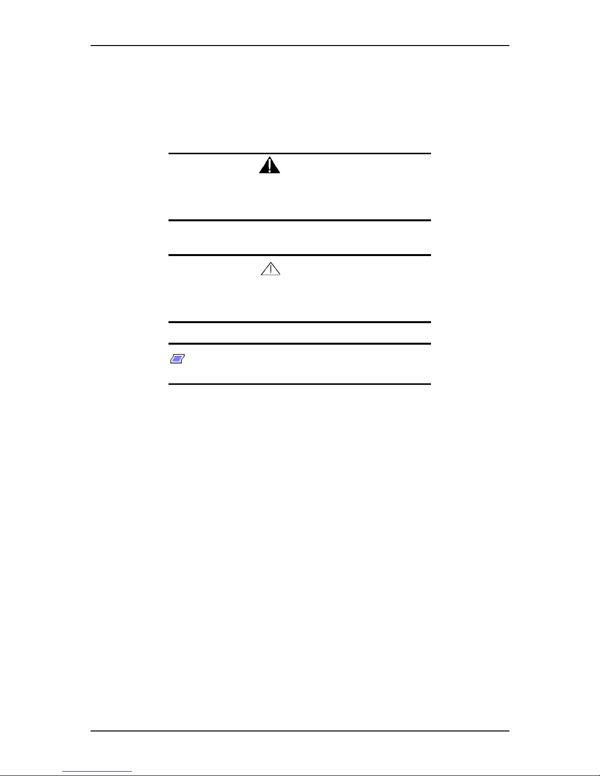
T ext Conventions
This guide uses the following text conventions.
Warnings, cautions, and notes have the following meanings:
Warning
Warnings alert you to situations that could result in serious personal injury or loss of life.
Caution
Cautions indicate situations that can damage the system hardware or software.
Notes: give important information about the material being
described.
■ Names of keyboard keys are printed as they appear on the keyboard. For example,
Ctrl, Alt, or Enter.
■ Text or keystrokes that you enter appear as boldface type. For example, type
abc123 and press ENTER.
■ File names are printed in upper case letters. For example, AUTOEXEC.BAT.
Page 11

User Guide
8
www.nec-computers.com
Safety Notices
Caution
To red uce th e risk of electric shock wh ich coul d caus e person al
injury, follow all the safety notices.
Symbols are shown in your documentation and on your
equipment to indicate safety hazards.
Regulatory Information
European Notice
Products with the CE marking comply with both the Electromagnetic Compatibility
Directive (89/336/EEC) and the Low Voltage Directive (73/23/EEC) - modified by the
Directive 93/68/EEC - issued by the Commission of the European Community.
Compliance with these directives implies conformity to the following European
Standards:
■ EN55022: Radio Frequency Interference
■ EN55024 (1998+A1:2001): Immunity characteristics
■ EN6100-3-2: Limits for harmonic current emissions
■ EN6100-3-3: Limitation of voltage fluctuation and flicker in low-voltage supply
system
■ EN60950-1 (2001): Product Safety
Warning
This is a Class A product. In domestic environment this product
may cause radio interference in which case the user may be
required to take adequate measures (EN5502 2).
If your system includes a telecommunication network board, the input/output socket is
classified as Telecommunication Network Voltage (TNV-3).
Page 12

User Guide
9
www.nec-computers.com
USA and Canada Notice
Products with UL marking comply with the following UL standards:
■ UL 1950 (3rd edition 1998)
Products with FCC marking comply with the following FCC standards
■ FCC part 15
The model type/ref. used for UL and FCC certification can be found on the regulatory
labels stuck on your system.
The equipment has been tested and found to comply with the limits for a Class A or B
digital device, pursuant to part 15 of the FCC rules. These limits are designed to
provide reasonable protection against harmful interference when the equipment is
operated in a commercial environment. This equipment generates, uses, and can radiate
radio frequency energy, and if not installed and used in accordance with the instruction
manual, may cause harmful interference to radio communications. Operation of this
equipment in a residential area is likely to cause harmful interference, in which case the
user will be required to correct the interference at his own expense.
Modifications to the Product
CE and FCC Marking
We cannot be held responsible for modifications made by the User and the
consequences thereof, which may alter the conformity of the product with the CE or
FCC Marking.
Connections and Remote Earths
PELV (Protected Extra Low Voltage)
To ensure the extra-low voltage integrity of the equipment, only connect equipment
with mains-protected electrically-compatible circuits to the external ports.
SELV (Safety Extra Low Voltage)
Every input and output of this product is classified as Safety Extra Low Voltage.
Remote Earths
To prevent electrical shock, connect all local (individual office) systems and system
support equipment to the same electrical circuit of the building wiring. If you are
unsure, check the building wiring to avoid remote earth conditions.
Building Supply
Only connect the equipment to a building supply that is in accordance with current
wiring regulations in your country. In the U.K., those are the IEE regulations.
Page 13

User Guide
10
www.nec-computers.com
Power Supply and Cables
Power Supply
■ The DC push-button on/off switch on the front panel does not turn off the system
AC power. +5vdc is present on the system board whenever the AC power cords are
connected between the system and an AC outlet. Before doing the procedures in
this manual, make sure that your system is powered off and unplug the AC power
cords from the back of the chassis. Failure to disconnect power before opening
your system can result in personal injury and equipment damage.
■ Under no circumstances should the user attempt to disassemble the power supply.
The power supply has no user-replaceable parts. Inside the power supply are hazardous voltages that can cause serious personal injury. A defective power supply
must be returned to your dealer.
Cables
■ In the U.S.A. and Canada, the power cord must be a UL-listed detachable power
cord (in Canada, CSA-certified), type ST or SJT, 16 AWG, 3-conductor, provided
with a moulded-on NEMA type 5-15 P plug cap at one end and a moulded-on cord
connector body at the other end. The cord length must not exceed 9 feet (2.7
meters).
■ Outside the U.S.A. and Canada, the plug must be rated for 250 VAC, 10 amp
minimum, and must display an international agency approval marking. The cord
must be suitable for use in the end-user country. Consult your de aler or the local
electrical authorities if you are unsure of the type of power cord to use in your
country. The voltage change occurs via a switch in the power supply.
■ The detachable power supply cords are intended to serve as the disconnect devices.
■ For PLUGGABLE EQUIPMENT, the socket-outlet shall be installed near the
equipment and shall be easily accessible.
■ This equipment has a 3-wire, grounded power cords. To prevent electrical hazards,
do not remove or defeat the ground prong on the power cords. Replace a power
cord if it gets damaged. Contact your dealer for an exact replacement.
Batteries
Lithium batteries can be dangerous. Improper handling of lithium batteries may result
in an explosion. Dispose of lithium batteries as required by local ordinance. Also see
“Product Disposal” on page 11
Chassis Cover Removal and Replacement
When servicing your system, make sure to replace the chassis cover and secure it with
the screws before plugging in the power cable and turning it on. The chassis cover
ensures proper airflow and cooling.
Page 14

User Guide
11
www.nec-computers.com
Laser Compliance Statement
The optical devices are tested and certified to be compliant with International Electrotechnical Commission IEC60825-1 and European EN60825-1 standards for Class 1
laser products.
Class 1 laser products are not considered hazardous. The optical devices are designed
such that there is never human access to laser radiation above a Class 1 level during
normal operation or prescribed maintenance conditions.
The optical devices installed in your system is designed for use solely as a component
of such electronic product and therefore does not comply with the appropriate
requirements of Code of Federal Regulation Sec. 1040.10 and Sec. 1040.11 for
COMPLETE laser products
Warning - Hazardous Voltage!
Hazardous voltage is present inside your system when it is connected to an AC supply
even when the system’s power switch is off. Exposure to Hazardous Voltage could
cause personal injury. To reduce the risk of electric shock which could cause personal
injury, follow all safety notices. The symbols shown are used in your documentation
and on your equipment to indicate safety hazards.
Warning -Avoid Electrostatic Discharge!
Circuit cards and integrated circuits can be easily damaged by static electricity. To
reduce risk of damage, store them in protective packaging whenever they are not
installed in your system.
Before you install or remove memory modules, video memory, disk drives, circuit
cards or other devices, protect them from static electricity. To do so, make sure your
system’s power switch is OFF. Then, unplug the system’s AC power cord(s). Wear an
anti-static wrist strap (available at electronic supplies stores) to handle the device you
want to install. Be sure to connect the wrist strap to an unpainted metal portion of the
system chassis.
As an alternative, you can dissipate electrostatic buildup by touching an unpainted
metal portion of the system chassis with one hand. Handle the device you are installing
with the other hand, and maintain continuous contact with the unpainted portion of the
chassis until it is installed in the system.
Product Disposal
The Wa ste Electrical and Electronic Equipment (WEEE) Directive
requires that used electrical and electronic products must be disposed of
separately from normal household waste in order to promote reuse,
recycling and other forms of recovery and to reduce the quantity of waste
to be eliminated with a view to reduce landfill. WEEE includes accessories
such as keyboard, mouse, remote control, speakers, etc. When you dispose of such
products, please follow the agreement made between you and us and/or your
distributor.
Page 15

User Guide
12
www.nec-computers.com
System Features
The WA2500/SA2500 system is a highly flexible and reliable system designed to offer
the highest levels of performance at an affordable price. It is:
■ based on the NVIDIA® CK8-04 Professional chipset,
■ designed for the AMD OpteronTM processors,
■ housed in a tower chassis that can also easily be installed into a standard EIA 19-
inch rack cabinet.
To get comfortable with your computer, take a tour around your system by reading the
sections hereafter.
Page 16

User Guide
13
www.nec-computers.com
Related Documents
In the EXPRESSBUILDER CD-ROM in which you found this User’s Guide, you can
also find several other documents relevant to your system, options and accessories.
Some printed documents may also have been shipped with your system.
We recommend you read these additional documents as it becomes necessary when
setting up, using or upgrading your system.
Page 17
User Guide
14
www.nec-computers.com
System Chassis Features
Front View
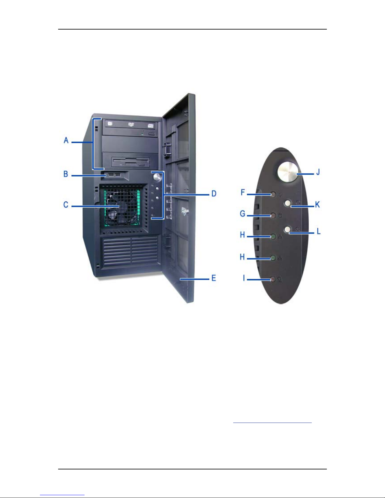
The following figure shows the location of the front system features
Figure 1: Front View
A 5.25-inch bays B USB ports
Four 5.25-inch bays, one of which may include a
tape backup unit, CD-ROM drive, DVD-ROM
drive, DVD-RW drive or COMBO DVD-ROM CDRW drive. A floppy disk drive can also be fitted
using a specific bracket.
Two Universal Serial Bus (USB) ports allow
you to connect USB-equipped peripheral
devices such as printers.
C H ard Disk s cage D Co ntrol LEDs an d buttons
Depending on your configuration, this cage either
contains SATA or SCSI drives, which can be hotswappable or fixed. The cage shown is a fixed
drives cage, featuring a frontal fan.
E Front door F Power LED
Refer to
“Status Indicators” on page 18 fo r
more information.
G Access LED H LAN LEDs 1 & 2
Front View Detail (D)
Page 18

User Guide
15
www.nec-computers.com
Refer to “Status Indicators” on page 18 for
more information.
Refer to “Status Indicators” on page 18 fo r
more information.
I
Fan Failure, Overheat and Power Supply
Failure LED
J
Power on/off button
Refer to
“Status Indicators” on page 18 for
more information.
Press this button to turn on/off the power.
Refer to the
“Powering On your System” on
page 86, “Powering Off your System” on
page 88, or “Forcing a Power Shutdown”
on page 89 sections for details.
K
Reset Button
L
Fan Failure, Overheat and Power Supply
Failure Button
Press this button to reboot the system. Press this button to stop the alarm that signals
a problem has been detected.
Page 19
User Guide
16
www.nec-computers.com
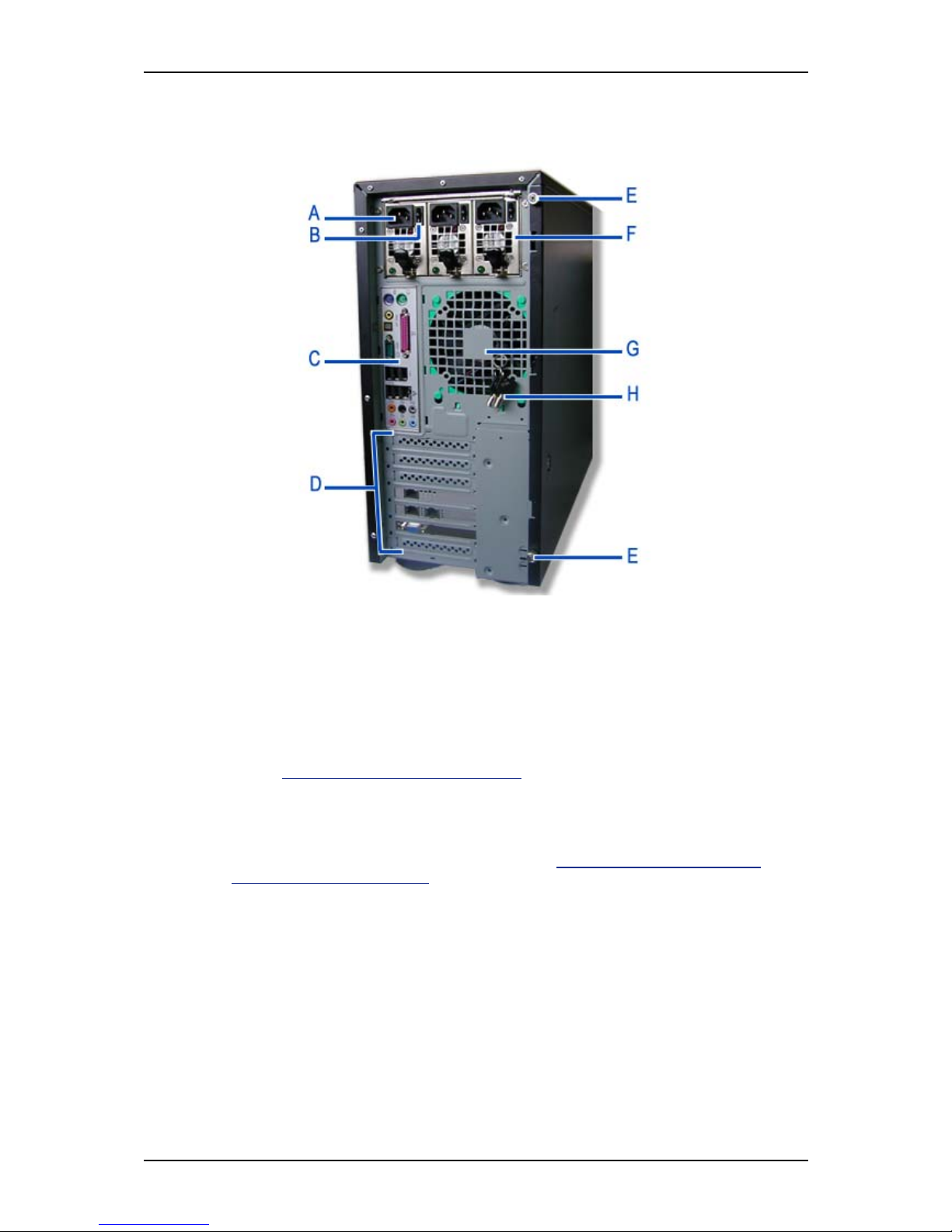
Rear View
Figure 2: Rear View
A AC power connector
Connect the power cord to this socket.
B Power switch
C Connectors
Refer to
“Back Panel Connectors” on page 24 for details.
D Expansion boards slots
Refer to the ‘Expansion Boards Slots’ section hererafter for details
E Thumbscrews
Remove the thumbscrews to remove the right side door.
See “Removing or Installing the
Right Side Door” on page 122.
F Power supply bay
Depending on your configuration, it is fitted with a fixed power supply, or one with hotswappable power modules (shown in the picture).
GFan
Keep the area near the venting holes clear for proper ventilation.
H Front panel and right side door ke ys
Page 20
User Guide
17
www.nec-computers.com
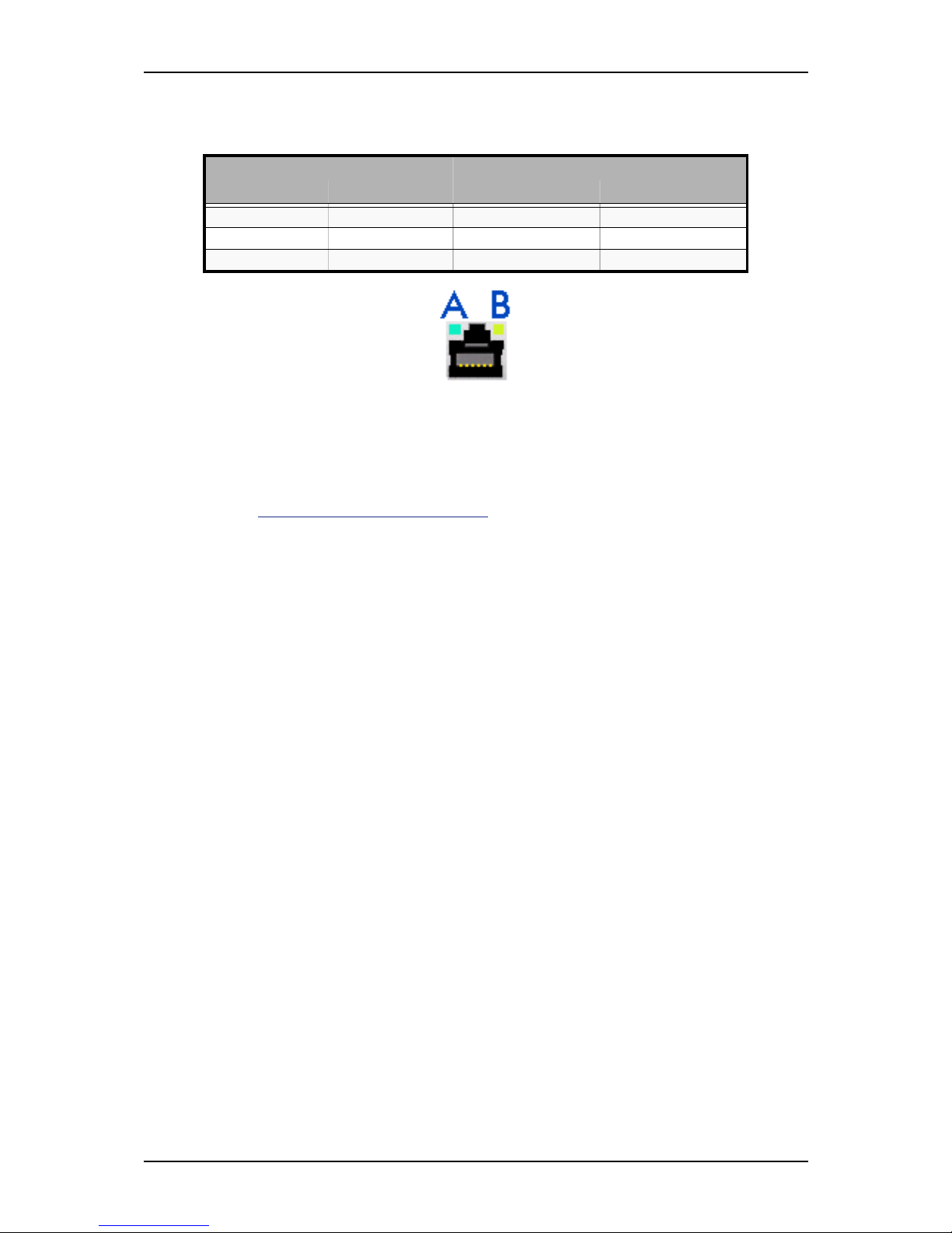
RJ45 Leds
Figure 3: RJ45 Leds
Expansion Board Slots
Two PCI expansion slots, one PCI-E x16 expansion slot and one PCI-E x1 expansion
slot are available, enabling you to install additional Video Boards and LAN boards.
Refer to “Optional Features” on page 29 for details about the components that may be
installed in the expansion slots.
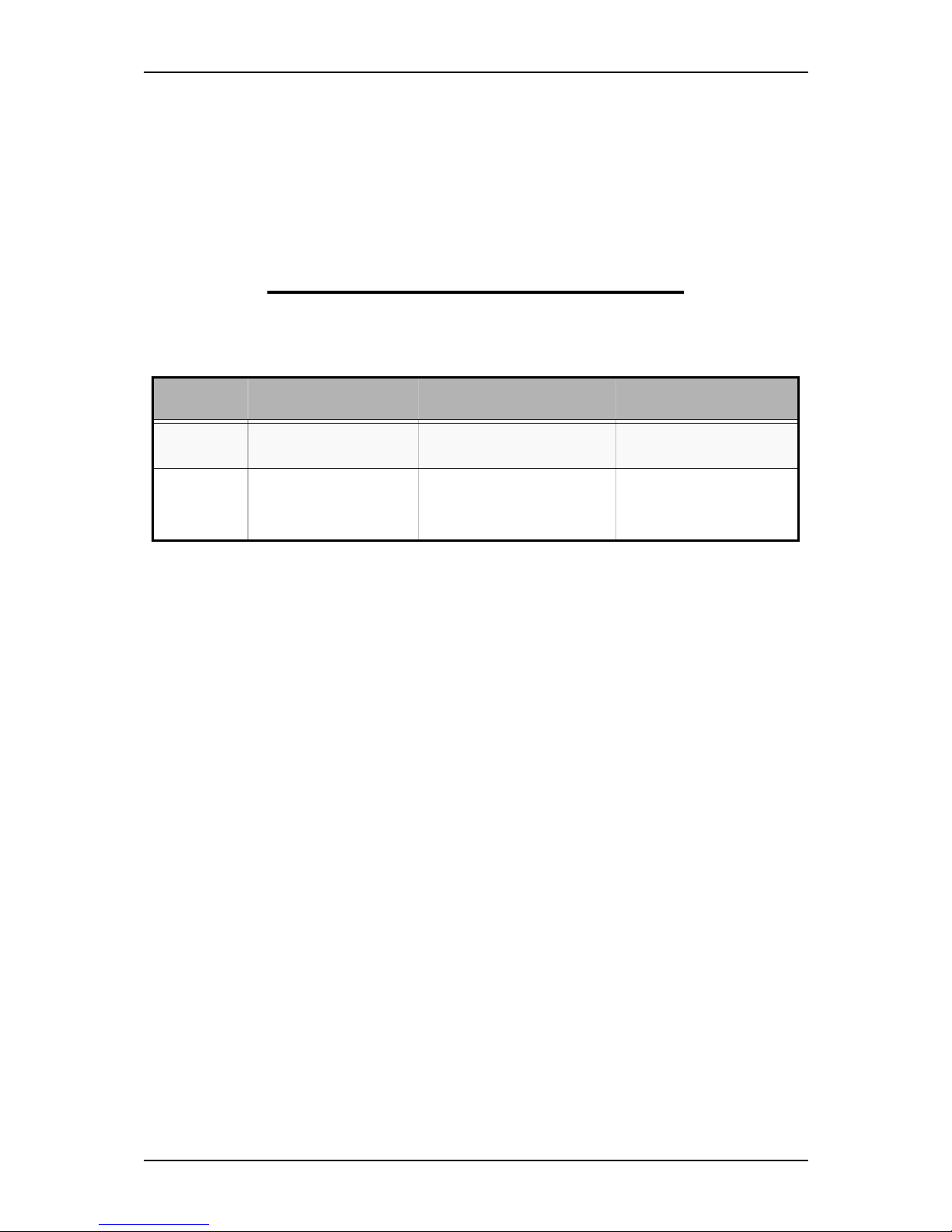
Table 1: RJ45 Leds Activity
ACT/LINK LED (A) SPEED LED (B)
Status Description Status Description
OFF No link OFF 10 Mbps connection
GREEN Linked ORANGE 100 Mbps connection
BLINKING Data activity GREEN 1 Gbps connection
Page 21
User Guide
18
www.nec-computers.com
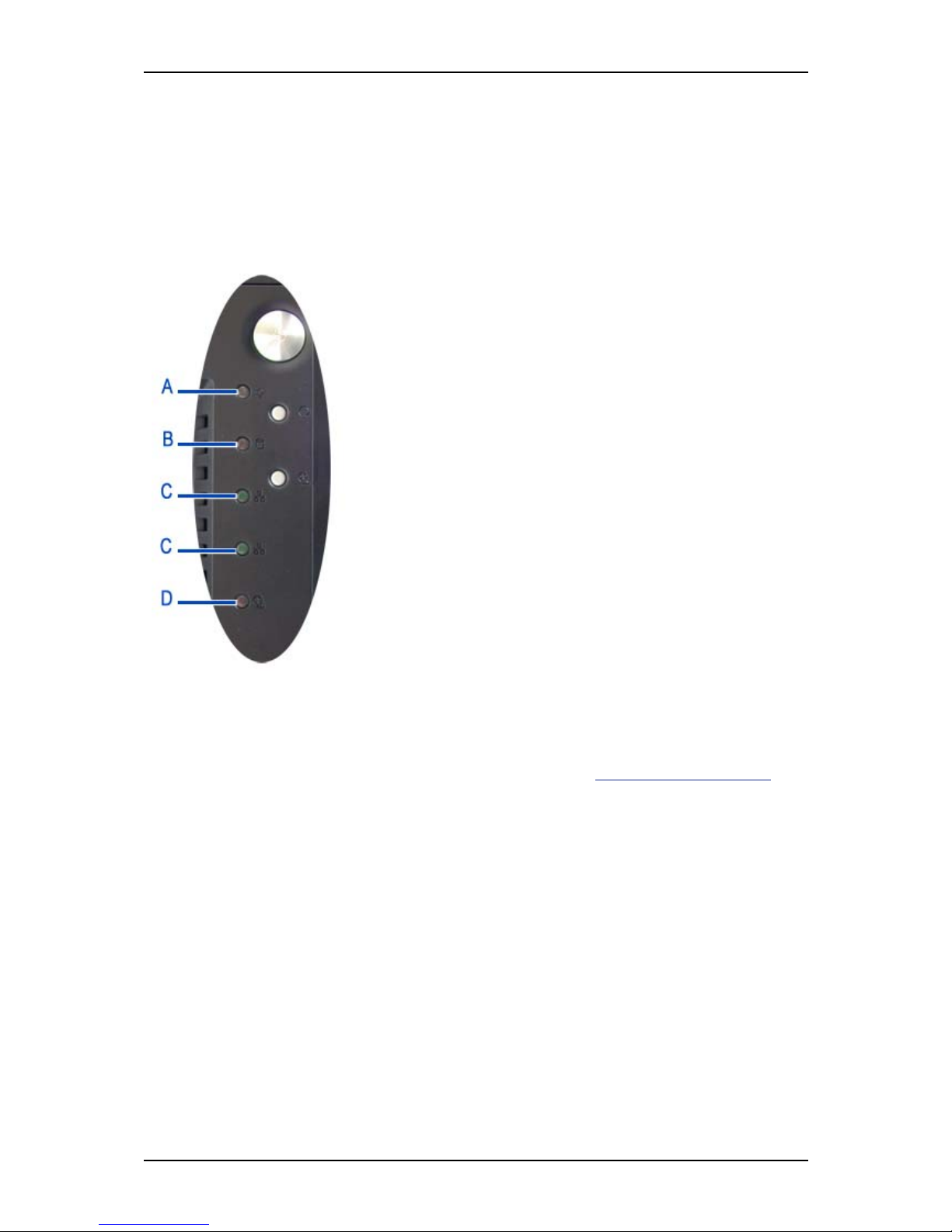
St atus Indicators
This section explains the indication and meanings of the system lamps located on the
front and back panels of your system.
Front Panel
Power ON Lamp (A)
■ Lights green to indicate normal operation with the system
powered on.
■ Remains off when the system is powered off.
■ Blinks green when the system is in a power-saving mode.
Access Lamp (B)
Lights amber when one of the drives (on-board S-ATA or IDE)
is being accessed.
LAN 1 & 2 Activity Lamps (C)
These LEDs are not used.
Fan Failure, Overheat and Power Supply Failure LED (D)
■ Lights red when a fan, overheating or power supply failure
is detected.
■ Turns off automatically once the problem is corrected.
Back Panel
RJ45 Ports Activity Lamps
Refer to the back panel description for more details. See “RJ45 Leds” on page 17.
Power Supply LEDs (Hot-Swap Power Supply Only)
The LEDs are lit green when the power module is functioning correctly. If one of the
LEDs is off, change the corresponding power module or check that the power cables
are correctly plugged in.
Page 22
User Guide
19
www.nec-computers.com
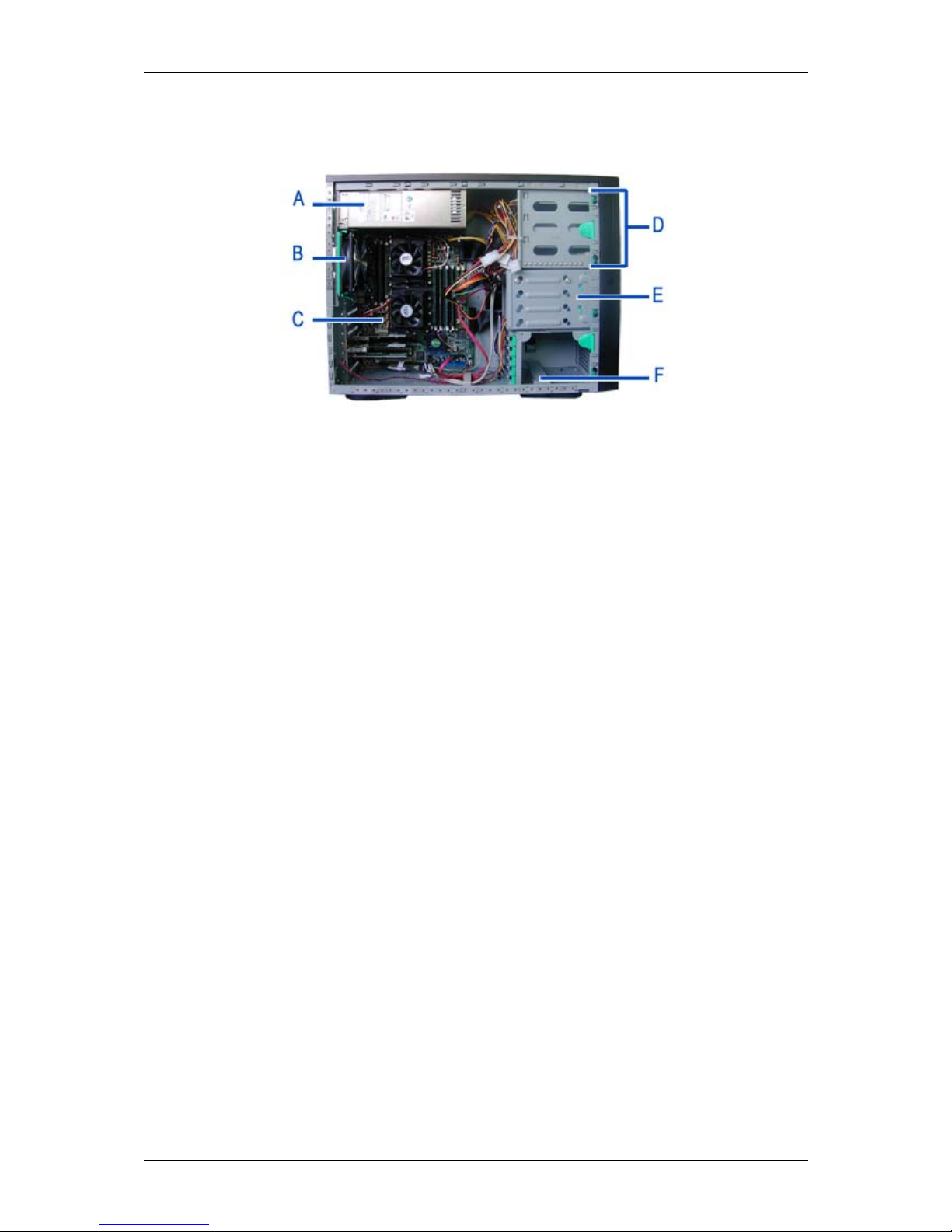
Internal View
Figure 4: Internal View
A Power supply slot
B Fan (depending on your configuration)
C Motherboard
D 5.25-inch devices slots
E Hard disk drives slots
F Fan slot (depending on your configuration)
Page 23
User Guide
20
www.nec-computers.com
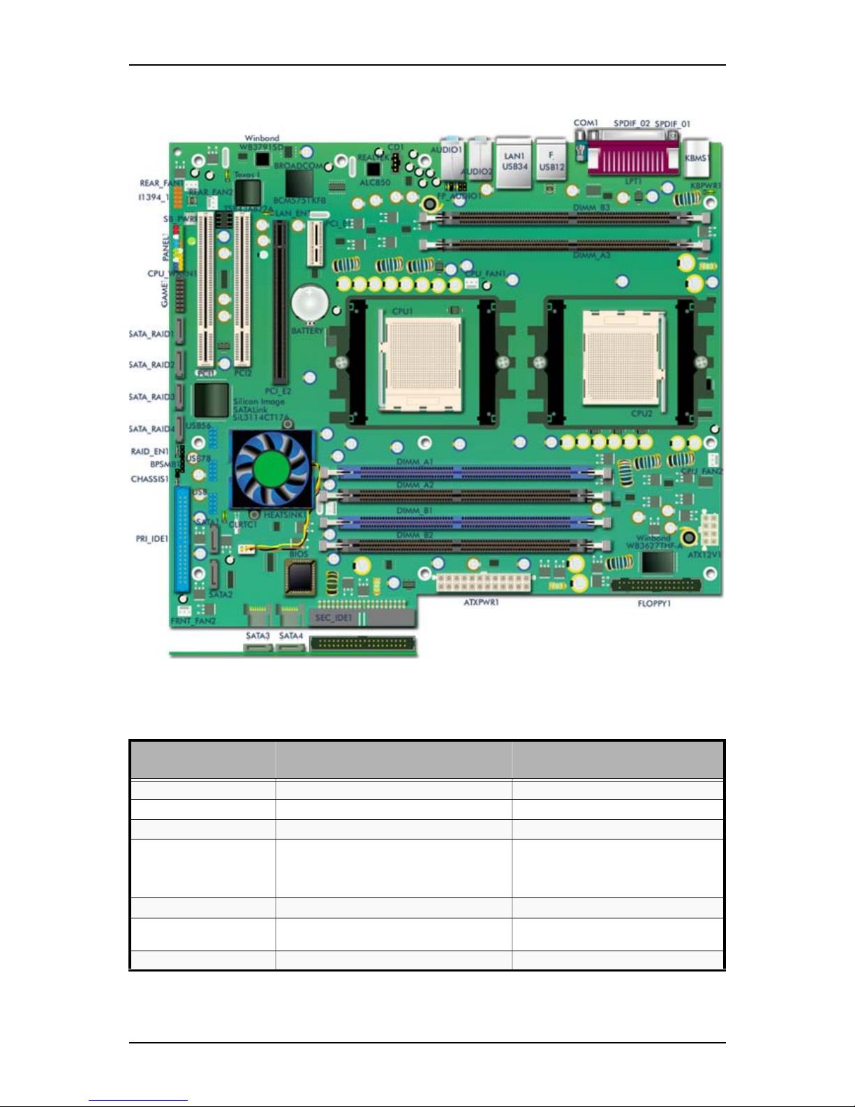
Motherboard
Figure 5: SA2500/WA2500 Motherboard
Table 2: SA2500/WA2500 Motherboard Internal Connectors
Denomination on
drawing
Name Type
REAR_FAN1 Rear fan1 connector 3 pin header (white)
REAR_FAN2 Rear fan2 connector 3 pin header (white)
I1394_1 Connects to the front panel IEEE1394 port 10 pin header (orange)
SB_PWR Standby power LED (lights up to indicate
that the system is on, in sleep mode or
soft-off mode). Always unplug the power
cord before working on the motherboard.
Standard LED
PANEL1 Front Panel connector 10 pin header (multi coloured)
CPU_WARN1 CPU warning LED (lights up to indicate that
CPU1 is not properly installed).
Standard LED
GAME1 GAME/MIDI port connector 16 pin header
Page 24

User Guide
21
www.nec-computers.com
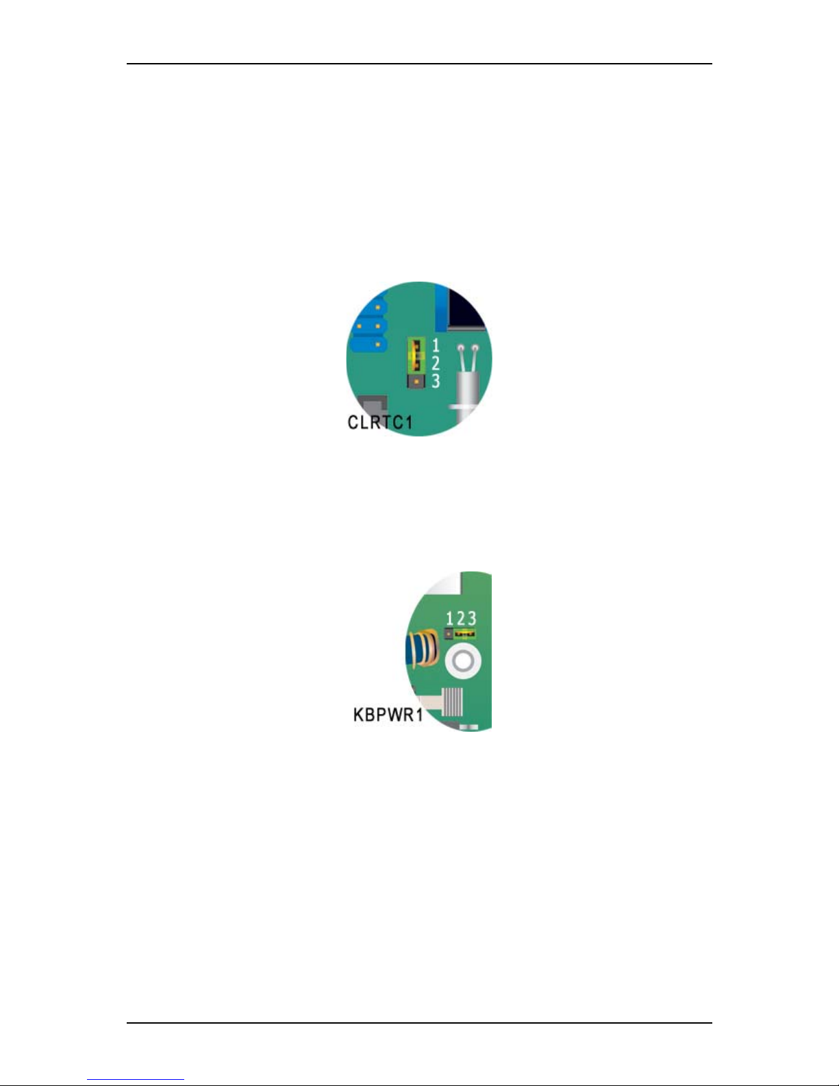
Configuring MotherBoard Jumpers
Clear CMOS Jumper (CLRTC1)
1. Power off the system and unplug the AC power cord.
SATA_RAID1,
SATA_RAID2,
SATA_RAID3,
SATA_RAID4
Connect to the SATA RAID hard disk drives
(when the on-board RAID controller is
active)
7 pin header
RAID_EN1 RAID controller jumper (not used) 3 pin
USB56, USB78, USB USB connectors 10 pin connector
BPSMB1 Connects to the Backplane SMBus
connector
6 pin connector
CHASSIS1 Connects to the chassis intrusion switch 4 pin connector
PRI_IDE1 Primary IDE connector 40 pin connector
SEC_IDE1 Secondary IDE connector 40 pin con nector
SATA1, SATA2, SATA3,
SATA4
Connect to the SATA hard disk drives 3 pin header
FRNT_FAN1 Used for the chipset fan 3 pin header (white)
FRNT_FAN2 Front fan2 connector 3 pin header (white)
CLRTC1 Clear RTC RAM jumper 3 pin header
HEATSINK1 not used
PCI1, PCI2 PCI connectors Standard PCI expansion slots
PCI_E2 PCI-E 16x connector PCI Express expansion slot (black)
LAN1_EN1 GB LAN controller setting 3 pin connector
PCI_E1 PCI-E 1x connector PCI Express expansion slot (white)
BATTERY Battery socket
CD1 CD-ROM audio line in 4 pin header (black)
FP_AUDIO1 Connects to the front panel audio 10 pin header (black)
CPU_FAN1 CPU1 fan connector 3 pin header (white)
DIMM_A1, DIMM_A2,
DIMM_B1, DIMM_B2
DDR sockets (linked to CPU1) 184 pin standard sockets
DIMM_A3, DIMM_B3 DDR sockets (linked to CPU2) 184 pin standard sockets
CPU1 CPU connector Socket 94 0
CPU2 CPU connector Socket 940
KBPWR1 Keyboard power jumper 3 pin connector
CPU_FAN2 CPU2 fan connector 3 pin header (white)
ATXPWR1 Power connector 24 pin keyed connector
FLOPPY1 Floppy Disk Drive connector 34 pin header
ATX12V1 Auxiliary Power connector 8 pin keyed connector
Table 2: SA2500/W A2500 Motherboard Internal Connectors (Continued)
Denomination on
drawing
Name Type
Page 25
User Guide
22
www.nec-computers.com
2. Remove the onboard battery.
3. Set position as 2-3 (Clear CMOS).
4. Wait 5 to 10 seconds.
5. Set position as 1-2 (Normal [Default]).
6. Re-install the battery.
7. Plug the power cord and power on the system. The message ‘CMOS checksum
bad’ displays.
8. Press DEL to enter the BIOS Setup, reload the default settings (or make any
changes that you judge necessary), save and reboot your system.
Figure 6: Clear CMOS Jumper
Wake Up using Keyboard (KBPWR1)
Set this jumper to enable or disable the keyboard wake up feature. If it is set to 2-3,
pressing a key on the keyboard will wake up the system. (Check that this feature is also
enabled in the BIOS Setup utility).
Figure 7: Wake Up using Keyboard Jumper
, ,
Page 26
User Guide
23
www.nec-computers.com
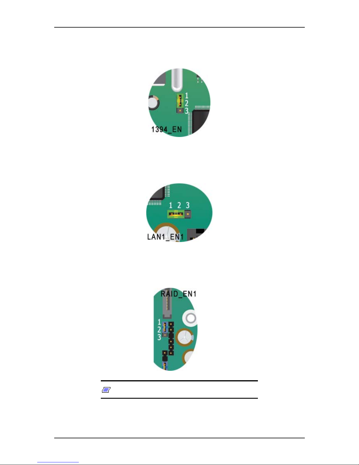
1394 Controller Setting (1394_EN1)
This jumper allows you to enable or disable the onboard IEEE controller. Set to pins 12 to activate the controller.
Gigabit LAN Controller Setting (LAN1_EN1)
This jumper allows you to enable or disable the onboard 1 Gigabit LAN controller. Set
to pins 1-2 to activate the controller.
RAID Controller Setting (RAID_EN1)
This jumper allows you to enable or disable the onboard RAID controller. Set to pins 12 to activate the controller.
Note: this RAID chipset is not used on the system.
Page 27
User Guide
24
www.nec-computers.com
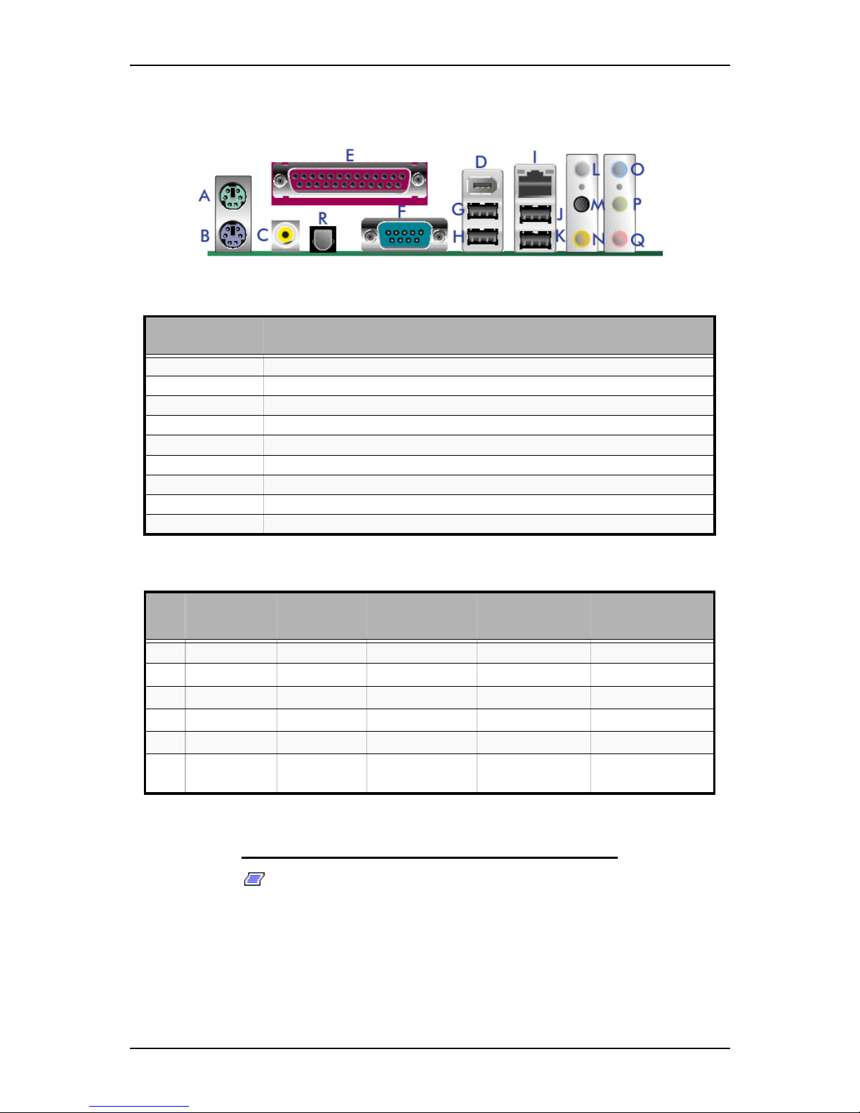
Back Panel Connectors
Memory Configuration
Notes:
■ In dual-channel configuration, the total size of the memory
modules installed per channel must be the same.
- Single CPU:
DIMM_A1 + DIMM_A2 = DIMM_B1 + DIMM_B2
Table 3: Back Panel Connectors
Denomination
on drawing
Description
A Mouse P/S2 connector
B Keyboard P/S2 connector
C Optical S/PDIF Port
D IEEE Port
E Parallel Port
F Serial Port
G, H, J, K USB Ports
I RJ-45 Ports
R Coaxial S/PDIF Port
Table 4: Audio 2, 4, 6 or 8-channels configuration
Port Headset
2-channels
4-channels 6-channels 8-channels
O
Light Blue Line In Line In Line In Line In
P
Lime Line out Front Speaker out Front Speaker out Front Speaker out
Q
Pink Mic In Mic In Mic In Mic In
M
Black - Rear Speaker Out Rear Speaker Out Rear Speaker Out
L
Gray - - - Side Speaker Out
N
Yellow
Orange
- - Center/Subwoofer Center/Subwoofer
s
Page 28
User Guide
25
www.nec-computers.com
- Dual CPU:
DIMM_A1 + DIMM_A2 = DIMM_B1 + DIMM_B2 =
DIMM_A3 + DIMM_B3
■ For optimal performances, the memory capacity for CPU2
(Slots A3 + B3) must be equal to the CPU1 memory capacity
(Slots A1+ A2 + B1 + B2.)
■ Always install memory modules approved by the system’s
manufacturer. Contact your sales representative for more
information.
Table 5: Memory Configuration
Number of
CPUs
2 memory modules
installed in
4 memory modules
installed in
6 memory modules
installed in
1 CPU A1 + B1 A1 + B1
A2 + B2
not possible
2 CPUs A1 + B1 A1 + B1
A3 + B3
A1 + B1
A2 + B2
A3 + B3
Page 29

User Guide
26
www.nec-computers.com
St andard Features
■ On-board LAN
■ Dual channel memory architecture support
■ SCSI and S-ATA hard disk drives support
■ CD-ROM, DVD-ROM, COMBO DVD-ROM/ CD-RW, DVD+R9 (DL) support
■ PCI support
■ PCI-E x16 video boards support
■ PCI-E x1 LAN board support
■ 5.25-inch tape backup unit support
Processor
The system board accommodates two AMD OpteronTM processors with 1 MB L2
cache.
Memory
The system board contains six 184-pins DIMM slots each supporting DDR 400 ECC
memory. You may install a minimum of 512 MB and as much as 12 GB (2 x 6GB).
Your system supports dual-channel memory architecture. Refer to “Memory
Configuration” on page 24 for details.
PCI Slots
The motherboard features two standard PCI expansion slots.
PCI -Express Slots
■ One PCI-E x16 expansion slot (for a video or LAN board, for instance).
■ One PCI-E x1 expansion slot (for a LAN board, for instance).
Network Controller
Note: To ensure EMC product regulation compliance, the
system must be used with a shielded LAN cable.
The motherboard features the Broadcom BMC5751 Gigabit PCI-E LAN controller:
■ Integrated 10/100/1000BASE-T transceiver
- 10/100/1000BASE-T triple-speed MAC
- SMBus 2.0 controller
Page 30

User Guide
27
www.nec-computers.com
- On-chip voltage regulation
- Wake-On-LAN power switching circuit
■ PCI Express host interface
■ Wake-On-LAN
RAID Controller
The motherboard features the NVIDIA® nForce4® PRO controller:
■ Allows RAID 0, RAID 1, RAID 0+1, and JBOD configuration for 4 SATA connectors.
ACPI
The motherboard supports the Advanced Configuration and Power Interface (ACPI) as
defined by the ACPI 2.0 specifications. An ACPI aware operating system can put the
system into a state where the hard drives spin down, the system fans stop, and all
processing is halted. However, the power supply will still be on and the processors will
still be dissipating some power, so the power supply fans will still run.
The system board supports sleep states s0, s1, s3, s4, and s5:
■ s0: Normal running state.
■ s1: Processor sleep state. No context will be lost in this state and the processor
caches will maintain coherency.
■ s3: Suspend to RAM. Your working environment is Saved To RAM.
■ s4: Hibernate. Your working environment is Saved To Disk
■ s5: Shutdown.
Keyboard and Mouse
The keyboard/mouse controller is PS/2-compatible.
Peripheral Bays
Your system features three 5.25-inch bays that you can use with either a hard disk
drive, an optical device such as a CD-ROM, DVD-ROM, a COMBO DVD-ROM CDRW, a DVD+R9 (DL) or a tape backup unit.
You can also use one of these bays to install a Floppy Disk Drive using a special
bracket.
Page 31

User Guide
28
www.nec-computers.com
Peripheral Bays
The system supports a variety of standard PC AT-compatible peripheral devices. The
chassis includes these peripheral bays:
■ Three 5.25-inch file bays for installing half-height 5.25-inch peripheral devices
such as optional tape drives (An optical drive is factory-installed).
■ The hard disk drive bays for installing up to four S-ATA or SCSI hard disk drives.
Page 32

User Guide
29
www.nec-computers.com
Optional Features
You will find hereafter information about the optional components that may be
installed in your system.
This is not an exhaustive list, some options may not be available any more, others may
have been added.
Page 33

User Guide
30
www.nec-computers.com
CD-ROM Drive
■ High Speed CD: 48X max.
■ Buffer: 128 kBytes
■ Emergency Eject: Pin-hole on front panel to release tray.
■ Software Ejection/ Loading and Volume Control
■ Form Factor: 5.25" half height.
■ Compatibility: Mixed mode CD-ROM disc, CD-DA, Photo-CD Multi-session,
CD-ROM XA, CD-I Ready, CD-Plus, CD-Extra, CD-RW.
■ Transfer rate (max): 7200Kbytes/s
■ CD-ROM ATA Interface (burst):
- 16.6 Mbytes/s (PIO Mode 4/ MULTI word DMA Mode 2)
■ Rotation Speed: approx.10500 rpm
■ Full Stroke Access Time: 75 ms (typical)
■ Environmental Specifications:
Table 6: CD-ROM Drive Environmental Specifications
Operating Non-operation
Temperature 0°C to 50°C -40°C to +60°C
Humidity (% relative humidity) 10% to 80% 5% to 90%
Vibration 0.35 G (10-500 Hz) 2.0 G (10-500 Hz)
Page 34

User Guide
31
www.nec-computers.com
DVD-ROM Drive
■ High Speed DVD: 16X max & High Speed CD: 40X max.
■ Buffer: 256 kBytes
■ Emergency Eject: Pin-hole on front panel to release tray.
■ Software Ejection/ Loading and Volume Control
■ Form Factor: 5.25" half height.
■ Compatibility: DVD-ROM (single-layered and dual-layered), DVD-R 3.95GB &
4.7GB, DVD+R, DVD-RW (rev 1.0 & 1.1), DVD+RW, DVD-RAM 2.6GB & 4.7
GB, CD-ROM Mode1 and Mode2 data disc, CD-R,CD-RW,CD-ROM XA, CD-I,
Photo-CD Multi-session, CD-Extra, CD TEXT, CD Audio disc, Mixed mode CDROM disc.
■ Transfer rate (max):
- CD-ROM: 6000Kbytes/s
- DVD-ROM: 22.1 Mbytes/s
■ CD-ROM ATA Interface (burst):
- 16.6 Mbytes/s (PIO Mode 4/ MULTI word DMA Mode 2)
- 8.3 Mbytes/s (Single word DMA Mode 2)
- 66.7 Mbytes/s (Ultra DMA Mode 4)
■ Rotation Speed:
- CD-ROM: 8780 rpm
- DVD-ROM: 9420 rpm
■ Full Stroke:
- CD-ROM: 160 ms
- DVD-ROM: 180 ms
■ Environmental Specifications:
Table 7: DVD-ROM Drive Environmental Specifications
Operating Non-operation
Temperature 5°C to 45°C -40°C to +60°C
Humidity (% relative humidity) 15% to 85% 10% to 90%
Vibration 0.25 G (zero to peak) 50 G (zero to peak)
Page 35

User Guide
32
www.nec-computers.com
DVD +R9 Combination Drive
■ Emergency Eject: Pin-hole on front panel to release tray.
■ Form Factor: 5.25" half height
■ Enhanced IDE Interface
■ Multifunction device:
■ Data buffer: 2MB
■ Compatibility:
- Reads data in each CD-ROM, CD-ROM XA, CD-I, Video CD, CD-Extra, CD-
Text, Photo CD (Single and Multi session), DVD-ROM, DVD-R(Ver.1.0, Ver.
2.0 for Authoring), CD-DA
- Reads and writes CD-Audio, CD-R, CD-RW, DVD-R (Ver. 2.0), DVD-RW,
DVD+R and DVD+RW
■ Access time (max):
- CD-ROM: 200ms
- DVD-ROM: 230ms
■ Performance:
■ Environmental Specifications:
Table 8: Combo Drive Performance
Reading Speed Writing Speed
CD-ROM 48x
CD-R 48x 48x
DVD 16x (single layer)
12x (dual layer)
CD-RW 40x 32x
DVD+R 16x 16x
DVD-R 16x 16x
DVD-R-DL 4x
DVD+R-DL 7x 4x
DVD+RW 12x 8x
Table 9: Combo Drive Environmental Specifications
Operating Non-operation
Temperature 5°C to 45°C -30°C to +60°C
Humidity (% relative humidity) 15% to 80% 15% to 95%
Vibration 0.30 G (5-500 Hz) 2.0 G (5-50 0 Hz)
Page 36

User Guide
33
www.nec-computers.com
DVD+R9 (DL) Drive
■ Manual Load/Eject Button
■ Drive State and Single LED Specification (green)
■ Form Factor: 5.25" half height
■ Enhanced IDE Interface
■ Multifunction device:
- 48x CD-ROM Reader
- 24x CD-RW Writer (for high speed CD-RW)
- 16x DVD reader
- 4x DVD+R-DL/16x DVD-R/4x DVD-RW/16x DVD+R/4x DVD+RW
■ Data buffer: 2MB
■ Compatibility:
- Reads data in each CD-Audio(8cm/12cm), CD-ROM (mode 1 and mode 2),
CD-ROM XA (mode 2, form 1 and form 2), Photo CD (single or multiple sessions), CD-I(FMV), Video CD, CD Extra., CD-TEXT
- Writes CD-Audio(8cm/12cm), CD-ROM (mode 1 and mode 2), CD-ROM XA
(mode 2, form 1 and form 2), Photo CD (single or multiple sessions), CDI(FMV), Video CD, CD Extra., CD-TEXT
■ Transfer rate:
Table 10: DVD+R9 (DL) Transfer rate
Write Read
DVD+R
16x CAV 9 - 22 Mbytes/sec
13x CAV 7.3 - 17.5MBytes/sec
12xZCLV 8.2 - 16.6Mbytes/sec
8x ZCLV 5.5 -11MBytes/sec
6x ZCLV 5.5-8.2MBytes/sec
4x CLV 5.5 MBytes/sec
2.4x CLV 3.3 MBytes/sec
DVD-ROM
Single Layer 6.6-16x CAV 9-22 Mbytes/sec
Dual Layer 3-7x CAV 4.1-10 Mbytes/sec
DVD-R/+R
6.6-16x CAV 9-22 Mbytes/sec
DVD+R-DL
2-5x CAV 2.7-6.9 Mbytes/sec
DVD+R-DL
4x CLV 5.5 MBytes/sec
2.4x CLV 3.3 MBytes/sec
DVD+RW/-RW
3.3-8x CAV 4.5-11 Mbytes/sec
DVD+RW
4x CLV 5.5 MBytes/sec
2.4x CLV 3.3 MBytes/sec
DVD-Video with CSS protection
2-5x CAV 2.7-6.9 Mbytes/sec
DVD-R
16x CAV 9 – 22 MBytes/sec
13x CAV 7.3 – 17.5 MBytes/sec
12x ZCLV 8.2 – 16.6 MBytes/sec
8x ZCLV 5.5 -11 MBytes/sec
6x ZCLV 5.5-8.2 MBytes/sec
4x CLV 5.5 MBytes/sec
2x CLV 2.7 MBytes/sec
CD-ROM/CD-R
Mode 1 and Mode 2 Form 1 (2048 Bytes)
20-48x CAV 3000 - 7200 kBytes/sec
CD-RW
Mode 1 and Mode 2 Form 1 (2048 Bytes)
13-32x CAV 1950 - 4800 kBytes/sec
Page 37

User Guide
34
www.nec-computers.com
DVD-RW
4x CLV 5.5 MBytes/sec
2x CLV 2.7 MBytes/sec
1x CLV 1.3 8 MByt es/ sec
DAE
13-32x CAV 1950 - 4800 kBytes/sec
CD-R
48x CAV 3000-7200kBytes/sec
48x ZCLV 3000-7200kBytes/sec
40x CAV 2550-6000kBytes/sec
40x ZCLV 3000-6000kBytes/sec
32x PCAV 2550-4800kBytes/sec
32x ZCLV 3000-4800kBytes/sec
24x PCAV 2550-3600kBytes/sec
24x ZCLV 3000-3600kBytes/sec
16x CLV 2400kBytes/sec
8x CLV 1200kBytes/sec
Mode 2 and Mode 2 Form2
8x CLV 1200 kBytes/sec
CD-RW
24x ZCLV 3000-3600kBytes/sec
16x CLV 2400kBytes/sec
10xCLV 1500kBytes/sec
4xCLV 600kBytes/s ec
Table 10: DVD+R9 (DL) Transfer rate
Write Read
Page 38

User Guide
35
www.nec-computers.com
DA T72 Tape Backup Unit (SCSI)
Please refer to the documentation on the Tape Online CD for more information.
Page 39

User Guide
36
www.nec-computers.com
Sony AIT -1 Turbo Backup Unit (IDE)
Please refer to the documentation on the Tape Online CD for more information.
Page 40

User Guide
37
www.nec-computers.com
Sony AIT -2 Turbo Backup Unit
Please refer to the documentation on the Tape Online CD for more information.
Page 41

User Guide
38
www.nec-computers.com
L T O 2 T ape Drive (SCSI)
Please refer to the documentation on the Tape Online CD for more information.
Page 42

User Guide
39
www.nec-computers.com
DA T40 Tape Backup Unit (USB)
Please refer to the documentation on the Tape Online CD for more information.
Page 43

User Guide
40
www.nec-computers.com
PCI-E x1 Syskonnect LAN Board
(one RJ-45 port)
■ Bus interface:
- PCI-Express 1.0a compliant
- x1 PCI-Express Serial Link (adapter can also be operated in x4, x8 and x16
Slots)
- PCI-Express Native Hot Plug according to PCI-Express 1.0a and Advanced
Configuration
■ IEEE Standard
■ 10/100/1000BASE-T
■ Full height bracket
■ TCP, UDP and IP checksum calculation
■ Jumbo frames support
■ TCP segmentation
■ Dynamic Interrupt Moderation
■ Promiscuous Mode/ Multicast support
■ Alert Standard Format (ASF)
■ PXE/ RPL support
■ Advanced Power Management/ Wake on LAN
■ Link Aggregation
■ Redundant Switch Failover
■ PCI Express Hot-Plug
■ Parity
■ Virtual LAN (VLAN) support
■ Virtual Cable TesterTM (VCT)
Page 44

User Guide
41
www.nec-computers.com
PCI-E x4 Syskonnect LAN Board
(two RJ-45 ports)
■ Bus interface:
- PCI-Express 1.0a compliant
- x4 PCI-Express Serial Link (adapter can also be operated in x8 and x16 Slots)
- PCI-Express Native Hot Plug according to PCI-Express 1.0a and Advanced
Configuration
■ IEEE Standard
■ 10/100/1000BASE-T
■ Full height bracket
■ TCP, UDP and IP checksum calculation
■ Jumbo frames support
■ TCP segmentation
■ Dynamic Interrupt Moderation
■ Promiscuous Mode/ Multicast support
■ Alert Standard Format (ASF)
■ PXE/ RPL support
■ Advanced Power Management/ Wake on LAN
■ Link Aggregation
■ Redundant Switch Failover
■ PCI Express Hot-Plug
■ Parity
■ Virtual LAN (VLAN) support
■ Virtual Cable Tester
TM
(VCT)
Page 45

User Guide
42
www.nec-computers.com
S-A TA Hard Disk Drive
■ Capacity: 80GB minimum
■ 7200RPM
■ RAID 0, RAID 1, RAID 5 and RAID 0+1 support
Caution
You may use either S-ATA or SCSI hard disk drives. However,
mixing S-ATA and SCSI hard disk drives is not supported.
S-ATA Hard Disk Drives Cage
■ The hard disk drive bays for installing up to four S-ATA hard disk drives.
Page 46

User Guide
43
www.nec-computers.com
SCSI Hard Disk Drive
■ Capacity: 73GB minimum
■ 10000 or 15000 RPM
■ RAID 0, RAID 1, RAID 5 and RAID 0+1 support
Caution
You may use either S-ATA or SCSI hard disk drives. However,
mixing S-ATA and SCSI hard disk drives is not supported.
SCSI Hard Disk Drives Cage
■ The hard disk drive bays for installing up to four SCSI hard disk drives.
Page 47

User Guide
44
www.nec-computers.com
A TI-RageXL PCI V ideo Board
■ Memory configuration: 8MB
■ Bus specifications: PCI bus/ PCI 2.2
■ Output: CRT
■ Resolution support:
- 2D/3D resolution: 1600x1200 max
- Color depth: 16,7M colors max
Page 48

User Guide
45
www.nec-computers.com
nVidia Quadro NVS280/285 PCI-E x16
Video Board
The NVIDIA Quadro NVS 280 PCI is a 64 MB DDR SDRAM, graphics add-in card
that delivers professional 2D workstation performance and integrated features of the
NVIDIA Quadro NVS 280 Graphics Processor Unit (GPU).
Utilizing the advanced nView software, the NVIDIA Quadro NVS 280 PCI delivers
next-generation multi-monitor capabilities through its dual integrated 350 MHz
RAMDACs that deliver up to 2048 x1536 at 75Hz, 32bpp on each display and up to a
maximum digital resolution of 1600x1200 @ 60Hz.
Key Features and Benefits
■ NVIDIA nView™ Multi-Display Software
Sets a new standard in workstation productivity by delivering unprecedented
stability, image quality and performance. No other solution features rock-solid
stability with productivity-enhancing functionality, all seamlessly integrated into
the Windows environment.
■ Dual 350MHz Ramdacs
Deliver crystal-clear image quality.
■ Integrated TMDs Transmitters
Enable support for the latest digital flat panel displays.
■ High-Density Connectors
Provide flexible support for a variety of display types from analog to digital.
■ Low-Profile From Factor
Enables support for small form-factor systems.
■ Unified Driver Architecture
Provides easy installation and manageability through a single unified driver for
large scale system deployment.
Product Features
■ Support for multiple displays (various configurations of VGA and DVI-I) enhanced multi-display productivity is powered by dual RAMDACs and
NVIDIA's patented nView multi-display software.
■ NVIDIA Unified Driver Architecture - enables ease of use in administering and
maintaining networks of graphics workstations.
■ Certification on more workstation applications than any competing technology means more robust user experiences and higher performance.
Page 49

User Guide
46
www.nec-computers.com
■ Maximum resolution of 2048x1535 per VGA screen - enables higher levels of
details and increase productivity.
Maximum resolution over digital port: 1600 x 1200 at 60Hz.
Page 50

User Guide
47
www.nec-computers.com
nVidia Quadro FX 540 PCI-E x16 V ideo Board
Designed for entry-level professional 3D applications, the NVIDIA Quadro FX 540,
featuring a HDTV 10-pin connector, deliver features and value without compromising
on quality, precision, performance, and programmability.
The NVIDIA Quadro FX entry-level GPUs provide advanced features and benefits
found in the Quadro FX family, ranging from a 128-bit floating point graphics pipeline
and 12-bit subpixel precision, to Quadro memory management and many more.
Enabled by the NVIDIA gold-standard Unified Driver Architecture (UDA), the
NVIDIA Quadro FX 540 by PNY is certified on a wide set of CAD, DCC, and
scientific visualization applications, offering the value and capabilities workstation
users expect.
Key Features and Benefits
■ Proven Workstation Graphics Architecture
Parallel vertex engines, programmable pixe l pipelines, and workstation specific
features result in the industry's highest application performance and quality.
■ Advanced Vertex and Pixel Programmability
Enables real-time shaders to simulate a wide range of physical effects and surface
properties.
■ Full 128-bit Precision Graphics Pipeline
Enables mathematical computations to maintain high accuracy, resulting in
unmatched visual quality.
■ 12-bit Subpixel Precision
12-bit subpixel precision delivers high geometric accuracy, eliminating spreckles,
cracks, and other rasterization anomalies.
■ PCI Express Support
Designed specifically to take advantage of the next-generation PCI Express bus
architecture. This new bus doubles the bandwidth of AGP 8X delivering over 4 GB
per second in both upstream and downstream data transfers.
■ Unified Driver Architecture
Provides easy installation and manageability through a single unified driver for
large scale system deployment. The performance and power of the NVIDIA
Quadro FX are built on a solid foundation of quality engineering.
Specifications
Graphics Processing Unit
■ Full 128-bit floating-point precision pipeline
■ 12-bit subpixel precision
Page 51

User Guide
48
www.nec-computers.com
■ 8 pixels per clock rendering engine
■ Hardware accelerated anti aliased points and lines
■ Hardware OpenGL overlay planes
■ Hardware accelerated two-sided lighting
■ Hardware accelerated clipping planes
■ 3rd-generation occlusion culling
■ 16 textures per pixel
■ Hardware-Accelerated Pixel Read-Back
Next Generation Shading Architecture
■ Fully programmable GPU (OpenGL 1.5/DirectX 9.0 class)
■ Long fragment and vertex programs (up to 65,536 instructions)
■ Looping and subroutines (up to 256 loops per vertex program)
■ Dynamic flow control
■ Conditional execution
High-Level Shader Languages
■ Optimized compilers for Cg, OpenGL shading language, and Microsoft HLSL
■ OpenGL 1.5 and DirectX 9.0 support
■ Open source compiler
Architecture
■ x16 PCI-Express
■ 128MB high-speed DDR frame buffer
■ 128-bit IEEE floating-point precision graphics pipeline
■ 128-bit color
■ 32-bit floating point frame buffer
■ 12-bit subpixel precision
Memory
■ High-speed memory (128MB GDDR3)
■ Advanced compression algorithms (color and Z data)
Page 52

User Guide
49
www.nec-computers.com
nVidia Quadro FX1400 PCI-E x16 V ideo Board
The NVIDIA Quadro® FX 1400 provides the best blend of quality, precision,
performance and programmability for all professional 3D applications.
The NVIDIA Quadro FX architecture takes application performance to new levels by
featuring an array of parallel vertex engines, a radically new line engine and fully
programmable pixel pipelines coupled to a high-speed graphics DRAM bus.
Pipeline efficiency is further multiplied by NVIDIA's next-generation crossbar
memory architecture, enabling occlusion-culling, depth Z-buffer, and color
compression.
Key Features and Benefits
■ Proven Workstation Graphics Architecture
Parallel vertex engines, programmable pixe l pipelines, and workstation specific
features result in the industry's highest application performance and quality.
■ Advanced Vertex and Pixel Programmability
Enables real-time shaders to simulate a wide range of physical effects and surface
properties.
■ Full 128-bit Precision Graphics Pipeline
Enables mathematical computations to maintain high accuracy, resulting in
unmatched visual quality.
■ 12-bit Subpixel Precision
12-bit subpixel precision delivers high geometric accuracy, eliminating spreckles,
cracks, and other rasterization anomalies.
■ High Quality Full-Scene Anti aliasing (FSAA)
Up to 16x FSAA dramatically reduces visual aliasing artifacts or "jaggies" at
resolutions up to 3840x2400, resulting in highly realistic scenes.
■ PCI Express Support
Designed specifically to take advantage of the next-generation PCI Express bus
architecture. This new bus doubles the bandwidth of AGP 8X delivering over 4 GB
per second in both upstream and downstream data transfers.
■ Unified Driver Architecture
Provides easy installation and manageability through a single unified driver for
large scale system deployment. The performance and power of the NVIDIA
Quadro FX are built on a solid foundation of quality engineering.
Specifications
Graphics Processing Unit
■ Full 128-bit floating-point precision pipeline
Page 53

User Guide
50
www.nec-computers.com
■ 12-bit subpixel precision
■ 8 pixels per clock rendering engine
■ Hardware accelerated anti aliased points and lines
■ Hardware OpenGL overlay planes
■ Hardware accelerated two-sided lighting
■ Hardware accelerated clipping planes
■ 3rd-generation occlusion culling
■ 16 textures per pixel
■ OpenGL quad-buffered stereo (3-pin sync connector)
■ Hardware-Accelerated Pixel Read-Back
Architecture
■ x16 PCI-Express
■ 128MB high-speed DDR frame buffer
■ 128-bit IEEE floating-point precision graphics pipeline
■ 128-bit color
■ 32-bit floating point frame buffer
■ 12-bit subpixel precision
■ Unlimited programmability
■ 3D volumetric textures
■ Single-system powerwall
Shading Architecture
■ Fully programmable GPU (OpenGL 1.5/DirectX 9.0 class)
■ Long fragment and vertex programs (up to 65,536 instructions)
■ Looping and subroutines (up to 256 loops per vertex program)
■ Dynamic flow control
■ Conditional execution
High-resolution Anti-aliasing
■ Up to 16x Full-Scene Anti-aliasing (FSAA)
■ Up to 2048x1536 per display or 3840x2400 for single digital display
■ 12-bit subpixel sampling precision enhances AA quality
■ Rotated grid FSAA significantly increases color accuracy and visual quality for
edges, while maintaining performance
Page 54

User Guide
51
www.nec-computers.com
Memory
■ High-speed memory (128MB GDDR3)
■ Advanced lossless compression algorithms (color and Z data)
Page 55

User Guide
52
www.nec-computers.com
nVidia Quadro FX3400/3450 PCI-E x16 V ideo
Board
Featuring the industry’s first top-to-bottom family of PCI Express™ products targeted
for professional CAD, DCC, and Scientific applications, NVIDIA Quadro FX ushers in
a new era of unprecedented performance, programmability, precision and quality.
The NVIDIA Quadro FX architecture takes application performance to new levels by
featuring an array of parallel vertex engines, a radically new line engine and fully
programmable pixel pipelines coupled to a high-speed graphics DRAM bus.
Pipeline efficiency is further multiplied by NVIDIA’s next-generation crossbar
memory architecture, enabling occlusion-culling, depth Z-buffer, and color
compression.
Key Features and Benefits
Proven Workstation Graphics Architecture
Parallel vertex engines, programmable pixel pipelines, and workstation specific
features result in the industry's highest application performance and quality.
Advanced Vertex and Pixel Programmability
Enables real-time shaders to simulate a wide range of physical effects and surface
properties.
Full 128-bit Precision Graphics Pipeline
Enables mathematical computations to maintain high accuracy, resulting in unmatched
visual quality.
12-bit Subpixel Precision
12-bit subpixel precision delivers high geometric accuracy, eliminating spreckles,
cracks, and other rasterization anomalies.
High Quality Rotated Grid Full-Scene Anti aliasing
Up to 16x FSAA dramatically reduces visual aliasing artifacts or "jaggies" at
resolutions up to 3840x2400, resulting in highly realistic scenes. New Rotated Grid
FSAA (RGFSAA) delivers unprecedented quality and performance.
High Precision Dynamic Range Imaging (HDPR) Technology
Sets new standards for image clarity and quality through floating point capabilities in
shading, filtering, texturing and blending. Enables unprecedented rendered image
quality for visual effects processing. Support for 32-bit floating point precision per
component - an industry exclusive.
Page 56

User Guide
53
www.nec-computers.com
Hardware Accelerated Pixel Read-Back
Greater than 1.0GB/sec pixel read-back performance delivers massive host throughput,
more than 5x the performance of previous generation graphics systems.
PCI Express Support
Designed specifically to take advantage of the next-generation PCI Express bus
architecture. This new bus doubles the bandwidth of AGP 8X delivering over 4 GB per
second in both upstream and downstream data transfers.
Unified Driver Architecture
Provides easy installation and manageability through a single unified driver for large
scale system deployment. The performance and power of the NVIDIA Quadro FX are
built on a solid foundation of quality engineering.
Specifications
Graphics Processing Unit
■ Full 128-bit floating-point precision pipeline
■ 12-bit subpixel precision
■ 8 pixels per clock rendering engine
■ Hardware accelerated anti aliased points and lines
■ Hardware OpenGL overlay planes
■ Hardware accelerated two-sided lighting
■ Hardware accelerated clipping planes
■ 3rd-generation occlusion culling
■ 16 textures per pixel
■ OpenGL quad-buffered stereo (3-pin sync connector)
■ Hardware-Accelerated Pixel Read-Back
Architecture
■ x16 PCI-Express
■ 256MB high-speed GDDR3 frame buffer
■ 128-bit IEEE floating-point precision graphics pipeline
■ 128-bit color
■ 32-bit floating point frame buffer
■ 12-bit subpixel precision
■ Up to 16x FSAA
■ Unlimited programmability
Page 57

User Guide
54
www.nec-computers.com
■ 3D volumetric textures
■ Single-system powerwall
Next Generation Shading Architecture
■ Fully programmable GPU (OpenGL 1.5/DirectX 9.0 class)
■ Long fragment and vertex programs (up to 65,536 instructions)
■ Looping and subroutines (up to 256 loops per vertex program)
■ Dynamic flow control
Memory
■ High-speed memory (256MB GDDR3)
■ Advanced lossless compression algorithms (color and Z data)
Page 58

User Guide
55
www.nec-computers.com
nVidia Quadro FX4500 PCI-E x16 V ideo Board
The NVIDIA Quadro® FX 4500 sets a new bar for workstation graphics, shattering the
limits of performance, programmability, precision, and quality for professional CAD,
DCC, and scientific applications.
The NVIDIA Quadro ultra-high end GPUs feature a revolutionary new architecture
with twice the geometry and fill rate, 5 times the hardware pixel read-back
performance and support up to 512MB ultra-fast GDDR3 memory.
Implementation of rotated-grid FSAA introduces far greater sophistication in the multisampling pattern, significantly increasing color accuracy and the visual quality of
edges and lines without compromising performance.
Key Features and Benefits
Performance: Highest Workstation Application Performance
Next-generation architecture enables over 2x improvement in geometry and fill rates
with the industry’s highest performance for professional CAD, DCC, and scientific
applications.
Precision: NVIDIA High-Precision Dynamic-Range (HPDR) Technology
HPDR sets new standards for image clarity and quality through floating point
capabilities in shading, filtering, texturing, and blending. Enables unprecedented
rendered image quality for visual effects processing.
Programmability: Next-Generation Vertex & Pixel Programmability
NVIDIA Quadro FX 4000 GPUs introduce infinite length vertex programs and
dynamic flow control, removing the previous limits on complexity and structure of
shader programs. With full support for Vertex and Shader Model 3.0, NVIDIA Quadro
FX 4000 GPUs deliver sophisticated effects never before imagined for real-time
graphics systems.
Quality: Rotated-Grid Full-Scene Antialiasing (FSAA)
The rotated-grid FSAA sampling algorithm introduces far greater sophistication in the
sampling pattern, significantly increasing color accuracy and visual quality for edges
and lines, reducing “jaggies” while maintaining performance.
Specifications
Memory
■ Size: 512MB
■ Interface: 256-bit
■ Type: GDDR3
■ Graphics Memory Bandwidth: 33.6GB/sec.
Page 59

User Guide
56
www.nec-computers.com
Architecture
■ x16 PCI-Express
■ 256MB high-speed GDDR3 frame buffer
3D Primitive Performances
■ Shader model: 3.0
■ Dual-Link DVI: Yes (2)
■ SLI support: Yes
■ Geometry (triangles per second): 150 million
■ Fill rate (texels per second): 5.1 billion
Connectors
■ DVI-I
■ DVI-I+Stereo
Page 60

User Guide
57
www.nec-computers.com
Promise FastT rack SX4100
Highlights
■ Four-port Serial ATA RAID controller with 1.5Gb/s per channel
■ Support for RAID levels 0, 1, 10, 5 and JBOD
■ Next generation RAID Engine, with multiple logical drive support
■ Low-profile form factor, ideal for 1U/2U systems
■ User friendly Web-based Promise Array Management Software (WebPAM™)
■ PerfectRAID™ technology for robust error handling and recovery of fatal, media
and disk errors
■ 32-Bit/66MHz PCI 2.2 interface
■ Online array expansion and RAID level migration to add capacity as needed
■ Supports hot swap of failed drives
■ Automatic/manual rebuild of hot spare drive
■ 64MB of onboard ECC cache memory
The Price/Performance Leader
For companies running popular applications like web services, file/email servers, video
streaming, NAS storage and nearline storage, the FastTrak SX4100 opens the world of
professional RAID 5 performance and data protection and combines it with costeffective Serial ATA (SATA) drives for the ultimate internal storage solution.
Improved RAS Functions with Serial ATA Drives
Designed specifically for Serial ATA RAID, the FastTrak SX4100 incorporates highly
desired features that are ideally suited for SATA storage demands and improving
overall RAS (Reliability, Availability and Serviceability).
In addition to an improved RAID algorithm, among the enhancements are multiple
logical drive support, Media Patrol™ and read check table. Equipped with the new
Promise Array Manager (WebPAM™) software, FastTrak SX4100 is extremely easy
to manage through a web graphical user interface.
Hardware-Assisted RAID 5 Architecture
RAID 5 implementation involves striping data and parity information (XOR) across the
storage array. Since those parity calculations are so processor-intensive, RAID 5
controllers traditionally require a dedicated CPU to perform the XOR calculations and
manage the array.
Instead of adding a costly CPU to the controller, Promise's FastTrak SX4100 uses an
integrated XOR engine for parity calculations, delivering extraordinary performance at
a dramatically lower price. This approach takes advantage of today's ultra-powerful PC
CPUs to manage the array and outperform traditional RAID 5 solutions.
Page 61

User Guide
58
www.nec-computers.com
Sophisticated Array Monitoring Tools
Web-based Promise Array Management (WebPAM) software offers professional
management tools in a simple-to-use, straightforward format. Array configurations,
management and monitoring features are available via the web based interface.
Moreover, the FastTrak SX family supports industry standard SNMP so third party
management application integration is simplified.
Specifications
Controller Specifications
■ Four SATA ports at 1.5Gb/s (150 MB/sec)
■ Supports up to 1.6 terabytes of storage per controller (with four 400GB drives)
■ Dual controller support within a system
■ Low profile form factor ideal for 1U/2U systems
■ 32-Bit, 66 MHz PCI bus; PCI 2.2 compliant
■ Promise RAID Processor with integrated XOR engine for RAID parity
calculations and memory controller for local cache memory
■ 64MB onboard ECC cache memory
■ FRAM for RAID5 transaction log to avoid data corruption in the event of
application hangs
■ Built-in GPIO ports for enclosure management
RAID Levels Supported
■ RAID 5: Striped parity on 3-4 drives, ultimate data protection, capacity and
performance balance
■ RAID 10: Data mirrored then striped across four drives, for double drive failure
protection
■ RAID 1: Mirrored pairs of drives for data protection with increased read
performance
■ RAID 0: Data striped across 2-4 drives for increased performance but no data
protection
■ JBOD: Just a Bunch Of Drives: independent connected drives with no RAID interconnection
RAID Fault Tolerance and Robustness Features
■ Multiple logical drive support enables combining different RAID levels on one set
of disks
■ Online array expansion and RAID level migration to add capacity as needed
■ PerfectRAID™ technology for error handling and recovery of fatal media and disk
errors
Page 62

User Guide
59
www.nec-computers.com
■ Read Check table to avoid data read errors
■ Support hot swap of failed drives and hot spare
■ Automatic/manual rebuild of hot spare drive
■ Background initialization for instant drive availability
■ Background rebuild, migration and synchronization
■ Error and event logging
■ Variable stripe block size support to meet various application requirements
■ Optimal disk utilization with gigabyte rounding
■ Support for SMART capable drives
■ Synchronization can be scheduled periodically for RAID array data consistency
Advanced Performance Features
■ Multiple caching policy support:
■ Write-back:
- Write-back cache for maximum write performance
- Write-through: Write-through cache for data protection in the event of applica-
tion freeze
- Read ahead: Predictive read ahead caching based on application and data types
■ Packet commands and interrupt coalescing minimize interrupts for better
performance
■ Elevator seek streamlines commands based on where data is located on the disk
■ Load balancing (mirrored RAID array only)
- Web-Based Promise Array Management
■ Creates, deletes, expands, and converts disk arrays remotely
■ Array synchronization and rebuild scheduling
■ Monitors drive, array, and enclosure status and provides online event logging
■ E-mail notification of disk, array, controller or enclosure events (e.g. error or
degrade conditions)
Page 63

User Guide
60
www.nec-computers.com
Adaptec SCSI Card 29160ALP
The Adaptec SCSI Card 29160 delivers the maximum throughput for a single channel
Ultra160 SCSI card by using a 64-bit PCI interface.
The Adaptec SCSI Card 29160 provides the ideal connection to Ultra160 SCSI (LVD)
hard disks and devices (internally and externally) and legacy devices (internally).
Highlights
■ 160 MByte/sec performance
■ SpeedFlex technology ensures top performance of all connected devices,
regardless of SCSI generation
■ Seamless backwards compatibility protects legacy devices
■ Industry-leading compatibility, reliability*
■ CRC (Cyclical Redundancy Checking) improves data integrity
■ Domain Validation intelligently verifies system configuration for improved reli-
ability
Specifications
■ 1-channel, 64-bit (32-bit compatible), ideal for internal and external hard disk
drive configurations
■ Data Transfer Rate: 160MB/sec
■ External Connectors
- One 68-pin for LVD SCSI devices
■ Internal Connectors
- One 68-pin for LVD SCSI
- One 68-pin for Ultra Wide SCSI
- One 50-pin for Ultra SCSI Bus Type 64-bit PCI (32-bit compatible)
■ Board Dimensions 6.87" x 3.87"
Page 64

User Guide
61
www.nec-computers.com
Adaptec SCSI Card 29320ALP
Highlights
■ Adaptec Seamless Streaming® ; this technology pushes the performance of
Ultra320 SCSI to its theoretical limit by implementing in hardware three new
design advances:
- Ultra Streaming Data Path
- Matrix Command Management
- Rapid Packet Protocol Engine
■ 320 MByte/sec performance per channel
■ Industry-leading compatibility and reliability
Specifications
■ Hardware Features
- 64-bit/ 133 MHz PCI/PCI-X interface
- Compatible with 32-bit PCI slots (thus running in the slower 32-bit mode)
- Single-channel Ultra320 SCSI card.
■ Connectors
- 68-pin internal connector
- 68-pin VHDCI external connector for Ultra320 SCSI (LVD) hard disks drives
■ Physical Specifications
- Size: 16,8cm x 6,4cm
Page 65

User Guide
62
www.nec-computers.com
SCSI Card SecuRAID 1 14
Highlights
With support for 64-bit addressing and a full RAID feature set, the SecuRAID 114
delivers unsurpassed data throughput and fault tolerance for your mid-range server or
performance workstation.
Designed around LSI Logic's next-generation I/O technology - Fusion-MPT™- the
SecuRAID 114 leverages a streamlined firmware-level programming interface and
advanced hardware designs to offer unequalled I/O efficiency and performance. The
SecuRAID 114 also incorporates a space-saving MD2 (low-profile PCI) form factor,
increasing available space, even in the most limited server and workstation enclosures.
■ One single-channel LSI53C1020 Ultra320 SCSI controller
■ IA-64 ready
■ Intel GC80302 integrated I/O processor
■ 64-bit, 66 MHz PCI
■ PCI 2.2 compliant
■ Integrated 64 MB ECC SDRAM cache memory
■ Advanced management and configuration utilities
■ Supports up to 40 logical drives per controller
■ Auto resume during array reconstruction
■ Background initialization for Quick RAID 5 setup
■ FlexRAID®:
- Online capacity expansion
- Online RAID level migration
Features
■ Disk Array Features
- Supports RAID0/RAID1/RAID5/RAID10/RAID50
- Supports up to 40 logical drives
- Supports hot-swap of failed drives
- Automatic rebuild of hot spare drives
- Auto resume on array reconstruction
■ Hardware Features
- 64-bit / 66MHz PCI interface compliant to PCI Rev2.2
- A 64MB cache memory is soldered on the card.
Page 66

User Guide
63
www.nec-computers.com
- Single-channel, PCI RAID controller card with an Ultra 320 SCSI interface
- Modes supported: SE or LVD mode, SCSI FAST, ULTRA, ULTRA2, 160M
and 320M
■ Connectors:
- one internal 68-pin
- one external VHDCI-68-pin connector
■ Physical & Environmental Specifications
- Size: 16,76 x 6,45 cm
- Operating temperature: up to 55°C
- Voltage: 5V± 0.25V
Page 67

User Guide
64
www.nec-computers.com
Promise FastT rack S150 SX4
Highlights
■ Four-port Serial ATA RAID controller with 1.5Gbps per channel.
■ 32-Bit/66MHz PCI 2.2 interface.
■ Support for RAID level 0, 1, 10, 5 and JBOD.
■ Online array expansion and RAID level migration to add capacity on the fly.
■ Supports hot swap of failed drives.
■ Automatic/manual rebuild of hot spare drive.
■ PerfectRAID technology for robust error handling and recovery of fatal, media and
disk errors.
■ Variable stripe block size support enables optimization for diverse application
requirements.
■ Supports up to 256MB of SDRAM memory.
Maximize RAID Performance with Serial ATA Drives
The FastTrak S150 SX4 is designed for RAID-perfect Serial ATA. Serial ATA is an
evolutionary replacement for the Parallel ATA physical storage interface. The Serial
ATA standard incorporates highly anticipated features that are ideally suited for ATA
RAID use such as:
- Thinner Serial ATA cables up to one meter long to provide flexible rout-
ing and better airflow.
- No jumper setting is required.
- Point-to-point configuration to support one drive per cable and achieve
performance scalability.
- Higher availability with hot pluggable drive support.
- Enhanced reliability with CRC error checking on all protocol phases.
Promise Hardware-Assisted RAID 5 Architecture
RAID 5 implementation involves striping data and parity information (XOR) across the
storage array. Since those parity calculations are so processor-intensive, RAID 5
controllers traditionally require a dedicated CPU to perform the XOR calculations and
manage the array.
Instead of adding a costly CPU to the controller, Promise's FastTrak S150 SX4
controller uses an integrated XOR engine for parity calculations, delivering
extraordinary performance at a lower price.
Page 68

User Guide
65
www.nec-computers.com
Sophisticated Array Monitoring Tools
Promise Array Management (PAM) software offers professional management tools in a
simple-to-use, straightforward format. Array configurations, management and
monitoring features are available via the windows based management and can be
access locally or via the TCP/IP network remotely. Moreover, the FastTrak SX family
supports industry standard SNMP so third party management application integration is
simplified.
Specifications
■ Controller Specifications
- Four SATA ports at 1.5Gpbs (150 MB/sec)
- Storage capacity up to 1 terabyte per controller (with four 250 GB drives)
- 32-Bit, 66 MHz PCI bus; PCI 2.2 compliant
- Promise RAID Processor with XOR engine for RAID parity calculations and
memory controller for local cache memory
- Controller cache: 168-pin DIMM slot supports up to 256MB of ECC or non-
ECC SDRAM memory (min. 64MB required). Memory not included.
- FRAM for RAID5 transaction log to avoid data corruption in the event of appli-
cation hangs
- Built-in GPIO ports for enclosure management
■ RAID Fault Tolerance and Robustness Features
- Online array expansion and RAID level migration to add capacity on the fly.
- PerfectRAID technology for error handling and recovery of fatal, media and
disk errors.
- DRM (Drive Roaming Metadata) technology; supports drive roaming to any
port on the controller, and allows array roaming in the event of controller failure.
- Support hot swap of failed drives.
- Automatic/manual rebuild of hot spare drive.
- Background initialization for instant drive availability.
- Background rebuild, migration and synchronization.
- Error and event logging.
- Variable stripe block size support to meet various application requirements.
- Optimal disk utilization with gigabyte rounding.
- Support for SMART capable drives.
- Synchronization can be scheduled periodically for RAID array data consistency .
Page 69

User Guide
66
www.nec-computers.com
■ Advanced Performance Features
- Multiple caching policy support:
- Write-back (maximum write performance) and write-through (data pro-
tection in the event of application freeze).
- Predictive read ahead caching based on application and data types.
- Packet commands and interrupt coalescing minimize interrupts for better per-
formance.
- Elevator seek streamlines commands based on where data is located on the disk
- Load balancing (mirrored RAID array only).
■ Promise Array Management
- Creates, deletes, expands, and converts disk arrays remotely
- Array synchronization and rebuild scheduling
- Displays drive and array status
- Monitors enclosure status and provides online event logging
- E-mail notification of disk, array, controller or enclosure events (e.g. error or
degrade conditions)
Page 70

User Guide
67
www.nec-computers.com
Setting Up Your System
This chapter describes how to select a site, unpack the system, make cable connections,
and power on the system units. Information on front and rear panel features, switches
and LEDs are also included in this chapter.
Page 71

User Guide
68
www.nec-computers.com
Setting Up Y our Server (Rack)
This chapter describes how to select a site, unpack the system, make cable connections,
and power on the system units. Information on front and rear panel features, switches
and LEDs are also included in this chapter.
Setup Flow.
Selecting t
Select a suitable site for the server. Assemble the 19-inch rack assembly.
Unpack the server and accessories from the shipping carton box.
Install the server into the rack assembly.
Connect peripheral devices to the server.
Connect the power cord to the server.
Power on the server to start software setups. Setups depend on the optional internal devices installed and
the peripheral devices connected.
If no operating system was factory-installed, install one to the server.
Install the utilities in the provided EXPRESSBUILDER CD-ROM.
Making backup copie
After all the system setup procedures are completed, make backup copies of system information.
System information is required for recovering the server from the trouble or after replacing the system
board.
Page 72

User Guide
69
www.nec-computers.com
Selecting Server Site
To use the server, install it on a standard EIA 19-inch rack assembly.
Refer to the documentation attached to the rack or contact your sales agent for the
installation of the server on the rack.
Warning
Observe the following instructions to use the server safely. Failure to
follow these instructions may result in death or serious personal injury.
See “General Safety Information” on page 119 for details.
■ Do not use the server in any unapproved place.
■ Do not connect the ground line to a gas pipe.
Caution
Observe the following instructions to use the server safely. Failure to
follow these instructions may cause a fire, personal injury, or property
damage. See “General Safety Information” on page 119 for
details.
■ Do not carry or install the server only by a single person.
■ Do not install the server where the load may be concen-
trated on a specific point.
■ Do not install any component on the server only by a single
person.
■ Do not pull out a device from the rack if the rack is unstable.
■ Do not leave more than one device being pulled out from the
rack.
■ Do not provide the wiring exceeding the rating power.
Do not install the rack in the places listed below. Installing the rack or mounting the
server on the rack in such a place may cause some malfunction to occur.
■ Narrow space from which devices cannot be pulled out from the rack completely
■ Place that cannot bear the total weights of the rack and devices mounted on the
rack
■ Place where stabilizers cannot be installed or where the rack can be installed only
after the practice of proper earthquake-resistant construction
■ Place of uneven or slanting floor
■ Place of drastic temperature change (near a heater, air conditioner, or refrigerator)
Page 73

User Guide
70
www.nec-computers.com
■ Place where intense vibration may be generated
■ Place where corrosive gas is generated, chemicals are nearby, or chemicals may be
accidentally sprayed over
■ Place where a carpet not subject to anti-static process is laid.
■ Place where some objects may be fallen on the rack
■ Place near a device generating intense magnetic field (such as a TV, radio,
broadcast/communication antenna, power transmission wire, and electromagnetic
crane) is placed (If unavoidable, contact your sales agent to request proper shield
construction.)
■ Place where the power cord of the server must be connected to an AC outlet that
shares the outlet of another device with large power consumption.
■ Place near equipment that generates power noise (e.g., contact spark at power-on/
power-off of commercial power supply through a relay). If you must install the
server close to such equipment, request your sales agent for separate power cabling
or noise filter installation.
Page 74

User Guide
71
www.nec-computers.com
Setting Up Y our System (Tower)
This chapter describes how to select a site, unpack the system, make cable connections,
and power on the system units.
Setup Flow.
Select a suitable site for the system.
Unpack the system and accessories from the shipping carton box.
Connect peripheral devices to the system.
Connect the power cord to the system.
Power on the system to start software setups. Setups depend on the optional internal devices installed and
the peripheral devices connected.
If no operating system was factory-installed, install one to the server.
Install the utilities in the provided EXPRESSBUILDER CD-ROM.
Making backup c
After all the system setup procedures are completed, make backup copies of system information.
System information is required for recovering the system from the trouble or after replacing the system
board.
Page 75

User Guide
72
www.nec-computers.com
Selecting System Site
Warning
Observe the following instructions to use the system safely. Failure to
follow these instructions may result in death or serious personal injury.
See “General Safety Information” on page 119 for details.
■ Do not use the system in any unapproved place.
■ Do not connect the ground line to a gas pipe.
Caution
Failure to follow the instructions listed below may cause a fire, personal injury, or property damage. See “General Safety Information”
on page 119 for details.
■ Do not install the system where the load may be concen-
trated on a specific point.
■ Do not provide the wiring exceeding the rating power.
Do not install the system in the places listed below , doing so may cause malfunctions to
occur.
■ Place of uneven or slanting floor
■ Place of drastic temperature change (near a heater, air conditioner, or refrigerator)
■ Place where intense vibration may be generated
■ Place where corrosive gas is generated, chemicals are nearby, or chemicals may be
accidentally sprayed over
■ Place where a carpet not subject to anti-static process is laid.
■ Place near a device generating intense magnetic field (such as a TV, radio,
broadcast/communication antenna, power transmission wire, and electromagnetic
crane) is placed (If unavoidable, contact your sales agent to request proper shield
construction.)
■ Place where the power cord of the system must be connected to an AC outlet that
shares the outlet of another device with large power consumption.
■ Place near equipment that generates power noise (e.g., contact spark at power-on/
power-off of commercial power supply through a relay). If you must install the
system close to such equipment, request your sales agent for separate power
cabling or noise filter installation.
Page 76

User Guide
73
www.nec-computers.com
Unpacking the System
When you receive your system, inspect the shipping containers prior to unpacking.
If the shipping boxes are damaged, note the damage, and if possible, photograph it for
reference.
After removing the contents of the containers, keep the cartons and the packing
materials.
If the contents appear damaged when you unpack the boxes, file a damage claim with
the carrier immediately.
Page 77

User Guide
74
www.nec-computers.com
Rack Installation Kit Assembly
This section provides the assembly instructions for mounting the server into a standard
19-inch rack cabinet.
Unpacking the Rack Installation Kit
Although the rack installation kit is inspected and carefully packaged at the factory,
damage may occur during shipping. Follow these steps for unpacking.
1. Visually inspect the shipping containers; notify your carrier immediately of
any damage.
2. Carefully remove the rack mounting hardware and verify the parts.
■ Support rail assembly front and rear part (left side)
■ Support rail assembly front and rear part (right side)
■ Support rail assemblies fixing screws
■ Rack mounting frame (A in figure 4)
■ Handles (2 pieces, A in figure 1 below)
■ Handles fixing screws (4 pieces, B in figure 1 below)
■ Hex key for frame grubscrews (C in figure 1 below)
Figure 8: Handles, screws and hex key
3. If parts are missing or the hardware is damaged, notify your server
representative.
Page 78

User Guide
75
www.nec-computers.com
Before You Begin
Before you begin, please review the following cautions, warnings, and general
guidelines.
Warning
Be sure that power to the system is turned off and unplugged.
All voltage is removed only when the power cords are
unplugged.
■ Avoid excessive vibration and shock. Dropping an electronic component can cause
serious damage.
■ Do not disconnect or remove parts other than those specified in the procedure.
■ Do not touch I/O connector pins.
■ All screws are Phillips-head, unless otherwise specified.
■ On completion of any assembly or reassembly, perform a power-on test. If a fault
occurs, verify that the assembly or reassembly was performed correctly. If the
problem persists, see “
Solving Problems” on page 187.
Static Precautions
An electrostatic discharge (ESD) can damage disk drives, option boards, and other
components. You can provide some ESD protection by wearing an anti-static wrist
strap attached to chassis ground when handling system components.
Electronic devices can be easily damaged by static electricity. To prevent damage, keep
them in their protective packaging when they are not installed in your system.
Assembly
The following subsection describes how to assemble your rack-mount server into a
standard 19-inch rack cabinet.
Before you begin select an appropriate location in your rack cabinet for the rack-mount
server. To improve rack stability, mount heavier items towards the bottom of the rack
cabinet. If the rack is a stand-alone unit and the rack is more than 75% filled with
components, consider installing an optional stabilizer kit.
Note: When planning your system configuration for the
rack cabinet you should consider the length of the cables that
interconnect system components.
Page 79

User Guide
76
www.nec-computers.com
Warning
■ ANCHOR THE EQUIPMENT RACK: The equipment rack must be
anchored to an unmovable support to prevent it from falling
over when one or more servers are extended in front of it on
slide assemblies. The anchors must be able to withstand a
force of up to 113 kg (250 lbs). You must also consider the
weight of any other device installed in the rack.
■ MAIN AC POWER DISCONNECT: You are responsible for install-
ing an AC power disconnect for the entire rack unit. This
main disconnect must be readily accessible, and it must be
labelled as controlling power to the entire unit, not just to the
server(s).
■ GROUNDING THE RACK INSTALLATION: To avoid the potential
for an electrical shock hazard, you must include a third wire
safety grounding conductor with the rack installation. If a
server power cord is plugged into an AC outlet that is part of
the rack, then you must provide proper grounding for the
rack itself. If server power cords are plugged into wall AC
outlets, the safety grounding conductor in each power cord
provides proper grounding only for the server. You must
provide additional, proper grounding for the rack and other
devices installed in it.
Caution
Temperature: The operating temperature of the server, when
installed in an equipment rack, must not go below 5 °C or rise
above 35 °C. Extreme fluctuations in temperature can cause a
variety of problems in your server.
Ventilation: The equipment rack must provide sufficient airflow
to the front of the server to maintain proper cooling. It must also
include ventilation sufficient to exhaust a maximum of 4,100
Btu's per hour for the server. The rack selected and the
ventilation provided must be suitable to the environment in
which the server will be used.
Note: For vertical reference, every three screw holes on the
rack vertical mounting rail are equal to 1U (1.75 inc hes ) .
Mounting holes in the vertical rails of equipment racks are com-
monly spaced in a 5/8 x 5/8 x 1/2-inc h sequence. Perform the
following steps carefully; brackets must be moun ted with precision to allow room for the next server you install in a rack.
Page 80

User Guide
77
www.nec-computers.com
Installing the Support Rails
1. Install the right support rail (A in figure 2) as shown in figure 2.
2. Secure the rail to the front (B in figure 2) and rear (C in figure 2) vertical
mounting rails with three screws (D in figure 2) and the washer plate (E in
figure 2).
Figure 9: Installing the right support rail
3. Insert two caged nuts (F in figure 2) as shown in figure 2. One in the hole just
above the support rail, the other one eight holes above. Insert the caged nuts in
the front mounting rail as follows (see figure 3):
■ Position the caged nut on the inside of the front vertical mounting rails.
■ Hook the side lip of a caged nut into the square hole in the rail.
Page 81

User Guide
78
www.nec-computers.com
■ Push the other side lip of the caged nut into the square hole in the rail
until it is secured.
■ Repeat for each caged nut.
Figure 10: Inserting a caged nut
4. Repeat steps 1 to 3 for the left support rail.
Attaching the Handles to the Rack Mounting Frame
Two handles are attached to the rack mounting frame. The handles are used to easily
slide the server in and out of the rack.
Warning
The handles are only used to slide the server in an d out of the
rack. DO NOT use these handles to carry the server.
Attach the handles (A in figure 1) to the rack mounting frame with two screws (B in
figure 1).
Installing the Rack Mounting Frame on the Server
Install the rack mounting frame on the server as follows:
1. Remove the right side door as described in “Removing or Installing the Right
Side Door” on page 122.
2. Remove the front panel as described in “
Removing and Replacing the Front
Panel” on page 125.
Page 82

User Guide
79
www.nec-computers.com
3. Install the rack mounting frame (A) on the server (B) as shown in figure 4
below.
Figure 11: Installing the rack mounting frame on the server
4. Slide the rack mounting frame on the server until the front of the server
protrude a little from the frame.
5. Replace the front panel.
6. Replace the right side door.
7. Align the rack mounting frame (A in figure 5) with the rear of the front panel
(B in figure 5).
8. Secure the frame with the grubscrews (C in figure 5, four on each side) using
the hex key (C in figure 1), enough to fix the frame to the server but not too
much to prevent damage to the server case.
Figure 12: Securing the rack mounting frame
Page 83

User Guide
80
www.nec-computers.com
Installing the Server in the Rack Cabinet
Warning
The system can weigh up to 23.5 kg. If it contains numerous
optional boards and peripheral devices, it will weigh more. To
avoid personal injury, make sure you have at least one person
help you lift or move the system.
Do not use the handles of the rack mounting frame to lift the
server.
1. Lift the sever onto the support rails and slide it toward the rear of the cabinet.
2.
Secure the server to the vertical mounting rails with the four thumbscrews
(A in
figure 6)
.
Figure 13: Securing the server to the rack cabinet
Page 84

User Guide
81
www.nec-computers.com
Making Connections
Connect your keyboard, monitor, and mouse. Also connect any external peripheral
devices such as a printer or scanner by following the instructions included with these
devices.
Caution
Damage to the system may result if the keyboard/ mouse cable
is inserted or removed when power is applied to the system.
Inserting a telephone line connector into a LAN RJ-45 port may
result in personal injury and equipment damage.
Page 85

User Guide
82
www.nec-computers.com
Power Supply
Depending on your configuration, your system features either:
■ a hot-swappable power supply with redundancy features, or
■ a fixed power supply.
Connecting the Power Cord(s)
Plug the female end of the AC power cord(s) shipped with your system into the input
receptacle(s) on the rear of your system power supply.
Plug the male end of the power cord(s) into NEMA 5-15R outlet(s) for 100-120 VAC
or NEMA 6-15R outlet(s) for 200-240 VAC.
If a power cord supplied with the system is not compatible with the AC wall outlet in
your region, obtain a suitable power cord that meets the following criteria:
■ The power cord must be rated for the available AC voltage and have a current
rating that is at least 125% of the current rating of the system.
■ The power cord connector that plugs into the wall outlet must be terminated in a
grounding-type male plug designed for use in your region. It must have
certification marks showing certification by an agency acceptable in your region.
■ The power cord connector that plugs into the system must be an IEC- type CEE-22
female connector.
■ The power cord must be less than 1.8 meters (6.0 feet) long.
When connecting the power cord(s) to a power control unit such as a UPS unit, confirm
that the power control unit is powered OFF. Connecting the power cord(s) while power
is supplied to the power control unit may cause a failure.
WARNING
Do not attempt to modify or use the supplied AC power cord if it
is not the exact type required.
!
Page 86

User Guide
83
www.nec-computers.com
Hot-Swappable Power Supply Features
This hot-swappable power supply consists of three independent power modules. If one
of the modules should fail, the other two will supply power to the system until you can
change the failed module. The failed module can be hot-swapped.
Notes connect all three power modules to power outlets to
ensure continuous operation.
When a power module is operating normally, the LED is lit green. Should it fail (or the
power module switched off, or unplugged), a buzzer will sound, and the LED will turn
off. Press the Fan Failure, Overheat and Power Supply Failure button (see “
Front
View” on page 14) on the front panel to turn off the alarm.
Hot-Swapping a Power Module
Figure 14: Hot-swappable Power Supply
A: Power module switch
B: Power module input receptacle
C: Power module removal clips
D: Power module LED
E: Power supply bracket screw
F: Power supply bracket
1. Identify the power module you need to swap (its LED is turned off).
2. Switch it off (A) and disconnect the power cord from both sides (power outlet
and system).
Page 87

User Guide
84
www.nec-computers.com
3. Remove the screw (E) holding the power supply bracket.
4. Remove the bracket (F) by pulling the top toward you and disengaging the
bottom.
Warning
Put on protective gloves before you follow the instructions
below. The power modules are very hot and there is a risk of
severe burns.
5. Press the clips (C) from the relevant power module, and slide the module out of
the chassis.
6. Slide in the new power module, and press it firmly until it clicks into place.
7. Plug the power cord on the power outlet and on the module (B).
8. Switch on the module (A), its LED (D) should light green.
9. Replace the bracket (F) by engaging the bottom first, and then pushing the top
towards the chassis.
10. Secure the bracket using the screw (E) removed in step 2
Page 88

User Guide
85
www.nec-computers.com
Using the System
The following sections describe how to use this system properly and safely, including
an explanation of the system power on/off sequences, what the POST program checks
in the system, and how to perform a forced power shutdown.
When using the system the following precautions should be observed:
■ Make sure you power off the system before connecting or disconnecting cables
between the system and peripheral devices. Connecting or disconnecting the cables
while the system is powered on may cause malfunction or failures within the
system.
■ Verify that the access lamp on the diskette drive is unlit before turning off the
system or ejecting the floppy disk. Turning off the system or ejecting the floppy
disk while the access lamp is lit may damage data being stored on the floppy disk.
■ After turning off the system, wait at least 10 seconds before turning it on again.
Cycling the power immediately may cause malfunction or failures of the system.
■ Before relocating the system, turn off the power and unplug the power cord from
the outlet. Moving the system when it is powered may cause malfunction or
failures of the system.
■ Clean the system regularly . Regular cleaning prevents failures of the system and its
components.
■ Lightning may cause a momentary voltage drop. To prevent this problem, an
uninterruptible power supply unit is recommended.
■ Only use options qualified for the system. A non-qualified option may be mounted
or connected to the system, but it may fail to operate normally or even cause failures. These types of failures are not covered under warranty.
Page 89

User Guide
86
www.nec-computers.com
Powering On your System
Caution
Never turn off the system before the characters following the
Boot-BIOS logo are displayed on the screen.
Power on your system as follows.
1. Make sure all external devices, such as a video display, keyboard, and mouse
(optional) have been connected, and the power cords are connected.
2. Power on the video display and any other external devices.
Note: If the system power cord(s) is connected to a power
control unit such as an UPS (Uninterruptible Power Supply)
make sure that the power control unit is powered on.
3. If applicable, open the door behind which the power button is located.
4. Press the POWER button to power on the system. The POWER lamp lights
green. If it is does not light, make sure that the ac power cord is connected to a
functional ac power source.
After a few seconds your system begins the internal Power-On Self Tests (POST). The
POST automatically checks the system board, CPU(s), memory, keyboard, mouse, and
most installed peripheral devices. It also displays the start messages of the BIOS setup
utility during execution.
The POST check results should be especially monitored in the following cases:
■ When the system is being used for the first time.
■ When the system appears to fail.
■ When the system beeps many times between power-on and the OS start-up.
■ When an error message appears on the screen.
Note: For error messages that appear on the display unit,
see “Error Messages” on page 207.
Page 90

User Guide
87
www.nec-computers.com
Caution
Always allow the POST to complete before powering down your
system.
If you have problems powering on your system, see “Solving Problems” on page 187.
If an operating system was factory-installed on your system, you can start using it.
If not, insert the EXPRESSBUILDER CD-ROM into the CD-ROM device, reboot the
system and follow the screen prompts to run EXPRESSBUILDER.
Page 91

User Guide
88
www.nec-computers.com
Powering Off your System
When the system is powered on, pressing the power on/off switch on the front panel of
the system turns the power off.
To turn the system power off:
1. Shutdown the operating system (OS). In most cases, this will shut down the
system after a few seconds (the POWER lam turns off). This is called a
software power-off.
If necessary, press the POWER switch on the front of the computer chassis
again to power off the system. The POWER lamp turns off.
2. Power off the peripheral devices.
Note: If the system power cord is connected to a power
control unit such as an UPS (Uninterruptible Power Supply),
refer to the UPS user's guide for proper power-off proc ed u re s.
Page 92

User Guide
89
www.nec-computers.com
Forcing a Power Shutdown
A forced power shutdown can be used when performing a soft power-off or pressing
the power on/off switch does not power off the system.
To perform a forced power shutdown, press on the power on/off switch located on the
front panel of the system for at least 4 seconds to force the system power off.
T o power on after a forced shutdown, wait at least 10 seconds and then power on again.
Page 93

User Guide
90
www.nec-computers.com
Resetting the System
There are two ways to reset the system.
Caution
Resetting the system clears the DIMM memory and the data in
process. To reset the system when it is not frozen, make sure
that no processing is in progress.
■ Soft reset
If the system halts before starting the OS, press and hold Ctrl and Alt and press
Delete. This restarts the system.
■ Hard reset
Press the reset button at the front of the system. (See “
Forcing a Power Shutdown” on
page 89.)
Page 94

User Guide
91
www.nec-computers.com
Configuring Your System
Configuration and setup utilities are used to change your system configuration.
■ RAID Configuration Utilities
Depending on your configuration (SATA, SCSI, both) and on your disk drive
controller, one or several RAID Configuration Software Utilities may be available
on your system. These software utilities may allow you to perform some of the
following actions: configure the RAID level, setup arrays, format the drives, etc.
■ BIOS Setup Utility
You can configure your system, as well as option boards you may add to your
system, using the BIOS Setup Utility. Several unique system parameters are
configured using the BIOS Setup, which is stored in the system FLASH memory.
If your system has been factory configured, the BIOS Setup Utility does not need
to be run unless you want to change the password or security features, add certain
types of option boards or devices, or upgrade your system board.
For more information about the BIOS Setup Utility, see “BIOS Setup Utility” on
page 210.
Page 95

User Guide
92
www.nec-computers.com
Configuring RAID
RAID Configuration Utility
The RAID (Redundant Array of Inexpensive Devices) option available for your system
is either a RAID controller board, a RAID chipset on the motherboard, or both
(depending on your configuration) which gives your system the added security of fault
tolerance.
■ If you want to change the RAID level or add additional hard disk drives to the
array, use the RAID configuration utility. The RAID configuration utility is
included with the RAID controller.
■ If you are adding the RAID controller to an existing system, the RAID
configuration utility allows you to configure your disk array before reinstalling
your network operating system. The RAID controllers support various versions of
RAID technology (referred to as RAID levels). To use any RAID level, you must
configure the RAID controller using the RAID configuration utility prior to
installing your Network Operating System.
For an explanation of this utility, check this user’s guide for basic informations,
and refer to the documentation that comes with the RAID controller (the
manufacturer’s documentation is generally included on the EXPRESSBUILDER
CD-ROM). It describes RAID technology and provides tips on making your array
perform well in your specific application. It also covers array hardware
preparation, configuration, and initialization. After completing the steps in the
manual, you can install your Operating System.
Page 96

User Guide
93
www.nec-computers.com
RAID Levels
RAID 0 and RAID 1
■ RAID0 (striping)
When a logical drive is striped, the read and write blocks of data are interleaved
between the sectors of multiple disk drives. Performance is increased, since the
workload is balanced between drives or “members” that form the logical drive.
Identical drives are recommended for performance as well as data storage
efficiency. The logical drive's data capacity is equal to the number of drive
members multiplied by the smallest logical drive member's capacity.
RAID 0 Stripe interleaves data across multiple drives For example, one 100GB
and three 120GB drives will form a 400GB (4 x 100GB) logical drive instead of
460 GB.
Warning
■ RAID0 does not have data redundancy. When a hard disk
drive failure occurs, data cannot be restored.
■ Logical capacity of the array becomes a multiple of the con-
nected hard disk drive.
■ RAID1 (mirroring)
When a logical drive is mirrored, identical data is written to a pair of disk drives,
while reads are performed in parallel. The reads are performed using elevator seek
and load balancing techniques where the workload is distributed in the most
efficient manner. Whichever drive is not busy and is positioned closer to the data
will be accessed first.
With RAID 1, if one disk drive fails or has errors, the other mirrored disk drive
continues to function. This is called Fault Tolerance. Moreover, if a spare disk
drive is present, the spare drive will be used as the replacement drive and data will
begin to be mirrored to it from the remaining good drive.
Due to the data redundancy of mirroring, the capacity of the logical drive is only
the size of the smallest disk drive. For example, two 100GB disk drives which
have a combined capacity of 200GB instead would have 100GB of usable storage
RAID Configuration Number of required hard disk drives
RAID 0 2
RAID 1 2
RAID 10 4
RAID 5 3
Page 97

User Guide
94
www.nec-computers.com
when set up in a mirrored logical drive. Similar to RAID 0 striping, if disk drives
of different capacities are used, there will also be unused capacity on the larger
drive.
Warning
■ RAID1 reads or writes data to/from the several hard disk
drives at the same time. The disk access performance is
lower than the single disk.
■ Logical capacity of the array is equal to one hard disk drive
connected.
Raid 10 & RAID 5
These RAID levels may also be available on your system. Browse through the next
sections of this User’s Guide for more information.
■ RAID 10
Mirror/Stripe combines both of the RAID 0 and RAID 1 logical drive types. It can
increase performance by reading and writing data in parallel while protecting data
with duplication. At least four disk drives are needed for RAID 10 to be installed.
With a four-disk-drive logical drive, one drive pair is mirrored together then
striped over a second drive pair.
The data capacity is similar to a RAID 1 logical drive, with half of the total storage
capacity dedicated for redundancy. An added plus for using RAID 10 is that, in
many situations, such a logical drive offers double fault tolerance. Double fault
tolerance may allow your logical drive to continue to operate depending on which
two disk drives fail.
Page 98

User Guide
95
www.nec-computers.com
■ RAID 5
RAID level 5 organizes data across the disk drives of the logical drive, and
distributes parity information across the disk drives along with the data blocks.
This organization allows increased performance by accessing multiple disk drives
simultaneously for each operation, as well as fault tolerance by providing parity
data. In the event of a disk drive failure, data can be re-calculated by the RAID
system based on the remaining data and the parity information.
The adjustable block size of the RAID 5 logical drive allows for performance
tuning based on the typical I/O request sizes for your system. The block size must
be set at the time the logical drive is created and cannot be adjusted dynamically.
RAID 5 makes efficient use of hard drives and is the most versatile RAID Level. It
works well for file, database, application and web servers.
The capacity of a RAID 5 logical drive is the smallest disk drive size multiplied by
the number of disk drives, less one. Hence, a RAID 5 logical drive with four 100
GB disk drives will have a capacity of 300 GB. A logical drive with two 120 GB
disk drives and one 100 GB disk drive will have a capacity of 200 GB.
Page 99

User Guide
96
www.nec-computers.com
RAID Configuration Using Promise Array
Management
Please refer to the documentation included on the EXPRESSBUILDER CD-ROM.
Page 100

User Guide
97
www.nec-computers.com
RAID Configuration using FastBuild
TM
FastTrak BIOS
This section explains the information that you can obtain from the FastTrak BIOS.
When the FastTrak BIOS loads during boot-up, it displays pertinent information about
the RAID logical drives that it finds. At this point, you can press Ctrl-F to enter the
FastBuild Configuration Utility.
When the FastTrak BIOS screen appears, press Ctrl-F to enter the FastBuild Utility.
The FastTrak BIOS screen displays the following information:
■ ID – An identification number assigned to each logical drive by the BIOS.
■ Mode – The RAID mode (level) configuration of the logical drive
■ Size – The data capacity of the logical drive in MB (Megabytes).
■ Track-Mapping – This is the CHS (Cylinder/Head/Sector) equivalent of the
logical drive geometry as hosted by the FastTrak BIOS in 13h disk services.
■ Status – Shows one of three logical drive conditions:
■ Functional – The logical drive is fully operational, and no problems are present.
■ Critical – The logical drive is operational, but has lost its fault tolerance. For
RAID levels 1, 5 and 10, the logical drive contains a failed drive. If there is a hot
spare drive, the logical drive will rebuild automatically. You must identify and
replace the failed disk drive.
■ Offline – The logical drive is no longer operational and the FastBuild utility
cannot rebuild it. You must identify and replace the failed drive(s). Then you can
create a new logical drive and copy your data to it from the last tape backup or
other device.
- For RAID levels 1, 5 and 10, at least two or more disk drives in the logical drive
have failed.
- For a RAID 0 or JBOD logical drive, at least one disk drive has failed.
Main Menu
When the FastTrak BIOS displays on your computer screen, press Ctrl-F to launch the
FastBuild utility and display the Main Menu.
The Main Menu (above) has five options:
■ Press 1 to view disk drive assignments
■ Press 2 to create a logical drive or view information about an existing logical drive.
■ Press 3 to delete a logical drive.
■ Press 4 to view and change controller configuration.
■ Press Esc (Escape) to exit the menu.
 Loading...