How it Works
Log In / Sign Up
Buy Points
How it Works
FAQ
Contact Us
Questions and Suggestions
Users
NEC
Loading...
S
ShieldPRO FC-Note
ShieldPRO N22A
2
Showcase 42VR5
2
Showcase 42XR3
Showcase 42XR4
Showcase 50XR4
Showcase 50XR5
Showcase 61XR3
Showcase 61XR4
Showcase HT1100
SIGMABLADE AD106a
3
SigmaBlade B120a
3
SigmaBlade B120a-D
3
SigmaBlade B140a-T
2
SigmaBlade Enclosures
SigmaBlade Express5800
2
SIGMABLADE-H
SIGMABLADE-Hv2
SIGMABLADE-M
2
SigmaBlade N8406-040(F)
SigmaBlade N8406-042(F)
SigmaBlade Switches
3
SILENTWRIT 1700
Silentwriter 1097
Silentwriter 1765
3
Silentwriter 90
Silentwriter 95FX
Silentwriter 97
Silentwriter 990
Silentwriter LC860
Silentwriter SuperScript
Silentwriter SuperScript 610
Silentwriter SuperScript 610plus
SILENTWRITER SUPERSCRIPT 660
Single Line
Single Line Telephone
2
SIP Conference Max
SL
2
SL100
SL1000
11
SL101-10
SL1100
35
SL2100
20
Slot-in CAT5 Receiver (video-audio-RS232) STv1
Slot-in CAT5 Receiver (video) STv1
Slot-in DVI Daisy Chain Board STv1
Slot-In OPS PC
5
Slot-In PC
Slot-in PC with Intel Atom 2 x 1.6 GHz CPU STv2
Slot-in Tuner (DVB-T
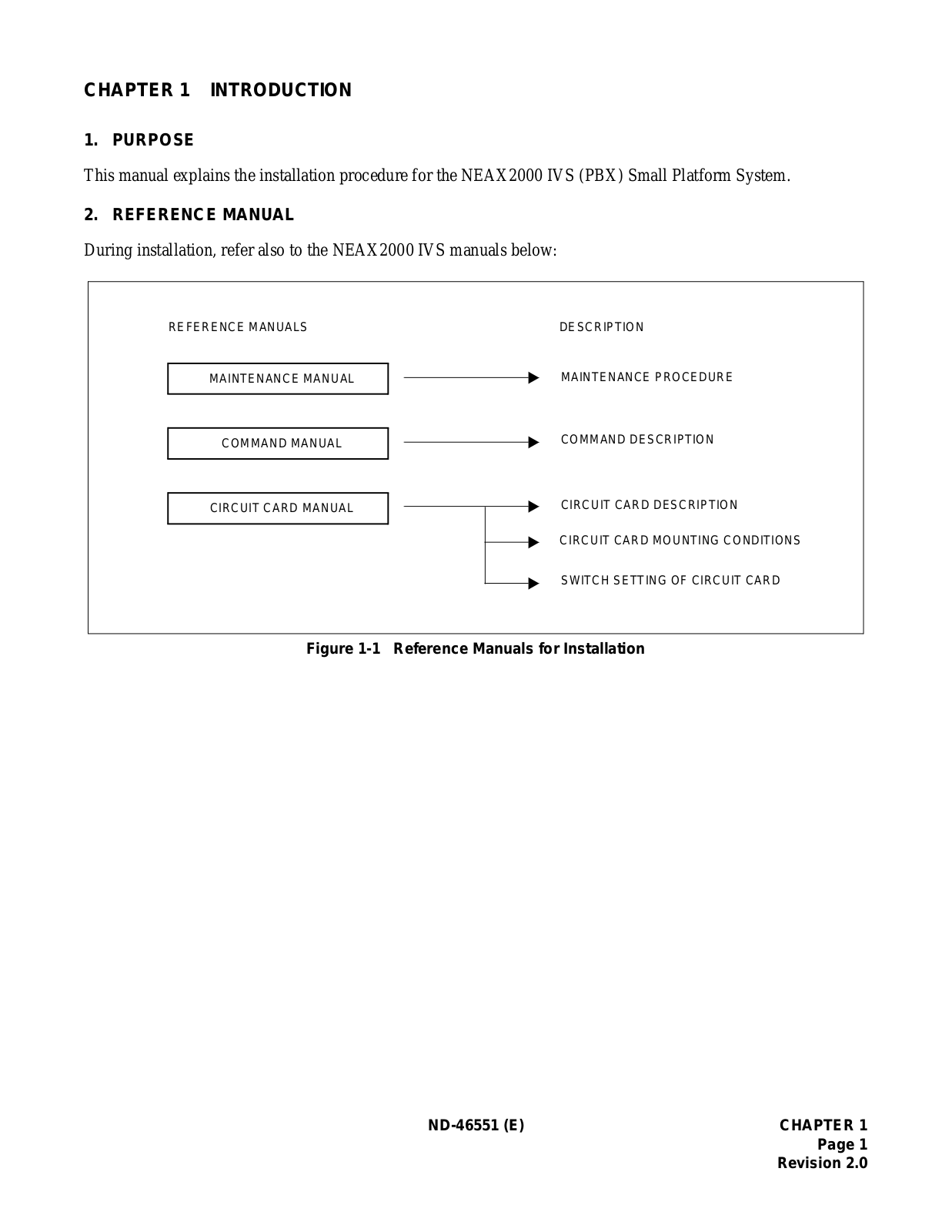
Small Platform System
SMB8000
2
SN1433 CPRAF-A
SN1435 CPRAH-A
SN716
SoftDVD
SOFTDVD PLAYER
SOPHO 2000 IPS
SOPHO 2000 IPS DM
SOPHO IP 5000
SOPHO IP 6000
Soundbar 80
Soundbar 90
SoundStation IP 6000
SoundStation IP 7000
2
SoundTel SV9100
SP-3040
SP-3215
SP4020
2
SP-4046PV
SP4620
SP-46SM
SP5008A
SP-55SM
SP-5710
SP-6520
SP-65SM
SP-70SM
SP-80SM
SP-AS
2
SP B
SpectraView
2
SpectraView 2090
2
SpectraView 242
SpectraView 2490
SpectraView 2690
SpectraView 272
SpectraView FP1375X
SpectraView II MultiSync LCD2690W2-BK-SV
SP-P4046
2
SP-P42C1
2
SP-P42P1
SP-P50C1
SP-P60C1
SP-PS52
SP-RM1
2
SP-RM2
SP-S4046
SP-TF1
2
SP-V65SM
Loading...
Loading...
Nothing found
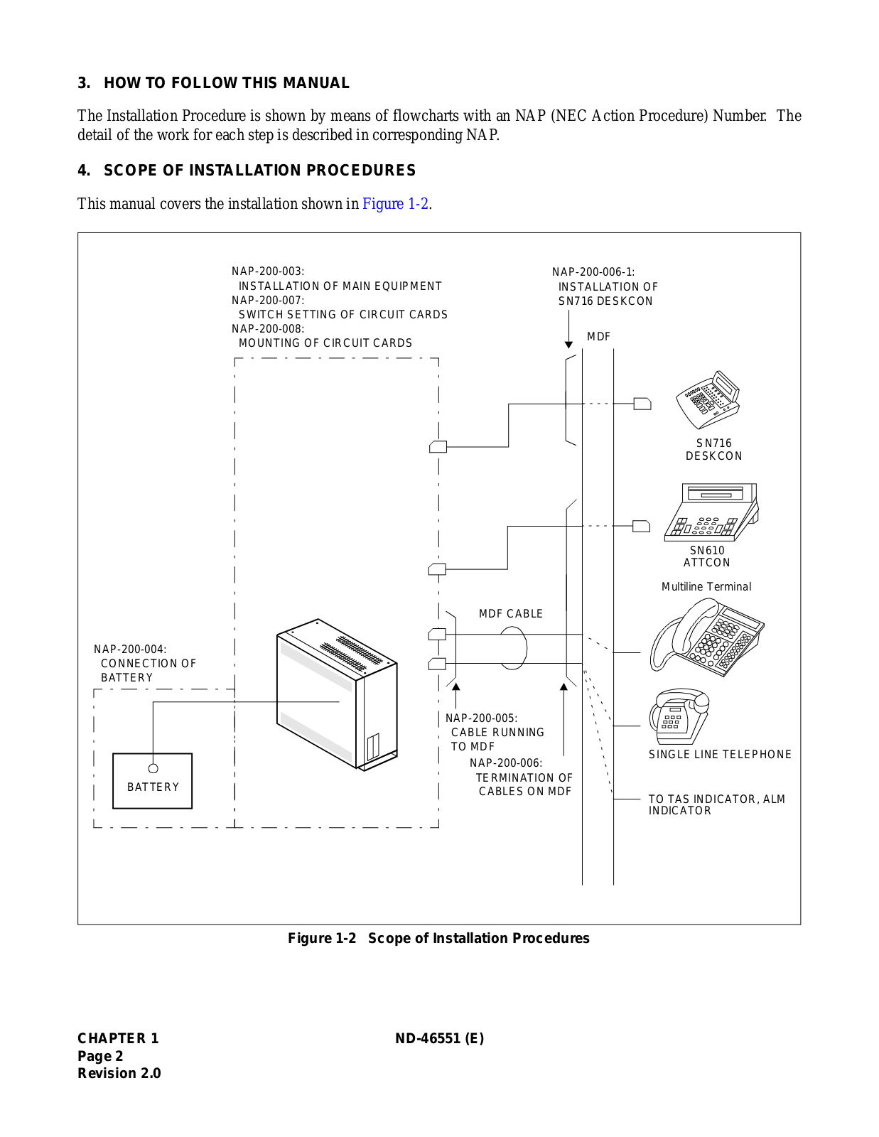
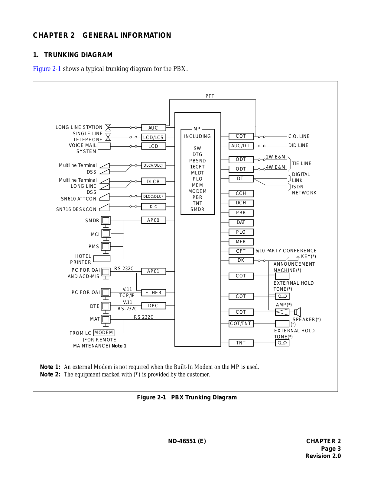
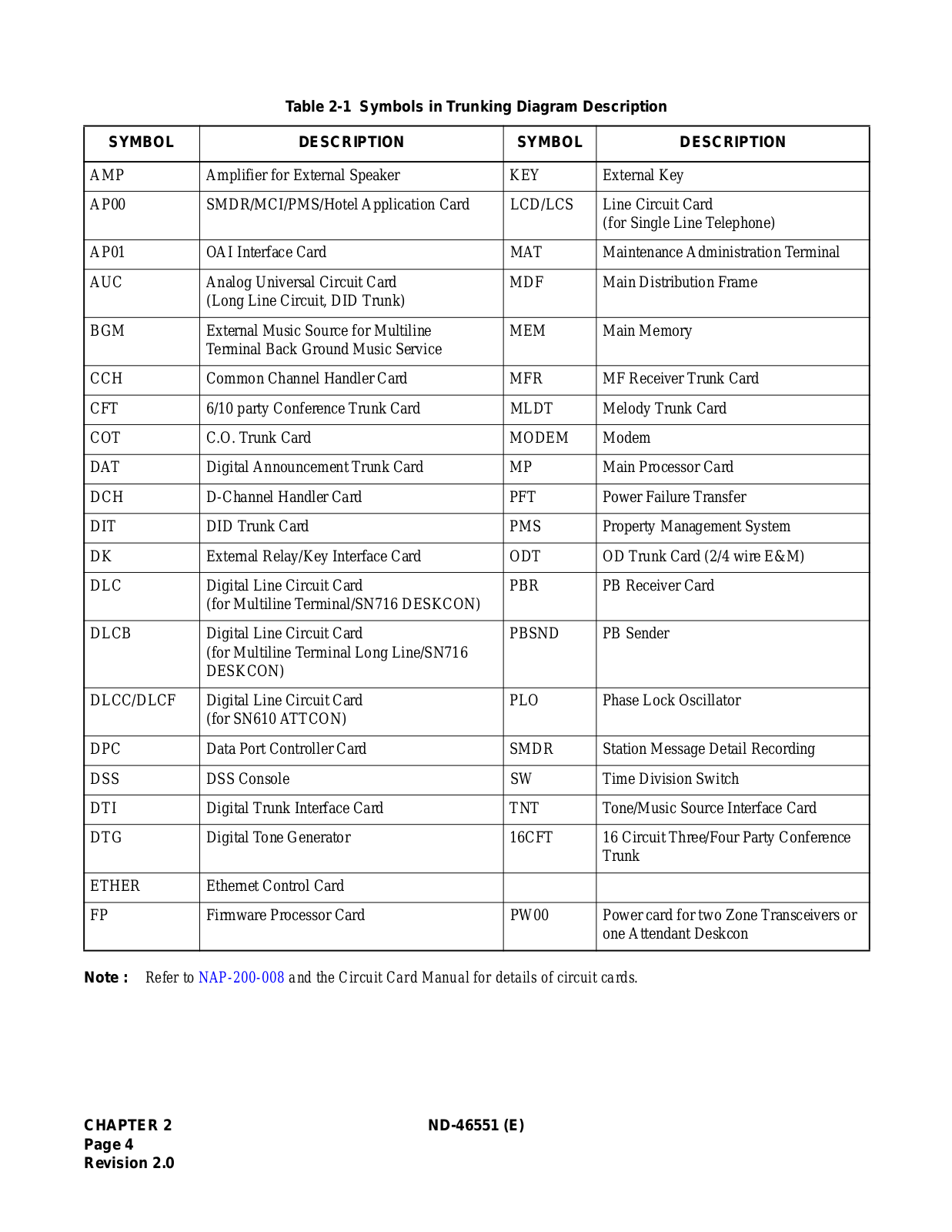
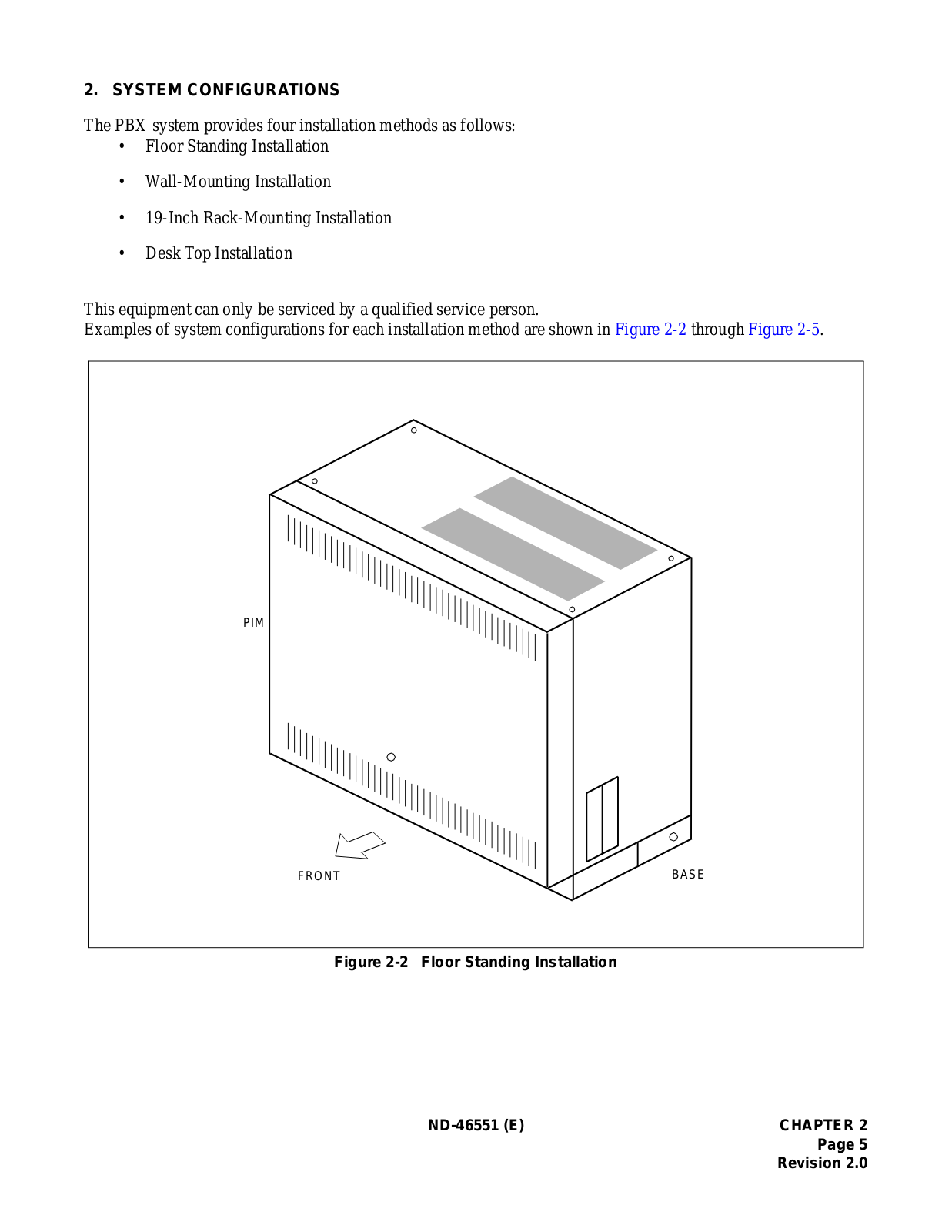
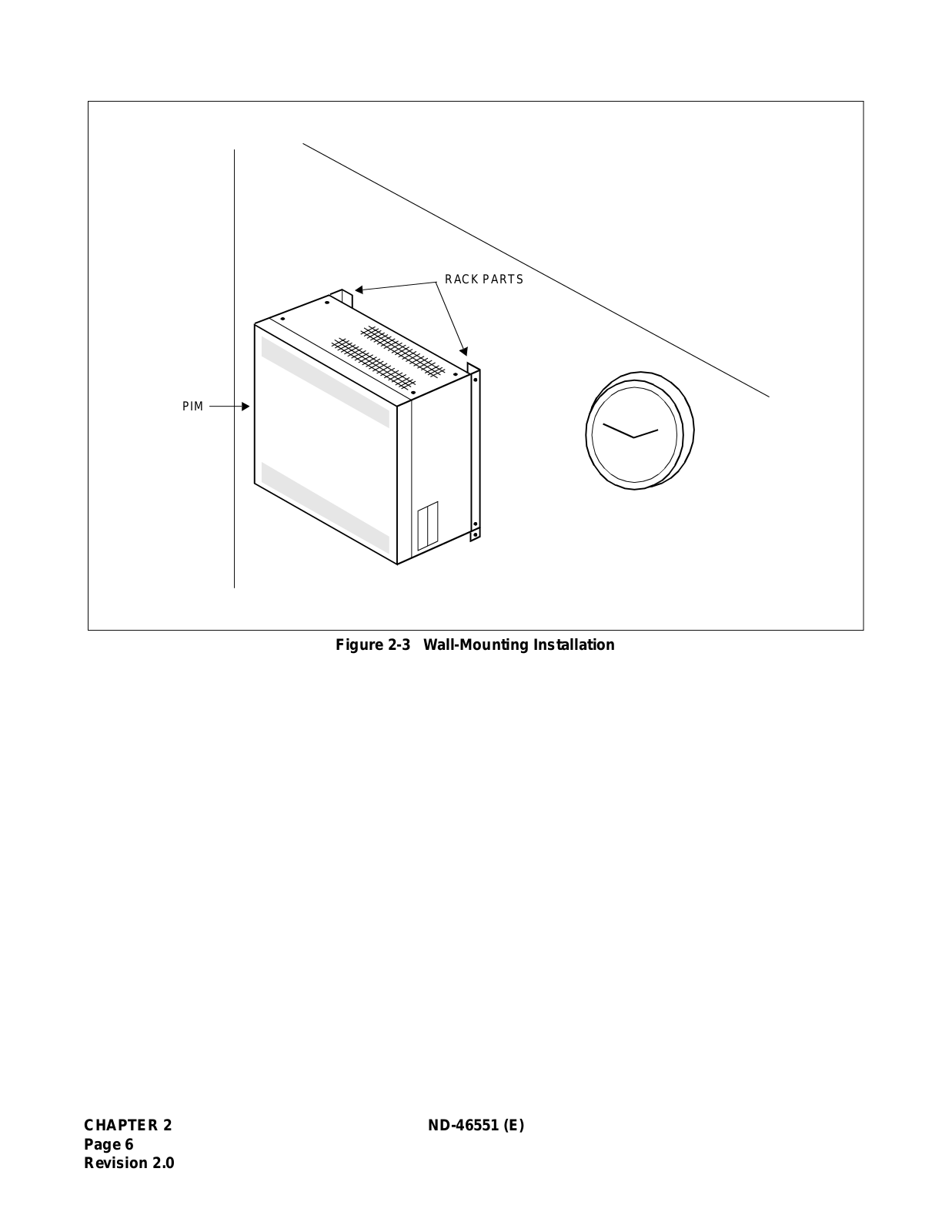
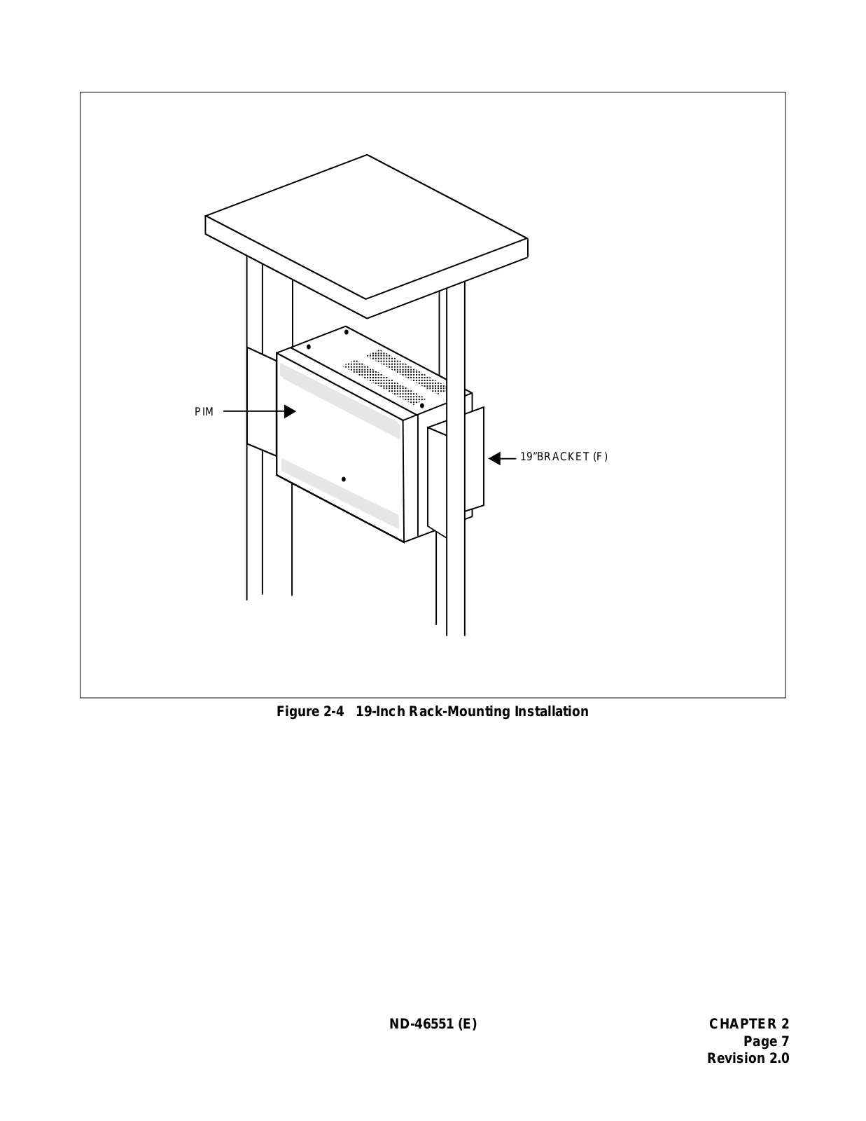
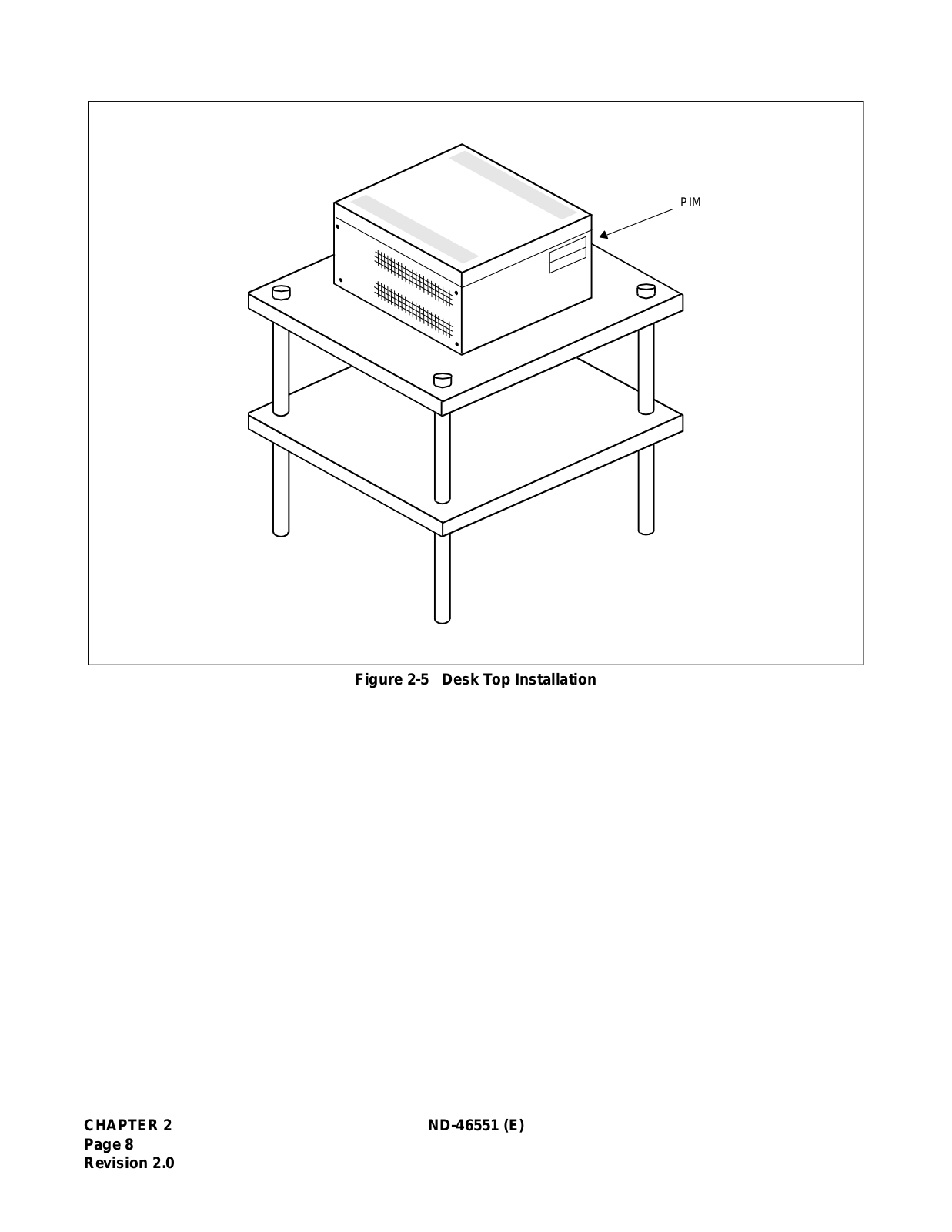
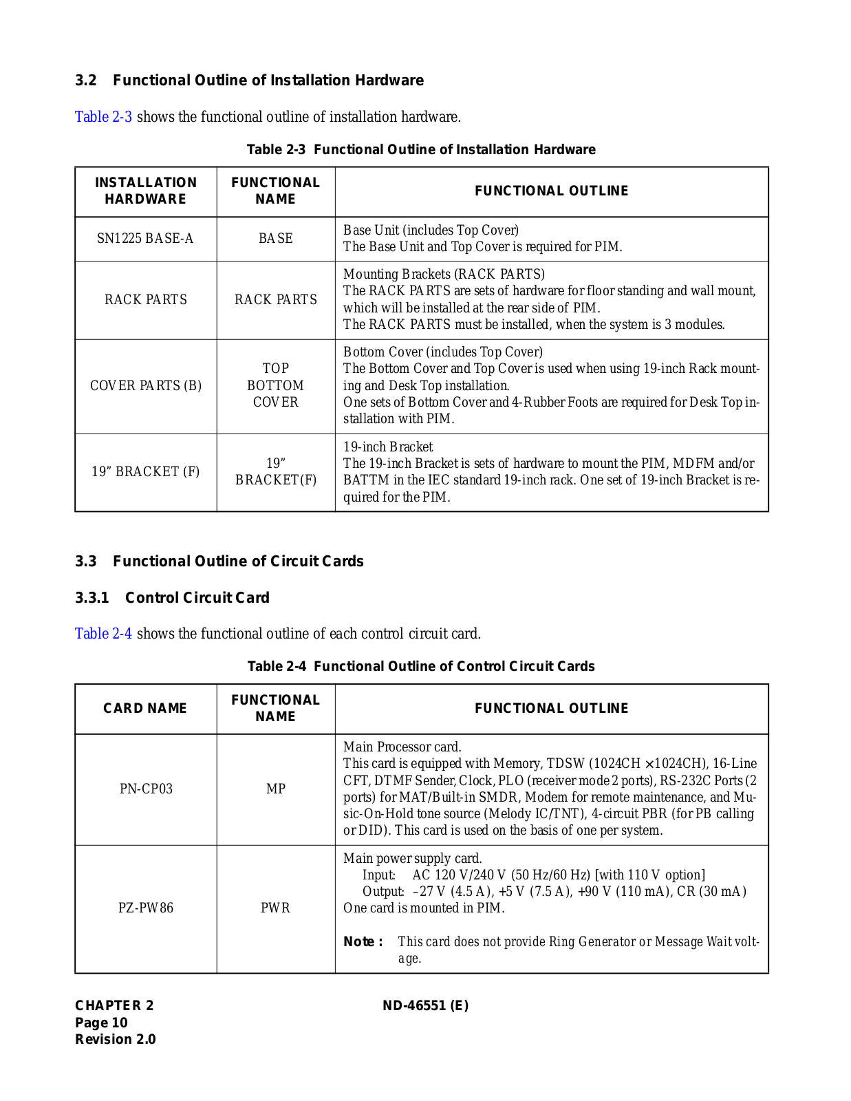
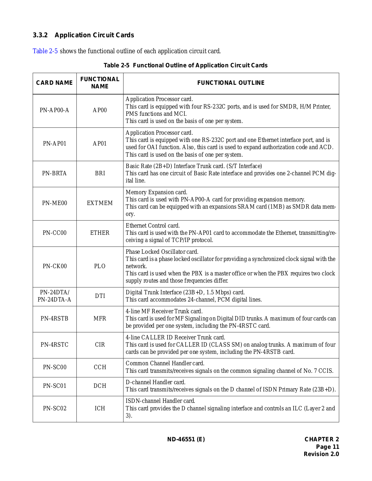
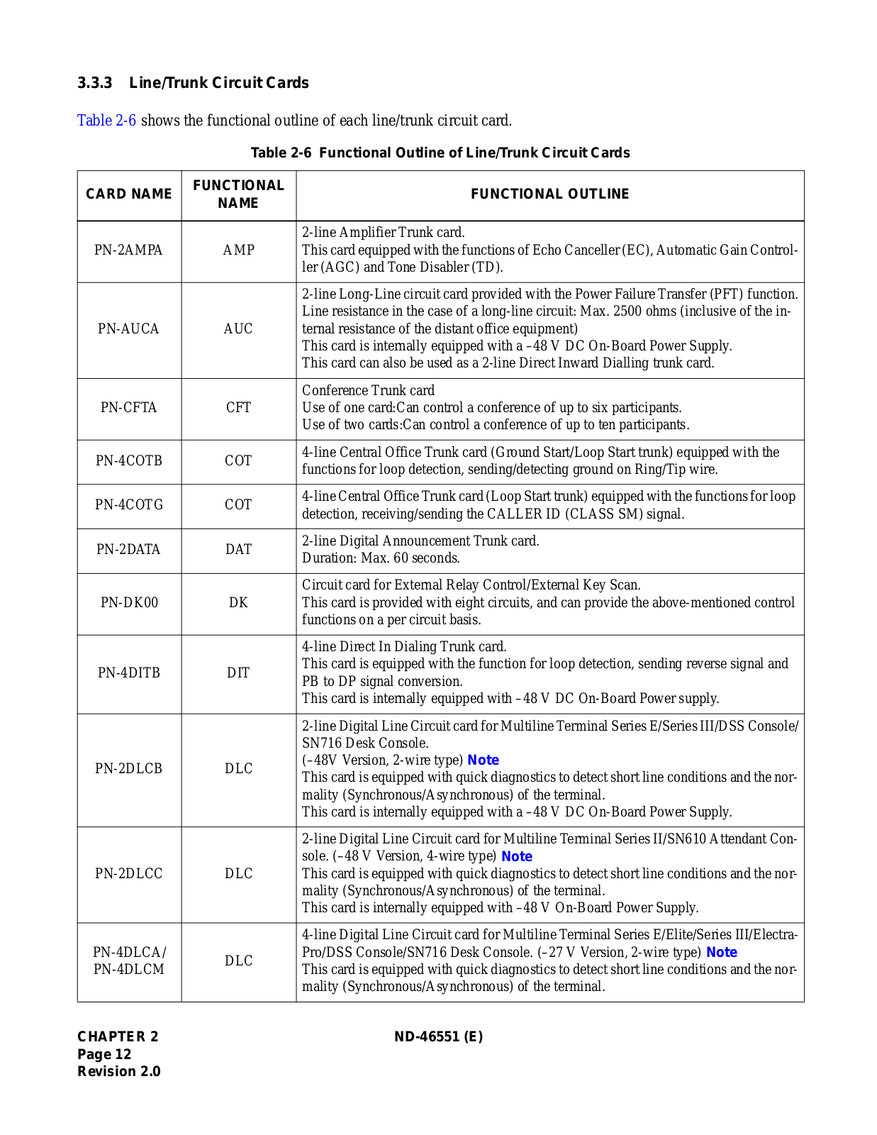
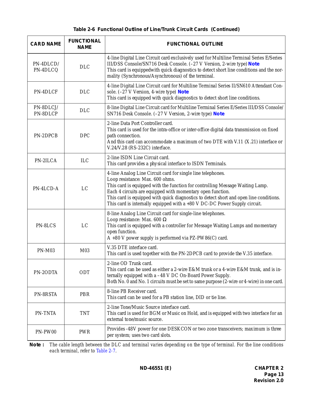
Small Platform System
User Guide
182 pgs
2.34 Mb
0
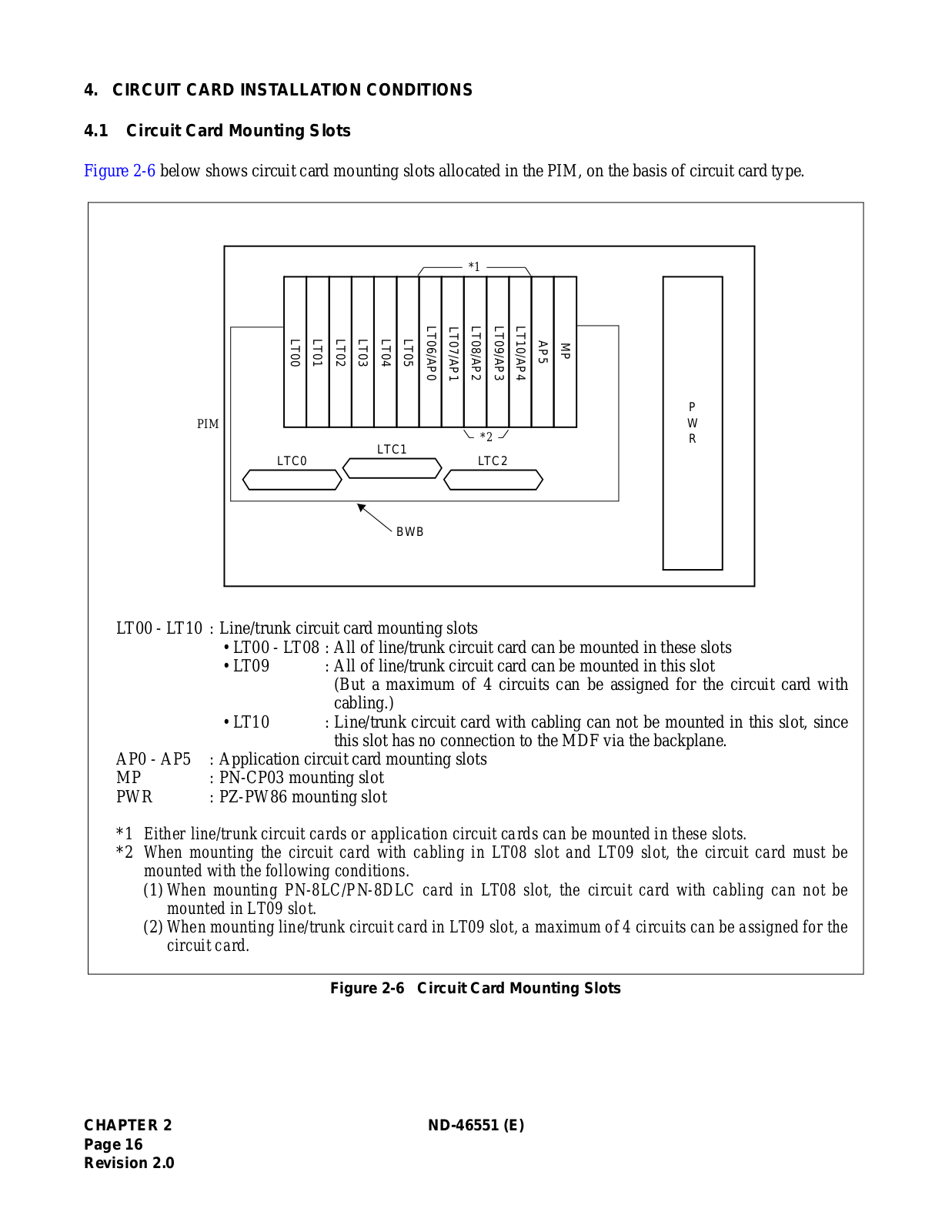
Table of contents
Loading...
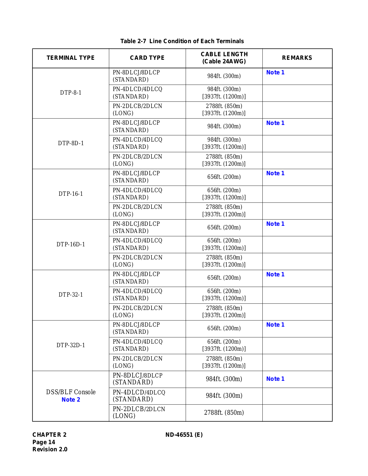
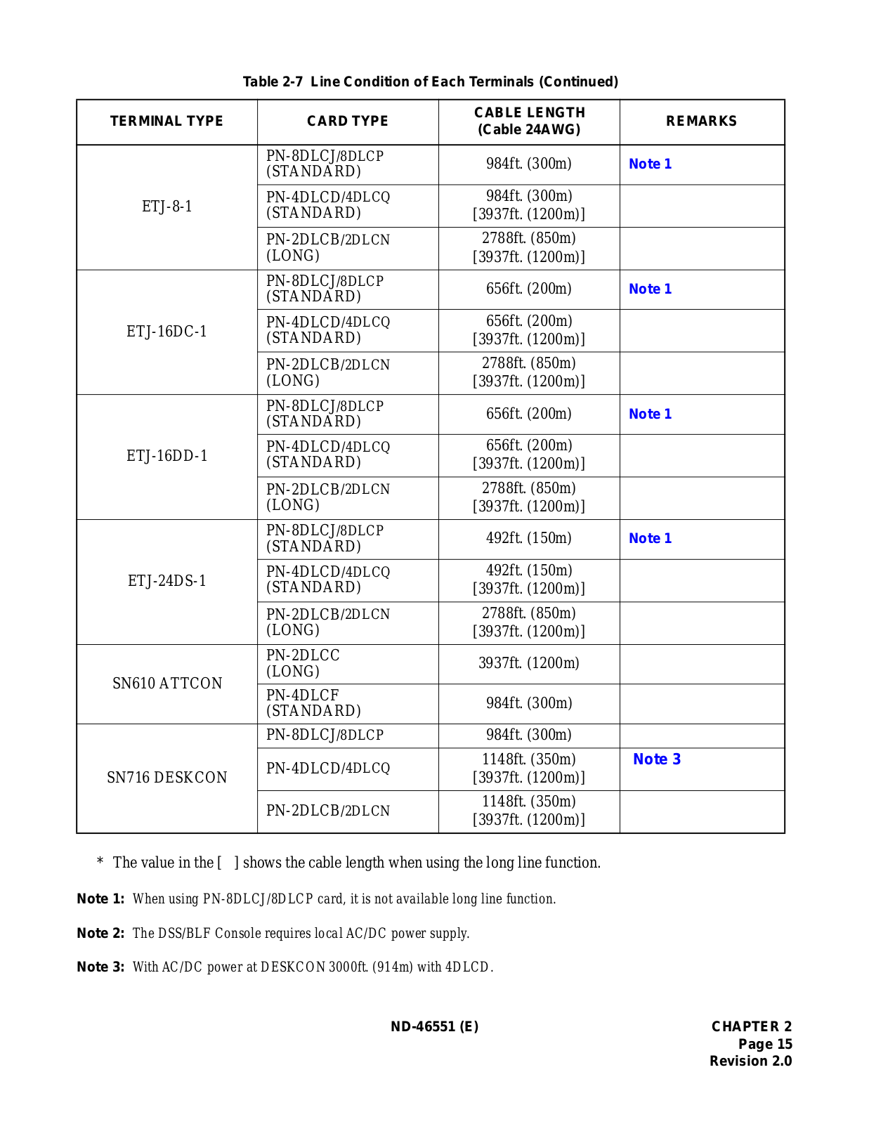
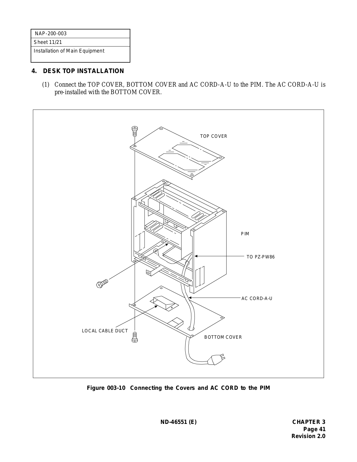
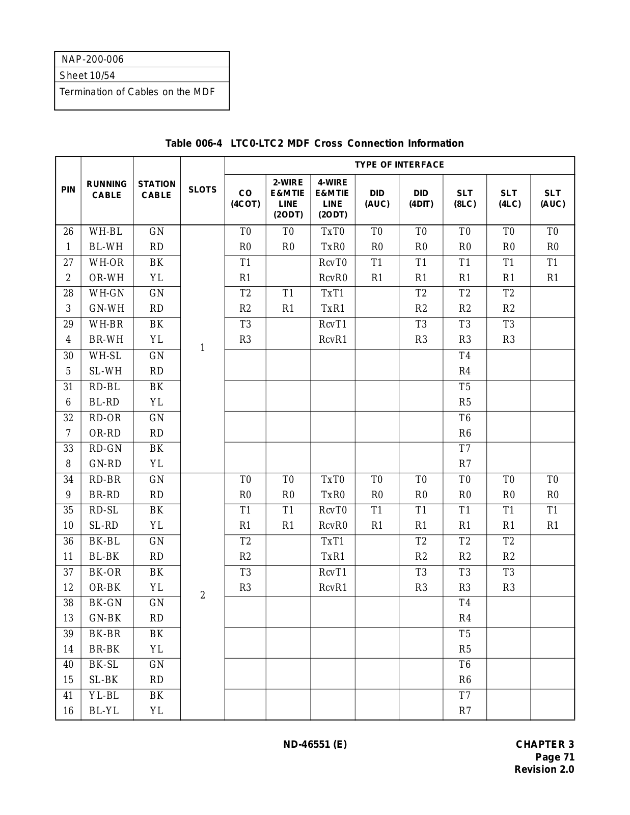
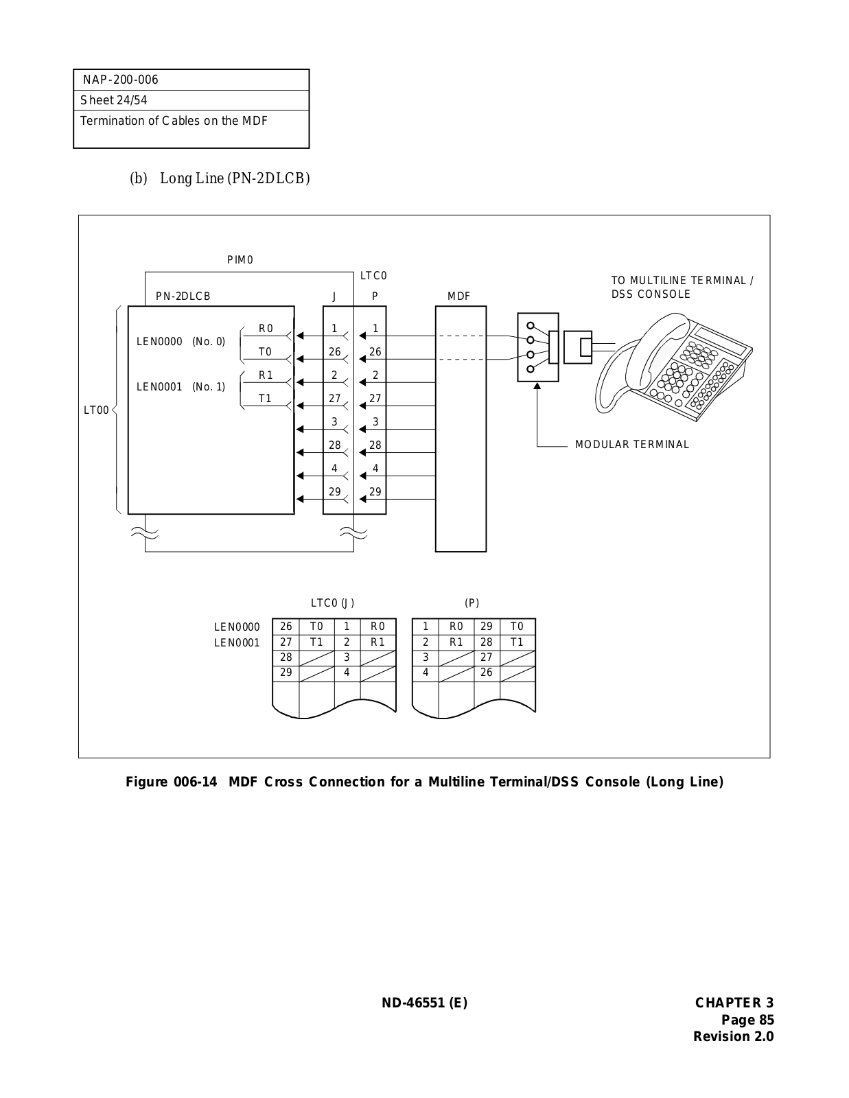
NEC Small Platform System User Guide
...
NEC User Guide
Download
Specifications and Main Features
Frequently Asked Questions
User Manual
Download
Loading...
+
hidden pages
Unhide
You need points to download manuals.
1 point = 1 manual.
You can buy points or you can get point for every manual you upload.
Buy points
Upload your manuals
 Loading...