

Page 1

Setup Guide
S1500 Disk Array Unit
S1500
Page 2

This page is deliberately left empty.
Page 3

Setup Guide
1
www.nec-computers.com
100
Proprietary Notice and Liability Disclaimer
The information disclosed in this document, including all designs and related materials, is the
valuable property of NEC Computers and/or its licensors. NEC Computers and/or its licensors,
as appropriate, reserve all patent, copyright and other proprietary rights to this document,
including all design, manufacturing, reproduction, use, and sales rights thereto, except to the
extent said rights are expressly granted to others.
The NEC Computers product(s) discussed in this document are warranted in accordance with
the terms of the Warranty Statement accompanying each product. However, actual
performance of each product is dependent upon factors such as system configuration, customer
data, and operator control. Since implementation by customers of each product may vary, the
suitability of specific product configurations and applications must be determined by the
customer and is not warranted by NEC Computers.
To allow for design and specification improvements, the information in this document is subject
to change at any time, without notice. Reproduction of this document or portions thereof without prior written approval of NEC Computers is prohibited.
Trademarks
NEC ESMPRO and NEC EXPRESSBUILDER are trademarks of NEC Corporation.
Microsoft, Windows, Windows Server, and MS-DOS are registered trademarks or trademarks of
Microsoft Corporation in the United States and other countries.
Intel and Pentium are registered trademarks of Intel Corporation.
Xeon is a trademark of Intel Corporation.
Novell and NetW are are registered trademarks of Novell, Inc. of the United States.
Datalight is a registered trademark of Datalight, Inc.
ROM-DOS is a registered trademark of Datalight, Inc.
AT is a registered trademark of International Business Machines Corporation in the United States and
other countries.
Adaptec and its logo is a registered trademark of Adaptec, Inc. of United States.
SCSISelect is a trademark of Adaptec, Inc. of the United States.
Adobe, Adobe logo, and Acrobat are trademarks of Adobe Systems Incorporated.
DLT and DLTtape are trademarks of Quantum Corporation of the United States.
All other product, brand, or trade names used in this publication are the trademarks or registered
trademarks of their respective trademark owners.
rev 1.0 April 2006
Copyright 2006
NEC Computers S.A.S.
10 rue Godefroy
Immeuble OPTIMA
92821 PUTEAUX
FRANCE
Page 4

This page is deliberately left empty.
Page 5

FEDERAL COMMUNICATIONS COMMISSION
RADIO FREQUENCY INTERFERENCE STATEMENT
NOTE: This equipment has been tested and found to comply with the limits for a Class A digital
device, pursuant to Part 15 of the FCC Rules. These limits are designed to provide reasonable
protection against harmful interference when the equipment is operated in a commercial environment.
This equipment generates, uses, and can radiate radio frequency energy and, if not installed and used
in accordance with the instruction manual, may cause harmful interference to radio communications.
Operation of this equipment in a residential area is likely to cause harmful interference in which case
the user will be required to correct the interference at the user’s own expense.
Momentary voltage drop prevention:
This network storage unit may be affected by a momentary voltage drop caused by lightning. Use an
AC uninterruptible power supply (UPS) unit to prevent a momentary voltage drops.
i
Page 6
Safety Precautions
Before using this unit, we recommend you read this manual carefully and take all necessary
precautions in order to use this unit safely and correctly, therefore avoiding potential personal or
property damage. Keep this manual nearby for easy reference.
The following symbols are used in this manual so that you can easily understand how to operate the
unit safely and correctly.
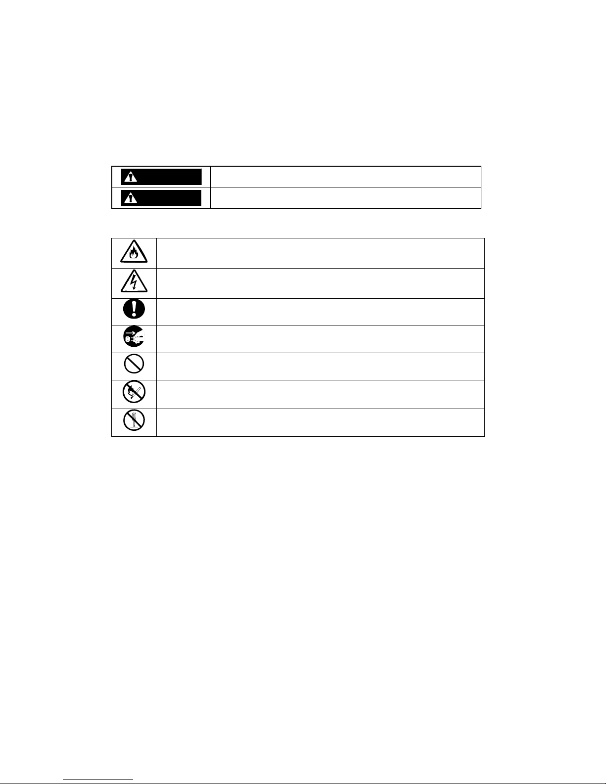
WARNING
Indicates that there is a risk of death or serious injury.
CAUTION
Indicates that there is a risk of burn or injury.
Risks and the necessary actions to reduce risks are indicated individually by the following symbols.
Indicates the risk of smoke emission or fire outbreak.
Indicates the risk of electric shock.
Indicates required general actions for operators.
Indicates the necessity to unplug the power cord from the outlet.
Indicates general prohibitions.
Indicates a device must be kept away from inflammable objects.
Indicates the danger of an injury due to harmful material.
- ii -
Page 7
Notes on Use
The following table includes information necessary for the proper and safe operation of the disk array
unit.
WARNING
Do not use the disk array unit in an area of high humidity. If so, a fault, electrical
shock, or fire may occur.
Do not use the disk array unit in an area where inflammable gas and/or
combustible materials are placed. If so, a fire or explosion may occur.
Do not overload AC outlets with power cords. If so, a fire may occur.
Do not put heavy objects on a power cord. If so, the insulating coating of the
power cord may be damaged, fire may occur, and/or you may be electrically
shocked.
Do not install the disk array unit in a dirty or dusty environment. Remove any dust
adhering to AC outlets and the plugs of power cords. If dust remains adhering to
an AC outlet and/or plug, a fire may occur.
Do not connect the plug of a power cord to an AC outlet with a wet hand. If so, you
may be electrically shocked.
While the disk array unit can accept power in the range of 100 - 240 VAC (50/60
Hz), the power cord shipped with the disk array unit can only accept 220 – 240
VAC. Use 220 – 240 VAC (50/60 Hz) when the included power cord is used. Using
power of a different voltage may cause electric shock, smoke, and/or fire to occur.
The controller of the disk array unit contains a lithium battery. Do not remove the
lithium battery. The lithium battery may explode when it is brought close to fire or
immersed in water. Dispose of the controller according to local ordinance. Contact
your local government for details.
If the disk array unit does not operate normally due to the life of the lithium
batteries, contact your service representative. Do not disassemble the controller,
or replace or charge battery by yourself.
- iii -
Page 8
CAUTION
Do not install the disk array unit and the host systems in an unsafe or unstable
manner. If so, damage may occur to the unit and/or you may be personally injured.
Do not install the disk array unit and the power cords in an area with direct sunshine
or near any apparatus generating heat such as a heater. If so, a fault may occur.
Furthermore, the insulating coating of the power cord may be melted causing fire or
electric shock to occur.
Insert the plug of a power cord to an AC outlet securely. Tightly secure the DC
power cable with the screw. Any power cord shall be routed with sufficient margin to
avoid excess strain from being applied to the plugs of the power cord or the power
cord itself. If a power cord is removed from the AC outlet during operation, data may
be lost and/or a fault may occur.
To prevent electric shocks, connect all power cords to AC outlets with earth
grounding. Connecting the earth line to a gas pipe is extremely dangerous. Never
do it.
Before connecting or removing a peripheral device from the disk array unit, turn off
all the power switches of the disk array unit and peripherals and pull out the power
cords from the AC outlets or distribution board. If you do not do so, some units may
be damaged and/or you may be electrically shocked.
To carry or reinstall the disk array unit, disconnect all cables and power cords
beforehand. If you do not do so, some units may be damaged, you may be
electrically shocked, and/or a fire may occur.
To install the unit in a rack, observe the following guidelines.
1. Temperature – Give consideration to installing the equipment in an environment
compatible with the manufacturer's recommended ambient temperature (TMRA).
2. Reduced Air Flow – Do not compromise the amount of air flow required for safe
operation of the equipment is not compromised.
3. Mechanical Loading – Do not achieve hazardous conditions due to uneven
mechanical loading.
4. Circuit Overloading – Give consideration to the connection of the equipment to the
supply circuit and the effect that overloading the circuits might have on over current
protection and supply wiring. Appropriate consideration of equipment nameplate
ratings should be used when addressing this concern.
5. Reliable Grounding – Maintain reliable grounding of rack-mounted equipm ent. Pay
particular attention to supply connections other than direct connections to the
branch circuit (e.g., use of power strips).
- iv -
Page 9
CAUTION
Handling optical fibers
Handle optical fibers carefully and gently.
The minimum bending radius of optical fibers must be 30 mm.
Do not apply any shock (e.g., let it fall on the floor).
Attach a protective cap to all empty connectors (on the server side, too).
Keep the connector cap for future use when a cable is connected.
Dust and/or dirt may attenuate the optical power of optical fiber and cause data
errors to occur. Clean any optical fiber cable whenever it is inserted into the mating
connector as described belowe. Never clean a connector in which light is present in
the fiber.
1. Use a lint-free "wipe" that has been dipped into alcohol (use of 99%
reagent-grade alcohol is recommended).
2. Wipe immediately after with a dry lint-free wipe.
Blow-dry using a can of clean, compressed air
Handling of the DAC-DE cable
Improper handling of this cable may cause a decrease of electric characteristics and/or
mechanical destruction (disconnection). Note the following:
1. Route the cable with sufficient margin.
2. Do not apply stress to the cable (e.g., strongly pulling it).
3. Ensure a minimum bending radius of 50 mm.
Anti-static measures
Be sure to take anti-static measures (e.g., wear a wrist strap) when working with
electronic components such as Host Bus Adapters (HBA) and disk drives.
Alternatively, put one of your hands on the metallic (unpainted) part of the storage unit
before handling such a component.
Disposing of the productl
Disposing of your used NEC product
In the European Union
EU-wide legislation as implemented in each Member State requires that used electrical and
electronic products carrying the mark (Left) must be disposed of separately from normal
household waste. The equipment with this mark may include electrical accessories
(e.g. memory cards). When disposing of used NEC products, you should comply with
applicable legislation or such terms which may have been agreed between NEC and
your company regarding used products. This mark on electrical and elect ronic
products only applies to the current European Union Member States.
Outside the European Union
If you wish to dispose of used electrical and electronic products outside the European
Union, please contact your local authority and ask for the correct method of disposal.
- v -
Page 10
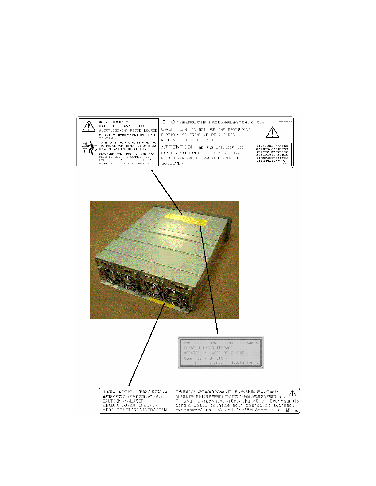
Safety Indications
Warning labels are attached to components (or a location in their vicinity) that pose a possible danger
or to inform the user that a hazardous situation may arise when operating the disk array unit. (Do not
intentionally remove or damage any of the labels.)
If you find any labels totally/partially removed or illegible due to damage, contact your sales
representative.
- vi -
Page 11

Power Supply
- vii -
Page 12

- viii -
Page 13
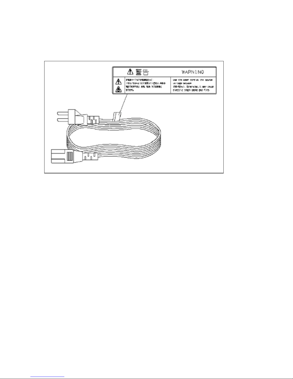
AC Power Cord
220-240 v
220-240 v
- ix -
Page 14

Preface
Congratulations on your purchase of this NEC Disk Array Unit.
This Setup Guide is intended for users who can provide server system configuration and network
setup.
The Setup Guide presumes that the maintenance system meets the following requirements:
Server to be connected:
NEC Express5800 series
OS :
Windows 2000 or Windows Server 2003
Configuration:
Direct connection with server only
Miscellaneous:
Modems are excluded from the target units.
The Setup Guide describes the general procedures of the following operations:
Setup of the NEC Storage unit itself.
Installation of the WebSAM NEC Storage Manager server and client software.
Configuration and start of SystemGlobe AccessControl and SystemGlobe
StoragePathManager utilities.
The Setup Guide only describes the setup procedures for a new installation. To add units to the system
or perform system configuration changes, refer to the relevant guides.
For detailed configuration procedures, refer to the "Disk Array Unit User’s Guide" and to the user's
guide associated with each software product.
We recommend you ask your NEC trained service representative for assistance with the procedures
outlined in this Setup Guide.
- x -
Page 15

Text Conventions
The following conventions are used throughout this guide. For safety symbols, see "SAFETY
INDICATIONS" provided earlier.
IMPORTANT:
Items that are mandatory or require attention when using the disk
array unit
NOTE:
Helpful and convenient pieces of information
This Setup Guide uses the following terms to indicate specific devices.
Disk array unit Indicates the S1500.
Disk enclosure Indicates either an additional Fibre Channel (FC) Disk
Enclosure (sold separately) or an additional SATA Disk
Enclosure (sold separately).
Disk drive Indicates the hard disk drive and its dedicated tray (sold
separately).
HDD tray Indicates the hard disk drive tray only, with no hard disk drive
installed.
Host System Indicates an NEC Express5800 series server.
Host bus adapter (HBA) Indicates the Fibre Channel controller for the NEC
Express5800 series
DAC Indicates the disk array controller .
CONT Indicates the disk array controller.
BBU Indicates a battery backup unit.
DE Indicates a disk enclosure.
- xi -
Page 16

Contents
1. General Description.....................................................................................................1
1.1 First Setup Flow ...................................................................................................................1
1.2 Preparation............................................................................................................................ 2
1.3 Unpacking ............................................................................................................................ 2
1.4 Inspection .............................................................................................................................3
2. Host System.................................................................................................................4
2.1 Installing the Host Bus Adapter (HBA)................................................................................4
2.2 Installing the HBA Driver....................................................................................................4
2.3 World Wide Port Name (WWPN) of HBA...........................................................................4
2.4 Installing SystemGlobe StoragePathManager (SPM) .......................................................... 5
2.4.1 Before Setup ................................................................................................................. 5
2.4.2 Installation ....................................................................................................................5
3. NEC Storage S1500 ..................................................................................................... 6
3.1 Installing an Optional Battery .............................................................................................. 6
3.2 Installing the Disk Array Unit and a FC Disk Enclosure in a Rack .....................................9
3.2.1 Installing the Unit using a Rack Mount Kit.................................................................. 9
3.3 Connecting the Power Cords.............................................................................................. 13
3.3.1 Connecting AC Power Cords...................................................................................... 13
3.4 Setting the ENC ID Switch and Connecting the HSSDC-HSSDC Cable ..........................18
3.4.1 Adding a FC Disk Enclosure (Port DP0)....................................................................18
3.4.2 Adding a FC or SATA Disk Enclosure (Port DP1)..................................................... 19
3.5 Installing a FC/SATA Disk Drive....................................................................................... 20
3.6 Security Key and Front Panel.............................................................................................22
3.6.1 Locking/Unlocking with the Security Key.................................................................22
3.6.2 Installing the Front Panel............................................................................................22
3.6.3 Removing the Front Panel ..........................................................................................23
4. Connecting a PC for the Setup Wizard.................................................................... 24
4.1 Connecting a PC for the Setup Wizard............................................................................... 24
4.2 Powering-on .......................................................................................................................26
4.3 Powering On/Off the Disk Array Unit................................................................................ 28
5. Initialization by the Setup Wizard.............................................................................33
5.1 Start Procedure ...................................................................................................................33
5.2 Initialization........................................................................................................................ 34
5.3 System Configuration Change............................................................................................ 34
6. Installing WebSAM NEC Storage Manager Server and Client ...............................49
6.1 Connecting the WebSAM NEC Storage Manager Server (through LAN cable)................49
6.2 Installing the WebSAM NEC Storage Manager Server and Setting up the Environment.. 50
6.2.1 Environment Settings of WebSAM NEC Storage Manager Server............................ 52
6.3 Installing the WebSAM NEC Storage Manager client and Setting up the Environment ...56
6.3.1 Installing the WebSAM NEC Storage Manager Client...............................................56
6.3.2 Starting the Client....................................................................................................... 58
6.4 NEC Storage Settings......................................................................................................... 62
6.4.1 License Key Registration (for other than the Base Product) <If Used Only>............62
6.4.2 Pool Binding............................................................................................................... 65
6.4.3 Logical Disk Binding.................................................................................................. 73
6.4.4 Spare Binding ............................................................................................................. 80
- xii -
Page 17

6.5 Setting and Starting Access Control................................................................................... 84
7. Connecting the Disk Array Unit to a Host System.................................................. 85
8. SPM Setting and Status Check.................................................................................87
9. Connection Check.....................................................................................................88
10. Troubleshooting..................................................................................................90
- xiii -
Page 18
1. General Description
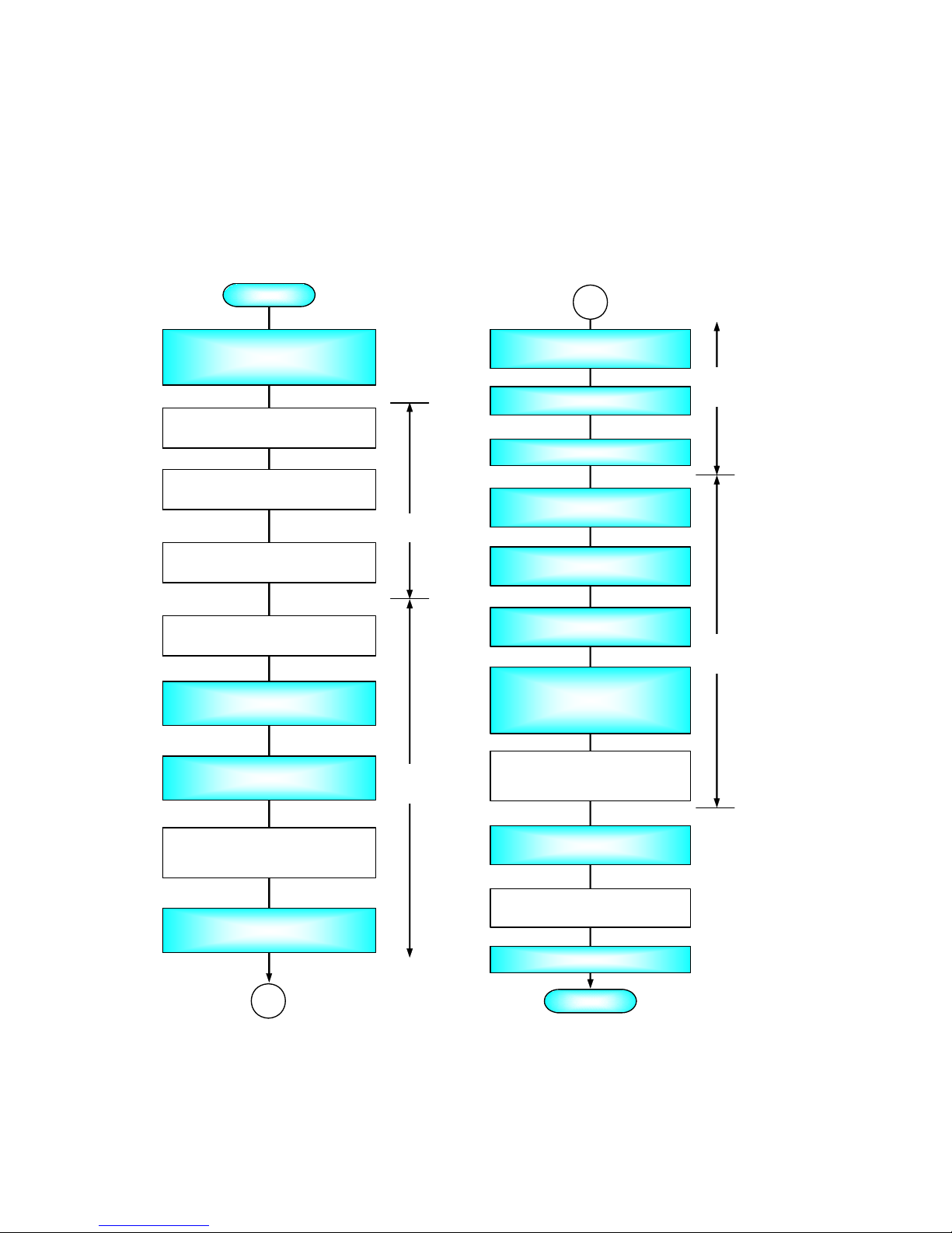
1.1 First Setup Flow
Set up the disk array unit according to the flowchart shown below.
¾ White boxes relate to optional hardware or software.
¾ Blue boxes describe mandatory steps.
Preparing, Unpacking, Checking
components in package, checking
appearance and structure
START
END
Connecting the PC for the Setup
Wizard
Installing the HBA in the Host System
(if not installed)
Installing the HBA driver in the Host
System (if not installed)
Installing the SP S
(if you have purchased)
Installing an optional battery
(if you have purchased)
Installing the DAC/DE in rack assembly
Connecting power cords
Setting the ENC-ID switch, connecting
the DAC/DE cable
(if a DE is additionally installed)
Installing a FC disk drive
1
Powering-on
Initial Setup by the Setup Wizard
Connecting the NEC Storage server
(via LAN)
Installing the NEC Storage server
and environmental setup
Installing the NEC Storage client and
environmental setup
Configuring with NEC Storage
(license key registration, pool and
logical disk configuration)
Setting and Starting Access Control
(if you have purchased Access
Control)
Connecting to the Host System
(via FC cable)
SPS Configuring and Verification
Checking connection
1
Host System
NEC Storage
S1500
NEC Storage
Manager
NEC Storage
S1500
- 1 -
Page 19

1.2 Preparation
The following items are required for setup. Prepare them before starting the setup work.
A PC for the Setup Wizard (Maintenance system)
Operating system: Windows 2000, Windows Server 2003, or Windows XP
100/10Base interface, Internet Explorer Version 5.0 or later
A Shielded LAN cable (to be used with the PC for the Setup Wizard)
Cross-Over cable to connect the unit directly with the PC for the Setup Wizard, or
Straight cable to connect the unit with the PC for the Setup Wizard via a hub
Phillips screwdriver No. 1
IP addresses listed below
IP address Remarks
Disk array unit
- LAN port on controller 0 10. 1. 1. 1
- LAN port on controller 1 10. 1. 1. 2
- MNT port on controller 0 10. 1. 0. 10 Fixed
- MNT port on controller 1 10. 1. 0. 1 1 Fixed
LAN port on PC for Setup Wizard 10. 1. 0. 1 Default
LAN port for NEC Storage se rver (for every port)
LAN port on power control server (for every port)
Three or more persons are required to carry the unit.
At least three FC disk drives are required for setup. You need to purchase the necessary FC
disk drives separately. See the User's Guide (stored on CD-ROM) that shipped with the unit for
details.
1.3 Unpacking
Unpack the shipping carton, and remove the packing materials. Leave the shipping carton open at least
9 hours before unpacking so that the unit acclimates to the ambient temperature enough to prevent dew
condensation.
Open the package and take out the disk array unit and accessories from the package carefully.
The disk array unit is very heavy, you must enlist help to lift it in order to prevent personal injury. To
remove the disk array unit from the package, more than three people should always support the bottom
of the unit, without holding it by the power supply or the projections of the controller.
The package is specially designed for the transportation of a precision device. Do not dispose of the
package. If repair ever becomes necessary, the package is required to return the disk array unit to the
factory.
- 2 -
Page 20

1.4 Inspection
After unpacking, check that all the components listed in the table below are provided. If any of the
components are missing, contact your sales representative.
Next, inspect the disk array unit and accessories. If any of the components are damaged, contact your
service representative.
Components for S1500 disk array unit
No. Product name Designation Qty
1 Rack Mount Kit 243-532114-003 1
2 Front Mask 243-408203-002 1
3 AC Cord ASSY (100VAC, 3m) 134-544764-031 2
4 S1500/S500 Micro Program CD 243-190025-110 1
5 User's Guide 856-850725-101 1
6 Packing List 856-083415-501 1
- 3 -
Page 21

2. Host System
2.1 Installing the Host Bus Adapter (HBA)
If the target HBA has already been installed in the host system, you may skip this procedure.
Otherwise, install the HBA in host system according to the manuals of the HBA and the host system.
2.2 Installing the HBA Driver
If the target HBA driver (provided with the HBA) has already been installed, you may skip this
procedure.
Otherwise, install the HBA driver according to the Setup Guide of the driver.
2.3 World Wide Port Name (WWPN) of HBA
Take note of the WWPN of the HBA to use the WWN mode in Access Control.
- 4 -
Page 22

2.4 Installing SystemGlobe StoragePathManager (SPM)
You may skip this procedure if you have not purchased the SPM.
2.4.1 Before Setup
Note the following before starting the setup of the SystemGlobe StoragePathManager (SPM).
1. If you setup the SPM in a Windows 2000 Service Pack 2 or Service Pack 3 environment, be
sure to apply the HotFix (Q323289_W2K_SP4_X86_JA.exe) stored on the Setup CD-ROM.
The HotFix solves memory leaks problem that affect the SPM. In a Service Pack 4
environment, you do need not to apply the HotFix.
2. Do not connect the NEC Storage with the host system using several paths before the setup of
SystemGlobe StoragePathManager has completed. (Do not connect the NEC Storage with the
host system unless you have completed all the necessary setup procedures described in
Chapter 6.) If the NEC Storage is connected with the host system using several paths,
powering on the server may cause fatal damages to the file system.
3. If the NEC ESMPRO Agent is installed in the system, stop the [Alert Manager Main Service]
feature before starting the setup of the SystemGlobe StoragePathManager to ensure
registration of the link function.
4. To use the CLUSTERPRO or MSCS, first set up the SystemGlobe StoragePathManager, then
CLUSTERPRO or MSCS.
5. To update the SystemGlobe StoragePathManager in an environment where the
CLUSTERPRO or MSCS is being used, conduct the update process sequentially node by
node. If the group is working in target node, move the group to another node before starting
the update, and move it back after completion of the update. For more information on how to
move a group, refer to the manual provided with the product.
2.4.2 Installation
Take the following steps to install the SystemGlobe StoragePathManager using the Setup CD-ROM.
1. Power off the server. Entirely disconnect the NEC Storage unit(s) from the server.
2. Power on the server. Login the system as a user who has administrative authority, and insert
the Setup CD-ROM into the CD-ROM drive.
3. Follow the instructions of the StoragePathManager Installer.
For more information, refer to the Installation Guide provided with the product.
- 5 -
Page 23
3. NEC Storage S1500
3.1 Installing an Optional Battery
You may skip this procedure if you have no optional battery, or if the optional battery has already been
installed in the unit.
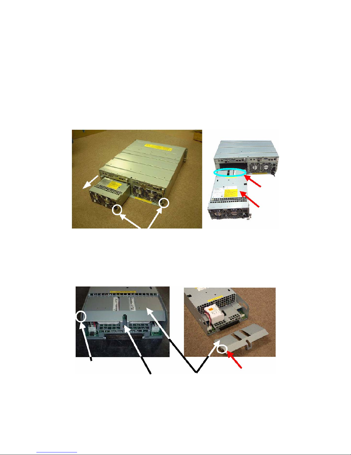
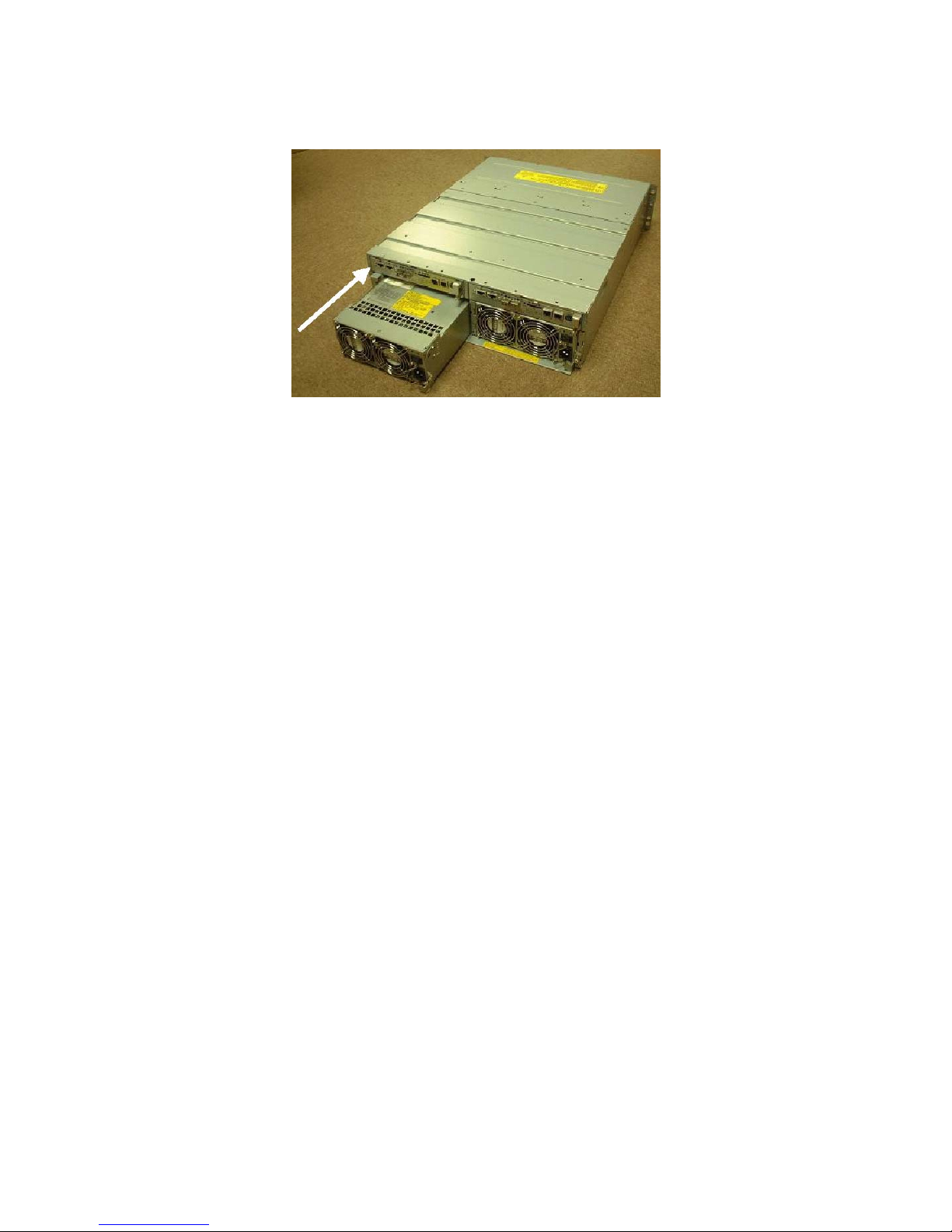
1. Loosen the screw of the ejector that secures the power supply to which you wish to add an
optional battery.
2. Put your finger onto the ejector's protrusion, and pull it forward.
3. When the ejector reaches a 90 degrees angle, pull out the power supply.
BBU GUIDE
Power supply
Ejector fixing screw
Figure 3.1.1 General View of the Unit
4. Turn the screw that secures the BBU GUIDE to the power supply you removed (Figure 3.1.1),
and remove the BBU GUIDE. You can easily remove the BBU GUIDE by pushing the catch
at the left end of guide towards the inside.
Figure 3.1.2 shows the power supply viewed from the other side.
Catch
Catch
BBU GUIDE
BBU GUIDE fixing screw
Figure 3.1.2 Power Supply
5. With the battery backup unit label facing up, install the optional battery at the position shown
in the figure below, and insert the optional battery connector into the power supply connector
Power supply connector
- 6 -
Page 24
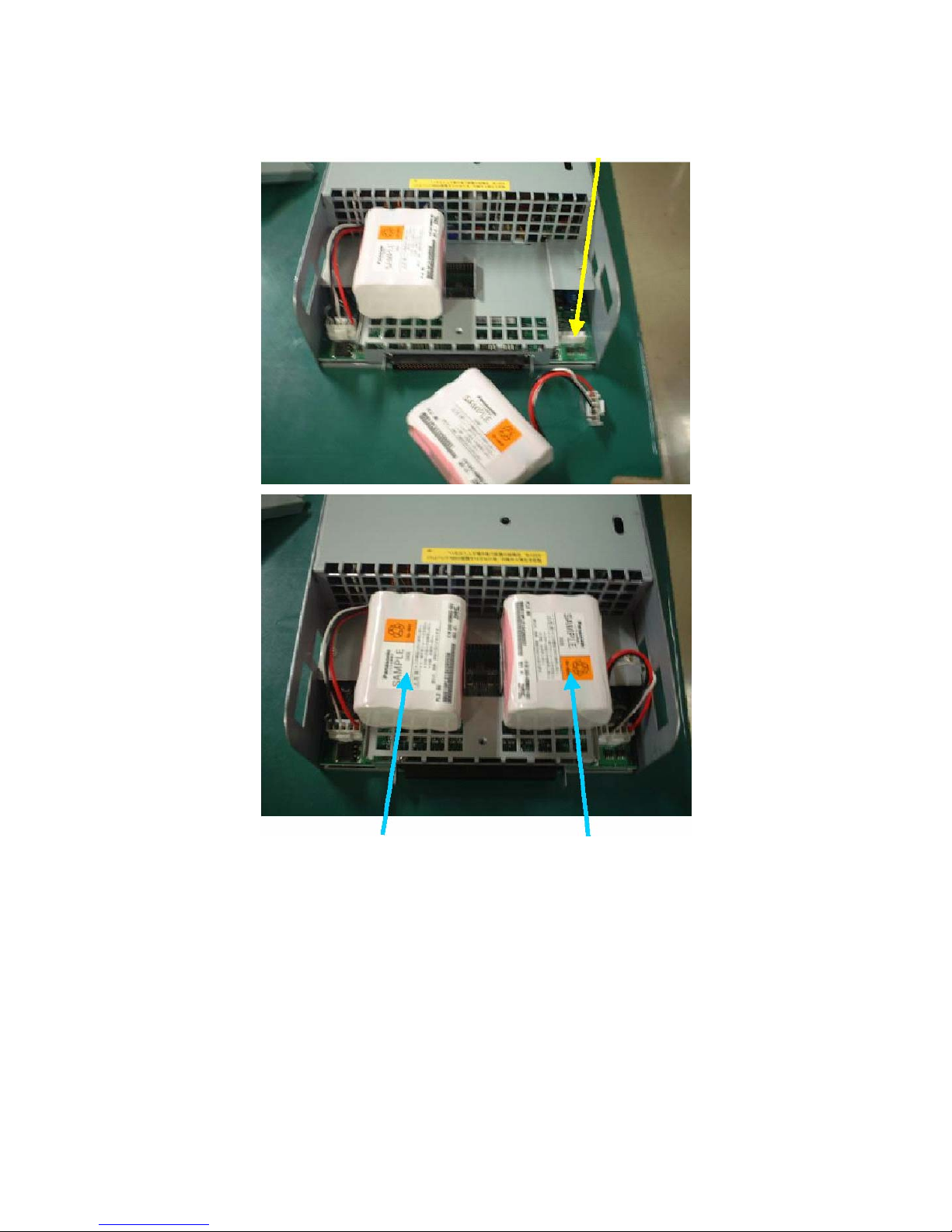
until it is locked.
Standard battery Optional battery
Figure 3.1.3 BBU (Battery Backup Unit)
6. Install the BBU GUIDE (removed in step 5) on the power supply.
Insert the three points on the end of the BBU GUIDE into the net of the power supply, and
place it on the Battery Backup Unit.
7. Install the screw to secure the BBU GUIDE.
- 7 -
Page 25
8. While the ejector is open (at the up position), insert the power supply containing the optional
battery into the slot as far as it will go.
Figure 3.1.4 Inserting Power Supply
9. Push the ejector's protrusion to turn the ejector (to the down position), and insert the power
supply.
10. Tighten the screw that secures the ejector.
11. Repeat steps 2 to 11 for adding an optional battery to the other power supply.
- 8 -
Page 26

3.2 Installing the Disk Array Unit and a FC Disk Enclosure in a
Rack
Install the NEC Storage S1500 disk array unit, FC disk enclosure), and / or SATA disk enclosure in the
rack. Place the disk array unit at the bottom of the rack, and place the disk enclosures above the disk
array unit.
IMPORTANT: The NEC Storage S1500 disk array unit weighs
40 kg or more.
The disk enclosure weighs 34 kg or more.
To install these devices in the rack, keep in mind that at least
three persons should lift the units.
3.2.1 Installing the Unit using a Rack Mount Kit
NOTE: The following procedures detail the installation of a rail
on the left part of a rack (viewed from the front). Install a rail
on the right part of a rack using a similar procedure.
The left and right rails are different from each other. Use the
correct rail when installing it on the rack. (See the figure
below.)
For each rail, the face labeled ‘inner’ must face the rear (see the
figure below).
Rail (R)
Rail (L)
Front
Rear
Inner
Figure 3.2.1 Rail
- 9 -
Page 27
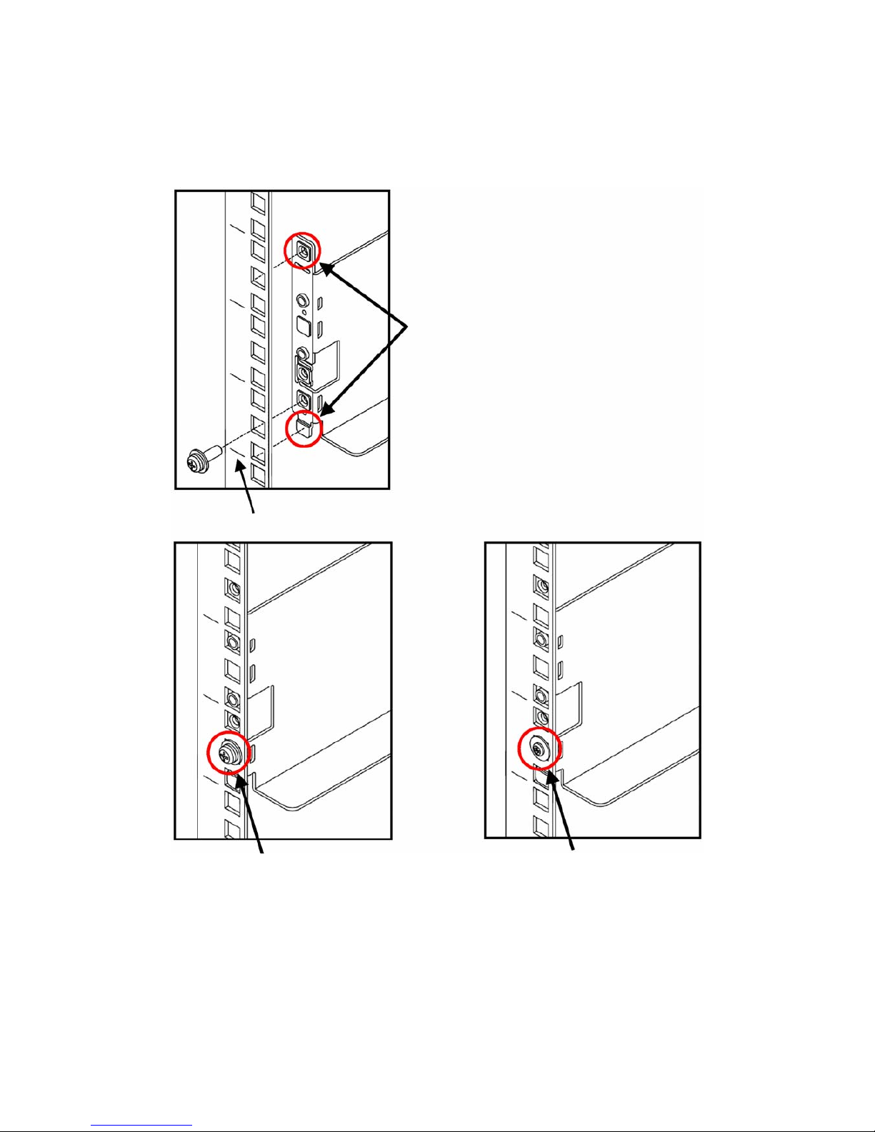
1. Align the bottom of the rail with the 1U mark and insert the top and bottom projections into
the holes on the front of the rack.
Insert the provided screw into the hole at the bottom to secure the rail.
If two small-head screws are provided, use them (as shown in the right figure below).
Insert
1U mark
Screw
Small-head screw
- 10 -
Page 28
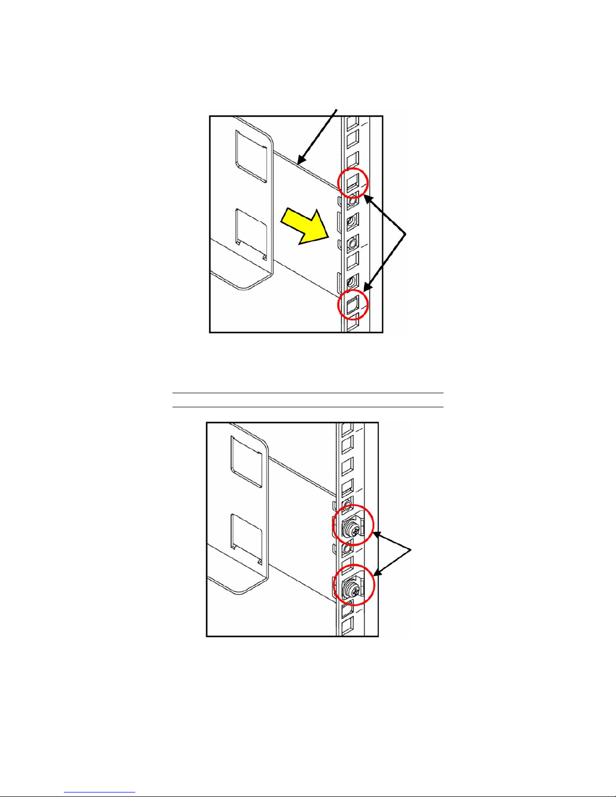
2. At the rear of the rack, pull the rail towards you and push the top and bottom projections into
the angle holes.
Inner
Insert
Figure 3.2.3 Rail Support (at the rear of rack)
3. Hold the inner rail, and push the two set screws with a part for cable clamp into the screw
holes of the rail support. Tighten the screws.
NOTE: Note the direction of the part for the cable clamp.
Tighten equally
Figure 3.2.4 Installing the Inner Rail on the Rack
- 11 -
Page 29
4. On the right side of the rack, install the other rail using the same procedure.
Figure 3.2.5 Installing Rail on the Right Side of the Rack
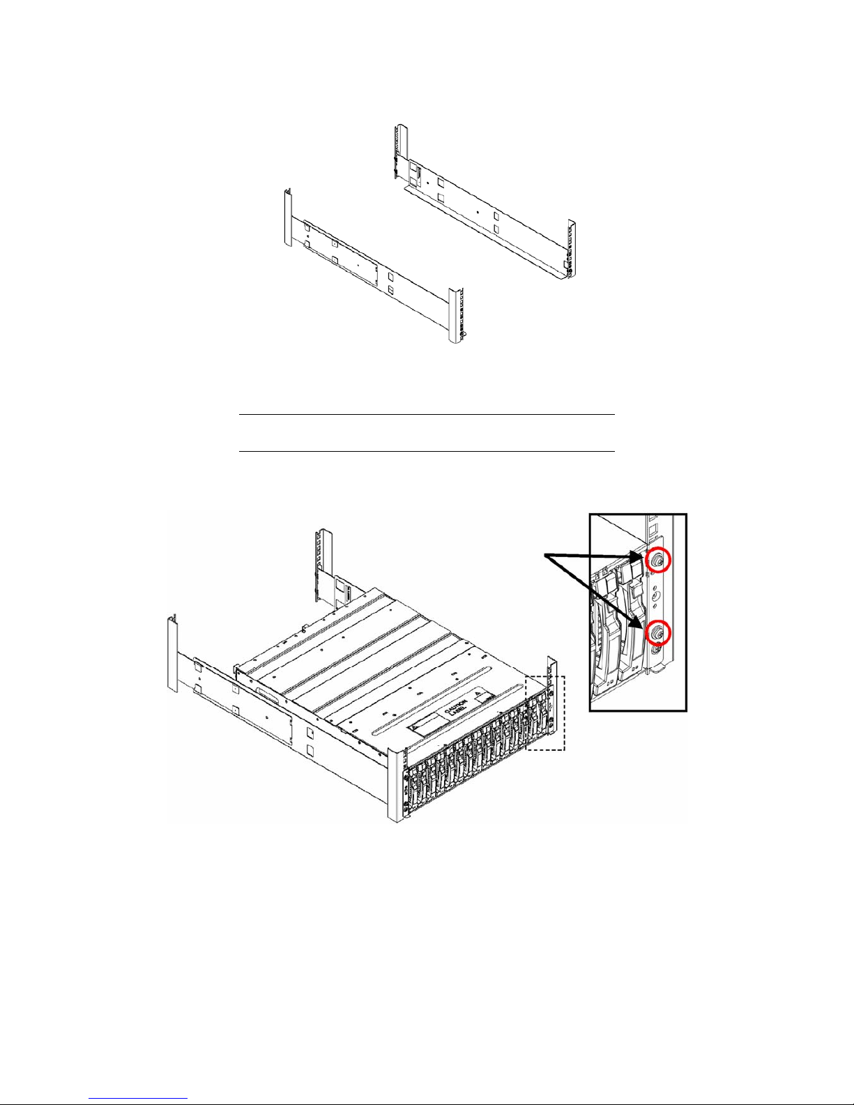
5. Lift the unit, put the rear section on the rails, and push it into the rack.
NOTE: The unit is very heavy. Be careful not to drop it while
you lift it.
Fasten the four set screws at the two left and two right points on the front of the unit. The
figure below only shows the right part of the unit. Fix the left part of the unit in the same way.
Screws
Figure 3.2.6 Installing the Unit in the Rack
- 12 -
Page 30
3.3 Connecting the Power Cords
The disk array unit, the FC disk enclosure, and the SATA disk enclosure all have a redundant power
configuration to prevent the entire unit from shutting down due to a single failure. Therefore, connect
a power cord to each power supply of the disk array unit, FC disk enclosure, and / or SATA disk
enclosure when operating the disk array unit.
3.3.1 Connecting AC Power Cords
3-3-1-1 Disk Array Unit
Use the AC power cord provided with the disk array unit.
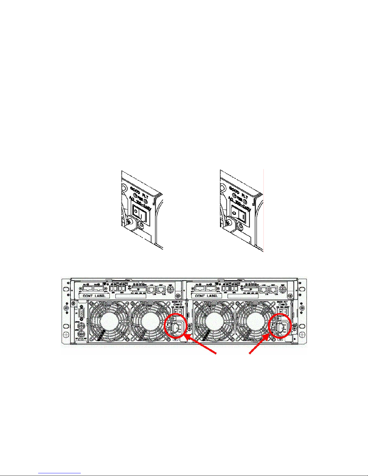
Make sure that the power switch is set to OFF, and take the following steps to connect the power cord.
1. Insert the plug of the AC power cord provided with the disk array unit to an AC outlet.
2. Secure the AC power cords with the AC cable clamp.
OFF ON
Power plugs
Figure 3.3.1 Rear View of the Disk Array Unit
- 13 -
Page 31

AC cable clamp
Figure 3.3.2 AC Cable Clamp
Locking mechanism of power cord
The locking mechanism of the power cord may differ from the one described in the User's Guide.
Connect or disconnect the power cord according to the procedure below.
Fasten
A
C cord
Open
Clamp section
- 14 -
Page 32

1. Installation
Extend the clamp section of the AC cable clamp, fit it to the AC cord, and lock the clamp
section lightly.
Then, move the clamp section towards the unit and position the clamp at a point near the end
of the plug. Securely lock the clamp section to avoid disconnection.
NOTE: A loose clamp may cause the accidental disconnection
of a power cord. Securely lock the AC clamp at a point near the
end of power cord.
2. Removal
Push the protrusion on the AC clamp (as shown in the figure below) to release the lock.
Remove the AC clamp from the power cord.
Cable clamp
Release
Protrusion
- 15 -
Page 33

3-3-1-2 FC Disk Enclosure /SATA Disk Enclosure
NOTES:
Skip this procedure if you have no additional FC or SATA
disk enclosures.
Use the AC power cord provided with the disk array unit.
Take the following steps to connect the two power cords.
1. Make sure that the power switch is set to OFF.
2. Insert the receptacle of the power cord provided with the disk array unit into the power plug
on the power supply.
3. Secure the power cords with the AC cable clamp.
OFF ON
Power plugs
Figure 3.3.3 Rear View of the Disk Enclosure
- 16 -
Page 34

AC cable clamp
Figure 3.3.4 AC Cable Clamp
- 17 -
Page 35

3.4 Setting the ENC ID Switch and Connecting the
HSSDC-HSSDC Cable
3.4.1 Adding a FC Disk Enclosure (Port DP0)
The connections and settings necessary for the addition of a FC disk enclosure are described below.
Skip this procedure if you will use the disk array unit without connecting a disk enclosure.
Set "1" for the ENC ID switches of the first disk enclosure (the DE nearest to the DAC). Then, set the
ENC ID switches of the other DEs to "2" and "3" in the connection order, as shown in Figure 3.4.1.
DE port 0 (DP0) DE port 0 (DP0)
Figure 3.4.1 Cable Connection Diagram
Connect the HSSDC-HSSDC cables provided with the disk enclosure as shown in Figure 3.4.1. Use an
available DE cable (optional) for the connection if all the disk enclosures cannot be installed in the
same rack.
- 18 -
Page 36

3.4.2 Adding a FC or SATA Disk Enclosure (Port DP1)
The connections and settings necessary for the addition of a FC or SATA disk enclosure are described
below. Skip this procedure if you will use the disk array unit without connecting a disk enclosure.
Set "0" for the ENC ID switches of the first FC or SATA disk enclosure (the DE nearest to the DAC).
Then, set the ENC ID switches of other DEs to "1" and "2" in the connection order, as shown in Figure
3.4.2.
DE port 0 (DP1
)
DE port 0 (DP1
)
Figure 3.4.2 Cable Connection Diagram
Connect the HSSDC-HSSDC cables provided with the FC or SATA disk enclosure as shown in Figure
3.4.2. Use an available DE cable (optional) for the connection if all the disk enclosures cannot be
installed in the same rack.
- 19 -
Page 37

3.5 Installing a FC/SATA Disk Drive
The disk drive has a plug-in structure. Insert the disk drive slowly.
Slowly and gently insert the disk drives one by one.
Use only brand new FC/SATA disk drives. The warranty does not apply when operating the
disk array unit using old or reused drives.
For installation and removal procedures, see Section 3.6 "Installation/Removal of Front
Panel".
Do not install any 1Gbps disk drives in the disk enclosure.
Do not mix SATA and FC hard disk drives in the same enclosure.
1. Remove the front panel, if installed.
2. Before installing the FC/SATA disk drive, select the location label appropriate to the location
where the FC/SATA disk drive is to be installed, and put it on the disk drive. The slots are
numbered from 0 to 14, from the left to the right of the unit when viewed from the front.
3. Lift the ejector of the FC/SATA disk drive upward to unlock it, and insert the FC/SATA disk
drive into the slot. Once the disk drive is securely inserted to the end, push down the ejector
until it locks into place.
4. Repeat steps 2 through 4 for each disk drive you wish to add.
- 20 -
Page 38

5. Install the front panel.
Location label
Location 00
Location 14
Figure 3.5.1 Installation of FC Disk Drive
Lift the ejector to remove the disk drive. Push down the ejector to install the disk drive.
Figure 3.5.2 Disk Drive Ejector
- 21 -
Page 39

3.6 Securit y Key and Front Panel
3.6.1 Locking/Unlocking with the Security Key
Turning the security key at the left of front panel to the vertical position locks the front panel (Figure
3.6.1). You can remove the key while the front panel is locked.
Turning the key to the horizontal position unlocks the front panel (Figure 3.6.2). You cannot remove
the key in the unlocked state.
Figure 3.6.1 Lock Figure 3.6.2 Unlock
3.6.2 Installing the Front Panel
Figure 3.6.3 Installing the Front Panel
In the unlocked state (Figure 3.6.2), push the bottom of the front bezel along the bottom of the unit.
- 22 -
Page 40

3.6.3 Removing the Front Panel
In the unlocked state (Figure 3.6.2), pull the left side of the front panel while using the right side as a
fulcrum.
Figure 3.6.4 Removing the Front Panel
- 23 -
Page 41

4. Connecting a PC for the Setup Wizard
4.1 Connecting a PC for the Setup Wizard
¾ To connect a PC to the disk array unit, the PC must include a 100/10Base interface and
Internet Explorer Version 5.0 or later.
¾ Connect the PC to the disk array unit in a direct one-to-one mode. Connection via a hub
may be possible, however, because the IP address and subnet mask are fixed,
connecting via a LAN (or such a kind of environment) may cause a malfunction to
occur.
¾ Set the following address to the PC on the network: 10.1.0.1/255.255.255.0.
For the setting, use the Internet protocol (TCP/IP). Remove any proxy setting if set.
¾ Use the MNT port of CONT0 (the right Ether port of CONT0 at the rear of the disk
array unit) for the connection.
IMPORTANT: MNT Port of CONT1 is not supported.
Connect the PC for the Setup Wizard only when it is to be used.
IMPORTANT:
Because the IP address and subnet mask of the MNT’s Ether
port are fixed as described above, do not connect the port to
any LAN or WAN.
The amber LED at the lower left of the Ether port lights
while in the TCP connection state.
CONT1 CONT0
PC for Setup Wizard (MNT
0 port)
Figure 4.1.1 Rear View of the Disk Array Unit
- 24 -
Page 42

IMPORTANT: LAN cable for PC for Setup Wizard
Use a shielded (STP/FTP only) cross-over cable to connect
the unit directly to the terminal.
Use a shielded (STP/FTP only) straight cable to connect the
unit to the terminal via a hub.
a. Direct connection
MNT port
Cross-over cable
Straight cable
b. Connection via a hub
MNT port
Straight cable
Figure 4.1.2 Connection Diagram of a PC for the Setup Wizard
- 25 -
Page 43

4.2 Powering-on
Take the following steps to power on the unit, and provide the initial setup using the Setup Wizard.
1. First power on the DE, if connected.
Then, power on the DAC.
Turn ON all the power switches located at the rear of the DAC and DE (if connected). (You
can turn on either one of the two switches first, but they cannot be turned on simultaneously.)
2. As the disk drive starts, and the Ready LED on the disk drive goes on, the SERVICE LED on
the front of DAC will flash for a few minutes, and then go off.
Only the front POWER LED remains lit when the unit is ready.
3. Make sure that both the SVP LED and DIR LED at the rear of the DAC are flashing.
When the unit reaches a Ready Status, proceed to Chapter 5.
SHUTDOWN switch POWER LED SERVICE LED
Figure 4.2.1 Front View of the Disk Array Unit
A front bezel is installed on the front face of the disk array unit as shown in Figure 4.2.1.
Once the front bezel is removed, you can view the disk drives as shown in Figure 4.2.2.
SERVICE LED POWER LED
SHUTDOWN switch
Ejector
Hard disk drive FAULT LED
Hard disk drive READY LED
Disk drive / dummy tray
Figure 4.2.2 Disk Drives
- 26 -
Page 44

Figure 4.2.3 is an enlarged view of the controller at the rear of the disk array unit.
FLT LED
BAT LED
DIR LED
SVP LED
Enlarged view
Figure 4.2.3 Rear View of the Disk Array Unit
- 27 -
Page 45

4.3 Powering On/Off the Disk Array Unit
This section describes how to turn on or off the power of the disk array unit. Turning on or off the
power carelessly may cause some data to be corrupted, some software to operate incorrectly, and/or
the unit to become defective.
Turning on AC power
a) Before turning on the power, push each hard disk drive to make sure they are all fully
inserted.
b) Turn on both power switches on the rear of the disk array unit.
If an additional disk enclosure is connected, first turn on the two power switches on the rear
of the additional disk enclosure, and then turn on the two power switches on the rear of the
disk array unit. Alternatively, turn on the disk array unit and all the additional disk enclosures
connected with the disk array unit at the same time.
The disk array unit and additional disk enclosure have a redundant power configuration to
prevent the entire unit from shutting down due to a single failure. Therefore, when turning on
the disk array unit, turn on all the power switches (of the disk array unit and additional disk
enclosures) at the rear of the unit.
When turning on the power switches, confirm that the POWER GOOD LED (green) of the
power supply and the POWER LED (green) on the front panel of the disk array unit and the
additional disk enclosure(s) light on. Power supply starts, and the POWER LED (green) is on
while the power switches are on.
The disk array unit performs the self-test and initialization sequence immediately after the
power is turned on. When the self-test and initialization terminate and the disk array unit
becomes ready, the DIR LED of the controller on the disk array unit stops lighting and starts
flashing. Confirm the DIR LED status, and then turn on the host system.
The disk array unit takes 15 minutes (at maximum) to start.
- 28 -
Page 46

[Power-on procedure]
Turn on the power switches in the following order (1) to (3):
(1) additional disk enclosure power switches
(3) Host System
(2) Disk array unit power switches (May be turned on at the same time than the power switches of any
additional FC disk enclosures.)
Figure 4.2.4 Power-on procedure
- 29 -
Page 47

Notes on turning off AC power
The disk array unit periodically writes data in the cache memory onto a disk drive. If you turn off the
AC power before completion of this write to the disk drive, the remaining data in the cache memory is
preserved up by the battery backup units.
However, the preservation time is limited. (The preservation time depends on the number of installed
battery backup units, the capacity of cache memory, and the battery’s charge status. See Section 2.2
"Write Cache Feature" for details.). To securely protect data, write all the data remaining in cache
memory in the disk array unit onto the disk drive according to the following procedure. Then turn off
the AC power according to the procedure explained in "(3) Turning off AC power".
1. Turn off the power of the host system and the host bus adapter or the FC-AL switch.
Alternatively, offline all the paths connected to the host system that is connected with the disk
array unit.
2. Push the SHUTDOWN switch located on the front of the disk array unit by using the stick
attached to the key for at least 5 seconds.
Make sure that the POWER LED starts flashing,, and release the stick from the switch.
Figure 4.2.5 SHUTDOWN switch
3. Confirm that the [POWER LED] on the front panel of the disk array unit goes off, and then
turn off the AC power according to the procedure explained in "(3) Turning off AC power".
As long as the [POWER LED] lights or flashes, the data in the cache memory is being written
onto the disk drive; DO NOT turn off the AC power.
NOTES:
If you turn off the AC power of the disk array unit during a
write operation (with the POWER LED flashing) by mistake,
the system enters the backup mode. Turn on the AC power
of the entire disk array unit again. When the disk array unit
has started, push down the SHUTDOWN switch to complete
the write operation.
Writing cache data onto a disk drive takes a maximum of10
minutes.
- 30 -
Page 48

IMPORTANT:
When the host system is shut down, it writes the remaining
cache data into the disk array unit. The cache data remaining
in this host system is written into the disk array unit. Before
turning OFF the power, confirm that no cache data remains
on the host system and no data remains in the cache memory
on the disk array unit.
To check if data remains in the cache memory on the disk
array unit, watch the hard disk drive READY LED after
shutting down the host system. If the hard disk drive
READY LED is flashing, data remains in the cache memory
on the disk array unit. It takes a maximum of about 10
minutes to write the remaining data from the cache memory
to the disk drive.
Turning off the AC power
a) To turn off the power, turn off the host system or the FC-AL switch, and then perform the
procedure shown in "(2) Notes on turning off the AC power".
b) Turn OFF the two power switches on the rear of the disk array unit. If an additional disk
enclosure is connected, turn OFF the two power switches on the rear of the disk array unit,
and then turn OFF the two power switches on the rear of the additional FC or SATA disk
enclosure. Alternatively, you can also turn OFF all the power switches on the disk array unit
and the additional disk enclosure at the same time.
The disk array unit has a redundant power configuration to prevent the entire unit from
shutting down due to a single failure. Therefore, when turning off the disk array unit, turn off
all the power switches (of the disk array unit and additional disk enclosures) at the rear of the
unit.
Be aware that you can lose data if you turn off the additional disk enclosures before the disk
array unit.
- 31 -
Page 49

[Power-off procedure]
Turn off the power switches in the following order (1) to (3):
(1) Host system
(3) The power switches of additional disk enclosures may be turned off at the
same time the power switches of disk array unit are turned off.
(2) Disk array unit power switches
Figure 4.2.6 Power-off procedure
- 32 -
Page 50

5. Configuration using the Setup Wizard
5.1 Start Procedure
Insert the Setup Wizard CD-ROM into the CD-ROM drive of your PC.
The Setup Wizard starts automatically.
If the Setup Wizard does not start automatically, open the Explorer and double-click the file below.
CD-ROM drive:\SetupWizard\SetupWizard.exe
During the Setup Wizard, provide the configuration according to the information displayed in the
dialog boxes.
- 33 -
Page 51

5.2 Initialization
Your system was initialized at the factory. We recommend you only make changes to the system
configuration, and do not perform the initialization process at your side.
5.3 System Configuration Change
The configuration of the disk array unit can be changed according to the procedures described below
when it is required due to a system change or for some other reason. The network configuration and
license unlocking are enabled by the WebSAM NEC Storage Manager.
To change from the disk array controller of the single controller model to that of the dual controller
model, first confirm that Controller 1 is activated normally (the DIR LED blinks regularly) and then
start the Setup Wizard to provide [Host port configuration] and [Network configuration] in [System
configuration change or Addition]
Start dialog
Confirm that the target disk array unit is correct.
See "5.3 (1) St art dialog" for details.
Selection
Select the configuration change mode and specify the terms that
require changing. See "5.3 (2) Selection".
Configuration
Confirm that the settings preparation is completed.
See "5.3 (3) Configuration" for details.
Host Port
Configuration
Set the port connection platform and FC port information.
See "5.3 (4) Host Port configuration" for details.
Disk Enclosure Unit
Configuration
Set the FC and/or SATA disk enclosure information.
See "5.3 (5) Disk Enclosure Unit Configuration" for details.
Confirms that
the Disk Enclosure
Confirm the connection of the FC and/or SATA disk en closure.
See "5.3 (6) Confirmation that the Disk Enclosure" for details.
Network
configuration
Set the disk array unit network information.
See "5.3 (7) Network configuration" for details.
Confirmation and
adaptation of
configuration
Confirm that the settings contents are correct and upload the
configuration. See "5.3 (8) Confirmation of configuration" and "5.3 (9)
Uploading the configuration" for details.
Configuration
Completed
Confirm that the configuration is correct.
See "5.3 (10) Configuration completed" for details.
If the configuration fails, check the status of the disk array unit.
See "5.3 (11) Failure in configuration" for details.
- 34 -
Page 52

(1) Start dialog
The Setup Wizard dialog box appears. Check the information and click on Next.
(2) Selection
Select the configuration mode of the Setup Wizard.
Select "System configuration change or Addition" to change the configuration change.
Check the term(s) to be configured. The dialog(s) box(es) of the term(s) that do not require checking
are omitted.
- 35 -
Page 53

Host Port Configuration
Check this term when you change the port connection configuration.
See "5.3 (4) Port connection configuration" for details.
Disk Enclosure Unit Configuration
Check this term when you change the disk enclosure configuration.
See "5.3 (5) Disk enclosure unit configuration" for details.
Network Configuration
Check this term when you change the network configuration.
See "5.3 (7) Network configuration" for details.
NOTE: You cannot go to the next dialog box if you do not
check at least one of these terms. To go to the next dialog box,
check one or more terms or select [Initialization].
(3) Configuration
Confirm the displayed information before proceeding further.
(4) Host Port Configuration
Select the platform and connection type of the host system to which the port is connected.
- 36 -
Page 54

IMPORTANT: To connect to a switch made by Brocade
Communications Systems, Inc., set the parameters to
“Windows/Brocade FC Switch” or “Linux/Brocade FC Switch”.
(5) Disk Enclosure Unit Configuration
Set the information regarding the optional FC and/or SATA disk enclosures (DEs).
If no DE is attached, select "No attached Disk Enclosure".
When one or more DEs are attached, select "Attached Disk Enclosure Units" and enter the number of
attached DEs.
- 37 -
Page 55

(6) Disk Enclosure Confirmation
If you selected [No attached Disk Enclosure] in the step (5) Disk enclosure unit configuration, this
dialog box does not appear. Go to (7) Network configuration.
If you selected [Attached Disk Enclosure Units], a specific confirmation dialog box appears depending
on the number of disk enclosures.
Check the connections of the FC and SATA disk enclosures. Confirm that the each FC and SATA disk
enclosure is connected correctly and that each ENC ID is set correctly.
IMPORTANT: Always turn off the power switches of the disk
array unit and of any FC and SATA disk enclosures before you
change ENC IDs and/or cable connections.
- 38 -
Page 56

In the case of a single attached disk enclosure:
In the case of three attached disk enclosures, or two FCs and a single SATA:
- 39 -
Page 57

(7) Network configuration
Set the network information for the disk array unit.
Specify a valid value
other than 10.1.0.0 or
10.1.0.255
If a single controller
connection is selected,
you can only modify
the Controller 0
network configuration.
Set it to 0.0.0.0. if
you have no
gateway address
to specify.
Specify a valid value
other than 10.1.0.0 or
10.1.0.255
Set it to 0.0.0.0. if
you have no
gateway address
to specify.
Watch Server Setting
Select the “Watch Server” when you wish to allow access only to specific WebSAM NEC
Storage Manager servers (commands coming from an IP address different than the ones
specified are not accepted).
The Watch Server setting dialog box specifying IP addresses appears.
Up to eight IP addresses can be specified.
[Watch server configuration dialog]
Select this if you do not wish to restrict access.
Commands issued by any WebSAM NEC
Storage Manager servers (regardless of their
IP Addresses) will be accepted.
Select this if you wish to
grant access to specific
WebSAM NEC Storage
Manager servers.
- 40 -
Page 58

[IP address specification dialog]
Specify the IP address to
be added or changed.
(8) Configuration Confirmation
The configuration data to be set to the disk array unit appears. Confirm the setting of each term.
To change the settings contents, select the [Return] button to return to the relevant dialog box.
NOTE: File names are automatically determined and based on
the current date and time.
- 41 -
Page 59

Display of the settings contents
Target Disk Array
Displays the definition information of the disk array unit targeted by the Setup Wizard.
– Disk Array
Indicates the target disk array unit.
– IP Address
Indicates the IP address used to try communication.
An asterisk [*] marks the IP address used for communication.
[Example]
--------------------- Target Disk Array ---------------------Disk Array: NF0500-SR40P42
IP Address: *10.1.0.10
10.1.0.11
Parameter List
Indicates the settings contents of each item.
<Configuration mode>
Indicates the Setup Wizard mode.
Mode
Indicates the Setup Wizard mode.
If [System configuration change or addition] is selected, the following terms also appear to
specify whether they have been changed or not.
– Port connection configuration
– Disk enclosure configuration
– Power control configuration
[Example]
------------------------- Parameter List -------------------------<Configuration mode>
Mode: Initialization
------------------------- Parameter List -------------------------<Configuration mode>
Mode: System configuration change and Addition
- Port connection configuration: Changed
- Disk enclosure configuration: Not changed
- Power control configuration: Changed
- 42 -
Page 60

<Host port configuration>
Indicates the host port configuration settings contents.
– Controller0
Indicates the settings contents of the port on Controller0.
– Controller1
Indicates the settings contents of the port on Controller1.
[Example]
<Host port configuration>
Controller0
- HP0 : Windows/Server
- HP1 : Windows/FC Switch
Controller1
- HP0 : Windows/ Server
- HP1 : Windows/FC Switch
– Connect to MSCS configuration or NEC Express5800/ft server.
Indicates whether a connection exists to the MSCS configuration or NEC Express5800/ft
server.
[Example]
Connect to MSCS configuration or NEC Express5800/ft server: No
Connect to MSCS configuration or NEC Express5800/ft server: Yes
<Disk enclosure configuration>
Indicates the disk enclosure configuration settings.
– Attached disk enclosure
Indicates whether one or more disk enclosures are attached (and how many if there are
some).
[Example]
<Disk enclosure configuration>
Attached disk enclosure: No
< Disk enclosure configuration >
Attached disk enclosure: Yes (2)
- 43 -
Page 61

<Network configuration>
Indicates the network configuration settings contents.
– Mode
Indicates the network lines that are used.
– Controller0
Indicates the Controller0 settings.
IP address
Subnet mask
Gateway address
– Controller1
Indicates the Controller1 settings.
Appears when the mode specification is [Used in two lines]
IP address
Subnet mask
Gateway address
[Example]
<Network configuration>
Mode: Used in single line (Controller0)
Controller0
- IP address: 10.1.1.1
- Subnet mask: 255.255.255.0
- Gateway address: 0.0.0.0
< Network configuration >
Mode: Used in two lines (Controller0/1)
Controller0
- IP address: 10.1.1.1
- Subnet mask: 255.255.255.0
- Gateway address: 0.0.0.0
Controller1
- IP address: 10.1.1.2
- Subnet mask: 255.255.255.0
- Gateway address: 0.0.0.0
- 44 -
Page 62

Watch server configuration
Indicates the access configuration settings for the WebSAM NEC Storage Manager server.
If [Accepts from the following IP address] is selected, the IP address appears.
– IP address
Indicates the IP address of the WebSAM NEC Storage Manager server accepting watch.
[Example]
Watch server configuration: Accepts from any IP address.
Watch server configuration: Accepts from the following IP address.
- IP address: 192.168.0.1
192.168.1.1
Watch server configuration: The IP address to be accepted is not set yet.
<License configuration>
Indicates the license unlock configuration settings.
– License key
Indicates the basic control license key you entered for your SystemGlobe NEC Storage.
[Example]
<License configuration>
License key: SLKCIK - GOEIKS - JKOLHJ - SKSJEJ - HNJMSX
- 45 -
Page 63

(9) Uploading the configuration
Sends the information to the disk array unit.
When you press [Next] on the [Confirmation of the Configuration] dialog box, a message prompts you
for confirmation before sending the configuration information.
OK
Sends the configuration to the disk array unit.
The settings contents are saved in a file.
Cancel
Cancels the upload.
This status message appears during the uploading of the configuration.
NOTE: When the outputting of the settings contents to a file
fails, the message shown below appears.
Be sure to specify a folder with a large enough capacity for the
outputting of data to files, and for which you have access rights.
See "(8) Confirmation of configuration" for how to change a
storage folder.
- 46 -
Page 64

(10) Configuration completed
If the disk array unit is configured correctly, the following dialog box appears.
Click [Finish] to exit the Setup Wizard.
- 47 -
Page 65

(11) Configuration Failure
If the configuration of the disk array unit fails, the following dialog box appears.
Failure when downloading the information from the disk array unit
Example)“License Key entry” error.
NOTE: Major confirmation terms
Is the disk array unit targeted by the Setup Wizard for
configuration?
Is the network configuration of the PC (including the IP
address, subnet mask and gateway address) correct?
Are you using an Ethernet cable of the correct type (straight
or cross-over)?
Is the Ethernet cable disconnected or loose?
- 48 -
Page 66

6. Installing WebSAM NEC Storage Manager Server
and Client
6.1 Connecting the WebSAM NEC Storage Manager Server
(through LAN cable)
The WebSAM NEC Storage Manager is a software product indispensable for using the NEC Storage
S1500.
The NEC Storage server can be connected to CONT0/1. When only 1 controller is connected, use
CONT0.
We recommend you specify a different Ethernet Port IP for each controller in order to take advantage
of the redundant configuration when using an Ethernet Hub.
CONT0
CONT1
LAN ports for WebSAM NEC Storage
Manager servers
Figure 6.1.1 Rear view of the disk array unit
NOTE: LAN cable used to connect to the NEC Storage server
Use a shielded cross-over cable (STP/FTP only) to connect
the NEC Storage server to a PC directly.
Use a shielded straight cable (STP/FTP only) to connect the
NEC Storage server to a PC via a hub.
- 49 -
Page 67

6.2 Installing the WebSAM NEC Storage Manager Server and
Setting up the Environment
Install the WebSAM NEC Storage Manager as described in the following procedure.
Refer to the "NEC Storage Manager Installation Guide" and the "NEC Storage Manager User's
Manual" for details.
The "NEC Storage Manager Installation Guide" and "NEC Storage Manager User's Manual" are stored
on the WebSAM NEC Storage Manager CD-ROM in the form of .pdf files.
NOTES:
To use the NEC ESMPRO link feature, install NEC
ESMPRO Agent before WebSAM NEC Storage Manager.
Close any service ran by the AlertManager Main Service in
order to secure the registration of the link feature, and
perform the installation procedure.
When you try to install the WebSAM NEC Storage Manager
to an NEC Express5800 server in which the ESMPRO
Manager is already installed, a dialog box appears which
asks whether the ESMPRO AlertManager is to be linked.
Establish the link if necessary. For details of the WebSAM
NEC Storage Manager, see "Link between ESMPRO
Manager and ESMPRO Alert Manager" in the "NEC Storage
Manager User's Manual".
The WebSAM NEC Storage Manager creates many files in
the installation folder while it operates. During an
uninstallation, the files stored in the installation folder
(including sub-folders) are to be deleted except the
WebSAM NEC Storage Manager server configuration file
and some others. Accordingly, it is recommended to select
the default folder as the installation folder.
To use a folder other than the default, create a new folder or
select a folder which does not contain any files. Do not save
important files in the installation folder and sub-folders
subordinate to the folder.
The installation folder cannot be a folder including a Win.ini
file.
- 50 -
Page 68

1. Log in to the system as an Administrator.
2. Select [Control Panel] → [Add or Remove Applications] ([Add or Remove Programs] for
Windows Server 2003). Select the following installation program:
CD-ROM Drive: \install\StorageManager_Ver4.2E\Server\Windows\setup.exe
3. Follow the directions of the installer.
When installing the WebSAM NEC Storage Manager to an NEC Express5800 server in
which the NEC ESMPRO Manager is already installed, see the second paragraph in "Notes"
described above.
Proper environment settings are required to start the WebSAM NEC Storage Manager server.
Provide the environment settings during the installation.
See "6.2.1 Environment Settings of WebSAM NEC Storage Manager Server" for the
environment settings.
4. After the environment settings are completed, restart the system.
To prevent the WebSAM NEC Storage Manager from starting automatically when the system
restarts, see "Server Start/Stop" in the "NEC Storage Manager User's Manual".
- 51 -
Page 69

6.2.1 Environment Settings of WebSAM NEC Storage Manager Server
Proper environment settings are required to start the WebSAM NEC Storage Manager server.
This section describes how to set the items required to monitor the disk array unit.
For other items, refer to the "NEC Storage Manager Installation Guide".
6-2-1-1 Setting Disk Array Information
The disk array information (including the identification of the disk array unit to be
monitored by the WebSAM NEC Storage Manager server) can be set using the following
environment setting dialog boxes.
After the WebSAM NEC Storage Manager server is installed, the following dialog box
appears.
If the dialog box does not appear, select [Start]
→ [Programs] ([All Programs] for Windows
Server 2003)
→ [WebSAM NEC Storage Manager Server] → [Environment Settings] or
[Environment Settings] in the WebSAM NEC Storage Manager Server Menu.
When the Setting Utility dialog box shown below appears, press the [Add] button.
Figure 6.2.1 Disk array list tab
- 52 -
Page 70

Specify the IP address set in "5.2 (7) Network configuration". Enter the IP address of CONT0
in the Main IP Address and that of CONT1 in the Sub IP Address.
Figure 6.2.2 Disk array addition dialog box 2
- 53 -
Page 71

6-2-1-2 Setting User Information
Define the user to be used for the connection from the WebSAM NEC Storage Manager client.
The user information is the account required to view or manipulate the disk arrays information in the
WebSAM NEC Storage Manager client to which the WebSAM NEC Storage Manager server is
connected.
The user information consists of three items, User Name, Password and User Level (see the
description of the user addition dialog box shown later for details).
The default user is registered as follows: User Name is iSM, Password is iSM and User Level is L1
(information view only permitted).
This Setup Guide describes the initial setting from the NEC Storage to the disk array unit. To do that,
be sure to add a user registered with a User Level L3.
The user information can be set on the following Environment Settings dialog box(for users).
First select [Start]
→ [Programs] ([All Programs] for Windows Server 2003) → [WebSAM NEC
Storage Manager Server]
→ [Environment Settings] or [Environment Settings] in the WebSAM NEC
Storage Manager Server Menu.
If you change one or more settings, restart the WebSAM NEC Storage Manager server afterwards. The
information set on each dialog box is saved when you press [OK].
1. Click the [Add] button on the [Users] tab.
Figure 6.2.3 User list box
- 54 -
Page 72

2. Enter the relevant data in the [User Name], [Password] and [Password Confirmation] fields,
and select a proper User Level. Click on [OK].
Figure 6.2.4 Add User dialog box
3. When prompted to do so, click on [Yes].
Figure 6.2.5 Message confirming that the set up information has been saved
- 55 -
Page 73

6.3 Installing the WebSAM NEC Storage Manager client and
Setting up the Environment
6.3.1 Installing the WebSAM NEC Storage Manager Client
Install the WebSAM NEC Storage Manager client on a PC as described below. Refer to the "NEC
Storage Manager Installation Guide" for details.
1. Log in to the system as an Administrator.
2. Select [Control Panel] → [Add or Remove Applications] ([Add or Remove Programs] for
Windows XP/Windows Server 2003). Then select the installation program. The installation
program is stored in the location below:
CD-ROM drive:\
install\StorageManager_Ver4.2E\Ism client\Windows\Isce4202.exe
3. Follow the on-screen instructions.
The default installation value is subordinate to the system drive "Program
files\NEC\iSMClient".
4. If the NEC ESMPRO Manager (abbreviated as ESMPRO/SM hereafter) has already been
installed prior to the installation of the WebSAM NEC Storage Manager client, the message
box [ESMPRO setting] appears.
To add [Storage Manager Client Start] in the tool menu of the EMSPRO/SM operation
window, click the [Yes] button. Click [No] if you do not wish to do so.
Figure 6.3.1 Registration of WebSAM NEC Storage Manager Client Item
- 56 -
Page 74

5. To install the WebSAM NEC Storage Manager client in an environment with the NEC
ESMPRO Manager installed, a dialog box asking whether it is linked to the WebSAM Alert
Manager appears.
Provide the proper settings if necessary. See "1.7.4 Link between ESMPRO Manager and
ESMPRO Alert Manager" in the "NEC Storage Manager User's Manual" for details.
6. After the installation of the WebSAM NEC Storage Manager client, some settings are
required on the Environment Settings dialog box.
See "6.3.2 (2) Setting Environment" for the Environment Settings.
See "Client Start/Stop" in the "NEC Storage Manager User's Manual" and the Help section of
the WebSAM NEC Storage Manager client for details.
- 57 -
Page 75

6.3.2 Starting the Client
1. Starting the Client
Select [Start]
→ [Programs] ([All Programs] for Windows XP/Windows Server 2003) →
[iSM Client]. The WebSAM NEC Storage Manager client starts, displaying the main window.
If you define more than one connection target, a menu appears in [iSM Client Connection
Target Name], confirm the connection targets with their nicknames and start the WebSAM
NEC Storage Manager client.
Once the client has started, go to "(2) Setting Environment settings" and "(3) Connection".
2. Environment settings
At the first start of the WebSAM NEC Storage Manager client (depending on the directions
of the installer) a dialog box indicating that the environment settings are not provided yet
appears (see Figure 6.3.2). If the environment settings are not provided yet or if a connection
target has been added, select [File]
→ [Environment Settings] to display the Environment
Settings dialog box.
Figure 6.3.2 Dialog box indicating environment settings are not provided yet
- 58 -
Page 76

Figure 6.3.3 Environment Settings dialog box
If you select the connection target to be subject to environment settings and press the [Edit]
button, the following Environment Settings dialog box appears. Enter proper values in the
required fields, including [Connection Name], [IP Address or DNS Name of Server], and
[Client Name]. Once the settings are completed, press [OK] to save the setting information.
Figure 6.3.4 Environment Settings dialog box
- 59 -
Page 77

– Connection Name
Enter the nickname identifying the connection target. (This is mandatory if more than
one connection targets are specified.)
The specified connection name appears on the title bar of each dialog box of the client.
When more than one client is started, the title bar displays the connection name,
allowing you to identify the server sending the information.
– IP Address or DNS Name of Server
Enter the IP address or DNS name of the NEC Storage server.
– Client Name
Enter the name identifying a specific client.
This can be any alphanumeric character string as long as it is unique.
3. Connection
Selecting [File]
→ [Connection] after the environment settings establishes the actual
connection with the NEC Storage server.
If [Connection] cannot be selected, first select [File]
→ [Disconnection] and then select [File]
→
[Connection] again.
Figure 6.3.5 Connection dialog box
- 60 -
Page 78

– User Name
Enter the user name registered in the NEC Storage server. See "6-2-1-2 Setting User
Information".
– Password
Enter the password registered in the NEC Storage server. See "6-2-1-2 Setting User
Information".
All the user names and passwords can be saved. However, note that anyone can connect
if you save a password with a login.
When you press [OK], the current disk array configuration appears in the Configuration
Information dialog box and sequential messages appear in the Fault Watch dialog box.
- 61 -
Page 79

6.4 NEC Storage Settings
At least the following items must be set in the NEC Storage.
For more information, refer to the "NEC Storage Manager Configuration Setting Tool User's Manual
(GUI)" saved on the WebSAM NEC Storage Manager CD-ROM as a .pdf file.
6.4.1 License Key Registration (for other than the Base Product) <If Used
Only>
The following screen (displayed by selecting [Configuration Setup Menu] → [Disk Array Setting] →
[License]) allows you to unlock or view the licenses of purchased products.
Figure 6.4.1 Status Screen
Figure 6.4.2 Select Operation Mode dialog box
- 62 -
Page 80

Figure 6.4.3 Setting mode inquiry message
Figure 6.4.4 Setting Mode dialog box
- 63 -
Page 81

Figure 6.4.5 License key entry dialog box
Enter the license key (thirty alphanumeric characters) specified on the purchased disk array product
(6-6-6-6-6) and press the [Unlock] button. Click the [Yes] button to unlock the license.
- 64 -
Page 82

6.4.2 Pool Binding
To provide pool binding, specify the physical disks used to configure a RAID from among the physical
disks installed in the disk array unit and the RAID type. Next, you can do the logical binding. Pools
are divided into two types; a dynamic pool allowing the expansion of the pool and logical disk
capacities, and a basic pool for which expansions are disabled.
Any of the following logical disk configurations can be selected. Specific logical disk configurations
are possible in pools.
Dynamic pool RAID6 (4+PQ)/(8+PQ)
Basic pool RAID1 (1+1)
Basic pool RAID5 (4+P)
Basic pool RAID10 (1+1)×2/(1+1)×3/(1+1)×4/(1+1)×5/(1+1)×6/
(1+1)×7/ (1+1)×8
Logical disk
configuration:
Basic pool RAID50 (4+P)×2/(4+P)×4
Logical disk binding should be done using the procedure below:
1. Pool binding
2. Logical disk binding
Pool binding can be done using the Wizard. Follow the on-screen instructions to set the new
binding pool.
- 65 -
Page 83

1. Starting the Pool Binding Wizard
Select [Configuration Setting Menu] → [Disk Array Setting] to display the Logical Disk
Bind/Unlock screen. On the screen, press the [Pool Binding] button.
Figure 6.4.6 Status display screen
Figure 6.4.7 Select Operation Mode dialog box
- 66 -
Page 84

Figure 6.4.8 Setting Mode dialog box
Figure 6.4.9 Activating Pool Binding Wizard
- 67 -
Page 85

2. Starting the Pool Binding Wizard
When you press the [Pool Binding] button on the [LD Individual Bind/Unbind] dialog box.
The [Pool Binding Wizard] dialog box appears. Press [Next].
Figure 6.4.10 Starting Pool Binding Wizard
3. Selecting the Pool selection
When you press [Next], the [Pool Selection] dialog box appears. Select the pool type for
binding and press [Next].
Figure 6.4.11 Pool selection
- 68 -
Page 86

4. Selecting the RAID type
When you press [Next] on the [Pool Selection] dialog box, the [RAID Type Selection] dialog
box appears.
Select the RAID type of the pool for binding. The options vary depending on the type
selected in the [Pool Selection] dialog box. Select a RAID type and press [Next].
Figure 6.4.12 RAID type selection (dynamic pool)
Figure 6.4.13 RAID type selection (basic pool)
- 69 -
Page 87

5. Selecting a Physical disk
When you press [Next] on the [RAID Type Selection] dialog box, the [PD Selection] dialog
box appears.
Select one or more physical disks used for pool binding from the unused disks and press the
[Add] button. The selected physical disks are added to the pool binding disk list. Once the
physical disks are added, press [Next].
Figure 6.4.14 Physical disk selection
6. Setting the detail parameters
When you press [Next] on the [PD Selection] dialog box, the [Detail Parameter Setting for
Pool Binding] dialog box appears.
Enter the pool name and press [Next].
Figure 6.4.15 Pool parameter setting for pool binding
- 70 -
Page 88

7. Confirming the pool binding parameters
When you press [Next] on the [Detail Parameter Setting for Pool Binding] dialog box, the
[Configuration for Pool Binding Parameter] dialog box appears.
Confirm the parameters and press [Next].
The pool binding inquiry message appears. Press [Yes].
Figure 6.4.16 Confirmation for pool binding parameter
Figure 6.4.17 Pool binding inquiry message
- 71 -
Page 89

8. Pool Binding Complete
If the pool binding succeeds, the following dialog box appears. Press [Finish] to exit the
Wizard.
Figure 6.4.18 Pool Binding Complete
- 72 -
Page 90

6.4.3 Logical Disk Binding
Logical disk binding can also be done using the Wizard. Follow the on-screen instructions to bind the
logical disks in a specified pool.
See Chapter 6 of the "NEC Storage Manager Configuration Setting Tool User's Manual (GUI)" for
details.
1. Starting the Logical Disk Binding Wizard
Press the [LD Binding] button on the [LD Individual Bind/Unbind] dialog box shown below.
Figure 6.4.19 LD Individual Bind/Unbind dialog box
- 73 -
Page 91

When you press the [LD Binding] button on the [LD Individual Bind/Unbind] dialog box, the
[LB Binding Wizard] dialog box appears. Follow the on-screen instructions to bind logical disks.
Press [Next].
Figure 6.4.20 Starting LD Binding Wizard
2. Selecting a Pool
When you press [Next] on the [LD Binding Wizard] dialog box, the [Pool Selection] dialog
box appears.
Figure 6.4.21 Pool selection
Select in the list the pool in which you wish to bind logical disks.
If a pool has an asterisk (*) in a free capacity field, it means that more than one Free Area
exist in this pool. (The asterisk appears when the Free Area in the basic pool is fragmented
because one or more logical disks were deleted).
3. Free Area selection
- 74 -
Page 92

If you select a pool including more than one free area and press [Next] in the [Pool Selection]
dialog box, the [Free Area Selection] dialog box appears.
Select in the Free Area list an area in which a logical disk is to be bound and press [Next].
Figure 6.4.22 Free Area Selection
4. Binding method specification
When you press [Next] on the [Free Area Selection] dialog box, the [Binding Method] dialog
box appears.
When you select a pool including only a single Free Area or a pool belonging to a dynamic
pool and press [Next], this dialog box appears.
Select any of the following logical disk binding methods and press [Next].
Figure 6.4.23 Specifying binding method
- 75 -
Page 93

5. Specifying the number of logical disks and their capacities
a. Specifying the number of logical disks
When you specify only the number of logical disks on the [Binding Method] dialog box
and press [Next], the [Specifying Number of LDs] dialog box appears.
Specify the number of logical disks for binding and press [Next].
Each logical disk for binding has the capacity noted in 1 GB increments. The maximum
available capacity is automatically calculated.
Figure 6.4.24 Specifying number of logical disks
b. Specifying capacity
When you specify only the logical disk capacity on the [Binding Method] dialog box and
press [Next], the [Specify the Capacity] dialog box appears.
Specify the appropriate capacity and press [Next].
Figure 6.4.25 Specifying Capacity
- 76 -
Page 94

c. Specifying the number of logical disks and their capacity
When you specify the number of logical disks and their capacity on the [Binding
Method] dialog box and press [Next], the [Specify Number of LDs and LD Capacity]
dialog box appears.
Specify the number of logical disks and their capacity and press [Next].
Figure 6.4.26 Specifying number of logical disks and their capacity
6. Setting the detail parameters for logical disk binding
On the [Setting Detail Parameter for LD Binding] dialog box, you can confirm or change the
format, name, start number and binding time of a logical disk.
For more information on these changes, see "6.2.1 Binding Logical Disks" in the "NEC
Storage Manager Configuration Setting Tool User's Manual (GUI)".
Press [Next] when you are ready to proceed to the next screen..
Figure 6.4.27 Setting detail parameter for logical disk binding
- 77 -
Page 95

7. Confirming logical disk binding
When you press [Next] on the [Setting Detail Parameter for LD Binding] dialog box, the
[Confirmation for LD Binding] dialog box appears. Confirm the displayed information, and
press [Next].
Figure 6.4.28 Confirmation for LD binding
When prompted to confirm, press [Yes].
Figure 6.4.29 Execution inquiry message
- 78 -
Page 96

8. Logical Disk Binding Complete
If the logical disk binding succeeds, the following screen appears.
Press [Finish] to exit the wizard.
Figure 6.4.30 Completing the logical disk binding
- 79 -
Page 97

6.4.4 Spare Binding
Use the Wizard for spare binding. Follow the on-screen instructions to bind spare disks in a specified
pool.
1. Starting the Spare Binding Wizard
Press the [Spare Binding] button on the [LD Individual Bind/Unbind] dialog box.
Figure 6.4.31 Starting Spare Binding Wizard
When you press the [Spare Binding] button on the [LD Individual Bind/Unbind] dialog box,
the [Spare Binding Wizard] dialog box appears.
Figure 6.4.32 Starting the Spare Binding Wizard
- 80 -
Page 98

2. Selecting Physical disks
When you press [Next] on the [Spare Binding Wizard] dialog box, the [PD Selection] dialog
box appears. Select one or more physical disks you wish to specify as spares from the unused
physical disk list and press the [Add] button. The selected physical disks are added to the
Spares list.
Once you have completed adding spare disks, press [Next].
Figure 6.4.33 Physical disk selection
- 81 -
Page 99

3. Confirming the spare binding parameter
When you press [Next] on the [PD Selection] dialog box, the [Confirmation for Spare
Binding Parameter] dialog box appears.
Figure 6.4.34 Confirmation for spare binding parameter
Confirm the spare binding parameters and press [Next]. The execution inquiry message
appears.
Figure 6.4.35 Spare binding inquiry message
When you press the [Yes] button, the [Spare Binding Complete] dialog box appears.
- 82 -
Page 100

4. Completing the spare binding
If the spare binding succeeds, the following dialog box appears.
Press [Finish].
Figure 6.4.36 Spare binding complete
- 83 -
 Loading...