

Page 1

NEC S1300UG Disk Array Unit User Guide
The information disclosed in this document, including all designs and related materials, is
the valuable property of NEC Solutions (America), Inc. and/or its licensors. NEC Solutions
(America), Inc. and/or its licensors, as appropriate, reserve all patent, copyright and other
proprietary rights to this document, including all design, manufacturing, reproduction, use,
and sales rights thereto, except to the extent said rights are expressly granted to others.
instrunction manuals to help users access anytime and
anywhere, helping users make better use of products.
Page 2

()
■■■■■■■
■■■■■■■
■■■■■■■
■■■■■■■
■■■■■■■
■■■■■■■
■■■■■■■
■■■■■■■
■■■■■■■
■■■■■■■
■■■■■■■
■■■■■■■
■■■■■■■
■■■■■■■
User’s Guide
S1300 Disk Array Unit
Page 3

xxx
Page 4

Proprietary Notice and Liability Disclaimer
The information disclosed in this document, including all designs and related materials, is
the valuable property of NEC Solutions (America), Inc. and/or its licensors. NEC Solutions
(America), Inc. and/or its licensors, as appropriate, reserve all patent, copyright and other
proprietary rights to this document, including all design, manufacturing, reproduction, use,
and sales rights thereto, except to the extent said rights are expressly granted to others.
The NEC Solutions (America), Inc. product(s) discussed in this document are warranted in
accordance with the terms of the Warranty Statement accompanying each product.
However, actual performance of each product is dependent upon factors such as system
configuration, customer data, and operator control. Since implementation by customers of
each product may vary, the suitability of specific product configurations and applications
must be determined by the customer and is not warranted by NEC Solutions (America), Inc.
To allow for design and specification improvements, the information in this document is
subject to change at any time, without notice. Reproduction of this document or portions
thereof without prior written approval of NEC Solutions (America), Inc. is prohibited.
Trademarks
All product, brand, or trade names used in this publication are the trademarks or registered
trademarks of their respective trademark owners.
PN: 456-01689-000 July 2003
Copyright 2003
NEC Solutions (America), Inc
10850 Gold Center Drive, Suite 200,
Rancho Cordova, CA 95670
All Rights Reserved
Page 5

FEDERAL COMMUNICATIONS COMMISSION
RADIO FREQUENCY INTER FERENCE STATEMENT
NOTE: This equipment has been tested and found to comply with the limits for a Class A
digital device, pursuant to Part 15 of the FCC Rules. These limits are designed to provide
reasonable protection against harmful interference when the equipment is operated in a
commercial environment. This equipment generates, uses, and can radiate radio frequency
energy and, if not installed and used in accordance with the instruction manual, may cause
harmful interference to radio communications. Operation of this equipment in a residential
area is likely to cause harmful interference in which case the user will be required to correct
the interference at his own expense.
Warning
This is a Class A product. In domestic environment this product may cause radio
interference in which case the user may be required to take adequate measures.
Page 6

Contents iii
Contents
Proprietary Notice
Using This Guide
Text Conventions................................................................................................................viii
Safety Notices.......................................................................................................................ix
Safety Notices for Users Outside of the U.S.A. and Canada...........................................ix
Care and Handling.................................................................................................................x
1. Overview
Overview.............................................................................................................................1-2
High Capacity Cooling Fans...............................................................................................1-4
Power Supplies...................................................................................................................1-4
Security...............................................................................................................................1-4
DAU Functionality .............................................................................................................1-5
Hot Spare Feature..........................................................................................................1-5
Write Cache Feature......................................................................................................1-6
Cross Call Feature.........................................................................................................1-6
Initial Assignment Feature ............................................................................................1-7
Auto Assignment Feature..............................................................................................1-7
Expand LUN Feature.....................................................................................................1-8
Auto Repair Mode.........................................................................................................1-8
Repair Time Feature......................................................................................................1-8
1BBU Cache Enable Mode ...........................................................................................1-9
1CNT (Controller) Cache Enable Mode........................................................................1-9
Access Control Features................................................................................................1-9
Path Fail-over Feature.................................................................................................1-12
Dynamic Capacity Expansion.....................................................................................1-12
Management Software.................................................................................................1-12
RAID Configurations..................................................................................................1-13
Arbitrary Logical Disk Capacity.................................................................................1-14
Maximum Logical Disk Capacity................................................................................1-14
Features and Indicators.....................................................................................................1-15
Front Panel ..................................................................................................................1-15
Front Chassis Features and Indicators.........................................................................1-15
Rear Chassis Features..................................................................................................1-17
Power Supply...............................................................................................................1-18
DAU Controller...........................................................................................................1-19
Battery Backup Unit....................................................................................................1-21
SVP Service Processor................................................................................................1-22
Disk Enclosure Controller..........................................................................................1-23
2. Setting Up The DAU
Overview.............................................................................................................................2-2
Selecting a Site ...................................................................................................................2-2
Unpacking the DAU and Rack Mounting Hardware..........................................................2-3
Rack-Mount Subsystem Assembly.....................................................................................2-5
Before You Begin..........................................................................................................2-5
Page 7

iv Contents
Static Precautions.......................................................................................................... 2-5
Installing the Rails........................................................................................................ 2-6
Installing the DAU into the System Rack..................................................................... 2-9
Connecting Disk Array Unit............................................................................................2-10
Host Connection ......................................................................................................... 2-10
Disk Enclosure Connection.........................................................................................2-10
Connecting the Ethernet Cable...................................................................................2-11
Connection Notes........................................................................................................ 2-12
Setting DAU and Disk Enclosure Switches................................................................ 2-12
Connecting the Power Cords............................................................................................2-13
Connecting the DAU to Uninterruptible Power Supplies................................................2-15
Cable Dressing............................................................................................................2-16
Powering On/Off.............................................................................................................. 2-16
Turning On AC Power................................................................................................ 2-16
Turning Off AC power ............................................................................................... 2-17
Scheduled Stop Procedure................................................................................................2-18
3. Adding and Removing Components
General Information........................................................................................................... 3-2
Static Precautions...............................................................................................................3-2
Preparing Your DAU for Upgrade..................................................................................... 3-3
Accessing the DAU............................................................................................................ 3-3
Hard Disk Drives ............................................................................................................... 3-4
Installing or Swapping a Hard Disk Drive Modules in a Hot-swap Bay...................... 3-4
Installing or Swapping a Hard Disk Drive.................................................................... 3-5
Replacing a Controller Module.......................................................................................... 3-7
Replacement Procedure................................................................................................ 3-7
Replacing a SVP Service Processor................................................................................. 3-11
Replacement Procedure.............................................................................................. 3-11
Replacing the Power Supply............................................................................................ 3-14
Replacement Procedure.............................................................................................. 3-14
Replacing the Battery Backup Unit..................................................................................3-20
Replacement Procedure.............................................................................................. 3-20
4. Maintenance and Troubleshooting
Introduction........................................................................................................................4-2
Static Precautions...............................................................................................................4-2
Routine Maintenance......................................................................................................... 4-2
Cleaning.............................................................................................................................4-2
Initial DAU Startup Problems............................................................................................ 4-3
Troubleshooting.................................................................................................................4-4
LED Indicators ................................................................................................................... 4-5
SERVICE LED: On / FLT LED: Off................................................................................. 4-5
Troubleshooting Flowcharts .............................................................................................. 4-6
Media Errors on a Rebuilt Disk......................................................................................... 4-8
Temporary Degrade and Rebuild (Phoenix Feature) ......................................................... 4-8
A. Controller DIP Switch Settings
Controller DIP Switch Settings......................................................................................... A-2
Page 8

Contents v
B. Specifications
Disk Array Unit Basic Specifications................................................................................B-2
Environmental Specifications............................................................................................B-2
Power Specifications .........................................................................................................B-2
Size and Weight Specifications.........................................................................................B-3
Component Life Expectancies...........................................................................................B-3
Equipment Log
Glossary
Index
Page 9

Page 10

Using This Guide vii
Using This Guide
This User’s Guide provides a quick reference to information about your S1300 Disk Array
Unit (DAU). Its goal is to familiarize you with your DAU and the tasks necessary for
setting up your DAU, using the DAU, and configuring and upgrading the DAU. This guide
assumes that the reader is already familiar with the host system, Fibre Channel technology,
and operating system environments in which the DAU will be installed.
This guide contains the following information:
! Chapter 1, “DAU Overview” provides an overview of your DAU and describes its major
system components. See this chapter to familiarize yourself with your DAU.
! Chapter 2, “Setting Up Your DAU” tells you how to select a site, unpack the DAU and
provides you with assembly information for preparing and mounting the DAU into a
system rack. Also described are DAU to host cabling configurations, connecting the
power cord(s), powering On/Off the DAU, and configuring the Fibre Channel address
switches.
! Chapter 3, “Adding and Removing Components” provides you with information for
upgrading your DAU with additional disk drives. Information on a power supply, battery
backup unit, controller module and the SVP processor module are also included.
! Chapter 4, “Maintenance and Troubleshooting” contains helpful information for
maintaining your DAU and for solving problems that might occur with your DAU.
! Appendix A, “Controller DIP Switch Settings” contains information on setting DIP
switches located in the controller modules.
! Appendix B, “Specifications” includes physical, power, and environmental information
about your system.
! “Glossary” defines the standard acronyms and technical terms associated with the DAU.
Page 11
viii Using This Guide
Text Conventions
This guide uses the following text conventions.
Warnings, cautions, and notes have the following meanings:
!
WARNING
Warnings alert you to situations that could result in serious personal injury or loss
of life.
!
CAUTION
Cautions indicate situations that can damage the system hardware or software.
Note: Notes give important information about the material being described.
! Names of keyboard keys are printed as they appear on the keyboard. For example, Ctrl,
Alt, or Enter.
! Text or keystrokes that you enter appear as boldface type. For example, type abc123 and
press ENTER.
! File names are printed in uppercase letters. For example, AUTOEXEC.BAT.
Page 12

Using This Guide ix
Safety Notices
!
! Caution: To reduce the risk of electric shock which could cause personal injury, follow
all safety notices. The symbols shown are used in your documentation and on your
equipment to indicate safety hazards.
! Warning: The detachable power supply cords are intended to serve as the disconnect
devices.
! Warning: This equipment has a 3-wire, grounded power cords. To prevent electrical
hazards, do not remove or defeat the ground prong on the power cords. Replace a power
cord if it gets damaged. Contact your dealer for an exact replacement.
In the U.S.A. and Canada, the power cord must be a UL-listed detachable power cord (in
Canada, CSA-certified), type ST or SJT, 16 AWG, 3-conductor, provided with a molded-on
NEMA type 5-15 P plug cap at one end and a molded-on cord connector body at the other
end. The cord length must not exceed 9 feet (2.7 meters).
Outside the U.S.A. and Canada, the plug must be rated for 250 VAC, 10 amp minimum,
and must display an international agency approval marking. The cord must be suitable for
use in the end-user country. Consult your dealer or the local electrical authorities if you are
unsure of the type of power cord to use in your country. The voltage change occurs via a
switch in the power supply.
! Warning: Under no circumstances should the user attempt to disassemble the power
supply. The power supply has no user-replaceable parts. Inside the power supply are
hazardous voltages that can cause serious personal injury. A defective power supply
must be returned to your dealer.
Safety Notices for Users Outside of the U.S.A. and Canada
! PELV (Protected Extra-Low Voltage) Integrity: To ensure the extra-low voltage
integrity of the equipment, connect only equipment with mains-protected electricallycompatible circuits to the external ports.
! Remote Earths: To prevent electrical shock, connect all local (individual office)
computers and computer support equipment to the same electrical circuit of the building
wiring. If you are unsure, check the building wiring to avoid remote earth conditions.
! Earth Bonding: For safe operation, only connect the equipment to a building supply
that is in accordance with current wiring regulations in your country. In the U.K., those
regulations are the IEE.
Page 13
x Using This Guide
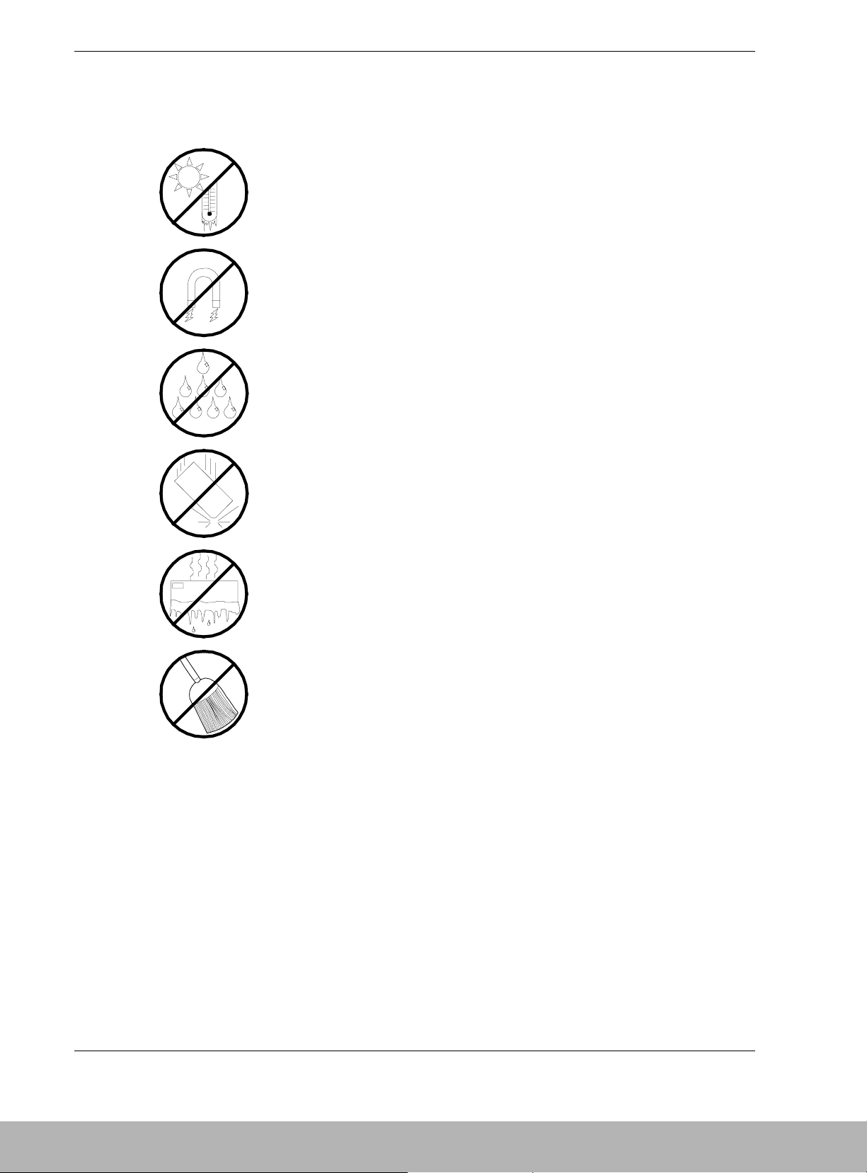
Care and Handling
Use the following guidelines to properly handle and care for your system.
Protect the system from extremely low or high temperatures. Let
the system warm (or cool) to room temperature before using it.
Keep the system away from magnetic forces.
Keep the system dry. Do not wash the system with a wet cloth or
pour fluid into it.
Protect the system from being bumped or dropped.
Check the system for condensation. If condensation exists, allow it
to evaporate before powering on the system.
Keep the system away from dust, sand, and dirt.
Page 14

1
Overview
! Overview
! High Capacity Cooling Fans
! Power Supplies
! Security
! DAU Functionality
! Features and Indicators
Page 15
1-2 Disk Array Unit Overview
Overview
The NEC S1300 Disk Array Unit (DAU) provides highly available, fault-tolerant
storage in a rack-mount subsystem. The DAU uses high-speed Fibre Channel
technology. See Figure 1-1.
The Fibre Channel is a scalable, high-performance interconnect standard that enables
fast transfer of data between workstations, shared storage, peripherals and host systems.
At up to speeds of 2 Gigabits per second this data transfer technology combines the
attributes of a data channel with the attributes of a network. Fibre Channel is capable of
supporting multiple protocols and a variety of topologies, making it the most versatile
data transfer technology available.
The DAU supports RAID levels 0, 1, 5, and 10. Even if one disk module fails, the disk
array unit continues to function normally without interruption (Except for RAID
level 0).
A faulty disk module can be replaced without system shutdown. The DAU includes an
automatic rebuild feature by which data is automatically restored when a faulty disk
module is replaced. When one disk module is defined as a spare drive, the data in the
faulty disk module is immediately restored to the spare drive (hot spare feature). Using
the auto recovery and hot spare feature increases overall system availability and
reliability.
The DAU also includes a battery-backed cache memory data storage feature to increase
reliability and high-speed data processing. In addition to the disk modules, the cooling
fan system, the power supply system, and dual array controllers all have system
redundancy capabilities. Therefore, even if one of the redundant system components
fails, the disk array unit continues normal operation.
The DAU cabinet holds up to a maximum of fifteen hard disk drives. A disk enclosure
unit (option) is available to enable expansion of the storage capacity of the DAU by
adding up to fifteen additional hard disk drives.
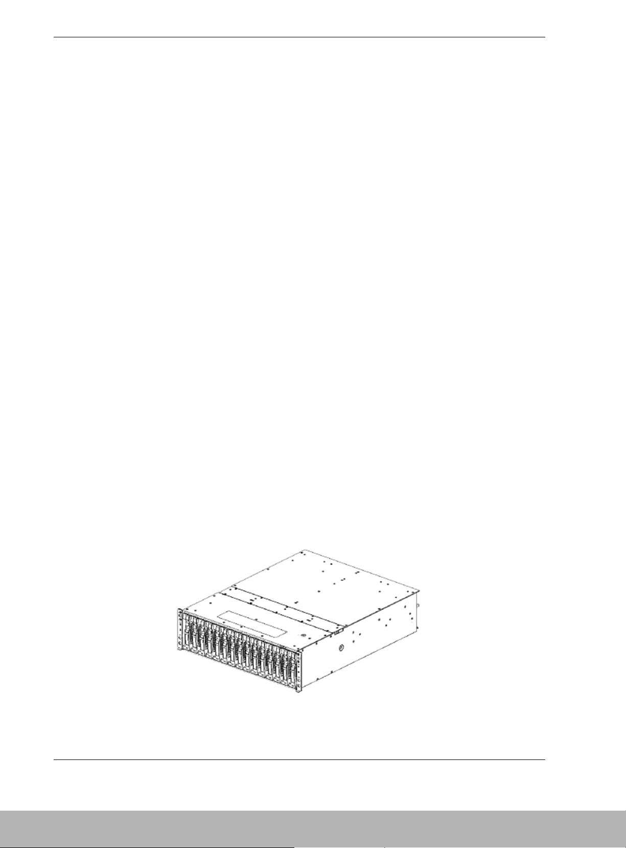
The DAU has a relatively small form factor of 3U and is available as a rack-mount
system that fits into a standard EIA 19-inch rack assembly.
Figure 1-1. Rack-Mount DAU Front View (Front Bezel not Shown)
Page 16

Disk Array Unit Overview 1-3
The DAU includes the following major features:
! 2.0 Gigabit per second data transfer rate .
! High bandwidth for demanding applications.
! The ability to share storage assets among many workstations.
! Easy cabling to host bus adapters.
! Hot-swap hard disk drive bays accessible from the front of the chassis. The drives
can be swapped in or out of the DAU without powering it down. The bays support
up to fifteen hard disk drives. Disk drives are high performance 10,000RPM and
15,000RPM hard disk drives connected to a high speed Fibre Channel-Arbitrated
Loop (FC-AL) disk drive interface. Drive capacities are 36GB, 73GB or 146GB.
! Hardware monitors (temperature, fans, and voltage) and software monitors to
indicate failures.
! LEDs to provide failure notifications.
! Support of RAID levels 0, 1, 5, and 10. If a fault occurs in a single disk module, the
DAU can continue the operation without loss of data (except RAID level 0).
! Battery-backed cache memory to ensure high-speed data processing.
The DAU system is designed for minimum downtime. Thus, the DAU contains the
following:
! A more reliable and flexible storage architecture that helps ensure continuous data
availability.
! Two power supplies for power system redundancy. With two power supplies, the
DAU will continue to operate with a single power supply failure. The self-contained
power supply units can be easily and safely hot-swapped from the rear of the chassis
without shutting down the DAU.
! Dual controllers, each containing cache memory. Cache memory data is protected by
battery backup units, to retain write data in the event of a system shutdown or power
failure.
! Fibre Channel disk drive bays accessible from the front of the chassis.
! Hot-swap Fibre Channel disk drive backplane, supporting fifteen drives. A failed
drive can be removed and a new drive installed without turning off system power.
Page 17
1-4 Disk Array Unit Overview
! Disk Drive Bays
The DAU supports 36GB, 72GB and 146GB hard disk drives. The chassis includes
fifteen Fibre Channel hot-swappable hard disk drive bays for mounting up to fifteen
hard disk drives in easily removable drive carriers. Each bay accommodates 1-inch hard
disk drives.
Note: The DAU contains a hot-swap backplane that requires a
40-pin single connector attachment connector on the drives that you
install.
The design of the drive mounting uses a carrier rail system making it possible to "hot
swap" a drive without shutting down the DAU.
High Capacity Cooling Fans
The DAU contains two power supplies, each of which contains two high capacity
cooling fans. The DAU will be adequately cooled even if one of the fans fails. Also,
should any of the fans fail, they may be replaced without powering down the DAU. The
fans draw air across the hard disk drives and electronics of the system and exhaust out
through the rear panel.
Power Supplies
The DAU contains two auto-sensing 480-watt power supplies at an operating frequency
of 50/60 Hz. With two power supplies installed, in the event of a power supply failure,
the load is transferred to the remaining power supply without interruption to normal
operation.
Note: The power supplies are not hot swappable unless there
are two supplies installed.
The power supplies are designed to comply with existing emission standards and
provide sufficient power for a fully loaded system configuration.
Security
A security lock on the front bezel of the DAU prevents unauthorized entry to the
storage drives. Rack-mounted DAUs are also secured in the system cabinet by locking
mechanisms installed on the system rack front and rear doors.
Page 18
Disk Array Unit Overview 1-5
DAU Functionality
Hot Spare Feature
Spare disks can be installed in a disk array configuration that includes several disks. If a
disk fails in a configuration that includes the spare disk, the data located in the defective
disk is recovered to the spare disk. After the data recovery, the disk array configuration
operates normally. The defective disk module can be replaced without turning off the
power of the disk array unit, provided the disk array unit is configured as RAID level 1,
5, or 10.
To use the hot-spare feature, an optional spare disk must be installed.
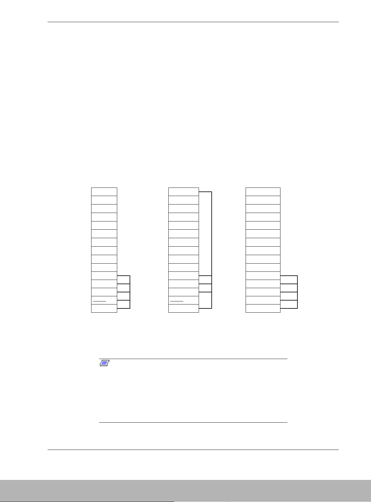
An example of the hot spare feature is shown in Table 1-1. In this example, hard disk
drives DRV0, 1, 2, 3, 4, and 14 are configured as a disk array. DRV14 is designated as
the spare disk. Disk DRV1 fails and its data is recovered in spare disk DRV14. When
recovery is complete, disk DRV1 is replaced without powering down the unit. Once
disk DRV1 is replaced, data is restored from spare disk DRV14 to the new disk DRV1.
Table 1-1. Hot Spare Feature Example
DRV14
Spare disk
DRV14 DRV14
Spare disk
DRV13 DRV13 DRV13
DRV12 DRV12 DRV12
DRV11 DRV11 DRV11
DRV10 DRV10 DRV10
DRV9 DRV9 DRV9
DRV8 → DRV8 → DRV8
DRV7 DRV7 DRV7
DRV6 DRV6 DRV6
DRV5 DRV5 DRV5
DRV4 DRV4 DRV4
DRV3 DRV3 DRV3
DRV2
LDN0 RAID5
DRV2
LDN0 RAID5
DRV2
LDN0 RAID5
DRV1 DRV1 DRV1
DRV0 DRV0 DRV0
Failure in DRV1 Recovery of data
in spare disk
Replacement of DRV 1
Restore the data from spare
disk to DRV 1
* DRV: Disk module
LDN: Logical Disk Number
Notes: The hot spare feature cannot be used with RAID
level 0. Use the hot spare feature with RAID levels 1, 5, or 10.
Do not move any factory-installed disk modules into another
slot.
The hot spare feature works only when a spare disk has the
same capacity and speed as the defective disk.
Page 19
1-6 Disk Array Unit Overview
Write Cache Feature
With RAID level 5, the performance of the DAU may be decreased somewhat when
writing small amounts of data to a disk. To increase performance, the DAU is equipped
with cache memory. When write data is stored in cache memory, the DAU may
terminate command processing and then write data to disks for improved performance.
However, if the power is disrupted before the data in cache memory is written to disk,
the data in the cache memory could be lost. To prevent this, the DAU power supplies
each include a battery backup unit to supply power to the cache memory, thereby
retaining data in the cache memory should the power fail. The battery backup unit is
fully charged after eight hours of operation.
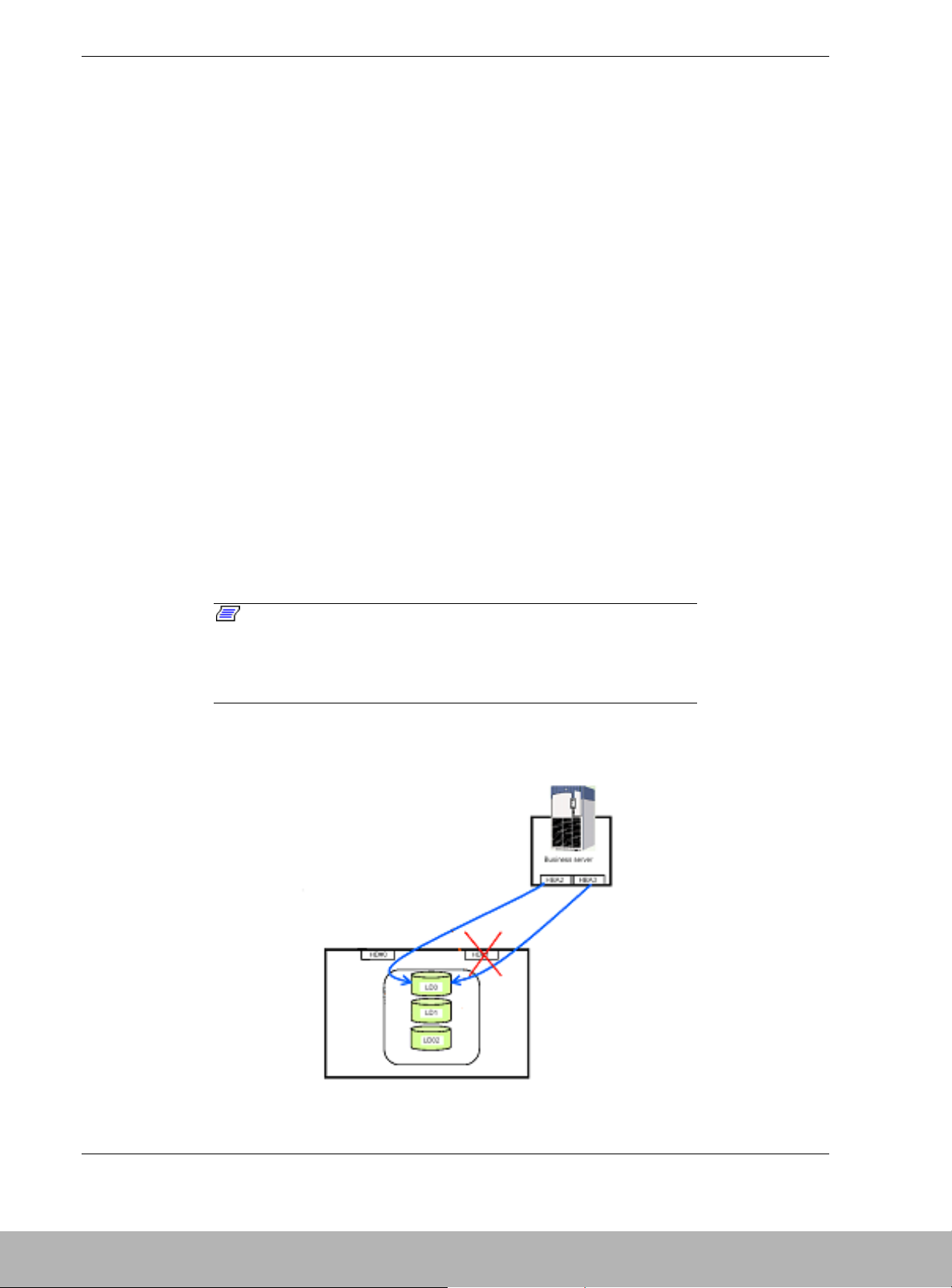
Cross Call Feature
By using the cross call feature, logical disk drives can be accessed from alternative
paths within the DAU, even if a controller fails. The cross call feature minimizes server
downtime thereby enhancing system performance. The cross call feature of the DAU
can be set with management software. The cross call feature has two states:
! Off state In this state, the DAU is accessible only from the host adapter (HBA) of
the bound host.
! On state (shipping default) In this state, all logical drive numbers (LDNs) in the
DAU are accessible from both controllers or one controller should one of the
controllers fail.
Note: Since one LDN is recognized from each controller, this
cross call must be used on the system where the logical disks can be
controlled exclusively. When you want to use the alternative path
switching feature of the host, the cross call feature must be turned
on.
Figure 1-2 illustrates a system connected to the DAU with the cross call feature turned
on and a failure with DAU controller HD#1.
Figure 1-2. Cross Call Feature Connections
Page 20
Disk Array Unit Overview 1-7
Notes: A controller is called as HD (Host Director) in the
management software.
A logical disk configuring the RAID is called as LD (Logical Disk), and
the internal number of LD is called LDN (Logical Disk Number) in the
management software.
Initial Assignment Feature
You can assign a logical disk to the controller on the path to which you bound the
logical disk (built the RAID).
When an attempt is made to access the logical disk from the unassigned controller, the
error "illegal request - not assigned" is returned. When an attempt is made to unbind
this logical disk from the unassigned controller, the same error is returned. However, if
the ownership has been changed, the initial assignment feature is transferred to the
unassigned controller.
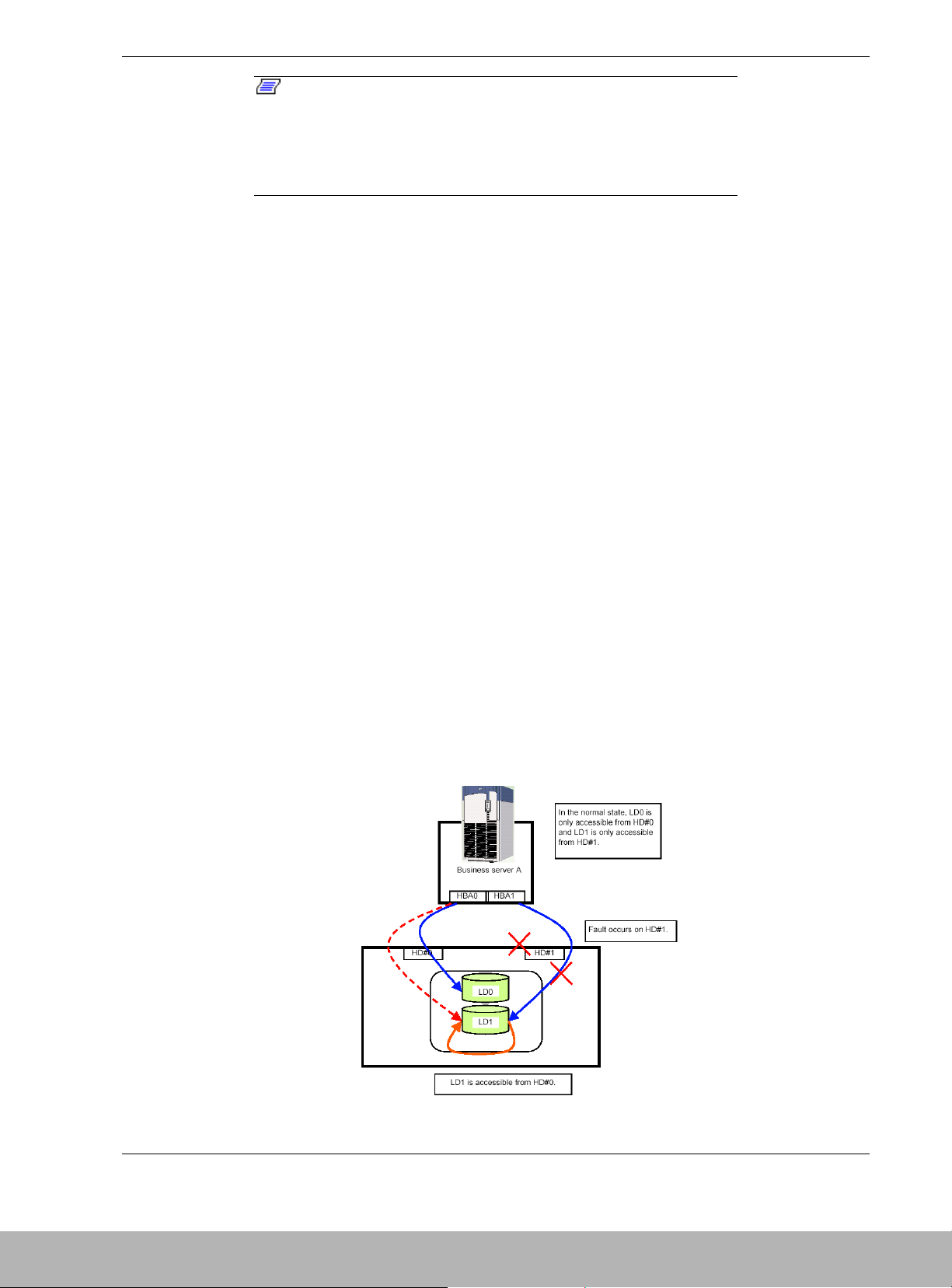
Auto Assignment Feature
The auto assignment feature allows you to access any logical disk in the subsystem
from the unassigned controller if the assigned controller is down. This feature is active
while the cross call is disabled.
When an I/O request to a logical disk not assigned to a DAU controller is received, the
system examines whether the adjacent controller is down. If the adjacent controller is
down, the system cancels assigning the logical disk to that controller and reestablishes
the assignment to the controller receiving the request. This reassignment is maintained
until the downed controller is operable, or a status change is received from management
software.
Even when the system in not equipped with the alternative auto assignment feature,
making the system recognize the logical disk again permits the access, allowing to
minimize the influence to the system operation. Figure 1-3 illustrates the Auto
assignment feature.
Figure 1-3. Auto Assignment Feature
Page 21

1-8 Disk Array Unit Overview
Expand LUN Feature
The Expand LUN feature increases the number of logical disks available from the host.
When running Windows NT or Windows 2000, the expand LUN feature is disabled
(shipping default). This setting can be changed with the NEC Storage Manager
(management software).
Note: When the DAU is connected to a host server that does not
support the Expand LUN feature, and this feature is turned on, the
host server may not recognize the DAU. If this occurs, the default
setting (Expand LUN feature off) may not be restored with the NEC
Storage Manager management software, resulting in system fault.
Auto Repair Mode
When the disk array includes an unused spare disk, you can select whether the repair
operation is started automatically or manually by using the NEC Storage Manager
management software. Auto repair mode is set to enable (shipping default).
Notes: If auto repair mode is disabled during a repair, the
current repair continues and is not terminated. The new setting will
take affect for the next repair.
When auto repair mode is enabled in the standby state, the repair is
not immediately initiated. The new setting will take affect for the next
repair.
When auto-repair mode is turned on and the physical disk status is
examined from the management software, "rebuilding" status is
displayed indicating the repair is in process. When auto-repair is
turned off and a disk fails, the status “reduce” is displayed until the
rebuild process is started manually.
Repair Time Feature
The default repair time is 10 hours. This time can be set from 0 (fastest) to 24 hours.
However, the repair might not be completed within the predetermined time depending
on the required repair. If a repair time is not specified, the fastest possible repair is
automatically executed.
With the repair time set to the shortest value (0), the RAID redundancy is rebuilt as fast
as possible to minimize exposure to a second failure. Setting the repair time to 24 hours
minimizes loss of performance during the repair.
Page 22

Disk Array Unit Overview 1-9
1BBU Cache Enable Mode
Normally your DAU includes two battery backup units to retain write data in the cache
memory of each controller in the event of a system shutdown or power failure. When
only one battery backup unit is in service, the DAU is not redundant and data loss may
occur if this battery unit fails. For this reason, it is recommended that 1BBU cache
enable mode be turned off when only one battery backup unit is in use.
OFF state: The write cache is disabled in the single-BBU condition.
ON state: The write cache is enabled even in the single-BBU condition. (Shipping default)
1CNT (Controller) Cache Enable Mode
Normally your DAU includes two controllers, each containing cache memory to retain
write data in the event of a system shutdown or power failure. When only one controller
is in service, the DAU is not redundant and lost data may occur if the cache in this
controller is enabled and this controller fails. For this reason, it is recommended that
1CNT cache enable mode be turned off when only one controller is in use.
OFF state: The write cache is disabled in the single-controller condition. (Shipping default)
ON state: The write cache is enabled even in the single-controller condition.
Access Control Features
Objective of Access Control
Access control allows logical disks in a DAU the ability to establish port and host
access permissions. Access control also provides a logical disk masking feature on a
port-by-port or host-by-host basis to protect the data and ensure the security.
About Access Control
To achieve the above objectives, the access control determines those logical disks
accessible from the controller or host and masks these disks. When you want to use the
access control, the cross call feature must be turned on.
Modes Supported by Access Control
The access control feature supports the following two modes.
! Port mode
! WWN mode
Page 23
1-10 Disk Array Unit Overview
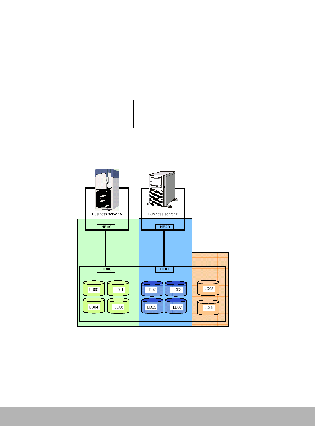
Port Mode
Port Mode establishes and maintains the logical disks accessible from each port
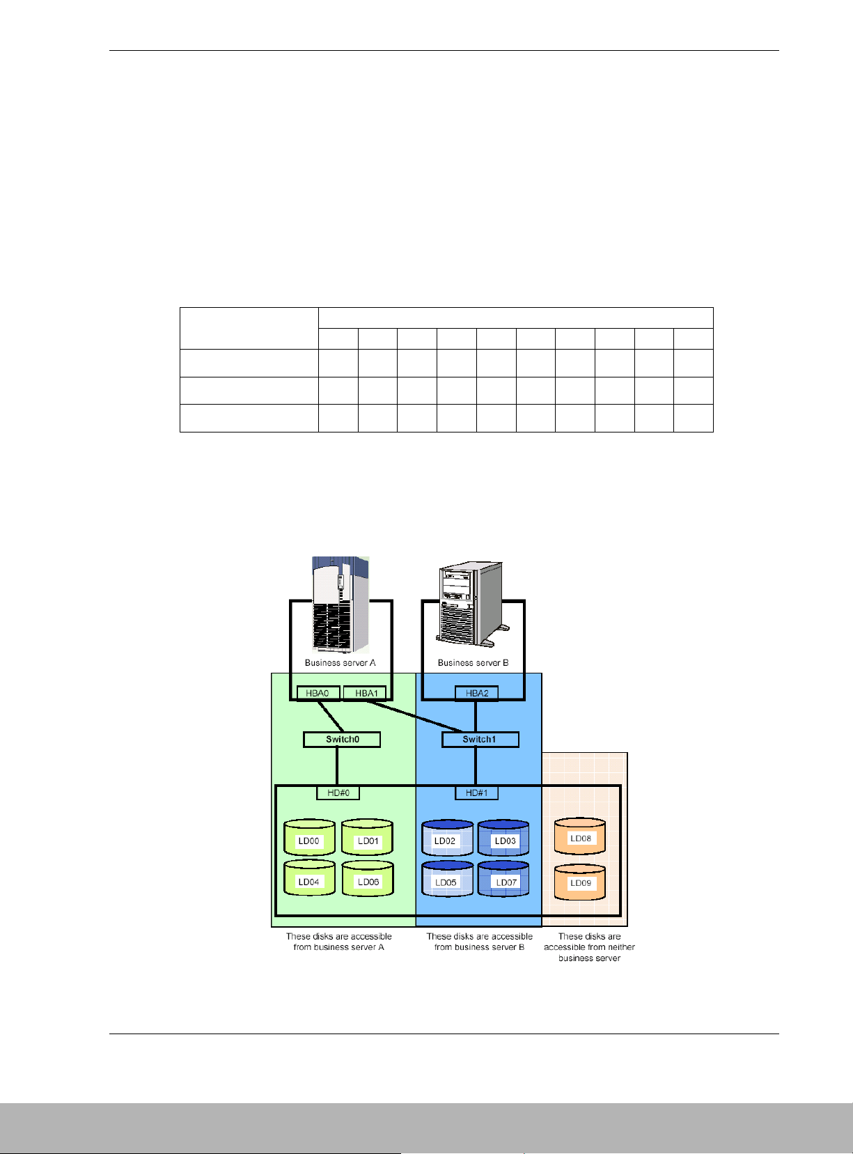
(controller) in the DAU. Table 1-2 shows logical disks assigned to each port in a DAU.
Figure 1-4 shows two business servers and the logical disks (LDs) assigned to each
using port mode. Business server A can access logical disks LD0, LD01, LD04, and
LD06 while business server B can access logical disks LD02, LD03, LD05, and LD07.
LD08 and LD09 are inaccessible from either business server.
Table 1-2. Setup of HD and LD Numbers
Logical Disk Number (LD)
Hard Disk (HD) Port
Number
00 01 02 03 04 05 06 07 08 09
0
√√
––
√
–
√
–––
1––
√√
–
√
–
√
––
Legends
√: Registers the HD number in the access limitation list as accessible number.
–: Registers the HD number in the access limitation list as inaccessible number.
Figure 1-4. Port Mode Logical Drives Assignments to Business Servers
Page 24
Disk Array Unit Overview 1-11
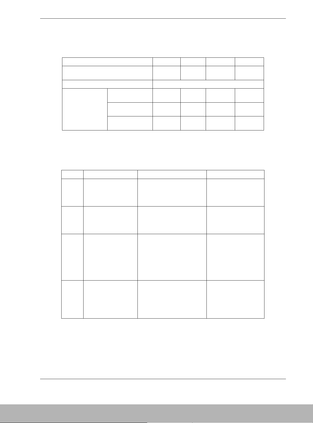
WWN (World Wide Node) Mode
WWN mode establishes and maintains the logical disks accessible from each WWN of
the host HBA in the DAU to control the access to the logical disks on a host-by-host
basis. Table 1-3 shows logical disks assigned to each HBA. Figure 1-5 shows two
business servers and the logical disks (LDs) assigned to each using WWN mode.
Business server A can access logical disks LD00, LD01, LD04, and LD06 while
business server B can access logical disks LD02, LD03, LD05, and LD07. LD08 and
LD09 are inaccessible from either business server. If business server A supports the
path switching feature, the logical disks of HD#0 are accessible through switch 1 even
when switch 0 is unavailable and access is rejected.
Table 1-3. Setup of WWN and LD Numbers
Logical Disk Number (LD)
Host Bus Adapter
(HBA) Number
00 01 02 03 04 05 06 07 08 09
0
√√
––
√
–
√
–––
1
∆∆
––
∆
–
∆
–––
2––
√√
–
√
–
√
––
Legends
√: Registers the HBA WWN and HD number in the access limitation list as accessible items.
–: Registers the HBA WWN and HD number in the access limitation list as inaccessible items.
∆: Registers the WWN of HBA0/HBA1 and the HD number in the access limitation list as accessible
items. If the business server A supports the path switching feature, the logical disks are accessible
through switch 1 even in case that switch 0 is faulty and the access is rejected.
Figure 1-5. WWN Mode Logical Drives Assignments to Business Servers
Page 25

1-12 Disk Array Unit Overview
Path Fail-over Feature
The DAU is equipped with two disk array controllers to enable dynamic cross call
control. The two disk array controllers can access to all logical disks. If either of the
disk array controllers fails, the DAU can continue the operation by using the remaining
disk array controller. In order to use this function, optional software may be required, as
well as the operating system.
Dynamic Capacity Expansion
The Dynamic Capacity Expansion feature can be used to add capacity to the RAID 5.
RAID 5 configurations of 3 to 14 drives can be expanded. Physical disks may be added
one at a time, and the expansion can be started only after the previous expansion has
completed. NEC Storage Management or MSMGR are used to initiate the expansion.
Management Software
NEC Storage Management software provided with your DAU, allows you to perform
the following functions from the host computer:
! Setting and resetting RAID configurations (RAID0, 1, 5, 10, and hot spare disk)
! Setting of various features
! Downloading firmware updates
! Collecting error logs.
Page 26
Disk Array Unit Overview 1-13
RAID Configurations
Available DAU RAID configurations are shown in Table 1-4.
Table 1-4. RAID Configurations
RAID Level RAID0 RAID1 RAID5 RAID10
Number of physical drives in configuration 1, 3, 5, 10,151+1 2+1 to 14+1 2+2 to 7+7
Number of logical drives per subsystem 1,024 max.
With 36-GB disks 35.7 to
536.1GB
35.7GB 71.4 to
500.3GB
71.4 to
250.1GB
With 73-GB disks 71.6 to
1074GB
71.6GB 143.2 to
1002GB
143.2 to
501.2GB
Storage capacity per
logical drive
With 146 GB disks 142.9 to
2144GB
142.9GB 285.8 to
2001GB
285.8 to
1000GB
* A combination of disk modules of the same capacity and same rotational speed are required for
configuring logical drives.
Characteristics of the RAID levels are shown in Table 1-5.
Table 1-5. RAID Level Characteristics
Level Function Advantage Disadvantage
RAID0 Striping Highest data read/write rate
Maximum storage capacity
Data recovery disabled
(Fault in a single disk
module causes data to be
lost.)
RAID1 Mirroring Data recovery enabled Low-speed data writing
All data is written to two
disk modules.
Minimum data recovery time The required disk capacity
is twice the used storage
capacity.
RAID5 Striping of data and
redundant data
Data recovery enabled Three or more disk
modules are required.
Larger capacity is available for
users because the capacity of
redundant data is smaller than
that of RAID1.
The required storage
capacity is one extra
physical disk per rank.
High-speed data write
RAID10 Use of both mirroring
and striping
Data recovery enabled Four or more disk modules
are required.
High-speed data read/write The required storage
capacity of disk module is
twice the used storage
capacity.
Page 27

1-14 Disk Array Unit Overview
Arbitrary Logical Disk Capacity
An arbitrary logical disk capacity can be bound by using the management software. To
bind logical disks, enter the capacity in MBs (M=1024^2).
For management software, the logical disk capacity can be specified with an integer
multiple of the basic capacity, or the least common multiple of (stripe size) × (number
of data disks) and 1024 (400h).
Ex: Capacity secured in RAID-5 (6+P)
Stripe size (100h) × number of data disks (6h) = 600h (768 KB)
The basic capacity is the least common multiple of 400h and 600h.
The capacity must be an integer multiple of C00h (1536 KB).
Maximum Logical Disk Capacity
The maximum capacity per logical disk is shown in the table below (including the
system capacity of 2 MB).
Enter the value resulting from subtracting the system capacity (2 MB) from the capacity
in Table 1-6 as the LD capacity.
Table 1-6. Maximum Logical Disk Capacity (MB) M=1024^2
RAID Type Number of PDs 36GB 73GB 1476GB
Single unit 34087 68284 136325
RAID0 (1) 1 34087 68284 136325
RAID0 (3) 3 102261 204852 408975
RAID0 (5) 5 170435 341420 681625
RAID0 (10) 10 340870 682840 1363251
RAID0 (15) 15 511305 1024260 2044876
RAID1 (1+1) 2 34087 68284 136325
RAID5 (2+P) 3 68174 136568 272650
RAID5 (3+P) 4 102261 204852 408975
RAID5 (4+P) 5 136348 273137 545300
RAID5 (5+P) 6 170435 341420 681625
RAID5 (6+P) 7 204522 409704 817950
RAID5 (7+P) 8 238609 477988 954275
RAID5 (8+P) 9 272697 546274 1090600
RAID5 (9+P) 10 306783 614556 1226926
RAID5 (10+P) 11 340870 682840 1363251
RAID5 (11+P) 12 374957 751124 1499576
RAID5 (12+P) 13 409044 819411 1635901
RAID5 (13+P) 14 443131 887692 1772226
RAID5 (14+P) 15 477218 955976 1908551
RAID10 (2+2) 4 68174 136568 272650
RAID10 (3+3) 6 102261 204852 408975
RAID10 (4+4) 8 136348 273137 545300
RAID10 (5+5) 10 170435 341420 681625
RAID10 (6+6) 12 204522 409704 817950
RAID10 (7+7) 14 238609 477988 954275
Note:The capacities in the table above include the system capacity (in T&D area) of 2 MB.
Page 28
Disk Array Unit Overview 1-15
Features and Indicators
The DAU contains several features and indicators located on the front and rear of its
chassis. The LED indicators assist in determining the current state of the DAU
subsystem. The following subsections describe the front and rear chassis features and
indicators of the DAU.
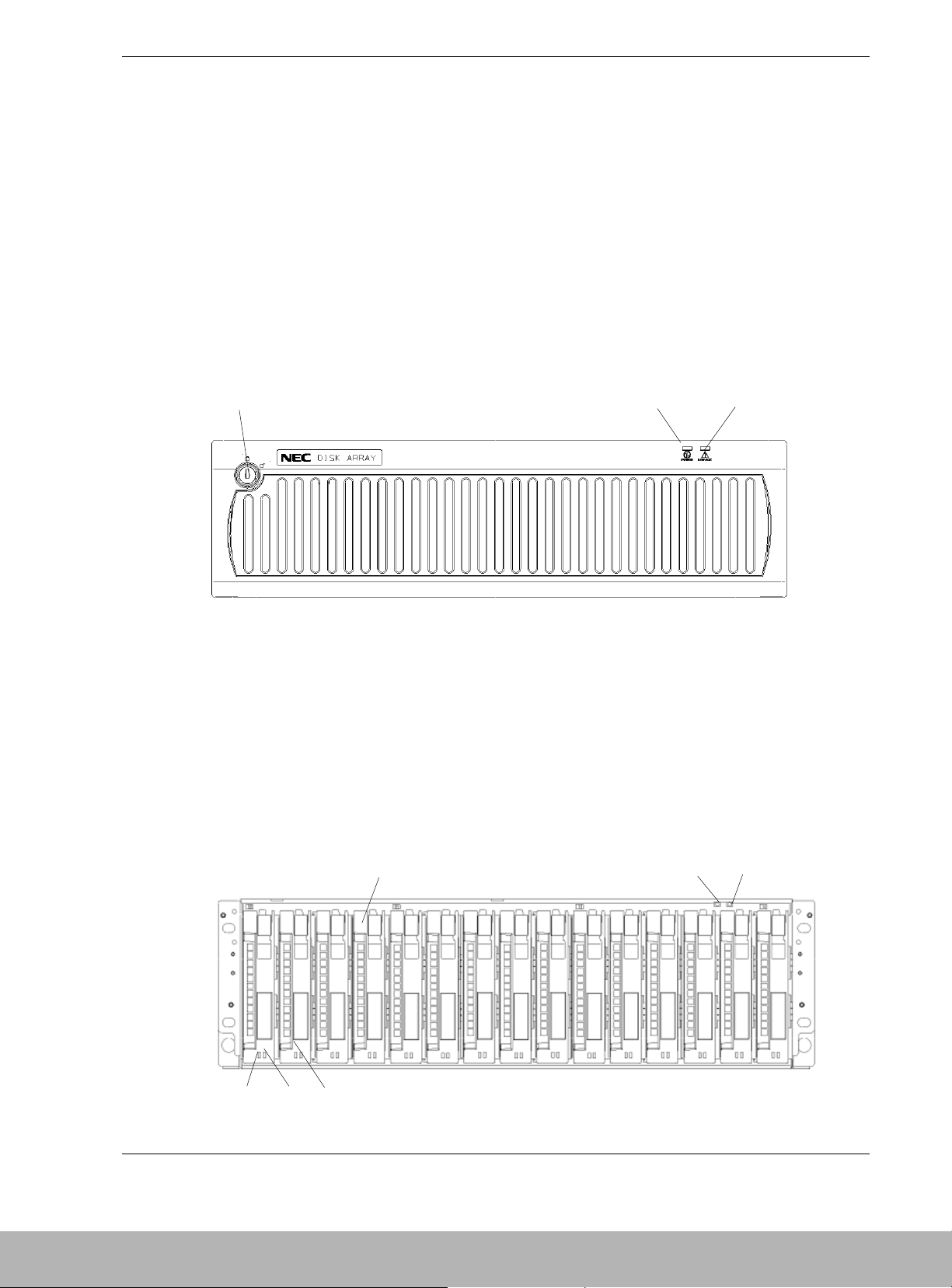
Front Panel
Figure 1-6 shows the front bezel and the indicators visible when the front bezel is
installed. The front bezel can be removed by releasing the lock with the accessory key.
Grasp the sides of the bezel and pull the bezel toward you. The power and service LEDs
are described in Figure 1-7.
A Security Lock
B Power LED (green)
C Service LED (Orange)
Figure 1-6. Front Chassis Features and Indicators (Bezel Installed)
Front Chassis Features and Indicators
Figure 1-7 shows the features and indicators located on the front of the DAU with the
front bezel removed. Disk modules are labeled 00 – 14 and are installed left to right.
00 01 02 03 04 05 06 07 08 09 10 11
12 13 14
A
B
C
C
A
B
D
E
F
Page 29

1-16 Disk Array Unit Overview
A Tray Ejector The ejector is used to secure and remove the disk module
or dummy tray to the chassis.
B POWER LED (green) The POWER LED lights green if the AC power is supplied
and the power switch is set to ON. The LED is off if the
power switch is set to OFF.
C SERVICE LED (orange) The SERVICE LED lights orange when the disk array unit
encounters an error. The LED flashes during the self-test
and initialization immediately after the power is turned on.
The LED goes off when the disk array unit has started, and
it is off while the disk array unit is operating normally.
D Disk module The dedicated tray containing the HDD (hard disk drive).
The disk modules are installed in three slots from the left
and bound as RAID level 5 (shipping default). The remaining
twelve slots contain dummy trays.
E HDD READY LED (green) The HDD READY LED lights green while the disk module
operates normally. The LED blinks when the disk module
transfers data.
The HDD READY LED blinks during the self-test or
initialization just after power-on.
F HDD FAUL T LED
(orange)
The HDD FAULT LED lights at the occurrence of an error in
the disk drive. The LED is off while the disk drive operates
normally.
Figure 1-7. Front Chassis Features and Indicators (Bezel Removed)
Page 30
Disk Array Unit Overview 1-17
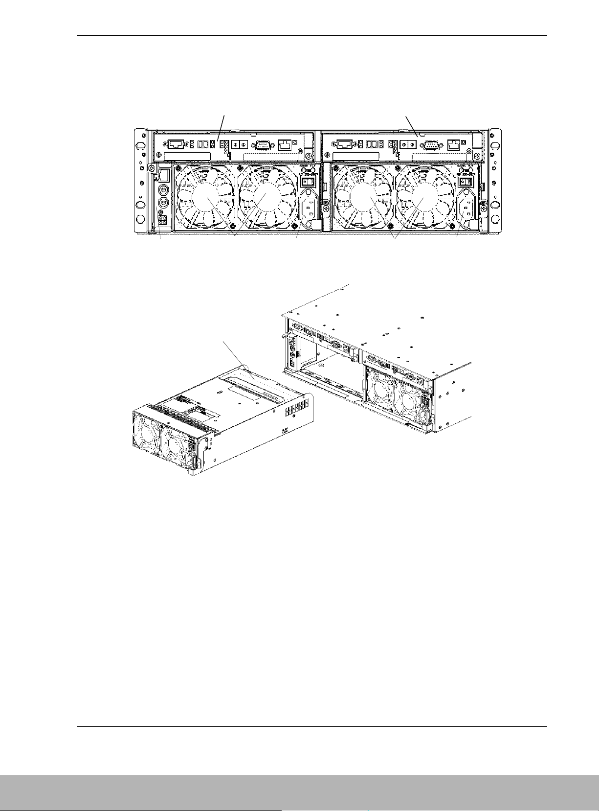
Rear Chassis Features
Figure 1-8 shows the features and indicators located on the rear of the DAU.
A Controller (CONT1)
B Controller (CONT0)
C Power Supply (PS0)
D Fans (FAN0)
E Power Supply (PS1)
F Fans (FAN1)
G Service Processor (SVP)
H Battery Backup Unit (PS1)
Figure 1-8. Rear Chassis Features
A
B
C
DE
F
G
H
Page 31

1-18 Disk Array Unit Overview
Power Supply
Figure 1-9 shows the features and indicators located on the rear of the power supply.
A Power Good LED (Green) The POWER GOOD LED lights green when the AC power is
supplied to the disk array unit and the power switch is set to
ON. The LED is off if the power switch is set to OFF or a
fault occurs in the power supply.
B Power Fault LED
(Orange)
The POWER FAULT LED lights if a fault occurs in the power
supply.
C Power Switch The power switch is used to turn the disk array unit power
on or off.
D Ejector The ejector is used to eject the power supply from the DAU
chassis.
E Power Plug The power plug supplies power to the disk array unit. Plug
in one end of the attached power cord to this plug and plug
the other end of the cord to the AC outlet of a voltage of
120VAC 50Hz or 60Hz. This disk array unit uses auto-sense
power supplies for 100V - 240VAC (50/60Hz) operation.
The power cord shipped with the DAU is for 100-120VAC. If
the disk array unit is used at a voltage other than 100120VAC, prepare the proper cord for the voltage and current
capacity for the unit.
F Stopper (power cord
retainer)
The stopper prevents the power cord from being removed
unexpectedly from the power supply.
Figure 1-9. Power Supply Features and Indicators
A
C
D
E
F
B
Page 32

Disk Array Unit Overview 1-19
DAU Controller
Figure 1-10 shows the features and indicators located on the rear of the DAU controller.
M
A L INKUP LED
(DE-LINK)
This LED lights green if the Disk Enclosure Fibre Channel (DE-FC)
connector (FC port) becomes operable (linked). This LED is off during
self-test or initialization, just after power-on.
B FC Connector Connection between fiber channel controller and the host (HOST-FC).
This connector is used to connect the disk array unit to the basic
processing unit (host).
C LINKUP LED
(HOST LINK)
This LED lights green while the FC interface with the host is operable.
D LINKUP LED
(DISK-LINK)
This LED lights green if the respective disk module becomes operable
(links up). This LED is off during the self-test or initialization, just after
power-on.
E AL-PA switch This switch sets the address of the disk array unit as a fiber channel
device in the fiber channel loop.
At shipment, the addresses of CONT0 and CONT1 are set to "00" and
"01," respectively. Set AL-PA so that the address may not be the same
as that of another fiber channel device in the same host FC loop.
F RS-232C
connector
The RS-232C connector is provided for maintenance of the disk array
unit.
G Ejector This device is used to install and remove the controller.
H DE-DIAG LED
(green)
The DE-DIAG LED lights green when the controller is ready for
diagnosis.
I DE-DIAG
connector
The DE-DIAG connector is provided to connect a cable to the Disk
Enclosure (DE) for diagnosing (monitoring) functions in the DE..
J1 FAULT LED
(orange)
The FAULT LED lights orange if a fault occurs in the controller.
A
C
D
EF
B
HG
I
J
K
4
2
1
3
M
N
L
Page 33

1-20 Disk Array Unit Overview
J2 BACKUP LED
(orange)
This LED, when lit, shows that the battery backup unit is charged and on
line to supply power to cache memory in the event of a power failure.
Replacing the controller, power supply, and/or battery backup unit while
the BACKUP LED is lit, loses the data in cache memory.
The battery backup unit supplies power to the cache memory for a
maximum of three days (72 hours in the full-charged condition). After
this time period, cache data may be lost.
J3 ACCESS LED
(green)
The ACCESS LED blinks while the controller is in operation.
J4 READY LED
(green)
The READY LED lights green while the controller operates normally.
The LED blinks during the self-test or initialization, just after power-on.
K L INKUP LED
(MATE-LINK)
This LED lights green if the other controller in the DAU becomes
operable (links up). This LED is off during the self-test or initialization,
just after power-on.
L HOST-2G LED The HOST-2G LED lights green while the FC interface with host is
operating at 2Gbps.
M DE 2G LED The DE 2G LED lights green while the FC interface with Disk Enclosure
is operating at 2Gbps.
N FC connector (for
connection with
disk enclosure)
(DE-FC)
This connector is used to connect the Disk Array unit to the Disk
Enclosure (DE).
Figure 1-10. Controller Features and Indicators
Page 34

Disk Array Unit Overview 1-21
Battery Backup Unit
Figure 1-11 shows the battery backup unit.
A Connector This connector is used to connect the battery backup unit with the power
supply.
Figure 1-11. Battery Backup Unit
A
Page 35

1-22 Disk Array Unit Overview
SVP Service Processor
Figure 1-12 shows the features and indicators located on the rear of the SVp service
processor.
A Ether
(10/100BASE-T)
connector
(Ethernet connector)
B UPS connector
(UPS0/UPS1
connector)
For the configuration in which the device receives AC power from UPS
(uninterruptible power supply), the signal cable connector is used to
connect the DAU with the UPS.
C CACHE FLUSH
switch
(pushbutton
switch)
This switch, when pushed, saves the cache data to the disk.
D FLT LED (FAULT
LED)
This LED, when lit, shows a fault occurred in the SVR.
When this LED flashes during the scheduled stop, the Write Back error
has occurred.
E CFL LED This LED, when lit, indicates that data is being saved from the cache to
the disk.
F RDY LED
(READY LED)
This LED, when lit, shows the service processor (SVR) is
operating in a normal state.
GLINK LED (TX/RX
LED)
This LED lights green when transmission/reception of data is being
transferred to and from a network.
Figure 1-12. SVP Service Processor
A
C
E
F
D
G
B
Page 36

Disk Array Unit Overview 1-23
Disk Enclosure Controller
Figure 1-13 shows the features and indicators located on the rear of the Disk Enclosure
controller.
ABC D E FGHI J K
RDY FLT
FC - OUT FC - IN
DIAG RDY
DIAG ID
PORT1
ENC ID
DE - DIAG
PORT0
A READY LED
(green)
The READY LED lights green while the controller operates normally.
The LED blinks during the self-test or initialization, just after power-on.
B FAULT LED
(orange)
The FAULT LED lights orange if a fault occurs in the controller.
CFC-OUT
LINKUP LED
(2
nd
DE LINK)
This LED lights green indicating the FC interface with a second DE is
operable. A second DE is not currently available with the S1300 DAU.
D FC connector (for
connection with a
2nd DE)
This connector is used to connect the Disk Enclosure (DE) with a
second DE. A second DE is not currently available with the S1300 DAU.
E FC connector (for
connection with
Disk Array Unit)
This connector is used to connect the Disk Enclosure (DE) with the Disk
Array Unit.
FFC-IN
LINKUP LED
(DAU LINK)
This LED lights green indicating the FC interface with the DAU is
operable.
G ENC ID Switch This switch sets the ID address of the DE Controller. This switch must
be set to 1 in the DE.
H DE-DIAG LED
(green)
The DE-DIAG LED lights green when the controller has a valid
diagnostic connection to the DAU.
I DIAG ID Switches The four DIP switches are set to OFF (down) for the first DE.
J DE-DIAG
connector
The DE-DIAG connector is provided to connect a cable to a second DE
for diagnosing (monitoring) functions in the second DE. A second DE is
not currently available with the S1300 DAU.
KDAU-DIAG
connector
The DAU-DIAG connector is provided to connect a cable to the DAU for
diagnosing (monitoring) functions in the DE.
Figure 1-13. Disk Enclosure Controller Features and Indicators
Page 37

Page 38

2
Setting Up The DAU
! Overview
! Selecting a Site
! Unpacking the DAU and Rack Mounting Hardware
! Rack-Mount Subsystem Assembly
! Connecting Disk Array Unit
! Connecting the Power Cords
! Connecting the DAU to Uninterruptible Power
Supplies
! Powering On/Off
! Scheduled Stop Procedure
Page 39

2-2 Setting Up The DAU
Overview
This chapter describes how to select a site, unpack the DAU and provides you
with assembly information for preparing and mounting the DAU into a system
rack. Also described are DAU to host cabling configurations, connecting the
power cord(s), powering On/Off the DAU, and configuring the Fibre Channel
address switches.
Selecting a Site
The DAU operates reliably in a typical office environment.
Choose a site that is:
! Near grounded, three-pronged power outlets.
Note: For the United States and Canada, this means a
NEMA 5-15R outlets for 100-120 VAC or NEMA 6-15R
outlets for 200-240 VAC. For other international sites, this
means three-pronged power outlets applicable for the
electrical code of the region.
!
WARNING
Be sure the power service connection is through a properly
grounded outlet.
!
CAUTION
Be sure that the power plug from each of the power supplies
is plugged into the same common ground power outlets.
! Clean, dust-free, and well ventilated. Front and rear ventilating openings
kept free of obstructions. Away from sources of heat, vibration or
physical shock.
! Isolated from strong electromagnetic fields and electrical noise produced
by electrical devices (such as air conditioners, large fans, large electric
motors, radio and TV transmitters, and high-frequency security devices)
! Spacious enough to provide at least five inches (13 centimeters) behind
the DAU and three inches (eight centimeters) on each side of the DAU
for proper cooling, airflow, and cable clearance.
Note: Provide an additional five inches (13 centimeters)
behind the DAU to facilitate changing the self-contained hotswap power supply unit.
Page 40

Setting Up The DAU 2-3
! Easily accessible for DAU maintenance and installation of DAU
upgrades.
Unpacking the DAU and Rack Mounting
Hardware
!
WARNING
The DAU weighs approximately 80 lbs (36 kg). If the DAU
contains numerous optional devices and rack mount parts, it
will weigh more. To avoid personal injury, make sure you
have someone help you lift or move the DAU.
Although the DAU and rack mount kit are inspected and carefully packaged at
the factory, damage may occur during shipping. Follow these steps for
unpacking.
1. Visually inspect the shipping containers; notify your carrier immediately of
any damage.
2. Place the DAU shipping container on a flat, clean, stable surface. Carefully
remove the DAU and set it aside. If the DAU is damaged, notify your server
representative. See Figure 2-1, A.
3. Carefully remove the parts in the Accessories Kit and verify the contents.
See Figure 2-1, B through I and Table 2-1. If parts are missing or the
hardware is damaged, notify your server representative.
4. Save the containers and packing materials for any future reshipment.
Page 41

2-4 Setting Up The DAU
Figure 2-1. DAU and Rack Mount Kit Parts
B
D
C
A
F
G
H
I
E
Page 42

Setting Up The DAU 2-5
Table 2-1. DAU and Rack Mount Parts
Reference Description Reference Description
A Disk Array Unit (DAU) F User's Guide (located on CDROM)
B Left Rail Support Hook G Power Cords (2)
C Left Rail H Countersunk Head Screws (4)
D Right Rail Support Hook I M5 Screws (4)
E Right Rail
Rack-Mount Subsystem Assembly
Before You Begin
Before you begin, please review the following cautions, warnings, and general
guidelines.
! Avoid excessive vibration and shock. Dropping an electronic component
can cause serious damage.
! Do not disconnect or remove parts other than those specified in the
procedure.
! Do not touch I/O connector pins.
! All screws are Phillips-head, unless otherwise specified.
Static Precautions
An electrostatic discharge (ESD) can damage disk drives, option boards, and
other components. You can provide some ESD protection by wearing an
antistatic wrist strap attached to chassis ground when handling DAU
components.
Electronic devices can be easily damaged by static electricity. To prevent
damage, keep them in their protective packaging when they are not installed in
the DAU.
Page 43

2-6 Setting Up The DAU
Installing the Rails
Note: In the following procedure the left rail is shown as
viewed from the front of the rack. Right rail installation
procedures also apply to installing the right rail.
1. Rail support hooks are marked (L) for the left hook and (R) for right hook.
With the left rail support hook (L) facing towards the inside of the cabinet,
hang the top tab of the rail support hook on the square hole of the rack front
rail to which the DAU will be mounted. Be sure the counter-sunk holes in
the rail support hook are centered within the square holes of the rack front
vertical rail. Also, the hook projections on the rail support hooks should be
facing upwards. See Figure 2-2.
Figure 2-2. Positioning the Left Rail Support Hook
Rail support hook (L)
Hook
projections are
facing upwards
Top tab
Page 44

Setting Up The DAU 2-7
2. While holding the left rail hook in position with your left hand, engage the
cutout at the front of the left rail into the rail support hooks protruding
through the cabinet vertical rail. The front of the left rail should be
positioned behind the cabinet front vertical rail and resting on the two left
rail hooks. See Figure 2-3.
Figure 2-3. Positioning the Left Rail
3. Secure the left rail to the rail support hook with two countersunk head
screws. See Figure 2-4.
Figure 2-4. Securing the Left Rail
Countersunk
head screws
Cutout of rail
Page 45

2-8 Setting Up The DAU
4. At the rear of the rack, slightly loosen the four countersunk head screws in
the side of the left rail. These screws must not be removed. See Figure 2-5.
Figure 2-5. Tightening the Countersunk Head Screws
5. Pull the inner rail toward you and engage the upper and lower rail tabs into
the rectangle holes. While holding the inner rail, screw the mounting bolts
(M5 bolts) into the threads of the inner rail. See Figure 2-6.
Figure 2-6. Securing the Inner Rail
Mounting bolt
Rail inner
Countersunk
head screws (4)
Page 46

Setting Up The DAU 2-9
6. Firmly tighten the four countersunk head screws loosened in Step 4.
See Figure 2-7.
Figure 2-7. Tightening the Countersunk Head Screws
7. Repeat steps 1 through 6 and install the right rail.
Installing the DAU into the System Rack
!
WARNING
To reduce the risk of personal injury or damage to the
equipment, a minimum of two people MUST lift the DAU into
the rack. The DAU weighs 80 lbs (36 kilograms). If the unit is
to be loaded above chest level, a third person must assist in
aligning the rails while the other two support the unit.
1. With one person grasping each side of the DAU, carefully align the DAU to
the rack’s slide rails and slide the DAU into the rack.
2. Secure the DAU to the system rack with two M5 screws. See Figure 2-8.
Countersunk
head screw
Page 47

2-10 Setting Up The DAU
Figure 2-8. Securing the DAU to the System rack
Connecting Disk Array Unit
The following sections provide information for connecting the DAU to the Host
server and the optional disk enclosure. Figure 2-9 show a typical DAU
installation and includes cabling for the optional disk enclosure.
Host Connection
1. Connect the disk array unit with the host using the two supplied
FibreChannel cables. Push the connector at either end of the cable into the
FC connector (HOST-FC) of the disk array controller (CONT0) until a click
is heard. The FC cable has the same connectors at both ends. Either
connector may be connected to the controller. See Figure 2-9.
2. Connect the other end of the FibreChannel cable to the connector of
FibreChannel controller installed in the host system. Connect the second
FibreChannel cable between the second disk array controller (CONT1) and
the host system.
Disk Enclosure Connection
1. Connect either end of the HSSDC-HSSDC cable into the DE-FC connector
(CONT0) on the disk array unit until a click is heard. The HSSDC-HSSDC
cable has the same connectors at both ends. Either connector may be
connected to the controller. Connect the other end of the HSSDC-HSSDC
cable into the FC-IN connector on adapter 0 (ADP0) of the disk enclosure
until a click is heard. See Figure 2-9.
2. Similarly, connect the second HSSDC-HSSDC cable into DE-FC connector
(CONT1) on the disk array unit until a click is heard. Connect the other end
of this HSSDC-HSSDC cable into the FC-IN connector on adapter 1
(ADP1) of the disk enclosure until a click is heard.
Page 48

Setting Up The DAU 2-11
3. Connect either end of the DE diagnosis cable into the DE-DIAG connector
of the controller (CONT0) until a click is heard. The DE diagnosis cable
also has the same connectors at both ends. Either connector may be
connected to the controller. Connect the other end of the DE diagnosis cable
into the PORT0 connector on adapter 0 (ADP0) of the disk enclosure until a
click is heard. See Figure 2-9.
4. Similarly connect either end of the second DE diagnosis cable into the DE-
DIAG connector of the controller (CONT1) until a click is heard. Connect
the other end of the DE diagnosis cable into the PORT1 connector on
adapter 1 (ADP1) of the disk enclosure until a click is heard.
Figure 2-9. Connecting the Disk Array Unit
Connecting the Ethernet Cable
To enable configuration changes and fault monitoring for the disk array unit by
the management software "NEC Storage Manager" through Ethernet, the LAN
cable must be connected.
Connect an Ethernet cable to the Ethernet connector (modular jack) on the LAN
card.
Connect the host system on which the management software "NEC Storage
Manager" is installed.
Contact your service provider to configure the LAN address.
HSSDC-HSSDC cables
DE diagnosis cables
FibreChannel cables
DAU
Disk
Enclosure
Host
Page 49

2-12 Setting Up The DAU
Connection Notes
Connection Cable
To connect the host bus adapter of the host system or the FC-AL switch with the
disk array unit, be sure to use the NEC-specified FC cable.
To connect the disk array unit with the additional disk enclosure, be sure to use
the DE cable provided with the additional disk enclosure, or the NEC-specified
DE cable.
Cable Length Limitations
FC optical cable for operating the host interface at 1Gbps: Up to [500 m]
FC optical cable for operating the host interface at 2Gbps: Up to [300 m]
Settings Topology and Data Transfer Rate
A topology and data transfer rate must be set correctly in accordance with the
host bus adapter to be connected or the connection mode of the FC-AL switch.
Factory-set topology and data transfer rate:
Topology: FC-AL Data transfer rate: 2Gbps
You can change the topology and data transfer rate of the FC connector for the
host bus adapter by changing the DIP switch settings on the controller. Refer to
Appendix A in this guide.
Setting DAU and Disk Enclosure Switches
Note: The controller IDs of disk array unit (CONT0 or
CONT1) must correspond to that of and that of disk
enclosure (CONT0 or CONT1).
The AL-PA switch sets the address of the disk array unit as a fiber channel
device in the fiber channel loop. At shipment, the addresses of DAU controllers
CONT0 and CONT1 are set to "00" and "01," respectively. Set the AL-PA so
that the address is not the same as that of another fiber channel device in the
same host FC loop. See Figure 1-10, E for the location of the controller AL-PA
switch. Refer to Appendix A for additional AL-PA switch settings.
The Enclosure ID (ENC ID) switch on each adapter of the additional disk
enclosure are factory-set to "1". See Figure 1-13, H. Make sure both ENC ID
switches are set to "1".
The DIAG ID switches on both adapters of the additional disk enclosure are
factory-set to "0". Make sure that both DE-DIAG ID switches are set to "0". See
Figure 1-13, J.
DE-DIAG ID = "0"
4 3 2 1ON
Page 50

Setting Up The DAU 2-13
Connecting the Power Cords
The DAU contains two 450-watt power supplies. The power supplies are
designed for automatic sensing of 115 or 230 VAC power, eliminating the need
for a line voltage selector switch. The power supplies operate at a frequency of
50/60 Hz. With two power supplies installed, if one fails, the second power
supply will ensure the DAU continues to operate without interruption.
Connect each power cord as follows.
1. Check that the power switch on the disk array unit and those on the host
system, host bus adapter, and FC-AL switch are all set to OFF.
See Figure 2-10.
OFF ON
Figure 2-10. Power Supply Switch
2. Insert the power cord into the power plug on the power supply, and secure
the power cord with stopper. See Figure 2-11. Repeat this step on the second
power supply.
Figure 2-11. Connecting the Power Cord to the Power Supply
3. Plug the male end of the power cords into NEMA 5-15R outlet for 100-120
VAC or NEMA 6-15R outlet for 200-240 VAC.
Page 51

2-14 Setting Up The DAU
If the power cords supplied with the DAU are not compatible with the AC
outlet in the region, obtain a suitable power cord that meets the following
criteria.
! The power cord must be rated for the available AC voltage and have a
current rating that is at least 125% of the current rating of the DAU.
! The power cord connector that plugs into the wall outlet must be
terminated in a grounding-type male plug designed for use in the region.
It must have certification marks showing certification by an agency
acceptable in the region.
! The power cord connector that plugs into the DAU must be an IEC- type
CEE-22 female connector.
! The power cord must be less than 1.8 meters (6.0 feet) long.
!
WARNING
The DAU shipped with a power cord for each power supply.
Do not attempt to modify or use the supplied AC power cord
if it is not the exact type required.
Page 52

Setting Up The DAU 2-15
Connecting the DAU to Uninterruptible Power
Supplies
Figure 2-12 shows the connection of a DAU to uninterruptible power supplies
(UPS). When the DAU is connected to a UPS, the system continues to operate
in the event of an unexpected power failure or momentary AC power
fluctuation.
Disk Array Unit
OUTPUT 1
OUTPUT 2
AC POWER
Straight cable
AC POWER
OUTPUT 1
OUTPUT 2
Figure 2-12. Connection the DAU to a UPS
To power
board
To power
board
Page 53

2-16 Setting Up The DAU
Cable Dressing
All the interface and power cables connected to the rear of the DAU should be
dressed and tie wrapped. Use special care not to kink or sharply bend the Fibre
Channel cables as they are easily damaged.
Route the cables so that they do not contact the door and guide rails on both
sides of the system rack. Also, ensure that there is some slack on all the cables
and especially the power cord to prevent it from being disconnected from the
DAU when the unit is pulled forward in the rack.
Powering On/Off
This section describes the sequence of steps for powering the disk array unit on
or off.
!
CAUTION
Carelessly turning power on or off may cause some data to
be lost, some software to operate incorrectly, or cause
damage to the unit.
Turning On AC Power
Note: Before turning on the AC power, check for loose
disk modules by ensuring each module is fully seated into
the disk bay.
1. Turn on the disk enclosure connected with the disk array controller (if
applicable), before turning on the disk array unit.
2. Turn on the power switches located on the rear panel of each power supply.
3. Confirm that the POWER LED (green) on the front panel of the DAU is on.
See Figure 1-7. Also check that the POWER LED located on each power
supply on. See Figure 1-9.
4. The disk array unit performs a self-test and initialization immediately after
the power is turned on. When the self-test and initialization complete and
the disk array unit become ready, the READY LEDs (green) on the
controllers in the disk array unit stop flashing and enter the on-state.
Confirm that the controller READY LEDs are on. See Figure 1-10, J4 for
the location of the controller LEDs.
Note: The disk array unit may take as long as four
minutes (at maximum) to start.
• Power on the host system.
Page 54

Setting Up The DAU 2-17
Turning Off AC power
1. Power off the host system.
The host writes cache data to the disk array unit.
2. Confirm that the cache data from the host is successfully written into the
disk array unit. To do this, check the DISK ACCESS LEDs located on the
rear panel of each controller. If the DISK ACCESS LEDs are flashing, data
remains in cache memory of disk array unit. Writing cache data onto disk
could take as long as 5 minutes. See Figure 1-10, J3 for the location of the
DISK ACCESS LED.
3. Turn off the AC power to the DAU. A power switch is located on the rear
panel of each power supply. See Figure 1-9.
!
CAUTION
When the DAU power is turned off before the cache data is
written to disk, the BACKUP LED on the controller is lit and
the disk array unit enters the backup mode. If the backup
mode lasts for more than three days (in the full-charged
condition), the cache data may be lost. Therefore, if the
BACKUP LED is lit, immediately turn on the disk array unit.
Since the data write is an automatic process, check the data
is completely written to the disk and then turn off the power.
4. Turn off AC power to the disk enclosure (if installed).
!
CAUTION
Turn off the power of host system, disk array unit, and disk
enclosure in that order. Turning off the power of disk
enclosure first may lose the data.
Page 55

2-18 Setting Up The DAU
Scheduled Stop Procedure
Perform the following procedure to be absolutely sure that cache data has been
completely written to disk before you power off the DAU.
1. Power off the host system.
The host writes cache data to the disk array unit.
2. Press and hold the CACHE FLUSH pushbutton (scheduled stop switch)
located on the SVP Service Processor until the CFL LED flashes or is
continuously lit (for at least two seconds). See Figure 1-12 for the location
of the CACHE FLUSH pushbutton and the CFL LED.
3. Release the CACHE FLUSH pushbutton when the CFL LED starts to flash
or is continuously lit. The CFL LED continually flashes as data is being
transferred from the cache to the disk.
4. Before turning off the disk array unit, make sure that the CFL LED is
continuously lit. Once the CFL LED is continually lit, the cache flush
operation has completed.
5. Power off the DAU.
Page 56

3
Adding and Removing
Components
! General Information
! Static Precautions
! Preparing Your DAU for Upgrade
! Accessing the DAU
! Hard Disk Drives
! Replacing a Controller Module
! Replacing a SVP Service Processor
! Replacing the Power Supply
! Replacing the Battery Backup Unit
Page 57

3-2 Adding and Removing Components
General Information
Note: Disk Array Unit (DAU) removal and replacement
procedures documented in this chapter also apply to the
Disk Enclosure (DE).
!
WARNING
Before doing the procedures in this manual, make sure that
your DAU is powered off and unplug the AC power cords
from the back of the chassis. Failure to disconnect power
before opening your DAU can result in personal injury and
equipment damage.
!
CAUTION
Operating your DAU with the cover removed can damage
your DAU components. For proper cooling and airflow,
always replace all covers before powering on your DAU.
!
WARNING
The SVP Service Processor contains a lithium battery. Do
not remove the lithium battery. Contact your sales agent.
The lithium battery may explode when it is brought close to
heat or fire or immersed in water. Dispose of lithium
batteries as required by local ordinance or as normal waste
if no local ordinance exists. Keep all batteries away from
children.
Static Precautions
An electrostatic discharge (ESD) can damage disk drives, the DAU board, and
other components. You can provide ESD protection by wearing an antistatic
wrist strap attached to chassis ground when handling DAU components.
Electronic devices can be easily damaged by static electricity. To prevent
damage, keep them in their protective packaging when they are not installed in
your DAU.
Page 58

Adding and Removing Components 3-3
Preparing Your DAU for Upgrade
Depending on the upgrade, you may need one or more of the following tools:
! Phillips screwdriver
! Small needle nose pliers
! Pen or pencil
! ESD workstation or antistatic wrist strap (recommended)
The following components may be added or removed from the DAU without
removing the DAU from the system rack.
! Hard disk drives
! Power supplies
! Controller Units and cache memory
! SVP Service Processor
! Battery Backup Units
Accessing the DAU
!
WARNING
To reduce the risk of personal injury or damage to the
equipment, a minimum of two people MUST lift the DAU out
of the rack. The DAU weighs 80 pounds (36.4 kilograms).
!
CAUTION
To make the DAU lighter and more manageable and to
protect your hard disk drives from damage, consider
removing the hard disk drives in the DAU before removing
the DAU from the rack.
To access the DAU in the system rack:
1. Open the front and rear doors to the system rack.
2. Terminate all applications and power down the Host and DAU following
procedures described in Chapter 2 of this guide.
3. Unlock the front bezel using the security key and remove the bezel.
The front bezel can be removed by releasing the lock with the accessory key.
Grasp the sides of the bezel and pull the bezel toward you.
Page 59

3-4 Adding and Removing Components
To secure the DAU into the system rack:
1. Install and lock the front bezel.
2. Close the front and rear doors of the system rack.
Hard Disk Drives
Your DAU supports two types of Fibre Channel hard disk drive modules. The
Fibre Channel drives must use the industry standard 40-pin Single Connector
Attachment (SCA) connector. The drives used in the DAU are one of these two
types:
! 36GB disk modules (10,000RPM) and (15,000RPM)
! 73GB disk modules (10,000RPM)
! 146GB disk modules (10,000RPM)
Installing or Swapping a Hard Disk Drive Modules in a Hot-swap
Bay
This procedure describes installing a new drive or swapping out a faulty drive
from one of the fifteen disk drive bays. The Fibre Channel drives use the
industry standard 40-pin Single Connector Attachment (SCA) connector. Your
DAU shipped from the factory with dummy drive carriers installed in all empty
drive bay positions. These dummy drive carriers have gray ejector buttons.
Drive carriers that have a disk drive installed in them have blue ejector buttons.
Note: To order a disk with a carrier, contact your sales
representative or dealer.
! If installing new drives, follow an installation scheme starting with the
left-hand drive. Fill the bays left to right. It is recommended that hot
spare disk drives be installed in the right-most positions.
! Hard disk drives may be removed or installed without powering down the
DAU.
! If an individual Fibre Channel drive fault LED (amber light) is on
steadily, this indicates that the drive has been flagged as faulty. Follow
the procedure described in this section to remove the faulty drive and
swap in a good one.
Note: ESD can damage disk drives, boards, and other
parts. This DAU can withstand normal levels of
environmental ESD while you are hot-swapping Fibre
Channel hard drives. However, we recommend that you do
all procedures in this chapter only at an ESD workstation or
provide some ESD protection by wearing an antistatic wrist
strap attached to chassis groundany unpainted m etal
surfaceon your DAU when handling parts.
Page 60

Adding and Removing Components 3-5
!
CAUTION
Drive manufacturers caution against moving a disk drive
that is still spinning because of possible damage to the drive.
After you determine which drive has been flagged as faulty, the procedure is the
same to swap a drive or to install one for the first time.
Installing or Swapping a Hard Disk Drive
1. Access the DAU by following procedures previously described in
“Accessing the DAU” found earlier in this chapter.
2. If installing a new hard disk drive module for the first time, perform the
following procedure; if swapping out an existing drive, go the Step 4.
3. Remove the dummy drive carrier from the Fibre Channel hard disk drive
bay in which you are installing the new disk drive. See Figure 3-1. Pull the
ejector on the dummy carrier assembly toward you to release the lock. A
click is heard when the lock is released. Once the lock is released, hold the
handle and pull the dummy carrier assembly out of the drive bay. Go to
step 5.
Figure 3-1. Removing a Dummy Hard Disk Drive Dummy Tray
Note: The dummy carriers are provided to maintain
proper cooling. Leave the dummy carriers in unused slots.
(Keep all removed dummy carriers for future use.)
4. If swapping a hard disk drive, remove its carrier from the Fibre Channel
hard disk drive bay by performing the following procedures:
Page 61

3-6 Adding and Removing Components
!
CAUTION
Depending on the drive fault, the drive may be still spinning
when you remove it. Follow the next steps exactly when
removing drives.
! Pull the blue ejector on the carrier assembly toward you to release the
lock. A click is heard when the lock is released. Once the lock is released,
hold the handle and pull the carrier out of the bay far enough to disengage
the drive connector from the backplane. Wait 30 seconds until the drive
spins down.
! Remove the drive carrier from the drive bay.
5. Remove the replacement drive carrier from its protective wrapper, and place
it on an antistatic surface. The hard disk drive has been already installed into
the carrier at the factory.
!
CAUTION
Observe static precautions. Use an antistatic wrist strap.
6. Affix a drive number label to the front of the hard disk drive. See Figure 1-7.
7. Record the drive model and serial numbers in the equipment log.
8. Install the drive carrier with drive into the drive bay as follows:
! With the ejector of the disk module opened, engage the guides on the top
and bottom faces of the disk module with the guide grooves on the disk
enclosure and insert the disk module into the drive bay. See Figure 3-2.
Figure 3-2. Installing the Drive Module into the Drive Bay
! Push the drive carrier into the drive bay until it docks with the Fibre
Channel backplane connector. Push on the carrier until the drive is
completely seated into the Fibre Channel backplane connector.
Page 62

Adding and Removing Components 3-7
! Push downward on the ejector button to lock the drive in place. See
Figure 3-3.
Figure 3-3. Locking the Ejector Button
9. Install and lock the front bezel.
10. Close the front door on the system rack.
Replacing a Controller Module
If a controller is defective, the SERVICE LED on the disk array unit front panel
lights orange (see Figure 1-7). In addition, the FAULT LED on the controller
lights orange (see Figure 1-10, J1). The defective controller may be replaced
with the power of the disk array unit remaining ON.
Replacement Procedure
1. Identify the defective controller module. The FAULT LED on the controller
rear panel lights orange.
2. Disconnect the host and disk enclosure (if applicable) cables connected to
the controller.
3. Loosen a screw securing the ejector of the controller module to the chassis.
See Figure 3-4.
Figure 3-4. Loosening the Controller Ejector Screw.
Page 63

3-8 Adding and Removing Components
4. Put your finger within the protrusion (shown in the figure) of the ejector, and
pull it the ejector toward you to release the controller module.
See Figure 3-5
Figure 3-5. Grasping the Controller Module Ejection Lever.
5. Open the ejector by pulling it towards the left. See Figure 3-6.
Figure 3-6. Removing the Defective Controller module.
6. Pull the controller out of the chassis, turn it over and set it on a clean
surface.
7. Remove the cache memory stick(s) from the controller. The cache memory
will be used in the replacement controller. See Figure 3-7.
Page 64

Adding and Removing Components 3-9
Figure 3-7. Controller Cache Memory Location
!
WARNING
The controller module may be hot. Handle carefully.
8. Set the DIP switch and AL-PA switch on the new controller module to the
same settings as the controller you removed. See the section “Setting the
AL-PA Switch” in Chapter 2 of this guide.
9. Install the cache memory sticks removed in Step 8 into the replacement
controller. See Figure 3-7.
10. Open the ejectors of the controller, insert the controller into the chassis. See
Figure 3-8.
Figure 3-8. Installing a Replacement Controller.
11. Insert the controller as far as it will go into the chassis, and close the ejector.
See Figure 3-9.
Page 65

3-10 Adding and Removing Components
Figure 3-9. Closing the Ejector.
12. Push in on the ejector until the controller is firmly seated in the chassis.
See Figure 3-10. Secure the ejector with the screw previously removed.
See Figure 3-4.
Figure 3-10. Securing the Ejector.
13. Connect the host and disk enclosure (if applicable) cables to the controller.
Page 66

Adding and Removing Components 3-11
Replacing a SVP Service Processor
!
WARNING
The SVP Service Processor contains a lithium battery. Do
not remove the lithium battery. Contact your sales agent.
The lithium battery may explode when it is brought close to
heat or fire or immersed in water. Dispose of lithium
batteries as required by local ordinance or as normal waste
if no local ordinance exists. Keep all batteries away from
children.
If a SVP service processor is defective, the SERVICE LED on the disk array
unit front panel lights orange (see Figure 1-7). In addition, the FAULT LED on
the SVP service processor lights orange (see Figure 1-12, D). The defective SVP
service processor may be replaced with the power of the disk array unit
remaining ON.
Replacement Procedure
1. Disconnect the cables connected to the SVP service processor.
2. Loosen a screw securing the SVP service processor to the chassis. See
Figure 3-11.
Figure 3-11. Loosening the SVP Service Processor Ejector Screw.
3. Grasp the points shown in Figure 3-12 and pull the SVP Service Processor
toward you. Remove the SVP Service Processor.
Page 67

3-12 Adding and Removing Components
Figure 3-12. Grasping the SVP Service Processor.
4. Install the replacement SVP Service Processor. See Figure 3-13.
Figure 3-13. Installing the Replacement SVP Service Processor.
5. When the SVP is in position where the finger on the right side of the SVP
service processor is as shown in Figure 3-14, push the projections at the top
and bottom of the SVP Service Processor until it is firmly seated in the
chassis.
Page 68

Adding and Removing Components 3-13
Figure 3-14. Completing the Installation of the SVP Service Processor
6. Secure the SVP service processor with the screw previously removed.
See Figure 3-15.
Figure 3-15. Securing the SVP Service Processor.
7. Connect the cables to the SVP Service Processor.
Finger
Page 69

3-14 Adding and Removing Components
Replacing the Power Supply
If a power supply is defective, the SERVICE LED on the disk array unit front
panel lights orange (see Figure 1-7). In addition, the POWER FAULT LED on
the power supply lights orange (see Figure 1-9, B). The defective power supply
may be replaced with the power of the disk array unit remaining ON.
Note: Complete the power supply replacement
within five minutes. If the time exceeds five minutes, the
protective feature of the disk array unit triggers the
shutdown sequence.
Replacement Procedure
1. Identify the faulty power supply with the "POWER FAULT" LED lit.
2. Turn off the power switch of the faulty power supply. See Figure 3-16.
OFF ON
Figure 3-16. Powering off the Power Supply
3. Unlatch the power cord retainer clip as shown in Figure 3-17 to release and
unplug the power cord.
Figure 3-17. Removing the Power Cord
Page 70

Adding and Removing Components 3-15
4. Loosen the ejector set screw of the faulty power supply. See Figure 3-18.
Figure 3-18. Loosening the Power Supply Ejector Set Screw
5. Put your finger on the protrusion of the ejector, and pull the ejector towards
you. See Figure 3-19.
Figure 3-19. Releasing the Power Supply Ejector.
6. Once the ejector is released, remove the power supply. See Figure 3-20.
Figure 3-20 Removing the Power Supply.
Page 71

3-16 Adding and Removing Components
7. Remove the crest fastener securing the battery press fitting to the power
supply. Then remove the battery press fitting. See Figure 3-21.
Figure 3-21. Removing the Battery Press Fitting
8. Disconnect the battery backup cable from the power supply and remove the
battery backup unit. See Figure 3-22.
Figure 3-22. Removing the Battery Backup Unit
9. Connect the battery backup unit cable to the replacement power supply.
Place the battery backup unit into the supply so that the battery label faces
upwards. See Figure 3-23.
Battery press fitting
Crest fastener
Connector
Page 72

Adding and Removing Components 3-17
Figure 3-23. Installing the Battery Backup Unit into the Replacement Power Supply
10. Install the battery press fitting, previously removed, into the replacement
power supply. Insert the rear tabs of the battery press fitting into the slots
behind the battery backup unit. Insert the front tabs of the battery press
fitting into slots on the battery backup unit. See Figure 3-24.
Figure 3-24. Installing the Battery Press Fitting.
Stopper
Connecto
r
BBU inserting edge
Notch
Battery press fitting
Page 73

3-18 Adding and Removing Components
11. Secure the crest fastener to the power supply. See Figure 3-25.
Figure 3-25. Securing the Crest Fastener.
12. Ensure the power switch of the replacement power supply is in off position
and the power cord is not plugged in the power connector.
13. Ensure the power supply ejector is in the open position and insert the
replacement power supply into the slot until it is firmly seated in the chassis.
See Figure 3-26.
Figure 3-26. Installing the Replacement Power Supply.
Crest fastener
Page 74

Adding and Removing Components 3-19
14. Push in on the ejector until the power supply is firmly seated in the chassis.
See Figure 3-27.
Figure 3-27. Closing the Power Supply Ejector.
15. Secure the ejector with the set screw. See Figure 3-28.
Figure 3-28. Securing the Power Supply Ejector.
16. Plug the power cord in the connector on the power supply, and secure the
power cord with the power cord retainer clip. Turn on the power switch.
Page 75

3-20 Adding and Removing Components
Replacing the Battery Backup Unit
If a battery backup unit is defective, the SERVICE LED on the disk array unit
front panel lights orange (see Figure 1-7). In addition, the POWER FAULT
LED on the power supply containing the defective battery backup unit lights
orange (see Figure 1-9, B). The defective battery backup unit may be replaced
with the power of the disk array unit remaining ON.
Note: Complete the power supply replacement
within five minutes. If the time exceeds five minutes, the
protective feature of the disk array unit triggers the
shutdown sequence.
Replacement Procedure
1. Remove the power supply in which the defective battery backup unit is
installed by following procedures described earlier in this chapter.
2. Remove the defective battery backup unit following procedures described in
“Removing a Power Supply” found earlier in this chapter.
3. Install the replacement battery backup unit into the power supply following
procedures described earlier in this chapter.
Page 76

4
Maintenance and Troubleshooting
! Introduction
! Static Precautions
! Routine Maintenance
! Cleaning
! Initial DAU Startup Problems
! Troubleshooting
! LED Indicators
! SERVICE LED: On / FLT LED: Off
! Troubleshooting Flowcharts
! Media Errors on a Rebuilt Disk
! Temporary Degrade and Rebuild (Phoenix Feature)
Page 77

4-2 Maintenance and Troubleshooting
Introduction
This chapter provides information on maintaining your DAU. This chapter also helps
you identify and solve problems that may occur during initial installation of the DAU or
while using your DAU.
Static Precautions
An electrostatic discharge (ESD) can damage disk drives, option boards, and other
components. You can provide some ESD protection by wearing an antistatic wrist strap
attached to chassis ground when handling system components.
Electronic devices can be easily damaged by static electricity. To prevent damage, keep
them in their protective packaging when they are not installed in your system.
Routine Maintenance
Maintenance is the key to obtaining trouble-free operation of your DAU. To keep your
DAU operating flawlessly proper care and maintenance checks must be performed
periodically. For proper care of the DAU, refer to the "Cleaning" subsection that
follows.
It is also recommended that you make backup copies of your valuable data stored in
hard disks of the DAU on a regular basis. Also, inspect all cabling and replace any
damaged cables connected to the DAU.
Cleaning
The DAU requires cleaning on a regular basis and especially if operating in a dusty
environment.
!
WARNING
Before doing the procedures in this manual, make sure that your
DAU is powered off and unplug the AC power cords from the back of
the chassis. Failure to disconnect power from your DAU can result in
personal injury and equipment damage.
!
CAUTION
Do Not use volatile solvents such as paint thinner and benzene to
clean your DAU. These chemicals can damage the surface and color
of the DAU external surfaces.
The interior of the DAU and all the power receptacles, cables, and
connectors on its rear panel must be kept dry. Do not moisten them
with any liquid.
Page 78

Maintenance and Troubleshooting 4- 3
Wipe the outside surface of the DAU cabinet, all power cord plugs, and dust from
around the rear fan exhaust opening with a clean dry soft cloth.
If stains remain on the outside surfaces of the cabinet, use the following guidelines:
1. Power off the DAU and unplug all power cords and interface cables.
2. Rub off stains on surfaces by using a slightly dampened cloth soaked in a mild
detergent. Do not use solvents or strong abrasive cleaners on any part of the unit.
3. After the stains are removed use a cloth soaked in plain water to remove any
residue.
4. Wipe the DAU dry.
Initial DAU Startup Problems
Incorrect installation or configuration usually causes problems that occur at initial
system startup. Hardware failure is a less frequent cause. If you have problems during
initial system startup, check the following:
! Is the DAU power cords properly connected and plugged into a NEMA 5-15R outlet
(100-120 VAC) or a NEMA 6-15R outlet (200-240 VAC)?
! Is AC power available at the outlets?
! Is the power LED on the front panel of the DAU lit?
! Are all interface cables correctly connected and secured?
If the above items are all correct, but the problem persists, refer to the
"Troubleshooting" section that follows.
Page 79

4-4 Maintenance and Troubleshooting
Troubleshooting
Table 4-1 summarizes problems that may develop during operation of the DAU and
lists in sequential order suggested corrective actions.
Table 4-1. Problems and Solutions
Symptom Reason Solution
The power cable is not connected. Check the connection of the power cables
after setting the power switch to OFF.
The POWER LED (green)
does not light if the power
switch is turned on.
The AC power (100 – 240 VAC) is
not supplied.
Check whether 100 – 240 VAC ±10%
(50/60 Hz) is supplied.
The FC cable is connected
incorrectly.
Insert the connector of the FC cable until
a click is heard. Connect the FC cable
correctly according to procedures in
Chapter 2.
The length of the FC cable exceeds
the rating value.
Maximum FC cable length is 300m.
The setting of the FibreChannel
controller is not correct.
Provide the proper setting referring to the
user's manuals of the FibreChannel
controller, host unit, and those of added
peripherals.
The LINKUP LED (green)
of the disk array controller
connected via the FC
cable does not go on.
The used FibreChannel controller is
unavailable for the disk array unit.
Use the FibreChannel controller available
for the disk array unit. Contact your sales
agent if unknown.
The FC cable is not connected
correctly.
Connect the FC cable correctly according
to procedures in Chapter 2.
Each AL-PA must be unique. The
same AL-PA is specified in
duplicate.
See Chapter 2 “Setting the AP-PA
Switch.”
The setting of FibreChannel
controller is incorrect.
Set it correctly according to the user's
manuals of the FibreChannel controller,
the host system, and additionally installed
peripherals.
The FibreChannel controller is
unavailable for the disk array unit.
Use the FibreChannel controller available
for the disk array unit. Contact your sales
agent if unknown.
The power is turned off or the reset
button on the host system is pressed
with the ACCESS LED (green) being
on.
Contact your service agent.
The host system cannot
recognize the disk array
unit.
The LDN of the disk array unit is not
assigned.
Assign the LDN appropriately using the
"NEC Storage Manager" or contact your
service agent.
Page 80

Maintenance and Troubleshooting 4- 5
LED Indicators
If the disk array unit is defective, the SERVICE LED on the disk array controller lights
orange and the LED specific to the defective unit also lights orange.
Table 4-2 shows the relationship between the LED indicating the occurrence of a fault
and the defective unit.
Table 4-2. LED Indicators
LED indication Defected unit
The HDD FAULT LED on a specific disk
module is lit orange.
The disk module with the FAULT LED lit is defective.
The FAULT LED of one of the
controllers is lit orange.
The controller with the FAULT LED lit is defective.
The POWER FAULT LED on one of the
power supplies is lit orange.
The power supply with the FAULT LED lit is defective.
The battery backup with in the power supply could
also be defective.
The FAULT LED of the SVP is lit
orange.
The SVP with the FAULT LED lit is defective.
The FAULT LED of the SVP Service
Processor is flashing orange.
(Scheduled stop failed.)
The controller with the FAULT LED on or a disk
module is probably defective. Check if another
FAULT LED is on.
SERVICE LED: On / FLT LED: Off
When the SERVICE LED located on the front panel is lit, but none of the module FLT
LEDs are lit, the disk array unit may have entered into one of the following states.
! The battery backup unit is being charged.
When the battery backup unit is completely charged, the SERVICE LED goes off.
Whether the battery backup unit is being charged can be judged from the Subsystem
Status displayed on the maintenance terminal (NEC Storage Manager or MSMGR).
! The LED for the faulty module is defective.
FAULT is displayed for the faulty part on the maintenance terminal (NEC Storage
Manager or MSMGR) or the maintenance terminal.
! The logical drive is being restored.
When a logical drive is completely rebuilt, the SERVICE LED goes off. You can
check the status of the rebuild with the NEC Storage Manager or MSMGR.
Page 81

4-6 Maintenance and Troubleshooting
Troubleshooting Flowcharts
Use the following troubleshooting flowcharts to assist you in diagnosing problems
experienced during DAU startup or when adding or removing the components
documented in Chapter 3.
Page 82

Maintenance and Troubleshooting 4- 7
Page 83

4-8 Maintenance and Troubleshooting
Media Errors on a Rebuilt Disk
When a media error occurs on the disk being rebuilt, note the block address of the disk
and regenerate the remaining data area (partial rebuild). When the command is issued
for the block, the sense code (04/90/2x) is reported. Since the data in the block has been
lost, the following steps must be executed to restructure the data.
1. Read all the data in the relevant logical disk and save it to another disk.
2. Replace the drive module on a logical disk basis.
3. Rewrite all the data saved in Step (1).
4. Write the backup data equivalent to the lost data.
Note: When multiple media errors are detected, a repair fault
is generated. When the area whose repair was skipped is read at the
end of the partial rebuild, a drive fault may be generated. You can
see the generation of Repair Skip with the management software.
Temporary Degrade and Rebuild (Phoenix
Feature)
When a media error occurs in a disk module, the disk module is internally degraded
(temporary degrade), and the data is automatically overwritten or reassigned in the
background and then regenerated. Then the disk module is reassigned to the original
array structure upon completion of data regeneration. This feature allows the disk array
unit to use the disk module having the media error without degrade, where in a
conventional system this module would be degraded.
Page 84

A
Controller DIP Switch Settings
! Controller DIP Switch Settings
Page 85

A-2 Controller DIP Switch Settings
Controller DIP Switch Settings
The controller modules contain DIP switches used for setting topology and data transfer
rates. To access the DIP switches remove the controller from the DAU chassis,
following removal procedures described in Chapter 3. Turn the controller over and set it
on a clean surface in the position shown in Figure A-1.
The DIP switches on the controller are set as shown in Table A-1.
Figure A-1. Controller Dip Switches Location
Page 86

Controller DIP Switch Settings A-3
Table A-1. DIP Switch Settings
Switch
Switch
Position
Bit
Position
Factory
Setting
Description
11
OFF HDD Spin-up Mode
OFF: Command ON: ON: Auto
22
OFF OEM Mode
OFF: Normal ON: OEM product)
33
OFF
Topology
OFF: FC_AL ON: Fabric
A9E2
44
OFF MD Mode
OFF: Normal ON: Long MD
15
OFF
Reserved
26
OFF
Reserved
37
OFF
Reserved
A9E1
48
OFF
Reserved
19
OFF
Reserved
2A
OFF SES MODE
OFF: SFF8067
ON: ESD
3B
ON HOST MODE
OFF: 1Gbps
ON: 2Gbps
A9D
4C
ON DE MODE
OFF: 1Gbps
ON: 2Gbps
Note: The DIP switch settings for CONT0 should be the same as that for CONT1.
Page 87

A-4 Controller DIP Switch Settings
The correlation between the AL-PA switch and AL-PA is shown in Table A-2.
Table A-2. AL-PA Switch Settings
AL_PA Switch AL_PA Switch AL_PA Switch AL_PA Switch
(hex) (hex) (hex) (hex) (hex) (hex) (hex) (hex)
EF 00
E8 01
E4 02 B1 21 72 40 3C 5F
E2 03 AE 22 71 41 3A 60
E1 04 AD 23 6E 42 39 61
E0 05 AC 24 6D 43 36 62
DC 06 AB 25 6C 44 35 63
DA 07 AA 26 6B 45 34 64
D9 08 A9 27 6A 46 33 65
D6 09 A7 28 69 47 32 66
D5 0A A6 29 67 48 31 67
D4 0B A5 2A 66 49 2E 68
D3 0C A3 2B 65 4A 2D 69
D2 0D 9F 2C 63 4B 2C 6A
D1 0E 9E 2D 5C 4C 2B 6B
CE 0F 9D 2E 5A 4D 2A 6C
CD 10 9B 2F 59 4E 29 6D
CC 11 98 30 56 4F 27 6E
CB 12 97 31 55 50 26 6F
CA 13 90 32 54 51 25 70
C9 14 8F 33 53 52 23 71
C7 15 88 34 52 53 1F 72
C6 16 84 35 51 54 1E 73
C5 17 82 36 4E 55 1D 74
C3 18 81 37 4D 56 1B 75
BC 19 80 38 4C 57 18 76
BA 1A 7C 39 4B 58 17 77
B9 1B 7A 3A 4A 59 10 78
B6 1C 79 3B 49 5A 0F 79
B5 1D 76 3C 47 5B 08 7A
B4 1E 75 3D 46 5C 04 7B
B3 1F 74 3E 45 5D 02 7C
B2 20 73 3F 43 5E 01 7D
Page 88

B
Specifications
! Disk Array Unit Basic Specifications
! Environmental Specifications
! Power Specifications
! Size and Weight Specifications
! Component Life Expectancies
Page 89

B-2 Specifications
Disk Array Unit Basic Specifications
Table B-1 shows the basic specifications of the disk array unit.
Table B-1. Disk Array Unit Specifications
Physical sector length (bytes/sector) 512
Number of standard disk drives per unit 3
Maximum number of disk drives per unit 15
Hot spare feature Provided
Host interface specification (*1) FC-AL / Fabric (Point to Point) [Optical]
Data transfer rate (*1) 200 MB/S, 100 MB/S
Disk drive interface specification FC-AL [Copper]
Environmental Specifications
Table B-2 shows the environmental specifications of the disk array unit.
Table B-2. Environmental Specifications
Operating Non-Operating
Ambient temperature 5°C to 40°C -10°C to 60°C
Relative humidity 10% to 80% 10% to 80%
Wet-bulb temperature (*1) 0°C to 27°C –8°C to 29°C
Allowable vibration level 0.25 G 0.5 G
Power Specifications
Table B-3 shows the power specifications of the disk array unit.
Table B-3. Power Specifications
Disk array unit
Input voltage
120 to 240 VAC ±10% (×2), 50/60 Hz
Maximum power consumption* 550 VA
* Additional disk enclosure: 520 VA
*While the disk array unit can accept the power of 100 - 240 VAC (50/60 Hz), the power cord coming with
the disk array unit can only accept 100 VAC. Use 100 VAC (50/60 Hz) when the attached power cord is used.
Page 90

Specifications B-3
Size and Weight Specifications
Table B-4 shows the external dimensions and weight of the disk array unit.
Table B-4. Size and Weight Specifications
Disk array unit
Width 19.0 in (48.2 mm)
Height 5.16 in (13.1 mm) (3U)
Depth (including front mask) 23.4 in (59.4 mm)
Weight (in the maximum configuration) Approx. 99.2 lbs (45.0 kg)
Component Life Expectancies
Table B-5 shows specific life expectancy specifications.
Table B-5 Component Life Expectancy Specifications
Battery 2.5 years
Fan (power supply) 50,000 hours
Page 91

B-4 Specifications
Page 92

Equipment Log 1
Equipment Log
Use this equipment log form to record pertinent information about your disk array unit.
Be sure to update the equipment log when you add or remove components.
Record the model and serial numbers of the system components, dates of component
removal or replacement, and the name of the vendor from whom the component was
purchased.
Record the model and serial numbers of the disk array unit. The model and serial
numbers of the system unit are recorded on a label attached to the rear of the unit.
The location of serial numbers on hard disk drives varies from one manufacturer to
another. Literature accompanying these products should illustrate or describe the
location of model and serial numbers.
Page 93

2 Equipment Log
Component Manufacturer Name & Model
Serial Number
(if available) Date Installed
Disk Array Unit
Controller 0 (CONT0)
Controller 1 (CONT1)
SVP Service Processor
Power Supply 0
Power Supply 1
Battery Backup Unit 0
Battery Backup Unit 0
Cache Memory
Hard Disk Drive 1
Hard Disk Drive 2
Hard Disk Drive 3
Hard Disk Drive 4
Hard Disk Drive 5
Hard Disk Drive 6
Hard Disk Drive 7
Hard Disk Drive 8
Hard Disk Drive 9
Hard Disk Drive 10
Hard Disk Drive 11
Hard Disk Drive 12
Hard Disk Drive 13
Hard Disk Drive 14
Hard Disk Drive 15
Page 94

Glossary 1
Glossary
A
Arbitrated Loop Technology
A Fibre Channel topology that provides an (FC-AL) solution to communicating ports in a
loop.
Arbitration
The process of selecting one respondent from a collection of several candidates that request service
concurrently.
Asynchronous Operations
Operations that bear no relationship to each other in time but can overlap. The concept of
asynchronous I/O operations is central to independent access arrays in throughput-intensive
applications.
B
Broadcast
Sending a transmission to all N_Ports on a fabric.
C
Cache Flush
Refers to an operation where all un-written blocks in a Write-Back Cache are written to the
target disk. This operation is necessary before powering down the system.
Channel
A point-to-point link, the main task being transporting data from one point to another.
Cluster
A group of independent computer systems working together as a single system, using a
shared disk storage such as a disk expansion unit (DEU). In a two-node cluster, both servers
are "active," i.e. servicing client requests just like two network servers. If one of the servers
fails, the surviving server initiates a "failover" and the applications running on the failed
server can be moved to the surviving server, transparently to clients.
Consistency Check
Refers to a process where the integrity of redundant data is verified. For example, a
consistency check of a mirrored drive will make sure that the data on both drives of the
mirrored pair are exactly the same. For RAID level 3 and 5 redundancy, a consistency
check will involve reading all associated data blocks, computing parity, reading parity, and
verifying that the computed parity matches the read parity.
Page 95

2 Glossary
Controller
A computer module that interprets signals between a host and a peripheral device.
CRC (cyclic redundancy check)
An error correcting code used in Fibre Channel
D
Disconnect/Reconnect
Disconnect is a function that allows a target SCSI device (typically a disk drive that
received a request to perform a relatively long I/O operation) to release the SCSI bus so that
the controller can send commands to other devices. When the operation is complete and the
SCSI bus is needed by the disconnected target again, it is reconnected.
Disk Mirroring
Data written to one disk drive is simultaneously written to another disk drive. If one disk
fails, the other disk can be used to run the system and reconstruct the failed disk.
Disk Spanning
Several disks appear as one large disk using this technology. This virtual disk can then store
data across disks with ease without the user being concerned about which disk contains
what data. The subsystem handles this for the user.
Disk Striping
Data is written across disks rather than on the same drive. Segment 1 is written to drive 0,
segment 2 is written to drive 1, and so forth until a segment has been written to the last
drive in the chain. The next logical segment is then written to drive 0, then to drive 1, and
so forth until the write operation is complete.
Duplexing
This refers to the use of two controllers to drive a disk subsystem. Should one of the
controllers fail, the other is still available to provide disk I/O. In addition, depending how
the controller software is written, both controllers may work together to read and write data
simultaneously to different drives.
F
Fabric
A group of interconnections between ports that include a fabric element.
Fault-Tolerant
When something is fault-tolerant it is resistant to failure. A RAID 1 mirrored subsystem, for
example, is fault-tolerant because it can still provide disk I/O if one of the disk drives in a
mirrored system fails.
F_Port
A port in the fabric where an N_port or NL_port may attach.
Page 96

Glossary 3
FCP
Fibre Channel Protocol.
FL_Port
A port in fabric where an Nport or an NL_Port may attach.
Fibre Channel
Up to 2 Gigabit per second data transfer interface technology that maps several common
transport protocols including IP and SCSI, allowing it to merge high-speed I/O and network
functionality in a single connectivity technology.
Full duplex
A communication protocol that permits simultaneous transmissions in both directions,
usually with flow control.
H
Hot Spare
The “Hot Spare” is one of the most important features the controller provides to achieve
automatic, non-stop service with a high degree of fault tolerance. This rebuild operation
will be carried out by the controller automatically when a SCSI disk drive fails.
L
Logical Drive
A set of contiguous chunks of a physical disk. Logical disks are used in array
implementations as constituents of logical volumes or partitions. Logical disks are normally
transparent to the host environment, except when the array containing them is being
configured.
M
Mapping
The conversion between multiple data addressing schemes, especially conversions between
member disk block addresses of the virtual disks presented to the operating environment by
the array management software.
Mirroring
Refers to the 100% duplication of data on one disk drive to another disk drive. Each disk
will be the mirror image of the other.
P
Partition
An array virtual disk made up of logical disks rather than physical ones. Also called logical
volume.
Page 97

4 Glossary
Physical Drive
A physical array (or drive) is a collection of physical disks governed by the RAID
management software. A physical drive appears to the host computer as one or more logical
drives.
R
RAID
(Redundant Array of Independent Disks) An approach to using multiple low cost drives as a
group to improve performance, yet also provide a degree of redundancy that makes data
loss remote.
RAID 0
Block “striping” is provided, yielding higher performance than is possible with individual
drives. This level does not provide any redundancy.
RAID 1
Drives are paired and mirrored. All data is 100% duplicated on an equivalent drive.
RAID 10
RAID 10 is a combination of RAID levels 0 and 1. The data is striped across disks as in
RAID 0. Each disk has a mirror disk, as in RAID 1.
RAID 3
Data is striped across several physical drives. For data redundancy one drive is encoded
with rotated XOR redundancy.
RAID 30
Data striping of two or more RAID 3 arrays. RAID level 30 is a combination of 0 and 3.
RAID 5
Data is striped across several physical drives. For data redundancy drives are encoded with
rotated XOR redundancy.
RAID 50
RAID level 50 is a combination of RAID level 0 and 5.
RAID Controller
This refers to the controller card tha t rout es data to and/ or from the CPU. Disk array
controllers perform all RAID algorithms onboard the controller.
Rebuild
The regeneration of all data from a failed disk in a RAID level 1, 3, 5, or 6 array to a
replacement disk. A disk rebuild normally occurs without interruption of application access
to data stored on the array virtual disk.
Page 98

Glossary 5
Rotated X OR Redundancy
This term (also known as “parity”) refers to a method of providing complete data
redundancy while requiring only a fraction of the storage capacity for redundancy. In a
system configured under RAID 3 and 5, all data and parity blocks are divided between the
drives in such a way that if any single drive is removed (or fails), the data on it can be
reconstructed using the data on the remaining drives. (XOR refers to the Boolean
“Exclusive-OR” operator.)
S
SAF-TE
Is the acronym for SCSI Accessed Fault-Tolerant Enclosures. It is a monitoring and
communication specification developed by Conner (nStor) and Intel for sending and
receiving server and storage system status information via the SCSI bus.
Session
Refers to the period of time between any two consecutive system shutdowns. System
shutdown may be either a power off/on, or a hardware reset.
SCSI Drive
A disk drive equipped with a small computer system interface (SCSI). Each disk drive will
be assigned a SCSI address (or SCSI ID), which is a number from 0 to 15. The SCSI
address uniquely identifies the drive on the SCSI bus or channel.
Spanning
Disk spanning allows multiple disk drives to function like one big drive. Spanning
overcomes lack of disk space and simplifies storage management by combining existing
resources or adding relatively inexpensive resources.
Striping
Disk striping writes data across multiple disks rather than on one disk. disk striping
involves partitioning each drive storage space into stripes that can vary in size from one
sector (1 KB) to several megaby tes.
Stripe Order
The order in which SCSI Drives appear within a Physical Pack. This order must be
maintained, and is critical to the controller’s ability to “Rebuild” failed drives.
Stripe Width
Refers to the number of kilobytes per stripe block.
Page 99

6 Glossary
T
Target ID
A target ID is the SCSI ID of a device attached to the disk array controller. Each SCSI
channel can have up to sixteen SCSI devices (target ID from 0 to 15) attached to it.
W
Write-Through Cache
Refers to a cache writing strategy whereby data is written to the SCSI Drive before a
completion status is returned to the host operating system. This caching strategy is
considered more “secure,” since a power failure will be less likely to cause loss of data.
However, a Write-Through cache results in a slightly lower performance, in most
environments.
Page 100

Index-1
A
Accessing the DAU, 3-3
C
Cable Dressing, 2-16
Care and Handling, x
Cleaning, 4-2
Connecting the Power Cord(s), 2-13
D
DAU Controls and Indicators, 1-15
DAU Security, 1-4
DAU Startup, 4-3
F
Fans, 1-4
Features and Indicators, 1-15
Front Chassis Features and Indicators, 1-15
H
Hard Disk Drives
Installing or Swapping, 3-4
Hot Swappable Power Supplies, 1-4
Hot Swappable SCSI Disk Drive Bays, 1-4
L
Line voltage, 2-13
M
Maintenance and Troubleshooting, 4-1
O
Overview, 1-2
P
Power
Connecting, 2-13
Power Supplies, 1-4
R
Rack-Mount Subsystem Assembly, 2-5
Rear Chassis Features and Indicators, 1-17
Redundant Cooling Fans, 1-4
Routine Maintenance, 4-2
S
Safety Notices, ix
SCSI Disk Drive Bays, 1-4
Security, 1-4
Selecting a Site, 2-2
Setting Up Your DAU, 2-1
T
Text Conventions, viii
Troubleshooting, 4-4
Troubleshooting Tables, 4-4
U
Unpacking the DAU and Rack Mounting
Hardware, 2-3
Upgrading Your DAU, 3-1
Using this Guide, vii
Index
 Loading...