

Page 1

Important Upgrade Information
• To use the IntraMail enhancements provided by software versions 03.2*.** and higher, you
must use the NEC IntraMail Utility version 1.2 to upgrade your IntraMail CompactFlash
card. If you don’t upgrade your card, the new features will not be available.
• If upgrading from version 3 software prior to 03.10.08 using telephone programming, you
must reprogram the options in 1808-IntraMail Subscriber Mailbox Options , 8005-Intra-
Mail Master Mailbox Options , and 8006-IntraMail Routing Mailboxes after the upgrade.
• To avoid having to reprogram the above options, use the latest version of the DS1000/2000
System Administrator to backup and restore the site database.
• Go to
http://ws1.necii.com/ds2000
IntraMail Utility, System Administrator, and system software.
to download the latest versions of the Update Utility,
Software Manual
03.21.**
For additional resources, visit our Technical Support site on the web at
http://ws1.necii.com/ds2000
.
Page 2

This manual has been developed by NEC Unified Solutions, Inc. It is intended for the use of its customers and service
personnel, and should be read in its entirety before attempting to install or program the system. Any comments or suggestions
for improving this manual would be appreciated. Forward your remarks to:
NEC Unified Solutions, Inc.
4 Forest Parkway
Shelton, CT 06484
www.necunifiedsolutions.com
Nothing contained in this manual shall be deemed to be, and this manual does not constitute, a warranty of, or representation
with respect to, any of the equipment covered. This manual is subject to change without notice and NEC Unified Solutions,
Inc. has no obligation to provide any updates or corrections to this manual. Further, NEC Unified Solutions, Inc. also reserves
the right, without prior notice, to make changes in equipment design or components as it deems appropriate. No
representation is made that this manual is complete or accurate in all respects and NEC Unified Solutions, Inc. shall not be
liable for any errors or omissions. In no event shall NEC Unified Solutions, Inc. be liable for any incidental or consequential
damages in connection with the use of this manual. This document contains proprietary information that is protected by
copyright. All rights are reserved. No part of this document may be photocopied or reproduced without prior written consent
of NEC Unified Solutions, Inc.
©2004 by NEC Unified Solutions, Inc. All Rights Reserved.
Printed in U.S.A.
Page 3

Table of Contents
Table of Contents
Chapter 1 Features . . . . . . . . . . . . . . . . . . . . . . . . . . . . . . . . . . . . . . . . . . . . . . . . . . . . . . 1
Introduction . . . . . . . . . . . . . . . . . . . . . . . . . . . . . . . . . . . . . . . . . . . . . . . . . . . . . . . . . . . . . . . . . . . .1
Before Reading This Section . . . . . . . . . . . . . . . . . . . . . . . . . . . . . . . . . . . . . . . . . . . . . . .1
Using This Section . . . . . . . . . . . . . . . . . . . . . . . . . . . . . . . . . . . . . . . . . . . . . . . . . . . . . . .1
DS2000 System Configuration . . . . . . . . . . . . . . . . . . . . . . . . . . . . . . . . . . . . . . . . . . . . . . . . . . . . .3
DS2000 Load Factor . . . . . . . . . . . . . . . . . . . . . . . . . . . . . . . . . . . . . . . . . . . . . . . . . . . . . .3
DS2000 Load Factor Calculations. . . . . . . . . . . . . . . . . . . . . . . . . . . . . . . . . . . . . . . . . . . . 3
Examples of Typical DS2000 4-Slot Cabinet Configurations. . . . . . . . . . . . . . . . . . . . . . .5
Examples of Typical DS2000 8-Slot Cabinet Maximum Configurations . . . . . . . . . . . . . .5
DS2000 Hardware Default Setup with Automatic Slot Configuration . . . . . . . . . . . . . . .5
DS1000 System Configuration . . . . . . . . . . . . . . . . . . . . . . . . . . . . . . . . . . . . . . . . . . . . . . . . . . . . .6
DS1000 Load Factor . . . . . . . . . . . . . . . . . . . . . . . . . . . . . . . . . . . . . . . . . . . . . . . . . . . . . .6
DS1000 System Load Factor Calculations . . . . . . . . . . . . . . . . . . . . . . . . . . . . . . 6
DS1000 Default Setup . . . . . . . . . . . . . . . . . . . . . . . . . . . . . . . . . . . . . . . . . . . . . . . . . . . .7
Initial System Startup. . . . . . . . . . . . . . . . . . . . . . . . . . . . . . . . . . . . . . . . . . . . . . . . . . . . . . . . . . . . .8
Default Feature Setup . . . . . . . . . . . . . . . . . . . . . . . . . . . . . . . . . . . . . . . . . . . . . . . . . . . . .8
Initial Startup Programming . . . . . . . . . . . . . . . . . . . . . . . . . . . . . . . . . . . . . . . . . . . . . . . .9
Charts and Illustrations . . . . . . . . . . . . . . . . . . . . . . . . . . . . . . . . . . . . . . . . . . . . . . . . . . . . . . . . . .11
2-OPX Module. . . . . . . . . . . . . . . . . . . . . . . . . . . . . . . . . . . . . . . . . . . . . . . . . . . . . . . . . . . . . . . . .22
2500 Sets / Single Line Telephones. . . . . . . . . . . . . . . . . . . . . . . . . . . . . . . . . . . . . . . . . . . . . . . . .23
Account Codes . . . . . . . . . . . . . . . . . . . . . . . . . . . . . . . . . . . . . . . . . . . . . . . . . . . . . . . . . . . . . . . . .24
Optional (Unforced) Account Codes . . . . . . . . . . . . . . . . . . . . . . . . . . . . . . . . . . . . . . . . .24
Forced Account Codes. . . . . . . . . . . . . . . . . . . . . . . . . . . . . . . . . . . . . . . . . . . . . . . . . . . .24
Verified Account Codes . . . . . . . . . . . . . . . . . . . . . . . . . . . . . . . . . . . . . . . . . . . . . . . . . .24
Using Account Codes and Speed Dial. . . . . . . . . . . . . . . . . . . . . . . . . . . . . . . . . . . . . . . . 24
Using Account Codes with Last Number Redial and Save . . . . . . . . . . . . . . . . . . . . . . . .25
Account Codes and Emergency Calls . . . . . . . . . . . . . . . . . . . . . . . . . . . . . . . . . . . . . . . .25
DSS Console Account Code Key . . . . . . . . . . . . . . . . . . . . . . . . . . . . . . . . . . . . . . . . . . .25
General Account Codes Programming . . . . . . . . . . . . . . . . . . . . . . . . . . . . . . . . . . . . . . .28
Optional (Unforced) Account Codes Programming . . . . . . . . . . . . . . . . . . . . . . . . . . . . .28
Forced Account Codes Programming . . . . . . . . . . . . . . . . . . . . . . . . . . . . . . . . . . . . . . . .29
Verified Account Codes Programming . . . . . . . . . . . . . . . . . . . . . . . . . . . . . . . . . . . . . . .29
Account Codes Programming Examples . . . . . . . . . . . . . . . . . . . . . . . . . . . . . . . . . . . . . .30
Alphanumeric Display . . . . . . . . . . . . . . . . . . . . . . . . . . . . . . . . . . . . . . . . . . . . . . . . . . . . . . . . . . .33
Attendant Call Queuing . . . . . . . . . . . . . . . . . . . . . . . . . . . . . . . . . . . . . . . . . . . . . . . . . . . . . . . . . .35
Operator Call Key . . . . . . . . . . . . . . . . . . . . . . . . . . . . . . . . . . . . . . . . . . . . . . . . . . . . . . . 35
Attendant Position . . . . . . . . . . . . . . . . . . . . . . . . . . . . . . . . . . . . . . . . . . . . . . . . . . . . . . . . . . . . . .37
Auto Redial . . . . . . . . . . . . . . . . . . . . . . . . . . . . . . . . . . . . . . . . . . . . . . . . . . . . . . . . . . . . . . . . . . .42
Automatic Handsfree . . . . . . . . . . . . . . . . . . . . . . . . . . . . . . . . . . . . . . . . . . . . . . . . . . . . . . . . . . . .45
Automatic Ring Down . . . . . . . . . . . . . . . . . . . . . . . . . . . . . . . . . . . . . . . . . . . . . . . . . . . . . . . . . . .48
Automatic Slot Configuration (DS2000) . . . . . . . . . . . . . . . . . . . . . . . . . . . . . . . . . . . . . . . . . . . . .49
Adds, Moves, and Changes . . . . . . . . . . . . . . . . . . . . . . . . . . . . . . . . . . . . . . . . . . . . . . . .50
Adding PCBs of Different Capacities . . . . . . . . . . . . . . . . . . . . . . . . . . . . . . . . . . . . . . . .51
Permanently Deinstalling PCBs . . . . . . . . . . . . . . . . . . . . . . . . . . . . . . . . . . . . . . . . . . . .51
DS1000/2000 Software Manual
Table of Contents ◆ i
Page 4

Table of Contents
Background Music . . . . . . . . . . . . . . . . . . . . . . . . . . . . . . . . . . . . . . . . . . . . . . . . . . . . . . . . . . . . . .53
Barge In (Intrusion) . . . . . . . . . . . . . . . . . . . . . . . . . . . . . . . . . . . . . . . . . . . . . . . . . . . . . . . . . . . . .56
Battery Backup. . . . . . . . . . . . . . . . . . . . . . . . . . . . . . . . . . . . . . . . . . . . . . . . . . . . . . . . . . . . . . . . .58
Call Coverage Keys . . . . . . . . . . . . . . . . . . . . . . . . . . . . . . . . . . . . . . . . . . . . . . . . . . . . . . . . . . . . .59
Call Forwarding . . . . . . . . . . . . . . . . . . . . . . . . . . . . . . . . . . . . . . . . . . . . . . . . . . . . . . . . . . . . . . . .63
Call Forwarding Off Premise. . . . . . . . . . . . . . . . . . . . . . . . . . . . . . . . . . . . . . . . . . . . . . . . . . . . . .75
Call Timer . . . . . . . . . . . . . . . . . . . . . . . . . . . . . . . . . . . . . . . . . . . . . . . . . . . . . . . . . . . . . . . . . . . .85
Call Waiting / Camp-On . . . . . . . . . . . . . . . . . . . . . . . . . . . . . . . . . . . . . . . . . . . . . . . . . . . . . . . . .88
Callback . . . . . . . . . . . . . . . . . . . . . . . . . . . . . . . . . . . . . . . . . . . . . . . . . . . . . . . . . . . . . . . . . . . . . .92
Caller ID. . . . . . . . . . . . . . . . . . . . . . . . . . . . . . . . . . . . . . . . . . . . . . . . . . . . . . . . . . . . . . . . . . . . . .95
Caller ID Logging . . . . . . . . . . . . . . . . . . . . . . . . . . . . . . . . . . . . . . . . . . . . . . . . . . . . . . . . . . . . .102
Central Office Calls, Answering . . . . . . . . . . . . . . . . . . . . . . . . . . . . . . . . . . . . . . . . . . . . . . . . . .113
Central Office Calls, Placing . . . . . . . . . . . . . . . . . . . . . . . . . . . . . . . . . . . . . . . . . . . . . . . . . . . . .119
Check Key . . . . . . . . . . . . . . . . . . . . . . . . . . . . . . . . . . . . . . . . . . . . . . . . . . . . . . . . . . . . . . . . . . .131
Class of Service . . . . . . . . . . . . . . . . . . . . . . . . . . . . . . . . . . . . . . . . . . . . . . . . . . . . . . . . . . . . . . .133
Conference . . . . . . . . . . . . . . . . . . . . . . . . . . . . . . . . . . . . . . . . . . . . . . . . . . . . . . . . . . . . . . . . . . .142
Conference, Meet-Me . . . . . . . . . . . . . . . . . . . . . . . . . . . . . . . . . . . . . . . . . . . . . . . . . . . . . . . . . .145
Conference, Unsupervised . . . . . . . . . . . . . . . . . . . . . . . . . . . . . . . . . . . . . . . . . . . . . . . . . . . . . . .146
Cordless Telephone . . . . . . . . . . . . . . . . . . . . . . . . . . . . . . . . . . . . . . . . . . . . . . . . . . . . . . . . . . . .147
Delayed Ringing . . . . . . . . . . . . . . . . . . . . . . . . . . . . . . . . . . . . . . . . . . . . . . . . . . . . . . . . . . . . . .149
Dial Number Preview. . . . . . . . . . . . . . . . . . . . . . . . . . . . . . . . . . . . . . . . . . . . . . . . . . . . . . . . . . .151
Dial Tone Detection . . . . . . . . . . . . . . . . . . . . . . . . . . . . . . . . . . . . . . . . . . . . . . . . . . . . . . . . . . . .153
Direct Inward Dialing . . . . . . . . . . . . . . . . . . . . . . . . . . . . . . . . . . . . . . . . . . . . . . . . . . . . . . . . . .155
Renumbering Extensions and Trunks . . . . . . . . . . . . . . . . . . . . . . . . . . . . . . . . . . . . . . . .52
Call Coverage Guard Timer. . . . . . . . . . . . . . . . . . . . . . . . . . . . . . . . . . . . . . . . . . . . . . . .59
Call Forwarding Chaining . . . . . . . . . . . . . . . . . . . . . . . . . . . . . . . . . . . . . . . . . . . . . . . . .63
Call Forwarding Cancel. . . . . . . . . . . . . . . . . . . . . . . . . . . . . . . . . . . . . . . . . . . . . . . . . . .63
Call Forwarding Key . . . . . . . . . . . . . . . . . . . . . . . . . . . . . . . . . . . . . . . . . . . . . . . . . . . . .63
Call Forwarding Toggle in a Personal Speed Dial Bin . . . . . . . . . . . . . . . . . . . . . . . . . . .64
Call Forwarding Confirmation Tone . . . . . . . . . . . . . . . . . . . . . . . . . . . . . . . . . . . . . . . . .64
Call Forwarding Timers. . . . . . . . . . . . . . . . . . . . . . . . . . . . . . . . . . . . . . . . . . . . . . . . . . .66
Call Forwarding Off Premise Example . . . . . . . . . . . . . . . . . . . . . . . . . . . . . . . . . . . . . . .75
Single and Multiple Message Format Compatibility. . . . . . . . . . . . . . . . . . . . . . . . . . . . . 95
Caller ID on the SMDR Report . . . . . . . . . . . . . . . . . . . . . . . . . . . . . . . . . . . . . . . . . . . . .95
Caller ID Integration with Voice Mail. . . . . . . . . . . . . . . . . . . . . . . . . . . . . . . . . . . . . . . .96
Second Call Caller ID (Extension Level Call Waiting Caller ID). . . . . . . . . . . . . . . . . . .96
Third Party Caller ID Check . . . . . . . . . . . . . . . . . . . . . . . . . . . . . . . . . . . . . . . . . . . . . . . 96
Caller ID Display Separator. . . . . . . . . . . . . . . . . . . . . . . . . . . . . . . . . . . . . . . . . . . . . . . .96
Caller ID to Single Line Telephones . . . . . . . . . . . . . . . . . . . . . . . . . . . . . . . . . . . . . . . . .96
DSP-Based Caller ID. . . . . . . . . . . . . . . . . . . . . . . . . . . . . . . . . . . . . . . . . . . . . . . . . . . . .96
Caller ID Logging Enhancements . . . . . . . . . . . . . . . . . . . . . . . . . . . . . . . . . . . . . . . . . .102
Caller ID and Answering Machines . . . . . . . . . . . . . . . . . . . . . . . . . . . . . . . . . . . . . . . .103
Some Common Caller ID Logging Examples . . . . . . . . . . . . . . . . . . . . . . . . . . . . . . . . .109
22-Button and 34-Button Display Telephone Operation. . . . . . . . . . . . . . . . . . . . . . . . .110
Super Display Telephone Operation . . . . . . . . . . . . . . . . . . . . . . . . . . . . . . . . . . . . . . . .111
Answering Priority. . . . . . . . . . . . . . . . . . . . . . . . . . . . . . . . . . . . . . . . . . . . . . . . . . . . . .113
Overflow . . . . . . . . . . . . . . . . . . . . . . . . . . . . . . . . . . . . . . . . . . . . . . . . . . . . . . . . . . . . .113
Single Ring Option for Single Line Sets . . . . . . . . . . . . . . . . . . . . . . . . . . . . . . . . . . . . .113
Expanded Dial Buffering. . . . . . . . . . . . . . . . . . . . . . . . . . . . . . . . . . . . . . . . . . . . . . . . .119
Store and Forward . . . . . . . . . . . . . . . . . . . . . . . . . . . . . . . . . . . . . . . . . . . . . . . . . . . . . .119
Store and Forward with Forced Account Codes . . . . . . . . . . . . . . . . . . . . . . . . . . . . . . .120
ANI/DNIS Support . . . . . . . . . . . . . . . . . . . . . . . . . . . . . . . . . . . . . . . . . . . . . . . . . . . . .156
ii ◆ Table of Contents
DS1000/2000 Software Manual
Page 5

Table of Contents
DID Call Handling . . . . . . . . . . . . . . . . . . . . . . . . . . . . . . . . . . . . . . . . . . . . . . . . . . . . .157
An Overview of DID Call Handling . . . . . . . . . . . . . . . . . . . . . . . . . . . . . . . . . . . . . . . .157
How Call Forwarding and Extension Hunting Interact with DID Calls . . . . . . . . . . . . .159
DID Call Handling with Call Forwarding and Extension Hunting . . . . . . . . . . . . . . . . .160
DID Station Intercept and Trunk Overflow. . . . . . . . . . . . . . . . . . . . . . . . . . . . . . . . . . .161
Direct Inward Dialing Programming . . . . . . . . . . . . . . . . . . . . . . . . . . . . . . . . . . . . . . . .165
ANI/DNIS Programming. . . . . . . . . . . . . . . . . . . . . . . . . . . . . . . . . . . . . . . . . . . . . . . . . 168
Direct Inward Line . . . . . . . . . . . . . . . . . . . . . . . . . . . . . . . . . . . . . . . . . . . . . . . . . . . . . . . . . . . . .170
Direct Station Selection (DSS) . . . . . . . . . . . . . . . . . . . . . . . . . . . . . . . . . . . . . . . . . . . . . . . . . . .177
Direct Station Selection (DSS) Console . . . . . . . . . . . . . . . . . . . . . . . . . . . . . . . . . . . . . . . . . . . .180
Direct Trunk Access. . . . . . . . . . . . . . . . . . . . . . . . . . . . . . . . . . . . . . . . . . . . . . . . . . . . . . . . . . . .191
Directed Call Pickup . . . . . . . . . . . . . . . . . . . . . . . . . . . . . . . . . . . . . . . . . . . . . . . . . . . . . . . . . . .193
Directory Dialing . . . . . . . . . . . . . . . . . . . . . . . . . . . . . . . . . . . . . . . . . . . . . . . . . . . . . . . . . . . . . .195
Directory Dialing Display Enhancements . . . . . . . . . . . . . . . . . . . . . . . . . . . . . . . . . . . .195
Display, Alphanumeric . . . . . . . . . . . . . . . . . . . . . . . . . . . . . . . . . . . . . . . . . . . . . . . . . . . . . . . . .199
Distinctive Ringing . . . . . . . . . . . . . . . . . . . . . . . . . . . . . . . . . . . . . . . . . . . . . . . . . . . . . . . . . . . .200
The Distinctive Ringing Hierarchy . . . . . . . . . . . . . . . . . . . . . . . . . . . . . . . . . . . . . . . . .201
Understanding Ring Types and Ring Sets . . . . . . . . . . . . . . . . . . . . . . . . . . . . . . . . . . . .201
The Basics of How to Change the “Sound” of a Ring Type . . . . . . . . . . . . . . . . . . . . . .202
When Multiple Calls Ring an Extension . . . . . . . . . . . . . . . . . . . . . . . . . . . . . . . . . . . . .202
Programming Guidelines . . . . . . . . . . . . . . . . . . . . . . . . . . . . . . . . . . . . . . . . . . . . . . . . .202
Do Not Disturb. . . . . . . . . . . . . . . . . . . . . . . . . . . . . . . . . . . . . . . . . . . . . . . . . . . . . . . . . . . . . . . .220
Do Not Disturb BLF for Hotline and Call Coverage Keys . . . . . . . . . . . . . . . . . . . . . . .221
Do Not Disturb Override . . . . . . . . . . . . . . . . . . . . . . . . . . . . . . . . . . . . . . . . . . . . . . . . . . . . . . . .224
Door Box . . . . . . . . . . . . . . . . . . . . . . . . . . . . . . . . . . . . . . . . . . . . . . . . . . . . . . . . . . . . . . . . . . . .226
Equal Access Compatibility. . . . . . . . . . . . . . . . . . . . . . . . . . . . . . . . . . . . . . . . . . . . . . . . . . . . . .232
Expanded Database . . . . . . . . . . . . . . . . . . . . . . . . . . . . . . . . . . . . . . . . . . . . . . . . . . . . . . . . . . . .233
Default Numbering in DS1000 . . . . . . . . . . . . . . . . . . . . . . . . . . . . . . . . . . . . . . . . . . . .234
Default Numbering in DS2000 . . . . . . . . . . . . . . . . . . . . . . . . . . . . . . . . . . . . . . . . . . . .235
Extended Ringing. . . . . . . . . . . . . . . . . . . . . . . . . . . . . . . . . . . . . . . . . . . . . . . . . . . . . . . . . . . . . .237
Extension Hunting . . . . . . . . . . . . . . . . . . . . . . . . . . . . . . . . . . . . . . . . . . . . . . . . . . . . . . . . . . . . .239
Circular Hunting . . . . . . . . . . . . . . . . . . . . . . . . . . . . . . . . . . . . . . . . . . . . . . . . . . . . . . .239
Terminal Hunting. . . . . . . . . . . . . . . . . . . . . . . . . . . . . . . . . . . . . . . . . . . . . . . . . . . . . . .240
Uniform Call Distribution (UCD) Hunting . . . . . . . . . . . . . . . . . . . . . . . . . . . . . . . . . . .241
Extension Hunting Timers. . . . . . . . . . . . . . . . . . . . . . . . . . . . . . . . . . . . . . . . . . . . . . . .248
Extension Locking . . . . . . . . . . . . . . . . . . . . . . . . . . . . . . . . . . . . . . . . . . . . . . . . . . . . . . . . . . . . .256
Walking Class of Service and Extension Locking . . . . . . . . . . . . . . . . . . . . . . . . . . . . .256
Flash . . . . . . . . . . . . . . . . . . . . . . . . . . . . . . . . . . . . . . . . . . . . . . . . . . . . . . . . . . . . . . . . . . . . . . . .264
Flash for Single Line Extensions. . . . . . . . . . . . . . . . . . . . . . . . . . . . . . . . . . . . . . . . . . .264
Flexible Numbering Plan . . . . . . . . . . . . . . . . . . . . . . . . . . . . . . . . . . . . . . . . . . . . . . . . . . . . . . . .267
Forced Trunk Disconnect. . . . . . . . . . . . . . . . . . . . . . . . . . . . . . . . . . . . . . . . . . . . . . . . . . . . . . . .271
Group Call Pickup . . . . . . . . . . . . . . . . . . . . . . . . . . . . . . . . . . . . . . . . . . . . . . . . . . . . . . . . . . . . .273
Group Listen . . . . . . . . . . . . . . . . . . . . . . . . . . . . . . . . . . . . . . . . . . . . . . . . . . . . . . . . . . . . . . . . .277
Group Ring. . . . . . . . . . . . . . . . . . . . . . . . . . . . . . . . . . . . . . . . . . . . . . . . . . . . . . . . . . . . . . . . . . .279
Overflow for Group Ring Calls . . . . . . . . . . . . . . . . . . . . . . . . . . . . . . . . . . . . . . . . . . . .279
Handsfree and Handsfree Answerback . . . . . . . . . . . . . . . . . . . . . . . . . . . . . . . . . . . . . . . . . . . . .287
Handsfree. . . . . . . . . . . . . . . . . . . . . . . . . . . . . . . . . . . . . . . . . . . . . . . . . . . . . . . . . . . . .287
Handsfree Answerback and Forced Intercom Ringing . . . . . . . . . . . . . . . . . . . . . . . . . .287
Headset Compatibility . . . . . . . . . . . . . . . . . . . . . . . . . . . . . . . . . . . . . . . . . . . . . . . . . . . . . . . . . .291
Headset Key. . . . . . . . . . . . . . . . . . . . . . . . . . . . . . . . . . . . . . . . . . . . . . . . . . . . . . . . . . . 292
Off-Hook Signaling and Headsets . . . . . . . . . . . . . . . . . . . . . . . . . . . . . . . . . . . . . . . . . .292
Hold . . . . . . . . . . . . . . . . . . . . . . . . . . . . . . . . . . . . . . . . . . . . . . . . . . . . . . . . . . . . . . . . . . . . . . . .296
DS1000/2000 Software Manual
Table of Contents ◆ iii
Page 6

Table of Contents
Hotline . . . . . . . . . . . . . . . . . . . . . . . . . . . . . . . . . . . . . . . . . . . . . . . . . . . . . . . . . . . . . . . . . . . . . .302
Interactive Soft Keys . . . . . . . . . . . . . . . . . . . . . . . . . . . . . . . . . . . . . . . . . . . . . . . . . . . . . . . . . . .306
Intercom . . . . . . . . . . . . . . . . . . . . . . . . . . . . . . . . . . . . . . . . . . . . . . . . . . . . . . . . . . . . . . . . . . . . .339
Key Ring . . . . . . . . . . . . . . . . . . . . . . . . . . . . . . . . . . . . . . . . . . . . . . . . . . . . . . . . . . . . . . . . . . . .344
Language Selection . . . . . . . . . . . . . . . . . . . . . . . . . . . . . . . . . . . . . . . . . . . . . . . . . . . . . . . . . . . .348
Last Number Redial . . . . . . . . . . . . . . . . . . . . . . . . . . . . . . . . . . . . . . . . . . . . . . . . . . . . . . . . . . . .351
Line Keys . . . . . . . . . . . . . . . . . . . . . . . . . . . . . . . . . . . . . . . . . . . . . . . . . . . . . . . . . . . . . . . . . . . .356
Loop Keys . . . . . . . . . . . . . . . . . . . . . . . . . . . . . . . . . . . . . . . . . . . . . . . . . . . . . . . . . . . . . . . . . . .360
Meet-Me Conference . . . . . . . . . . . . . . . . . . . . . . . . . . . . . . . . . . . . . . . . . . . . . . . . . . . . . . . . . . .365
Message Waiting . . . . . . . . . . . . . . . . . . . . . . . . . . . . . . . . . . . . . . . . . . . . . . . . . . . . . . . . . . . . . .368
Microphone Mute. . . . . . . . . . . . . . . . . . . . . . . . . . . . . . . . . . . . . . . . . . . . . . . . . . . . . . . . . . . . . .373
Modem Cut-Through . . . . . . . . . . . . . . . . . . . . . . . . . . . . . . . . . . . . . . . . . . . . . . . . . . . . . . . . . . .376
Monitor / Silent Monitor . . . . . . . . . . . . . . . . . . . . . . . . . . . . . . . . . . . . . . . . . . . . . . . . . . . . . . . .378
Multiple Directory Numbers . . . . . . . . . . . . . . . . . . . . . . . . . . . . . . . . . . . . . . . . . . . . . . . . . . . . .380
Music on Hold . . . . . . . . . . . . . . . . . . . . . . . . . . . . . . . . . . . . . . . . . . . . . . . . . . . . . . . . . . . . . . . .381
Names for Extensions and Trunks . . . . . . . . . . . . . . . . . . . . . . . . . . . . . . . . . . . . . . . . . . . . . . . . .384
Night Service / Night Ring. . . . . . . . . . . . . . . . . . . . . . . . . . . . . . . . . . . . . . . . . . . . . . . . . . . . . . .389
Off-Hook Signaling . . . . . . . . . . . . . . . . . . . . . . . . . . . . . . . . . . . . . . . . . . . . . . . . . . . . . . . . . . . .394
Off-Premise Extensions / On-Premise SLT Extensions. . . . . . . . . . . . . . . . . . . . . . . . . . . . . . . . .399
One-Touch Keys . . . . . . . . . . . . . . . . . . . . . . . . . . . . . . . . . . . . . . . . . . . . . . . . . . . . . . . . . . . . . .408
Paging. . . . . . . . . . . . . . . . . . . . . . . . . . . . . . . . . . . . . . . . . . . . . . . . . . . . . . . . . . . . . . . . . . . . . . .409
System (Regular) Hold . . . . . . . . . . . . . . . . . . . . . . . . . . . . . . . . . . . . . . . . . . . . . . . . . .296
Exclusive Hold. . . . . . . . . . . . . . . . . . . . . . . . . . . . . . . . . . . . . . . . . . . . . . . . . . . . . . . . .296
Automatic Hold . . . . . . . . . . . . . . . . . . . . . . . . . . . . . . . . . . . . . . . . . . . . . . . . . . . . . . . .296
Intercom Hold . . . . . . . . . . . . . . . . . . . . . . . . . . . . . . . . . . . . . . . . . . . . . . . . . . . . . . . . .296
Distinctive Flash Rate on Recall . . . . . . . . . . . . . . . . . . . . . . . . . . . . . . . . . . . . . . . . . . .297
Enhanced Hold Recall Display . . . . . . . . . . . . . . . . . . . . . . . . . . . . . . . . . . . . . . . . . . . .297
Using Hold at a Single Line Extension . . . . . . . . . . . . . . . . . . . . . . . . . . . . . . . . . . . . . .301
Keyset Soft Keys . . . . . . . . . . . . . . . . . . . . . . . . . . . . . . . . . . . . . . . . . . . . . . . . . . . . . . .308
Super Display Soft Keys . . . . . . . . . . . . . . . . . . . . . . . . . . . . . . . . . . . . . . . . . . . . . . . . .317
Soft Key Index. . . . . . . . . . . . . . . . . . . . . . . . . . . . . . . . . . . . . . . . . . . . . . . . . . . . . . . . .327
Call States . . . . . . . . . . . . . . . . . . . . . . . . . . . . . . . . . . . . . . . . . . . . . . . . . . . . . . . . . . . .335
Handsfree Answerback and Forced Intercom Ringing . . . . . . . . . . . . . . . . . . . . . . . . . .339
Overflow for Key Ring Calls. . . . . . . . . . . . . . . . . . . . . . . . . . . . . . . . . . . . . . . . . . . . . .344
Language Selection and SMDR. . . . . . . . . . . . . . . . . . . . . . . . . . . . . . . . . . . . . . . . . . . .348
Enhanced Last Number Redial . . . . . . . . . . . . . . . . . . . . . . . . . . . . . . . . . . . . . . . . . . . .351
Answering Priority. . . . . . . . . . . . . . . . . . . . . . . . . . . . . . . . . . . . . . . . . . . . . . . . . . . . . .356
Switched Loop Keys . . . . . . . . . . . . . . . . . . . . . . . . . . . . . . . . . . . . . . . . . . . . . . . . . . . .360
Fixed Loop Keys . . . . . . . . . . . . . . . . . . . . . . . . . . . . . . . . . . . . . . . . . . . . . . . . . . . . . . .360
Answering Priority. . . . . . . . . . . . . . . . . . . . . . . . . . . . . . . . . . . . . . . . . . . . . . . . . . . . . .360
Single Line Telephone Message Waiting Enhancements . . . . . . . . . . . . . . . . . . . . . . . .368
Handsfree Reply Soft Key . . . . . . . . . . . . . . . . . . . . . . . . . . . . . . . . . . . . . . . . . . . . . . . .373
Modem Setup. . . . . . . . . . . . . . . . . . . . . . . . . . . . . . . . . . . . . . . . . . . . . . . . . . . . . . . . . .376
Night Service Keys . . . . . . . . . . . . . . . . . . . . . . . . . . . . . . . . . . . . . . . . . . . . . . . . . . . . .389
Basic Night Service Types. . . . . . . . . . . . . . . . . . . . . . . . . . . . . . . . . . . . . . . . . . . . . . . .389
Off-Hook Signaling for Trunk Calls . . . . . . . . . . . . . . . . . . . . . . . . . . . . . . . . . . . . . . . .394
Off-Hook Signaling for Intercom Calls. . . . . . . . . . . . . . . . . . . . . . . . . . . . . . . . . . . . . .394
Off-Hook Signaling for Hotline Calls . . . . . . . . . . . . . . . . . . . . . . . . . . . . . . . . . . . . . . .394
Ringing For Incoming Calls . . . . . . . . . . . . . . . . . . . . . . . . . . . . . . . . . . . . . . . . . . . . . .399
Ringer Equivalence Number (REN) Considerations. . . . . . . . . . . . . . . . . . . . . . . . . . . .399
Internal Paging. . . . . . . . . . . . . . . . . . . . . . . . . . . . . . . . . . . . . . . . . . . . . . . . . . . . . . . . .409
External Paging . . . . . . . . . . . . . . . . . . . . . . . . . . . . . . . . . . . . . . . . . . . . . . . . . . . . . . . .409
iv ◆ Table of Contents
DS1000/2000 Software Manual
Page 7

Table of Contents
Page Relay Control . . . . . . . . . . . . . . . . . . . . . . . . . . . . . . . . . . . . . . . . . . . . . . . . . . . . .410
Trunk Ringing Over External Page . . . . . . . . . . . . . . . . . . . . . . . . . . . . . . . . . . . . . . . . .410
Intercom Ring Over External Page . . . . . . . . . . . . . . . . . . . . . . . . . . . . . . . . . . . . . . . . .410
Door Chime Over External Page . . . . . . . . . . . . . . . . . . . . . . . . . . . . . . . . . . . . . . . . . . .411
Background Music Over External Page . . . . . . . . . . . . . . . . . . . . . . . . . . . . . . . . . . . . .411
Ring Over Page Volume Adjustment . . . . . . . . . . . . . . . . . . . . . . . . . . . . . . . . . . . . . . .411
Paging, Meet-Me Conference . . . . . . . . . . . . . . . . . . . . . . . . . . . . . . . . . . . . . . . . . . . . . . . . . . . .419
Park . . . . . . . . . . . . . . . . . . . . . . . . . . . . . . . . . . . . . . . . . . . . . . . . . . . . . . . . . . . . . . . . . . . . . . . .420
Distinctive Flash Rate on Recall . . . . . . . . . . . . . . . . . . . . . . . . . . . . . . . . . . . . . . . . . . .421
Enhanced Personal Park Orbit Recall Display . . . . . . . . . . . . . . . . . . . . . . . . . . . . . . . .421
Enhanced System Park Orbit Recall Display . . . . . . . . . . . . . . . . . . . . . . . . . . . . . . . . .422
PBX/Centrex Compatibility. . . . . . . . . . . . . . . . . . . . . . . . . . . . . . . . . . . . . . . . . . . . . . . . . . . . . .426
PBX/Centrex Access Codes . . . . . . . . . . . . . . . . . . . . . . . . . . . . . . . . . . . . . . . . . . . . . .426
PC Program (System Administrator) . . . . . . . . . . . . . . . . . . . . . . . . . . . . . . . . . . . . . . . . . . . . . . .429
Programming List . . . . . . . . . . . . . . . . . . . . . . . . . . . . . . . . . . . . . . . . . . . . . . . . . . . . . .430
Prime Line Preference . . . . . . . . . . . . . . . . . . . . . . . . . . . . . . . . . . . . . . . . . . . . . . . . . . . . . . . . . .431
Idle Prime Line . . . . . . . . . . . . . . . . . . . . . . . . . . . . . . . . . . . . . . . . . . . . . . . . . . . . . . . .431
Intercom Prime Line . . . . . . . . . . . . . . . . . . . . . . . . . . . . . . . . . . . . . . . . . . . . . . . . . . . .431
Prime Line vs. Ringing Line Preference . . . . . . . . . . . . . . . . . . . . . . . . . . . . . . . . . . . . .431
Privacy . . . . . . . . . . . . . . . . . . . . . . . . . . . . . . . . . . . . . . . . . . . . . . . . . . . . . . . . . . . . . . . . . . . . . .435
Privacy Release Groups . . . . . . . . . . . . . . . . . . . . . . . . . . . . . . . . . . . . . . . . . . . . . . . . . . . . . . . . .437
Privacy Release Guard Timer . . . . . . . . . . . . . . . . . . . . . . . . . . . . . . . . . . . . . . . . . . . . .437
Private Line . . . . . . . . . . . . . . . . . . . . . . . . . . . . . . . . . . . . . . . . . . . . . . . . . . . . . . . . . . . . . . . . . .440
Programmable Function Keys . . . . . . . . . . . . . . . . . . . . . . . . . . . . . . . . . . . . . . . . . . . . . . . . . . . .444
Programmable Idle Menu Soft Keys (Super Display) . . . . . . . . . . . . . . . . . . . . . . . . . . . . . . . . . .450
Pulse to Tone Conversion . . . . . . . . . . . . . . . . . . . . . . . . . . . . . . . . . . . . . . . . . . . . . . . . . . . . . . .453
Regional Defaults. . . . . . . . . . . . . . . . . . . . . . . . . . . . . . . . . . . . . . . . . . . . . . . . . . . . . . . . . . . . . .455
Removing Trunks and Extensions From Service. . . . . . . . . . . . . . . . . . . . . . . . . . . . . . . . . . . . . .457
Reverse Voice Over . . . . . . . . . . . . . . . . . . . . . . . . . . . . . . . . . . . . . . . . . . . . . . . . . . . . . . . . . . . .459
Ring Groups . . . . . . . . . . . . . . . . . . . . . . . . . . . . . . . . . . . . . . . . . . . . . . . . . . . . . . . . . . . . . . . . . .462
Ringdown Extension . . . . . . . . . . . . . . . . . . . . . . . . . . . . . . . . . . . . . . . . . . . . . . . . . . . . . . . . . . .463
Ringing Line Preference . . . . . . . . . . . . . . . . . . . . . . . . . . . . . . . . . . . . . . . . . . . . . . . . . . . . . . . .465
Save Number Dialed . . . . . . . . . . . . . . . . . . . . . . . . . . . . . . . . . . . . . . . . . . . . . . . . . . . . . . . . . . .468
Selectable Display Messaging . . . . . . . . . . . . . . . . . . . . . . . . . . . . . . . . . . . . . . . . . . . . . . . . . . . .471
Silent Monitor . . . . . . . . . . . . . . . . . . . . . . . . . . . . . . . . . . . . . . . . . . . . . . . . . . . . . . . . . . . . . . . .478
Single Line Telephones . . . . . . . . . . . . . . . . . . . . . . . . . . . . . . . . . . . . . . . . . . . . . . . . . . . . . . . . .479
Soft Keys . . . . . . . . . . . . . . . . . . . . . . . . . . . . . . . . . . . . . . . . . . . . . . . . . . . . . . . . . . . . . . . . . . . .480
Speed Dial . . . . . . . . . . . . . . . . . . . . . . . . . . . . . . . . . . . . . . . . . . . . . . . . . . . . . . . . . . . . . . . . . . .481
System Speed Dial. . . . . . . . . . . . . . . . . . . . . . . . . . . . . . . . . . . . . . . . . . . . . . . . . . . . . .481
Personal Speed Dial. . . . . . . . . . . . . . . . . . . . . . . . . . . . . . . . . . . . . . . . . . . . . . . . . . . . .481
Allocating Speed Dial Blocks . . . . . . . . . . . . . . . . . . . . . . . . . . . . . . . . . . . . . . . . . . . . .481
Unique Speed Dial Entries. . . . . . . . . . . . . . . . . . . . . . . . . . . . . . . . . . . . . . . . . . . . . . . .482
Storing Trunk Routing in a Speed Dial Bin. . . . . . . . . . . . . . . . . . . . . . . . . . . . . . . . . . .482
Centrex Compatibility . . . . . . . . . . . . . . . . . . . . . . . . . . . . . . . . . . . . . . . . . . . . . . . . . . .483
Chaining Bins for Dialing Long Numbers. . . . . . . . . . . . . . . . . . . . . . . . . . . . . . . . . . . .483
Manually Dialing After Speed Dial on T1 Trunks . . . . . . . . . . . . . . . . . . . . . . . . . . . . .483
Split (Alternate) . . . . . . . . . . . . . . . . . . . . . . . . . . . . . . . . . . . . . . . . . . . . . . . . . . . . . . . . . . . . . . .493
Station Instruments . . . . . . . . . . . . . . . . . . . . . . . . . . . . . . . . . . . . . . . . . . . . . . . . . . . . . . . . . . . .495
Ring/Message Lamp . . . . . . . . . . . . . . . . . . . . . . . . . . . . . . . . . . . . . . . . . . . . . . . . . . . .497
Station Message Detail Recording. . . . . . . . . . . . . . . . . . . . . . . . . . . . . . . . . . . . . . . . . . . . . . . . .498
Call Duration Independent of System Clock . . . . . . . . . . . . . . . . . . . . . . . . . . . . . . . . . .498
Sample SMDR Report . . . . . . . . . . . . . . . . . . . . . . . . . . . . . . . . . . . . . . . . . . . . . . . . . . .498
DS1000/2000 Software Manual
Table of Contents ◆ v
Page 8

Table of Contents
System Diagnostics . . . . . . . . . . . . . . . . . . . . . . . . . . . . . . . . . . . . . . . . . . . . . . . . . . . . . . . . . . . .505
System Identification . . . . . . . . . . . . . . . . . . . . . . . . . . . . . . . . . . . . . . . . . . . . . . . . . . . . . . . . . . .506
System Programming Backup and Restore . . . . . . . . . . . . . . . . . . . . . . . . . . . . . . . . . . . . . . . . . .508
System Programming List . . . . . . . . . . . . . . . . . . . . . . . . . . . . . . . . . . . . . . . . . . . . . . . . . . . . . . .511
System Programming Password Protection . . . . . . . . . . . . . . . . . . . . . . . . . . . . . . . . . . . . . . . . . .514
System Timers . . . . . . . . . . . . . . . . . . . . . . . . . . . . . . . . . . . . . . . . . . . . . . . . . . . . . . . . . . . . . . . .516
System Timers, Stations. . . . . . . . . . . . . . . . . . . . . . . . . . . . . . . . . . . . . . . . . . . . . . . . . . . . . . . . .519
System Timers, Trunks . . . . . . . . . . . . . . . . . . . . . . . . . . . . . . . . . . . . . . . . . . . . . . . . . . . . . . . . .524
T1 Trunking . . . . . . . . . . . . . . . . . . . . . . . . . . . . . . . . . . . . . . . . . . . . . . . . . . . . . . . . . . . . . . . . . .530
Tandem Trunking / Unsupervised Conference . . . . . . . . . . . . . . . . . . . . . . . . . . . . . . . . . . . . . . .538
Tie Lines . . . . . . . . . . . . . . . . . . . . . . . . . . . . . . . . . . . . . . . . . . . . . . . . . . . . . . . . . . . . . . . . . . . .542
Time and Date . . . . . . . . . . . . . . . . . . . . . . . . . . . . . . . . . . . . . . . . . . . . . . . . . . . . . . . . . . . . . . . .546
Toll Restriction . . . . . . . . . . . . . . . . . . . . . . . . . . . . . . . . . . . . . . . . . . . . . . . . . . . . . . . . . . . . . . .549
Transfer . . . . . . . . . . . . . . . . . . . . . . . . . . . . . . . . . . . . . . . . . . . . . . . . . . . . . . . . . . . . . . . . . . . . .558
Trunk Group Routing. . . . . . . . . . . . . . . . . . . . . . . . . . . . . . . . . . . . . . . . . . . . . . . . . . . . . . . . . . .566
Trunk (Line) Queuing / Trunk Callback . . . . . . . . . . . . . . . . . . . . . . . . . . . . . . . . . . . . . . . . . . . .569
Trunk Groups . . . . . . . . . . . . . . . . . . . . . . . . . . . . . . . . . . . . . . . . . . . . . . . . . . . . . . . . . . . . . . . . .572
Trunk Timers . . . . . . . . . . . . . . . . . . . . . . . . . . . . . . . . . . . . . . . . . . . . . . . . . . . . . . . . . . . . . . . . .576
User Programmable Features . . . . . . . . . . . . . . . . . . . . . . . . . . . . . . . . . . . . . . . . . . . . . . . . . . . . .577
Voice Mail . . . . . . . . . . . . . . . . . . . . . . . . . . . . . . . . . . . . . . . . . . . . . . . . . . . . . . . . . . . . . . . . . . .580
SMDR Report Definitions . . . . . . . . . . . . . . . . . . . . . . . . . . . . . . . . . . . . . . . . . . . . . . . .499
SMDR Report Format . . . . . . . . . . . . . . . . . . . . . . . . . . . . . . . . . . . . . . . . . . . . . . . . . . .499
DS2000 PC Cards . . . . . . . . . . . . . . . . . . . . . . . . . . . . . . . . . . . . . . . . . . . . . . . . . . . . . .508
Data Base Compatibility . . . . . . . . . . . . . . . . . . . . . . . . . . . . . . . . . . . . . . . . . . . . . . . . .508
DS1000 Database Transfer Utility. . . . . . . . . . . . . . . . . . . . . . . . . . . . . . . . . . . . . . . . . .508
Rules for Detecting Normal CO (Single) Ring . . . . . . . . . . . . . . . . . . . . . . . . . . . . . . . .527
Rules for Detecting Special (Double) Ring . . . . . . . . . . . . . . . . . . . . . . . . . . . . . . . . . . .528
Rules for Detecting Loop Current . . . . . . . . . . . . . . . . . . . . . . . . . . . . . . . . . . . . . . . . . .528
ANI/DNIS Support . . . . . . . . . . . . . . . . . . . . . . . . . . . . . . . . . . . . . . . . . . . . . . . . . . . . .530
FSK Caller ID . . . . . . . . . . . . . . . . . . . . . . . . . . . . . . . . . . . . . . . . . . . . . . . . . . . . . . . . .530
E1 Trunking . . . . . . . . . . . . . . . . . . . . . . . . . . . . . . . . . . . . . . . . . . . . . . . . . . . . . . . . . . .531
T1 Programming . . . . . . . . . . . . . . . . . . . . . . . . . . . . . . . . . . . . . . . . . . . . . . . . . . . . . . .534
ANI/DNIS and Caller ID Programming . . . . . . . . . . . . . . . . . . . . . . . . . . . . . . . . . . . . .535
E1 Programming . . . . . . . . . . . . . . . . . . . . . . . . . . . . . . . . . . . . . . . . . . . . . . . . . . . . . . .536
Using Trunk-To-Trunk Transfer to Set Up a Tandem Call. . . . . . . . . . . . . . . . . . . . . . .541
The Toll Restriction Tables . . . . . . . . . . . . . . . . . . . . . . . . . . . . . . . . . . . . . . . . . . . . . . .550
Toll Restriction Overview . . . . . . . . . . . . . . . . . . . . . . . . . . . . . . . . . . . . . . . . . . . . . . . .550
Default Toll Restriction Configuration . . . . . . . . . . . . . . . . . . . . . . . . . . . . . . . . . . . . . .551
Some Common Toll Restriction Examples . . . . . . . . . . . . . . . . . . . . . . . . . . . . . . . . . . .556
Distinctive Flash Rate on Recall . . . . . . . . . . . . . . . . . . . . . . . . . . . . . . . . . . . . . . . . . . .558
Enhanced Recall Display. . . . . . . . . . . . . . . . . . . . . . . . . . . . . . . . . . . . . . . . . . . . . . . . .559
Handsfree Transfer . . . . . . . . . . . . . . . . . . . . . . . . . . . . . . . . . . . . . . . . . . . . . . . . . . . . .559
Interaction Between Call Forwarding, Extension Hunting, and Transfer Recall . . . . . .560
Trunk Queuing. . . . . . . . . . . . . . . . . . . . . . . . . . . . . . . . . . . . . . . . . . . . . . . . . . . . . . . . .569
Trunk Callback . . . . . . . . . . . . . . . . . . . . . . . . . . . . . . . . . . . . . . . . . . . . . . . . . . . . . . . .569
Trunk Queuing Priority . . . . . . . . . . . . . . . . . . . . . . . . . . . . . . . . . . . . . . . . . . . . . . . . . .569
Call Forwarding to Voice Mail . . . . . . . . . . . . . . . . . . . . . . . . . . . . . . . . . . . . . . . . . . . . 580
Leaving a Message . . . . . . . . . . . . . . . . . . . . . . . . . . . . . . . . . . . . . . . . . . . . . . . . . . . . .580
Transferring to Voice Mail . . . . . . . . . . . . . . . . . . . . . . . . . . . . . . . . . . . . . . . . . . . . . . .580
Conversation Record . . . . . . . . . . . . . . . . . . . . . . . . . . . . . . . . . . . . . . . . . . . . . . . . . . . .581
Conversation Record Key for a Co-worker’s Mailbox . . . . . . . . . . . . . . . . . . . . . . . . . .581
Personal Answering Machine Emulation . . . . . . . . . . . . . . . . . . . . . . . . . . . . . . . . . . . .581
vi ◆ Table of Contents
DS1000/2000 Software Manual
Page 9

Table of Contents
Voice Mail Overflow. . . . . . . . . . . . . . . . . . . . . . . . . . . . . . . . . . . . . . . . . . . . . . . . . . . .581
Message Center Mailbox . . . . . . . . . . . . . . . . . . . . . . . . . . . . . . . . . . . . . . . . . . . . . . . . .582
Interactive Soft Key Shows New Messages . . . . . . . . . . . . . . . . . . . . . . . . . . . . . . . . . .582
Setting Up NVM-Series Voice Mail . . . . . . . . . . . . . . . . . . . . . . . . . . . . . . . . . . . . . . . .582
DS1000 Ring Assignments and Voice Mail Ports. . . . . . . . . . . . . . . . . . . . . . . . . . . . . .582
Improved Handling of Extensions in Do Not Disturb . . . . . . . . . . . . . . . . . . . . . . . . . . .582
Programming Your Voice Mail . . . . . . . . . . . . . . . . . . . . . . . . . . . . . . . . . . . . . . . . . . .584
Simplified External Voice Mail Programming . . . . . . . . . . . . . . . . . . . . . . . . . 584
Setting Up VANGARD Mail for NVM-1000/2000 . . . . . . . . . . . . . . . . . . . . . . . . . . . .585
Setting Up NVM-2e and NVM-1000/2000 . . . . . . . . . . . . . . . . . . . . . . . . . . . . . . . . . . .585
Setting Up Older NVM-Series Voice Systems without DS1000/2000 Integration. . . . .586
Call Forwarding Timers and Voice Mail. . . . . . . . . . . . . . . . . . . . . . . . . . . . . . . . . . . . .591
Voice Over . . . . . . . . . . . . . . . . . . . . . . . . . . . . . . . . . . . . . . . . . . . . . . . . . . . . . . . . . . . . . . . . . . .600
Volume Controls . . . . . . . . . . . . . . . . . . . . . . . . . . . . . . . . . . . . . . . . . . . . . . . . . . . . . . . . . . . . . .603
Enhanced Volume and Contrast Control . . . . . . . . . . . . . . . . . . . . . . . . . . . . . . . . . . . . .603
Enhanced Volume and Contrast Control Operation . . . . . . . . . . . . . . . . . . . . . . . . . . . .604
Walking Class of Service. . . . . . . . . . . . . . . . . . . . . . . . . . . . . . . . . . . . . . . . . . . . . . . . . . . . . . . .606
Walking Class of Service and Extension Locking . . . . . . . . . . . . . . . . . . . . . . . . . . . . .606
Year 2000 Compliance. . . . . . . . . . . . . . . . . . . . . . . . . . . . . . . . . . . . . . . . . . . . . . . . . . . . . . . . . .610
DS1000/2000 Software Manual
Table of Contents ◆ vii
Page 10

Table of Contents
Chapter 2 Programming . . . . . . . . . . . . . . . . . . . . . . . . . . . . . . . . . . . . . . . . . . . . . . . 611
Introduction to Programming. . . . . . . . . . . . . . . . . . . . . . . . . . . . . . . . . . . . . . . . . . . . . . . . . . . . .611
0100 - Class of Service . . . . . . . . . . . . . . . . . . . . . . . . . . . . . . . . . . . . . . . . . . . . . . . . . . . . . . . . .617
0200 - Tenant Options . . . . . . . . . . . . . . . . . . . . . . . . . . . . . . . . . . . . . . . . . . . . . . . . . . . . . . . . . .628
0300 - System Options. . . . . . . . . . . . . . . . . . . . . . . . . . . . . . . . . . . . . . . . . . . . . . . . . . . . . . . . . .635
0400 - Timers . . . . . . . . . . . . . . . . . . . . . . . . . . . . . . . . . . . . . . . . . . . . . . . . . . . . . . . . . . . . . . . . .642
0500 - System Numbering . . . . . . . . . . . . . . . . . . . . . . . . . . . . . . . . . . . . . . . . . . . . . . . . . . . . . . .671
0600 - Toll Restriction . . . . . . . . . . . . . . . . . . . . . . . . . . . . . . . . . . . . . . . . . . . . . . . . . . . . . . . . . .683
0800 - Display Messages . . . . . . . . . . . . . . . . . . . . . . . . . . . . . . . . . . . . . . . . . . . . . . . . . . . . . . . .697
1000 - Trunk Programming . . . . . . . . . . . . . . . . . . . . . . . . . . . . . . . . . . . . . . . . . . . . . . . . . . . . . .699
1100 - Speed Dial. . . . . . . . . . . . . . . . . . . . . . . . . . . . . . . . . . . . . . . . . . . . . . . . . . . . . . . . . . . . . .719
1200 - Verified Account Codes . . . . . . . . . . . . . . . . . . . . . . . . . . . . . . . . . . . . . . . . . . . . . . . . . . .721
1300 - Caller ID Logging. . . . . . . . . . . . . . . . . . . . . . . . . . . . . . . . . . . . . . . . . . . . . . . . . . . . . . . .723
Before You Start Programming . . . . . . . . . . . . . . . . . . . . . . . . . . . . . . . . . . . . . . . . . . . .611
0101 - Class of Service Options . . . . . . . . . . . . . . . . . . . . . . . . . . . . . . . . . . . . . . . . . . .617
0201 - Tenant Option Programming . . . . . . . . . . . . . . . . . . . . . . . . . . . . . . . . . . . . . . . . 628
0202 - Ring Over External Page Options . . . . . . . . . . . . . . . . . . . . . . . . . . . . . . . . . . . .632
0203 - UNA Ringing Over External Page . . . . . . . . . . . . . . . . . . . . . . . . . . . . . . . . . . . .634
0301 - System Options (Part 1) . . . . . . . . . . . . . . . . . . . . . . . . . . . . . . . . . . . . . . . . . . . .635
0302 - System Identification . . . . . . . . . . . . . . . . . . . . . . . . . . . . . . . . . . . . . . . . . . . . . .639
0401 - System Timers . . . . . . . . . . . . . . . . . . . . . . . . . . . . . . . . . . . . . . . . . . . . . . . . . . .642
0402 - Trunk Timers . . . . . . . . . . . . . . . . . . . . . . . . . . . . . . . . . . . . . . . . . . . . . . . . . . . .647
0403 - Station Timers . . . . . . . . . . . . . . . . . . . . . . . . . . . . . . . . . . . . . . . . . . . . . . . . . . .655
0404 - Analog Station Timers . . . . . . . . . . . . . . . . . . . . . . . . . . . . . . . . . . . . . . . . . . . . .658
0405 - T1/E1 Trunk Timers. . . . . . . . . . . . . . . . . . . . . . . . . . . . . . . . . . . . . . . . . . . . . . .661
0406 - T1 Trunk Timers . . . . . . . . . . . . . . . . . . . . . . . . . . . . . . . . . . . . . . . . . . . . . . . . .665
0407 - E1 Trunk Timers . . . . . . . . . . . . . . . . . . . . . . . . . . . . . . . . . . . . . . . . . . . . . . . . .667
0408 - E1 MFC Timers . . . . . . . . . . . . . . . . . . . . . . . . . . . . . . . . . . . . . . . . . . . . . . . . . .669
0501 - Numbering Plan . . . . . . . . . . . . . . . . . . . . . . . . . . . . . . . . . . . . . . . . . . . . . . . . . .671
0502 - Station Extension Assignments . . . . . . . . . . . . . . . . . . . . . . . . . . . . . . . . . . . . . .676
0503 - Trunk Extension Assignments . . . . . . . . . . . . . . . . . . . . . . . . . . . . . . . . . . . . . . .677
0505 - Extension Swap Utility. . . . . . . . . . . . . . . . . . . . . . . . . . . . . . . . . . . . . . . . . . . . .678
0510 - ACD/UCD Master Extension Numbers and Names . . . . . . . . . . . . . . . . . . . . . .679
0511 - Ring Group Master Extension Numbers and Names . . . . . . . . . . . . . . . . . . . . . .681
0601 - Configure Toll Level Options . . . . . . . . . . . . . . . . . . . . . . . . . . . . . . . . . . . . . . .683
0602 - 1010 + XXX Equal Access Dialing . . . . . . . . . . . . . . . . . . . . . . . . . . . . . . . . . . .686
0603 - 1 + NPA/NXX Dialing 3-Digit Table . . . . . . . . . . . . . . . . . . . . . . . . . . . . . . . . .688
0604 - 1 + NPA + NXX Dialing 6-Digit Table . . . . . . . . . . . . . . . . . . . . . . . . . . . . . . . .690
0605 - NPA/NXX Dialing 3-Digit Table. . . . . . . . . . . . . . . . . . . . . . . . . . . . . . . . . . . . .692
0606 - NPA + NXX Dialing 6-Digit Table . . . . . . . . . . . . . . . . . . . . . . . . . . . . . . . . . . .694
0610 - PBX Access Codes Table. . . . . . . . . . . . . . . . . . . . . . . . . . . . . . . . . . . . . . . . . . . 696
0801 - Selectable Display Messages . . . . . . . . . . . . . . . . . . . . . . . . . . . . . . . . . . . . . . . .697
1001 - Trunk Port Description. . . . . . . . . . . . . . . . . . . . . . . . . . . . . . . . . . . . . . . . . . . . .699
1002 - Trunk Groups . . . . . . . . . . . . . . . . . . . . . . . . . . . . . . . . . . . . . . . . . . . . . . . . . . . .709
1003 - Trunk Options. . . . . . . . . . . . . . . . . . . . . . . . . . . . . . . . . . . . . . . . . . . . . . . . . . . .712
1004 - Line Group Access . . . . . . . . . . . . . . . . . . . . . . . . . . . . . . . . . . . . . . . . . . . . . . . .716
1005 - Trunk Caller ID Logging Group . . . . . . . . . . . . . . . . . . . . . . . . . . . . . . . . . . . . .717
1006 - Trunk Line Access . . . . . . . . . . . . . . . . . . . . . . . . . . . . . . . . . . . . . . . . . . . . . . . .718
1101 - System Speed Dial Numbers . . . . . . . . . . . . . . . . . . . . . . . . . . . . . . . . . . . . . . . .719
1201 - Verified Account Codes Table . . . . . . . . . . . . . . . . . . . . . . . . . . . . . . . . . . . . . . .721
1301 - Caller ID Group Configuration . . . . . . . . . . . . . . . . . . . . . . . . . . . . . . . . . . . . . .723
1302 - Caller ID Outbound Line/Group . . . . . . . . . . . . . . . . . . . . . . . . . . . . . . . . . . . . .724
viii ◆ Table of Contents
DS1000/2000 Software Manual
Page 11

Table of Contents
1302 - 10 Digit Local Calls . . . . . . . . . . . . . . . . . . . . . . . . . . . . . . . . . . . . . . . . . . . . . . .725
1303 - Home Area (HNPA) Codes . . . . . . . . . . . . . . . . . . . . . . . . . . . . . . . . . . . . . . . . .726
1304 - Home Area (HNPA) Exception List . . . . . . . . . . . . . . . . . . . . . . . . . . . . . . . . . .728
1305 - Foreign Area (FNPA) Exception List . . . . . . . . . . . . . . . . . . . . . . . . . . . . . . . . .730
1400 - DID Options . . . . . . . . . . . . . . . . . . . . . . . . . . . . . . . . . . . . . . . . . . . . . . . . . . . . . . . . . . . .732
1401 - Number of DID Digits . . . . . . . . . . . . . . . . . . . . . . . . . . . . . . . . . . . . . . . . . . . . .732
1402 - DID Translation Table . . . . . . . . . . . . . . . . . . . . . . . . . . . . . . . . . . . . . . . . . . . . .733
1403 - DID MFC Dialing Category. . . . . . . . . . . . . . . . . . . . . . . . . . . . . . . . . . . . . . . . . 736
1700 - Key Programming. . . . . . . . . . . . . . . . . . . . . . . . . . . . . . . . . . . . . . . . . . . . . . . . . . . . . . . .737
1701 - Programmable Function Key Assignments . . . . . . . . . . . . . . . . . . . . . . . . . . . . .737
1702 - Personal Speed Dial . . . . . . . . . . . . . . . . . . . . . . . . . . . . . . . . . . . . . . . . . . . . . . .743
1703 - DSS Key Assignment. . . . . . . . . . . . . . . . . . . . . . . . . . . . . . . . . . . . . . . . . . . . . .745
1704 - DSS Console Key Assignment. . . . . . . . . . . . . . . . . . . . . . . . . . . . . . . . . . . . . . .746
1705 - Soft Key Configuration . . . . . . . . . . . . . . . . . . . . . . . . . . . . . . . . . . . . . . . . . . . .752
1800 - Extension Options. . . . . . . . . . . . . . . . . . . . . . . . . . . . . . . . . . . . . . . . . . . . . . . . . . . . . . . .754
1801 - Extension Port Description. . . . . . . . . . . . . . . . . . . . . . . . . . . . . . . . . . . . . . . . . .754
1802 - Extension Options (Part 1) . . . . . . . . . . . . . . . . . . . . . . . . . . . . . . . . . . . . . . . . . .758
1803 - Extension Line Access Assignments . . . . . . . . . . . . . . . . . . . . . . . . . . . . . . . . . .763
1804 - Extension Trunk Group Access . . . . . . . . . . . . . . . . . . . . . . . . . . . . . . . . . . . . . .765
1805 - Ring Assignments. . . . . . . . . . . . . . . . . . . . . . . . . . . . . . . . . . . . . . . . . . . . . . . . .767
1806 - Ring Type Configuration . . . . . . . . . . . . . . . . . . . . . . . . . . . . . . . . . . . . . . . . . . .769
1807 - Extension Options (Part 2) . . . . . . . . . . . . . . . . . . . . . . . . . . . . . . . . . . . . . . . . . .771
1808 - IntraMail Subscriber Mailbox Options. . . . . . . . . . . . . . . . . . . . . . . . . . . . . . . . .775
8000 - Voice Mail . . . . . . . . . . . . . . . . . . . . . . . . . . . . . . . . . . . . . . . . . . . . . . . . . . . . . . . . . . . . .776
8001 - Voice Mail Setup . . . . . . . . . . . . . . . . . . . . . . . . . . . . . . . . . . . . . . . . . . . . . . . . . 776
8002 - Voice Mail Port Options (Part 1) . . . . . . . . . . . . . . . . . . . . . . . . . . . . . . . . . . . . .777
8003 - Voice Mail Port Options (Part 2) . . . . . . . . . . . . . . . . . . . . . . . . . . . . . . . . . . . . .780
8004 - IntraMail System Options . . . . . . . . . . . . . . . . . . . . . . . . . . . . . . . . . . . . . . . . . .781
8005 - IntraMail Master Mailbox Options. . . . . . . . . . . . . . . . . . . . . . . . . . . . . . . . . . . .782
8006 - IntraMail Routing Mailboxes . . . . . . . . . . . . . . . . . . . . . . . . . . . . . . . . . . . . . . . .783
8007 - IntraMail Answer Tables . . . . . . . . . . . . . . . . . . . . . . . . . . . . . . . . . . . . . . . . . . .784
8008 - IntraMail Dial Action Tables . . . . . . . . . . . . . . . . . . . . . . . . . . . . . . . . . . . . . . . .785
9800 - System Utilities, Part 1 . . . . . . . . . . . . . . . . . . . . . . . . . . . . . . . . . . . . . . . . . . . . . . . . . . . .786
9801 - Copy Command . . . . . . . . . . . . . . . . . . . . . . . . . . . . . . . . . . . . . . . . . . . . . . . . . .786
9803 - Ring Tone Setup. . . . . . . . . . . . . . . . . . . . . . . . . . . . . . . . . . . . . . . . . . . . . . . . . .789
9804 - Initialize Caller ID Log Utility. . . . . . . . . . . . . . . . . . . . . . . . . . . . . . . . . . . . . . .791
9900 - System Utilities, Part 2 . . . . . . . . . . . . . . . . . . . . . . . . . . . . . . . . . . . . . . . . . . . . . . . . . . . .792
9901 - Reset Station Port . . . . . . . . . . . . . . . . . . . . . . . . . . . . . . . . . . . . . . . . . . . . . . . . .792
9902 - Set Up Stations (DS1000) . . . . . . . . . . . . . . . . . . . . . . . . . . . . . . . . . . . . . . . . . .793
Setting Up the 2-OPX Module Secondary Channel in DS1000 . . . . . . . . . . . . 794
9902 - Set Up Stations (DS2000) . . . . . . . . . . . . . . . . . . . . . . . . . . . . . . . . . . . . . . . . . .796
Setting Up the 2-OPX Module Secondary Channel in DS2000 . . . . . . . . . . . . 796
9903 - Set Up Trunks (DS1000) . . . . . . . . . . . . . . . . . . . . . . . . . . . . . . . . . . . . . . . . . . .801
9903 - Set Up Trunks (DS2000) . . . . . . . . . . . . . . . . . . . . . . . . . . . . . . . . . . . . . . . . . . .803
9904 - T1/E1 Configuration. . . . . . . . . . . . . . . . . . . . . . . . . . . . . . . . . . . . . . . . . . . . . . .807
9905 - Password. . . . . . . . . . . . . . . . . . . . . . . . . . . . . . . . . . . . . . . . . . . . . . . . . . . . . . . .811
9906 - Database Save. . . . . . . . . . . . . . . . . . . . . . . . . . . . . . . . . . . . . . . . . . . . . . . . . . . .812
9907 - Database Load . . . . . . . . . . . . . . . . . . . . . . . . . . . . . . . . . . . . . . . . . . . . . . . . . . .814
9908 - PC Card Erase Utility . . . . . . . . . . . . . . . . . . . . . . . . . . . . . . . . . . . . . . . . . . . . . .816
9988 - DS1000 Database Transfer Utility . . . . . . . . . . . . . . . . . . . . . . . . . . . . . . . . . . . .817
9998 - Regional Defaults . . . . . . . . . . . . . . . . . . . . . . . . . . . . . . . . . . . . . . . . . . . . . . . . .821
9999 - System Initialization. . . . . . . . . . . . . . . . . . . . . . . . . . . . . . . . . . . . . . . . . . . . . . . 822
DS1000/2000 Software Manual
Table of Contents ◆ ix
Page 12

Table of Contents
x ◆ Table of Contents
DS1000/2000 Software Manual
Page 13

Introduction
Chapter 1
Features
Introduction
Introduction
Before Reading This Section
Using This Section
Description
This section provides detailed information on the system’s features. If you don’t know what the various features are, review the Table of Contents for this section and the manual’s Index. After
reviewing, turn back to this section for the specifics.
The features in this section are in alphabetical order, like a dictionary. This section subdivides each
feature definition into headings as follows:
Read Description to get an overview of the feature. Along with the feature’s description are the
Conditions and Default Setting . Conditions provides the feature’s operational limits (if any).
Default Setting outlines how the feature works with the default (factory installed) Programming
List. When initially installed, the system uses the default setting. For specific default settings on
each program, refer to the chart at the end of this manual.
In each feature description there are two icons which provide additional essential information about
the feature:
This is the
tem, all options may not be available in all software levels. Read this text to find out the specifics.
This is
more productive and streamline company-wide communications.
DS1000/2000 Software Manual
Software History icon. Since NEC Unified Solutions is constantly enhancing your sys-
Feature Benefit icon. Read this text to find out how the feature can help co-worker’s become
Chapter 1: Features ◆ 1
Page 14

Introduction
Programming Guide
Programming List
Other Related Features
To check your system’s software version:
1. Do not lift the handset, do not press
2. Dial 8.
Your system’s software version displays.
The Programming Guide is an easy-to-use chart that guides you step-by-step through programming
the feature. If you’re not sure how to set up a feature, start first with the Programming Guide.
Programming List explains the system Programming List that lets you customize the feature. Some
features require Programming List; others don’t. If you decide to customize a feature, use Section 2
to enter the change into the system.
Read this part to learn how the feature interacts with other features.
SPK
, and do not press
ICM
.
Feature Operation
This part provides you with instructions on how to use each feature. These instructions are also provided in the following documents:
●
DS1000/2000 Feature Handbook (P/N 80000MFH**)
●
DS1000/2000 Multibutton Telephone Quick Reference Guide (P/N 80000MBG**)
●
DS1000/2000 Analog Single Line Quick Reference Guide (P/N 80000SLT**)
●
DS1000/2000 Soft Key Glossary (P/N 80000GLO**)
2 ◆ Chapter 1: Features
DS1000/2000 Software Manual
Page 15

DS2000 System Configuration
2
1 .
1
2
1
DS2000 Load Factor
The total number of components you can install and connect to your DS2000 system depends on
power supply capacity and the System Load Factor. Read the following notes, then turn to
Load Factor Calculations
4 Slot Cabinets
• Do not install more than 2 16DSTU PCBs under any circumstances.
• The first 16DSTU PCB you install must be in the first slot (CN1).
• Maximum configuration is
Cabinet).
• The total of all extensions and trunks cannot exceed
• Always use the System Load Factor Table to check you system configuration.
DS2000 System Configuration
below to calculate the System Load Factor.
Notes for Version 3 Software
112
ports
(although this limit cannot be achieved in a 4 Slot
112
.
DS2000
8 Slot Cabinets
• Do not install more than 2 16DSTU PCBs for each power supply. (Install your power supplies in the following order: slot CN10
• The first 16DSTU PCB you install must be in the first slot (CN1).
• The total of all extensions and trunks installed cannot exceed
• Maximum configuration is
• Always use the System Load Factor Table to check your system configuration.
To take full advantage of all the new features and enhancements in software version 03.**.**,
always use the latest PCB versions.
112 ports.
, slot CN10 3 , slot CN10 2 .)
112
.
DS2000 Load Factor Calculations
The combination of trunks, extensions, 2-OPX Modules and DSS Consoles you can connect to
your DS2000 system may be limited by the System Load Factor. Use the
tor Calculations
on the chart, for each installed item make entries for each
consider: 5 VDC and 40 VDC.
To check your system configuration:
1. Indicate the quantity for each PCB, DSS Console, and 2-OPX Module installed in the
Qty
column.
2. For each item for each Load Type, multiply the
Total
3. Add up the entries in each
4. Review
installed in your system.
5. Compare the capacities in
less than the entry in
chart on the next page to verify your system’s configuration. When entering data
Load Type . There are two Load Types to
The number of keysets and single line sets does not affect the System Load Factor.
Qty
times the
column.
For example, two 16DSTU PCBs have a load of 6 for 5 VDC and 40 for 40 VDC.
Total
column and enter the values in
Item 2: Power Supply Capacity
Item
to your entries in
Item
.
and determine the capacity of the power supplies
Item
Item
DS2000 System Load Fac-
Load
and enter the value in the
Item 1: Load Type Totals
must always be equal to or
.
DS1000/2000 Software Manual
Do not operate your system if the total for either Load Type
exceeds the Power Supply Capacity of your installation.
Chapter 1: Features ◆ 3
Page 16
DS2000 System Configuration
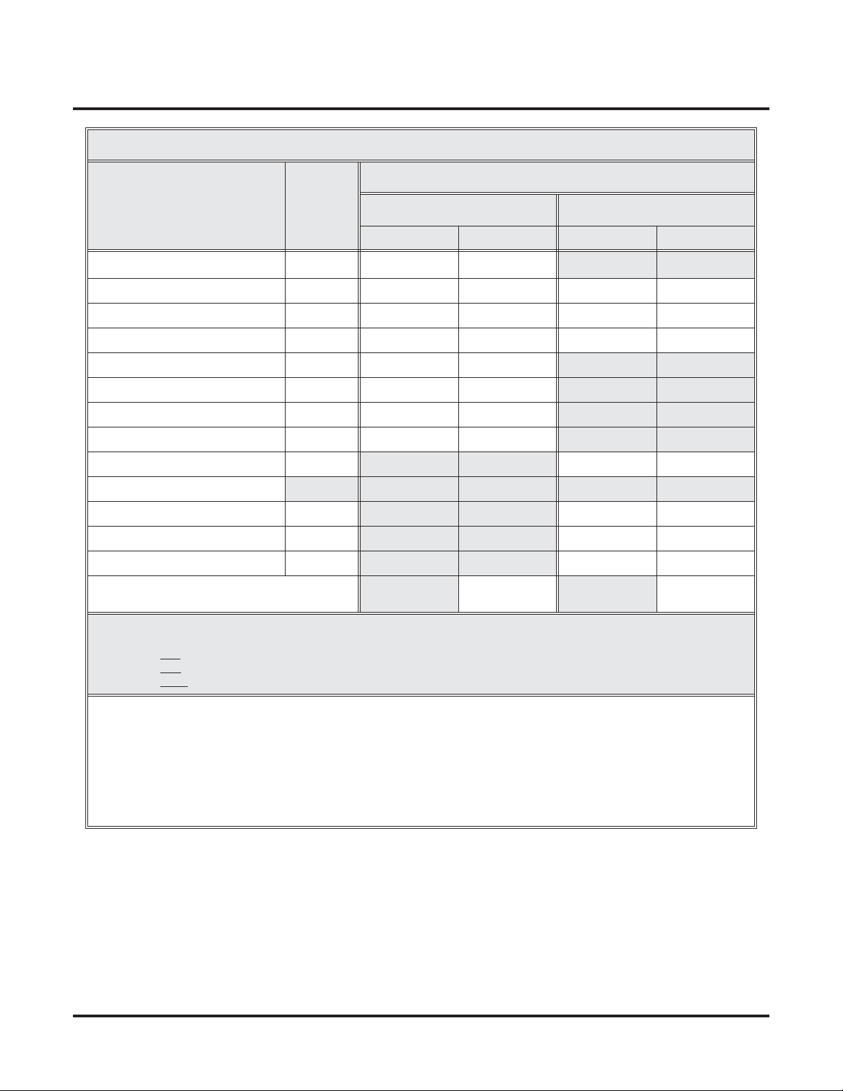
DS2000 System Load Factor Calculations
Load Type
Description Qty
CPU PCB 1 6 6 0 0
16DSTU PCB 3 20
4ASTU PCB 3 5
8ASTU PCB 5 8
4ATRU PCB 4 0
8ATRU PCB 8 0
T1 PCB 8 0
UltraMail PCB (FMS) 19 0
UltraMail 2000 PCB (VMS) 0 6
Telephones (Keysets and SLTs) 0 0
110-Button DSS Console 0 2
24-Button DSS Console 0 1
2-OPX Module 0 3
Item 1: Load Type Totals
(Cannot exceed Item 2: Power Supply Capacity.)
5 VDC 40 VDC
Load Total Load Total
Item 2: Power Supply Capacity
If you have one power supply installed, the capacity is:
If you have two power supplies installed, the capacity is:
If you have three power supplies installed, the capacity is:
Notes:
• A 4 slot cabinet can only have 1 power supply.
• An 8 slot cabinet can have up to 3 power supplies. You cannot have more than two 16DSTU PCBs per power sup-
ply, regardless of System Load Factor calculations.
• Exceeding the allowed Load Type Total (Item 1) will cause the system’s power supplies to automatically shut down
and/or cause erratic system operation.
• Total DSS Consoles installed cannot exceed 4.
• The total of all station, trunk, and UltraMail ports cannot exceed 112.
5 VDC = 40
5 VDC = 80
5 VDC = 120
40 VDC = 48
40 VDC = 80
40 VDC = 120
4 ◆ Chapter 1: Features DS1000/2000 Software Manual
Page 17

DS2000 System Configuration
Examples of Typical DS2000 4-Slot Cabinet Configurations
● 16 x 32 (16 trunks and 32 digital extensions)
Recommended for sites with no external Voice Mail and high trunk usage.
● 24 x 16 (24 trunks and 16 digital extensions)
Recommended for sites with no external Voice Mail and very high trunk usage.
●
8 x 16 x 16 (8 trunks, 16 digital extensions and 16 analog extensions)
Recommended for sites with external Voice Mail, normal trunk usage and high analog
extension usage.
●
16 x 16 x 8 (16 trunks, 16 digital extensions and 8 analog extensions)
Recommended for sites with external Voice Mail, high trunk usage and high analog extension usage.
● 8 x 32 x 8 (8 trunks, 32 digital extensions and eight analog extensions)
Recommended for sites with external Voice Mail, normal to low trunk usage and low analog
extension usage.
Examples of Typical DS2000 8-Slot Cabinet Maximum Configurations
● 32 x 64 (32 trunks and 64 digital extensions)
Recommended for sites with no external Voice Mail and high trunk usage. This configuration
requires 2 power supplies.
● 48 x 32 (48 trunks and 32 digital extensions)
Recommended for sites with no external Voice Mail and very high trunk usage. This configuration requires 1 power supply.
● 16 x 32 x 32 (16 trunks, 32 digital extensions and 32 analog extensions)
Recommended for sites with external Voice Mail, normal trunk usage and high analog extension usage. This configuration requires 2 power supplies.
● 32 x 32 x 16 (32 trunks, 32 digital extensions and 16 analog extensions)
Recommended for sites with external Voice Mail, high trunk usage and high analog extension
usage. This configuration requires 2 power supplies.
● 16 x 64 x 16 (16 trunks, 64 digital extensions and 16 analog extensions)
Recommended for sites with external Voice Mail, normal to low trunk usage and low analog
extension usage. This configuration requires 3 power supplies.
DS2000 Hardware Default Setup with Automatic Slot Configuration
Automatic Slot Configuration automatically sets up your system’s PCBs when you initially power
up the system. There is no longer a factory-installed default configuration, and you don’t have to
use system programming to activate PCBs after you plug them in. Remember, you should always
plug a 16DSTU PCB into slot CN1.
To take full advantage of all the new features and enhancements in software version 03.**.**,
always use the latest PCB versions.
DS1000/2000 Software Manual Chapter 1: Features ◆ 5
Page 18

DS1000 System Configuration
DS1000 System Configuration
DS1000 Load Factor
DS1000 System Load Factor Calculations
The combination of extensions, Digital Door Boxes, 2-OPX Modules, and DSS Consoles you can
connect to your system may be limited by the System Load Factor. Use the DS1000 System Load
Factor Calculations chart below to verify your system’s configuration.
To check your system configuration:
1. Indicate the quantity for each item installed in the
2. For each item, multiply the Qty times the Load Factor and enter the value in Total Load.
3. Add all the values in the Total Load column and enter the value in Item 1.
4. Compare the entry in Item 2 to your entry in Item 1. Item 1 must always be equal to or less
than the entry in
Do not operate your system if the System Load Factor total
(Item 1) exceeds the allowable load of 30 (Item 2).
Item 2.
Qty column.
DS1000 System Load Factor Calculations
Description Load Factor Qty Total Load
Digital Telephone and Digital
Door Box
Analog Telephone 1
Analog Door Box 0
24-Button DSS Console 1
110-Button DSS Console 2
Total DSS Consoles installed cannot exceed 4
2-OPX Module 3
Item 1: Total load for this configuration
Item 2: Maximum allowable load 30
1
6 ◆ Chapter 1: Features DS1000/2000 Software Manual
Page 19

DS1000 Default Setup
Using the factory installed default configuration, your DS1000 system provides:
Trunks 3 3 6
Digital Extensions 8 8 16
Analog Extensions 4 4 8
Analog Door Boxes 1 1 2
Relays 1 1 2
Page Output 1 - 1
Music Input 1 - 1
For more on installing the DS1000 Expansion PCB, refer to the DS1000 Quick Setup Guide (P/N
80200QSET**) that came with your system.
DS1000 System Configuration
Base Expansion Total
DS1000/2000 Software Manual Chapter 1: Features ◆ 7
Page 20

Initial System Startup
Initial System Startup
Default Feature Setup
Trunks
● All trunks are loop start DTMF.
Use Program 1001 - Trunk Circuit Type (page 699) to change this assignment.
● In DS2000, trunks 1-12 ring on line keys 1-12 for extensions 300-315. All other extensions
are lamp only for trunks 1-12. Trunks 13-64 do not appear on line keys.
● In DS1000, trunks 1-6 ring on line keys 1-6. (Trunks 4-6 require the Expansion Board.)
● Use User Programmable Features (page 577) code #RAL or Program 1805 - Ring Assign-
ments (page 767) to customize ringing.
Extensions
● The circuit types for keyset extensions are automatically set when the extension is plugged in.
Use Program 1801 - Extension Circuit Type (page 754) to change this assignment.
● Keyset users can place outside calls by:
- Pressing a line key and dialing the outside number.
See Central Office Calls, Placing (page 119) for more.
- Pressing
See Trunk Group Routing (page 566) for more.
● Line Dial-Up and Direct Trunk Access are disabled.
See Central Office Calls, Placing (page 119) for more.
● At the attendant’s extension (300), key 11 is the Night (System Mode System) key and the last
key on the phone (12 or 24, depending on telephone model) is the Operator Call Key.
Pressing the Night (System Mode System) key puts the system in the night mode. See
Night Service / Night Ring on page 389.
Use the Operator Call Key to answer incoming Intercom calls queued at the atten-
dant’s extension. See Attendant Call Queuing on page 35.
ICM, dialing 9, and dialing the outside number.
8 ◆ Chapter 1: Features DS1000/2000 Software Manual
Page 21
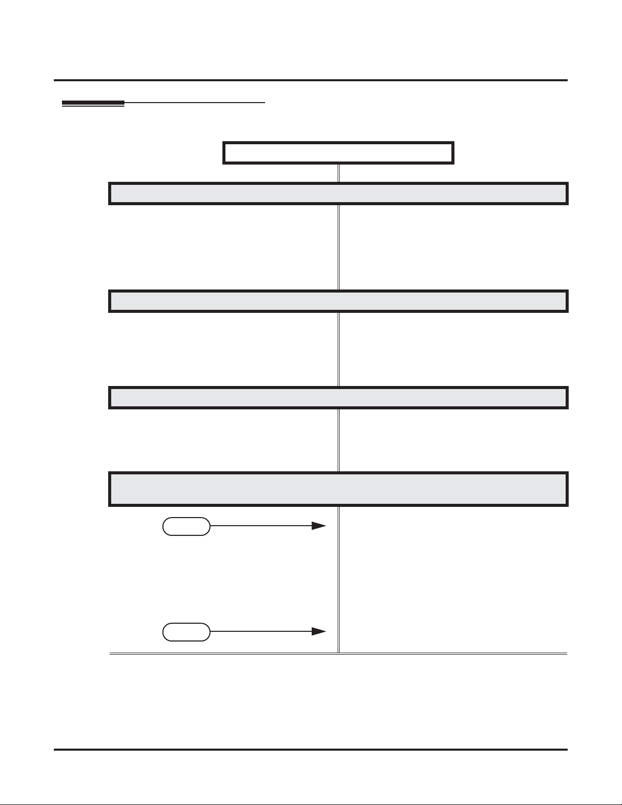
Initial Startup Programming
Initial Startup Programming (Page 1 of 2)
Step 1: Check the system defaults.
Step 2: Enter the programming mode.
Initial System Startup
• If you have a DS2000, refer to DS2000 Hardware
Default Setup with Automatic Slot Configuration
on page 5.
• If you have a DS1000, refer to DS1000 Default
Setup on page 7.
• To check the feature defaults, refer to Default
Feature Setup on page 8.
• From any display telephone:
ICM + #*#* + Password + HOLD.
Press
• The default system passwords are:
Installer (level 3) = 372000
System Administrator 2 (level 2) = 9999
System Administrator 3 (level 1) = 0000
Step 3: Assign the correct circuit type to your installed trunks.
• In Program 1001 - Trunk Circuit Type (page 699),
enter the correct circuit type for each installed
trunk. Analog trunk types are:
51 = Loop start DTMF
52 = Loop start DP
Step 4: By default, each extension has full access to each trunk. Do you want to change
this assignment?
• For each extension in Program 1803 - Extension
If yes
If no
Line Access Assignments (page 763), assign the
access options for each trunk. The options are:
0 = No access
1 = Incoming only
2 = Outgoing only
3 = Full access
• Use Program 9801 - Copy Command (page 786),
to simplify your programming.
• In Program 1803 - Extension Line Access Assign-
ments (page 763), make no changes from the
default assignments.
DS1000/2000 Software Manual Chapter 1: Features ◆ 9
Page 22
Initial System Startup
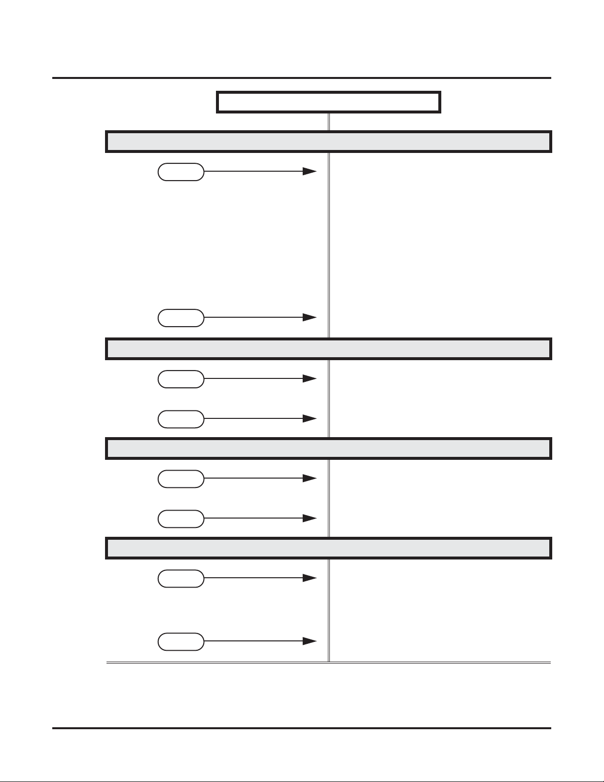
Step 5: Do you want to change the way extensions ring for incoming trunk calls?
If yes
If no
Step 6: Does your system have external Voice Mail?
Initial Startup Programming (Page 2 of 2)
• For each extension in Program 1805 - Ring
Assignments (page 767), assign ringing for each
trunk. The options are:
1 = Lamp only (day and night)
2 = Ringing day and night
3 = Night Ring only, lamp during the day
4 = Delay ring day and night
• Use Program 9801 - Copy Command (page 786),
to simplify your programming.
• The system attendant (extension 300) can put
these trunks in the night mode by pressing their
preassigned Night (System Mode System) key
(key 11).
• For each extension in Program 1805 - Ring
Assignments (page 767), make no changes from
the default assignments.
• Turn to Voice Mail on page 580 and review the
If yes
If no
Step 7: Do you want to change the default system passwords?
If yes
If no
Step 8: Do you want to return the system to its factory installed (default) programming?
If yes
If no
required Voice Mail programming.
• Go to the next step.
• In Program 9905 - Password (page 811), change
the passwords from their default settings.
• In Program 9905 - Password (page 811), do not
change the passwords from their default settings.
• In Program 9999 - System Initialization
(page 822), reinstate the factory installed programming. This erases all your programming
and returns the system to its initial default settings.
• In Program 9999 - System Initialization
(page 822), do not reinstate the factory installed
programming.
10 ◆ Chapter 1: Features DS1000/2000 Software Manual
Page 23

Charts and Illustrations
Charts and Illustrations
Table 1: Dial Codes (by Feature)
For this feature Dial this code When you are
Barge In (Intrusion) 4
Call Forwarding
ICM + ✽32 + Extension or 0 (for the
ICM + ✽34 + Extension or 0 (for the
ICM + ✽36 + Extension or 0 (for the
ICM + ✽37 + 2 (all calls) or 8 (out-
Call Waiting / Camp-On
Central Office Calls, Placing
ICM + #9
ICM + Trunk extension number (e.g.,
Barging-In on a co-worker’s call
✽30 Canceling Call Forwarding at an
ICM +
extension
Enabling Call Forwarding Busy/No
operator)
ICM + ✽33 Setting up Call Forwarding Off
Answer
Premise
Enabling Call Forwarding All Calls
operator)
Enabling Call Forwarding No Answer
operator)
Setting up Personal Answering
side calls)
+ Do not hang up
2
2 + Hang up
Leaving a Callback for a co-worker
Machine Emulation
Camping-On to a co-worker
+ Trunk number (e.g., 01) Using Line Dial-Up to place an out-
side call
Using Direct Trunk Access to place an
101)
outside call
ICM + 9 or 90-98 Accessing a Trunk Group to place an
Dial Number Preview
Directed Call Pickup
Flash #3
Forced Trunk Disconnect #
Group Call Pickup
Hold
Intercom
Meet-Me Conference
ICM
+ ✽✽ + Extension Intercepting a call ringing a
ICM
ICM
+ ✽4 + Trunk number (e.g., 01) Picking up an outside call on System
+ Extension (e.g., 301) Placing an Intercom call to a
ICM
+ #11 or # 12 Setting up or joining a Meet-Me Con-
ICM
outside call
✽ Previewing a number before dialing
co-worker’s extension
Flashing a trunk at a single line
extension
Using Forced Trunk Disconnect to
disconnect a busy outside line
+ ✽# Answering a call ringing a phone in
your Pickup Group
Hold at a co-worker’s extension
co-worker
ference
DS1000/2000 Software Manual Chapter 1: Features ◆ 11
Page 24

Charts and Illustrations
Table 1: Dial Codes (by Feature)
For this feature Dial this code When you are
Monitor / Silent Monitor 6
Night Service / Night Ring
Paging
Park
Removing Trunks and Extensions
From Service
Selectable Display Messaging
+ ✽1 + Page zone (1-7 or 0 for
ICM
+ ✽ + System Park Orbit (60-69) Parking or retrieving a call from Sys-
ICM
ICM + ✽✽ + Extension (e.g., 301)
ICM
+ #40 + Extension (e.g., 301) or
trunk (e.g., 101) + 4 (to return) or 6
+ ✽38 + Message (00-16) + Hold
ICM
+ Add additional digits + Hold
Speed Dial
Transfer
+ # + System bin (200-299) or
ICM
ICM
ICM + Extension (e.g., 301) + MW
Setting up Monitor after calling a busy
co-worker
✽✽ + UNA code (01-04) Answering a call ringing UNA at
night
Making an internal Paging announce-
All Call)
ment
tem Park Orbit
Using Personal Park to Park or retrieve
a call at a co-workers extension
Removing or returning an extension or
trunk to service
(to remove)
Enabling a Selectable Display Message
Dialing a System or Personal Speed
Personal bin (701-720)
+ Extension (e.g., 301)
Transferring a call to a co-worker’s
Dial number
extension
Transferring a call to a co-worker’s
mailbox
Trunk (Line) Queuing / Trunk Call-
back
Voice Mail
Voice Over 9
2
Queuing or leaving a Callback for a
busy trunk
+ MW
ICM
Lift handset + ✽8
Calling your mailbox from your keyset
Calling your mailbox from your single
line telephone
ICM + Extension (e.g., 301) + MW
Transferring a call to a co-worker’s
mailbox from your keyset
Hookflash + Extension (e.g., 301) + 8 Transferring a call to a co-worker’s
mailbox from your single line
ICM + ✽37 + 2 (all calls) or 8 (outside
calls)
ICM + ✽30 Canceling Personal Answering
Setting up Personal Answering
Machine Emulation
Machine Emulation
Initiating a Voice Over to a busy exten-
sion (after hearing busy/ring tone)
12 ◆ Chapter 1: Features DS1000/2000 Software Manual
Page 25
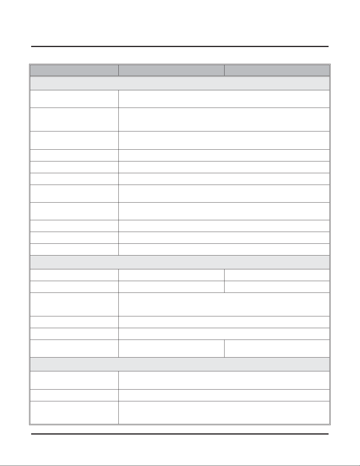
Charts and Illustrations
Table 2: System Number Plan/Capacities (Page 1 of 2)
DS1000 DS2000
System Options
• Classes of Service 1-15
(COS 1 normally reserved for attendants)
• Conference 32 simultaneous users in Conference (total of all Conferences system-wide)
8 simultaneous Conferences maximum
8 parties maximum in any one Conference
• Extension Hunting (ACD/
UCD) Master Numbers
• Extension Hunting Groups 8 (1-8)
• Group Call Pickup Groups 8 (1-8, 0 = unassigned)
• Privacy Release Groups 16 (1-16, 0 = unassigned)
• Speed Dial, Personal 20 bins at each extension (701-720)
See
Speed Dial (page 481)
• Speed Dial. System
See
Speed Dial (page 481)
• Tenant Groups 1
• Timeslots Non-blocking
• Toll Restriction Levels 7 (1-7, 0 = no restriction)
Trunks
• Direct Trunk Access Codes 101-106 101-164
• Line Dial Up Codes #901-#906 #901-#964
• Ring Groups 8 (1-8)
10 (20-29), 100 (200-299), 1000 (2000-2999)
Ring Group master numbers are normally 600-607.
for additional information on Speed Dial capacities.
for additional information on Speed Dial capacities.
0 = No assignment
8
• Trunk Group Access Codes 90-98
• Trunk Groups 9 (0-8)
• Trunk Ports 6 (1-6)
Trunks 4-6 require the Expansion Board.
Extensions
• Attendant (Operator) Access
Number
• Attendants 4
• 2-OPX Modules
DS1000/2000 Software Manual Chapter 1: Features ◆ 13
Each 2-OPX Module uses one digital station port. The System Load Factor may limit the
total number you can install. See
0 (single operator)
01-04 (multiple operators)
DS2000 Load Factor on page 3
tor on page 6
.
64 (1-64)
and
DS1000 Load Fac-
Page 26
Charts and Illustrations
Table 2: System Number Plan/Capacities (Page 2 of 2)
DS1000 DS2000
• Digital Door Boxes
• Analog Door Boxes 2
• DSS Consoles 4
• Telephone Extension Numbers 300-333 (which includes digital exten-
• Telephone Station Numbers 34 (1-34) 128 (1-128)
• Total Number of Station
Devices
• UCD Hunting Master Numbers
• Voice Mail Master Numbers 1 (normally 700)
• External Voice Mail Ports Limited by available analog and digital station ports.
Each Digital Door Box uses one digital station port. The System Load Factor may limit the
total number you can install. See
2nd Analog Door Box requires Expansion
PCB
The System Load Factor may limit the total number that you can install.
Load Factor on page 3
sions 300-315, analog extensions 31-323,
and Analog Door Boxes 324 and 325)
34 (which includes digital extensions
300-315, analog extensions 316-323, and
Analog Door Boxes 324 and 325)
Master numbers are normally 700-707.
DS2000 Load Factor on page 3
tor on page 6
and
DS1000 Load Factor on page 6
8 (1-8)
.
128 (may be limited by load factor)
and
DS1000 Load Fac-
N/A
300-427
See
.
DS2000
Paging and Park
• Page Zones (Internal) 7 zones (1-7) and All Call (0)
• Page Zone (External) All Call and zone 1 broadcast from Audio
jack (AUDIO)
• Page Relays One set in each Analog Door Box jack
(DOOR1 and DOOR2)
• Park Orbits 10 (60-69)
Orbits 68 and 69 have extended (5 min.) timers
Passwords
• System Administrator 1
(Level 1)
• System Administrator 2
(Level 2)
• Installer (Level 3) 372000
0000
9999
14 ◆ Chapter 1: Features DS1000/2000 Software Manual
Page 27
80000 -70
Charts and Illustrations
CLEAR
CHECK
LINE 1 LINE 2 LINE 3 LINE 4 LINE 5 LINE 6
LINE 7 LINE 8
BIN 1 BIN 2 BIN 3 BIN 4 BIN 5
BIN 6 BIN 7 BIN 8 BIN 9 BIN 10
LINE 9 LINE 10 LINE 11 LINE 12
ABC DEF
MW ICM
1 2 3
GHI JKL MNOMNO
FLASH DND
4 5 6
PQRS TUV
WXYZ
DIAL MIC
7 8 9
OPER
LND SPK
0
VOL
CONF
HOLD
In DS1000:
Keys 7-12 are
undefined.
For Attendants:
Key 11=Night Key
Key 12=Operator Call Key
Figure 1: 22-Button Display Telephone
DS1000/2000 Software Manual Chapter 1: Features ◆ 15
Page 28
Charts and Illustrations
80000 - 63A
CLEAR
CHECK
LINE 1 LINE 2 LINE 3 LINE 4 LINE 5 LINE 6
LINE 7 LINE 8
LINE 9 LINE 10 LINE 11 LINE 12
In DS1000:
Keys 7-12 are
undefined.
ABC DEF
1 2 3
GHI JKL MNOMNO
4 5 6
PQRS TUV
WXYZ
7 8 9
OPER
0
VOL
MW ICM
FLASH DND
DIAL MIC
LND SPKR
CONF
HOLD
For Attendants:
Key 11=Night Key
Key 12=Operator Call Key
Figure 2: 22-Button Standard Telephone
16 ◆ Chapter 1: Features DS1000/2000 Software Manual
Page 29
80000 - 72
Charts and Illustrations
CLEAR
CHECK
LINE 1 LINE 2 LINE 3 LINE 4 LINE 5 LINE 6
LINE 7 LINE 8
BIN 1 BIN 2 BIN 3 BIN 4 BIN 5
BIN 6 BIN 7 BIN 8 BIN 9 BIN 10
LINE 9 LINE 10 LINE 11 LINE 12
ABC DEF
MW ICM
1 2 3
GHI JKL MNOMNO
FLASH DND
4 5 6
PQRS TUV
WXYZ
DIAL MIC
7 8 9
OPER
LND SPK
0
VOL
CONF
HOLD
For Attendants:
Key 11=Night Key
Key 24=Operator Call Key
Keys 13-24 are undefined
for non-attendants in DS2000.
Keys 7-24 are undefined for
non-attendants in DS1000.
Figure 3: 34-Button Display Telephone
DS1000/2000 Software Manual Chapter 1: Features ◆ 17
Page 30
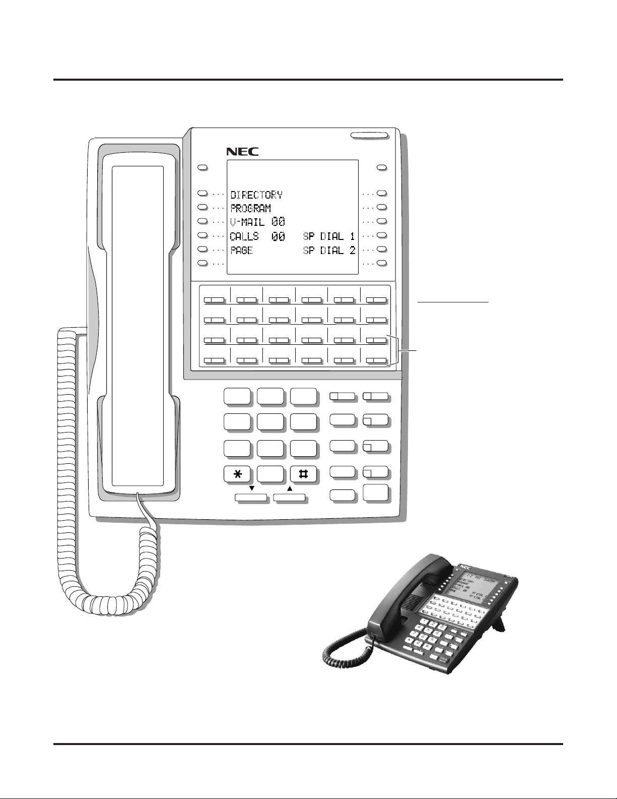
Charts and Illustrations
80000 - 71
CHECK CLEAR
LINE 1 LINE 2 LINE 3 LINE 4 LINE 5 LINE 6
LINE 7 LINE 8
1
GHI JKL MNO
4
PQRS TUV
7
LINE 9 LINE 10 LINE 11 LINE 12
ABC DEF
2
5
WXYZ
8
OPER
3
6
9
MW ICM
FLASH DND
DIAL MIC
LND SPKR
0
VOL
CONF
HOLD
For Attendants:
Key 11=Night Key
Key 24=Operator Call Key
Keys 13-24 are undefined
for non-attendants in DS2000.
Keys 7-24 are undefined for
non-attendants in DS1000.
Figure 4: 34-Button Super Display Telephone
18 ◆ Chapter 1: Features DS1000/2000 Software Manual
Page 31

80000 - 25
Charts and Illustrations
300 312
301 313
302 314
303 315
304 316
305 317
306 318
307 319
308 320
309 321
310 322
311 323
Figure 5: 24-Button DSS Console
DS1000/2000 Software Manual Chapter 1: Features ◆ 19
Page 32

Charts and Illustrations
80000 - 74
300 301 302 303 304 305 306 307 308 309
310 311 312 313 314 315 316 317 318 319
320 321 322 323 324 325 326 327 328 329
330 331 332 333 334 335 336 337 338 339
340 341 342 343 344 345 346 347 348 349
350 351 352 353 354 355 356 357 358 359
360 361 362 363 364 365 366 367 368 369
370 371 372 373 374 375 376 377 378 379
380 381 382 383 384 385 386 387 388 389
390 391 392 393 394 395
PARK 0 PARK 1 PARK 2 PARK 3 PARK 4 PARK 5 PARK 6 PARK 7 PARK 8 NIGHT
PAGE 1 PAGE 2 PAGE 3
PAGE
ALL
Figure 6: 110-Button DSS Console (DS2000)
20 ◆ Chapter 1: Features DS1000/2000 Software Manual
Page 33

80200 - 56
Charts and Illustrations
300 301 302 303 304 305 306 307 308 309
310 311 312 313 314 315 316 317 318 319
Hotlines
to
Extensions
320 321 322 323 324 325 326 327 328 329
330 331 332 333
PARK 0 PARK 1 PARK 2 PARK 3 PARK 4 PARK 5 PARK 6 PARK 7 PARK 8 NIGHT
Note: Blank keys are undefined.
401 402
PAGE 1 PAGE 2 PAGE 3
PAGE
ALL
Figure 7: 110-Button DSS Console (DS1000)
DS1000/2000 Software Manual Chapter 1: Features ◆ 21
Page 34

2-OPX Module
2-OPX Module
Description
DS1000/2000
Available. See see Off-Premise Extensions / On-Premise SLT Extensions on
page 399.
22 ◆ Chapter 1: Features DS1000/2000 Software Manual
Page 35

2500 Sets / Single Line Telephones
2500 Sets / Single Line Telephones
Description
DS1000/2000
Available. See see Off-Premise Extensions / On-Premise SLT Extensions on
page 399.
DS1000/2000 Software Manual Chapter 1: Features ◆ 23
Page 36

Account Codes
Account Codes
Description
DS1000/2000 Available.
Use Account Codes to categorize and/or restrict outside calls.
Account Codes are user-dialed codes that help categorize and/or restrict trunk calls. Account
Codes are from 2-10 digits long, using any combination of the digits 0-9. There are three types of
Account Codes:
● Optional (Unforced Account Codes)
● Forced Account Codes
● Verified Account Codes
Optional (Unforced) Account Codes
Optional Account Codes allow a keyset extension user to enter an Account Code while placing a
trunk call or any time while on a call. This type of Account Code is optional: the system does not
require the user to enter it. If the keyset user is already talking on a trunk call, their conversation
continues uninterrupted while they enter an Account Code.
Single line telephone users can only enter an Account Code while placing their trunk call.
Forced Account Codes
Forced Account Codes require an extension user to enter an Account Code every time they place a
trunk call. If the user doesn’t enter the code, the system prevents the call. The system can require
Forced Account Codes for all trunk calls, or just for toll calls (as determined by Toll Restriction
programming). Note that Forced Account Codes do not pertain to incoming calls.
Verified Account Codes
With Verified Account Codes, the system compares the Account Code the user dials with a list of
codes programmed into the Verified Account Code Table. If the Account Code is in the table, the
call goes through (provided it is not prevented by an extension’s Toll Restriction programming). If
the code is not in the table, the system prevents the call. Verified Account Codes, if enabled, apply
only to Forced Account Codes.
Using Account Codes and Speed Dial
To simplify Account Code operation, Personal and System Speed Dial bins can contain Account
Codes. Keep the following in mind when using Speed Dial and Account Codes:
● The Account Code can be either the first or last entry in the bin, and must be preceded and fol-
lowed by the # character. For example, the Account Code 1234 must be entered as #1234#.
● The Program 0201 - # Key to Enter Account Codes (page 629) option must be enabled in sys-
tem programming. In addition, the Program 0201 - Enable Account Codes in Speed Dial
(page 629) option must also be enabled.
●
The Speed Dial bin can contain an Account Code followed by an outside number, or just the
Account Code. The Account Code must be preceded and followed by a # entry. If the bin
contains just the Account Code, the user must be sure to press the bin key before dialing the
outside number.
● If the system has Verified Account Codes enabled, the Account Code entered in the Speed
Dial bin must match an entry in the Verified Account Code Table.
24 ◆ Chapter 1: Features DS1000/2000 Software Manual
Page 37

Account Codes
● If the Speed Dial bin does not contain an Account Code, the user must enter the Account Code
manually. If Forced Account Codes are enabled, the system requires
Account Code before it outdials the stored Speed Dial number.
● An extension user can preselect a trunk for a Speed Dial call.
Using Account Codes with Last Number Redial and Save
Last Number Redial and Save do not store Account Codes. This means that the user must manually
enter an Account Code to have it included with a call dialed using Last Number Redial and Save. If
Forced Account Codes are enabled, the system requires
outdials the stored number saved by Last Number Redial or Save.
An extension user can preselect a trunk for a Last Number Redial or Save call.
the user to enter the Account Code before it
Account Codes and Emergency Calls
Account Codes are never enforced for emergency (911 and 1+911) calls.
DSS Console Account Code Key
A keyset user can have an Account Code key on their DSS Console. It works the same as a keyset
Account Code key with the following exceptions:
● The DSS Console key flashes quickly red while the user is entering their Account Code. (The
keyset Account Code key flashes quickly green.)
● The DSS Console key lights red while the user is on a call for which they have entered an
Account Code. (The keyset Account Code key lights green.)
the user to enter the
Conditions
Do not use Account Codes that begin with 911 or 1911.
Default Setting
Account Codes disabled.
DS1000/2000 Software Manual Chapter 1: Features ◆ 25
Page 38

Account Codes
Programming Guide
Step 1: Should users be able to store Account Codes in Speed Dial bins?
Step 2: While on an outside call, should an extension user be able to dial # to enter an
Account Code?
If yes
If no
If yes
Step-by-step guide for setting up
Account Codes (Page 1 of 3)
• In Program 0201 - Enable Account Codes in
Speed Dial (page 629), enter Y.
• In Program 0201 - Enable Account Codes in
Speed Dial (page 629), enter N. Any Account
Codes stored in Speed Dial bins dial out as part of
the stored number.
• In Program 0201 - # Key to Enter Account Codes
(page 629), enter Y.
• In Program 0201 - # Key to Enter Account Codes
If no
Step 3: Should Account Code entries be hidden (i.e., replaced by * characters) on each tele-
phone’s display?
If yes
If no
Step 4: Should a keyset have an Account Code key to simplify entering Account Codes?
If yes
If no
(page 629), enter N.
• In Program 0201 - View Account Codes
(page 630), enter N.
• In Program 0201 - View Account Codes
(page 630), enter Y.
• In Program 1701 - Programmable Function Key
Assignments (page 737), enter 26 to assign a key
as an Account Code key.
• In Program 1701 - Programmable Function Key
Assignments (page 737), do not assign a key with
code 26.
26 ◆ Chapter 1: Features DS1000/2000 Software Manual
Page 39

Account Codes
Step-by-step guide for setting up
Account Codes (Page 2 of 3)
Step 5: Should a DSS Console have an Account Code key to simplify entering Account
Codes?
• In Program 1704 - DSS Console Key Assignment
If yes
If no
Step 6: Should an extension have Forced Account Codes (i.e., be required to enter an
Account Code while placing a call)?
If yes
(page 746), enter 26 to assign a key as an Account
Code key.
• In Program 1704 - DSS Console Key Assignment
(page 746), do not assign a key with code 26.
• In Program 0101 - Forced Account Codes
(page 620), enter Y.
• Program 1801 - Extension Class of Service
Assignment (page 755), assign Class of Service to
extensions.
• In Program 1001 - Disable Forced Account Codes
(page 703), enable No (N) to have the system
enforce Forced Account Codes for the trunk.
OR
In Program 1001 - Disable Forced Account Codes
(page 703), enable Yes (Y) to have the system not
enforce Forced Account Codes for the trunk.
• In Program 0101 - Forced Account Codes
If no
Step 7: Should an extension have Forced Account Codes just for long distance (toll) calls?
If yes
If no
(page 620), enter N.
• Program 1801 - Extension Class of Service
Assignment (page 755), assign Class of Service to
extensions.
• In Program 0101 - Forced Account Codes for Toll
Calls Only (page 621), enter Y.
• In Program 0201 - Account Code Toll Level
(page 629), enter the toll level (0-7) the system
will use to determine toll calls. See Forced
Account Codes Programming on page 29 for
more on setting this up.
• Program 1801 - Extension Class of Service
Assignment (page 755), assign Class of Service to
extensions.
• In Program 0101 - Forced Account Codes for Toll
Calls Only (page 621), enter N.
• Program 1801 - Extension Class of Service
Assignment (page 755), assign Class of Service to
extensions.
DS1000/2000 Software Manual Chapter 1: Features ◆ 27
Page 40

Account Codes
Step 8: Should an extension have Verified Account Codes (i.e., be required to enter an
Account Code from the Verified Account Codes Table while placing a call)?
If yes
If no
Step-by-step guide for setting up
Account Codes (Page 3 of 3)
• In Program 0101 - Verify Account Codes
(page 621), enter Y.
• In Program 1201 - Verified Account Codes Table
(page 721), enter codes into the Verified Account
Codes table.
• In Program 1801 - Extension Class of Service
Assignment (page 755), assign Class of Service to
extensions.
• In Program 0101 - Verify Account Codes
(page 621), enter N.
• Program 1801 - Extension Class of Service
Assignment (page 755), assign Class of Service to
extensions.
Programming List
General Account Codes Programming
Program 0201 - Enable Account Codes in Speed Dial (page 629)
Enable (Y) this option if users should be able to store Account Codes in Speed Dial bins. This
causes the stored Account Code to properly display in the SMDR report Account column. If
you disable (N) this option, Account Codes stored in Speed Dial bins dial out as part of the
stored number and display in the SMDR report Number Dialed column. They will not display
in the Account column. This option is disabled by default.
Program 0201 - # Key to Enter Account Codes (page 629)
Use this option to enable (Y) an extension user to dial # to enter an Account Code while on an
outside call. If disabled (N), the extension user can only enter an Account Code by pressing
the Account Code soft key or a uniquely programmed Account Code Programmable Function
Key. This option is disabled by default.
Program 0201 - View Account Codes (page 630)
Use this option to show or hide the Account Codes a user enters on their telephone’s display.
If enabled (Y), the dialed Account Codes show on the display. This may be a security risk,
since a co-worker can easily read the telephone display as the user enters their Account
Code. If disabled (N), Account Codes are shown as * characters on the telephone display. This
option is disabled by default.
Program 1701 - Programmable Function Key Assignments (page 737)
Use this option to assign an Account Code Programmable Function Key to a keyset (code 26).
There are no Account Code Programmable Function Keys assigned by default.
Program 1704 - DSS Console Key Assignment (page 746)
Use this option to assign an Account Code Programmable Function Key to a DSS Console
(code 26). There are no Account Code Programmable Function Keys assigned by default.
Optional (Unforced) Account Codes Programming
Optional Account Codes are always available without programming.
28 ◆ Chapter 1: Features DS1000/2000 Software Manual
Page 41

Forced Account Codes Programming
Program 0101 - Forced Account Codes (page 620)
Use this option to enable (Y) or disable (N) Forced Account Codes. If disabled, Optional
Account Codes are still available. This option is disabled by default.
Program 0101 - Forced Account Codes for Toll Calls Only (page 621)
●
Use this option to enable (Y) Forced Account Codes only for toll (long distance) calls. If
disabled (N), Forced Account Codes apply to all outgoing trunk calls. This option is disabled by default (i.e., Forced Account Codes, if enabled, apply to all outgoing trunk calls).
●
The system identifies toll calls according to the settings in
Toll Level (page 629)
●
If
Program 0101 - Forced Account Codes (page 620)
Forced Account Codes for Toll Calls Only (page 621)
Program 0201 - Account Code Toll Level (page 629)
If Program 0101 - Forced Account Codes for Toll Calls Only (page 621) is enabled, use this
option to differentiate toll calls from local calls for Account Code purposes. If you enter 0 for
this option, toll calls are any calls the user dials that begin with 0 or 1. If you enter a toll level
for this option (1-7), the system uses the toll level options programmed in 0601 - Configure
Toll Level Options on page 683 for that level to determine if the call is local or toll.
●
If the toll level is set to deny the call, it is considered to be a long distance call and the system requires that the user must have entered an Account Code.
●
If the toll level permits the call, it is considered to be a local call and no Account Code
entry is required.
●
Note that additional dialing restrictions enforced by an extension’s toll level (set in
gram 1801 - Extension Toll Level Day (page 755)
Level Night (page 755)
Program 1001 - Disable Forced Account Codes (page 703)
Use this option to enable or disable Forced Account Codes for an individual trunk. If enabled
(Y), the system will not enforce Forced Account Codes for the trunk. If disabled (N), the system will enforce Forced Account Codes for the trunk.
Program 1801 - Extension Class of Service Assignment (page 755)
Assign Class of Service to extensions.
programming below.
and
are in effect and may also restrict dialing.
Account Codes
Program 0201 - Account Code
is disabled, the
option has no effect.
Program 1801 - Extension Toll
Program 0101 -
Pro-
Verified Account Codes Programming
Program 0101 - Verify Account Codes (page 621)
Use this option to enable (Y) or disable (N) Verified Account Codes. If enabled, the system
compares the Account Code the user dials to the entries in 1201 - Verified Account Codes
Table on page 721. There are no entries in this table by default.
Program 1201 - Verified Account Codes Table (page 721)
●
Use this option to enter codes into the Verified Account Codes Table. When
- Verify Account Codes (page 621)
user dials to the entry in this table. If the entries match, the system allows the call (provided it is not prevented by an extension’s Toll Restriction). If there is no match, the system denies the call.
●
A Verified Account Code can be from 1 to 10 digits long, using the digits 0-9. You can use
the * character as a wild card, which can be entered in any position in a Verified Account
Code. A wild card allows the user to dial any digit in that position. For example, the entry
11*1 represents entries 1101, 1111, 1121, etc.
●
DS1000 provides for 500 table entries. DS2000 provides for 1000 table entries.
●
Do not enter either 911 or 1911 into the Verified Account Codes Table. When a user
presses a line key and dials either 911 or 1911, the system immediately bypasses all Toll
Restriction and Account Code programming and routes the call.
Program 1801 - Extension Class of Service Assignment (page 755)
Assign Class of Service to extensions.
is enabled, the system compares the Account Code the
Program 0101
DS1000/2000 Software Manual Chapter 1: Features ◆ 29
Page 42

Account Codes
Account Codes Programming Examples
Example 1: Forced Account Codes Require an Account Code only for 900 and
1 + 900 Long Distance Dialing
To set up Forced Account Codes to require entries for only 900 and 1 + 900 calls:
1. In 0101 - Forced Account Codes, enter Y.
2. In 0101 - Forced Account Codes for Toll Calls Only, enter Y.
3. In 0201 - Account Code Toll Level, enter 2 (for example).
4. In 0601 - Initialize Toll Restriction, be sure to initialize the Toll Restriction tables.
Make the following entries for Toll Restriction Level 2.
5. In 0601 - Active Dial Pad, enter Y (enabled).
6. In 0602 - 1010 + XXX Equal Access Dialing, make a deny table with no entries (i.e., deny
7. In 0603 - 1 + NPA /NXX Dialing 3-Digit Table, make a deny table and enter 900.
8. In 0604 - 1 + NPA + NXX Dialing 6-Digit Table, make a deny table with no entries (i.e.,
9. In 0605 - NPA/NXX Dialing 3-Digit Table, make a deny table and enter 900.
10. In 0606 - NPA + NXX Dialing 6-Digit Table, make no entries (i.e., deny nothing). This is the
11. In 1801 - Extension Class of Service, assign the Class of Service with Forced Account Codes
12. In 1801 - Extension Toll Level Day and 1801 - Extension Toll Level Night, be sure the
In 0601 - N11 Dialing, enter Y (enabled).
In 0601 - 0+ Dialing, enter Y (enabled).
In 0601 - Equal Access (101X + XXX) Dialing, enter Y (enabled).
nothing). This is the default setting.
deny nothing). This is the default setting.
default setting. This table is permanently assigned as a deny table.
enabled to the extension.
extension does not use Toll Level 2. If it does, Toll Restriction will always deny 1 + 900 and
900 calls (regardless of whether the user enters an Account Code).
An extension user can then:
1. Press a line key or dial a code for an outside line.
2. Wait for reminder tone (3 beeps).
With Forced Account Codes enabled, the system automatically goes into the Account
Code mode after you press a line key in step 1 above.
If you have an Account Code Programmable Function Key, it flashes green.
3. If dialing a 1 + 900 or 900 call
If dialing any other long distance call, skip this step.
4. Press # (if enabled), the Account Code soft key, or an Account Code Programmable Function
Key (if programmed).
5. Dial the outside number.
If the user doesn’t enter an Account Code for 900 or 1 + 900 calls, the system will cut
off the call.
The system will also cut off any call not allowed by the extension’s Toll Restriction pro-
gramming.
30 ◆ Chapter 1: Features DS1000/2000 Software Manual
, dial the Account Code.
Page 43

Account Codes
Example 2: Forced Account Codes Allow 800 and 1 + 800 Long Distance Dialing
Without an Account Code
To set up Forced Account Codes to require entries for all calls except 800 and 1 +
800 Dialing:
1. In 0101 - Forced Account Codes, enter Y.
2. In 0101 - Forced Account Codes for Toll Calls Only, enter Y.
3. In 0201 - Account Code Toll Level, enter 2 (for example).
e the following entries for Toll Restriction Level 2.
Mak
4. In 0601 - Active Dial Pad, enter Y (enabled).
In 0601 - N11 Dialing, enter Y (enabled).
In 0601 - 0+ Dialing, enter Y (enabled).
In 0601 - Equal Access (101X + XXX) Dialing, enter Y (enabled).
5. In 0602 - 1010 + XXX Equal Access Dialing, make a deny table with no entries (i.e., deny
nothing). This is the default setting.
6. In 0603 - 1 + NPA /NXX Dialing 3-Digit Table, make an allow table and enter 800.
7. In 0604 - 1 + NPA + NXX Dialing 6-Digit Table, make a deny table with no entries (i.e.,
deny nothing). This is the default setting.
8. In 0605 - NPA/NXX Dialing 3-Digit Table, make an allow table and enter 800.
9. In 0606 - NPA + NXX Dialing 6-Digit Table, make no entries (i.e., deny nothing). This is the
default setting. This table is permanently assigned as a deny table.
10. In 1801 - Extension Class of Service, assign the Class of Service with Forced Account Codes
enabled to the extension.
An extension user can then:
1. Press a line key or dial a code for an outside line.
2. Wait for reminder tone (3 beeps).
With Forced Account Codes enabled, the system automatically goes into the Account
code mode after you press a line key in step 1 above.
If you have an Account Code Programmable Function Key, it flashes green.
3. If dialing a 1 + 800 or 800 call
If dialing any other long distance call, dial the Account Code.
4. Press # (if enabled), the Account Code soft key, or an Account Code Programmable Function
Key (if programmed).
5. Dial the outside number.
The call will go through without an Account Code. If the user doesn’t enter an Account
Code for all other calls, the system will cut off the call.
The system will also cut off any call not allowed by the extension’s Toll Restriction pro-
gramming.
, skip this step.
DS1000/2000 Software Manual Chapter 1: Features ◆ 31
Page 44

Account Codes
Other Related Features
Central Office Calls, Placing (page 119)
Last Number Redial (page 351) and Save Number Dialed (page 468)
Speed Dial (page 481)
Station Message Detail Recording (page 498)
Voice Mail (page 580)
Feature Operation
To enter an Optional (Unforced) Account Code:
1. Place or answer outside call.
2. Press Account Code soft key, Programmable Function Key, or dial # (if enabled).
3. Enter Account Code (up to 10 digits long, using the digits 0-9).
4. Press Account Code soft key, Programmable Function Key, or dial # (if enabled).
5. For Outgoing Calls Only
You can use Store and Forward with Forced Account Codes. See Store and Forward with
Forced Account Codes on page 120 for more.
Last Number Redial and Save do not store Account Codes. This means that the user must
manually enter an Account Code to have it included with a call dialed using Last Number
Redial and Save.
An extension user can store an Account Code in a Speed Dial bin. See Using Account Codes
and Speed Dial on page 24 for more.
Account Codes print on the SMDR report.
Voice Mail callout features (such as Message Notification) may interact with Account Codes
if the callout number contains # characters.
For keysets, Optional Account Codes apply to both incoming and outgoing calls. For
outgoing calls, you can enter the Account Code before or after dialing the outside number.
For Single Line sets, Optional Account Codes apply only to outgoing calls. You must enter
the Account Code after getting dial tone on the trunk but before dialing the outside number.
Dial your outside number.
Toll Restriction may still prevent you from dialing certain outside numbers.
To enter a Forced Account Code:
Forced Account Codes do not apply to incoming calls.
1. Access a line for an outgoing call.
Three beeps.
Your telephone display prompts you to enter an Account Code.
2. Enter Account Code (up to 10 digits long, using the digits 0-9).
If your system has Verified Account Codes enabled, you must
fied Account Codes Table. If you enter an invalid Verified Account Code, your call will be
cut off in the next step.
3. Press Account Code soft key, Programmable Function Key, or dial # (if enabled).
Dial tone on your outside line.
N/A.
4. Dial your outside number.
Toll Restriction may still prevent you from dialing certain outside numbers.
32 ◆ Chapter 1: Features DS1000/2000 Software Manual
enter one from the Veri-
Page 45

Alphanumeric Display
Alphanumeric Display
Description
DS1000/2000 Available.
The Alphanumeric Display messages help the display telephone user process calls, identify callers
and customize features.
The 22- and 34-Button Display Telephones have a two-line, 20-character per line alphanumeric display. The first line displays the date and time (while idle) and feature status messages. The second
line displays the Soft Key definitions.
The 34-Button Super Display Telephone has an eight-line, 20-character per line alphanumeric display. The first line displays the date and time (while idle) and feature status messages, just like the
22- and 34-Button Display Telephones. Lines 2-8 are the comprehensive Super Display Telephone
soft key definitions.
● To learn more about the display telephones:
- see 22-Button Display Telephone on page 15
- see 34-Button Display Telephone on page 17
- see 34-Button Super Display Telephone on page 18
● To learn more about the Soft Keys, see Soft Keys on page 480.
Conditions
None
Default Setting
Enabled for all display telephones.
Programming Guide
None
Programming List
None
Other Related Features
Soft Keys (page 480)
The interactive Soft keys provide users with intuitive access to the telephone’s features.
Volume Controls (page 603)
While a feature is active, pressing VOL
While a 22-Button or 34-Button Display telephone is idle, pressing VOL
adjusts the display contrast. Note that 34-Button Super Display Telephones do not provide
contrast adjustments. A system reset or power down returns the user-set contrast setting to a
median level.
▲ and VOL ▼ adjusts the volume of the active feature.
▲ and VOL ▼
DS1000/2000 Software Manual Chapter 1: Features ◆ 33
Page 46

Alphanumeric Display
Feature Operation
Refer to the individual features for feature operation.
34 ◆ Chapter 1: Features DS1000/2000 Software Manual
Page 47

Attendant Call Queuing
Attendant Call Queuing
Description
DS1000/2000 Available.
Attendant Call Queuing helps minimize call congestion in systems that use the attendant as the
overflow destination for unanswered calls.
An unlimited number of callers can queue for the attendant. The callers hear ringback while they
wait for the attendant to answer — not busy tone. If you have the attendant as the overflow destination for Direct Inward Lines, for example, unanswered DILs will “stack up” at the attendant until
they are answered
Operator Call Key
The last programmable key on an attendant telephone is permanently assigned as an Operator Call
Key. When the operator has Intercom calls waiting to be answered, the calls queue under this key.
The key winks (on) when calls are queued.
The Operator Call Key is a permanent assignment for all extensions assigned as operators. You cannot change this assignment. Attendant Call Queuing is a permanent, non-programmable feature.
Conditions
None
Default Setting
At attendant (extension 300 by default), key 12 (on 22-button) or key 24 (on 34-button) is an Operator Call Key.
Programming Guide
None
Programming List
None
Other Related Features
Attendant Position (page 37)
Assign system attendants.
Call Coverage Keys (page 59)
A Call Coverage Key will not pick up a call ringing the attendant’s Operator Call Key.
Off-Hook Signaling (page 394)
The Operator Call Key does not activate off-hook signaling.
Ringing Line Preference (page 465)
Ringing Line Preference will not answer a call ringing the Operator Call Key.
Voice Mail (page 580)
●
TRF transfers to the attendant from the Voice Mail Automated Attendant flash the Operator Call key and the Ring Indicator lamp. The call does not flash a line/loop key. (Note that
Ringing Line Preference will not pick up a call ringing the attendant’s Call Queue key.)
DS1000/2000 Software Manual Chapter 1: Features ◆ 35
Page 48

Attendant Call Queuing
●
UTRF transfers to the attendant from the Voice Mail Automated Attendant flash the
trunk’s line/loop key and the Ring Indicator lamp.
Feature Operation
To answer a call flashing the Operator Call Key:
1. Press the flashing Operator Call Key.
This places your outside call on Hold and answers the waiting call.
36 ◆ Chapter 1: Features DS1000/2000 Software Manual
Page 49

Attendant Position
Attendant Position
Description
DS1000/2000 Available.
The attendant is the system’s call processing focal point.
The attendant is the focal point for call processing within the system. The system can have up to
four attendants. In addition to the features of a standard keyset, the attendant also has the following
unique capabilities (refer to the respective feature for details):
● Attendant Call Queuing (page 35)
Incoming Intercom calls from co-workers queue for the attendant. The callers never hear busy
tone.
● Barge In (Intrusion) (page 56)
The attendant can break into another extension user’s established call. This option is enabled
in the attendant’s Class of Service (COS 1).
● Direct Trunk Access (page 191)
Direct Trunk Access lets the attendant user dial a code to access an individual trunk. This
option is enabled in the attendant’s Class of Service (COS 1).
● Forced Trunk Disconnect (page 271)
In an emergency, the attendant can release (disconnect) another user’s active trunk call. This
option is enabled in the attendant’s Class of Service (COS 1).
● Night Service / Night Ring (page 389)
An attendant with a Night (System Mode System) key can put the system in the night mode.
This option is enabled in the attendant’s Class of Service (COS 1).
● Removing Trunks and Extensions From Service (page 457)
The attendant can remove problem trunks from service —then return them to service once the
problem is corrected. This option is enabled because the attendant has Direct Trunk Access
enabled in their Class of Service (COS 1).
● Trunk (Line) Queuing / Trunk Callback (page 569)
The attendant can Camp On (queue) for a busy trunk. This option is enabled in the attendant’s
Class of Service (COS 1).
The attendant should use a 34-Button Display or 34-Button Super Display Telephone. In addition,
most attendants should find a 24-Button or 110-Button Direct Station Selection (DSS) Console
helpful when processing calls.
Conditions
● Ringing Line Preference will not pick up a call ringing the attendant’s Call Queue key.
● System operators will not ring for Ring Group calls.
Default Setting
The system has one operator assigned to extension 300.
DS1000/2000 Software Manual Chapter 1: Features ◆ 37
Page 50

Attendant Position
Programming Guide
Step 1: Install a 34-Button Display or 34-Button Super Display telephone for the attendant.
Step 2: Should the system have more than one attendant?
If yes
Step-by-step guide for setting up Attendant
Position (Page 1 of 2)
• A 24-Button or 110-Button DSS Console will
also help the attendant process calls more quickly.
• In Program 0301 - Number of Operators
(page 635), enter 2-4 or press CLEAR (to undefine all operators).
• In Program 0301 - Operator 1 Extension
(page 635), Program 0301 - Operator 2 Exten-
sion (page 635), Program 0301 - Operator 3
Extension (page 635), and Program 0301 - Operator 4 Extension (page 635), assign the operator
extensions.
• In Program 1802 - Extension’s Operator
(page 760), assign an operator to each extension.
• In Program 0301 - Number of Operators
If No
Step 3: While busy on a call, should the attendant be audibly notified of incoming calls?
If yes
If No
(page 635), enter1 or press CLEAR (to undefine
all operators).
• In Program 0301 - Operator 1 Extension
(page 635), assign the system operator’s extension (normally 300).
• In Program 1802 - Extension’s Operator
(page 760), assign each extension to the operator
(normally 300).
• Program 1802 - Off-Hook Signaling for CO Calls
(page 759), at the attendant’s extension enter 1 for
Call Waiting beeps, 2 for off-hook ringing.
• Program 1802 - Off-Hook Signaling for CO Calls
(page 759), enter 0 for the attendant’s extension.
38 ◆ Chapter 1: Features DS1000/2000 Software Manual
Page 51

Attendant Position
Step-by-step guide for setting up Attendant
Position (Page 2 of 2)
Step 4: Should the first digit an extension user dials to reach an operator be 0 (e.g., 0 for
single operator systems, 01-04 for multiple operator systems)?
• In Program 0501 - Digit 0 Options (page 671), be
If yes
If no
Programming List
Note: Designating an extension as an operator in Program 0301 automatically assigns Class of Service 01
to that extension. If you change your operator setup and make an operator a “normal” extension, be
sure to go back and manually reassign a new Class of Service (2-15) to that extension. Note that the
attendant’s Class of Service options are fully customizable.
Program 0301 - Number of Operators (page 635)
Specify the number of operators in the system (1-4) or press CLEAR (to undefine all operators)
Program 0301 - Operator 1 Extension (page 635)
Assign the 1st operator’s extension number. Be sure you have entered the correct number in
the Number of Operators option above.
Program 0301 - Operator 2 Extension (page 635)
Assign the 2nd operator’s extension number. Be sure you have entered the correct number in
the Number of Operators option above.
Program 0301 - Operator 3 Extension (page 635)
Assign the 3rd operator’s extension number. Be sure you have entered the correct number in
the Number of Operators option above.
Program 0301 - Operator 4 Extension (page 635)
Assign the 4th operator’s extension number. Be sure you have entered the correct number in
the Number of Operators option above.
Program 0501 - Digit 0 Options (page 671)
Assign the digit(s) the system will use for operator access (normally 0 and 01-04). Do not
change the Expected Digits entry for the digit 0.
Program 1802 - Extension’s Operator (page 760)
Assign the extension’s operator (300-427 in DS2000, 300-333 in DS1000). This is the coworker the extension user reaches when they dial 0.
Program 1802 - Off-Hook Signaling for CO Calls (page 759)
To have the system audibly alert the operator when trunk calls are waiting, assign an extension’s Off-Hook Signaling options for trunk calls (0 = no Off-Hook Signaling, 1 = Call Wait
beeps over speaker, 2 = Off hook ringing.
sure this option is left at its default setting (Func-
tion Type = 1 and Expected Digits = 2).
• In Program 0501 - Digit 0 Options (page 671),
exchange the digit 0 settings with the new digit.
• Do not change the Expected Digits entry for the
digit 0.
DS1000/2000 Software Manual Chapter 1: Features ◆ 39
Page 52

Attendant Position
Other Related Features
Barge In (Intrusion) (page 56)
Since the attendant is never busy, Intercom callers cannot Barge In on an attendant.
Call Coverage Keys (page 59)
A Call Coverage Key will not pick up a call ringing the attendant’s Operator Call Key.
Call Waiting / Camp-On (page 88)
Since the attendant is never busy, Intercom callers cannot Camp On to an attendant.
Callback (page 92)
Since the attendant is never busy, Intercom callers cannot leave a Callback for an attendant.
Class of Service (page 133)
By default, the system assigns Class of Service 1 to the attendant. This provides the attendant
with Barge In, Call Forwarding Off Premise, Direct Trunk Access, Forced Trunk Disconnect,
Night Service, and Trunk Queuing (Camp On) capability.
Do Not Disturb (page 220)
The attendant can have Do Not Disturb. In addition, pressing DND at the attendant activates
the night mode for any trunks directly terminated to the attendant.
Door Box (page 226)
An operator can monitor a Door Box by having a Call Coverage key to monitor ringing and a
Hotline key to call the Door Box.
Group Ring (page 279)
System operators will not ring for Ring Group calls.
Intercom (page 339)
Designate each extension’s operator.
Monitor / Silent Monitor (page 378)
Since the attendant is never busy, Intercom callers cannot Monitor an attendant.
Privacy (page 435)
Since the attendant is never busy for Intercom calls, the attendant always has Privacy enabled.
Removing Trunks and Extensions From Service (page 457)
Normally, the attendant should be able to remove extensions and trunks from service.
Voice Mail (page 580)
●
●
Voice Over (page 600)
An operator cannot receive a Voice Over from a co-worker since their extension is never busy
to Intercom callers.
TRF transfers to the attendant from the Voice Mail Automated Attendant flash the Operator Call key and the Ring Indicator lamp. The call does not flash a line/loop key. (Note that
Ringing Line Preference will not pick up a call ringing the attendant’s Call Queue key.)
UTRF transfers to the attendant from the Voice Mail Automated Attendant flash the
trunk’s line/loop key and the Ring Indicator lamp.
40 ◆ Chapter 1: Features DS1000/2000 Software Manual
Page 53

Feature Operation
To call the attendant:
1. Press
2. Dial 0.
ICM.
This calls the attendant assigned to your extension. If your system has multiple atten-
dants, you can reach them by dialing 01-04.
Attendant Position
Dial tone.
ICM and SPK on.
Two beeps.
ICM and SPK on.
DS1000/2000 Software Manual Chapter 1: Features ◆ 41
Page 54

Auto Redial
Auto Redial
Description
DS1000/2000 Available.
Instead of redialing, have Auto Redial periodically retry a busy outside number.
Auto Redial periodically redials a busy outside number. If a keyset user places an outside call and
the call recipient is busy, the user can press a soft key to enable Auto Redial. The keyset user
doesn’t have to retry the number, hoping it will go through.
Auto Redial will periodically retry the number up to 15 times. Auto Redial cancels when the called
party rings or answers, or when the extension:
● Places or answers another outside call.
● Receives an Intercom voice announcement or answers an Intercom call by lifting the
handset or pressing SPK.
● Presses SPK to cancel Auto Redial.
● Presses any other fixed feature key except MIC.
● Lifts and replaces the handset.
● Presses the CANCEL soft key (Super Display only).
For your reference, the following table shows the standard call progress tones.
Call Progress Tones
Description Frequencies Rate
Dial tone 350 Hz + 440 Hz Steady
Reorder (Fast Busy) tone 480 Hz + 620 Hz 250 mS on, 250 mS off
25 mS)
(+
Busy tone 480 Hz + 620 Hz 500 mS on, 500 mS off
50 mS)
(+
Audible ring tone (ring-
back)
440 Hz + 880 Hz 800mS to 1.2 sec on, 2.7
sec to 3.3 sec off
Stutter dial tone 350 Hz + 440 Hz 800 mS to 1.2 sec on,
800mS to 1.2 sec off
Conditions
None
Default Setting
Enabled
42 ◆ Chapter 1: Features DS1000/2000 Software Manual
Page 55

Auto Redial
Programming Guide
Step-by-step guide for setting up Auto Redial
Step 1: Is the interval between Auto Redial callout attempts the correct value?
• In Program 0401 - Auto Redial Retry Timer
If yes
If no
Step 2: Does the system wait the proper interval for busy tone when processing Auto
Redial?
If yes
If no
(page 645), leave the Auto Redial Retry Timer at
its current setting.
• In Program 0401 - Auto Redial Retry Timer
(page 645), change the setting of the Auto Redial
Retry Timer to meet the site requirements.
• In Program 0401 - Auto Redial Busy Timer
(page 645), leave the Auto Redial Busy Timer at
its current setting.
• In Program 0401 - Auto Redial Busy Timer
(page 645), change the setting of the Auto Redial
Busy Timer to meet the site requirements.
Programming List
Program 0401 - Auto Redial Retry Timer (page 645)
Use this option to set the interval between Auto Redial callout attempts.
Program 0401 - Auto Redial Busy Timer (page 645)
This option sets how long the system waits for busy tone when processing an Auto Redial
callout attempt. The interval is measured from the last digit dialed to the receipt of busy tone.
If the system doesn’t receive busy tone within this interval, it assumes that the call went
through and cancels Auto Redial.
Other Related Features
Last Number Redial (page 351)
Last Number Redial allows an extension user to quickly redial the last outside number dialed.
DS1000/2000 Software Manual Chapter 1: Features ◆ 43
Page 56

Auto Redial
Feature Operation
To enable Auto Redial:
1. Place an outside call and receive busy tone + Press
OR
2. Press a line key + Press AUTO REDIAL (ALND) soft key.
The system enables Auto Redial for the last outside call you dialed.
3. At a 22-Button or 34-Button Display, you see:
At a Super Display, you see:
AUTO REDIAL (ALND) soft key.
The display shows the interval between callout attempts (e.g., 30 seconds), as well as
how many times redial has occurred (e.g., 1 of 15).
Your SPK key winks on to indicate your phone is in the Auto Redial mode.
4. The system periodically redials the call, up to 15 times, or until you:
● Place or answer another outside call.
● Receive an Intercom voice announcement or answer an Intercom call by lifting the hand-
set or pressing SPK.
● Press SPK to cancel Auto Redial.
● Lift and replace the handset.
● Press the CANCEL soft key (Super Display only).
If a Caller ID call rings while Auto Redial is enabled, your display will show the number
and optional name of the incoming caller. However, the ringing does not cancel Auto Redial.
In addition, the Auto Redial display will be restored after the Caller ID call stops ringing.
44 ◆ Chapter 1: Features DS1000/2000 Software Manual
Page 57

Automatic Handsfree
Description
DS1000/2000 Available.
Automatic Handsfree is a convenience for workers who don’t have a free hand to answer a call or
use a feature.
Automatic Handsfree allows a keyset user to place or answer a call Handsfree by just pressing a key
— without lifting the handset or pressing
Handsfree for:
● Call Coverage Keys
● Central Office Calls (line and loop calls)
● Group Call Pickup keys
● Hotline Keys
● Intercom (ICM key)
● Last Number Redial (LND key)
● Paging keys
● Park keys
● Personal Speed Dial bin keys
● Personal and System Speed Dial keys
Automatic Handsfree
SPK first. If enabled, the system provides Automatic
The system always provides Automatic Handsfree for:
● Dial Number Preview
● Directory Dialing
Conditions
None
Default Setting
Enabled
DS1000/2000 Software Manual Chapter 1: Features ◆ 45
Page 58

Automatic Handsfree
Programming Guide
Step 1: Should an extension be able to use Automatic Handsfree?
If yes
If no
Step 2: Do you want to disable Automatic Handsfree for all extensions system-wide?
If yes
Step-by-step guide for setting up Automatic
Handsfree
• In Program 0201 - Automatic Handsfree
(page 628), enter Y to enable Automatic Handsfree system wide.
• In Program 1802 - Automatic Handsfree
(page 759), enter Y to enable Automatic Handsfree for the extension.
• In Program 1802 - Automatic Handsfree
(page 759), enter N to enable Automatic Handsfree for the extension.
• In Program 0201 - Automatic Handsfree
(page 628), enter Y to enable Automatic Handsfree for all extensions system-wide.
If no
Programming List
Program 0201 - Automatic Handsfree (page 628)
Enter Y to enable Automatic Handsfree system-wide.
Program 1802 - Automatic Handsfree (page 759)
Enter Y to enable Automatic Handsfree.
• In Program 0201 - Automatic Handsfree
(page 628), enter N to disable Automatic Handsfree for all extensions system-wide.
46 ◆ Chapter 1: Features DS1000/2000 Software Manual
Page 59

Other Related Features
Central Office Calls, Placing (page 119)
With Automatic Handsfree, an extension user can press a line key to place a trunk call without
first lifting the handset or pressing SPK. Users without Automatic Handsfree can preselect a
line key before lifting the handset or pressing SPK.
Handsfree and Handsfree Answerback (page 287)
Process calls using the speaker and microphone in the telephone (instead of the handset).
Headset Compatibility (page 291)
While in the headset mode, Automatic Handsfree simplifies answering trunk calls.
Line Keys (page 356)
Automatic Handsfree allows the keyset user to answer a call ringing a line key without lifting
the handset; they just press the line key instead.
Loop Keys (page 360)
Automatic Handsfree allows the keyset user to answer a call ringing a loop key without lifting
the handset; they just press the loop key instead.
Feature Operation
If enabled, Automatic Handsfree operation is automatic when you press the key.
Automatic Handsfree
DS1000/2000 Software Manual Chapter 1: Features ◆ 47
Page 60

Automatic Ring Down
Automatic Ring Down
Description
DS1000/2000 Available. See Ringdown Extension on page 463.
48 ◆ Chapter 1: Features DS1000/2000 Software Manual
Page 61

Automatic Slot Configuration (DS2000)
Automatic Slot Configuration (DS2000)
Description
DS1000 Not applicable.
DS2000 Available
The system automatically installs PCBs when you power up the system.
When adding PCBs to your system, do not exceed the system’s Load Factor capacity.
Automatic Slot Configuration automatically sets up station and trunk PCBs when you initially
power up the system. This simplifies installation because you no longer have to use system programming to activate station and trunk PCBs after you plug them in.
Here’s how Automatic Slot Configuration works:
● With power off, install your station and trunk PCBs.
With the system powered down, install the station and trunk PCBs from left to right in the
order you want your extension and trunk numbers set up.
- Be sure to install a 16DSTU PCB in the first slot (CN1).
- You don’t have to group your station and trunk PCBs together, although it may be more
convenient to do so. For example, when setting up a 16x32 system, you can install the 2nd
DSTU PCB and your two ATRU PCBs in any slot, in any order. Automatic Slot Configuration will properly handle the numbering.
● Power up the system.
On power up, the system scans the PCBs from left to right and sets up the extension and trunk
numbering as follows.
- Extension numbers will begin with 300 in the first slot and increment from left to right.
- Trunk numbers will begin with 101 (starting from the first installed ATRU PCB) and will
also increment from left to right.
- For example, in a 16x32, the numbering will be:
1st 16DSTU PCB = Extensions 300-315.
2nd 16DSTU PCB = Extensions 316-331.
1st 8ATRU PCB = Trunks 101-108.
2nd 8ATRU PCB = Trunks 109-116.
- The example below shows the initial 16x32 configuration on power up.
16x32 On Initial Power Up
Slot
PCB Type
Numbers
CN1 CN2 CN3 CN4 CN5 CN6 CN7 CN8
16DSTU 16DSTU 8ATRU˙ 8ATRU
Ext.
300-315
Ext.
316-331
Trunks
101-108
Trunks
109-116
Note: System reset does not cause reconfiguration. Automatic Slot Configuration is temporarily
disabled during a system reset.
DS1000/2000 Software Manual Chapter 1: Features ◆ 49
Page 62

Automatic Slot Configuration (DS2000)
Adds, Moves, and Changes
DS2000 can maintain a separate set of trunk and extension numbers for each slot. Put a 16DSTU
PCB in slot CN2 and the system automatically recognizes keyset extensions 316-332. Pull out the
16DSTU PCB and insert an 8ATRU PCB and the system automatically sets up trunks 101-116. Put
the 16DSTU back in and the digital stations work as before with all programming intact.
To add a new PCB to the system:
● Just plug it in “hot” (i.e., with power on). The system will automatically recognize the PCB
and set up the next consecutive range of extension or trunk numbers. (Powering down the system, inserting the new PCB, and then powering up the system has the same affect as plugging
the PCB in hot.)
● The example below shows an 8ASTU Analog Station PCB plugged into slot CN5, expanding
the 16x32 system to 16x32x8.
Adding an 8ASTU PCB
Slot
PCB Type
Numbers
Slot
PCB Type
Numbers
CN1 CN2 CN3 CN4 CN5 CN6 CN7 CN8
16DSTU 16DSTU 8ATRU 8ATRU 8ASTU
Ext.
300-315
Ext.
316-331
Trunks
101-108
Trunks
109-116
Ext.
332-339
To replace a trunk PCB with a station PCB (and visa-versa):
● With power on, unplug the PCB you want to remove and insert the new PCB in its place. The
system will automatically recognize the new PCB and set up the next consecutive range of
extension or trunk numbers.
● The example below shows the 8ASTU Analog Station PCB in slot CN5 removed and replaced
by an 8ATRU PCB Analog Trunk PCB, changing the system to 24x32.
Replacing the 8ASTU PCB with an 8ATRU PCB
CN1 CN2 CN3 CN4 CN5 CN6 CN7 CN8
16DSTU 16DSTU 8ATRU 8ATRU 8ATRU
Ext.
300-315
Ext.
316-331
● If you change your mind, reverse the procedure and plug the original PCB back in. Since
Trunks
101-108
Trunks
109-116
Trunks
117-124
DS2000 can maintain a separate trunk and extension database for each slot, the system will
automatically reinstate the initial extension or trunk numbers assigned to that PCB, and return
all extension programming intact. To go back to 16x32x8, for example, unplug the 8ATRU
PCB and replace it with the original 8ASTU PCB.
50 ◆ Chapter 1: Features DS1000/2000 Software Manual
Page 63

Automatic Slot Configuration (DS2000)
Adding PCBs of Different Capacities
When replacing a PCB with one of the same type that has a larger capacity, the system adds extensions or trunks to the end of the range. The example below shows an 8x32 system using two
4ATRU Analog Trunk PCBs.
8x32 On Initial Power Up
Slot
PCB Type
Numbers
Slot
PCB Type
Numbers
CN1 CN2 CN3 CN4 CN5 CN6 CN7 CN8
16DSTU 16DSTU 4ATRU 4ATRU
Ext.
300-315
Ext.
316-331
Trunks
101-104
Trunks
105-108
To replace a PCB with one of larger capacity:
● With power on, remove the lower capacity PCB (e.g., the 4ATRU PCB in slot CN3) and insert
the higher capacity PCB in its place.
● When you replace the 4ATRU Analog Trunk PCB in slot CN3 with an 8ATRU PCB, the sys-
tem assigns trunks 109-112 to the last 4 circuits on the 8ATRU PCB.
Replacing a 4ATRU PCB with an 8ATRU PCB
CN1 CN2 CN3 CN4 CN5 CN6 CN7 CN8
16DSTU 16DSTU 8ATRU 4ATRU
Ext.
300-315
Ext.
316-331
Trunks
101-104
Trunks
105-108
109-112
● To renumber the trunks consecutively, use Program 9903 - Set Up Trunks (DS2000)
(page 803) to remove and then reinstall the two ATRU PCB. See Expanded Database on
page 233 for an explanation of this program.
When replacing a PCB of smaller capacity:
● This can typically happen, for example, if you replace a 16DSTU Digital Station PCB with an
8ASTU or 4ASTU Analog Station PCB. You might want to do this if you have excess keyset
capacity and need the ASTU PCB to support an analog voice mail.
● The last 4 circuits on the larger capacity PCB are no longer accessible after you install the
smaller capacity PCB. To reconfigure the system and make those circuits available to another
PCB, use Program 9902 - Set Up Stations (DS2000) (page 796) and Program 9903 - Set
Up Trunks (DS2000) (page 803) to reconfigure the system. See Expanded Database on
page 233 for an explanation of these programs.
Permanently Deinstalling PCBs
To permanently deinstall a PCB:
● Remove the PCB from the system.
● Use Program 9902 - Set Up Stations (DS2000) (page 796) and Program 9903 - Set Up
Trunks (DS2000) (page 803) to permanently remove the PCB. See Expanded Database on
page 233 for an explanation of these programs.
● Removing a card for troubleshooting purposes and reinserting it in the same slot won’t cause
a deinstall.
DS1000/2000 Software Manual Chapter 1: Features ◆ 51
Page 64

Automatic Slot Configuration (DS2000)
Renumbering Extensions and Trunks
If you add many extensions and trunks and then want to reorder your PCBs with consecutive extension and trunk numbers, you can use one of the following methods.
● Reinitialize the System
- With power on, unplug all the station and trunk PCBs except for the 16DSTU PCB in cabinet slot CN1.
- Use Program 9999 - System Initialization (page 822) to reinitialize the system.
- Insert the PCBs from left to right in the order you want the circuits numbered.
OR
Power down the system, plug the PCBs in, then turn the power back on to have the system
automatically renumber circuits consecutively from left to right.
● Use Program 9902 - Set Up Stations (DS2000) (page 796) and Program 9903 - Set Up
Trunks (DS2000) (page 803) to reconfigure the system.
- See Expanded Database on page 233 for an explanation of these programs.
Conditions
None
Default Setting
Always enabled.
Programming Guide
None
Programming List
Program 9902 - Set Up Stations (DS2000) (page 796)
Set up DS2000 stations.
Program 9903 - Set Up Trunks (DS2000) (page 803)
Set up DS2000 trunks.
Other Related Features
Expanded Database (page 233)
Enables advanced features like Automatic Slot Configuration (DS2000) and IntraMail. The
Expanded Database provides database records (memory) for all possible extensions, trunks,
Hunt Groups, Ring Groups, and Voice Mail ports.
Feature Operation
None
52 ◆ Chapter 1: Features DS1000/2000 Software Manual
Page 65

Background Music
Background Music
Description
DS1000/2000 Available.
Broadcast music through the telephone speaker for a more pleasing work environment.
Background Music (BGM) sends music from a customer-provided music source to speakers in keysets. If an extension user activates it, BGM plays whenever the extension is idle. Incoming calls and
Paging announcements temporarily override (turn off) Background Music.
Background Music requires a customer-provided music source. This source is also used by Music
on Hold. In DS2000, you connect the music source to the CPU’s 8-pin mod jack. In DS1000, you
connect the music source to the Main Equipment Cabinet AUDIO jack. The music source you use
must be compatible with the following specifications:
Table 3: Music Source Specifications
Input Impedance 10K Ohms
Relative Input Level +18 dBr (+/- dBr) at 1.0 kHz
For more on connecting a customer-provided music source, refer to the system’s Hardware Manual.
Note:
In accordance with U.S. copyright law, a license may be required from the America Society of
Composers, Authors and Publishers (ASCAP) or other similar organizations, if radio, television
broadcasts or music other than material not in the public domain are transmitted through the Background Music feature of telecommunications systems. NEC Unified Solutions, Inc. hereby disclaims any liability arising out of the failure to obtain such a license.
Conditions
None
Default Setting
Enabled system-wide and at each extension.
DS1000/2000 Software Manual Chapter 1: Features ◆ 53
Page 66

Background Music
Programming Guide
Step 1: Should Background Music be enabled system-wide?
If yes
If no
Step 2: Once enabled system-wide, should individual extension have Background Music?
If yes
Step-by-step guide for setting up
Background Music
• In
Program 0201 - Background Music (page 629),
enter Y to enable Background Music system-wide.
• Connect the music source to the CPRU music terminals.
• In
Program 0201 - Background Music (page 629),
enter N to disable Background Music system-wide.
• In Program 1802 - BGM (page 760), enter Y to
enable Background Music for the extension.
If no
Programming List
Program 0201 - Background Music (page 629)
Enter Y for this option to enable Background Music system-wide.
Program 1802 - BGM (page 760)
Enter Y to enable Background Music at the extension.
Other Related Features
Do Not Disturb (page 220)
DND does not affect the operation of Background Music.
Headset Compatibility (page 291)
Background Music plays in the headset when the extension is in the headset mode.
Music on Hold (page 381)
Background Music and Music on Hold share the same music source.
Off-Premise Extensions / On-Premise SLT Extensions (page 399)
Background Music is not available to On- and Off-Premise extensions.
Paging (page 409)
Background Music can broadcast over the External Paging speakers.
• In Program 1802 - BGM (page 760), enter N to
disable Background Music for the extension.
54 ◆ Chapter 1: Features DS1000/2000 Software Manual
Page 67

Feature Operation
To turn Background Music on and off:
1. Do not lift handset or press
2. Press HOLD.
Background Music
SPK.
DS1000/2000 Software Manual Chapter 1: Features ◆ 55
Page 68

Barge In (Intrusion)
Barge In (Intrusion)
Description
DS1000/2000 Available.
In an emergency, use Barge In to get through to a co-worker right away.
Barge In permits an extension user to break into another extension user’s established call. This sets
up a three-way conversation between the intruding extension and the two parties on the initial call.
The user can Barge In on an Intercom call or a trunk call.
Conditions
Barge-In uses a system Conference circuit. See Conference on page 142 for more.
Default Setting
Disabled
!! CAUTION !!
Unauthorized intrusion on calls using this feature may be interpreted as an
invasion of privacy.
Programming Guide
Step-by-step guide for setting up Barge In
Step 1: Should an extension be able to Barge In on a co-worker’s call?
• In Program 0101 - Barge-In (Intrusion)
If yes
If no
(page 617), enter Y to enable Barge In in the
extension’s Class of Service.
• In Program 0101 - Privacy (page 618), enter N to
disable Privacy in the extension’s Class of Service.
• In Program 1801 - Extension Class of Service
Assignment (page 755), assign Class of Service to
extensions.
• In Program 0101 - Barge-In (Intrusion)
(page 617), enter N to disable Barge In in the
extension’s Class of Service.
• In Program 1801 - Extension Class of Service
Assignment (page 755), assign Class of Service to
extensions
56 ◆ Chapter 1: Features DS1000/2000 Software Manual
Page 69

Programming List
Program 0101 - Barge-In (Intrusion) (page 617)
In an extension’s Class of Service, enter Y to allow the extension to Barge In on another
extension.
Program 0101 - Privacy (page 618)
In an extension’s Class of Service, enter N to disable Privacy for the extension.
Program 1801 - Extension Class of Service Assignment (page 755)
Assign Class of Service to extensions.
Other Related Features
Attendant Position (page 37)
Since the attendant is never busy, Intercom callers cannot Barge In on an attendant.
Conference (page 142)
An extension user can Barge In on a Conference.
Forced Trunk Disconnect (page 271)
As an alternative to Barging In, disconnect the trunk instead.
Privacy (page 435)
Privacy blocks Barge In attempts.
Barge In (Intrusion)
Feature Operation
To Barge-In on a call:
1. Call busy extension.
OR
Press line key for busy trunk.
OR
Press ICM and dial 101 for busy trunk (i.e., using Direct Trunk Access).
OR
ICM and dial #901 for busy trunk (i.e., using Line Dial-up).
Press
OR
Press
ICM and dial Trunk Group access code (e.g., 9).
2. Dial 4.
3. Join the conversation in progress.
Busy tone.
N/A
Two beeps.
N/A
DS1000/2000 Software Manual Chapter 1: Features ◆ 57
Page 70

Battery Backup
Battery Backup
Description
DS1000/2000 Available.
The CPU PCB provides temporary backup of system memory and the time and date.
In the event of commercial AC power failure, the battery on the CPU PCB provides short-term
backup of system memory and the system time and date (Real Time Clock). This battery will hold
memory and time and date for up to 10-14 days. When commercial AC power is restored, the system restarts with all programming and the time and date intact.
Additional Battery Backup capability can be provided by a customer-supplied Uninterruptable
Power Supply (UPS). The length of the time the UPS will power the system when power fails
depends on the capacity of the UPS unit. Consult with the UPS manufacturer for the specifics.
When sizing a UPS unit, keep in mind that a fully-loaded 4-slot cabinet requires 165 VA. Refer to
the Hardware Manual for additional details.
Conditions
None
Default Setting
None
Programming List
None
Other Related Features
When commercial AC power fails, the CPU battery does not back up the status of the following:
● Call Forwarding
● Call Waiting / Camp On
● Do Not Disturb
● Message Waiting
● Microphone Mute
● Trunk Queuing
System Programming Backup and Restore (page 508)
You can use PC Card P/N 85880 or P/N 80050-V**.**.** (with system software preloaded)
to back up and restore your site data.
Time and Date (page 546)
The battery on the CPU PCB backs up the CPU Real Time Clock for 10-14 days.
Feature Operation
If properly installed, Battery Backup is automatic during AC power failures and brownouts.
58 ◆ Chapter 1: Features DS1000/2000 Software Manual
Page 71

Call Coverage Keys
Call Coverage Keys
Description
DS1000/2000 Available.
Call Coverage keys allow an extension user to cover a co-worker’s calls from their own telephone.
A keyset can have Call Coverage Keys for a co-worker’s extensions, Ring Group master numbers
and UCD group master numbers. The Call Coverage Key lights when the co-worker’s extension is
busy, flashes slowly when the co-worker has an incoming call, and flashes fast when the co-worker
is in Do Not Disturb. The Call Coverage Key can ring immediately when a call comes into the covered extension, ring after a delay or not ring at all. In addition, the keyset user can press the Call
Coverage Key to intercept their co-worker’s incoming call. They can also go off hook and press the
Call Coverage key to call the covered extension. An extension can have as many Call Coverage
Keys as they have available Programmable keys on their telephone.
Call Coverage Key Busy Lamp Indications
When the key is: The covered extension is:
Off Idle or not installed
On Busy
Flashing slowly Ringing
Flashing fast In Do Not Disturb
Call Coverage Keys will intercept the following types of calls:
● Key Ring Calls
● Ringing Intercom calls
Call Coverage Guard Timer
The 4 second Call Coverage Guard Timer helps extensions that have the same Call Coverage key
assignments. As soon as an extension user presses their Call Coverage key to answer a call, the key
becomes unavailable for 4 seconds to all other extensions with that same key. (Users will hear reorder tone if they press their key before the 4 seconds expire.) This helps prevent users from inadvertently placing a call to the covered destination.
Conditions
None
Default Setting
No Call Coverage Keys assigned.
DS1000/2000 Software Manual Chapter 1: Features ◆ 59
Page 72

Call Coverage Keys
Programming Guide
Step 1: Should the Call Coverage key have Immediate Ring, No Ring or Delayed Ring?
Immediate Ring
No Ring
Step-by-step guide for setting up Call
Coverage Keys
• For keysets, in Program 1701 - Call Coverage
Immediate Ring (page 738), enter code 06 + the
covered extension, Ring Group master number or
UCD Group master number to assign an Immediate Ring Call Coverage Key.
• For DSS Consoles, in Program 1704 - Call Cov-
erage Immediate Ring (page 747), enter code 06
+ the covered extension, Ring Group master number or UCD Group master number to assign an
Immediate Ring Call Coverage Key.
• For keysets, in Program 1701 - Call Coverage No
Ring (page 738), enter code 07 + the covered
extension, Ring Group master number or UCD
Group master number to assign a No Ring (lamp
only) Call Coverage Key.
• For DSS Consoles, in Program 1704 - Call Cov-
erage No Ring (page 747), enter code 07 + the
covered extension, Ring Group master number or
UCD Group master number to assign a No Ring
(lamp only) Call Coverage Key.
Delay Ring
• For keysets, in Program 1701 - Call Coverage
Delay Ring (page 738), enter 08 + the covered
extension, Ring Group master number or UCD
Group master number to assign a Delay Ring Call
Coverage Key.
• For DSS Consoles, in Program 1704 - Call Cov-
erage Delay Ring (page 748), enter 08 + the covered extension, Ring Group master number or
UCD Group master number to assign a Delay
Ring Call Coverage Key.
• In Program 0403 - Call Coverage Delay
(page 656), enter the interval after which a Delay
Ring Call Coverage Key begins to ring.
60 ◆ Chapter 1: Features DS1000/2000 Software Manual
Page 73

Programming List
Program 0403 - Call Coverage Delay (page 656)
For extensions with Delayed Ringing Call Coverage keys, set how long a call flashes the key
at an extension before it starts to ring.
Program 1701 - Programmable Function Key Assignments (page 737)
Assign a programmable key on an extension as a Call Coverage Key (code 06 = immediate
ring key, code 07 = no ring key, code 08 = delay ring key). The option is the covered extension
(300-427 in DS2000, 300-333 in DS1000).
Program 1704 - DSS Console Key Assignment (page 746)
Assign a programmable key on an extension as a Call Coverage Key (code 06 = immediate
ring key, code 07 = no ring key, code 08 = delay ring key). The option is the covered extension
(300-427 in DS2000, 300-333 in DS1000).
Other Related Features
Attendant Position (page 37)
A Call Coverage Key will not pick up a call ringing the attendant’s Call Queue Key.
Direct Station Selection (DSS) Console (page 180)
DSS Consoles can have Call Coverage keys.
Distinctive Ringing (page 200)
By using Key Ring Override, Distinctive Ringing allows an extension user to set up unique
ringing for their Call Coverage keys.
Door Box (page 226)
If you enter Door Chime type 0 (normal ring) above, you can set up Call Coverage keys for
the Door Box Ring Group. This allows extensions that are not members of the Ring Group to
answer Door Box calls. Extensions with Call Coverage keys to the Door Box Ring Group can
also activate the relay.
Extension Hunting (page 239)
A keyset can have Call Coverage keys for UCD Group master numbers. The group can be a
normal UCD Group or a “dummy” group with no members.
Group Ring (page 279)
A keyset can have Call Coverage keys for Ring Group master numbers.
Hotline (page 302)
Hotline keys provide many of the features available with Call Coverage keys.
Intercom (page 339)
A user can press a Call Coverage Key as an alternative to dialing Intercom numbers.
Key Ring (page 344)
Call Coverage will pick up Key Ring calls.
Transfer (page 558)
An extension user can Transfer a call to the covered extension by pressing the Call Coverage key.
Voice Over (page 600)
After calling a co-worker by pressing their Call Coverage key, and extension user can dial 9 to
leave a Voice Over (if enabled in programming).
Call Coverage Keys
DS1000/2000 Software Manual Chapter 1: Features ◆ 61
Page 74

Call Coverage Keys
Feature Operation
Feature Mnemonic Operation Access Level
User Programmable Feature
Programmable Function
Key Ringing
To answer a call ringing or flashing a Call Coverage Key:
1. Press flashing Call Coverage Key.
To place a call from an idle Call Coverage Key to the covered extension:
1. Press Call Coverage Key.
2. Speak with co-worker at the covered extension.
To Transfer your call using a Call Coverage Key:
You cannot Transfer Intercom calls.
1. Do not hang up.
2. Press your Call Coverage key.
3. Dial your co-worker’s extension.
OR
Press a DSS key.
OR
Dial a Ring Group or UCD Hunting group master number.
4. Announce call to make a Screened Transfer.
OR
Press the flashing line key to return to the call if your co-worker doesn’t want it (i.e., rejects
your screen).
OR
Hang up to send the call through Unscreened.
The call will recall to you if unanswered at the destination extension. If you don’t
answer the recall, it diverts to Key Ring.
#RA
(Optional) Ringing.
Slowly flashing Call Coverage Key.
Two beeps.
Call Coverage Key lights green.
Call Coverage Keys: #RAC + Call Coverage Key repeatedly to select ringing mode
+ SPK to exit.
Call Coverage Keys flash as follows:
Lamp only=On red, Immediate ring=On
green, Delay ring=Fast flash green.
2-5
62 ◆ Chapter 1: Features DS1000/2000 Software Manual
Page 75

Call Forwarding
Call Forwarding
Description
DS1000/2000
In software version 03.10.08 and higher, Calls to a UCD Hunting Group will
not follow Call Forwarding at a group member’s extension.
Call Forwarding ensures that the user’s calls are covered when they are away from their work area.
Call Forwarding permits an extension user to redirect their call to another extension. The types of
Call Forwarding are:
● Call Forwarding when Not Answered
Calls ringing the extension forward when not answered.
● Call Forwarding when Busy or Not Answered
Calls ringing the extension forward when not answered, and all calls forward while the extension is busy.
● Call Forwarding Immediate
All calls to the extension forward immediately.
You can set up Call Forwarding to reroute all calls or just trunk calls. If an extension with forwarding
set for trunk calls only receives a screened Transfer, the initial voice-announcement broadcasts at the
extension. When the caller hangs up to complete the transfer, the trunk call forwards as programmed.
Call Forwarding Chaining
Extension user’s can chain Call Forwards. For example, extension 301 can forward all calls immediately to 304, which in turn can forward all calls immediately to extension 302. Any co-worker
calling 301 or 304 goes to 302 instead. If extension 302 is Call Forwarded to Voice Mail, callers to
301 or 304 go directly to 302’s mailbox.
Call Forwarding Cancel
Call Forwarding cancel allows a keyset user to dial a code to simultaneously cancel all Call Forwarding system-wide. The extension must have access level 4 or 5 set up in Program 1801 -
Access Level (page 755).
Call Forwarding Key
A keyset user can have a key on their telephone or DSS Console assigned as a Call Forwarding key.
● While the extension is idle, pressing the key puts the extension in the Call Forwarding pro-
graming mode - the same as pressing
If the extension has Call Forwarding enabled, and the user presses the key and waits
(for at least 6 seconds), Call Forwarding is automatically cancelled.
If the extension has Call Forwarding disabled, and the user presses the key and waits
(for at least 6 seconds), the prior Call Forwarding mode is automatically enabled (if any).
ICM and dialing *3.
DS1000/2000 Software Manual Chapter 1: Features ◆ 63
Page 76

Call Forwarding
● While the extension is busy, pressing the key switches Call Forwarding on and off.
Call Forwarding Key BLF
This flash rate:
Means:
Off Call Forwarding is disabled.
Fast flash The extension is in the Call For-
warding programming mode.
Wink off Call Forwarding is enabled at the
extension
Call Forwarding Toggle in a Personal Speed Dial Bin
If an extension doesn’t have an available programmable key for a Call Forwarding key, the user can
program a Personal Speed Dial bin for similar operation (without the BLF). To do this:
● While on hook, dial #77.
● Press the key for the Personal Speed Dial bin you want to program + HOLD.
● For LINE/GRP/ICM, press ICM + HOLD.
● For NUM, dial *3 + HOLD.
● For NA, enter a name of your choosing + HOLD.
● Press SPK to exit.
While the extension is idle, pressing the bin key puts the extension in the Call Forwarding programing mode - the same as pressing
● If the extension has Call Forwarding enabled, and the user presses the bin key and waits (for at
least 6 seconds), Call Forwarding is automatically cancelled.
● If the extension has Call Forwarding disabled, and the user presses the bin key and waits (for
at least 6 seconds), the prior Call Forwarding mode is automatically enabled (if any).
ICM and dialing *3.
Call Forwarding Confirmation Tone
Keyset users will hear a single confirmation beep after enabling or cancelling Call Forwarding. Single line telephone users will hear Intercom dial tone after enabling or cancelling Call Forwarding.
In prior software versions, extension users would have no audible indication that they successfully
completed the Call Forwarding steps.
Conditions
● An extension’s Call Forwarding is reinstated after a power down or system reset. For example,
an extension with calls forwarded immediately to Voice Mail will still be forwarded to Voice
Mail after the system resets or is powered down and then powered back up.
● Note: The display CFWD Not Allowed indicates that an Call Forwarding is denied because it
would set up an illegal Call Forwarding loop. For example, if extension 305 if forwarded to
301, and 301 attempts to forward to 305, the user at 305 would see the display
Allowed
.
Default Setting
Enabled
CFWD Not
64 ◆ Chapter 1: Features DS1000/2000 Software Manual
Page 77

Call Forwarding
Programming Guide
Step-by-step guide for setting up Call
Forwarding
Step 1: Should an extension be able to forward their calls to a co-worker?
• In Program 0101 - Internal Call Forwarding
If yes
If no
Step 2: When a user enables Ring No Answer forwarding, does an unanswered call ring the
forwarding destination after the correct interval?
(page 617), enter Y to enable Call Forwarding.
• In Program 1801 - Extension Class of Service
Assignment (page 755), assign Class of Service to
extensions.
• In Program 0101 - Internal Call Forwarding
(page 617), enter N to disable Call Forwarding.
• In Program 1801 - Extension Class of Service
Assignment (page 755), assign Class of Service to
extensions.
• In Program 0403 - Call Forward Ring No Answer
If yes
If no
Step 3: Should extension be allowed to use Call Forwarding Cancel?
If yes
If no
Step 4: Should extension have a Call Forwarding key?
If yes
If no
(page 655), leave at the current setting.
• In Program 0403 - Call Forward Ring No Answer
(page 655), change the entry to meet the site’s
requirements.
• In Program 1801 - Access Level (page 755),
assign access level 4 or 5 to the extension.
• In Program 1801 - Access Level (page 755),
assign access level 0-3 to the extension.
• In Program 1701 - Call Forwarding (page 741),
assign a programmable key as a Call Forwarding
key (code 27).
• In Program 1701 - Call Forwarding (page 741),
do not assign a programmable key as a Call Forwarding key (code 27).
DS1000/2000 Software Manual Chapter 1: Features ◆ 65
Page 78

Call Forwarding
Step 5: Should extension’s DSS Console have a Call Forwarding key?
Call Forwarding Timers
Step-by-step guide for setting up Call
Forwarding
• In Program 1704 - Call Forwarding (page 750),
If yes
If no
The following diagrams show how the system implements various timers when handling forwarded calls.
Transferred Trunk Call to Forwarded Extension
Extension A transfers trunk to extension B, which
is forwarded Busy/No Answer (type 2) to extension C.
assign a key as a Call Forwarding key (code 27).
• In Program 1704 - Call Forwarding (page 750),
do not assign a key as a Call Forwarding key
(code 27).
0401 - Transfer Recall
0403 - Call Forward RNA
0403 - Call Forward RNA
The trunk rings extension B for the Transfer
Recall time. See Transfer on page 558 for more.
In unanswered, the call then rings extension C
(the forward destination) for the Call Forward
Ring No Answer time.
If still unanswered, the call rings the extension
that initially transferred the call (A) for the Call
Forward Ring No Answer time.
If still unanswered, call diverts to Key Ring
66 ◆ Chapter 1: Features DS1000/2000 Software Manual
Page 79

DIL (no overflow) to Forwarded Extension
DIL (with no overflow) rings programmed destination, which is forwarded Busy/No Answer
(type 2) to a co-worker.
Call Forwarding
0401 - DIL No Answer
0401 - DIL No Answer
DIL (with overflow) to Forwarded Extension
0401 - DIL No Answer
0401 - DIL No Answer
DIL rings programmed DIL destination for the
DIL No Answer time.
In unanswered, the call rings the extension to
which it is call forwarded for the DIL No Answer
time.
If still unanswered, call diverts to Key Ring
DIL (with overflow) rings programmed destination, which is forwarded Busy/No Answer (type
2) to a co-worker.
DIL rings programmed DIL destination for the
DIL No Answer time.
In unanswered, the call rings the extension to
which it is forwarded for the DIL No Answer
time.
If unanswered, the DIL rings the programmed
0401 - DIL No Answer
DS1000/2000 Software Manual Chapter 1: Features ◆ 67
overflow destination for the DIL No Answer
time.
If still unanswered, call diverts to Key Ring
Page 80

Call Forwarding
Trunk Call on Hold at Forwarded Extension
Extension forwarded to co-worker using Busy/
No Answer (type 2) to a co-worker puts trunk call
on Hold.
0403 - Hold Recall
0401 - Trunk Revert
Programming List
Program 0101 - Internal Call Forwarding (page 617)
In an extension’s Class of Service, enter Y to enable internal Call Forwarding.
Program 0403 - Call Forward Ring No Answer (page 655)
For Call Forwarding Ring No Answer, set how long a forwarded call rings an unanswered
extension before routing to the forwarding destination.
Program 1701 - Call Forwarding (page 741)
For keysets, assign a programmable key as a Call Forwarding key (code 27).
Program 1704 - Call Forwarding (page 750)
For DSS Consoles, assign a key as a Call Forwarding key (code 27).
Program 1801 - Extension Class of Service Assignment (page 755)
Assign Class of Service to extensions.
Program 1801 - Access Level (page 755)
To use Call Forwarding Cancel, an extension must have access level 4 or 5.
If not picked up, trunk call recalls the extension
that put it on Hold after the Hold Recall time.
The call then rings the extension that put it on
Hold for the Trunk Revert time.
If still unanswered, call diverts to Key Ring
68 ◆ Chapter 1: Features DS1000/2000 Software Manual
Page 81

Other Related Features
Call Coverage Keys (page 59)
Call Forwarding will not reroute a call ringing a Call Coverage Key.
Call Forwarding Off Premise (page 75)
Off Premise Call Forwarding allows a keyset user to forward their calls to an off-site location
(such as a cell phone or remote office).
Direct Inward Line (page 170)
Call Forwarding will reroute Direct Inward Lines.
Do Not Disturb (page 220)
●
Call Forwarding considers an extension in DND as busy. In addition, an extension can
have both DND and Call Forwarding enabled at the same time.
●
Note that Call Forwarding has priority over Do Not Disturb. If both are enabled simultaneously at an extension, Call Forwarding is in force.
Extension Hunting (page 239)
●
If a member of a Circular or Terminal Hunting group forwards their calls, hunting will follow Call Forwarding.
●
In software version 03.10.08 or higher, calls to a UCD Hunting Group will not follow Call
Forwarding at a group member’s extension. However, calls directed to the group member’s extension (such as DILs and transferred calls) will follow the Call Forwarding set up
at the extension. In software versions prior to 03.20.08, Call Forwarding at a group member’s extension would pull a UCD call out of the group and send it to the programmed forwarding destination.
Group Ring (page 279)
Call Forwarding will not reroute Group Ring calls.
Intercom (page 339)
Call Forwarding when Busy and Call Forwarding when Busy/Not Answered will not reroute
voice-announced Intercom calls. It will reroute only ringing Intercom calls.
Key Ring (page 344)
Call Forwarding will not reroute Key Ring calls.
Line Keys (page 356)
Call Forwarding will not reroute calls ringing line keys.
Loop Keys (page 360)
Call Forwarding will not reroute a call ringing a loop key (unless the call is a DIL).
Message Waiting (page 368)
●
An extension user cannot leave a Message Waiting at an co-worker that has Call Forwarding Immediate (*34) enabled. Pressing MW automatically leaves a message at the forwarding destination instead.
●
An extension user cannot leave a Message Waiting at a busy co-worker that has Call Forwarding Busy/No Answer (*32) enabled. Pressing MW will automatically leave a message at the forwarding destination instead.
Selectable Display Messaging (page 471)
Enabling or canceling Call Forwarding cancels an extension’s Selectable Display Messaging.
Transfer (page 558)
●
Call Forwarding will reroute transferred calls.
●
When handling Transfer recalls, Call Forwarding has priority over Extension Hunting. See
Interaction Between Call Forwarding, Extension Hunting, and Transfer Recall on
page 560
for more.
Call Forwarding
DS1000/2000 Software Manual Chapter 1: Features ◆ 69
Page 82

Call Forwarding
Feature Operation
22-Button and 34-Button Display Telephone Operation
To activate Call Forwarding:
1. Press
2. Dial 4 or press IMM for Call Forwarding Immediate. You see:
ICM and dial *3.
OR
Press PGM + CFWD.
OR
Dial
6 or press RNA for Call Forwarding No Answer. You see:
OR
Dial
2 or press BNA for Call Forwarding Busy/No Answer. You see:
OR
3 or press MORE + OFFP for Off Premise Call Forwarding. (See Call Forwarding Off
Dial
Premise in the New Features section for more.) You see:
OR
7 or press MORE + AME for Personal Answering Machine Emulation. (See Voice Mail
Dial
in this section for more.) You see:
OR
8 or press MORE + MSG to select a Selectable Display Message. (See Selectable Dis-
Dial
play Messaging in this section for more.)
70 ◆ Chapter 1: Features DS1000/2000 Software Manual
Page 83

3. Dial destination extension (or 0 for your operator).
OR
Dial the Voice Mail master number.
OR
Press MW.
4. Select the Call Forwarding type:
2 or press ALL to forward all calls.
- Dial
- Dial 8 or press TRNK to forward just trunk calls.
It is no longer necessary to press SPK to hang up.
To cancel Call Forwarding
1. Press
ICM and dial *3.
OR
Press CLEAR + PGM + CFWD. You see:
Call Forwarding
2. Dial
3. Call Forwarding is cancelled.
0, press CLEAR, or press NONE to cancel forwarding.
It is no longer necessary to press SPK to hang up.
DS1000/2000 Software Manual Chapter 1: Features ◆ 71
Page 84

Call Forwarding
Super Display Telephone Operation
To activate Call Forwarding:
1. Press
ICM and dial *3.
OR
Press PROGRAM + CALL FWRD.
2. Dial
Dial
Dial
4 or press IMMEDIATE for Call Forwarding Immediate. You see:
OR
6 or press RING/NO ANS for Call Forwarding No Answer. You see:
OR
2 or press BUSY/NO ANS for Call Forwarding Busy/No Answer. You see:
OR
Dial 3 or press OFF-PREMISE for Off Premise Call Forwarding. (See Call Forwarding Off
72 ◆ Chapter 1: Features DS1000/2000 Software Manual
Page 85

Call Forwarding
Premise in the New Features section for more.) You see:
OR
Dial
7 or press ANS MACHINE for Personal Answering Machine Emulation. (See Voice Mail
in this section for more.) You see:
OR
8 or press MESSAGE to select a Selectable Display Message. (See Selectable Display
Dial
Messaging in this section for more.)
3. Dial destination extension (or
OR
Dial the Voice Mail master number.
OR
MW.
Press
0 for your operator).
4. Select the Call Forwarding type:
- Dial
2 or press ALL to forward all calls.
DS1000/2000 Software Manual Chapter 1: Features ◆ 73
Page 86

Call Forwarding
To cancel Call Forwarding
1. Press
- Dial 8 or press TRUNK ONLY to forward just trunk calls.
It is no longer necessary to press SPK to hang up.
ICM and dial *3.
OR
Press PROGRAM + CALL FWRD. You see:
2. Dial
3. Call Forwarding is cancelled.
Cancelling Call Forwar
To cancel all Call Forwarding system-wide:
1. Do not lift the handset, do not press SPK, and do not press ICM.
2. Dial # + CC (22).
0.
OR
Press NONE.
OR
Press CLEAR.
It is no longer necessary to press SPK to hang up.
ding System-Wide
At a 22- or 34-Button Display Telephone, you see:
At a Super Display Telephone, you see:
3. Dial
74 ◆ Chapter 1: Features DS1000/2000 Software Manual
Y (9) to cancel forwarding.
OR
N (6) to exit this procedure without canceling.
Dial
Page 87

Call Forwarding Off Premise
Call Forwarding Off Premise
Description
DS1000/2000 Available.
When a user is out of the office, they can send their calls to their home office or cell phone.
Off Premise Call Forwarding allows a keyset user to forward their calls to an off-site location (such
as a cell phone or remote office) if allowed by their Class of Service. Keyset users can stay in touch
by having Off Premise Call Forwarding automatically forward their calls while they are away from
the office. To set up Off Premise Call Forwarding, the user selects the trunk or trunk group over
which the call should route, as well as the number the system should dial. The number dialed can be
from an extension’s Personal Speed Dial bin containing an outside number, or the user can enter an
outside number directly into their Personal Speed Dial bin 720. When a call rings the forwarded
extension, the system selects the specified trunk or group and then outdials the stored number.
Off Premise Call Forwarding reroutes:
● Intercom calls
● Transferred calls
● Direct Inward Lines
● UTRF (unscreened transfer) calls routed from the Voice Mail Automated Attendant
● Circular and Terminal Extension Hunting calls
Off Premise Call Forwarding does not reroute:
● Key Ring calls
● Calls to a UCD Group master number.
● Group Ring calls (i.e., calls to a Ring Group master number)
● UCD Hunting Calls (i.e., calls to a UCD master number)
● Ringing Call Coverage key calls
You can set up Off Premise Call Forwarding to reroute all calls or just trunk calls. If an extension
with forwarding set for trunk calls only receives a screened Transfer, the initial voice-announcement broadcasts at the extension. When the caller hangs up to complete the transfer, the trunk call
forwards as programmed.
Call Forwarding Off Premise Example
Call Routes to Emergency Service Number After Hours
A service department dispatcher has Key Ring for trunks 1-4 during the day. The dispatcher
answers calls on those lines and assigns dispatchers accordingly. At night, the calls on trunks 1-4
must automatically route to the technician on call for emergency service. To do this:
1. In Program 1003 - Direct Termination (Day) (page 712), make sure trunks 1-4 are assigned
as Key Ring trunks (by pressing CLEAR).
2. In Program 1003 - Direct Termination (Night) (page 713), terminate trunks 1-4 directly to
the dispatcher’s extension (e.g., extension 300).
3. At the dispatcher’s extension, program a Personal Speed Dial bin for each technician that is
qualified to take emergency calls.
4. At the end of the day, the dispatcher presses their Night (System Mode System) Key (nor-
mally key 11) to put the system in the night mode.
DS1000/2000 Software Manual Chapter 1: Features ◆ 75
Page 88

Call Forwarding Off Premise
5. After enabling the night mode, the dispatcher implements Off Premise Call Forwarding to
whichever Speed Dial bin represents the technician on call for that evening.
6. Calls ringing trunks 1-4 at night automatically route to the technician on call.
Conditions
● Telco must provide Loop Disconnect Supervision on the originating trunk (i.e., the trunk
that Off Premise Call Forwarding will reroute).
● All other Speed Dial programming also applies to Off Premise Call Forwarding.
● An extension Speed Dial number stored in bin 719 should not be longer than 16 digits. If it is,
the system automatically clears bin 719 when it stores an Off Premise Call Forwarding number in bin 720.
● An extension user cannot off premise call forward to a Personal Speed Dial bin that contains
an Intercom number. If the user selects a bin that contains an Intercom number, the system
cancels Off Premise Call Forwarding.
● Off Premise Call Forwarding is cleared after a system reset or power down.
● If a trunk rings an off-premise forwarded extension and the specified outbound route is busy,
the system reroutes the call to the programmed overflow destination (normally Key Ring).
Intercom callers will hear busy tone if the outbound route is busy, and have the option of dialing 2 for Trunk Queuing or Trunk Callback.
● Tandem Trunking must be enabled for the originating trunk (i.e., the trunk that Off
Premise Call Forwarding will reroute).
If a screened Transfer is made to an extension with Trunk Only forwarding, and Tan-
dem Trunking is not enabled for the originating trunk, the transferred trunk immediately
goes to Key Ring when the transferring party hangs up.
If a screened Transfer is made to an extension with All Calls forwarding, and Tandem
Trunking is not enabled for the originating trunk, the transferred trunk will stay at the
transferring extension when that party hangs up.
● Off Premise Call Forwarding is not available at single line telephones.
Default Setting
● Call Forwarding Off Premise is disabled is an extension’s Class of Service.
● Tandem Trunking is disabled for trunks.
76 ◆ Chapter 1: Features DS1000/2000 Software Manual
Page 89

Call Forwarding Off Premise
Programming Guide
Step-by-step guide for setting up Call
Forwarding Off Premise
Step 1: Should extension be able to use Call Forwarding Off Premise?
• In Program 0101 - Off Premise Call Forward
If yes
(page 617), enable Off Premise Call Forwarding
in the extension’s Class of Service.
• In Program 0101 - Internal Call Forwarding
(page 617), enable internal Call Forwarding in the
extension’s Class of Service.
• In Program 1801 - Extension Class of Service
Assignment (page 755), assign Class of Service to
extensions.
• In Program 1802 - Speed Dial Block (page 761),
assign a Speed Dial block to an extension. If the
extension does not have a block assigned, it cannot use Call Forwarding Off Premise.
• In Program 0101 - Off Premise Call Forward
If no
Step 2: Do you want Call Forwarding Off Premise to reroute incoming trunk calls?
If yes
If no
Step 3: Do you want to enter Personal Speed Dial bins from the system program for exten-
sions to use with Call Forwarding Off Premise?
If yes
If no
(page 617), disable Off Premise Call Forwarding
in the extension’s Class of Service.
• In Program 1801 - Extension Class of Service
Assignment (page 755), assign Class of Service to
extensions.
• In Program 1003 - Tandem Trunk (page 714),
enable Tandem Trunking for the originating
trunk(s).
• In Program 1003 - Tandem Trunk (page 714), dis-
able Tandem Trunking for the originating
trunk(s).
• In Program 1702 - Personal Speed Dial on
page 743, enter Personal Speed Dial numbers for
an extension. (You cannot use Intercom Speed
Dials for Call Forwarding Off Premise.)
• Skip this step.
DS1000/2000 Software Manual Chapter 1: Features ◆ 77
Page 90

Call Forwarding Off Premise
Programming List
Program 0101 - Off Premise Call Forward (page 617)
Use this option to enable (Y) or disable (N) an extension’s ability to use Off Premise Call
Forwarding. When disabled, the Off Premise Call Forwarding option is hidden on the telephone display.
Program 0101 - Internal Call Forwarding (page 617)
Use this option to enable (Y) or disable (N) an extension’s ability to use Call Forwarding. If an
extension cannot use Call Forwarding, they cannot also use Off Premise Call Forwarding.
Program 1003 - Tandem Trunk (page 714)
Enable (Y) Tandem Trunking for trunks if Off Premise Call Forwarding should be able to
route incoming trunk calls to an off-premise location. The originating trunk (i.e., the trunk
that Off Premise Call Forwarding will reroute) must have this option enabled. If enabled,
the system can forward an incoming trunk call over a second trunk to an off-premise number.
If disabled, trunk-to-trunk forwarding cannot occur. This option is not required when the system is forwarding Intercom calls off-premise.
When this option is disabled (N), the system will immediately route a trunk ringing an OPX
Call Forwarded extension to Key Ring. It will not attempt to reroute the call.
Program 1702 - Personal Speed Dial (page 743)
You can optionally enter Personal Speed Dial numbers from the system program. The Personal Speed Dial number you enter for Off Premise Call Forwarding must contain a trunk or
trunk group route. You cannot select Intercom Speed Dials for Off Premise Call Forwarding.
Program 1801 - Extension Class of Service Assignment (page 755)
Assign Class of Service to extensions.
Program 1802 - Speed Dial Block (page 761)
Assign a Speed Dial block (1-62) to an extension. If the extension does not have a block
assigned, it cannot use Off Premise Call Forwarding. If the extension does not have a Speed
Dial block assigned, the Call Forwarding Off Premise option is not available (i.e., is hidden on
the display).
Other Related Features
Call Forwarding (page 63)
Call Forwarding permits an extension user to redirect their call to another extension.
78 ◆ Chapter 1: Features DS1000/2000 Software Manual
Page 91

Feature Operation
22-Button and 34-Button Display Telephone Operation
To set up Call Forwarding Off Premise:
1. Press the
OR
Press PGM + CFWD. You see:
Call Forwarding Off Premise
ICM key and dial *3.
2. Dial
3. Press
4. You see:
5. If you press
3 and skip to step 5.
OR
MORE. You see:
Press
OFFP.
BIN to select a Speed Dial bin as your Off Premise Call Forwarding number.
- Press
- Press NUM to store a new Off Premise Call Forwarding number (automatically in bin 720).
- Press VIEW to view the currently enabled Off Premise Call Forwarding number (if any).
BIN
to store the number in a Speed Dial bin, you see:
- Select the Speed Dial bin (dial 701-720 or press the bin key) you want to use +
OR
If you press
NUM
to store a new number (automatically in Speed Dial bin 720), you see:
HOLD
to exit.
- Enter the trunk number (e.g., 1 for trunk 1), trunk group number (e.g., 90 for group 0), or
to store Intercom codes +
- Following Speed Dial programming methods, enter the number you want to store (up to 16
digits long, including
- You cannot enter a name using this option.
- If you already have a number stored in bin 20, you see:
Yes
- Press
DS1000/2000 Software Manual Chapter 1: Features ◆ 79
to enter a new number or No to back up to step 4.
OR
HOLD
.
MIC
to store a pause and
FLASH
to store a Flash) +
HOLD
to exit.
ICM
Page 92

Call Forwarding Off Premise
If you pressed
- Press
6. You see:
7. Select the Call Forwarding type:
- Dial
2 or press ALL to forward all calls.
- Dial 8 or press TRNK to forward just trunk calls.
8. Once returning to idle, your telephone display will show:
FWD OFP indicates that Off Premise Call Forwarding is enabled, followed by the number.
-
- If you selected a Speed Dial bin with a stored name, the name will display instead.
To cancel Call Forwarding Off Premise:
1. Press the
OR
Press CLEAR + PGM + CFWD. You see:
VIEW
to view your currently stored number, you see:
SPK
to exit the
ICM key and dial *3.
VIEW
mode.
2. Press
3. Off Premise Call Forwarding is cancelled.
NONE.
OR
Dial 0.
OR
Press CLEAR.
80 ◆ Chapter 1: Features DS1000/2000 Software Manual
Page 93

Call Forwarding Off Premise
22-Button Non-Display Telephone Operation
It is strongly recommended that you use a display telephone when setting up Off Premise Call Forwarding. If you don’t have a display telephone, the following procedure explains how you can use a
22-button non-display set to enable Off Premise Call Forwarding.
To set up Call Forwarding Off Premise:
1. Program the number you want Call Forwarding Off Premise to dial into one of your Personal
Speed Dial bins (701-720).
You must
For example, the following sequence programs the number 12039265400 with the
name NEC to go out over trunk group 90:
#77 + 701 + HOLD + 90 + HOLD + 12039265400 + HOLD + 62 + 32 + 23 +
HOLD + SPK.
2. Press the
3. Dial 2 and enter the Personal Speed bin number you programmed in step 1 above + HOLD.
4. Select the Call Forwarding type:
- Dial
2 or press ALL to forward all calls.
- Dial 8 or press TRNK to forward just trunk calls.
Your DND key flashes.
To cancel Call Forwarding Off Premise:
● Press the ICM key and dial *30.
Your
do this before proceeding to step 2 below.
ICM key and dial *33.
DND key goes out.
DS1000/2000 Software Manual Chapter 1: Features ◆ 81
Page 94

Call Forwarding Off Premise
Super Display Telephone Operation
To set up Call Forwarding Off Premise:
1. Press the
OR
Press PROGRAM + CALL FWRD. You see:
ICM key and dial *3
2. Dial
3. If you press SPEED DIAL BIN to store the number in a Speed Dial bin, you see:
3 or press OFF-PREMISE. You see:
- Press
SPEED DIAL BIN to select a Speed Dial bin as your Off Premise Call Forwarding
number.
- Press NUMBER to store a new Off Premise Call Forwarding number (automatically in bin
720).
- Press VIEW to view the currently enabled Off Premise Call Forwarding number (if any).
- Select the Speed Dial bin (701-720) you want to use +
OR
82 ◆ Chapter 1: Features DS1000/2000 Software Manual
HOLD to exit.
Page 95

Call Forwarding Off Premise
If you press NUMBER to store a new number (automatically in Speed Dial bin 720), you see:
- Enter the trunk number (e.g., 1 for trunk 1), trunk group number (e.g., 90 for group 0), or
ICM to store Intercom codes + HOLD.
- Following Speed Dial programming methods, enter the number you want to store (up to 16
digits long, including MIC to store a pause and FLASH to store a Flash) + HOLD to exit.
- You cannot enter a name using this option.
- If you already have a number stored in bin 20, you see:
Yes to enter a new number or No to back up to step 3.
- Press
OR
If you pressed VIEW to view your currently stored number, you see:
SPK to exit the VIEW mode.
- Press
4. You see:
5. Select the Call Forwarding type:
- Dial
2 or press ALL to forward all calls.
DS1000/2000 Software Manual Chapter 1: Features ◆ 83
Page 96

Call Forwarding Off Premise
- Dial 8 or press TRUNK ONLY to forward just trunk calls.
6. Once returning to idle, your telephone display will show:
FWD OFP indicates that Off Premise Call Forwarding is enabled, followed by the number.
-
- If you selected a Speed Dial bin with a stored name, the name will display instead.
To cancel Call Forwarding Off Premise:
1. Press the
OR
Press PROGRAM + CALL FWRD. You see:
ICM key and dial *3
2. Press
3. Off Premise Call Forwarding is cancelled.
NONE.
OR
Dial 0.
OR
Press CLEAR.
84 ◆ Chapter 1: Features DS1000/2000 Software Manual
Page 97

Call Timer
Call Timer
Description
DS1000/2000 Available.
Call Timer helps users that must keep track of their time on the phone.
Call Timer lets a keyset user with a Call Timer key time their trunk calls on the telephone display.
There are two types of Call Timer keys:
● Manual Call Timer
Any time while placing a call or while on a call, a display keyset user can press their Manual
Call Timer key to start the Call Timer. The Call Timer will continue until the user hangs up or
presses their Manual Call Timer key again.
● Automatic Call Timer
In addition to the features of the Manual Call Timer key, the Automatic Call Timer key provides automatic timing for trunk calls. When a display keyset with an Automatic Call Timer
key places or answers a trunk call, the Call Timer automatically starts when that trunk call
connects. The Automatic Call Timer does not automatically start for Intercom calls. The Automatic Call Timer can also work like a Manual Call Timer key. There is no need to have a Manual and Automatic Call Timer key on the same phone.
The Call Timer feature also provides:
● Review of Previously Timed Call
Any time after hanging up from a timed call, a display keyset user can press their Manual or
Automatic Call Timer key to review the duration of that call.
● Timer Reset for Current Call
While the display keyset user is timing their call, they can press CLEAR at any time to reset
the Call Timer to 00:00:00.
● Automatic Timer Stop
The system assigns the Call Timer to the active call. When the user terminates the active call,
the Call Timer automatically shuts down.
● Wrap-up Timer Display
After hanging up a timed call, a display keyset will show the Call Timer data for 6 seconds
before returning the display to idle. This gives the extension user adequate time to make a
record of the timed call, if desired.
Conditions
None
Default Setting
No Call Timer keys assigned.
DS1000/2000 Software Manual Chapter 1: Features ◆ 85
Page 98

Call Timer
Programming Guide
Step 1: Should extension have a Manual Call Timer key?
Step 2: Should extension have an Automatic Call Timer key?
If yes
If no
If yes
Step-by-step guide for setting up Call Timer
• In Program 1701 - Call Timer Key (page 739),
assign a Manual Call Timer key (code 16 + 1).
Make sure you do not also have an Automatic
Call Timer key assigned (code 16 + 2).
• In Program 1701 - Call Timer Key (page 739),
make sure the extension does not have a Manual
Call Timer key assigned (code 16 + 1).
• In Program 1701 - Call Timer Key (page 739),
assign an Automatic Call Timer key (code 16 +
2). Make sure you do not also have a Manual Call
Timer key assigned (code 16 + 1).
If no
Programming List
Program 1701 - Call Timer Key (page 739)
Assign a programmable key on an extension as a Call Timer key (code 16). The options are
manual (1) and automatic (2).
Other Related Features
Caller ID (page 95)
The Auto Timer feature interacts with Caller ID on the first line of the telephone display.
Central Office Calls, Placing (page 119)
Call Timer shows the time a user has been on a trunk call.
Flash (page 264)
Flash restarts the Call Timer.
Hold (page 296)
A user’s Call Timer starts when they pick up a call from Hold. If they place the call on Hold
and another user picks it up, the timer restarts for the new user.
Station Message Detail Recording (page 498)
The SMDR report also keeps track of the time on a call.
• In Program 1701 - Call Timer Key (page 739),
make sure the extension does not have an Automatic Call Timer key assigned (code 16 + 2).
86 ◆ Chapter 1: Features DS1000/2000 Software Manual
Page 99

Feature Operation
To time your trunk call if you have an Automatic Call Timer key:
● Place or answer trunk call.
The Call Timer starts automatically. The Automatic Call Timer key lights red while the
system times the call.
To manually time your Intercom or trunk call:
● While placing or while on the call, press the Manual or Automatic Call Timer key.
the Call Timer key lights red while the system times the call.
To stop the Call Timer:
● Hang up.
The timer automatically stops after 6 seconds.
OR
● Press the Manual or Automatic Call Timer key.
To restart the timer, press CLEAR.
To reset the Call Timer to 00:00:00 while it is running (i.e., timing your call):
● Press CLEAR.
Call Timer
To review the duration of your last timed call:
● While idle, press the Manual or Automatic Call Timer key.
Press CLEAR or wait 6 seconds to return to idle Time/Date display.
DS1000/2000 Software Manual Chapter 1: Features ◆ 87
Page 100

Call Waiting / Camp-On
Call Waiting / Camp-On
Description
DS1000/2000 Available.
Call Waiting helps busy extension users know when they have additional waiting calls. It also lets
callers wait in line for a busy extension without being forgotten.
With Call Waiting, an extension user may call a busy extension and wait in line (Camp-On) without
hanging up. When the user Camps-On (by dialing 2), the system signals the busy extension with
two beeps indicating the first waiting call. (The busy extension can be on a handset or Handsfree
call.) The call goes through when the extension becomes free.
If an extension has more than one caller waiting, they queue on a first-in/first-out basis (FIFO). The
extension will not hear Camp-On beeps for additional waiting calls.
Off-Hook Signaling also alerts the user when unanswered calls are waiting to get through. Turn to
Off-Hook Signaling on page 394 for more.
The following chart shows when the two types of Off-Hook Signaling occur. Note that Camp-On
tones occur for an extension when they are the exclusive recipient of the call (such as a DIL).
Off-Hook
Ringing
1
Camp-On
Tones
2
Key Ring Yes No
Transferred Trunk Call Yes Yes
Direct Inward Line Yes Yes
Transfer from Voice Mail (UTRF) Yes Yes
Call Coverage Key Yes No
Group Call Pickup Key Yes No
1
For Off-Hook ringing, 1802 - Off-Hook Signaling for CO Calls = 2.
2
For Camp-On tones, 1802 - Off-Hook Signaling for CO Calls = 1.
Conditions
● A system reset or power failure cancels all Camp-Ons system wide.
● While busy on a call, Camp-On tones occur only for the first incoming call and do not repeat.
Default Setting
Call Waiting tones enabled.
88 ◆ Chapter 1: Features DS1000/2000 Software Manual
 Loading...