

Page 1

!! Important - New DS2000 Default Assignments !!
Software versions 02.01.07 and higher implement new DS2000 hardware default assignments:
• Slot CN1 = 16DSTU PCB (Extensions 300-315).
• Slots CN2-CN8 = Undefined.
• Before programming your system, turn to Data Base Compatibility on page 357 for the latest data
base compatibility information.
When installing PCBs:
• Be sure your system’s hardware configuration does not exceed the System Load Factor. Turn to
DS2000 Load Factor on page 3 and DS1000 Load Factor on page 9 for more on how to check the
load factor.
• After plugging in your DS2000 PCBs and powering up the system, use 9902 - Slot Assignment to
enable the installed PCBs. Turn to 9902 - Slot Assignment on page 562 for more.
Software Manual
Part No. 80000SWG10
Issue 1-0, May 2001
Printed in U.S.A. (2106)
020200
Page 2

This manual has been developed by NEC America, Inc. It is intended for the use of its customers and service personnel, and
should be read in its entirety before attempting to install or program the system. Any comments or suggestions for improving
this manual would be appreciated. Forward your remarks to:
NEC America, Inc., Corporate Networks Group
4 Forest Parkway
Shelton, CT 06484
cng.nec.com
Nothing contained in this manual shall be deemed to be, and this manual does not constitute, a warranty of, or representation
with respect to, any of the equipment covered. This manual is subject to change without notice and NEC America, Inc. has no
obligation to provide any updates or corrections to this manual. Further, NEC America, Inc. also reserves the right, without
prior notice, to make changes in equipment design or components as it deems appropriate. No representation is made that this
manual is complete or accurate in all respects and NEC America, Inc. shall not be liable for any errors or omissions. In no
event shall NEC America, Inc. be liable for any incidental or consequential damages in connection with the use of this
manual. This document contains proprietary information that is protected by copyright. All rights are reserved. No part of this
document may be photocopied or reproduced without prior written consent of NEC America, Inc.
©2001 by NEC America, Inc. All Rights Reserved.
Printed in U.S.A.
Page 3

Table of Contents
Table of Contents
Chapter 1 Features . . . . . . . . . . . . . . . . . . . . . . . . . . . . . . . . . . . . . . . . . . . . . . . . . . . . . . 1
Introduction . . . . . . . . . . . . . . . . . . . . . . . . . . . . . . . . . . . . . . . . . . . . . . . . . . . . . . . . . . . . . . . . . . . .1
Before Reading This Section . . . . . . . . . . . . . . . . . . . . . . . . . . . . . . . . . . . . . . . . . . . . . . .1
Using This Section . . . . . . . . . . . . . . . . . . . . . . . . . . . . . . . . . . . . . . . . . . . . . . . . . . . . . . .1
DS2000 System Configuration . . . . . . . . . . . . . . . . . . . . . . . . . . . . . . . . . . . . . . . . . . . . . . . . . . . . .3
DS2000 Load Factor . . . . . . . . . . . . . . . . . . . . . . . . . . . . . . . . . . . . . . . . . . . . . . . . . . . . . .3
DS2000 System Load Factor Calculations . . . . . . . . . . . . . . . . . . . . . . . . . . . . . . . . . . . . 4
Examples of Typical DS2000 4-Slot Cabinet Maximum Configurations. . . . . . . . . . . . . 5
Examples of Typical DS2000 8-Slot Cabinet Maximum Configurations. . . . . . . . . . . . . 5
DS2000 Default Setup . . . . . . . . . . . . . . . . . . . . . . . . . . . . . . . . . . . . . . . . . . . . . . . . . . . .6
DS2000 4 Slot Cabinet (with Fixed Slot Software) Hardware Configuration . . . . . . . . . 6
DS2000 4 Slot Cabinet (with U Slot Software) Hardware Configuration. . . . . . . . . . . . . 6
DS2000 8 Slot Cabinet (with U Slot Software) Hardware Configuration. . . . . . . . . . . . . 8
DS1000 System Configuration . . . . . . . . . . . . . . . . . . . . . . . . . . . . . . . . . . . . . . . . . . . . . . . . . . . . .9
DS1000 Load Factor . . . . . . . . . . . . . . . . . . . . . . . . . . . . . . . . . . . . . . . . . . . . . . . . . . . . . .9
DS1000 System Load Factor Calculations . . . . . . . . . . . . . . . . . . . . . . . . . . . . . . . . . . . . 9
DS1000 Default Setup . . . . . . . . . . . . . . . . . . . . . . . . . . . . . . . . . . . . . . . . . . . . . . . . . . .10
Initial System Startup. . . . . . . . . . . . . . . . . . . . . . . . . . . . . . . . . . . . . . . . . . . . . . . . . . . . . . . . . . . .11
Default Feature Setup . . . . . . . . . . . . . . . . . . . . . . . . . . . . . . . . . . . . . . . . . . . . . . . . . . . .11
DS2000 Fixed Slot Software (01.nn.nn) . . . . . . . . . . . . . . . . . . . . . . . . . . . . . . . . . . . . . 11
DS2000 U Slot Software and DS1000 (02.nn.nn). . . . . . . . . . . . . . . . . . . . . . . . . . . . . . 11
Initial Startup Programming . . . . . . . . . . . . . . . . . . . . . . . . . . . . . . . . . . . . . . . . . . . . . . .12
Charts and Illustrations . . . . . . . . . . . . . . . . . . . . . . . . . . . . . . . . . . . . . . . . . . . . . . . . . . . . . . . . . .15
2-OPX Module. . . . . . . . . . . . . . . . . . . . . . . . . . . . . . . . . . . . . . . . . . . . . . . . . . . . . . . . . . . . . . . . .32
2500 Sets / Single Line Telephones. . . . . . . . . . . . . . . . . . . . . . . . . . . . . . . . . . . . . . . . . . . . . . . . .33
Account Codes. . . . . . . . . . . . . . . . . . . . . . . . . . . . . . . . . . . . . . . . . . . . . . . . . . . . . . . . . . . . . . . . .34
Optional (Unforced) Account Codes. . . . . . . . . . . . . . . . . . . . . . . . . . . . . . . . . . . . . . . . 34
Forced Account Codes. . . . . . . . . . . . . . . . . . . . . . . . . . . . . . . . . . . . . . . . . . . . . . . . . . . 34
Verified Account Codes . . . . . . . . . . . . . . . . . . . . . . . . . . . . . . . . . . . . . . . . . . . . . . . . . 34
Using Account Codes and Speed Dial. . . . . . . . . . . . . . . . . . . . . . . . . . . . . . . . . . . . . . . 34
Using Account Codes with Last Number Redial and Save. . . . . . . . . . . . . . . . . . . . . . . 35
Account Codes and Emergency Calls . . . . . . . . . . . . . . . . . . . . . . . . . . . . . . . . . . . . . . . 35
General Account Codes Programming . . . . . . . . . . . . . . . . . . . . . . . . . . . . . . . . . . . . . . 38
Optional (Unforced) Account Codes Programming . . . . . . . . . . . . . . . . . . . . . . . . . . . . 38
Forced Account Codes Programming . . . . . . . . . . . . . . . . . . . . . . . . . . . . . . . . . . . . . . . 38
Verified Account Codes Programming . . . . . . . . . . . . . . . . . . . . . . . . . . . . . . . . . . . . . . 39
Account Codes Programming Examples. . . . . . . . . . . . . . . . . . . . . . . . . . . . . . . . . . . . . 39
Alphanumeric Display . . . . . . . . . . . . . . . . . . . . . . . . . . . . . . . . . . . . . . . . . . . . . . . . . . . . . . . . . . .42
Attendant Call Queuing . . . . . . . . . . . . . . . . . . . . . . . . . . . . . . . . . . . . . . . . . . . . . . . . . . . . . . . . . .44
Operator Call Key . . . . . . . . . . . . . . . . . . . . . . . . . . . . . . . . . . . . . . . . . . . . . . . . . . . . . . 44
Attendant Position . . . . . . . . . . . . . . . . . . . . . . . . . . . . . . . . . . . . . . . . . . . . . . . . . . . . . . . . . . . . . .46
Automatic Handsfree . . . . . . . . . . . . . . . . . . . . . . . . . . . . . . . . . . . . . . . . . . . . . . . . . . . . . . . . . . . .50
Automatic Ring Down . . . . . . . . . . . . . . . . . . . . . . . . . . . . . . . . . . . . . . . . . . . . . . . . . . . . . . . . . . .53
Background Music. . . . . . . . . . . . . . . . . . . . . . . . . . . . . . . . . . . . . . . . . . . . . . . . . . . . . . . . . . . . . .54
Barge In (Intrusion) . . . . . . . . . . . . . . . . . . . . . . . . . . . . . . . . . . . . . . . . . . . . . . . . . . . . . . . . . . . . .57
Battery Backup. . . . . . . . . . . . . . . . . . . . . . . . . . . . . . . . . . . . . . . . . . . . . . . . . . . . . . . . . . . . . . . . .59
Call Coverage Keys . . . . . . . . . . . . . . . . . . . . . . . . . . . . . . . . . . . . . . . . . . . . . . . . . . . . . . . . . . . . .61
DS1000/2000 Software Manual
Table of Contents ◆ i
Page 4

ii ◆
Table of Contents
Call Forwarding . . . . . . . . . . . . . . . . . . . . . . . . . . . . . . . . . . . . . . . . . . . . . . . . . . . . . . . . . . . . . . . .65
Call Timer . . . . . . . . . . . . . . . . . . . . . . . . . . . . . . . . . . . . . . . . . . . . . . . . . . . . . . . . . . . . . . . . . . . .71
Call Waiting / Camp-On . . . . . . . . . . . . . . . . . . . . . . . . . . . . . . . . . . . . . . . . . . . . . . . . . . . . . . . . .74
Callback . . . . . . . . . . . . . . . . . . . . . . . . . . . . . . . . . . . . . . . . . . . . . . . . . . . . . . . . . . . . . . . . . . . . . .78
Caller ID. . . . . . . . . . . . . . . . . . . . . . . . . . . . . . . . . . . . . . . . . . . . . . . . . . . . . . . . . . . . . . . . . . . . . .81
Central Office Calls, Answering . . . . . . . . . . . . . . . . . . . . . . . . . . . . . . . . . . . . . . . . . . . . . . . . . . .87
Central Office Calls, Placing . . . . . . . . . . . . . . . . . . . . . . . . . . . . . . . . . . . . . . . . . . . . . . . . . . . . . .93
Check Key . . . . . . . . . . . . . . . . . . . . . . . . . . . . . . . . . . . . . . . . . . . . . . . . . . . . . . . . . . . . . . . . . . .103
Class of Service . . . . . . . . . . . . . . . . . . . . . . . . . . . . . . . . . . . . . . . . . . . . . . . . . . . . . . . . . . . . . . .105
Conference . . . . . . . . . . . . . . . . . . . . . . . . . . . . . . . . . . . . . . . . . . . . . . . . . . . . . . . . . . . . . . . . . . .111
Delayed Ringing . . . . . . . . . . . . . . . . . . . . . . . . . . . . . . . . . . . . . . . . . . . . . . . . . . . . . . . . . . . . . .114
Dial Number Preview. . . . . . . . . . . . . . . . . . . . . . . . . . . . . . . . . . . . . . . . . . . . . . . . . . . . . . . . . . .116
Direct Inward Line. . . . . . . . . . . . . . . . . . . . . . . . . . . . . . . . . . . . . . . . . . . . . . . . . . . . . . . . . . . . .118
Direct Station Selection (DSS) . . . . . . . . . . . . . . . . . . . . . . . . . . . . . . . . . . . . . . . . . . . . . . . . . . .125
Direct Station Selection (DSS) Console . . . . . . . . . . . . . . . . . . . . . . . . . . . . . . . . . . . . . . . . . . . .128
Direct Trunk Access. . . . . . . . . . . . . . . . . . . . . . . . . . . . . . . . . . . . . . . . . . . . . . . . . . . . . . . . . . . .139
Directed Call Pickup . . . . . . . . . . . . . . . . . . . . . . . . . . . . . . . . . . . . . . . . . . . . . . . . . . . . . . . . . . .141
Directory Dialing . . . . . . . . . . . . . . . . . . . . . . . . . . . . . . . . . . . . . . . . . . . . . . . . . . . . . . . . . . . . . .143
Do Not Disturb. . . . . . . . . . . . . . . . . . . . . . . . . . . . . . . . . . . . . . . . . . . . . . . . . . . . . . . . . . . . . . . .146
Door Box . . . . . . . . . . . . . . . . . . . . . . . . . . . . . . . . . . . . . . . . . . . . . . . . . . . . . . . . . . . . . . . . . . . .148
Equal Access Compatibility. . . . . . . . . . . . . . . . . . . . . . . . . . . . . . . . . . . . . . . . . . . . . . . . . . . . . .153
Extended Ringing. . . . . . . . . . . . . . . . . . . . . . . . . . . . . . . . . . . . . . . . . . . . . . . . . . . . . . . . . . . . . .154
Extension Hunting . . . . . . . . . . . . . . . . . . . . . . . . . . . . . . . . . . . . . . . . . . . . . . . . . . . . . . . . . . . . .156
Flash. . . . . . . . . . . . . . . . . . . . . . . . . . . . . . . . . . . . . . . . . . . . . . . . . . . . . . . . . . . . . . . . . . . . . . . .170
Flexible Numbering Plan . . . . . . . . . . . . . . . . . . . . . . . . . . . . . . . . . . . . . . . . . . . . . . . . . . . . . . . .172
Forced Trunk Disconnect. . . . . . . . . . . . . . . . . . . . . . . . . . . . . . . . . . . . . . . . . . . . . . . . . . . . . . . .175
Group Call Pickup . . . . . . . . . . . . . . . . . . . . . . . . . . . . . . . . . . . . . . . . . . . . . . . . . . . . . . . . . . . . .177
Group Listen . . . . . . . . . . . . . . . . . . . . . . . . . . . . . . . . . . . . . . . . . . . . . . . . . . . . . . . . . . . . . . . . .181
Group Ring. . . . . . . . . . . . . . . . . . . . . . . . . . . . . . . . . . . . . . . . . . . . . . . . . . . . . . . . . . . . . . . . . . .183
Handsfree and Handsfree Answerback . . . . . . . . . . . . . . . . . . . . . . . . . . . . . . . . . . . . . . . . . . . . .190
Headset Compatibility . . . . . . . . . . . . . . . . . . . . . . . . . . . . . . . . . . . . . . . . . . . . . . . . . . . . . . . . . .194
Hold . . . . . . . . . . . . . . . . . . . . . . . . . . . . . . . . . . . . . . . . . . . . . . . . . . . . . . . . . . . . . . . . . . . . . . . .197
Call Forwarding Timers. . . . . . . . . . . . . . . . . . . . . . . . . . . . . . . . . . . . . . . . . . . . . . . . . . 67
Single and Multiple Message Format Compatibility. . . . . . . . . . . . . . . . . . . . . . . . . . . . 81
Caller ID on the SMDR Report. . . . . . . . . . . . . . . . . . . . . . . . . . . . . . . . . . . . . . . . . . . . 81
Caller ID Integration with Voice Mail. . . . . . . . . . . . . . . . . . . . . . . . . . . . . . . . . . . . . . . 82
Second Call Caller ID (Extension Level Call Waiting Caller ID). . . . . . . . . . . . . . . . . . 82
Third Party Caller ID Check . . . . . . . . . . . . . . . . . . . . . . . . . . . . . . . . . . . . . . . . . . . . . . 82
Caller ID Display Separator. . . . . . . . . . . . . . . . . . . . . . . . . . . . . . . . . . . . . . . . . . . . . . . 82
Answering Priority. . . . . . . . . . . . . . . . . . . . . . . . . . . . . . . . . . . . . . . . . . . . . . . . . . . . . . 87
Overflow . . . . . . . . . . . . . . . . . . . . . . . . . . . . . . . . . . . . . . . . . . . . . . . . . . . . . . . . . . . . . 87
Expanded Dial Buffering (02.01.07 or Higher). . . . . . . . . . . . . . . . . . . . . . . . . . . . . . . . 93
Circular Hunting . . . . . . . . . . . . . . . . . . . . . . . . . . . . . . . . . . . . . . . . . . . . . . . . . . . . . . 156
Terminal Hunting. . . . . . . . . . . . . . . . . . . . . . . . . . . . . . . . . . . . . . . . . . . . . . . . . . . . . . 157
Uniform Call Distribution (UCD) Hunting . . . . . . . . . . . . . . . . . . . . . . . . . . . . . . . . . . 157
Extension Hunting Timers. . . . . . . . . . . . . . . . . . . . . . . . . . . . . . . . . . . . . . . . . . . . . . . 163
Overflow for Group Ring Calls. . . . . . . . . . . . . . . . . . . . . . . . . . . . . . . . . . . . . . . . . . . 183
Handsfree. . . . . . . . . . . . . . . . . . . . . . . . . . . . . . . . . . . . . . . . . . . . . . . . . . . . . . . . . . . . 190
Handsfree Answerback and Forced Intercom Ringing . . . . . . . . . . . . . . . . . . . . . . . . . 190
Off-Hook Signaling and Headsets. . . . . . . . . . . . . . . . . . . . . . . . . . . . . . . . . . . . . . . . . 194
System (Regular) Hold . . . . . . . . . . . . . . . . . . . . . . . . . . . . . . . . . . . . . . . . . . . . . . . . . 197
Exclusive Hold. . . . . . . . . . . . . . . . . . . . . . . . . . . . . . . . . . . . . . . . . . . . . . . . . . . . . . . . 197
Table of Contents
DS1000/2000 Software Manual
Page 5

Automatic Hold . . . . . . . . . . . . . . . . . . . . . . . . . . . . . . . . . . . . . . . . . . . . . . . . . . . . . . . 197
Intercom Hold . . . . . . . . . . . . . . . . . . . . . . . . . . . . . . . . . . . . . . . . . . . . . . . . . . . . . . . . 197
Distinctive Flash Rate on Recall . . . . . . . . . . . . . . . . . . . . . . . . . . . . . . . . . . . . . . . . . . 198
Hotline . . . . . . . . . . . . . . . . . . . . . . . . . . . . . . . . . . . . . . . . . . . . . . . . . . . . . . . . . . . . . . . . . . . . . .202
Interactive Soft Keys . . . . . . . . . . . . . . . . . . . . . . . . . . . . . . . . . . . . . . . . . . . . . . . . . . . . . . . . . . .206
Intercom . . . . . . . . . . . . . . . . . . . . . . . . . . . . . . . . . . . . . . . . . . . . . . . . . . . . . . . . . . . . . . . . . . . . .227
Handsfree Answerback and Forced Intercom Ringing . . . . . . . . . . . . . . . . . . . . . . . . . 227
Key Ring . . . . . . . . . . . . . . . . . . . . . . . . . . . . . . . . . . . . . . . . . . . . . . . . . . . . . . . . . . . . . . . . . . . .232
Overflow for Key Ring Calls. . . . . . . . . . . . . . . . . . . . . . . . . . . . . . . . . . . . . . . . . . . . . 232
Last Number Redial . . . . . . . . . . . . . . . . . . . . . . . . . . . . . . . . . . . . . . . . . . . . . . . . . . . . . . . . . . . .236
Line Keys. . . . . . . . . . . . . . . . . . . . . . . . . . . . . . . . . . . . . . . . . . . . . . . . . . . . . . . . . . . . . . . . . . . .238
Answering Priority. . . . . . . . . . . . . . . . . . . . . . . . . . . . . . . . . . . . . . . . . . . . . . . . . . . . . 238
Loop Keys . . . . . . . . . . . . . . . . . . . . . . . . . . . . . . . . . . . . . . . . . . . . . . . . . . . . . . . . . . . . . . . . . . .242
Switched Loop Keys . . . . . . . . . . . . . . . . . . . . . . . . . . . . . . . . . . . . . . . . . . . . . . . . . . . 242
Fixed Loop Keys . . . . . . . . . . . . . . . . . . . . . . . . . . . . . . . . . . . . . . . . . . . . . . . . . . . . . . 242
Answering Priority. . . . . . . . . . . . . . . . . . . . . . . . . . . . . . . . . . . . . . . . . . . . . . . . . . . . . 242
Meet-Me Conference . . . . . . . . . . . . . . . . . . . . . . . . . . . . . . . . . . . . . . . . . . . . . . . . . . . . . . . . . . .247
Message Waiting . . . . . . . . . . . . . . . . . . . . . . . . . . . . . . . . . . . . . . . . . . . . . . . . . . . . . . . . . . . . . .250
Microphone Mute. . . . . . . . . . . . . . . . . . . . . . . . . . . . . . . . . . . . . . . . . . . . . . . . . . . . . . . . . . . . . .253
Modem Cut-Through . . . . . . . . . . . . . . . . . . . . . . . . . . . . . . . . . . . . . . . . . . . . . . . . . . . . . . . . . . .255
Modem Setup. . . . . . . . . . . . . . . . . . . . . . . . . . . . . . . . . . . . . . . . . . . . . . . . . . . . . . . . . 255
Monitor / Silent Monitor . . . . . . . . . . . . . . . . . . . . . . . . . . . . . . . . . . . . . . . . . . . . . . . . . . . . . . . .257
Multiple Directory Numbers . . . . . . . . . . . . . . . . . . . . . . . . . . . . . . . . . . . . . . . . . . . . . . . . . . . . .259
Music on Hold . . . . . . . . . . . . . . . . . . . . . . . . . . . . . . . . . . . . . . . . . . . . . . . . . . . . . . . . . . . . . . . .260
Names for Extensions and Trunks . . . . . . . . . . . . . . . . . . . . . . . . . . . . . . . . . . . . . . . . . . . . . . . . .263
Night Service / Night Ring. . . . . . . . . . . . . . . . . . . . . . . . . . . . . . . . . . . . . . . . . . . . . . . . . . . . . . .265
Off-Hook Signaling . . . . . . . . . . . . . . . . . . . . . . . . . . . . . . . . . . . . . . . . . . . . . . . . . . . . . . . . . . . .270
Off-Hook Signaling for Trunk Calls . . . . . . . . . . . . . . . . . . . . . . . . . . . . . . . . . . . . . . . 270
Off-Hook Signaling for Intercom Calls. . . . . . . . . . . . . . . . . . . . . . . . . . . . . . . . . . . . . 270
Off-Premise Extensions / On-Premise SLT Extensions. . . . . . . . . . . . . . . . . . . . . . . . . . . . . . . . .274
Ringing For Incoming Calls (Prior to Software Version 02.01.07) . . . . . . . . . . . . . . . 274
Ringing For Incoming Calls (Software Version 02.01.07 and Higher). . . . . . . . . . . . . 274
Ringer Equivalence Number (REN) Considerations. . . . . . . . . . . . . . . . . . . . . . . . . . . 275
One-Touch Keys . . . . . . . . . . . . . . . . . . . . . . . . . . . . . . . . . . . . . . . . . . . . . . . . . . . . . . . . . . . . . .280
Paging. . . . . . . . . . . . . . . . . . . . . . . . . . . . . . . . . . . . . . . . . . . . . . . . . . . . . . . . . . . . . . . . . . . . . . .281
Internal Paging. . . . . . . . . . . . . . . . . . . . . . . . . . . . . . . . . . . . . . . . . . . . . . . . . . . . . . . . 281
External Paging . . . . . . . . . . . . . . . . . . . . . . . . . . . . . . . . . . . . . . . . . . . . . . . . . . . . . . . 281
Page Relay Control . . . . . . . . . . . . . . . . . . . . . . . . . . . . . . . . . . . . . . . . . . . . . . . . . . . . 282
Park . . . . . . . . . . . . . . . . . . . . . . . . . . . . . . . . . . . . . . . . . . . . . . . . . . . . . . . . . . . . . . . . . . . . . . . .287
Distinctive Flash Rate on Recall . . . . . . . . . . . . . . . . . . . . . . . . . . . . . . . . . . . . . . . . . . 288
PBX/Centrex Compatibility. . . . . . . . . . . . . . . . . . . . . . . . . . . . . . . . . . . . . . . . . . . . . . . . . . . . . .291
Prime Line Preference . . . . . . . . . . . . . . . . . . . . . . . . . . . . . . . . . . . . . . . . . . . . . . . . . . . . . . . . . .292
Idle Prime Line . . . . . . . . . . . . . . . . . . . . . . . . . . . . . . . . . . . . . . . . . . . . . . . . . . . . . . . 292
Intercom Prime Line . . . . . . . . . . . . . . . . . . . . . . . . . . . . . . . . . . . . . . . . . . . . . . . . . . . 292
Prime Line vs. Ringing Line Preference . . . . . . . . . . . . . . . . . . . . . . . . . . . . . . . . . . . . 292
Privacy . . . . . . . . . . . . . . . . . . . . . . . . . . . . . . . . . . . . . . . . . . . . . . . . . . . . . . . . . . . . . . . . . . . . . .295
Privacy Release Groups . . . . . . . . . . . . . . . . . . . . . . . . . . . . . . . . . . . . . . . . . . . . . . . . . . . . . . . . .297
Private Line . . . . . . . . . . . . . . . . . . . . . . . . . . . . . . . . . . . . . . . . . . . . . . . . . . . . . . . . . . . . . . . . . .300
Programmable Function Keys . . . . . . . . . . . . . . . . . . . . . . . . . . . . . . . . . . . . . . . . . . . . . . . . . . . .304
Pulse to Tone Conversion . . . . . . . . . . . . . . . . . . . . . . . . . . . . . . . . . . . . . . . . . . . . . . . . . . . . . . .309
Removing Trunks and Extensions From Service. . . . . . . . . . . . . . . . . . . . . . . . . . . . . . . . . . . . . .311
Reverse Voice Over . . . . . . . . . . . . . . . . . . . . . . . . . . . . . . . . . . . . . . . . . . . . . . . . . . . . . . . . . . . .313
Table of Contents
DS1000/2000 Software Manual
Table of Contents ◆ iii
Page 6

iv ◆
Table of Contents
Ring Groups. . . . . . . . . . . . . . . . . . . . . . . . . . . . . . . . . . . . . . . . . . . . . . . . . . . . . . . . . . . . . . . . . .316
Ringdown Extension . . . . . . . . . . . . . . . . . . . . . . . . . . . . . . . . . . . . . . . . . . . . . . . . . . . . . . . . . . .317
Ringing Line Preference . . . . . . . . . . . . . . . . . . . . . . . . . . . . . . . . . . . . . . . . . . . . . . . . . . . . . . . .319
Save Number Dialed . . . . . . . . . . . . . . . . . . . . . . . . . . . . . . . . . . . . . . . . . . . . . . . . . . . . . . . . . . .322
Selectable Display Messaging . . . . . . . . . . . . . . . . . . . . . . . . . . . . . . . . . . . . . . . . . . . . . . . . . . . .325
Silent Monitor . . . . . . . . . . . . . . . . . . . . . . . . . . . . . . . . . . . . . . . . . . . . . . . . . . . . . . . . . . . . . . . .329
Single Line Telephones . . . . . . . . . . . . . . . . . . . . . . . . . . . . . . . . . . . . . . . . . . . . . . . . . . . . . . . . .330
Soft Keys . . . . . . . . . . . . . . . . . . . . . . . . . . . . . . . . . . . . . . . . . . . . . . . . . . . . . . . . . . . . . . . . . . . .331
Speed Dial . . . . . . . . . . . . . . . . . . . . . . . . . . . . . . . . . . . . . . . . . . . . . . . . . . . . . . . . . . . . . . . . . . .332
Split (Alternate) . . . . . . . . . . . . . . . . . . . . . . . . . . . . . . . . . . . . . . . . . . . . . . . . . . . . . . . . . . . . . . .343
Station Instruments . . . . . . . . . . . . . . . . . . . . . . . . . . . . . . . . . . . . . . . . . . . . . . . . . . . . . . . . . . . .345
Station Message Detail Recording. . . . . . . . . . . . . . . . . . . . . . . . . . . . . . . . . . . . . . . . . . . . . . . . .348
System Diagnostics . . . . . . . . . . . . . . . . . . . . . . . . . . . . . . . . . . . . . . . . . . . . . . . . . . . . . . . . . . . .354
System Identification . . . . . . . . . . . . . . . . . . . . . . . . . . . . . . . . . . . . . . . . . . . . . . . . . . . . . . . . . . .355
System Programming Backup and Restore . . . . . . . . . . . . . . . . . . . . . . . . . . . . . . . . . . . . . . . . . .357
System Programming List . . . . . . . . . . . . . . . . . . . . . . . . . . . . . . . . . . . . . . . . . . . . . . . . . . . . . . .360
System Programming Password Protection. . . . . . . . . . . . . . . . . . . . . . . . . . . . . . . . . . . . . . . . . .362
System Timers . . . . . . . . . . . . . . . . . . . . . . . . . . . . . . . . . . . . . . . . . . . . . . . . . . . . . . . . . . . . . . . .364
System Timers, Stations. . . . . . . . . . . . . . . . . . . . . . . . . . . . . . . . . . . . . . . . . . . . . . . . . . . . . . . . .367
System Timers, Trunks . . . . . . . . . . . . . . . . . . . . . . . . . . . . . . . . . . . . . . . . . . . . . . . . . . . . . . . . .372
Tandem Trunking / Unsupervised Conference . . . . . . . . . . . . . . . . . . . . . . . . . . . . . . . . . . . . . . .379
Time and Date . . . . . . . . . . . . . . . . . . . . . . . . . . . . . . . . . . . . . . . . . . . . . . . . . . . . . . . . . . . . . . . .383
Toll Restriction . . . . . . . . . . . . . . . . . . . . . . . . . . . . . . . . . . . . . . . . . . . . . . . . . . . . . . . . . . . . . . .385
Transfer . . . . . . . . . . . . . . . . . . . . . . . . . . . . . . . . . . . . . . . . . . . . . . . . . . . . . . . . . . . . . . . . . . . . .393
Trunk Group Routing. . . . . . . . . . . . . . . . . . . . . . . . . . . . . . . . . . . . . . . . . . . . . . . . . . . . . . . . . . .398
Trunk (Line) Queuing / Trunk Callback . . . . . . . . . . . . . . . . . . . . . . . . . . . . . . . . . . . . . . . . . . . .402
Trunk Groups. . . . . . . . . . . . . . . . . . . . . . . . . . . . . . . . . . . . . . . . . . . . . . . . . . . . . . . . . . . . . . . . .405
Trunk Timers . . . . . . . . . . . . . . . . . . . . . . . . . . . . . . . . . . . . . . . . . . . . . . . . . . . . . . . . . . . . . . . . .409
User Programmable Features. . . . . . . . . . . . . . . . . . . . . . . . . . . . . . . . . . . . . . . . . . . . . . . . . . . . .410
Voice Mail . . . . . . . . . . . . . . . . . . . . . . . . . . . . . . . . . . . . . . . . . . . . . . . . . . . . . . . . . . . . . . . . . . .414
System Speed Dial. . . . . . . . . . . . . . . . . . . . . . . . . . . . . . . . . . . . . . . . . . . . . . . . . . . . . 332
Personal Speed Dial. . . . . . . . . . . . . . . . . . . . . . . . . . . . . . . . . . . . . . . . . . . . . . . . . . . . 332
Allocating Speed Dial Blocks . . . . . . . . . . . . . . . . . . . . . . . . . . . . . . . . . . . . . . . . . . . . 332
Unique Speed Dial Entries. . . . . . . . . . . . . . . . . . . . . . . . . . . . . . . . . . . . . . . . . . . . . . . 333
Storing Trunk Routing in a Speed Dial Bin. . . . . . . . . . . . . . . . . . . . . . . . . . . . . . . . . . 333
Centrex Compatibility . . . . . . . . . . . . . . . . . . . . . . . . . . . . . . . . . . . . . . . . . . . . . . . . . . 334
Chaining Bins for Dialing Long Numbers. . . . . . . . . . . . . . . . . . . . . . . . . . . . . . . . . . . 334
Ring/Message Lamp . . . . . . . . . . . . . . . . . . . . . . . . . . . . . . . . . . . . . . . . . . . . . . . . . . . 346
Sample SMDR Report. . . . . . . . . . . . . . . . . . . . . . . . . . . . . . . . . . . . . . . . . . . . . . . . . . 348
SMDR Report Definitions. . . . . . . . . . . . . . . . . . . . . . . . . . . . . . . . . . . . . . . . . . . . . . . 349
SMDR Report Format . . . . . . . . . . . . . . . . . . . . . . . . . . . . . . . . . . . . . . . . . . . . . . . . . . 349
Versions 02.00.01 and Higher. . . . . . . . . . . . . . . . . . . . . . . . . . . . . . . . . . . . . . . . . . . . 357
Versions Prior to 02.00.01. . . . . . . . . . . . . . . . . . . . . . . . . . . . . . . . . . . . . . . . . . . . . . . 357
Data Base Compatibility . . . . . . . . . . . . . . . . . . . . . . . . . . . . . . . . . . . . . . . . . . . . . . . . 357
Upgrading from 02.00.00 to a More Recent Version . . . . . . . . . . . . . . . . . . . . . . . . . . 359
Rules for Detecting Normal CO (Single) Ring . . . . . . . . . . . . . . . . . . . . . . . . . . . . . . . 376
Rules for Detecting Loop Current . . . . . . . . . . . . . . . . . . . . . . . . . . . . . . . . . . . . . . . . . 377
Distinctive Flash Rate on Recall . . . . . . . . . . . . . . . . . . . . . . . . . . . . . . . . . . . . . . . . . . 393
Trunk Queuing. . . . . . . . . . . . . . . . . . . . . . . . . . . . . . . . . . . . . . . . . . . . . . . . . . . . . . . . 402
Trunk Callback . . . . . . . . . . . . . . . . . . . . . . . . . . . . . . . . . . . . . . . . . . . . . . . . . . . . . . . 402
Trunk Queuing Priority . . . . . . . . . . . . . . . . . . . . . . . . . . . . . . . . . . . . . . . . . . . . . . . . . 402
Call Forwarding to Voice Mail . . . . . . . . . . . . . . . . . . . . . . . . . . . . . . . . . . . . . . . . . . . 414
Table of Contents
DS1000/2000 Software Manual
Page 7

Leaving a Message . . . . . . . . . . . . . . . . . . . . . . . . . . . . . . . . . . . . . . . . . . . . . . . . . . . . 414
Transferring to Voice Mail . . . . . . . . . . . . . . . . . . . . . . . . . . . . . . . . . . . . . . . . . . . . . . 414
Conversation Record . . . . . . . . . . . . . . . . . . . . . . . . . . . . . . . . . . . . . . . . . . . . . . . . . . . 414
Personal Answering Machine Emulation . . . . . . . . . . . . . . . . . . . . . . . . . . . . . . . . . . . 414
Voice Mail Overflow. . . . . . . . . . . . . . . . . . . . . . . . . . . . . . . . . . . . . . . . . . . . . . . . . . . 415
Message Center Mailbox. . . . . . . . . . . . . . . . . . . . . . . . . . . . . . . . . . . . . . . . . . . . . . . . 415
Interactive Soft Key Shows New Messages . . . . . . . . . . . . . . . . . . . . . . . . . . . . . . . . . 415
Note on NVM-Series Voice Mail Configuration. . . . . . . . . . . . . . . . . . . . . . . . . . . . . . 415
DS1000 Ring Assignments and Voice Mail Ports. . . . . . . . . . . . . . . . . . . . . . . . . . . . . 416
Call Forwarding Timers and Voice Mail. . . . . . . . . . . . . . . . . . . . . . . . . . . . . . . . . . . . 421
Voice Over. . . . . . . . . . . . . . . . . . . . . . . . . . . . . . . . . . . . . . . . . . . . . . . . . . . . . . . . . . . . . . . . . . .428
Volume Controls . . . . . . . . . . . . . . . . . . . . . . . . . . . . . . . . . . . . . . . . . . . . . . . . . . . . . . . . . . . . . .431
Year 2000 Compliance. . . . . . . . . . . . . . . . . . . . . . . . . . . . . . . . . . . . . . . . . . . . . . . . . . . . . . . . . .433
Table of Contents
Chapter 2 Programming . . . . . . . . . . . . . . . . . . . . . . . . . . . . . . . . . . . . . . . . . . . . . . . 435
Introduction to Programming. . . . . . . . . . . . . . . . . . . . . . . . . . . . . . . . . . . . . . . . . . . . . . . . . . . . .435
Before You Start Programming. . . . . . . . . . . . . . . . . . . . . . . . . . . . . . . . . . . . . . . . . . . .435
0100 - Class of Service . . . . . . . . . . . . . . . . . . . . . . . . . . . . . . . . . . . . . . . . . . . . . . . . . . . . . . . . .440
0101 - Class of Service Options . . . . . . . . . . . . . . . . . . . . . . . . . . . . . . . . . . . . . . . . . . .440
0200 - Tenant Options . . . . . . . . . . . . . . . . . . . . . . . . . . . . . . . . . . . . . . . . . . . . . . . . . . . . . . . . . .445
0201 - Tenant Option Programming . . . . . . . . . . . . . . . . . . . . . . . . . . . . . . . . . . . . . . . .445
0300 - System Options. . . . . . . . . . . . . . . . . . . . . . . . . . . . . . . . . . . . . . . . . . . . . . . . . . . . . . . . . .449
0301 - System Options (Part 1) . . . . . . . . . . . . . . . . . . . . . . . . . . . . . . . . . . . . . . . . . . . .449
0302 - System Identification . . . . . . . . . . . . . . . . . . . . . . . . . . . . . . . . . . . . . . . . . . . . . .452
0400 - Timers. . . . . . . . . . . . . . . . . . . . . . . . . . . . . . . . . . . . . . . . . . . . . . . . . . . . . . . . . . . . . . . . .455
0401 - System Timers . . . . . . . . . . . . . . . . . . . . . . . . . . . . . . . . . . . . . . . . . . . . . . . . . . .455
0402 - Trunk Timers . . . . . . . . . . . . . . . . . . . . . . . . . . . . . . . . . . . . . . . . . . . . . . . . . . . .459
0403 - Station Timers . . . . . . . . . . . . . . . . . . . . . . . . . . . . . . . . . . . . . . . . . . . . . . . . . . .466
0404 - Analog Station Timers . . . . . . . . . . . . . . . . . . . . . . . . . . . . . . . . . . . . . . . . . . . . .469
0500 - System Numbering . . . . . . . . . . . . . . . . . . . . . . . . . . . . . . . . . . . . . . . . . . . . . . . . . . . . . . .472
0501 - Numbering Plan . . . . . . . . . . . . . . . . . . . . . . . . . . . . . . . . . . . . . . . . . . . . . . . . . .472
0504 - Trunk Port Extension Numbers (Fixed Slot) . . . . . . . . . . . . . . . . . . . . . . . . . . . .476
0504 - View Extension (U Slot and DS1000) . . . . . . . . . . . . . . . . . . . . . . . . . . . . . . . . .478
0505 - Station Port Extension Numbers (Fixed Slot) . . . . . . . . . . . . . . . . . . . . . . . . . . .480
0505 - Extension Assignment (U Slot and DS1000). . . . . . . . . . . . . . . . . . . . . . . . . . . .482
0510 - ACD/UCD Master Extension Numbers and Names . . . . . . . . . . . . . . . . . . . . . .485
0511 - Ring Group Master Extension Numbers and Names . . . . . . . . . . . . . . . . . . . . . .487
0600 - Toll Restriction. . . . . . . . . . . . . . . . . . . . . . . . . . . . . . . . . . . . . . . . . . . . . . . . . . . . . . . . . .489
0601 - Toll Restriction Options. . . . . . . . . . . . . . . . . . . . . . . . . . . . . . . . . . . . . . . . . . . .489
0800 - Display Messages . . . . . . . . . . . . . . . . . . . . . . . . . . . . . . . . . . . . . . . . . . . . . . . . . . . . . . . .496
0801 - Selectable Display Messages . . . . . . . . . . . . . . . . . . . . . . . . . . . . . . . . . . . . . . . .496
1000 - Trunk Programming . . . . . . . . . . . . . . . . . . . . . . . . . . . . . . . . . . . . . . . . . . . . . . . . . . . . . .498
1001 - Trunk Port Description. . . . . . . . . . . . . . . . . . . . . . . . . . . . . . . . . . . . . . . . . . . . .498
1002 - Trunk Groups . . . . . . . . . . . . . . . . . . . . . . . . . . . . . . . . . . . . . . . . . . . . . . . . . . . .506
1003 - Trunk Options. . . . . . . . . . . . . . . . . . . . . . . . . . . . . . . . . . . . . . . . . . . . . . . . . . . .509
1100 - Speed Dial. . . . . . . . . . . . . . . . . . . . . . . . . . . . . . . . . . . . . . . . . . . . . . . . . . . . . . . . . . . . . .513
1101 - System Speed Dial Numbers . . . . . . . . . . . . . . . . . . . . . . . . . . . . . . . . . . . . . . . .513
1200 - Verified Account Codes . . . . . . . . . . . . . . . . . . . . . . . . . . . . . . . . . . . . . . . . . . . . . . . . . . .515
1201 - Verified Account Codes Table. . . . . . . . . . . . . . . . . . . . . . . . . . . . . . . . . . . . . . .515
1700 - Key Programming. . . . . . . . . . . . . . . . . . . . . . . . . . . . . . . . . . . . . . . . . . . . . . . . . . . . . . . .517
1701 - Programmable Function Key Assignments . . . . . . . . . . . . . . . . . . . . . . . . . . . . .517
DS1000/2000 Software Manual
Table of Contents ◆ v
Page 8

vi ◆
Table of Contents
1800 - Extension Options. . . . . . . . . . . . . . . . . . . . . . . . . . . . . . . . . . . . . . . . . . . . . . . . . . . . . . . .532
9800 - System Utilities, Part 1 . . . . . . . . . . . . . . . . . . . . . . . . . . . . . . . . . . . . . . . . . . . . . . . . . . . .557
9900 - System Utilities, Part 2 . . . . . . . . . . . . . . . . . . . . . . . . . . . . . . . . . . . . . . . . . . . . . . . . . . . .561
1702 - Personal Speed Dial . . . . . . . . . . . . . . . . . . . . . . . . . . . . . . . . . . . . . . . . . . . . . . .522
1703 - DSS Key Assignment. . . . . . . . . . . . . . . . . . . . . . . . . . . . . . . . . . . . . . . . . . . . . .524
1704 - DSS Console Key Assignment. . . . . . . . . . . . . . . . . . . . . . . . . . . . . . . . . . . . . . .526
1801 - Extension Port Description. . . . . . . . . . . . . . . . . . . . . . . . . . . . . . . . . . . . . . . . . .532
1802 - Extension Options (Part 1). . . . . . . . . . . . . . . . . . . . . . . . . . . . . . . . . . . . . . . . . .539
1803 - Extension Line Access Assignments . . . . . . . . . . . . . . . . . . . . . . . . . . . . . . . . . .546
1804 - Extension Trunk Group Access . . . . . . . . . . . . . . . . . . . . . . . . . . . . . . . . . . . . . .549
1805 - Ring Assignments. . . . . . . . . . . . . . . . . . . . . . . . . . . . . . . . . . . . . . . . . . . . . . . . .551
1807 - Extension Options (Part 2). . . . . . . . . . . . . . . . . . . . . . . . . . . . . . . . . . . . . . . . . .553
9801 - Copy Command . . . . . . . . . . . . . . . . . . . . . . . . . . . . . . . . . . . . . . . . . . . . . . . . . .557
9802 - Swap Command Utility (U Slot) . . . . . . . . . . . . . . . . . . . . . . . . . . . . . . . . . . . . .559
9901 - Reset Station Port. . . . . . . . . . . . . . . . . . . . . . . . . . . . . . . . . . . . . . . . . . . . . . . . .561
9902 - Slot Assignment . . . . . . . . . . . . . . . . . . . . . . . . . . . . . . . . . . . . . . . . . . . . . . . . . .562
9905 - Password. . . . . . . . . . . . . . . . . . . . . . . . . . . . . . . . . . . . . . . . . . . . . . . . . . . . . . . .566
9906 - Database Save. . . . . . . . . . . . . . . . . . . . . . . . . . . . . . . . . . . . . . . . . . . . . . . . . . . .567
9907 - Database Load . . . . . . . . . . . . . . . . . . . . . . . . . . . . . . . . . . . . . . . . . . . . . . . . . . .569
9908 - PC Card Erase Utility. . . . . . . . . . . . . . . . . . . . . . . . . . . . . . . . . . . . . . . . . . . . . .570
9999 - System Initialization. . . . . . . . . . . . . . . . . . . . . . . . . . . . . . . . . . . . . . . . . . . . . . .571
Table of Contents
DS1000/2000 Software Manual
Page 9

Introduction
Chapter 1
Features
Introduction
Introduction
Before Reading This Section
Using This Section
Description
This section provides detailed information on the system’ s features. If you don’t know what the various features are, review the Table of Contents for this section and the manual’s Index. After
reviewing, turn back to this section for the specifics.
The features in this section are in alphabetical order, like a dictionary. This section subdivides each
feature definition into headings as follows:
Read Description to get an overview of the feature. Along with the feature’s description are the
Conditions and Default Setting . Conditions provides the feature’s operational limits (if any).
Default Setting outlines how the feature works with the default (factory installed) Programming
List. When initially installed, the system uses the default setting. For specific default settings on
each program, refer to the chart at the end of this manual.
DS1000/2000 Software Manual
Chapter 1: Features ◆ 1
Page 10

Introduction
Programming Guide
2 ◆
In each feature description there are two icons which provide additional essential information about
the feature:
This is F eature Benefit icon. Read this text to find out how the feature can help co-worker’s become
more productive and streamline company-wide communications.
This is the Software History icon. Since NEC America is constantly enhancing your system, all
options may not be available in all software levels. Read this text to find out the specifics.
• DS2000 Fixed Slot software is version 01.nn.nn .
• DS2000 U (Universal) Slot software is version 02.nn.nn or higher.
• DS1000 software is version 02.nn.nn or higher.
To check your system’s software version:
1. Do not lift the handset, do not press
2. Dial 8.
Your system’s software version displays.
The Progr amming Guide is an easy-to-use chart that guides you step-by-step through programming
the feature. If you’re not sure how to set up a feature, start first with the Programming Guide.
SPK
, and do not press
ICM
.
Programming List
Progr amming List explains the system Programming List that lets you customize the feature. Some
features require Programming List; others don’t. If you decide to customize a feature, use Section 2
to enter the change into the system.
Other Related Features
Read this part to learn how the feature interacts with other features.
Feature Operation
This part provides you with instructions on how to use each feature. These instructions are also provided in the follower documents:
●
DS1000/2000 Feature Handbook (P/N 80000MFH**)
●
DS1000/2000 Multibutton Telephone Quick Reference Guide (P/N 80000MBG**)
●
DS1000/2000 Analog Single Line Quick Reference Guide (P/N 80000SLT**)
●
DS1000/2000 Soft Key Glossary (P/N 80000GLO**)
Chapter 1: Features
DS1000/2000 Software Manual
Page 11
DS2000 System Configuration
DS2000 Load Factor
The total number of components you can install and connect to your DS2000 system depends on
power supply capacity and the System Load Factor. Read the following notes, then turn to DS2000
System Load Factor Calculations on page 4 to calculate the System Load Factor.
• Fixed slot (01.nn.nn) software is only compatible with 4 slot cabinets.
• Fixed slot software is no longer available, but you may encounter it in existing installations.
• You can plug 16DSTU PCBs only into slots CN1 and CN2. Do not install more than 2
16DSTU PCBs under any circumstances.
• You can plug an ASTU PCB only into slot CN2 (in place of the second DSTU PCB).
• Install ATRU PCBs only into slots CN3 and CN4.
• System Load Factor in Fixed Slot systems is only an issue if you have DSS Consoles and 2OPX Modules installed. Note that you cannot install more than 4 DSS Consoles, regardless
of System Load Factor.
• The Release Notes that came with your system indicate if it uses Fixed Slot software.
• Check your system’s Hardware Manual for more installation details.
DS2000 System Configuration
Notes for Fixed Slot Software
• Maximum configuration for 4-slot cabinets with Fixed Slot software is
and
sions
• U Slot (02.nn.nn) software is available with both 4 and 8 slot cabinets.
4 Slot Cabinets
• Do not install more than 2 16DSTU PCBs installed under any circumstances.
• The first 16DSTU PCB you install must be in the first slot.
• You can install up to
(2) 16DSTU PCBs = 32 digital extensions
(1) 8ASTU PCB = 8 analog extensions
Total = 40 extensions
• You can install up to
(3) 8ASTU PCBs = 24 analog trunks
• Maximum configuration is
• The total of all extensions and trunks cannot exceed
• Always use the System Load Factor Table to check you system configuration.
48 ports
.
Notes for U Slot Software
40 extensions
24 trunks
maximum, as follows:
48
ports
maximum, as follows:
.
48
.
16 trunks
,
32 exten-
DS1000/2000 Software Manual
Chapter 1: Features ◆ 3
Page 12
DS2000 System Configuration
.
.
8 Slot Cabinets
• Do not install more than 2 16DSTU PCBs for each power supply.
• The first 16DSTU PCB you install must be in the first slot (CN1).
• You can install up to
• You can install up to 48 trunks maximum.
• The total of all extensions and trunks installed cannot exceed 104.
• Maximum configuration is 104 ports.
• 8-slot cabinet require, A series PCBs, as follows:
CPU PCB P/N 80025A
Power Supply P/N 80005A
16DSTU Digital Station PCB P/N 80021A
8 ASTU 8 Port Analog Station PCB P/N 80041A
4ASTU 4 Port Analog Station PCB P/N 80040A
8ATRU 8 Port Analog Trunk PCB P/N 80011A
4ATRU 4 Port Analog Trunk PCB P/N 80010A
• Always use the System Load Factor Table to check your system configuration.
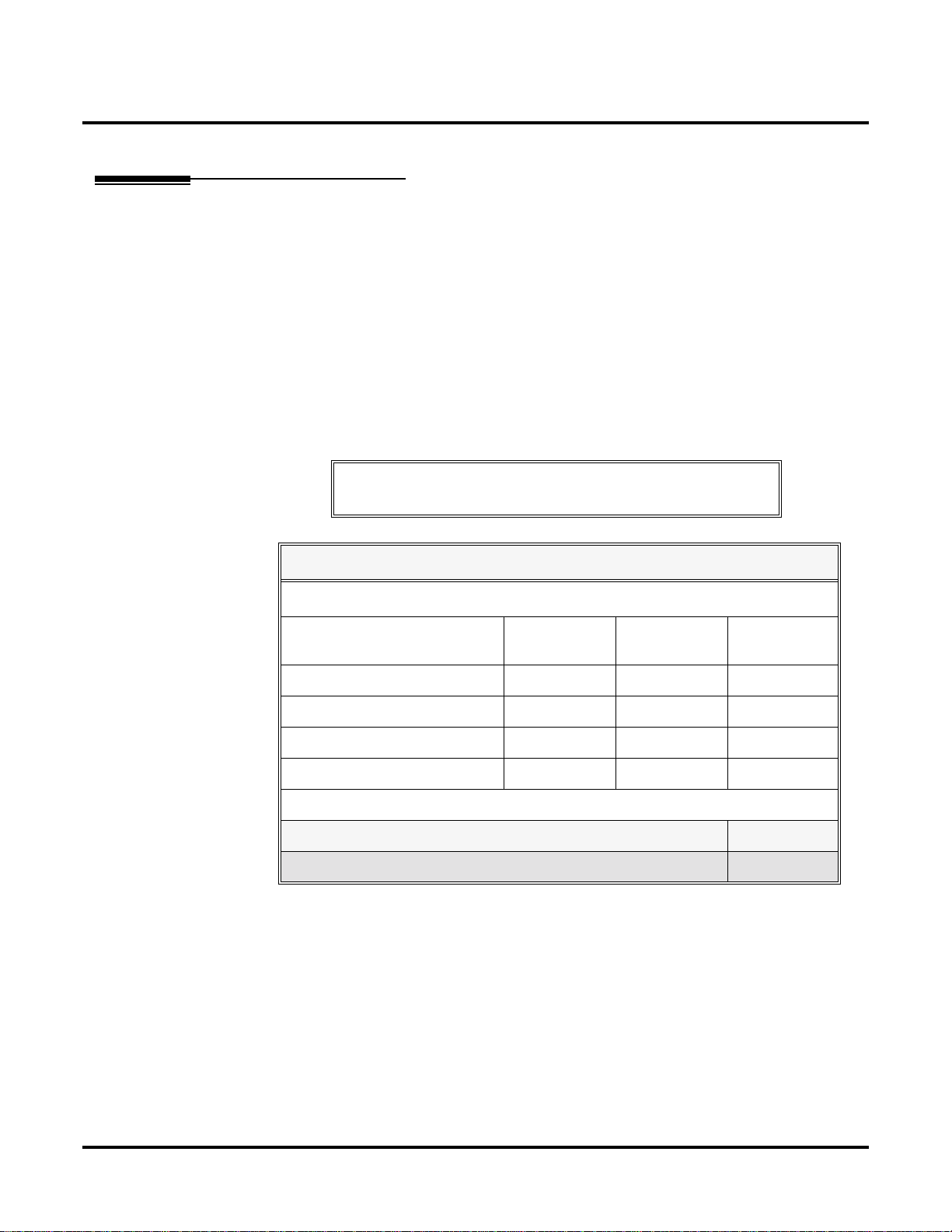
DS2000 System Load Factor Calculations
To check your system configuration:
1. Indicate the quantity for each item installed in the
2. For each item, multiply the
column.
3. Add all the values in the
4. Determine the System Load Factor capacity of the power supplies installed in your system
and enter the total in
A 4-Slot Cabinet can have only 1 power supply. An 8-Slot Cabinet can have up to 3
power supplies. You cannot have more than two 16DSTU PCBs per power supply, regardless of System Load Factor calculations.
Exceeding the System Load Factor will cause the system’s power supplies to automatically shut down.
5. Compare the entry in
than the entry in Item 2.
96 extensions maximum.
Total Load
Item
Item
Notes for U Slot Software
Qty
times the
2
2
to your entry in
Load Factor
column and enter the value in
Item
4 ◆
Qty
column.
and enter the value in the
Item
1
1
Item 1 must always be equal to or less
T otal Load
.
Chapter 1: Features
Do not operate your system if the System Load Factor total
(Item 1) exceeds the allowable value (Item 2).
DS1000/2000 Software Manual
Page 13
DS2000 System Configuration
System Load Factor Calculations
Description Load Factor Qty Total Load
16DSTU PCB 16
4ASTU PCB 8
8ASTU PCB 12
110-Button DSS Console 2
24-Button DSS Console 1
Total DSS Consoles installed cannot exceed 4.
2-OPX Module 3
Item 1: Total load for this configuration:
Item 2: If you have one power supply installed, enter 48.
If you have two power supplies installed, enter 80.
If you have three power supplies installed, enter 112.
(2 16DSTU PCBs maximum per power supply)
Note: An 8-Slot Cabinet can have up to 3 power supplies. You cannot have more than
two 16DSTU PCBs per power supply, regardless of System Load Factor calculations.
Examples of Typical DS2000 4-Slot Cabinet Maximum Configurations
Note that only the first configuration listed below (16 x 32) applies to Fixed Slot software. Refer to
the Release Notes that came with your system to find out if you have Fixed Slot software.
●
16 x 32 (16 trunks and 32 digital extensions)
Recommended for sites with no Voice Mail and high trunk usage.
●
24 x 16 (24 trunks and 16 digital extensions)
Recommended for sites with no Voice Mail and very high trunk usage.
●
8 x 16 x 16 (8 trunks, 16 digital extensions and 16 analog extensions)
Recommended for sites with Voice Mail, normal trunk usage and high analog extension usage.
●
16 x 16 x 8 (16 trunks, 16 digital extensions and 8 analog extensions)
Recommended for sites with Voice Mail, high trunk usage and high analog extension usage.
●
8 x 32 x 8 (8 trunks, 32 digital extensions and eight analog extensions)
Recommended for sites with Voice Mail, normal to low trunk usage and low analog extension
usage.
Examples of Typical DS2000 8-Slot Cabinet Maximum Configurations
●
32 x 64 (32 trunks and 64 digital extensions)
Recommended for sites with no Voice Mail and high trunk usage. This configuration requires 2
power supplies.
●
48 x 32 (48 trunks and 32 digital extensions)
Recommended for sites with no Voice Mail and very high trunk usage. This configuration
requires 1 power supply.
●
16 x 32 x 32 (16 trunks, 32 digital extensions and 32 analog extensions)
Recommended for sites with Voice Mail, normal trunk usage and high analog extension usage.
This configuration requires 2 power supplies.
DS1000/2000 Software Manual Chapter 1: Features ◆ 5
Page 14
DS2000 System Configuration
●
32 x 32 x 16 (32 trunks, 32 digital extensions and 16 analog extensions)
Recommended for sites with Voice Mail, high trunk usage and high analog extension usage.
This configuration requires 2 power supplies.
●
16 x 64 x 16 (16 trunks, 64 digital extensions and 16 analog extensions)
Recommended for sites with Voice Mail, normal to low trunk usage and low analog extension
usage. This configuration requires 3 power supplies.
DS2000 Default Setup
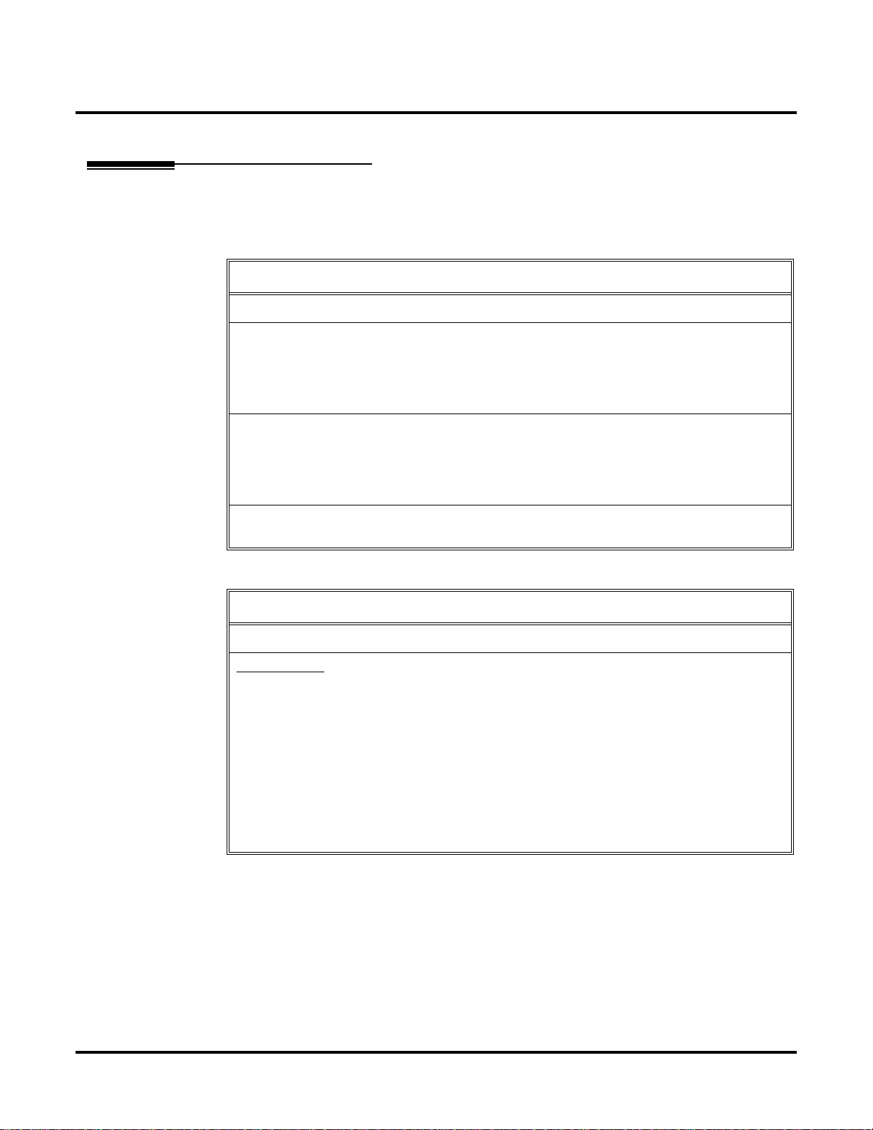
Every DS2000 system has a factory-installed default setup. The default setup determines the hardware you can install and how the system features work without reprogramming.
DS2000 4 Slot Cabinet (with Fixed Slot Software) Hardware Configuration
Following is the default PCB configuration for a 4 slot cabinet using CPU P/N 80025 with Fixed
Slot software. Although Fix ed Slot software is no longer a v ailable, you may encounter it in e xisting
installations. Note that an existing CPU P/N 80025 equipped with Fixed Slot software can be
upgraded to U Slot software. Contact your Sales Representative for the specifics.
Slot PCB Extensions
1 16DSTU 300-315
2 16DSTU 316-331
3 8 A TR U 401-408
4 8 A TR U 409-416
DS2000 4 Slot Cabinet (with U Slot Software) Hardware Configuration
Both CPU P/N 8025 and P/N 80025A can be equipped with U Slot software. When installed in a 4
slot cabinet, each version CPU will provide a unique configuration.
Configuration 1 - with CPU P/N 80025
For Software Versions 02.01.07 and Higher
●
Slot CN1 = 16DSTU PCB (extensions 300-315)
●
Slots CN2-CN4 = Undefined
●
Slots CN5-CN8 are unavailable.
●
The database is limited to 24 trunks and 40 extensions.
For Software Versions Prior to 02.01.07
Following is the default PCB configuration for a 4 slot cabinet using CPU P/N 80025 equipped with
U Slot software prior to software version 02.01.07.
Slot PCB Extensions
1 16DSTU 300-315
2 16DSTU 316-331
3 8 A TR U 401-408
4 8 A TR U 409-416
Turn to Program 9902 - Slot Assignment (page 562) for information on how to change your PCB
assignments. To swap the positions of PCBs, turn to Program 9802 - Swap Command Utility (U
Slot) (page 559).
6 ◆ Chapter 1: Features DS1000/2000 Software Manual
Page 15

DS2000 System Configuration
Configuration 2 - with CPU P/N 80025A
For Software Versions 02.01.07 and Higher
●
Slot CN1 = 16DSTU PCB (extensions 300-315)
●
Slots CN2-CN8 = Undefined
●
Slots CN5-CN8 are not provided by the 4 slot cabinet hardware (i.e., cannot physically be
installed)
●
The database provides the capability to program all 48 trunks and 96 extensions.
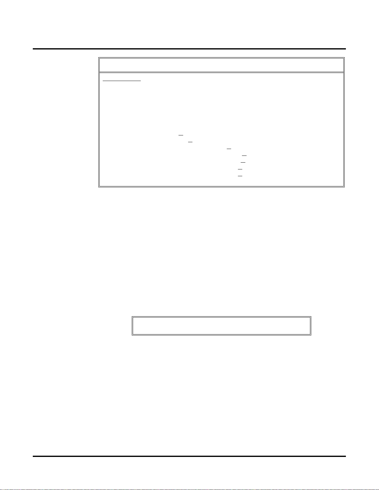
For Software Versions Prior to 02.01.07
Following is the default PCB configuration for a 4 slot cabinet using CPU P/N 80025A equipped
with U Slot software prior to software version 02.01.07. Since a 4 slot system allows only 2
16DSTU PCBs, you must reprogram this configuration.
Slot PCB Extensions
1 16DSTU 300-315
2 16DSTU 316-331
3 16DSTU 332-347
4 16DSTU 348-363
Turn to Program 9902 - Slot Assignment (page 562) for information on how to change your PCB
assignments. To swap the positions of PCBs, turn to Program 9802 - Swap Command Utility (U
Slot) (page 559).
RFI Suppressor Assemb
You can install either A series PCBs or non-A series PCBs in a 4 slot cabinet. If you install non-A
series PCBs, you must install the RFI Suppressor Assemblies as shown in your Hardware Manual.
If you install A series PCBs, you do not need to install the RFI Suppressor Assemblies on the station and trunk cables. The available PCBs are:
CPU PCB P/N 80025A and 80025
Power Supply P/N 80005A and P/N 80005
16DSTU Digital Station PCB P/N 80021A and 80021
8 ASTU 8 Port Analog Station PCB P/N 80041A and 80041
4ASTU 4 Port Analog Station PCB P/N 80040A and 80040
8ATRU 8 Port Analog Trunk PCB P/N 80011A and 80011
4ATRU 4 Port Analog Trunk PCB P/N 80010A and 80010
ly Requirements
DS1000/2000 Software Manual Chapter 1: Features ◆ 7
Page 16

DS2000 System Configuration
DS2000 8 Slot Cabinet (with U Slot Software) Hardware Configuration
For Software Versions 02.01.07 and Higher
●
Slot CN1 = 16DSTU PCB (extensions 300-315)
●
Slots CN2-CN8 = Undefined
●
The database provides the capability to program all 48 trunks and 96 extensions.
For Software Versions Prior to 02.01.07
Following is the default PCB configuration for an 8 slot cabinet with U Slot software prior to software version 2.01.07. Note that this configuration requires 3 power supplies. Refer to DS2000 Load
Factor on page 3 for more. In addition, the 8 slot cabinet does not support Fixed Slot software.
Slot PCB Extensions
1 16DSTU 300-315
2 16DSTU 316-331
3 16DSTU 332-347
4 16DSTU 348-363
5 16DSTU 364-379
6 8 A TR U 401-408
7 8 A TR U 409-416
8 8 A TR U 417-424
If you need to modify your system’s configuration, turn to
(page 562)
Slot) (page 559)
RFI Suppressor Assembly Requirements
In an 8 slot cabinet, you can only install A series PCBs. You do not need to install the RFI Suppressor Assemblies on your extension and trunk cabling. The available PCBs are:
. To swap the positions of PCBs, turn to
. You should also review the installation in your Har dware Manual before proceeding.
CPU PCB P/N 80025A
Power Supply P/N 80005A
16DSTU Digital Station PCB P/N 80021A
8 ASTU 8 Port Analog Station PCB P/N 80041A
4ASTU 4 Port Analog Station PCB P/N 80040A
8ATRU 8 Port Analog Trunk PCB P/N 80011A
4ATRU 4 Port Analog Trunk PCB P/N 80010A
Program 9902 - Slot Assignment
Program 9802 - Swap Command Utility (U
8 ◆ Chapter 1: Features DS1000/2000 Software Manual
Page 17
DS1000 System Configuration
DS1000 System Configuration
DS1000 Load Factor
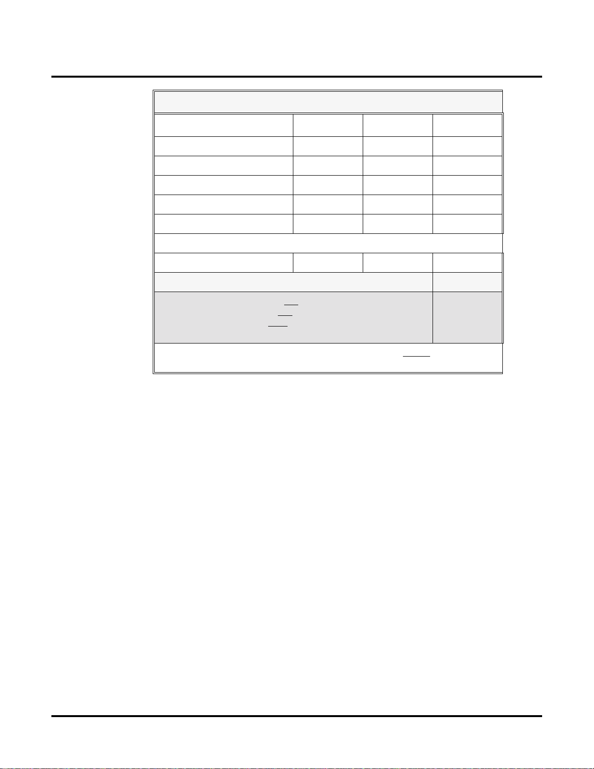
DS1000 System Load Factor Calculations
The combination of extensions, Digital Door Boxes and DSS Consoles you can connect to your
system may be limited by the System Load Factor. Use the DS1000 System Load Factor Calcula-
tions chart below to verify your system’s configuration.
To check your system configuration:
1. Indicate the quantity for each item installed in the Qty column.
2. For each item, multiply the Qty times the Load Factor and enter the value in Total Load.
3. Add all the values in the Total Load column and enter the value in Item 1.
4. Compare the entry in Item 2 to your entry in Item 1. Item 1 must always be equal to or less
than the entry in Item 2.
Do not operate your system if the System Load Factor total
(Item 1) exceeds the allowable load of 30 (Item 2).
DS1000 System Load Factor Calculations
Description Load Factor Qty Total Load
Digital Telephone and Digital
Door Box
Analog T elephone 1
Analog Door Box 0
24-Button DSS Console 1
110-Button DSS Console 2
Total DSS Consoles installed cannot exceed 4
Item 1: Total load for this configuration
Item 2: Maximum allowable load 30
1
DS1000/2000 Software Manual Chapter 1: Features ◆ 9
Page 18

DS1000 System Configuration
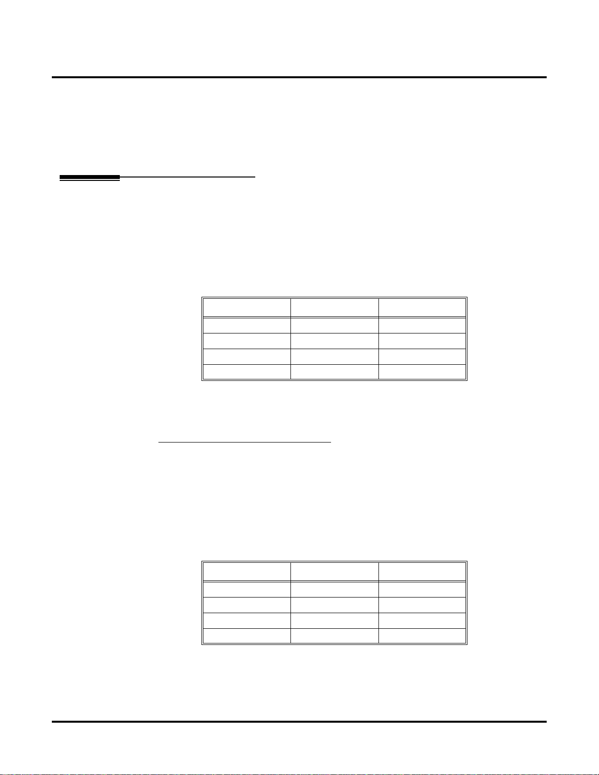
DS1000 Default Setup
Using the factory installed default configuration, your DS1000 system provides:
Trunks 3 3 6
Digital Extensions 8 8 16
Analog Extensions 4 4 8
Analog Door Boxes 1 1 2
Relays 1 1 2
Page Output 1 - 1
Music Input 1 - 1
For more on installing the DS1000 Expansion PCB, refer to the DS1000 Quick Setup Guide (P/N
80200QSET**) that came with your system.
Base Expansion Total
10 ◆ Chapter 1: Features DS1000/2000 Software Manual
Page 19

Initial System Startup
Default Feature Setup
DS2000 Fixed Slot Software (01.nn.nn)
●
All trunks are loop start DTMF
Use Program 1001 - Trunk Circuit Type (page 498) to change this assignment.
●
All extensions are 22-Button Display models.
Use Program 1801 - Extension Circuit Type (page 532) to change this assignment.
●
Trunks 1-8 ring on line keys 1-8.
Use Program 1805 - Ring Assignments (page 551) to customize ringing.
●
Extension users cannot press ICM and dial 9 for an outside line. Trunk Group Routing, Line
Dial-Up, and Direct Trunk Access are disabled.
See Central Office Calls, Placing (page 93) for more.
●
The last active Programmable Function Key on extension 300 is the Operator Call Key.
See Attendant Call Queuing (page 44) for more.
DS2000 U Slot Software and DS1000 (02.nn.nn)
●
All trunks are loop start DTMF.
Use Program 1001 - Trunk Circuit Type (page 498) to change this assignment.
●
All extensions are 22-Button Display models.
Use Program 1801 - Extension Circuit Type (page 532) to change this assignment.
●
In DS2000, trunks 1-12 ring on line keys 1-12 for extensions 300-315.
In DS1000, trunks 1-6 ring on line keys 1-6. (Trunks 4-6 require the Expansion Board.)
Use User Programmable Features (page 410) code #RAL or Program 1805 - Ring
Assignments (page 551) to customize ringing.
●
In software versions 02.01.07 and higher, extension users cannot press ICM and dial 9 for an
outside line.
See Central Office Calls, Placing (page 93) for more.
●
In software versions prior to 02.01.07, extension users can press ICM and dial 9 for an outside
line. Line Dial-Up and Direct Trunk Access are disabled.
See Central Office Calls, Placing (page 93) for more.
●
At the attendant’s e xtension (300), k ey 11 is the Night Key and key 12 is the Operator Call Key.
Pressing the Night Key puts the system in the night mode. See Night Service / Night
Ring on page 265.
Use the Operator Call Key to answer incoming Intercom calls queued at the atten-
dant’s extension. See Attendant Call Queuing on page 44.
Initial System Startup
DS1000/2000 Software Manual Chapter 1: Features ◆ 11
Page 20
Initial System Startup
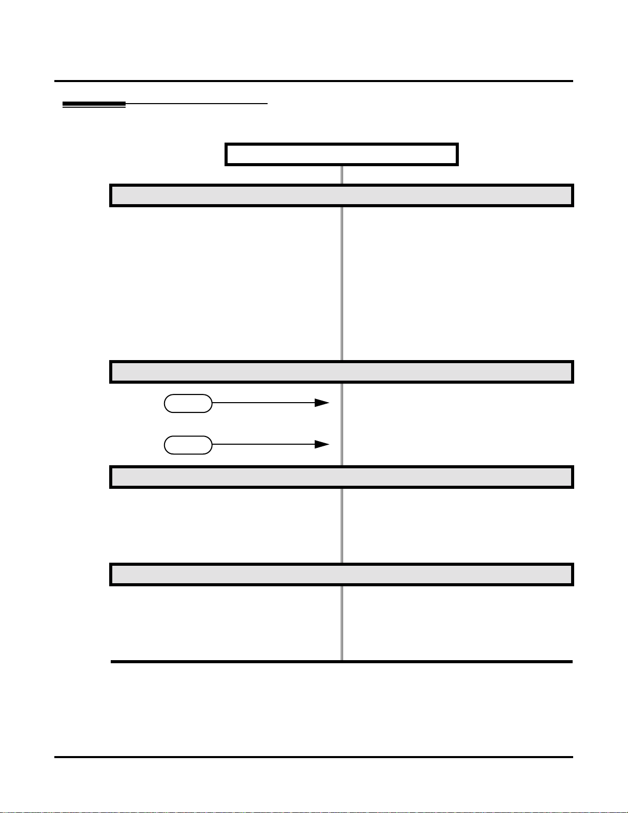
Initial Startup Programming
Step 1: Check the system defaults.
Initial Startup Programming (Page 1 of 3)
• If you have a 4 slot Fixed Slot system, refer to
DS2000 4 Slot Cabinet (with Fixed Slot Softwar e)
Hardware Configuration on page 6
• If you have a 4 slot U Slot system, refer to
DS2000 4 Slot Cabinet (with U Slot Software)
Hardware Configuration on page 6.
• If you have an 8 slot U Slot system, refer to
DS2000 8 Slot Cabinet (with U Slot Software)
Hardware Configuration on page 8.
• If you have a DS1000, refer to DS1000 Default
Setup on page 10.
• To check the feature defaults, refer to Default
Feature Setup on page 11.
Step 2: Does the current DS2000 U Slot PCB configuration meet the site requirements?
• Skip to the next step. Also skip this step if you
If yes
If no
Step 3: Enter the programming mode.
Step 4: Assign the correct circuit type to your installed trunks.
have a DS1000.
• Review Program 9902 - Slot Assignment on
page 562 and Program 9802 - Swap Command
Utility (U Slot) on page 559.
• From any display telephone:
Press ICM + #*#* + Password + HOLD.
• The default system passwords are:
Installer (level 3) = 372000
System Administrator 2 (level 2) = 9999
System Administrator 3 (level 1) = 0000
• In Pr ogr am 1001 - T runk Cir cuit Type (page 498),
enter the correct circuit type for each installed
trunk:
00 = Uninstalled
51 = Loop start DTMF
52 = Loop start DP
12 ◆ Chapter 1: Features DS1000/2000 Software Manual
Page 21
Initial System Startup
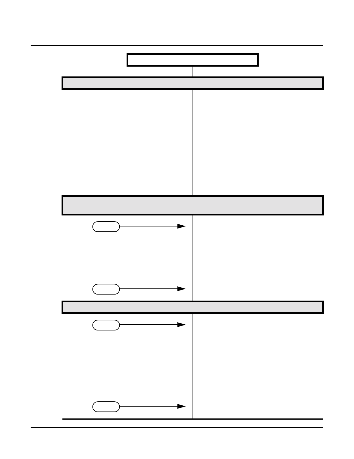
Initial Startup Programming (Page 2 of 3)
Step 5: Assign the correct circuit type to your installed extensions.
• In Program 1801 - Extension Circuit Type
(page 532), enter the correct circuit type for each
installed extension:
00 = Uninstalled
01 = 22-Button Standard
02 = 22-Button Display
06 = 34-Button Display
09 = 34-Button Super Display
10 = Digital Door Box [1]
15 = Analog station
21 = 2OPX (DS2000 Only)
• All keysets default to type 02 (22-Button Display). If you don’t change the circuit type for 34Button and 34-Button Super Display telephones,
the bottom two rows of Programmable Function
Keys will be unassigned (i.e., not functioning).
Step 6: By default, each extension has full access to each trunk. Do you want to change
this assignment?
• For each extension in Program 1803 - Extension
If yes
If no
Step 7: Do you want to change the way extensions ring for incoming trunk calls?
If yes
Line Access Assignments (page 546), assign the
access options for each trunk. The options are:
0 = No access
1 = Incoming only
2 = Outgoing only
3 = Full access
• Use Pr ogr am 9801 - Copy Command (page 557),
to simplify your programming.
• In Program 1803 - Extension Line Access Assign-
ments (page 546), make no changes from the
default assignments.
• For each extension in Program 1805 - Ring
Assignments (page 551), assign ringing for each
trunk. The options are:
1 = Lamp only (day and night)
2 = Ringing day and night
3 = Night Ring only, lamp during the day
4 = Delay ring day and night
• Use Pr ogr am 9801 - Copy Command (page 557),
to simplify your programming.
• The system attendant (extension 300) can put
these trunks in the night mode by pressing their
preassigned Night Key (key 11).
• For each extension in Program 1805 - Ring
If no
DS1000/2000 Software Manual Chapter 1: Features ◆ 13
Assignments (page 551), make no changes from
the default assignments.
Page 22
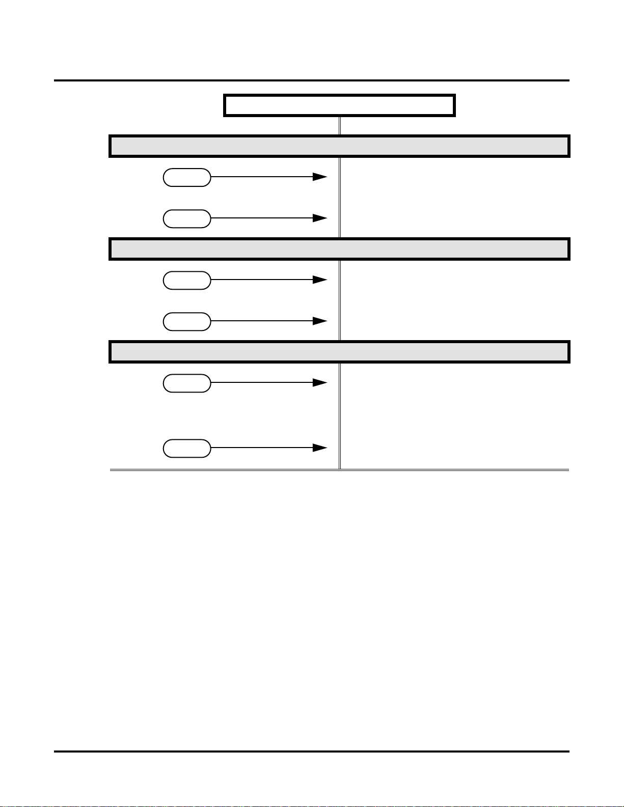
Initial System Startup
Step 8: Does your system have Voice Mail?
If yes
If no
Step 9: Do you want to change the default system passwords?
If yes
If no
Step 10: Do you want to return the system to its factory installed (default) programming?
Initial Startup Programming (Page 3 of 3)
• Turn to Voice Mail on page 414 and review the
required Voice Mail programming.
• Go to the next step.
• In Program 9905 - Password (page 566), change
the passwords from their default settings.
• In Program 9905 - Password (page 566), do not
change the passwords from their default settings.
If yes
If no
• In Program 9999 - System Initialization
(page 571), reinstate the factory installed programming. This erases all your programming
and returns the system to its initial default settings.
• In Program 9999 - System Initialization
(page 571), do not reinstate the factory installed
programming.
14 ◆ Chapter 1: Features DS1000/2000 Software Manual
Page 23

Charts and Illustrations
Charts and Illustrations
Table 1: Dial Codes (by Feature)
For this feature Dial this code When you are
Barge In (Intrusion) 4
Call Forwarding
ICM + *32 + Extension or 0 (for the
ICM + *34 + Extension or 0 (for the
ICM + *36 + Extension or 0 (for the
ICM + *37 + 2 (all calls) or 8 (outside
Call Waiting / Camp-On
Central Office Calls, Placing
ICM + #9
ICM + Trunk number (e.g., 01) Using Direct Trunk Access to place an
Barging-In on a co-worker’s call
ICM + *30
Canceling Call Forwarding at an
extension
Enabling Call Forwarding Busy/No
operator)
Answer
Enabling Call Forwarding All Calls
operator)
Enabling Call Forwarding No Answer
operator)
Setting up Personal Answering
calls)
+ Do not hang up
2
2 + Hang up
Leaving a Callback for a co-worker
Machine Emulation
Camping-On to a co-worker
+ Trunk number (e.g., 01) Using Line Dial-Up to place an out-
side call
outside call
ICM + 9 or 90-98 Accessing a Trunk Group to place an
outside call
Dial Number Preview #
Directed Call Pickup
Forced T runk Disconnect #
Group Call Pickup
Hold
Intercom
Meet-Me Conference
Monitor / Silent Monitor 6
Night Service / Night Ring
+ #4 + Trunk number (e.g., 01) Picking up an outside call on System
ICM
ICM
ICM
ICM
+ Extension (e.g., 301) Placing an Intercom call to a
+ #11 or # 12 Setting up or joining a Meet-Me Con-
ICM
+ UNA code (01-04) Answering a call ringing UNA at
##
Previewing a number before dialing
+ # # Intercepting a call ringing a
co-worker’s extension
Using Forced Trunk Disconnect to
disconnect a busy outside line
+ * # Answering a call ringing a phone in
your Pickup Group
Hold at a co-worker’s extension
co-worker
ference
Setting up Monitor after calling a busy
co-worker
night
DS1000/2000 Software Manual Chapter 1: Features ◆ 15
Page 24

Charts and Illustrations
Table 1: Dial Codes (by Feature)
For this feature Dial this code When you are
Paging
Park
Removing Trunks and Extensions
From Service
+ Page zone (1-7 or 0 for All Call) Making an internal Paging announce-
*1
+ ** + System Park Orbit (60-69) Parking or retrieveing a call from Sys-
ICM
ICM + ** + Extension (e.g., 301)
+ #40 + Extension (e.g., 301) or
ICM
trunk (e.g., 401) + 4 (to return) or 6
(to remove)
Selectable Display Messaging ICM + *38 + Message (00-16) + Hold
+ Add additional digits + Hold
Speed Dial
+ ## + System bin (200-299) or
ICM
Personal bin (701-720)
Transfer
ICM + Extension (e.g., 301) + MW
Trunk (Line) Queuing / Trunk Call-
back
Voice Mail
+ Extension (e.g., 301)
ICM
2
+ MW
ICM
ment
tem Park Orbit
Using Personal Park to Park or retrie ve
a call at a co-workers extension
Removing or returning an extension or
trunk to service
Enabling a Selectable Display Message
Dialing a System or Personal Speed
Dial number
Transferring a call to a co-worker’s
extension
Transferring a call to a co-worker’s
mailbox
Queuing or leaving a Callback for a
busy trunk
Calling your mailbox
ICM + Extension (e.g., 301) + MW
ICM + *37 + 2 (all calls) or 8 (outside
calls)
ICM + *30 Canceling Personal Answering
Voice Over 9
Transferring a call to a co-worker’s
mailbox
Setting up Personal Answering
Machine Emulation
Machine Emulation
Initiating a Voice Over to a busy exten-
sion (after hearing busy/ring tone)
16 ◆ Chapter 1: Features DS1000/2000 Software Manual
Page 25
Charts and Illustrations
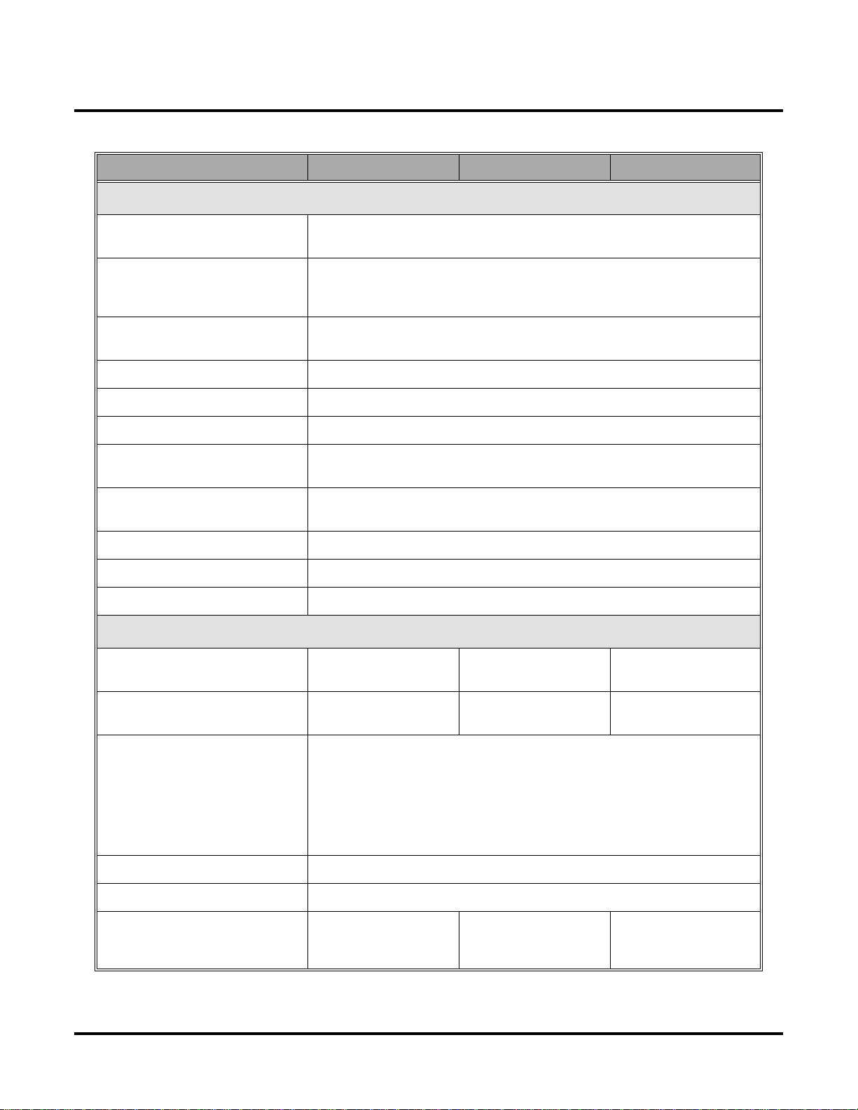
Table 2: System Number Plan/Capacities (Page 1 of 3)
DS1000 DS2000 4-Slot DS2000 8-Slot
System Options
• Classes of Service 1-15
(COS 1 normally reserved for attendants)
• Conference 32 simultaneous users in Conference (total of all Conferences system-wide)
8 simultaneous Conferences maximum
8 parties maximum in any one Conference
• Extension Hunting (ACD/
UCD) Master Numbers
• Extension Hunting Groups 8 (1-8)
• Group Call Pickup Groups 8 (1-8, 0 = unassigned)
• Privacy Release Groups 16 (1-16, 0 = unassigned)
• Speed Dial, Personal 20 bins at each extension (701-720)
See
Speed Dial (page 332)
• Speed Dial. System
See
Speed Dial (page 332)
• Tenant Groups 1
• Timeslots Non-blocking
• Toll Restriction Levels 7 (1-7, 0 = no restriction)
Trunks
• Direct Trunk Access Codes 401-406 401-416 (Fixed Slot)
• Line Dial Up Codes #901-#906 #901-#916 (Fixed Slot)
10 (20-29), 100 (200-299), 1000 (2000-2999)
for additional information on Speed Dial capacities.
for additional information on Speed Dial capacities.
401-424 (U Slot)
#901-#924 (U Slot)
8
401-448
#901-#948
• Ring Groups 8 (1-8)
0 = No assignment
Ring Group master numbers can be 100-299, 332-400, or 417-899. They can-
not be in the extension (300-395 in DS2000 or 300-325 in DS1000) or trunk
(401-448 in DS2000 or 401-406 in DS1000) number range. By default, the
systems uses codes beginning with 0 for operator access and 9 for trunk/trunk
group access.
• Trunk Group Access Codes 90-98
• Trunk Groups 9 (0-8)
• Trunk Ports 6 (1-6)
Trunks 4-6 require the
Expansion Board.
DS1000/2000 Software Manual Chapter 1: Features ◆ 17
16 (1-16) (Fixed Slot)
24 (1-24) (U Slot)
48 (1-48)
Page 26
Charts and Illustrations
Table 2: System Number Plan/Capacities (Page 2 of 3)
Extensions
DS1000 DS2000 4-Slot DS2000 8-Slot
• Attendant (Operator) Access
Number
• Attendants 4
• Digital Door Boxes
• Analog Door Boxes 2
• DSS Consoles 4
• Telephone Extension Numbers 300-325 (which
• Telephone Port Numbers 26 (1-26) 32 (1-32) (Fixed Slot)
• Total Number of Station
Devices
Each Digital Door Box uses one digital station port. The System Load Factor may
limit the total number you can install. See
DS1000 Load Factor on page 9
2nd Analog Door Box
requires Expansion PCB
The System Load Factor may limit the total number that you can install.
DS2000 Load Factor on page 3
includes digital exten-
sions 300-315, analog
extensions 31-323, and
Analog Door Boxes
324 and 325)
26 (which includes dig-
ital extensions 300-315,
analog extensions 31-
323, and Analog Door
Boxes 324 and 325)
0 (single operator)
01-04 (multiple operators)
DS2000 Load Factor on page 3
. Not available in DS2000 Fixed Slot software.
and
DS1000 Load Factor on page 9
32 (300-331) (Fixed
Slot)
40 (300-339) (U Slot)
40 (1-40) (U Slot)
32 (Fixed Slot) (may be
limited by load factor)
40 (U Slot) (may be
limited by load factor)
and
0
See
.
96 (300-395)
96 (1-96)
96 (may be limited by
load factor)
• UCD Hunting Master Numbers
Master numbers can be from 100-899, excluding those extension numbers
used by extensions and trunks. By default, the systems uses codes beginning
with 0 for operator access and 9 for trunk/trunk group access.
• Voice Mail Master Numbers 1
Master numbers can be from 100-899, excluding those extension numbers
used by extensions and trunks. By default, the systems uses codes beginning
with 0 for operator access and 9 for trunk/trunk group access.
• Voice Mail Ports Limited by available analog ports.
Paging and Park
• Page Zones (Internal) 7 zones (1-7) and All Call (0)
• Page Zone (External) All Call and zone 1
broadcast from Audio
jack (AUDIO)
18 ◆ Chapter 1: Features DS1000/2000 Software Manual
8 (1-8)
All Call and zone 1 broadcast from the CPRU
External Page port
Page 27
Charts and Illustrations
Table 2: System Number Plan/Capacities (Page 3 of 3)
DS1000 DS2000 4-Slot DS2000 8-Slot
• Page Relays One set in each Analog
Door Box jack
(DOOR1 and DOOR2)
• Park Orbits 10 (60-69)
Orbits 68 and 69 have extended (5 min.) timers
Passwords
• System Administrator 1
(Level 1)
• System Administrator 2
(Level 2)
• Installer (Level 3) 372000
0000
9999
One set on CPRU
DS1000/2000 Software Manual Chapter 1: Features ◆ 19
Page 28

Charts and Illustrations
80000 - 21A
CLEAR
CHECK
LINE 1 LINE 2 LINE 3 LINE 4 LINE 5 LINE 6
LINE 7 LINE 8
BIN 1 BIN 2 BIN 3 BIN 4 BIN 5
BIN 6 BIN 7 BIN 8 BIN 9 BIN 10
FIXED
LOOP 0
ABC DEF
FIXED
LOOP 0
AUTO
TIMER
MW ICM
ALL
PAGE
1 2 3
GHI JKL MNOMNO
FLASH DND
4 5 6
PQRS TUV
WXYZ
DIAL MIC
7 8 9
OPER
LND SPK
0
VOL
CONF
HOLD
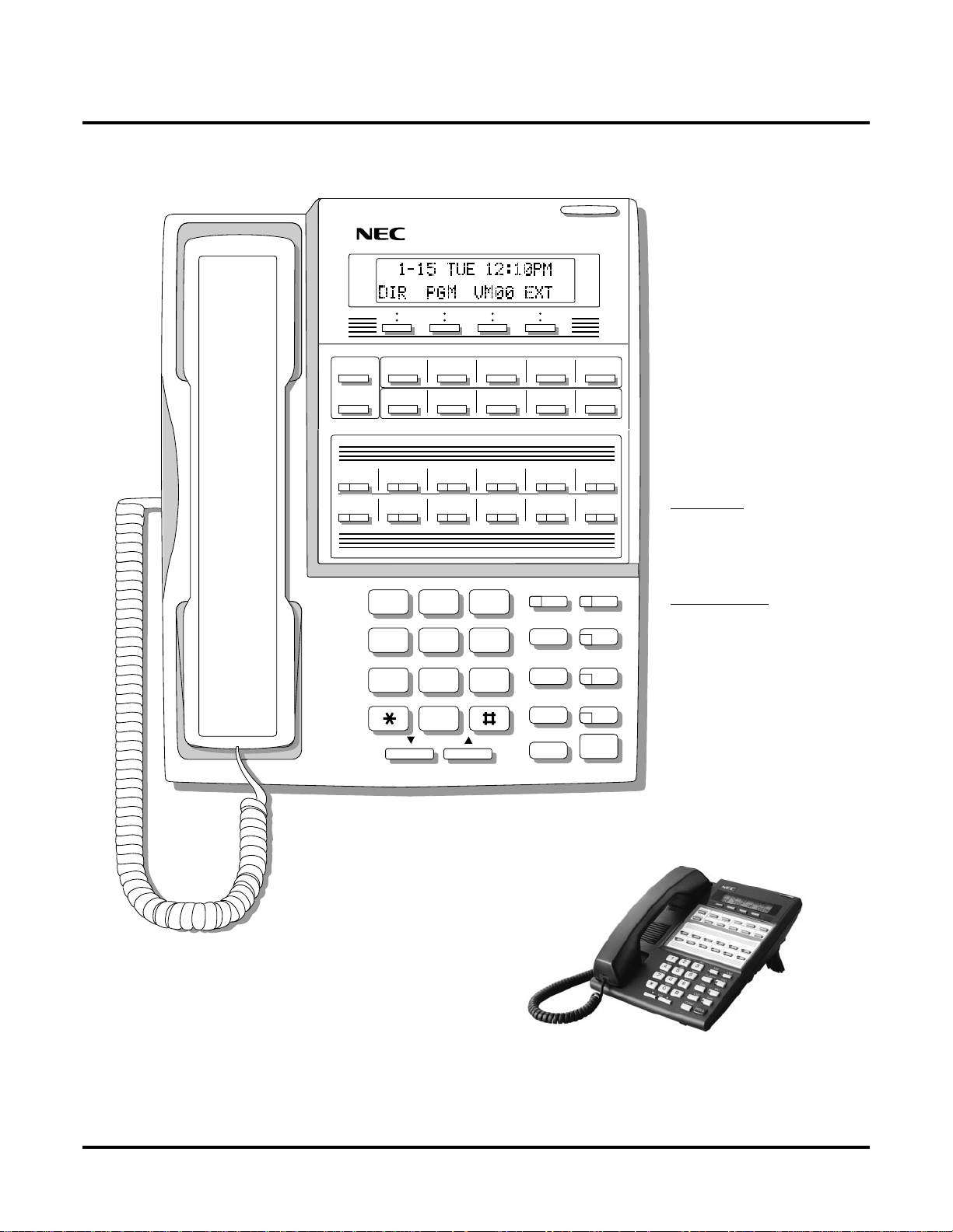
For Attendants:
Key 11=Night Key
Key 12=Operator Call Key
Figure 1: 22-Button Display Telephone (Fixed Slot)
20 ◆ Chapter 1: Features DS1000/2000 Software Manual
Page 29
80000 -62A
Charts and Illustrations
CLEAR
CHECK
LINE 1 LINE 2 LINE 3 LINE 4 LINE 5 LINE 6
LINE 7 LINE 8
BIN 1 BIN 2 BIN 3 BIN 4 BIN 5
BIN 6 BIN 7 BIN 8 BIN 9 BIN 10
LINE 9 LINE 10 LINE 11 LINE 12
ABC DEF
MW ICM
1 2 3
GHI JKL MNOMNO
FLASH DND
4 5 6
PQRS TUV
WXYZ
DIAL MIC
7 8 9
OPER
LND SPK
0
VOL
CONF
HOLD
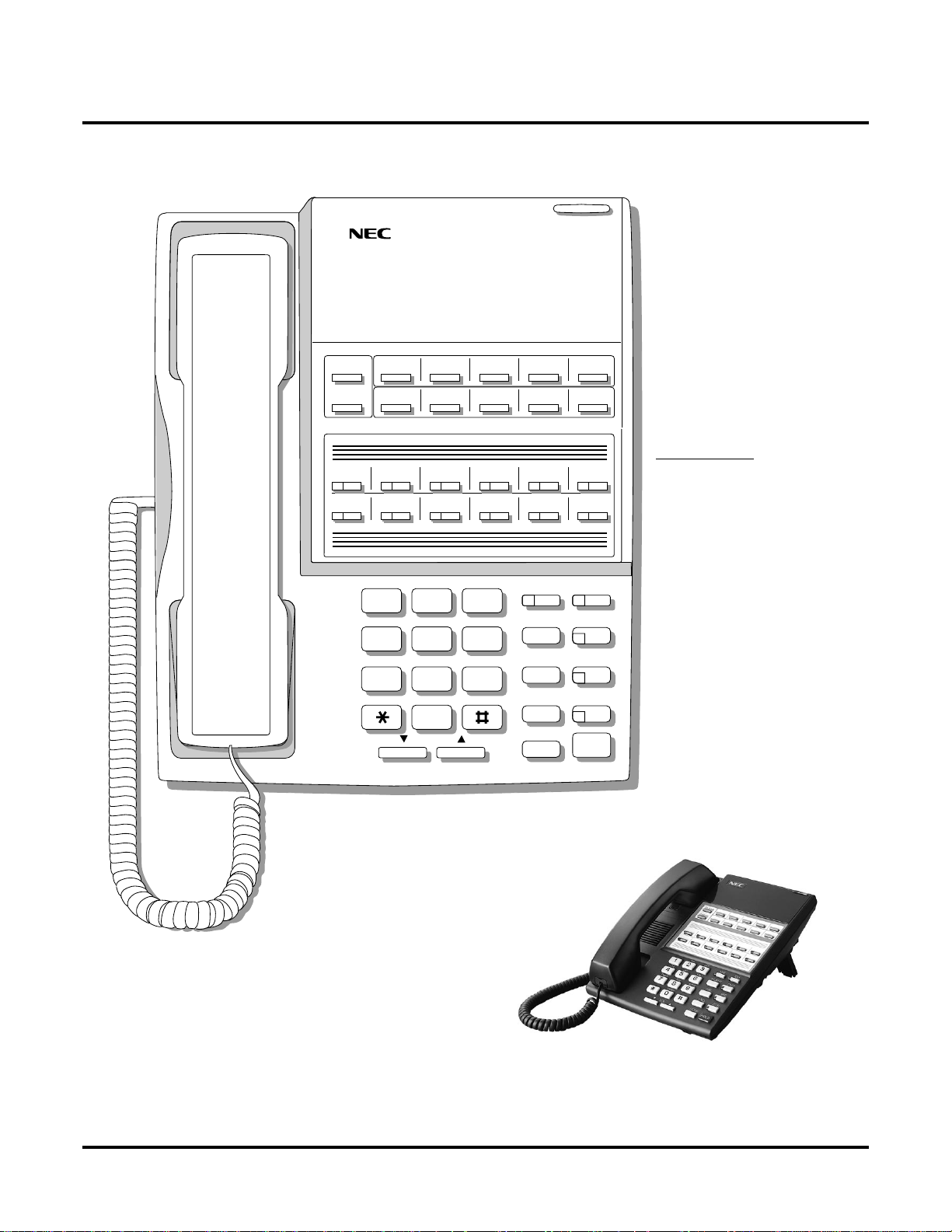
In DS1000:
Keys 7-12 are
undefined.
For Attendants:
Key 11=Night Key
Key 12=Operator Call Key
In DS2000 software version 02.01.07 and higher,
Programmable Function Keys are undefined for all
extensions above 315.
Figure 2: 22-Button Display Telephone (U Slot and DS1000)
DS1000/2000 Software Manual Chapter 1: Features ◆ 21
Page 30
Charts and Illustrations
80000 - 22A
CLEAR
CHECK
LINE 1 LINE 2 LINE 3 LINE 4 LINE 5 LINE 6
LINE 7 LINE 8
FIXED
LOOP 0
FIXED
LOOP 0
AUTO
TIMER
ALL
PAGE
For Attendants:
Key 11=Night Key
Key 12=Operator Call Key
ABC DEF
1 2 3
GHI JKL MNOMNO
4 5 6
PQRS TUV
WXYZ
7 8 9
OPER
0
VOL
MW ICM
FLASH DND
DIAL MIC
LND SPKR
CONF
HOLD
Figure 3: 22-Button Standard Telephone (Fixed Slot)
22 ◆ Chapter 1: Features DS1000/2000 Software Manual
Page 31

80000 - 63A
Charts and Illustrations
CLEAR
CHECK
LINE 1 LINE 2 LINE 3 LINE 4 LINE 5 LINE 6
LINE 7 LINE 8
LINE 9 LINE 10 LINE 11 LINE 12
In DS1000:
Keys 7-12 are
undefined.
ABC DEF
1 2 3
GHI JKL MNOMNO
4 5 6
PQRS TUV
WXYZ
7 8 9
OPER
0
VOL
In DS2000 software version 02.01.07 and higher,
Programmable Function Keys are undefined for all
extensions above 315.
MW ICM
FLASH DND
DIAL MIC
LND SPKR
CONF
HOLD
For Attendants:
Key 11=Night Key
Key 12=Operator Call Key
Figure 4: 22-Button Standard Telephone (U Slot and DS1000)
DS1000/2000 Software Manual Chapter 1: Features ◆ 23
Page 32

Charts and Illustrations
80000 - 10C
CLEAR
CHECK
LINE 1 LINE 2 LINE 3 LINE 4 LINE 5 LINE 6
LINE 7 LINE 8
BIN 1 BIN 2 BIN 3 BIN 4 BIN 5
BIN 6 BIN 7 BIN 8 BIN 9 BIN 10
FIXED
LOOP 0
ABC DEF
FIXED
LOOP 0
AUTO
TIMER
MW ICM
ALL
PAGE
1 2 3
GHI JKL MNOMNO
FLASH DND
4 5 6
PQRS TUV
WXYZ
DIAL MIC
7 8 9
OPER
LND SPK
0
VOL
CONF
HOLD
These keys are
undefined
For Attendants:
Key 11=Night Key
Key 24=Operator Call Key
Figure 5: 34-Button Display Telephone (Fixed Slot)
24 ◆ Chapter 1: Features DS1000/2000 Software Manual
Page 33

80000 - 64A
Charts and Illustrations
CLEAR
CHECK
LINE 1 LINE 2 LINE 3 LINE 4 LINE 5 LINE 6
LINE 7 LINE 8
BIN 1 BIN 2 BIN 3 BIN 4 BIN 5
BIN 6 BIN 7 BIN 8 BIN 9 BIN 10
LINE 9 LINE 10 LINE 11 LINE 12
ABC DEF
MW ICM
1 2 3
GHI JKL MNOMNO
FLASH DND
4 5 6
PQRS TUV
WXYZ
DIAL MIC
7 8 9
OPER
LND SPK
0
VOL
CONF
HOLD
For Attendants:
Key 11=Night Key
Key 24=Operator Call Key
Keys 13-24 are undefined
for non-attendants in DS2000.
Keys 7-24 are undefined for
non-attendants in DS1000.
In DS2000 software version 02.01.07 and higher,
Programmable Function Keys are undefined for all
extensions above 315.
Figure 6: 34-Button Display Telephone (U Slot and DS1000)
DS1000/2000 Software Manual Chapter 1: Features ◆ 25
Page 34

Charts and Illustrations
80000 - 23A
CHECK CLEAR
LINE 1 LINE 2 LINE 3 LINE 4 LINE 5 LINE 6
LINE 7 LINE 8
FIXED
LOOP 0
FIXED
LOOP 0
AUTO
TIMER
ALL
PAGE
These keys are
undefined
ABC DEF
1 2 3
GHI JKL MNO
4 5 6
PQRS TUV
WXYZ
7 8 9
OPER
0
VOL
MW ICM
FLASH DND
DIAL MIC
LND SPKR
CONF
HOLD
For Attendants:
Key 11=Night Key
Key 24=Operator Call Key
Figure 7: 34-Button Super Display Telephone (Fixed Slot)
26 ◆ Chapter 1: Features DS1000/2000 Software Manual
Page 35

80000 - 65A
Charts and Illustrations
CHECK CLEAR
LINE 1 LINE 2 LINE 3 LINE 4 LINE 5 LINE 6
LINE 7 LINE 8
LINE 9 LINE 10 LINE 11 LINE 12
ABC DEF
MW ICM
1 2 3
GHI JKL MNO
FLASH DND
4 5 6
PQRS TUV
WXYZ
DIAL MIC
7 8 9
OPER
LND SPKR
0
VOL
CONF
HOLD
For Attendants:
Key 11=Night Key
Key 24=Operator Call Key
Keys 13-24 are undefined
for non-attendants in DS2000.
Keys 7-24 are undefined for
non-attendants in DS1000.
In DS2000 software version 02.01.07 and higher,
Programmable Function Keys are undefined for all
extensions above 315.
Figure 8: 34-Button Super Display Telephone (U Slot and DS1000)
DS1000/2000 Software Manual Chapter 1: Features ◆ 27
Page 36

Charts and Illustrations
80000 - 25
300 312
301 313
302 314
303 315
304 316
305 317
306 318
307 319
308 320
309 321
310 322
311 323
Figure 9: 24-Button DSS Console
28 ◆ Chapter 1: Features DS1000/2000 Software Manual
Page 37

80000 - 24
Charts and Illustrations
300 301 302 303 304 305 306 307 308 309
310 311 312 313 314 315 316 317 318 319
320 321 322 323 324 325 326 327 328 329
330 331 LINE 1 LINE 2 LINE 3 LINE 4 LINE 5 LINE 6 LINE 7 LINE 8
LINE 9 LINE 10 LINE 11 LINE 12 LINE 13 LINE 14 LINE 15 LINE 16 200 201
202 203 204 205 206 207 208 209 701 702
703 704 705 706 707 708 709 710 711 712
713 714 715 716 717 718 719 720 PG 0 PG 1
PK 0 PK 1
These keys are
undefined
Figure 10: 110-Button DSS Console (Fixed Slot)
DS1000/2000 Software Manual Chapter 1: Features ◆ 29
Page 38

Charts and Illustrations
80000 - 66
300 301 302 303 304 305 306 307 308 309
310 311 312 313 314 315 316 317 318 319
320 321 322 323 324 325 326 327 328 329
330 331 332 333 334 335 336 337 338 339
340 341 342 343 344 345 346 347 348 349
350 351 352 353 354 355 356 357 358 359
360 361 362 363 364 365 366 367 368 369
These keys are
undefined
370 371 372 373 374 375 376 377 378 379
PAGE 1 PAGE 2 PAGE 3
PARK 0 PARK 1 PARK 2 PARK 3 PARK 4 PARK 5 PARK 6 PARK 7 PARK 8 NIGHT
PAGE
ALL
Figure 11: 110-Button DSS Console (U Slot)
30 ◆ Chapter 1: Features DS1000/2000 Software Manual
Page 39

80200 - 38
Charts and Illustrations
300 301 302 303 304 305 306 307 308 309
Hotlines
to
Extensions
310 311 312 313 314 315 316 317 318 319
320 321 322 323 324 325
PAGE 1 PAGE 2 PAGE 3
PARK 0 PARK 1 PARK 2 PARK 3 PARK 4 PARK 5 PARK 6 PARK 7 PARK 8 NIGHT
Note: Blank keys are undefined.
PAGE
ALL
Figure 12: 110-Button DSS Console (DS1000)
DS1000/2000 Software Manual Chapter 1: Features ◆ 31
Page 40

2-OPX Module
2-OPX Module
Description
DS2000 Fixed Slot
DS2000 U Slot
DS1000 Not available.
Available. See see Off-Premise Extensions / On-Premise SLT Extensions on
page 274.
32 ◆ Chapter 1: Features DS1000/2000 Software Manual
Page 41

2500 Sets / Single Line Telephones
2500 Sets / Single Line Telephones
Description
DS2000 Fixed Slot
DS2000 U Slot
DS1000
Available. Refer to Off-Premise Extensions / On-Premise SLT Extensions on
page 274 for more.
DS1000/2000 Software Manual Chapter 1: Features ◆ 33
Page 42

Account Codes
Account Codes
Description
DS2000 Fixed Slot Not available.
DS2000 U Slot
DS1000
Use Account Codes to categorize and/or restrict outside calls.
Account Codes are user-dialed codes that help categorize and/or restrict trunk calls. Account
Codes are from 2-10 digits long, using any combination of the digits 0-9. There are three types of
Account Codes:
● Optional (Unforced Account Codes)
● Forced Account Codes
● V erified Account Codes
Optional (Unforced) Account Codes
Optional Account Codes allow a keyset extension user to enter an Account Code while placing a
trunk call or any time while on a call. This type of Account Code is optional: the system does not
require the user to enter it. If the keyset user is already talking on a trunk call, their conversation
continues uninterrupted while they enter an Account Code.
Available. Requires software version 02.01.07 or higher.
Single line telephone users can only enter an Account Code while placing their trunk call.
Forced Account Codes
Forced Account Codes require an extension user to enter an Account Code every time they place a
trunk call. If the user doesn’t enter the code, the system prevents the call. The system can require
Forced Account Codes for all trunk calls, or just for toll calls (as determined by Toll Restriction
programming). Note that Forced Account Codes do not pertain to incoming calls.
Verified Account Codes
With Verified Account Codes, the system compares the Account Code the user dials with a list of
codes programmed into the Verified Account Code Table. If the Account Code is in the table, the
call goes through (provided it is not prevented by an extension’s Toll Restriction programming). If
the code is not in the table, the system prevents the call. Verified Account Codes, if enabled, apply
only to Forced Account Codes.
Using Account Codes and Speed Dial
To simplify Account Code operation, Personal and System Speed Dial bins can contain Account
Codes. Keep the following in mind when using Speed Dial and Account Codes:
●
The Account Code can be either the first or last entry in the bin, and must be preceded and followed by the # character. For example, the Account Code 1234 must be entered as #1234#.
●
The
Program 0201 - # Key to Enter Account Codes (page 447)
tem programming. In addition, the
(2.01.07 or higher) (page 446)
●
The Speed Dial bin can contain an Account Code followed by an outside number, or just the
Program 0201 - Enable Account Codes in Speed Dial
option must also be enabled.
Account Code. The Account Code must be preceded and followed by a # entry. If the bin
contains just the Account Code, the user must be sure to press the bin key before dialing the
outside number.
option must be enabled in sys-
34 ◆ Chapter 1: Features DS1000/2000 Software Manual
Page 43

Account Codes
●
If the system has Verified Account Codes enabled, the Account Code entered in the Speed Dial
bin must match an entry in the Verified Account Code Table.
●
If the Speed Dial bin does not contain an Account Code, the user must enter the Account Code
manually. If Forced Account Codes are enabled, the system requires the user to enter the
Account Code before it outdials the stored Speed Dial number.
●
An extension user can preselect a trunk for a Speed Dial call.
Using Account Codes with Last Number Redial and Save
Last Number Redial and Save do not store Account Codes. This means that the user must manually
enter an Account Code to ha v e it included with a call dialed using Last Number Redial and Sa v e. If
Forced Account Codes are enabled, the system requires
outdials the stored number saved by Last Number Redial or Save.
An extension user can preselect a trunk for a Last Number Redial or Save call.
Account Codes and Emergency Calls
Account Codes are never enforced for emergency (911 and 1+911) calls.
Conditions
Do not use Account Codes that begin with 911 or 1911.
Default Setting
Account Codes disabled.
the user to enter the Account Code before it
DS1000/2000 Software Manual Chapter 1: Features ◆ 35
Page 44

Account Codes
Programming Guide
Step 1: Should users be able to store Account Codes in Speed Dial bins?
Step 2: While on an outside call, should an extension user be able to dial # to enter an
Account Code?
If yes
If no
If yes
Step-by-step guide for setting up
Account Codes (Page 1 of 2)
• In Program 0201 - Enable Account Codes in
Speed Dial (2.01.07 or higher) (page 446), enter
Y.
• In Program 0201 - Enable Account Codes in
Speed Dial (2.01.07 or higher) (page 446), enter
N. Any Account Codes stored in Speed Dial bins
dial out as part of the stored number.
• In Program 0201 - # Key to Enter Account Codes
(page 447), enter Y.
• In Program 0201 - # Key to Enter Account Codes
If no
Step 3: Should Account Code entries be hidden (i.e., replaced by * characters) on each tele-
phone’s display?
If yes
If no
Step 4: Should a keyset have an Account Code key to simplify entering Account Codes?
If yes
If no
(page 447), enter N.
• In Program 0201 - View Account Codes
(page 447), enter N.
• In Program 0201 - View Account Codes
(page 447), enter Y.
• In Program 1701 - Programmable Function Key
Assignments (page 517), enter 26 to assign a key
as an Account Code key.
• In Program 1701 - Programmable Function Key
Assignments (page 517), do not assign a key with
code 26.
36 ◆ Chapter 1: Features DS1000/2000 Software Manual
Page 45

Account Codes
Step-by-step guide for setting up
Account Codes (Page 2 of 2)
Step 5: Should an extension have Forced Account Codes (i.e., be required to enter an
Account Code while placing a call)?
• In Program 0101 - Forced Account Codes
If yes
If no
Step 6: Should an extension have Forced Account Codes just for long distance (toll) calls?
If yes
(page 443), enter Y.
• Program 1801 - Extension Class of Service
Assignment (page 533), assign Class of Service to
extensions.
• In Program 0101 - Forced Account Codes
(page 443), enter N.
• Program 1801 - Extension Class of Service
Assignment (page 533), assign Class of Service to
extensions.
• In Pr ogr am 0101 - Forced Account Codes for Toll
Calls Only (page 443), enter Y.
• In Program 0201 - Account Code Toll Level
(page 447), enter the toll level (0-7) the system
will use to determine toll calls. See Forced
Account Codes Programming on page 38 for
more on setting this up.
• Program 1801 - Extension Class of Service
Assignment (page 533), assign Class of Service to
extensions.
• In Pr ogr am 0101 - Forced Account Codes for Toll
If no
Step 7: Should an extension have Verified Account Codes (i.e., be required to enter an
Account Code from the Verified Account Codes Table while placing a call)?
If yes
If no
Calls Only (page 443), enter N.
• Program 1801 - Extension Class of Service
Assignment (page 533), assign Class of Service to
extensions.
• In Program 0101 - Verify Account Codes
(page 443), enter Y.
• In Program 1201 - Verified Account Codes Table
(page 515), enter codes into the Verified Account
Codes table.
• In Program 1801 - Extension Class of Service
Assignment (page 533), assign Class of Service to
extensions.
• In Program 0101 - Verify Account Codes
(page 443), enter N.
• Program 1801 - Extension Class of Service
Assignment (page 533), assign Class of Service to
extensions.
DS1000/2000 Software Manual Chapter 1: Features ◆ 37
Page 46

Account Codes
Programming List
General Account Codes Programming
Program 0201 - Enable Account Codes in Speed Dial (2.01.07 or higher) (page 446)
Program 0201 - # Key to Enter Account Codes (page 447)
Program 0201 - View Account Codes (page 447)
Program 1701 - Programmable Function Key Assignments (page 517)
Enable (Y) this option if users should be able to store Account Codes in Speed Dial bins. This
causes the stored Account Code to properly display in the SMDR report Account column. If
you disable (N) this option, Account Codes stored in Speed Dial bins dial out as part of the
stored number and display in the SMDR report Number Dialed column. They will not display
in the Account column. This option is disabled by default.
Use this option to enable (Y) an extension user to dial # to enter an Account Code while on an
outside call. If disabled (N), the extension user can only enter an Account Code by pressing
the Account Code soft key or a uniquely programmed Account Code Programmable Function
Key. This option is disabled by default.
Use this option to show or hide the Account Codes a user enters on their telephone’s display.
If enabled (Y), the dialed Account Codes show on the display. This may be a security risk,
since a co-worker can easily read the telephone display as the user enters their Account
Code. If disabled (N), Account Codes are sho wn as * characters on the telephone display. This
option is disabled by default.
Use this option to assign an Account Code Programmable Function K e y to a ke yset (code 26).
There are no Account Code Programmable Function Keys assigned by default. The Account
Code Programmable Function Key is not available on DSS Consoles.
Optional (Unforced) Account Codes Programming
Optional Account Codes are always available without programming.
Forced Account Codes Programming
Program 0101 - Forced Account Codes (page 443)
Use this option to enable (Y) or disable (N) Forced Account Codes. If disabled, Optional
Account Codes are still available. This option is disabled by default.
Program 0101 - Forced Account Codes for Toll Calls Only (page 443)
●
Use this option to enable (Y) Forced Account Codes only for toll (long distance) calls. If
disabled (N), Forced Account Codes apply to all outgoing trunk calls. This option is disabled by default (i.e., Forced Account Codes, if enabled, apply to all outgoing trunk calls).
●
The system identifies toll calls according to the settings in
Toll Level (page 447)
●
If
Program 0101 - Forced Account Codes (page 443)
Forced Account Codes for Toll Calls Only (page 443)
Program 0201 - Account Code Toll Level (page 447)
If Program 0101 - Forced Account Codes for Toll Calls Only (page 443) is enabled, use this
option to differentiate toll calls from local calls for Account Code purposes. If you enter 0 for
this option, toll calls are any calls the user dials that begin with 0 or 1. If you enter a toll lev el
for this option (1-7), the system uses the toll level options programmed in Pr ogr am 0601 - Toll
Restriction Level (page 489) for that level to determine if the call is local or toll.
●
If the toll level is set to deny the call, it is considered to be a long distance call and the system requires that the user must have entered an Account Code.
●
If the toll level permits the call, it is considered to be a local call and no Account Code
entry is required.
●
Note that additional dialing restrictions enforced by an extension’s toll level (set in
gram 1801 - Extension Toll Level Day (page 533)
Level Night (page 534)
programming below.
and
are in effect and may also restrict dialing.
Progr am 0201 - Account Code
is disabled, the
option has no effect.
Program 1801 - Extension Toll
Program 0101 -
Pro-
38 ◆ Chapter 1: Features DS1000/2000 Software Manual
Page 47

Program 1801 - Extension Class of Service Assignment (page 533)
Assign Class of Service to extensions.
Verified Account Codes Programming
Program 0101 - Verify Account Codes (page 443)
Use this option to enable (Y) or disable (N) Verified Account Codes. If enabled, the system
compares the Account Code the user dials to the entries in 1201 - Verified Account Codes
Table on page 515. There are no entries in this table by default.
Program 1201 - Verified Account Codes Table (page 515)
●
Use this option to enter codes into the Verified Account Codes Table. When
- V erify Account Codes (page 443)
user dials to the entry in this table. If the entries match, the system allows the call (provided it is not prevented by an extension’s Toll Restriction). If there is no match, the system denies the call.
●
A Verified Account Code can be from 2 to 10 digits long, using the digits 0-9. Y ou can use
the * character as a wild card, which can be entered in any position in a Verified Account
Code. A wild card allows the user to dial any digit in that position. For example, the entry
11*1 represents entries 1101, 1111, 1121, etc.
●
DS1000 provides for 500 table entries. DS2000 provides for 1000 table entries.
●
Do not enter either 911 or 1911 into the Verified Account Codes Table. When a user
presses a line key and dials either 911 or 1911, the system immediately bypasses all Toll
Restriction and Account Code programming and routes the call.
Program 1801 - Extension Class of Service Assignment (page 533)
Assign Class of Service to extensions.
is enabled, the system compares the Account Code the
Account Codes
Progr am 0101
Account Codes Programming Examples
Example 1: Forced Account Codes Require an Account Code only for 900 and
1 + 900 Long Distance Dialing
To set up Forced Account Codes to require entries for only 900 and 1 + 900 calls:
1. In 0101 - Forced Account Codes, enter Y.
2. In 0101 - Forced Account Codes for Toll Calls Only, enter Y.
3. In 0201 - Account Code Toll Level, enter 2 (for example).
4. In 0601 - Initialize Toll Restriction, be sure to initialize the Toll Restriction tables.
5. In 0601 - Toll Restriction for Toll Level 2:
- Enable N11 Dialing (Y).
- Enable 0 + Dialing (Y).
- Enable International Dialing (Y).
- For 10+XXX Dialing, make a deny table with no entries (i.e., deny nothing).
- For NXX Dialing, make a deny table with no entries (i.e., deny nothing).
- For NPA Dialing, make a deny table and enter 900.
- For 6 DGT Analysis, make a deny table with no entries (i.e., deny nothing).
6. In 1801 - Extension Class of Service, assign the Class of Service with Forced Account Codes
enabled to the extension.
An extension user can then:
1. Press a line key or dial a code for an outside line.
2. Wait for reminder tone (3 beeps).
With Forced Account Codes enabled, the system automatically goes into the Account
code mode after you press a line key in step 1 above.
If you have an Account Code Programmable Function Key, it flashes green.
3. Press # (if enabled), the Account Code soft key, or an Account Code Programmable Function
DS1000/2000 Software Manual Chapter 1: Features ◆ 39
Page 48

Account Codes
4. Dial any number that doesn’t begin with 900 or 1 + 900.
5. Have the call go through without an Account Code.
Example 2: Forced Account Codes Allow 800 and 1 + 800 Long Distance Dialing
Without an Account Code
To set up Forced Account Codes to require entries for all calls except 800 and 1 +
800 Dialing:
1. In 0101 - Forced Account Codes, enter Y.
2. In 0101 - Forced Account Codes for Toll Calls Only, enter Y.
3. In 0201 - Account Code Toll Level, enter 2 (for example).
4. In 0601 - Toll Restriction for Toll Level 2:
5. In 1801 - Extension Class of Service, assign the Class of Service with Forced Account Codes
An extension user can then:
1. Press a line key or dial a code for an outside line.
2. Wait for reminder tone (3 beeps).
3. Press # (if enabled), the Account Code soft key, or an Account Code Programmable Function
4. Dial any number that begins with 800 or 1 + 800.
Key (if programmed).
This exits the Account Code mode.
If the user doesn’t enter an Account Code for 900 or 1 + 900 calls, the system will cut
off the call.
The system will also cut off any call not allowed by the extension’ s Toll Restriction pro-
gramming.
- Enable N11 Dialing (Y).
- Enable 0 + Dialing (Y).
- Enable International Dialing (Y).
- For 10+XXX Dialing, make a deny table with no entries (i.e., deny nothing).
- For NXX Dialing, make a deny table with no entries (i.e., deny nothing).
- For NPA Dialing, make an allow table and enter 800.
- For 6 DGT Analysis, make a deny table with no entries (i.e., deny nothing).
enabled to the extension.
With Forced Account Codes enabled, the system automatically goes into the Account
code mode after you press a line key in step 1 above.
If you have an Account Code Programmable Funtion Key, it flashes green.
Key (if programmed).
This exits the Account Code mode.
The call will go through without an Account Code . If the user doesn’ t enter an Account
Code for all other calls, the system will cut off the call.
The system will also cut off any call not allowed by the extension’ s Toll Restriction pro-
gramming.
40 ◆ Chapter 1: Features DS1000/2000 Software Manual
Page 49

Other Related Features
Last Number Redial (page 236) and Save Number Dialed (page 322)
Last Number Redial and Save do not store Account Codes. This means that the user must
manually enter an Account Code to have it included with a call dialed using Last Number
Redial and Save.
Speed Dial (page 332)
An extension user can store an Account Code in a Speed Dial bin. See Using Account Codes
and Speed Dial on page 34 for more.
Station Message Detail Recording (page 348)
Account Codes print on the SMDR report.
Voice Mail (page 414)
Voice Mail callout features (such as Message Notification) may interact with Account Codes
if the callout number contains # characters.
Feature Operation
To enter an Optional (Unforced) Account Code:
For keysets, Optional Account Codes apply to both incoming and outgoing calls. For
outgoing calls, you can enter the Account Code before or after dialing the outside number.
For Single Line sets, Optional Account Codes apply only to outgoing calls. You must enter
the Account Code after getting dial tone on the trunk but before dialing the outside number.
1. Place or answer outside call.
2. Press Account Code soft key, Programmable Function Key, or dial # (if enabled).
3. Enter Account Code (up to 10 digits long, using the digits 0-9).
4. Press Account Code soft key, Programmable Function Key, or dial # (if enabled).
5. For Outgoing Calls Only
Dial your outside number.
Toll Restriction may still prevent you from dialing certain outside numbers.
Account Codes
To enter a Forced Account Code:
Forced Account Codes do not apply to incoming calls.
1. Access a line for an outgoing call.
Three beeps.
Your telephone display prompts you to enter an Account Code.
2. Enter Account Code (up to 10 digits long, using the digits 0-9).
If your system has Verified Account Codes enabled, you must
fied Account Codes Table. If you enter an invalid Verified Account Code, your call will be
cut off in the next step.
3. Press Account Code soft key, Programmable Function Key, or dial # (if enabled).
Dial tone on your outside line.
N/A.
4. Dial your outside number.
Toll Restriction may still prevent you from dialing certain outside numbers.
DS1000/2000 Software Manual Chapter 1: Features ◆ 41
enter one from the Veri-
Page 50

Alphanumeric Display
Alphanumeric Display
Description
DS2000 Fixed Slot
DS100
The Alphanumeric Display messages help the display telephone user process calls, identify callers
and customize features.
The 22- and 34-Button Display Telephones have a two-line, 20-character per line alphanumeric display. The first line displays the date and time (while idle) and feature status messages. The second
line displays the Soft Key definitions.
The 34-Button Super Display Telephone has an eight-line, 20-character per line alphanumeric display. The first line displays the date and time (while idle) and feature status messages, just like the
22- and 34-Button Display Telephones. Lines 2-8 are the comprehensive Super Display Telephone
soft key definitions.
●
To learn more about the display telephones:
- see
22-Button Display Telephone (Fixed Slot) on page 20
- see
22-Button Display Telephone (U Slot and DS1000) on page 21
- see
34-Button Display Telephone (Fixed Slot) on page 24
- see
34-Button Display Telephone (U Slot and DS1000) on page 25
- see
34-Button Super Display Telephone (Fixed Slot) on page 26
- see
34-Button Super Display Telephone (U Slot and DS1000) on page 27
●
To learn more about the Soft Keys, see
Available.DS2000 U Slot
Soft Keys on page 331
.
Conditions
None
Default Setting
Enabled for all display telephones.
Programming Guide
None
Programming List
None
Other Related Features
Soft Keys (page 331)
The interactive Soft keys provide users with intuitive access to the telephone’s features.
42 ◆ Chapter 1: Features DS1000/2000 Software Manual
Page 51

Volume Controls (page 431)
While a feature is active, pressing VOL ▲ and VOL ▼ adjusts the volume of the acti ve feature.
While a 22-Button or 34-Button Display telephone is idle, pressing VOL ▲ and VOL ▼
adjusts the display contrast. Note that 34-Button Super Display Telephones do not provide
contrast adjustments. A system reset or power down returns the user-set contrast setting to a
median level.
Feature Operation
Refer to the individual features for feature operation.
Alphanumeric Display
DS1000/2000 Software Manual Chapter 1: Features ◆ 43
Page 52

Attendant Call Queuing
Attendant Call Queuing
Description
DS2000 Fixed Slot
DS1000
Attendant Call Queuing helps minimize call congestion in systems that use the attendant as the
overflow destination for unanswered calls.
An unlimited number of callers can queue for the attendant. The callers hear ringback while they
wait for the attendant to answer — not busy tone. If you have the attendant as the overflow destination for Direct Inward Lines, for example, unanswered DILs will “stack up” at the attendant until
they are answered
Operator Call Key
The last programmable key on an attendant telephone is permanently assigned as an Operator Call
Key. When the operator has Intercom calls waiting to be answered, the calls queue under this key.
The key winks (on) when calls are queued.
The Operator Call Key is a permanent assignment for all extensions assigned as operators. You cannot change this assignment. Attendant Call Queuing is a permanent, non-programmable feature.
Available.DS2000 U Slot
Conditions
None
Default Setting
At attendant (extension 300 by default), key 12 (on 22-button) or key 24 (on 34-button) is an Operator Call Key.
Programming Guide
None
Programming List
None
Other Related Features
Attendant Position (page 46)
Assign system attendants.
Off-Hook Signaling (page 270)
The Operator Call Key does not activate off-hook signaling.
Ringing Line Preference (page 319)
Ringing Line Preference will not answer a call ringing the Operator Call Key.
Voice Mail (page 414)
●
TRF transfers to the attendant from the Voice Mail Automated Attendant flash the Operator Call
key and the Ring Indicator lamp. The call does not flash a line/loop key. (Note that Ringing Line
Preference will not pick up a call ringing the attendant’s Call Queue key.)
44 ◆ Chapter 1: Features DS1000/2000 Software Manual
Page 53

●
UTRF transfers to the attendant from the Voice Mail Automated Attendant flash the trunk’s line/
loop key and the Ring Indicator lamp.
Feature Operation
To answer a call flashing the Operator Call Key:
1. Press the flashing Operator Call Key.
This places your outside call on Hold and answers the waiting call.
Attendant Call Queuing
DS1000/2000 Software Manual Chapter 1: Features ◆ 45
Page 54

Attendant Position
Attendant Position
Description
DS2000 Fixed Slot
DS1000
The attendant is the system’s call processing focal point.
The attendant is the focal point for call procesing within the system. The system can have up to four
attendants. In addition to the features of a standard keyset, the attendant also has the following
unique capabilities (refer to the respective feature for details):
● Attendant Call Queuing (page 44)
Incoming Intercom calls from co-workers queue for the attendant. The callers never hear busy
tone.
● Barge In (Intrusion) (page 57)
The attendant can break into another extension user’s established call. This option is enabled
in the attendant’s Class of Service (COS 1).
● Direct T runk Access (page 139)
Direct Trunk Access lets the attendant user dial a code to access an individual trunk. This
option is enabled in the attendant’s Class of Service (COS 1).
● Forced Trunk Disconnect (page 175)
In an emergency, the attendant can release (disconnect) another user’s active trunk call. This
option is enabled in the attendant’s Class of Service (COS 1).
● Night Service / Night Ring (page 265)
An attendant with a Night key can put the system in the night mode. This option is enabled in
the attendant’s Class of Service (COS 1).
● Removing Trunks and Extensions From Service (page 311)
The attendant can remove problem trunks from service —then return them to service once the
problem is corrected. This option is enabled because the attendant has Direct Trunk Access
enabled in their Class of Service (COS 1).
● Trunk (Line) Queuing / Trunk Callback (page 402)
The attendant can Camp On (queue) for a busy trunk. This option is enabled in the attendant’s
Class of Service (COS 1).
Available.DS2000 U Slot
The attendant should use a 34-Button Display or 34-Button Super Display Telephone. In addition,
most attendants should find a 24-Button or 110-Button Direct Station Selection (DSS) Console
helpful when processing calls.
Conditions
●
Ringing Line Preference will not pick up a call ringing the attendant’s Call Queue key.
●
System operators will not ring for Ring Group calls.
Default Setting
The system has one operator assigned to extension 300.
46 ◆ Chapter 1: Features DS1000/2000 Software Manual
Page 55

Attendant Position
Programming Guide
Step-by-step guide for setting up Attendant
Position (Page 1 of 2)
Step 1: Install a 34-Button Display or 34-Button Super Display telephone for the attendant.
• A 24-Button or 110-Button DSS Console will
also help the attendant process calls more quickly.
Step 2: Should the system have more than one attendant?
• In Program 0301 - Number of Operators
If yes
(page 449), enter 2-4 or press CLEAR (to undefine all operators).
• In Program 0301 - Operator 1 Extension
(page 449), Program 0301 - Operator 2 Exten-
sion (page 449), Program 0301 - Operator 3
Extension (page 449), and Program 0301 - Operator 4 Extension (page 449), assign the operator
extensions.
• In Program 1802 - Extension’s Operator
(page 541), assign an operator to each extension.
• In Program 0301 - Number of Operators
If No
Step 3: While busy on a call, should the attendant be audibly notified of incoming calls?
If yes
If No
Step 4: Should the first digit an extension user dials to reach an operator be 0 (e.g., 0 for
single operator systems, 01-04 for multiple operator systems)?
If yes
(page 449), enter1 or press CLEAR (to undefine
all operators).
• In Program 0301 - Operator 1 Extension
(page 449), assign the system operator’s extension (normally 300).
• In Program 1802 - Extension’s Operator
(page 541), assign each extension to the operator
(normally 300).
• Progr am 1802 - Off-Hook Signaling for CO Calls
(page 540), at the attendant’s extension enter 1 for
Call Waiting beeps, 2 for off-hook ringing.
• Progr am 1802 - Off-Hook Signaling for CO Calls
(page 540), enter 0 for the attendant’s extension.
• In Pr ogr am 0501 - Digit 0 Options (page 472), be
sure this option is left at its default setting (Func-
tion T ype = 1 and Expected Digits = 2).
DS1000/2000 Software Manual Chapter 1: Features ◆ 47
Page 56

Attendant Position
If no
Programming List
Note: Designating an extension as an operator in Program 0301 automatically assigns Class of Service 01
to that extension. If you change your operator setup and make an operator a “normal” extension, be
sure to go back and manually reassign a new Class of Service (2-15) to that extension. Note that the
attendant’s Class of Service options are fully customizable.
Program 0301 - Number of Operators (page 449)
Specify the number of operators in the system (1-4) or press CLEAR (to undefine all operators)
Program 0301 - Operator 1 Extension (page 449)
Assign the 1st operator’s extension number. Be sure you have entered the correct number in
the Number of Operators option above.
Program 0301 - Operator 2 Extension (page 449)
Assign the 2nd operator’s extension number. Be sure you have entered the correct number in
the Number of Operators option above.
Program 0301 - Operator 3 Extension (page 449)
Assign the 3rd operator’s extension number. Be sure you have entered the correct number in
the Number of Operators option above.
Program 0301 - Operator 4 Extension (page 449)
Assign the 4th operator’s extension number. Be sure you have entered the correct number in
the Number of Operators option above.
Program 0501 - Digit 0 Options (page 472)
Assign the digit(s) the system will use for operator access (normally 0 and 01-04). Do not
change the Expected Digits entry for the digit 0.
Program 1802 - Extension’s Operator (page 541)
Assign the extension’s operator (300-395 in DS2000, 300-315 in DS1000). This is the coworker the extension user reaches when they dial 0.
Program 1802 - Off-Hook Signaling for CO Calls (page 540)
To have the system audibly alert the operator when trunk calls are waiting, assign an extension’s Off-Hook Signaling options for trunk calls (0 = no Off-Hook Signaling, 1 = Call Wait
beeps over speaker, 2 = Off hook ringing.
Step-by-step guide for setting up Attendant
Position (Page 2 of 2)
• In Program 0501 - Digit 0 Options (page 472),
exchange the digit 0 settings with the new digit.
• Do not change the Expected Digits entry for the
digit 0.
Other Related Features
Barge In (Intrusion) (page 57)
Since the attendant is never busy, Intercom callers cannot Barge In on an attendant.
Call Waiting / Camp-On (page 74)
Since the attendant is never busy, Intercom callers cannot Camp On to an attendant.
Callback (page 78)
Since the attendant is never busy, Intercom callers cannot leave a Callback for an attendant.
48 ◆ Chapter 1: Features DS1000/2000 Software Manual
Page 57

Attendant Position
Class of Service (page 105)
By default, the system assigns Class of Service 1 to the attendant. This provides the attendant
with Alternate Attendant, Barge In, Call Forwarding Off Premise, Direct Trunk Access,
Forced Trunk Disconnect, Night Service, and Trunk Queuing (Camp On) capability.
Do Not Disturb (page 146)
The attendant can have Do Not Disturb. In addition, pressing DND at the attendant activates
the night mode for any trunks directly terminated to the attendant.
Group Ring (page 183)
System operators will not ring for Ring Group calls.
Intercom (page 227)
Designate each extension’s operator.
Monitor / Silent Monitor (page 257)
Since the attendant is never busy, Intercom callers cannot Monitor an attendant.
Privacy (page 295)
Since the attendant is never busy for Intercom calls, the attendant al ways has Privacy enabled.
Removing Trunks and Extensions From Service (page 311)
Normally, the attendant should be able to remove extensions and trunks from service.
Voice Mail (page 414)
●
TRF transfers to the attendant from the Voice Mail Automated Attendant flash the Operator Call
key and the Ring Indicator lamp. The call does not flash a line/loop key. (Note that Ringing Line
Preference will not pick up a call ringing the attendant’s Call Queue key.)
●
UTRF transfers to the attendant from the Voice Mail Automated Attendant flash the trunk’s line/
loop key and the Ring Indicator lamp.
Feature Operation
To call the attendant:
1. Press ICM.
2. Dial 0.
This calls the attendant assigned to your extension. If your system has multiple atten-
dants, you can reach them by dialing 01-04.
Dial tone.
ICM and SPK on.
Two beeps.
ICM and SPK on.
DS1000/2000 Software Manual Chapter 1: Features ◆ 49
Page 58

Automatic Handsfree
Automatic Handsfree
Description
DS2000 Fixed Slot
DS1000
Automatic Handsfree is a convenience for workers who don’t have a free hand to answer a call or
use a feature.
Automatic Handsfree allows a keyset user to place or answer a call Handsfree by just pressing a ke y
— without lifting the handset or pressing SPK first. If enabled, the system provides Automatic
Handsfree for:
●
Call Coverage Keys
●
Central Office Calls (line and loop calls)
●
Group Call Pickup keys
●
Hotline Keys
●
Intercom (
●
Last Number Redial (
●
Paging keys
●
Park keys
●
Personal Speed Dial bin keys
●
Personal and System Speed Dial keys
ICM
Available.DS2000 U Slot
key)
LND
key)
The system always provides Automatic Handsfree for:
●
Dial Number Preview
●
Directory Dialing
Conditions
None
Default Setting
Enabled
50 ◆ Chapter 1: Features DS1000/2000 Software Manual
Page 59

Automatic Handsfree
Programming Guide
Step-by-step guide for setting up Automatic
Handsfree
Step 1: IShould an extension be able to use Automatic Handsfree?
• In Program 0201 - Automatic Handsfree
If yes
If no
Step 2: Do you want to disable Automatic Handsfree for all extensions system-wide?
If yes
(page 445), enter Y to enable Automatic Handsfree system wide.
• In Program 1802 - Automatic Handsfree
(page 540), enter Y to enable Automatic Handsfree for the extension.
• In Program 1802 - Automatic Handsfree
(page 540), enter N to enable Automatic Handsfree for the extension.
• In Program 0201 - Automatic Handsfree
(page 445), enter Y to enable Automatic Handsfree for all extensions system-wide.
If no
Programming List
Program 0201 - Automatic Handsfree (page 445)
Enter Y to enable Automatic Handsfree system-wide.
Program 1802 - Automatic Handsfree (page 540)
Enter Y to enable Automatic Handsfree.
• In Program 0201 - Automatic Handsfree
(page 445), enter N to disable Automatic Handsfree for all extensions system-wide.
DS1000/2000 Software Manual Chapter 1: Features ◆ 51
Page 60

Automatic Handsfree
Other Related Features
Central Office Calls, Placing (page 93)
With Automatic Handsfree, an extension user can press a line key to place a trunk call without
first lifting the handset or pressing SPK. Users without Automatic Handsfree can preselect a
line key before lifting the handset or pressing SPK.
Handsfree and Handsfree Answerback (page 190)
Process calls using the speaker and microphone in the telephone (instead of the handset).
Headset Compatibility (page 194)
While in the headset mode, Automatic Handsfree simplifies answering trunk calls.
Line Keys (page 238)
Automatic Handsfree allows the keyset user to answer a call ringing a line key without lifting
the handset; they just press the line key instead.
Loop Keys (page 242)
Automatic Handsfree allows the keyset user to answer a call ringing a loop ke y without lifting
the handset; they just press the loop key instead.
Feature Operation
If enabled, Automatic Handsfree operation is automatic when you press the key.
52 ◆ Chapter 1: Features DS1000/2000 Software Manual
Page 61

Automatic Ring Down
Automatic Ring Down
Description
DS2000 Fixed Slot
Available. See Ringdown Extension on page 317.DS2000 U Slot
DS1000
DS1000/2000 Software Manual Chapter 1: Features ◆ 53
Page 62

Background Music
Background Music
Description
DS2000 Fixed Slot
DS1000
Broadcast music through the telephone speaker for a more pleasing work environment.
Background Music (BGM) sends music from a customer-provided music source to speakers in ke ysets. If an extension user activates it, BGM plays whene v er the extension is idle. Incoming calls and
Paging announcements temporarily override (turn off) Background Music.
Background Music requires a customer-provided music source. This source is also used by Music
on Hold. In DS2000, you connect the music source to the CPU’s 8-pin mod jack. In DS1000, you
connect the music source to the Main Equipment Cabinet AUDIO jack. The music source you use
must be compatible with the following specifications:
Input Impedance 10K Ohms
Relative Input Level +18 dBr (+/- dBr) at 1.0 kHz
Available.DS2000 U Slot
Table 3: Music Source Specifications
For more on connecting a customer-provided music source, refer to the system’s Hardware Manual.
Note:
In accordance with U.S. copyright law, a license may be required from the America Society of
Composers, Authors and Publishers (ASCAP) or other similar organizations, if radio, television
broadcasts or music other than material not in the public domain are transmitted through the Background Music feature of telecommunications systems. NEC America, Inc. hereby disclaims an y liability arising out of the failure to obtain such a license.
Conditions
None
Default Setting
Enabled system-wide and at each extension.
54 ◆ Chapter 1: Features DS1000/2000 Software Manual
Page 63

Background Music
Programming Guide
Step-by-step guide for setting up
Background Music
Step 1: Should Background Music be enabled system-wide?
• In Pr ogr am 0201 - Backgr ound Music (page 446),
If yes
If no
Step 2: Once enabled system-wide, should individual extension have Background Music?
If yes
enter Y to enable Backgorund Music systemwide.
• Connect the music source to the CPRU music terminals.
• In Pr ogr am 0201 - Backgr ound Music (page 446),
enter N to disable Backgorund Music systemwide.
• In Program 1802 - BGM (page 541), enter Y to
enable Backgorund Music for the extension.
If no
Programming List
Program 0201 - Background Music (page 446)
Enter Y for this option to enable Background Music system-wide.
Program 1802 - BGM (page 541)
Enter Y to enable Background Music at the extension.
Other Related Features
Do Not Disturb (page 146)
DND does not affect the operation of Background Music.
Headset Compatibility (page 194)
Background Music plays in the headset when the extension is in the headset mode.
Music on Hold (page 260)
Background Music and Music on Hold share the same music source.
Off-Premise Extensions / On-Premise SLT Extensions (page 274)
Background Music is not available to On- and Off-Premise extensions.
• In Program 1802 - BGM (page 541), enter N to
disable Backgorund Music for the extension.
DS1000/2000 Software Manual Chapter 1: Features ◆ 55
Page 64

Background Music
Feature Operation
To turn Background Music on and off:
1. Do not lift handset or press SPK.
2. Press HOLD.
56 ◆ Chapter 1: Features DS1000/2000 Software Manual
Page 65

Barge In (Intrusion)
Barge In (Intrusion)
Description
DS2000 Fixed Slot
Available.DS2000 U Slot
DS1000
In an emergency, use Barge In to get through to a co-worker right away.
Barge In permits an extension user to break into another extension user’s established call. This sets
up a three-way conversation between the intruding extension and the two parties on the initial call.
The user can Barge In on an Intercom call or a trunk call.
!! CAUTION !!
Unauthorized intrusion on calls using this feature may be interpreted as an
invasion of privacy.
Conditions
Barge-In uses a system Conference circuit. See Conference on page 111 for more.
Default Setting
Disabled
Programming Guide
Step-by-step guide for setting up Barge In
Step 1: Should an extension be able to Barge In on a co-worker’s call?
• In Program 0101 - Barge-In (Intrusion)
If yes
If no
(page 440), enter Y to enable Barge In in the
extension’s Class of Service.
• In Pr ogr am 0101 - Privacy (page 441), enter N to
disable Privacy in the extension’s Class of Service.
• In Program 1801 - Extension Class of Service
Assignment (page 533), assign Class of Service to
extensions.
• In Program 0101 - Barge-In (Intrusion)
(page 440), enter N to disable Barge In in the
extension’s Class of Service.
• In Program 1801 - Extension Class of Service
Assignment (page 533), assign Class of Service to
extensions
DS1000/2000 Software Manual Chapter 1: Features ◆ 57
Page 66

Barge In (Intrusion)
Programming List
Program 0101 - Barge-In (Intrusion) (page 440)
In an extension’ s Class of Service, enter Y to allow the extension to Barge In on another extension.
Program 0101 - Privacy (page 441)
In an extension’s Class of Service, enter N to disable Privacy for the extension.
Program 1801 - Extension Class of Service Assignment (page 533)
Assign Class of Service to extensions.
Other Related Features
Attendant Position (page 46)
Since the attendant is never busy, Intercom callers cannot Barge In on an attendant.
Conference (page 111)
An extension user can Barge In on a Conference.
Forced Trunk Disconnect (page 175)
As an alternative to Barging In, disconnect the trunk instead.
Privacy (page 295)
Privacy blocks Barge In attempts.
Feature Operation
To Barge-In on a call:
1. Call busy extension.
OR
Press line key for busy trunk.
OR
Press ICM and dial 401 for busy trunk (i.e., using Direct Trunk Access).
OR
Press ICM and dial #901 for busy trunk (i.e., using Line Dial-up).
OR
Press ICM and dial Trunk Group access code (e.g., 9).
2. Dial 4.
3. Join the conversation in progress.
Busy tone.
N/A
Two beeps.
N/A
58 ◆ Chapter 1: Features DS1000/2000 Software Manual
Page 67

Battery Backup
Battery Backup
Description
DS2000 Fixed Slot
Available.DS2000 U Slot
DS1000
The CPU PCB provides temporary backup of system memory and the time and date.
In the event of commercial AC power failure, the battery on the CPU PCB provides short-term
backup of system memory and the system time and date (Real Time Clock). This battery will hold
memory and time and date for up to 10-14 days. When commercial AC power is restored, the system restarts with all programming and the time and date intact.
Additional Battery Backup capability can be provided by a customer-supplied Uninterruptable
Power Supply (UPS). The length of the time the UPS will power the system when power fails
depends on the capacity of the UPS unit. Consult with the UPS manufacturer for the specifics.
When sizing a UPS unit, keep in mind that a fully-loaded 4-slot cabinet requires 165 VA. Refer to
the Hardware Manual for additional details.
Conditions
None
Default Setting
None
Programming List
None
Other Related Features
When commercial AC power fails, the CPU battery does not back up the status of the following:
●
Call Forwarding
●
Call Waiting / Camp On
●
Do Not Disturb
●
Message W aiting
●
Microphone Mute
●
Trunk Queuing
System Programming Backup and Restore (page 357)
You can use PC Card P/N 85880 or P/N 80050-V**.**.** (with system software preloaded)
to back up and restore your site data.
Time and Date (page 383)
The battery on the CPU PCB backs up the CPU Real Time Clock for 10-14 days.
DS1000/2000 Software Manual Chapter 1: Features ◆ 59
Page 68

Battery Backup
Feature Operation
If properly installed, Battery Backup is automatic during AC power failures and brownouts.
60 ◆ Chapter 1: Features DS1000/2000 Software Manual
Page 69

Call Coverage Keys
Description
DS2000 Fixed Slot
DS2000 U Slot
DS1000 Available. Includes User Programmable Feature steps.
Call Coverage keys allow an extension user to cover a co-worker’s calls from their own telephone.
A keyset can have Call Coverage Keys for a co-worker’s extensions, Ring Group master numbers
and UCD group master numbers. The Call Coverage Key lights when the co-worker’s extension is
busy , flashes slowly when the co-worker has an incoming call, and flashes fast when the co-worker
is in Do Not Disturb. The Call Coverage Key can ring immediately when a call comes into the covered extension, ring after a delay or not ring at all. In addition, the keyset user can press the Call
Coverage Ke y to intercept their co-work er’s incoming call. They can also go off hook and press the
Call Coverage key to call the covered extension. An extension can have as many Call Coverage
Keys as they have available Programmable keys on their telephone.
Call Coverage Keys
Available.
Available. User Programmable Feature steps added.
Call Coverage Key Busy Lamp Indications
When the key is: The covered extension is:
Off Idle or not installed
On Busy
Flashing slowly Ringing
Flashing fast In Do Not Disturb
Call Coverage Keys will intercept the following types of calls:
●
Key Ring Calls
●
Ringing Intercom calls
Conditions
None
Default Setting
No Call Coverage Keys assigned.
DS1000/2000 Software Manual Chapter 1: Features ◆ 61
Page 70

Call Coverage Keys
Programming Guide
Step 1: Should the Call Coverage key have Immediate Ring, No Ring or Delayed Ring?
Immediate Ring
No Ring
Step-by-step guide for setting up Call
Coverage Keys
• For keysets, in Program 1701 - Call Coverage
Immediate Ring (page 518), enter code 06 + the
covered extension, Ring Group master number or
UCD Group master number to assign an Immediate Ring Call Coverage Key.
• For DSS Consoles, in Program 1704 - Call Cov-
erage Immediate Ring (page 528), enter code 06
+ the covered extension, Ring Group master number or UCD Group master number to assign an
Immediate Ring Call Coverage Key.
• For keysets, in Pr ogr am 1701 - Call Cover age No
Ring (page 518), enter code 07 + the covered
extension, Ring Group master number or UCD
Group master number to assign a No Ring (lamp
only) Call Coverage Key.
• For DSS Consoles, in Program 1704 - Call Cov-
erage No Ring (page 528), enter code 07 + the
covered extension, Ring Group master number or
UCD Group master number to assign a No Ring
(lamp only) Call Coverage Key.
Delay Ring
• For keysets, in Program 1701 - Call Coverage
Delay Ring (page 518), enter 08 + the covered
extension, Ring Group master number or UCD
Group master number to assign a Delay Ring Call
Coverage Key.
• For DSS Consoles, in Program 1704 - Call Cov-
erage Delay Ring (page 529), enter 08 + the covered extension, Ring Group master number or
UCD Group master number to assign a Delay
Ring Call Coverage Key.
• In Program 0403 - Call Coverage Delay
(page 467), enter the interval after which a Delay
Ring Call Coverage Key begins to ring.
62 ◆ Chapter 1: Features DS1000/2000 Software Manual
Page 71

Programming List
Program 0403 - Call Coverage Delay (page 467)
For extensions with Delayed Ringing Call Coverage keys, set how long a call flashes the key
at an extension before it starts to ring.
Program 1701 - Programmable Function Key Assignments (page 517)
Assign a programmable key on an extension as a Call Coverage Key (code 06 = immediate
ring key , code 07 = no ring k ey, code 08 = delay ring key). The option is the covered extension
(300-395 in DS2000, 300-325 in DS1000).
Program 1704 - DSS Console Key Assignment (page 526)
Assign a programmable key on an extension as a Call Coverage Key (code 06 = immediate
ring key , code 07 = no ring k ey, code 08 = delay ring key). The option is the covered extension
(300-395 in DS2000, 300-325 in DS1000).
Other Related Features
Direct Station Selection (DSS) Console (page 128)
DSS Consoles can have Call Coverage keys.
Door Box (page 148)
If you enter Door Chime type 0 (normal ring) above, you can set up Call Coverage keys for
the Door Box Ring Group. This allows extensions that are not members of the Ring Group to
answer Door Box calls. Extensions with Call Coverage keys to the Door Box Ring Group can
also activate the relay.
Extension Hunting (page 156)
A keyset can have Call Coverage keys for UCD Group master numbers.
Group Ring (page 183)
A keyset can have Call Coverage keys for Ring Group master numbers.
Hotline (page 202)
Hotline keys provide many of the features available with Call Coverage keys.
Intercom (page 227)
A user can press a Call Coverage Key as an alternative to dialing Intercom numbers.
Key Ring (page 232)
Call Coverage will pick up Key Ring calls.
Transfer (page 393)
An extension user can Transfer a call to the covered extension by pressing the Call Coverage key.
Voice Over (page 428)
After calling a co-worker by pressing their Call Coverage ke y, and extension user can dial 9 to
leave a Voice Over (if enabled in programming).
Call Coverage Keys
DS1000/2000 Software Manual Chapter 1: Features ◆ 63
Page 72

Call Coverage Keys
Feature Operation
Feature Mnemonic Operation Access Level
The shaded row below shows the Fixed Slot software User Programmable Feature.
Call Coverage
Programmable Function
Key Ringing
To answer a call ringing or flashing a Call Coverage Key:
1. Press flashing Call Coverage Key.
User Programmable Feature
#RC
#RA
(Optional) Ringing.
Slowly flashing Call Coverage Key.
# + R C + Press Call Coverage key
repeatedly to select ringing mode
Call Coverage Keys: #RAC + Call Cover-
age Key repeatedly to select ringing mode
+ SPK to exit.
Call Coverage Keys flash as follows:
Lamp only=On red, Immediate ring=On
green, Delay ring=Fast flash green.
N/A
2-5
To place a call from an idle Call Coverage Key to the covered extension:
1. Press Call Coverage Key.
Two beeps.
Call Coverage Key lights green.
2. Speak with co-worker at the covered extension.
64 ◆ Chapter 1: Features DS1000/2000 Software Manual
Page 73

Call Forwarding
Description
DS2000 Fixed Slot
DS1000
Call Forwarding ensures that the user’s calls are covered when they are away from their work area.
Call Forwarding permits an extension user to redirect their call to another extension. The types of
Call Forwarding are:
●
●
●
Extension user’s can chain Call Forwards. For example, extension 301 can forward all calls immediately to 304, which in turn can forward all calls immediately to extension 302. Any co-worker
calling 301 or 304 goes to 302 instead. If extension 302 is Call Forwarded to Voice Mail, callers to
301 or 304 go directly to 302’s mailbox.
Call Forwarding
Available.DS2000 U Slot
Call Forwarding when Not Answered
Calls ringing the extension forward when not answered.
Call Forwarding when Busy or Not Answered
Calls ringing the extension forward when not answered, and all calls forward while the extension is busy.
Call Forwarding Immediate
All calls to the extension forward immediately.
Conditions
A system reset or power failure cancels Call Forwarding.
Default Setting
Enabled
Programming Guide
Step-by-step guide for setting up Call
Forwarding
Step 1: Should an extension be able to forward their calls to a co-worker?
• In Program 0101 - Internal Call Forwarding
If yes
(page 440), enter Y to enable Call Forwarding.
• In Program 1801 - Extension Class of Service
Assignment (page 533), assign Class of Service to
extensions.
DS1000/2000 Software Manual Chapter 1: Features ◆ 65
Page 74

Call Forwarding
Step 2: When a user enables Ring No Answer forwarding, does an unans wered call ring the
forwarding destination after the correct interval?
If no
If yes
If no
Step-by-step guide for setting up Call
Forwarding
• In Program 0101 - Internal Call Forwarding
(page 440), enter N to disable Call Forwarding.
• In Program 1801 - Extension Class of Service
Assignment (page 533), assign Class of Service to
extensions.
• In Pr ogr am 0403 - Call Forward Ring No Answer
(page 466), leave at the current setting.
• In Pr ogr am 0403 - Call Forward Ring No Answer
(page 466), change the entry to meet the site’s
requirements.
66 ◆ Chapter 1: Features DS1000/2000 Software Manual
Page 75

Call Forwarding Timers
The following diagrams show how the system implements various timers when handling forwarded calls.
Transferred Trunk Call to Forwarded Extension
Call Forwarding
Extension A transfers trunk to e xtension B, which
is forwarded Busy/No Answer (type 2) to extension C.
0401 - Transfer Recall
0403 - Call Forward RNA
0403 - Call Forward RNA
DIL (no overflow) to Forwarded Extension
0401 - DIL No Answer
The trunk rings extension B for the Transfer
Recall time. See Transfer on page 393 for more.
In unanswered, the call then rings extension C
(the forward destination) for the Call Forward
Ring No Answer time.
If still unanswered, the call rings the extension
that initially transferred the call (A) for the Call
Forward Ring No Answer time.
If still unanswered, call diverts to Key Ring
DIL (with no overflow) rings programmed destination, which is forwarded Busy/No Answer
(type 2) to a co-worker.
DIL rings programmed DIL destination for the
DIL No Answer time.
0401 - DIL No Answer
DS1000/2000 Software Manual Chapter 1: Features ◆ 67
In unanswered, the call rings the extension to
which it is call forwarded for the DIL No Answer
time.
If still unanswered, call diverts to Key Ring
Page 76

Call Forwarding
DIL (with overflow) to Forwarded Extension
DIL (with overflow) rings programmed destination, which is forwarded Busy/No Answer (type
2) to a co-worker.
0401 - DIL No Answer
0401 - DIL No Answer
0401 - DIL No Answer
Trunk Call on Hold at Forwarded Extension
0403 - Hold Recall
DIL rings programmed DIL destination for the
DIL No Answer time.
In unanswered, the call rings the extension to
which it is forwarded for the DIL No Answer
time.
If unanswered, the DIL rings the programmed
overflow destination for the DIL No Answer
time.
If still unanswered, call diverts to Key Ring
Extension forwarded to co-worker using Busy/
No Answer (type 2) to a co-work er puts trunk call
on Hold.
If not picked up, trunk call recalls the extension
that put it on Hold after the Hold Recall time.
0401 - Trunk Revert
68 ◆ Chapter 1: Features DS1000/2000 Software Manual
The call then rings the extension that put it on
Hold for the Trunk Revert time.
If still unanswered, call diverts to Key Ring
Page 77

Programming List
Program 0101 - Internal Call Forwarding (page 440)
In an extension’s Class of Service, enter Y to enable internal Call Forwarding.
Program 0403 - Call Forward Ring No Answer (page 466)
For Call Forwarding Ring No Answer, set how long a forwarded call rings an unanswered
extension before routing to the forwarding destination.
Program 1801 - Extension Class of Service Assignment (page 533)
Assign Class of Service to extensions.
Other Related Features
Call Coverage Keys (page 61)
Call Forwarding will not reroute a call ringing a Call Coverage Key.
Direct Inward Line (page 118)
Call Forwarding will reroute Direct Inward Lines.
Do Not Disturb (page 146)
Call Forwarding considers an extension in DND as busy. In addition, an extension can have
both DND and Call Forwarding enabled at the same time.
Extension Hunting (page 156)
If a member of a Circular or Terminal Hunting group forwards their calls, hunting will follow
Call Forwarding. If a member of a UCD Hunting group forwards their calls, calls to the extension follow forwarding but calls to the UCD master number do not.
Group Ring (page 183)
Call Forwarding will not reroute Group Ring calls.
Intercom (page 227)
Call Forwarding when Busy and Call Forwarding when Busy/Not Answered will not reroute
voice-announced Intercom calls. It will reroute only ringing Intercom calls.
Key Ring (page 232)
Call Forwarding will not reroute Key Ring calls.
Line Keys (page 238)
Call Forwarding will not reroute calls ringing line keys.
Loop Keys (page 242)
Call Forwarding will not reroute a call ringing a loop key (unless the call is a DIL).
Message Waiting (page 250)
●
An extension user cannot leave a Message Waiting at an co-worker that has Call Forwarding
Immediate (*34) enabled. Pressing MW automatically leaves a message at the forwarding destination instead.
●
An extension user cannot leave a Message Waiting at a busy co-worker that has Call Forwarding
Busy/No Answer (*32) enabled. Pressing MW will automatically leave a message at the forwarding destination instead.
Selectable Display Messaging (page 325)
Enabling or canceling Call Forwarding cancels an extension’s Selectable Display Messaging.
Transfer (page 393)
Call Forwarding will reroute transferred calls.
Call Forwarding
DS1000/2000 Software Manual Chapter 1: Features ◆ 69
Page 78

Call Forwarding
Feature Operation
To activate or cancel Call Forwarding:
1. Press ICM.
2. Dial *3.
3. Dial Call Forwarding type:
4. Dial destination extension (or 0 for your operator).
Dial tone.
ICM and SPK on.
Dial tone stops.
ICM and SPK on.
0 = Cancel your extension’s Call Forwarding
2 = Call Forwarding Busy/No Answer
4 = Call Forwarding Immediate
6 = Call Forwarding No Answer
7 = Personal Answering Machine Emulation (see Voice Mail on page 414 for more).
OR
Dial Voice Mail master number.
OR
Press Voice Mail key.
Dial tone.
ICM, DND and SPK on.
5. Press SPK to hang up.
Dial tone off.
ICM and SPK off. DND on.
Once you forward, only the user at the forwarding destination can place an intercom
call to you.
You can forward your phone to another destination without first canceling Call Forwarding. For example, you can dial *34 + 0 to immediately forward to the operator, then
later on dial *34 + 700 to immediately forward to Voice Mail.
70 ◆ Chapter 1: Features DS1000/2000 Software Manual
Page 79

Call Timer
Description
DS2000 Fixed Slot
DS1000
Call Timer helps users that must keep track of their time on the phone.
Call Timer lets a keyset user with a Call Timer key time their trunk calls on the telephone display.
There are two types of Call Timer keys:
●
●
Call Timer
Available.DS2000 U Slot
Manual Call Timer
The Manual Call Timer key works like a stopwatch. Pressing the key turns on the timer, while
pressing the key a second time resets and turns off the timer. With a Manual Call Timer key, the
timer will not start automatically. For example, if an extension user presses the Manual Call
Timer key and calls three clients, the display will show the total elapsed time for all three calls.
The user can also press the Manual Call Timer key to time events anytime while their phone is
idle.
Automatic Call Timer
The Automatic Call Timer key will automatically start the Call Timer for each new trunk call,
without the user having to press the key. The Automatic Call Timer can also w ork like a Manual
Call Timer key: push to turn on, then push a second time to reset and turn off. There is no need
to have a Manual and Automatic Call Timer key on the same phone.
Conditions
None
Default Setting
No Call Timer keys assigned.
Programming Guide
Step-by-step guide for setting up Call Timer
Step 1: Should extension have a Manual Call Timer key?
• In Program 1701 - Call Timer Key (page 519),
If yes
If no
assign a Manual Call Timer key (code 16 + 1).
Make sure you do not also have an Automatic
Call Timer key assigned (code 16 + 2).
• In Program 1701 - Call Timer Key (page 519),
make sure the extension does not have a Manual
Call Timer key assigned (code 16 + 1).
DS1000/2000 Software Manual Chapter 1: Features ◆ 71
Page 80

Call Timer
Step 2: Should extension have an Automatic Call Timer key?
Programming List
Step-by-step guide for setting up Call Timer
• In Program 1701 - Call Timer Key (page 519),
If yes
If no
Program 1701 - Call Timer Key (page 519)
Assign a programmable key on an extension as a Call Timer key (code 16). The options are
manual (1) and automatic (2).
assign an Automatic Call Timer key (code 16 +
2). Make sure you do not also have a Manual Call
Timer key assigned (code 16 + 1).
• In Program 1701 - Call Timer Key (page 519),
make sure the extension does not have an Automatic Call Timer key assigned (code 16 + 2).
Other Related Features
Caller ID (page 81)
The Auto Timer feature interacts with Caller ID on the first line of the telephone display.
Central Office Calls, Placing (page 93)
Call Timer shows the time a user has been on a trunk call.
Flash (page 170)
Flash restarts the Call Timer.
Hold (page 197)
A user’s Call Timer starts when they pick up a call from Hold. If they place the call on Hold
and another user picks it up, the timer restarts for the new user.
Station Message Detail Recording (page 348)
The SMDR report also keeps track of the time on a call.
72 ◆ Chapter 1: Features DS1000/2000 Software Manual
Page 81

Feature Operation
To time your trunk call if you have an Automatic Call Timer key:
1. Place or answer trunk call.
2. The Call Timer starts automatically.
You can press the Automatic Call Timer key once to turn the timer off. Press the key a
second time to restart the timer.
You can also press CHECK + the timer key to restart the timer.
To time your call if you have a Manual Call Timer key:
You can also use your Manual Call timer key as a stop watch while your phone is idle.
1. Place or answer Intercom or trunk call.
2. Press Manual Call Timer key.
You can press the Manual Call Timer key once to turn the timer off. Press the key a sec-
ond time to restart the timer.
You can also press CHECK + the timer key to restart the timer.
Call Timer
Conversation with caller.
Automatic Call Timer key on.
Timer in first line of display.
Conversation with caller.
Manual Call Timer key on.
Timer in first line of display.
DS1000/2000 Software Manual Chapter 1: Features ◆ 73
Page 82

Call Waiting / Camp-On
Call Waiting / Camp-On
Description
DS2000 Fixed Slot
DS1000
Call Waiting helps busy extension users know when they have additional waiting calls. It also lets
callers wait in line for a busy extension without being forgotten.
With Call Waiting, an extension user may call a busy extension and wait in line (Camp-On) without
hanging up. When the user Camps-On (by dialing 2), the system signals the busy extension with
two beeps indicating the first waiting call. (The busy extension can be on a handset or Handsfree
call.) The call goes through when the extension becomes free.
If an extension has more than one caller waiting, they queue on a first-in/first-out basis (FIFO). The
extension will not hear Camp-On beeps for additional waiting calls.
Off-Hook Signaling also alerts the user when unanswered calls are waiting to get through. Turn to
Off-Hook Signaling on page 270 for more.
Available.DS2000 U Slot
The following chart shows when the two types of Off-Hook Signaling occur. Note that Camp-On
tones occur for an extension when they are the exclusive recipient of the call (such as a DIL).
Off-Hook
Ringing
1
Camp-On
Tones
2
Key Ring Yes No
Transferred T runk Call Yes Yes
Direct Inward Line Yes Yes
Transfer from Voice Mail (UTRF) Yes Yes
Call Coverage Key Yes No
Group Call Pickup Key Yes No
1
For Off-Hook ringing, 1802 - Off-Hook Signaling for CO Calls = 2.
2
For Camp-On tones, 1802 - Off-Hook Signaling for CO Calls = 1.
Conditions
●
A system reset or power failure cancels all Camp-Ons system wide.
●
While busy on a call, Camp-On tones occur only for the first incoming call and do not repeat.
Default Setting
Call Waiting tones enabled.
74 ◆ Chapter 1: Features DS1000/2000 Software Manual
Page 83

Call Waiting / Camp-On
Programming Guide
Step-by-step guide for setting up Call W aiting
/ Camp-On
Step 1: Should extension be able to Camp On to a busy co-worker?
• In Program 0101 - Camp-On to Busy Extension
If yes
If no
(page 440), enter Y in each Class of Service that
should allow users to Camp-On to a busy extension.
• In Program 0101 - Privacy (page 441), be sure
Privacy is disabled at the destination extension
(N).
• In Program 1801 - Extension Class of Service
Assignment (page 533), assign Class of Service to
extensions.
• Assign Class of Service (1-15) to extensions.
• In Program 0101 - Camp-On to Busy Extension
(page 440), enter N in each Class of Service that
should prevent users from Camping-on to a busy
extension. Entering N automatically converts an
extension’s Camp On to Callback.
• In Program 1801 - Extension Class of Service
Assignment (page 533), assign Class of Service to
extensions.
Step 2: Should an extension hear Camp-On tones when a co-worker camps-on to their
extension?
• In Program 0201 - Call Waiting (Camp-On) T one
If yes
If no
(page 445), enter Y to enable Camp-On tones system-wide.
•InProgram 0403 - Call Waiting Tone Interval
(page 467), set the interval between Camp-On
tones.
•InProgram 1802 - Off-Hook Signaling for Inter-
com Calls (page 539), enter 1.
• In Program 0201 - Call Waiting (Camp-On) T one
(page 445), enter N to disable Camp-On tones
system-wide.
DS1000/2000 Software Manual Chapter 1: Features ◆ 75
Page 84

Call Waiting / Camp-On
Programming List
Program 0101 - Camp-On to Busy Extension (page 440)
In an extension’s Class of Service, enter Y to allow the extension to Camp-On to a busy coworker. Enter N to prevent the extension from Camping-On to a busy co-worker. Entering N
also automatically converts an extension’s Camp On to Callback.
Program 0101 - Privacy (page 441)
An extension with Privacy enabled (Y) will block Camp On / Call Waiting.
Program 0201 - Call Waiting (Camp-On) Tone (page 445)
Enter Y to enable Camp-On tones system-wide. Enter N to disable Camp-On Tones systemwide.
Program 0403 - Call Waiting Tone Interval (page 467)
Set the interval between Camp-On tones.
Program 1801 - Extension Class of Service Assignment (page 533)
Assign Class of Service (1-15) to extensions.
Program 1802 - Off-Hook Signaling for Intercom Calls (page 539)
To enable Camp On tones for Intercom calls, enter 1.
Other Related Features
Attendant Position (page 46)
An extension user cannot Camp-On to the attendant because the attendant’ s extension is ne ver
busy.
Callback (page 78)
If an extension user Camps-On and then hangs up, the system converts the Camp-On to a
Callback.
Caller ID (page 81)
An extension programmed to receive Camp On tones or Of f-Hook Ringing from a waiting call
will also receive Second Call Caller ID.
Direct Inward Line (page 118),
DILs to a busy extension automatically send Camp-On tones.
Do Not Disturb (page 146)
An extension cannot Camp-On to a busy co-worker that is also in Do Not Disturb.
Key Ring (page 232)
A Key Ring call will not send Camp-On beeps to a busy e xtension that normally rings for that
call.
Intercom (page 227)
A user can Camp-On after placing an Intercom call to a busy co-worker.
Privacy (page 295)
Privacy blocks Camp-On / Call Waiting.
Split (Alternate) (page 343)
Camp-On lets an extension user know that a call is waiting to be answered. The user can Split
between the waiting call and their current call.
Transfer (page 393)
An extension user may be able to Transfer a call to a busy extension.
Trunk (Line) Queuing / Trunk Callback (page 402)
Trunk Queuing lets an extension user Camp-On to a busy trunk.
Volume Controls (page 431)
The extension user cannot adjust the volume of incoming Camp On tone.
76 ◆ Chapter 1: Features DS1000/2000 Software Manual
Page 85

Feature Operation
To Camp-On to a busy extension:
1. Call busy extension.
2. Dial 2; do not hang up.
If you hang up, the system converts your Camp-On to a Callback.
3. When your co-worker hangs up their initial call:
4. Speak to your co-worker when they answer their Camp-On ring.
Call Waiting / Camp-On
Busy tone.
ICM and SPK on.
Busy tone stops.
ICM and SPK on.
Ringback. Camp-On rings your co-worker’s phone also.
ICM and SPK on.
DS1000/2000 Software Manual Chapter 1: Features ◆ 77
Page 86

Callback
Callback
Description
DS2000 Fixed Slot
Available.DS2000 U Slot
DS1000
With Callback, a user does not hav e to repeatedly call a busy extension back, hoping to find it idle.
When an extension user calls a busy co-worker, they can leave a Callback request for a return call.
The system services Callback requests as follows:
●
Caller at extension A leaves a Callback at extension B.
Caller can place or answer additional calls in the mean time.
●
When extension B becomes idle, the system rings extension A. This is the Callback ring.
●
Once caller A answers the Callback ring, the system rings (formerly busy) extension B.
If caller A doesn’t answer the Callback ring, the system cancels the Callback.
●
As soon as caller B answers, the system sets up an Intercom call between A and B.
An extension user can leave a Callback at many extensions simultaneously. The system processes
the Callbacks as the extensions become free. In addition, many extensions can leave a Callback at
the same extension. The system processes these Callbacks on a first-in/first-out (FIFO) basis.
If an extension user leaves a Callback request and then fails to answer within four rings, the system
cancels the Callback.
Conditions
A system reset or power failure cancels all Callbacks system-wide.
Default Setting
Callback enabled.
Programming Guide
Step-by-step guide for setting up Callback
Step 1: Should extension be able to leave a Callback for a busy co-worker?
• In Program 0101 - Camp-On to Busy Extension
If yes
If no
(page 440), enter Y in each Class of Service that
should allow users to leave a Callback at a busy
extension.
• In Program 0101 - Camp-On to Busy Extension
(page 440), enter N in each Class of Service that
should prevent users from leaving a Callback at a
busy extension.
78 ◆ Chapter 1: Features DS1000/2000 Software Manual
Page 87

Callback
Step-by-step guide for setting up Callback
Step 2: When an extension leaves a Callback for a co-worker, should the co-worker hear
Camp-On tones?
• In Program 0201 - Call Waiting (Camp-On) T one
If yes
If no
Programming List
Program 0101 - Camp-On to Busy Extension (page 440)
In an extension’s Class of Service, enter Y to allow the extension to leave a Callback for a
busy co-worker. Enter N to prevent the extension from leaving a Callback for a busy coworker.
Program 0201 - Call Waiting (Camp-On) Tone (page 445)
Enter Y to enable Camp-On tones system-wide. Enter N to disable Camp-On Tones systemwide.
Program 0403 - Call Waiting Tone Interval (page 467)
Set the interval between Camp-On tones.
(page 445), enter Y to enable Camp-On tones system-wide.
•InProgram 0403 - Call Waiting Tone Interval
(page 467), set the interval between Camp-On
tones.
• In Program 0201 - Call Waiting (Camp-On) T one
(page 445), enter N to disable Camp-On tones
system-wide.
Other Related Features
Attendant Position (page 46)
An extension user cannot leave a Callback for the attendant because the attendant’s extension
is never busy.
Call Waiting / Camp-On (page 74)
If an extension user starts to leave a Callback request but doesn’t hang up, the system CampsOn instead.
Central Office Calls, Answering (page 87)
If a trunk is ringing an extension because of a prior Callback, and then receives a new trunk
call, it will start ringing for the new call. The Callback request is then queued.
Do Not Disturb (page 146)
An extension cannot leave a Callback for a busy co-worker that is also in Do Not Disturb.
Trunk (Line) Queuing / Trunk Callback (page 402)
An extension user can queue for a busy trunk and then hang up to turn the queue into a trunk
Callback.
DS1000/2000 Software Manual Chapter 1: Features ◆ 79
Page 88

Callback
Feature Operation
To place a Callback:
1. Call busy extension.
Busy tone.
ICM and SPK on.
2. Dial 2 and hang up.
Busy tone stops.
ICM and SPK off.
Stay on the line without hanging up if you want to Camp-On instead.
3. When the busy co-worker becomes free:
Intercom ring.
ICM and SPK off.
4. Lift handset to answer.
Two beeps.
ICM on.
5. Speak to your co-worker when call goes through.
80 ◆ Chapter 1: Features DS1000/2000 Software Manual
Page 89

Caller ID
Description
DS2000 Fixed Slot Not available.
DS2000 U Slot
DS1000
Caller ID automatically displays the phone number and optional name for incoming trunk calls.
Caller ID allows a display keyset to show an incoming caller’s telephone number (called Directory
Number or DN) and optional name. Caller ID supports the telco’s Called Number Identification
(CNI) and Called Number Delivery (CND) service, when available. These services provide the
Caller ID information (i.e., messages) between the first and second ring burst of an incoming call.
Caller ID
Available.
• Caller ID Separator requires software version 02.00.01.
• In Program 1001 - Caller ID (page 503), the entries are changed from Y
(Caller ID enabled) to 2 in software version 02.00.06.
• Post-answer Caller ID display for Ring Group calls requires 02.00.04.
• Pre-answer Caller ID display for Ring Group calls requires 02.01.07.
Available.
• Post-answer Caller ID display for Ring Group available.
• Pre-answer Caller ID display for Ring Group calls requires 02.01.07.
Caller ID provides the following features:
Single and Multiple Message Format Compatibility
There are two types of Caller ID message formats currently available: Single Data Message F ormat
(SDMF) and Multiple Data Message Format (MDMF). W ith Single Message Data Format, the telco
sends only the caller’s phone number (DN). The DN can be up to 10 digits long. In Multiple Data
Message Format, the telco sends the DN and the caller’ s name. The DN for this format can be up to
15 digits long, and the name provided can consist of up to 15 ASCII characters.
If no DN is received, no number or error message displays.
Caller ID on the SMDR Report
Caller ID data prints on the SMDR report. SDMF records print a single line which shows just the
incoming number. MDMF records print on two lines, with the first line sho wing the number and the
second line showing the name. Unlike the telephone display, the SMDR report can show the entire
15 digits in the DN, if required.
Following is a same SMDR report showing Caller ID data. The first two lines of the report show a
complete MDMF record with both the caller’s number and name. The last two lines of the report
show two Caller ID error messages: Private Number and Out of Area. The “IN” in the type column
indicates that the records shown are for incoming calls.
If no DN is received, no number or error message displays.
DS1000/2000 Software Manual Chapter 1: Features ◆ 81
Page 90

Caller ID
Station Message Detail Recording
03/10/2000 11:11A
---+---+--------------------------------+----------+---------+--------+--Sta|Lin| Number Dialed | Account | Start |Duration| T
---+---+--------------------------------+----------+---------+--------+--301| 02| 2139261000| |11:11:39A|00:00:13|IN
301| 02| ANDERSON ALLEN| |11:11:39A|00:00:13|IN
301| 02| Private Number| |11:12:26A|00:00:12|IN
301| 02| Out of Area Number| |11:13:16A|00:00:12|IN
Caller ID Integration with Voice Mail
Caller ID fully integrates with NVM-Series Voice Mail systems. This enables Voice Mail features
such as Make Call with Caller ID. Make Call allows the Voice Mail subscriber to return a call to
someone who left them a message without knowing the calling party’s phone number.
Second Call Caller ID (Extension Level Call Waiting Caller ID)
While a display keyset user is busy on a call, the system can show the Caller ID information for a
waiting call. If the busy extension is programmed to receive Camp On tones or Off-Hook Ringing
from the waiting call, the system will send the Caller ID data to the busy telephone’s display . If the
busy extension does not receive Camp On tones or Off-Hook Ringing, it will also not receive the
waiting call’s Caller ID. (Note that Caller ID data from a Camp On is displayed only once, corresponding to the single Camp On beep.)
Third Party Caller ID Check
Third Party Caller ID Check allows an idle or busy keyset user to display the Caller ID data for
another trunk. The trunk that the user checks can be ringing or busy.
Caller ID Display Separator
An extension’ s display can optinally sho w a calling party number separator. The separator is a dash
after the area code and after the local exchange on a 7 or 10 digit number. If disabled, the calling
party number displays without a separator.
Conditions
●
In DS2000, Caller ID requires the installation of Caller ID Daughter Boards on your ATRU
PCBs:
- 4ATRU PCB P/N 80010A uses Caller ID Daughter Board P/N 92012.
- 8ATRU PCB P/N 80011A uses Caller ID Daughter Board P/N 80013.
- The 4ATRU and 8ATRU PCBs must use firmeware 1.5 or higher.
Default Setting
●
Caller ID for each a trunk is disabled. See
●
Caller ID with Voice Mail is disabled. See
●
An extension’s Caller ID display is enabled. See
●
Second Call Caller ID is enabled. See
Call Waiting Caller ID) (page 443)
●
Third Party Caller ID Check is disabled. See
●
The Caller ID Display Separator is disabled. See
(page 443)
●
The telco must provide Caller ID service for each trunk that has Caller ID programming enabled.
.
Program 1001 - Caller ID (page 503)
.
Program 1001 - Voice Mail Caller ID (page 503)
Program 0101 - CLID Display (page 443)
Program 0101 - 2nd CALL CLID (Extension Level
.
Program 0101 - 3rd Party Caller ID (page 443)
Program 0101 - CLID Display Separator
.
.
.
82 ◆ Chapter 1: Features DS1000/2000 Software Manual
Page 91

Programming Guide
Step-by-step guide for setting up Caller ID
Step 1: Should the trunk provide Caller?
If yes
If no
Step 2: Should the extension display Caller ID?
If yes
Caller ID
• In DS2000, be sure that Caller ID Daughter
Boards are installed on the ATRU PCBs.
• In DS2000, for Program 1001 - Caller ID
(page 503), enter 2 (for daughter board).
• In DS1000, for Program 1001 - Caller ID
(page 503), enter 1 (for DSP).
• In Program 1001 - Caller ID (page 503), enter 0.
• In Program 0101 - CLID Display (page 443),
enter Y .
• In Program 0101 - CLID Display (page 443),
If no
Step 3: Should the extension display 2nd Call Caller ID (Extension Level Call Waiting Caller
ID)?
If yes
If no
Step 4: Should the extension use 3rd Party Caller ID?
If yes
enter N.
• In Program 0101 - 2nd CALL CLID (Extension
Level Call Waiting Caller ID) (page 443), enter Y.
• In Program 1802 - Off-Hook Signaling for CO
Calls (page 540), enter 1 for Camp On T ones or 2
for Off Hook Ringing. See the Programming List
below for more.
• In Program 1701 - Call Timer Key (page 519),
disable the Call Timer key (code 16). The Caller
Timer will block the first line (caller’s name) of
the 2nd Call Caller ID display.
• In Program 0101 - 2nd CALL CLID (Extension
Level Call Waiting Caller ID) (page 443), enter
N.
• In Program 0101 - 3rd Party Caller ID
(page 443), enter Y.
• In Program 0101 - 3rd Party Caller ID
If no
DS1000/2000 Software Manual Chapter 1: Features ◆ 83
(page 443), enter N.
Page 92

Caller ID
Step-by-step guide for setting up Caller ID
Step 5: Should the extension use the Caller ID Display Separator?
• In Program 0101 - CLID Display Separator
If yes
If no
Step 6: Assign Class of Service to Extensions
If yes
Step 7: Should the system send Caller ID data to Voice Mail for a trunk?
If yes
(page 443), enter Y.
• In Program 0101 - CLID Display Separator
(page 443), enter N.
• In Program 1801 - Extension Class of Service
Assignment (page 533), assign Class of Service to
extensions.
• In Program 1001 - Voice Mail Caller ID
(page 503), enter Y. You should enable Program
1001 - Caller ID (page 503), as well.
If no
Programming List
Program 0101 - CLID Display (page 443)
This option enables (Y) or disables (N) Caller ID in an extension’s Class of Service. If
enabled, Caller ID will occur for all extensions with this Class of Service provided Caller ID
is enabled in other system programming. If disabled (N), Caller ID will never occur for extensions with this Class of Service.
Program 0101 - 2nd CALL CLID (Extension Level Call Waiting Caller ID) (page 443)
This option enables (Y) or disables (N) Second Call Caller ID in an extension’s Class of Service. If enabled, Second Call Caller ID will occur for all extensions with this Class of Service
provided Second Call Caller ID is enabled in other system programming. If disabled (N), Second Call Caller ID will never occur for extensions with this Class of Service.
Program 0101 - 3rd Party Caller ID (page 443)
This option enables (Y) or disables (N) Third Party Call Caller ID Check in an extension’s
Class of Service. If enabled, Third Party Caller ID Check is available to all extensions with
this Class of Service provided Caller ID is enabled in other system programming. If disabled
(N), Third party Caller ID check is unavailable to extensions with this Class of Service.
Program 0101 - CLID Display Separator (page 443)
This option enables (Y) or disables (N) the Caller ID display separator. If enabled, the telephone displays a dash separator after the area code and after the local exchange ona 7 or 10
digit number. If disabled (N), the calling party number displays without a separator.
Program 1001 - Caller ID (page 503)
This option enables or disables Caller ID for each trunk. If enabled, Caller ID will occur if
also enabled by the other Caller ID programmable options. To enable Caller ID in DS2000,
enter 2 (for daughter board). T o enable Caller ID in DS1000, enter 1 (for DSP). If disabled (by
entering 0), Caller ID will never occur.
• In Program 1001 - Voice Mail Caller ID
(page 503), enter N.
84 ◆ Chapter 1: Features DS1000/2000 Software Manual
Page 93

Caller ID
Program 1001 - Voice Mail Caller ID (page 503)
This option enables (Y) or disables (N) the capability of the telephone system to send Caller
ID data to an NVM-Series Voice Mail. If enabled, the telephone system will send incoming
Caller ID data for any trunk answered by Voice Mail. (This will occur, for example, for DILs
terminated to the Voice Mail master number.) If disabled (N), the telephone system will not
provide a trunk’ s Caller ID data to V oice Mail. If you enable this option, you must also enable
(Y) 1001: Caller ID.
Program 1701 - Call Timer Key (page 519)
If an extension has Call Timer enabled (code 16), the first line (i.e., caller’s name) of the Second Call Caller ID display won’t show. The user will only see the caller’s number (in the second line).
Program 1801 - Extension Class of Service Assignment (page 533)
Assign Class of Service to extensions.
Program 1802 - Off-Hook Signaling for CO Calls (page 540)
●
If an extension is set up to receive Off Hook Ringing (entry = 2), it will receive Second Call
Caller ID for each new trunk call. The display returns to idle when the second call stops ringing.
●
If an extension is set up to receive Off Hook Ringing (entry = 1), it will receive Second Call
Caller ID only for the first call. This occurs, for example, for DILs and transferred trunk calls.
With transferred trunk calls, the Second Call Caller ID displays until the call recalls the transferring destination (if not picked up). With DILs, the Second Call Caller ID displays remains until
the extension activates another feature.
Other Related Features
Call Timer (page 71)
The Auto Timer feature interacts with Caller ID on the first line of the telephone display . If an
extension has Call Timer enabled, the first line (i.e., caller’s name) of the Second Call Caller
ID display won’t show. The user will only see the caller’s number (in the second line).
Call Waiting / Camp-On (page 74) and Off-Hook Signaling (page 270)
An extension programmed to receive Camp On tones or Of f-Hook Ringing from a waiting call
will also receive Second Call Caller ID.
Group Ring (page 183)
●
DS2000 02.00.04 and DS1000 Prior to 02.01.07
An extension’s display will show Caller ID data for a trunk terminated to a Ring Group
master number after the user answers the call. In prior DS2000 software versions, the
Caller ID data for the Ring Group call would show only when the extension user pressed
the
CHECK
●
DS1000/2000 02.01.07 and Higher
An extension’s display will show Caller ID data for a trunk terminated to a Ring Group
master number as the call is ringing.
Station Message Detail Recording (page 348)
Caller ID prints out on the SMDR report.
Voice Mail (page 414)
Caller ID fully integrates with NVM-Series Voice Mail systems.
key after answering or after the call diverted to Key Ring.
DS1000/2000 Software Manual Chapter 1: Features ◆ 85
Page 94

Caller ID
Feature Operation
To cancel the Caller ID display and return your phone to its normal display:
You can only do this while you’re on a call, not while your phone is ringing.
1. Press CLEAR.
N/A
Your phone’s display returns to normal.
To turn the Caller ID display back on (after you press CLEAR to cancel it):
1. Press CHECK.
N/A
The Caller ID number and optional name displays.
To display the Caller ID data for the third party’s call (i.e., use Third Party Caller ID
check):
1. Press ICM + CHECK.
2. Press the key for the call you want to check.
You can press a line key, loop key, Hotline key, or Call Coverage key:
- Press a line key while the call is ringing or connected to the third pary.
- Press a loop key while the call is ringing the third party.
- Press a Hotline key while the call is connected to the third party.
- Press a Call Coverage key while the call is ringing the third party.
N/A
You see Caller ID data for the trunk you selected.
3. Hang up when you are done.
86 ◆ Chapter 1: Features DS1000/2000 Software Manual
Page 95

Central Office Calls, Answering
Central Office Calls, Answering
Description
DS2000 Fixed Slot
Available.
• See Default Setting below for specifics on the initial trunk setup.
DS2000 U Slot Avalable.
• In version 02.01.07 and higher, single line sets ring according to 1805 -
DS1000
Ring Assignment programming (just like keysets).
• See Default Setting below for specifics on the initial trunk setup.
The system allows trunk calls to ring and be answered at any combination of system extensions.
The system provides flexible routing of incoming CO (trunk) calls to meet the exact site requirements.
Answering Priority
When multiple calls ring an extension simultaneously, the system services the ringing calls in the
following order:
1. Line key (from lowest to highest)
2. Fixed Loop Key (from lowest to highest)
3. Switched Loop Key (from lowest to highest)
4. ICM Key
Overflow
Refer to Overflow for Key Ring Calls on page 232 for details on the overflow options.
Conditions
●
The system provides analog trunk CO service via ATRU PCBs. ATRU PCBs can connect to
either loop start or ground start trunks (depending on circuit type programming). Refer to the
Hardware Manual for additional details on installing ATRU PCBs and connecting trunks.
●
Per FCC regulations, do not set 1001-
Trunk Transmit Gain on page 499
higher than 0 dB.
Default Setting
DS2000
●
All extensions have full access on all trunks.
Fixed Slot
●
Trunks 1-8 ring extensions on line keys 1-8.
U Slot Prior to 02.01.07
●
Trunks 1-12 ring extensions on line keys 1-12.
U Slot 02.01.07 or Higher
●
Extensions 300-315 (the first DSTU) have immediate ring for trunks 1-24 and lamp only
for trunks 25-48. All other extensions have lamp only for all trunks.
●
Trunks 1-12 ring extensions 300-315 on line keys 1-12.
●
Single line sets ring according to 1805 - Ring Assignment programming. (By default, all
single line sets are lamp only.)
DS1000/2000 Software Manual Chapter 1: Features ◆ 87
Page 96

Central Office Calls, Answering
DS1000
●
All extensions have full access on all trunks.
●
Trunks 4-6 require the Expansion Board.
Prior to 02.00.09
●
Extensions have immediate day/night ring on trunks 1-4 (line keys 1-4), and delay ring on
trunks 5 and 6 (line keys 5 and 6).
2.00.09 or Higher
●
Extensions have immediate day/night ring on all trunks.
●
Trunks 1-6 ring extensions on line keys 1-6.
2.01.07 or higher
●
Extensions have immediate day/night ring on all trunks.
●
Single line sets ring according to 1805 - Ring Assignment programming (just like keysets).
●
Trunks 1-6 ring extensions on line keys 1-6.
Programming Guide
Step-by-step guide for setting up Central
Office Calls, Answering (Page 1 of 3)
Step 1: Check to be sure each trunk’s circuit type and loop length setting matches the con-
nected trunk circuit.
• In Pr ogr am 1001 - T runk Cir cuit Type (page 498),
enter the correct circuit type for each trunk (51 =
loop start DTMF, 52 = loop start DP).
• In Program 1001 - Loop Length (page 502), use
this option to compensate for a trunk’s loop
length. Use the short option (1) only when the
system is very close to the central office or behind
a PBX. Use the long option (2) for normal installations.
Step 2: Review System Timer s, Trunks on page 372 for compatibility with the connected telco or
PBX/Centrex.
Step 3: Set the trunk access options at each extension for each trunk.
• In Program 1803 - Extension Line Access Assign-
No access
ments (page 546), enter 0 to prevent both incoming and outgoing access on the trunk.
• In Program 1803 - Extension Line Access Assign-
Incoming
ments (page 546), enter 1 to allow incoming
access only.
• In Program 1803 - Extension Line Access Assign-
Outgoing
ments (page 546), enter 2 to allow outgoing
access only.
88 ◆ Chapter 1: Features DS1000/2000 Software Manual
Page 97

Central Office Calls, Answering
Step-by-step guide for setting up Central
Office Calls, Answering (Page 2 of 3)
• In Program 1803 - Extension Line Access Assign-
Full
Step 4: Set the ringing options at each extension for each trunk.
Lamp only
Ring
Night Ring
Delay Ring
ments (page 546), enter 3 to allow full access
(both incoming and outgoing).
• In Program 1805 - Ring Assignment (page 551),
enter 1 for each trunk that should lamp only (day
and night).
• In Program 1805 - Ring Assignment (page 551),
enter 2 for each trunk that should ring during the
day and at night.
• In Program 1805 - Ring Assignment (page 551),
enter 3 for each trunk that should ring at night and
lamp only during the day.
• In Program 1805 - Ring Assignment (page 551),
enter 4 for each trunk that should delay ring during the day and at night.
•InProgram 0401 - Trunk Delay Ring (page 457),
enter the interval after which a delay ring trunk
will change from flashing to ringing.
Step 5: Should extension have line keys for answering trunk calls?
• In Program 1701 - Line Key (page 518), assign
If yes
If no
Step 6: Should DSS Console have line keys for answering trunk calls?
If yes
If no
programmable keys as line keys (code 03). The
options are 1-48 (for trunks 1-48) in DS2000, and
1-6 in DS1000.
• In Program 1701 - Line Key (page 518), make
sure no keys are assigned as line keys (code 03).
• In Program 1701 - Switched Loop Key
(page 517), or in Program 1701 - Fixed Loop Ke y
(page 517), assign a loop key to any extension
without line keys. This allows the extension to
answer trunk calls.
• In Program 1704 - Line Key (page 528), assign
programmable keys as line keys (code 03). The
options are 1-48 (for trunks 1-48) in DS2000, 1-6
in DS1000..
• In Program 1704 - Line Key (page 528), make
sure no keys are assigned as line keys (code 03).
DS1000/2000 Software Manual Chapter 1: Features ◆ 89
Page 98

Central Office Calls, Answering
Step-by-step guide for setting up Central
Office Calls, Answering (Page 3 of 3)
Step 7: While on a trunk call, is a user’s conversation transmitted to the caller at a comfort-
able level?
If yes
If no
Step 8: While on a trunk call, is the conversation received by the user at a comfortable
level?
If yes
If no
• In Program 1001 - Trunk Transmit Gain
(page 499), leave this option at its current setting.
• In Program 1001 - Trunk Transmit Gain
(page 499), increase or decrease the trunk transmit gain for the optimum transmission level for
the connected telco or PBX.
• In Program 1001 - Trunk Receive Gain
(page 501), leave this option at its current setting.
The setting is applied to each line seizure.
• In Program 1001 - Trunk Receive Gain
(page 501), increase or decrease the trunk receive
gain for the optimum reception level for the connected telco or PBX. The setting is applied to
each line siezure.
Step 9: Does the system properly detect ringing trunks?
• In Program 0402 - Minimum Ring Detection
If yes
If no
Step 10: Do trunks inadvertantly disconnect while users are on a call?
If yes
If no
Timer (page 461), leave this option at its current
setting.
• In Program 0402 - Minimum Ring Detection
Timer (page 461), set the ring detect threshold for
compatibility with the connected telco or PBX.
• In Program 0402 - Loop Current Detection Time
(page 463), set the loop disconnect interval for
compatibility with the connected telco or PBX.
• In Program 0402 - Loop Current Detection Time
(page 463), leave this option at its current setting.
90 ◆ Chapter 1: Features DS1000/2000 Software Manual
Page 99

Programming List
Program 0401 - Trunk Delay Ring (page 457)
Set how long the system flashes a line key before ringing an extension that has the Delayed
Ringing option enabled.
Program 0402 - Minimum Ring Detection Timer (page 461)
Set the threshold for ring detection. If the ring signal is longer than this interval, the system
interprets the signal as valid ringing. If the signal is equal to or shorter than this interval, the
system ignores the ringing.
Program 0402 - Loop Current Detection Time (page 463)
Set the loop disconnect interval for trunk calls. If the system detects a loop current interruption longer than this interval it assumes the telco has disconnected the trunk. It then returns the
trunk trunk to idle.
Program 0402 - Ringing Signal End Detect Timer (page 464)
If the ringing signal on a trunk call is interrupted for longer than this interval, the system
assumes ringing has stopped and terminates the call. If this interval is set to short, valid ringing will be inadvertantly cut off. If too long, the system will leave the call set up even after
ringing has stopped.
Program 1001 - Trunk Circuit Type (page 498)
Set the trunk’s circuit type for compatibility with the connected telco or PBX. The options are
51 (loop start DTMF), 52 (loop start DP), 53 (ground start DTMF) or 54 (ground start DP).
Program 1001 - Trunk Transmit Gain (page 499)
Set the trunk’s transmit gain to compensate for the transmit gain characteristics of the connected telco or PBX. The setting is applied to each line siezure.
Program 1001 - Trunk Receive Gain (page 501)
Set the trunk’s recei v e gain to compensate for the recei ve gain characteristics of the connected
telco or PBX. The setting is applied to each line siezure.
Program 1001 - Loop Length (page 502)
Use this option to compensate for a trunk’s loop length. Use the short option (1) only when
the system is very close to the central office or behind a PBX. Use the long option (2) for normal installations.
Program 1701 - Line Key (page 518)
Assign a programmable key on an extension as a line key (code 03). The options are 1-48 (for
trunks 1-48) in DS2000, 1-6 in DS1000.
Program 1701 - Switched Loop Key (page 517)
Program 1701 - Fixed Loop Key (page 517)
In order to answer trunk calls, extensions without line keys should have loop keys.
Program 1704 - Line Key (page 528)
Assign a programmable key on a DSS Console as a line key (code 03). The options are 1-48
(for trunks 1-48) in DS2000, 1-6 in DS1000.
Program 1803 - Extension Line Access Assignments (page 546)
For each extension, assign the access options for each trunk (0 = No access, 1 = Incoming
only. 2 = Outgoing only, 3 = Full access).
Program 1805 - Ring Assignments (page 551)
Assign ringing for each trunk at each extension (1 = Lamp only [day and night], 2 = Ringing
day and night, 3 = Night Ring only, lamp during the day, 4 = Delay ring day and night).
Central Office Calls, Answering
DS1000/2000 Software Manual Chapter 1: Features ◆ 91
Page 100

Central Office Calls, Answering
Other Related Features
Call Timer (page 71)
The Call Timer helps a user keep track of the time they spend on the phone.
Direct Inward Line (page 118)
A DIL rings an extension directly.
Line Keys (page 238)
Line keys simplify answering trunk calls.
Loop Keys (page 242)
In order to answer trunk calls, extensions without line keys should have loop keys.
Night Service / Night Ring (page 265)
Night Service determines how outside calls ring at night.
System Timers, T runks (page 372)
Always review the system’s trunk timers for compatibility with the connected telco or PBX/
Centrex.
Feature Operation
To answer an incoming trunk call:
Trunk ring.
Line or loop key flashing red for key ring call.
Line key flashing green for DIL.
1. Lift handset.
If you have Ringing Line Preference, lifting the handset answers the call.
If you have Automatic Handsfr ee, you can press the line or loop key without fir st lifting
the handset.
2. Press flashing line or loop key.
Conversation with caller.
Line or loop key on.
92 ◆ Chapter 1: Features DS1000/2000 Software Manual
 Loading...