

NAD T-973 Schematic

Pr
e
l
i
mi
n
ar y
T 973
Seven Channel Amplifier
PRELIMINARY SCHEMATICS updated alignment procedures
ISSUE DATE: September 2005

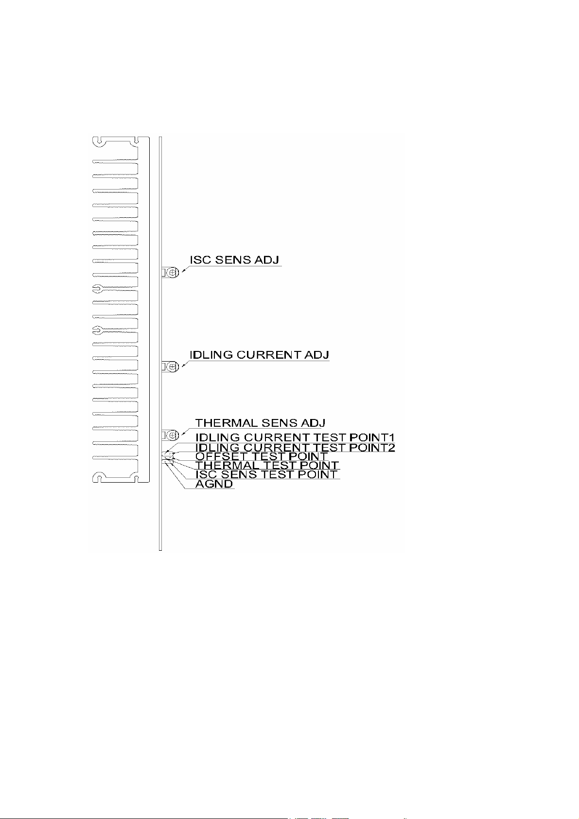
ALIGNMENT PROCEDURE (T973)
A. DC OFFSET VOLTAGE
The DC OFFSET between OFFSET Test Point and AGND must be controlled within
0+/-3mV. If it’s found to be out of this range, change the TL084BCD to get it meet the
requirement.
B. IDLING CURRENT
The idling current at the final stage of the unit should be set to about 40mA+/-10mA.
Adjust RV102 (As marked as “Idling Current ADJ” in the enclosed drawing below) to
control the voltage between Idling current Test point 1 and 2 to be 8mV +/- 2mV.
heat the unit for 10 to 15 minutes, and then readjust to 8mV +/- 2mV.
Pre
(Please note:
unit.)
C. ISC SENSITIVITY
Adjust Pot RV104 (as marked as “ISC SENS ADJ” in the below drawing) to get the voltage
across “ISC SENS TEST POINT” and AGND to be 0mV+/-10mV.
Please note that the ISC should be adjusted when all modules are assembled into the unit. It’s
(
not possible to get 0V +/-10mV if the modules are not assembled.
D. THERMAL SENSE ADJUSTMENT
The adjustment should be always done when the T973 is cool condition. (That means the
temperature inside the unit should be almost same as the ambient temperature.
Connector P208B that connects the transformer and power board should be removed to
avoid that the Idling current to heat up the unit excessively)
At ambient temperature of 25 C degree and when the unit is just turned on (still in cool
condition), adjust the pot RV103 (as marked as “THERMAL SENS ADJ” in the below
drawing) to get voltage across the THERMAL TEST POINT and AGND to be 750mV
+/-10mV. While the ambient temperature is different, the voltage will vary as well. There
is a relation between the temperature and voltage, that is; if the ambient temperature is 20
degree C, the voltage should be 850mV+/-10mV; if the ambient temperature is 30 degree
C, the voltage should be adjusted to 650mV+/-10mV, etc.
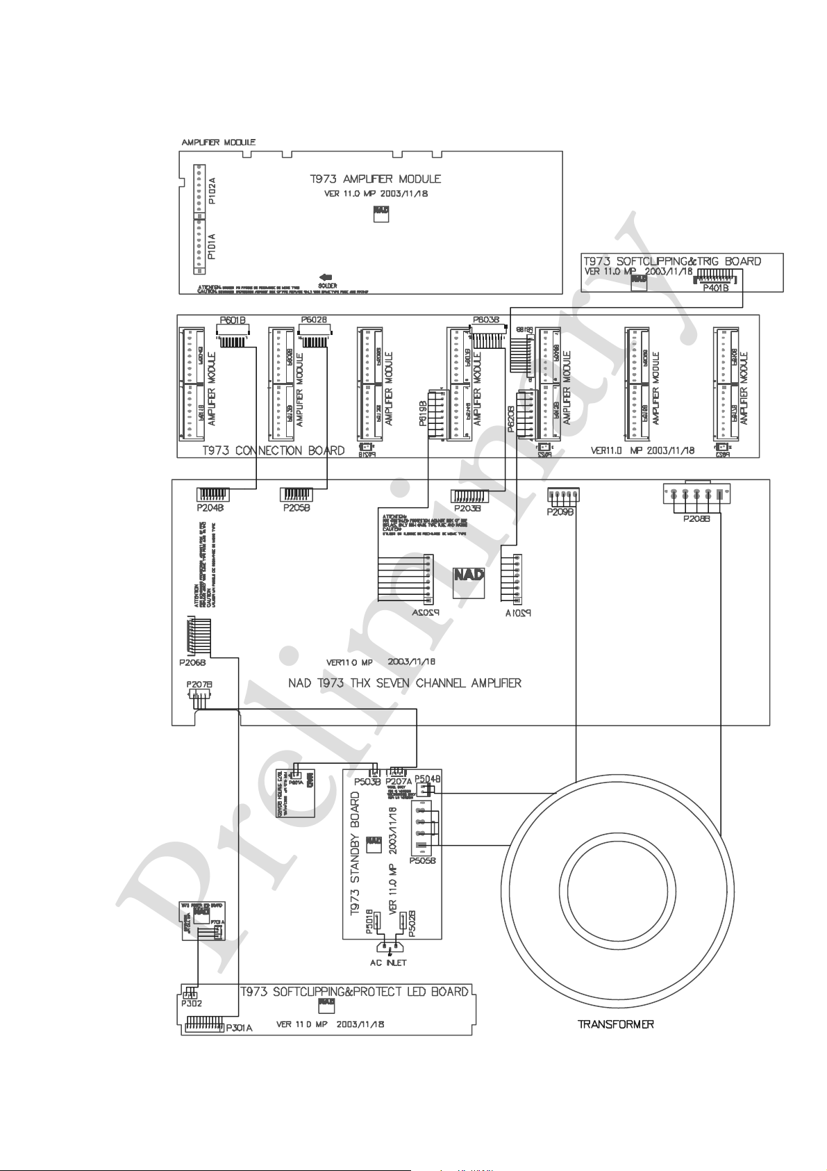
E. Fan Cut Off Point Adjustment
Note: This Fan cut off function does not appear on PCB V10.0, V11.0 or MKII version but
only appeared on PCB V12.0. Run the unit for all 7 channels at 1 kHz, 4ohms load, and
250mW output. Do this adjustment when the unit heats up, for example; run the unit at
all 7 channels at 50W/4ohms for 10 minutes. Then adjust Pot RV201 on power supply
board so the voltage at Pin14 of IC203 just changes from negative to positive (to get the
fans just start turning). Then turn off the input signal and monitor if fans will stop within 30
seconds, then turn on the input signal again to see if the fans start turning immediately.
The idling current must be adjusted when all modules are assembled into the
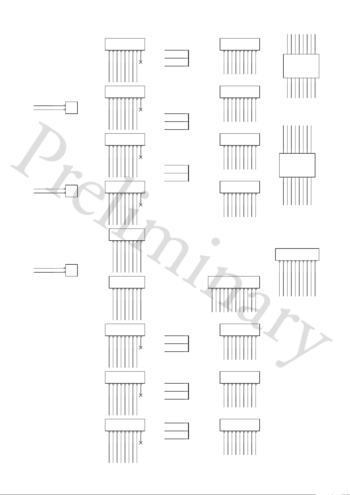
T 973 WIRING DIAGRAM
ar y
l
e
n
mi
i
Pr
Pr
e
l
i
mi
n
ar y
MOLEX 2145/3215 TOP ENTRY/9PIN
MOLEX 2145/3215 TOP ENTRY/9PIN
MOLEX 2145/3215 TOP ENTRY/9PIN
MOLEX 2145/3215 TOP ENTRY/9PIN
MOLEX 52207 RIGHT ANGLE/SMT/ZIF/TOP CONTACT STYLE/16PIN
MOLEX 52207 RIGHT ANGLE/SMT/ZIF/TOP CONTACT STYLE/16PIN
SCHEMATIC DIAGRAM(AMP CONNECTION)
FAN1
DGND
FAN2
DGND
15
16
STBY
15
16
STBY
SEN2
SEN3
SEN1
SEN7
P604B
P611B
P611B
COPPER STRIP
11223344556677889
9
AGND4A
+62V_4A
-62V_4A
-62V_4A
AGND4B
-62V_4B
-62V_4B
AGND4
-62V_4
-62V_4
+62V_4A
MOLEX 2145/3215 TOP ENTRY/9PIN
MOLEX 2145/3215 TOP ENTRY/9PIN
11223344556677889
+62V_4B
+62V_4B
11223344556677889
+62V_4
+62V_4
MOLEX 2145/3215 TOP ENTRY/9PIN
MOLEX 2145/3215 TOP ENTRY/9PIN
11223344556677889
ISCTRIG_1 ISCTRIG_3 ISCTRIG_5 ISCTRIG_6 ISCTRIG_7
AGND4A
AGND4A
P621B
HEADER 2
P621B
1
2
1
2
HEADER 2
P622
HEADER 2
P622
HEADER 2
1
2
1
2
9
AGND4B
ISCTRIG_2
AGND4B
MOLEX 2145/3215 TOP ENTRY/9PIN
MOLEX 2145/3215 TOP ENTRY/9PIN
P613B
P613B
9
AGND4
AGND4
9
P612B
P612B
P614B
P614B
+62V_4A
+62V_4B
+62V_4
-62V_4A
-62V_4B
-62V_4
AGND4A
AGND4B
AGND4
COPPER STRIP
BUS601
BUS601
COPPER STRIP
COPPER STRIP
BUS602
BUS602
COPPER STRIP
COPPER STRIP
BUS603
BUS603
P604B
11223344556677889
9
MOLEX 2145/3215 TOP ENTRY/9PIN
-68V
ACOFF
+68V
PROT1
SEN1
9
-68V
ACOFF
+68V
PROT2
SEN2
MOLEX 2145/3215 TOP ENTRY/9PIN
MOLEX 2145/3215 TOP ENTRY/9PIN
P606B
P606B
9
-68V
ACOFF
+68V
PROT3
SEN3
9
MOLEX 2145/3215 TOP ENTRY/9PIN
SCN_4
+18V
-18V
SCP_4
P605B
P605B
11223344556677889
SCN_4
+18V
-18V
SCP_4
11223344556677889
SCN_4
+18V
-18V
SCP_4
MOLEX 2145/3215 TOP ENTRY/9PIN
MOLEX 2145/3215 TOP ENTRY/9PIN
P607B
P607B
11223344556677889
PROT3
+8V
PROT4
+8V
SEN5
SEN4
101214
AGND
SEN6
101214
8
DGND
SCLED
PROT1
PROT2
AGND
135791113
P601B
P601B
246
8
PROT6
DGND
SCLED
PROT7
PROT5
MOLEX 52207 RIGHT ANGLE/SMT/ZIF/TOP CONTACT STYLE/16PIN
MOLEX 52207 RIGHT ANGLE/SMT/ZIF/TOP CONTACT STYLE/16PIN
ISCTRIG_6
ISCTRIG_2
DGND
ISCTRIG_4
135791113
P602B
P602B
246
ISCTRIG_7
ISCTRIG_5
ISCTRIG_3
ISCTRIG_1
FAN3
DGND
1
2
P623
HEADER 2
P623
HEADER 2
1
2
AGND4
ISCTRIG_4
MOLEX 5145-NCH TOP ENTRY/8PIN
MOLEX 5145-NCH TOP ENTRY/8PIN
P619B
P619B
8
AGND4
AGND4
8
AGND6
AGND6
MOLEX 2145/3215 TOP ENTRY/9PIN
MOLEX 2145/3215 TOP ENTRY/9PIN
AGND4
AGND4
AGND4
AGND6
AGND6
+62V_4
112233445566778
-62V_4
+62V_4
+62V_4
-62V_4
MOLEX 5145-NCH TOP ENTRY/8PIN
MOLEX 5145-NCH TOP ENTRY/8PIN
P620B
P620B
112233445566778
+62V_3
-62V_3
+62V_3
-62V_3
+62V_4
-62V_4
-62V_4
AGND4
P615B
P615B
11223344556677889
9
+62V_3
-62V_3
-62V_3
AGND6
AGND6
9
AGND6A
AGND6A
MOLEX 2145/3215 TOP ENTRY/9PIN
MOLEX 2145/3215 TOP ENTRY/9PIN
AGND6
AGND6A
-62V_3A
-62V_3A
+62V_3
MOLEX 2145/3215 TOP ENTRY/9PIN
MOLEX 2145/3215 TOP ENTRY/9PIN
P616B
P616B
11223344556677889
+62V_3A
+62V_3A
+62V_3
+62V_3A
+62V_3B
-62V_3
-62V_3A
-62V_3B
ACOFF
SEN4
MOLEX 51021/12PIN/500mm WIRE
MOLEX 51021/12PIN/500mm WIRE
101112
SCP_4
+62V_3
-62V_3
-62V_4
+62V_4
COPPER STRIP
COPPER STRIP
BUS604
BUS604
9
ACOFF
SEN5
MOLEX 2145/3215 TOP ENTRY/9PIN
MOLEX 2145/3215 TOP ENTRY/9PIN
P609B
P609B
COPPER STRIP
COPPER STRIP
BUS605
BUS605
9
ACOFF
SEN6
-68V
PROT4
SCN_4
SCP_3
-68V
PROT5
-18V
+68V
SCLED
SCN_3
-18V
+68V
SCN_4
+18V
SCP_4
S10B-PH-SM3-TB
S10B-PH-SM3-TB
P603B
P603B
10
10
9
P618B
P618B
123456789
+8V
DGND
STBY
MOLEX 2145/3215 TOP ENTRY/9PIN
MOLEX 2145/3215 TOP ENTRY/9PIN
11223344556677889
SCN_3
+18V
SCP_3
11223344556677889
P608B
P608B
AGND
FAN1
FAN2
FAN3
-68V
+68V
ACOFF
+18V
-18V
11223344556677889
-68V
PROT6
-18V
+68V
SCN_3
+18V
SCP_3
MOLEX 2145/3215 TOP ENTRY/9PIN
MOLEX 2145/3215 TOP ENTRY/9PIN
DGND
P617B
P617B
9
AGND6B
AGND6B
-62V_3B
AGND6B
11223344556677889
+62V_3B
-62V_3B
+62V_3B
AGND6
AGND6A
AGND6B
COPPER STRIP
COPPER STRIP
BUS606
BUS606
9
ACOFF
SEN7
-68V
PROT7
-18V
+68V
+18V
SCP_3
11223344556677889
SCN_3
P610B
P610B
 Loading...