

Page 1

DRAFT DATE: 30 OCT, 2002
NAD
SERVICE MANUAL
T 571
DVD / VCD / CD
PLAYER
T 571
DVD / VCD / CD
PLAYER
Page 2

CONTENTS
SECTION 1 . . . .SUMMARY
SECTION 2 . . . .CABINET & MAIN CHASSIS
SECTION 3 . . . .ELECTRICAL
SECTION 4 . . . .MECHANISM
SECTION 5 . . . .REPLACEMENT PARTS LIST
Page 3

SECTION 1
SUMMARY
CONTENTS
PRODUCT SAFETY SERVICING GUIDELINES FOR VIDEO PRODUCTS
........................... 1-3
SERVICING PRECAUTIONS .................................................................................................. 1-4
• General Servicing Precautions
• Insulation Checking Prodedure
• Electrostatically Sensitive Devices
SPECIFICATIONS ...................................................................................................................... 1-5
Page 4
1-3
Prior to shipment from the factory, the products are strictly inspected to conform with the recognized product
safety and electrical codes of the countries in which they are to be sold. However, in order to maintain such compliance, it is equally important to implement the following precautions when a set is being serviced.
• Precautions during Servicing
1. Locations requiring special caution are denoted by labels and inscriptions on the cabinet, chassis and
certain parts of the product. When performing service, be sure to read and comply with these and other
cautionary notices appearing in the operation and service manuals.
2. Parts identified by the symbol and shaded (
Y
) parts are critical for safety.
Replace only with specified part numbers.
Note : Parts in this category also include those specified to comply with X-ray emission standards for
products using cathode ray tubes and those specified for compliance with various regulations
regarding spurious radiation emission.
3. Use Specified internal wiring. Note especially:
1) Double insulated wires
2) High voltage leads
4. Use specified insulating materials for hazardous live parts. Note especially:
1) Insulation Tape
2) PVC tubing
3) Spacers
4) Insulation sheets for transistor
5. Observe that wires do not contact heat producing
parts (heatsinks, oxide metal film resistors, fusible
resistors, etc.)
6. Check that replaced wires do not contact sharp edged
or pointed parts.
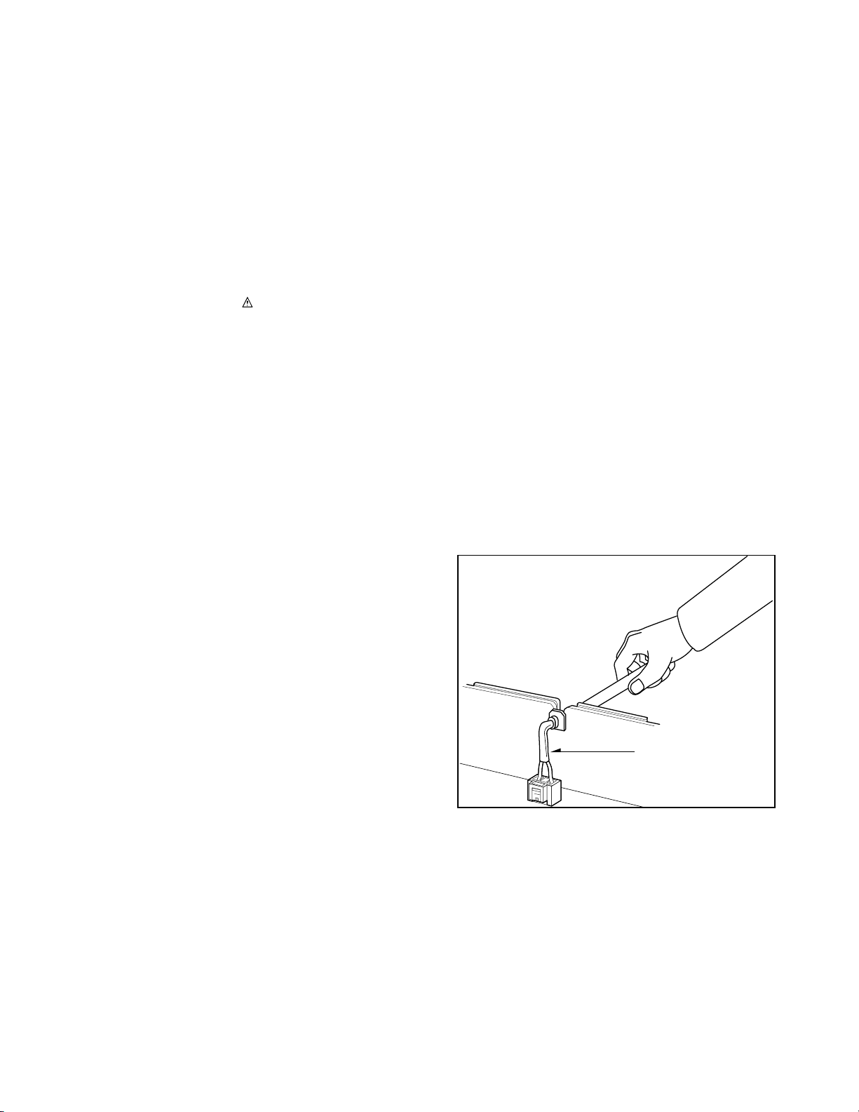
7. 1) When a power cord has been replaced, check
that A mark is made on the cord, under strain,
near the aperture, and the flexible cord is
subjected 100 times to a pull of 40N for a duration
of 1 second each.
2) During the test, the cord shall not be displaced by
more than 2mm
8. Also check areas surrounding repaired locations.
IMPORTANT SAFETY PRECAUTIONS
Fig. 1
Power cord
Page 5
1-4
Fig. 3
SAFETY CHECK AFTER SERVICING
Examine the area surrounding the repaired location for damage or deterioration. Observe that screws, parts and
wires have been returned to original positions. Afterwards, perform the following tests and confirm the specified
values in order to verify compliance with safety standards.
• Insulation resistance test
confirm the specified insulation resistance or greater between power cord plug prongs and externally exposed
parts of the set (RF terminals, antenna terminals, video and audio input and output terminals, microphone
jacks, earphone jacks, etc.) See table below.
• Dielectric strength test
Confirm specified dielectric strength or greater between power cord prongs and exposed accessible parts of
the set (RF terminals, antenna terminals, video and
audio input and output terminals, microphone jacks,
earphone jacks, etc.) See table below.
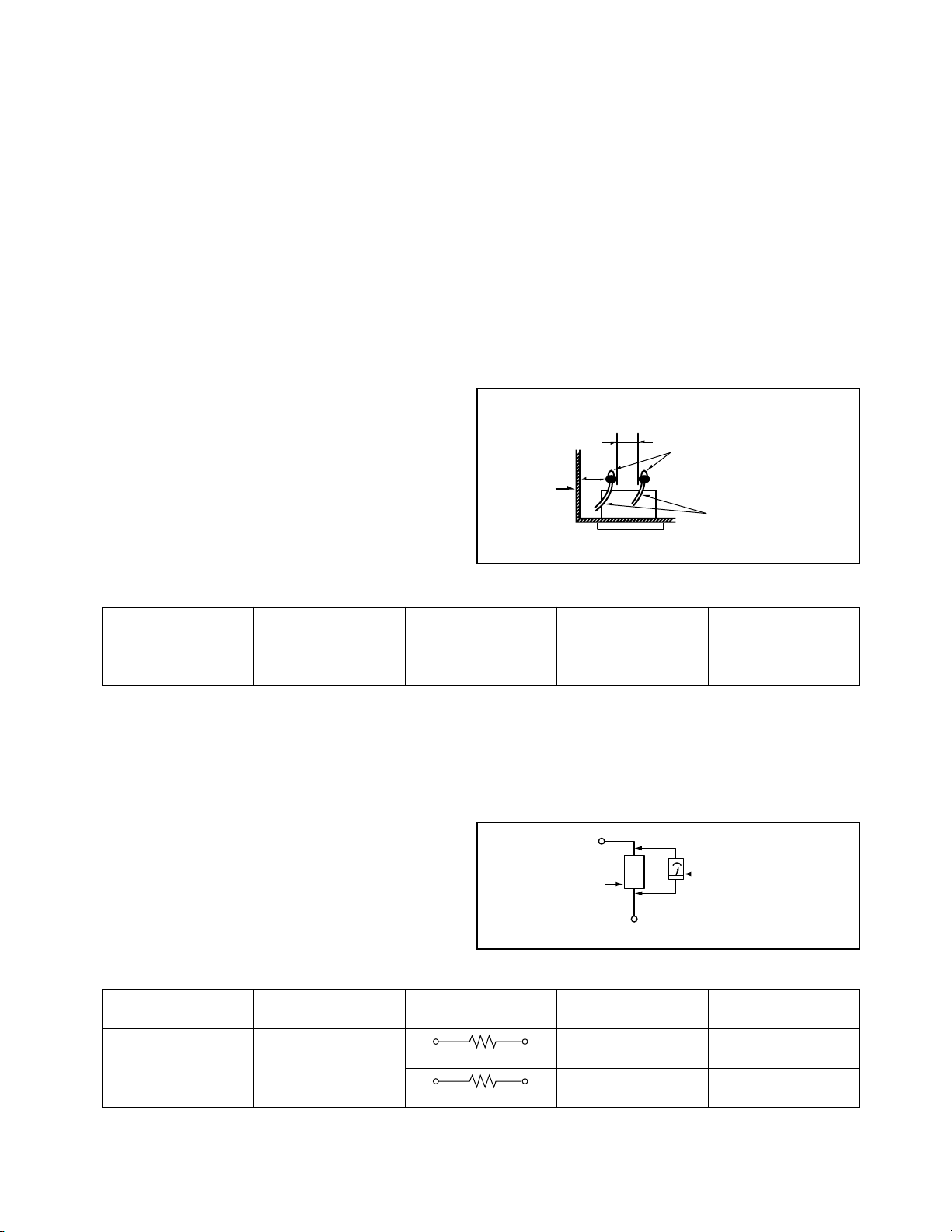
• Clearance distance
When replacing primary circuit components, confirm
specified clearance distance (d), (d') between soldered terminals, and between terminals and surrounding metallic parts. See table below.
Table 1 : Ratings for selected areas
* Class II model only.
Note. This table is unofficial and for reference only. Be sure to confirm the precise values for your particular
country and locality.
• Leakage Current test
Confirm specified or lower leakage current between B(earth ground, power cord plug prongs) and externally
exposed accessible parts (RF terminals, antenna terminals, video and audio input and output terminals, microphone jacks, earphone jacks, etc.)
Measuring Method: (Power ON)
Insert load Z between B(earth ground, power cord
plug prongs) and exposed accessible parts. Use an
AC voltmeter to measure across both terminals of
load Z. See figure and following table.
Table 2:Leakage current ratings for selected areas.
Note. This table is for IEC member only. Be sure to confirm the precise values for your particular country and
Note. locality.
Fig. 2
AC Line Voltage
AC Line Voltage
200 to 240 V
100 to 130 V
*200 to 240 V
*100 to 130 V
Europe
Australia
Europe
Australia
Other terminals
Antenna earth
terminals
i
E 0.7m A peak
i
E 2m A DC
i
E 0.7m A peak
i
E 2m A DC
F 10 MΩ/500 V DC
4kV 1 minute
F 6mm(d)
F 8mm(d)
(a Power cord)
Region
Load Z Leakage Current(i)
Earth Ground
(B) to :
Region
Insulation
Resistance
Dielectric
Strength
Clearance
Distance(d),(d)
2k
Ω
50k
Ω
d
Primary circuit terminals
Chassis
a
Exposed
accessible
part
Load
Z
Earth Ground,
Power cord plug prongs
B
AC Voltmeter
Page 6

1-5
SPECIFICATIONS
DVD VIDEO PLAYER
Power supply AC 120 V, 60 Hz (T571AH)
AC 110~240 V, 50/60 Hz (T571C)
Power consumtion 16 W
Mass 5.7 kg(12.6 lbs)
External dimensions 440 x 118 x 423 mm (W x H x D)
Signal system NTSC (T571AH)
PAL (T571C)
Laser (DVD) Semiconductor laser, wavelength 650 nm
(CD) 780 nm
Frequency range (audio) DVD : fs = 96 kHz 4 Hz - 44 kHz
fs = 48 kHz 4 Hz - 22 kHz
CD: 4 Hz - 20 kHz
Signal-to-noise ratio (audio) More than 105dB (EIAJ)
Audio dynamic range (audio) More than 100dB (EIAJ)
Harmonic distortion(audio) 0.003%
Wow and flutter Below measurable level (less than +0.001%(W.PEAK)) (EIAJ)
Operations Temperature : 5˚C(41˚F) to 35˚C(95˚F),
Operation status : Horizontal
OUTPUTS
Video outputs 1.0V(p-p), 75Ω, negative sync., RCA jack x 1/
SCART(TO TV) (T571C ONLY)
S-video outputs (Y)1.0V(p-p), 75Ω, negative sync.,Mini DIN 4-pin x 1
(C)0.286V(p-p), 75Ω
Component video output (Y)1.0V(p-p), 75Ω,negative sync., RCA jack x 1
(Pb)/(Pr) 0.7V(p-p), 75Ω
Audio output(digital audio) 0.5V(p-p), 75Ω, RCA jack X 1/SCART(TO TV) (T571C ONLY)
Audio output(analog audio) 2.0Vrms (1kHz, 0dB), 330Ω, RCA jack (L, R) x 2/
SCART(TO TV) (T571C ONLY)
*Designs and specifications are subject to change without notice.
Page 7

2-1
SECTION 2
CABINET & MAIN CHASSIS
CONTENTS
1. DISASSEMBLY.........................................................................................................................2-2
CABINET DISASSEMBLY ............................................................................................................2-2
CIRCUIT BOARD DISASSEMBLY ...............................................................................................2-3
2. EXPLODED VIEWS ................................................................................................................2-4
1. Cabinet and Main Frame Section...........................................................................................2-4
2. Packing Accessory Section ....................................................................................................2-5
Page 8
2-2
DISASSEMBLY
CAUTION BEFORE STARTING SERVICING
Electronic parts are susceptible to static electricity and may easily and damaged, so do not forget to take a
proper grounding treatment as required.
Many screws are used inside the unit. To prevent missing, dropping, etc. of the screws, always use a
magnetized screw driver in servicing. Several kinds of screws are used and some of them need special
cautions. That is, take care of the tapping screws securing molded parts and fine pitch screws used to secure
metal parts. If they are used improperly , the screw holes will be easily damaged and the parts can not be fixed.
Top Case
(A)
(A)
(A)
(A)
(A)
(A)
(A)
Disc Tray
Tray Door
Front Panel
Stopper
Stopper
CABINET DISASSEMBLY
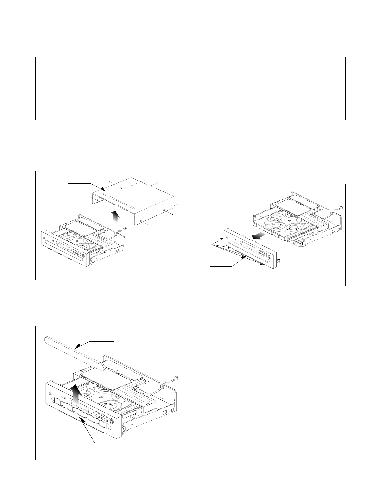
1. Top Case
1. Release 7 screws (A). (See Fig. 2-1)
2. Lift the top case with holding the back of it,
and remove it in the direction of the arrow.
Fig. 2-1
Fig. 2-2
Fig. 2-3
3. Front Panel
1. Eject the disc tray. (See Fig. 2-2)
2. Remove the tray door. (See Fig. 2-2)
3. Pull the front panel toward you while pressing
5 stoppers to disengage, and remove the front
panel. (See Fig. 2-3)
2.Tray Door
1. Eject the disc tray.
2. Lift up the tray door in the direction of the
arrow.
Page 9
2-3
(L1)
(L1)
(B)
(B)
(C)
(C)
(C)
Power Code
Power
Circuit
Board
Main Chassis
MA Ass'y Dpm1
Bracket Main
Jack Circuit Board
(F)
(F)
(F)
(F)
Main Circuit Board
(B)
(B)
(D)
(E)
(D)
(D)
(D)
(E)
(E)
(B)
(B)
Fig. 2-4
Fig. 2-5
1. Disassemble Main circuit board, Jack
circuit board, Power circuit board and
MD Ass'y DPM1.
1. Remove the top case.(See Fig. 2-1)
2. Remove 10 screws (B).
3. Disassemble Main circuit board and Jack circuit
board from Bracket Main.
4. Unscrew 3 screws(C) at Bracket Main.
5. Disassemble Bracket Main from Main chassis.
6. Unscrew 4 screws(D) at MD Ass'y DPM1.
7. Turn the portion the direction of arrow to move
the Base Assembly Tray in front of you.
8. Release the other 3 screws(E).
9. Disassemble MD Ass'y DPM1 from Main chassis.
10. Unscrew 4 screws(F) at Power circuit.
11. Disassemble power circuit board from Main
chassis.
CIRCUIT BOARD DISASSEMBLY
Note: Before removing the main circuit board, be sure to shortcircuit the laserdiode output land.
After replacing the main circuit board, open the land after inserting the flexible connector.
(Refer to Mechanism Disassembly)
2. Digitron and Key Circuit Board
1. Remove the front panel.(See Fig. 2-3)
2. Release 6 screws (G), and remove the digitron
circuit board.
(G)
(G)
(G)
(G)
(G)
(G)
Page 10
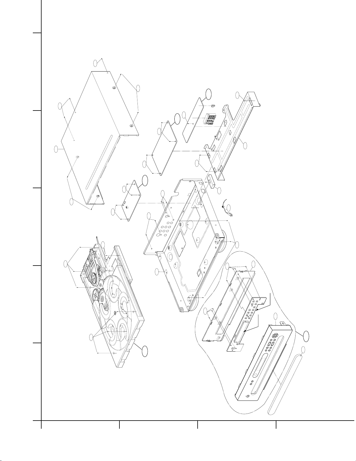
2-4
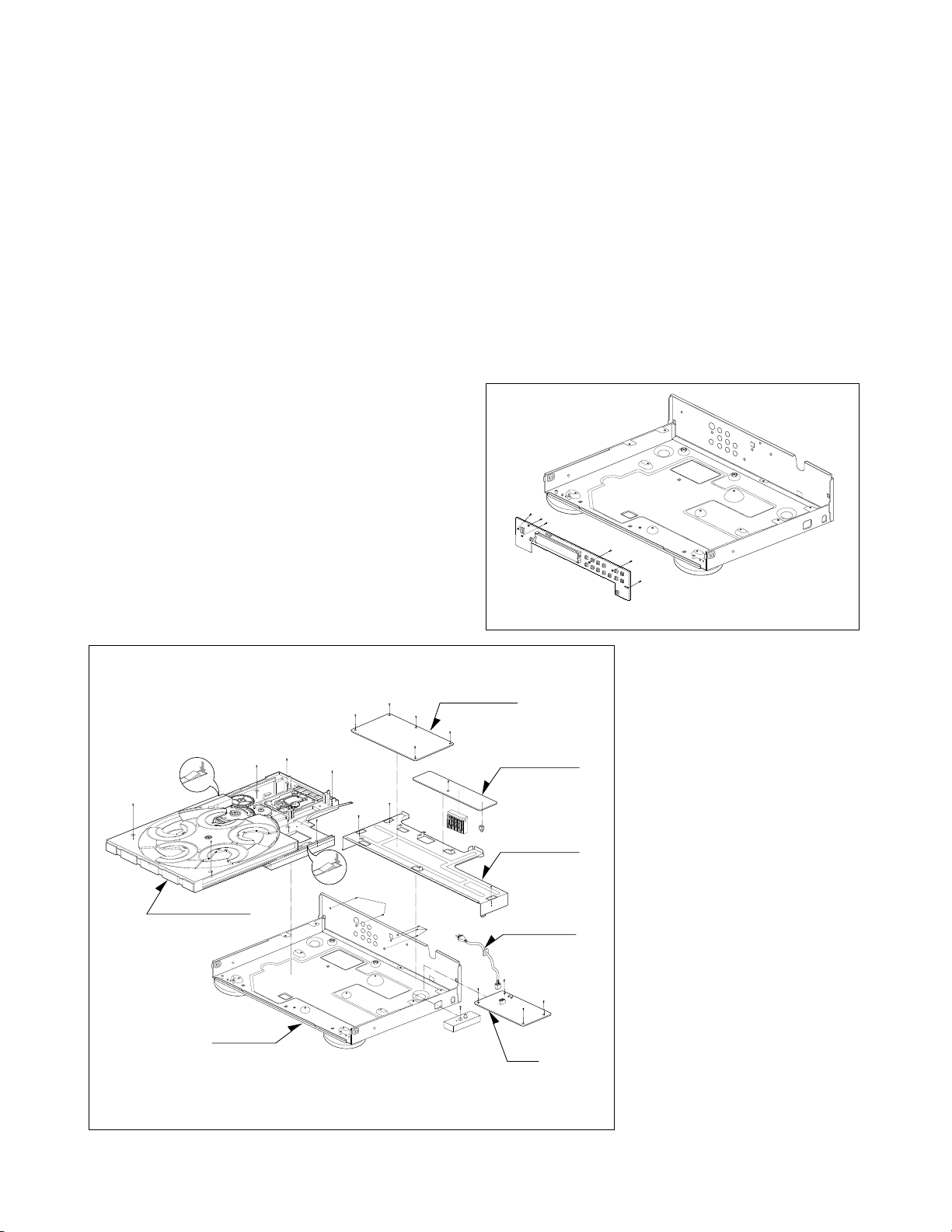
EXPLODED VIEWS
1. Cabinet and Main Frame Section
465
465
250
462
462
300
465
260
465
A46
A47
463
463
275
463
463
463
467
A48
463
463
463
463
463
A00
A43
280
285
262
452
452
DIG901
PBTOO
283
A
5
4
3
2
1
BCD
Page 11
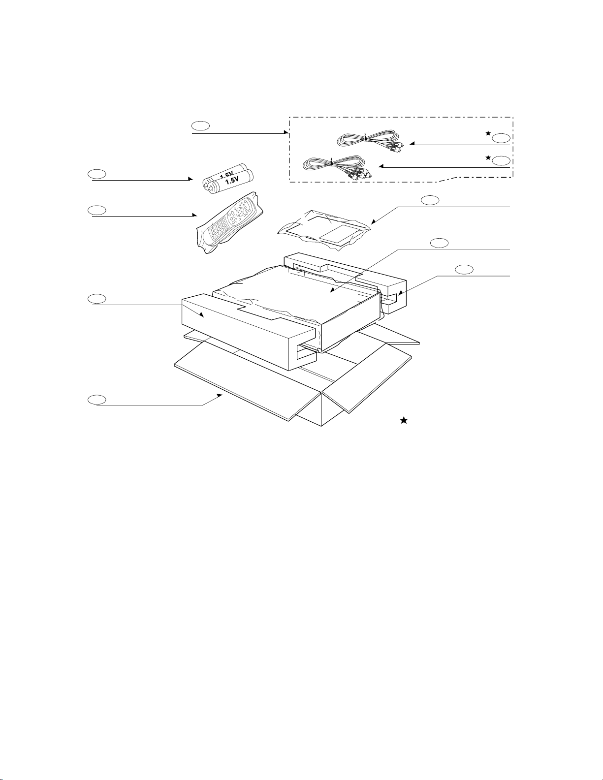
2-5
2.Packing Accessory Section
BATTERY
808
PACKING SHEET
804
PACKING
OPTIONAL PARTS
803
811
812
OWNER'S MANUAL
810
CABLE SET ASS'Y
801
REMOCON
900
BOX CARTON
802
PACKING
803
Page 12

3-1
SECTION 3
ELECTRICAL
CONTENTS
ELECTRICAL TROUBLESHOOTING GUIDE......................................................................3-2
1. Power(SMPS) Circuit...............................................................................................................3-2
2. µ-com Circuit............................................................................................................................3-3
3. MPEG Circuit ............................................................................................................................3-6
4. Front Circuit(Digitron & Key) ................................................................................................3-7
5. RF/Servo Circuit ......................................................................................................................3-8
BLOCK DIAGRAMS..................................................................................................................3-12
1. Overall Block Diagram ..........................................................................................................3-12
2. Power (SMPS) Block Diagram..............................................................................................3-13
3. RF/CD DSP/DVD DSP/DVD servo Block Diagram ..............................................................3-14
4. Audio Block Diagram ............................................................................................................3-15
5. MPEG Block Diagram ...........................................................................................................3-16
CIRCUIT DIAGRAMS................................................................................................................3-17
1. Power (SMPS) Circuit Diagram ............................................................................................3-17
2. DVD DSP Circuit Diagram.....................................................................................................3-19
3. Drive & RF Circuit Diagram ..................................................................................................3-21
4. MPEG Circuit Diagram ..........................................................................................................3-23
• WAVEFORMS ...........................................................................................................................3-25
5. Audio DM & 5.1CH Circuit Diagram.....................................................................................3-27
6. TIMER & Key Circuit Diagram ..............................................................................................3-29
7. A/V Circuit Diagram...............................................................................................................3-31
8. A/V Jack Circuit Diagram......................................................................................................3-33
9. SCART Circuit Diagram.........................................................................................................3-35
• CIRCUIT VOLTAGE CHART.........................................................................................................3-37
PRINTED CIRCUIT DIAGRAMS............................................................................................3-41
1. MAIN P.C.BOARD...................................................................................................................3-41
2. AV JACK P.C.BOARD........................................................................................................... ..3-43
3. SMPS P.C.BOARD..................................................................................................................3-44
4. FRONT P.C.BOARD ................................................................................................................3-43
Page 13
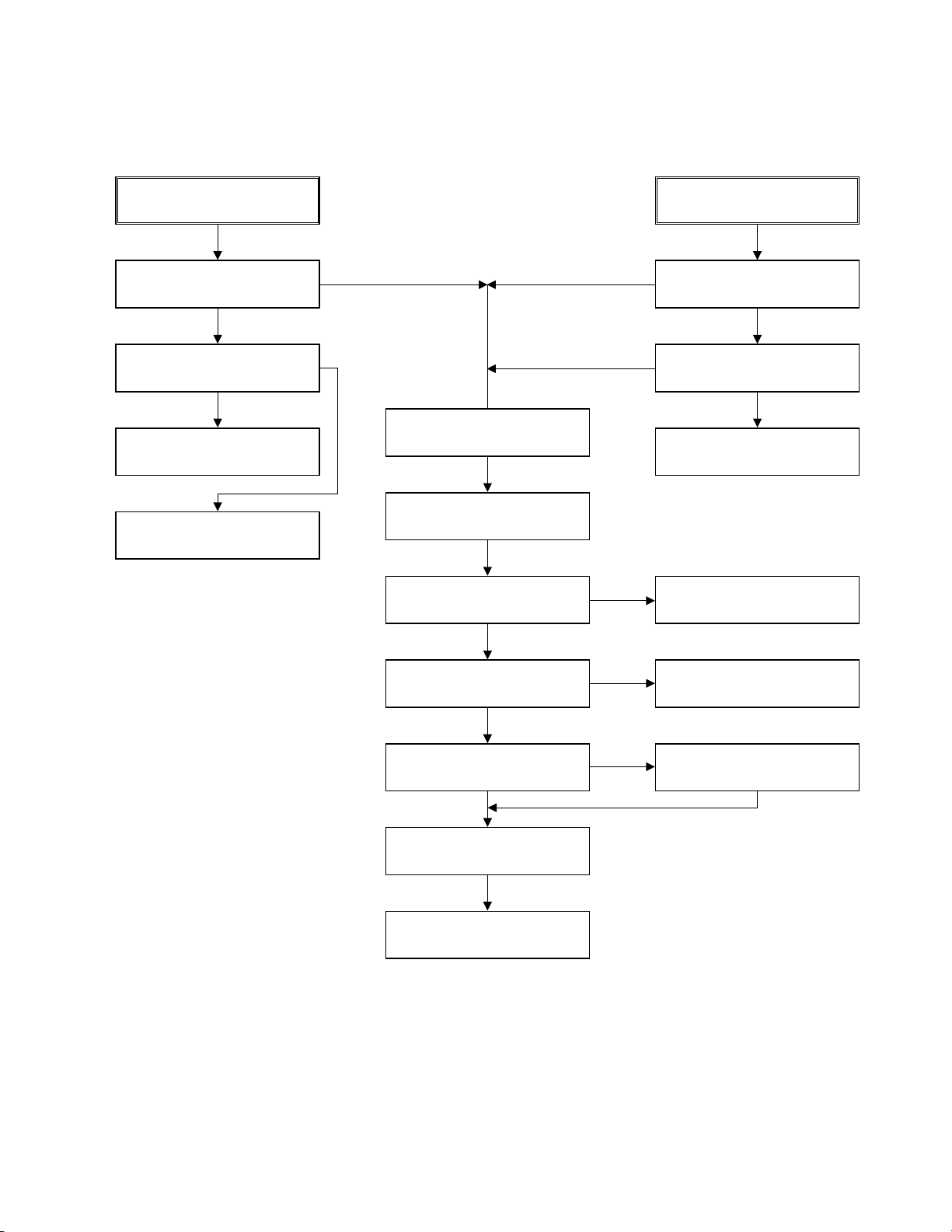
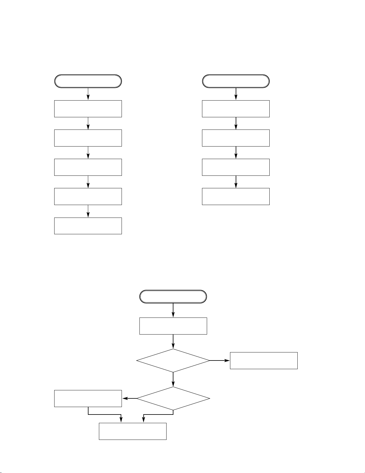
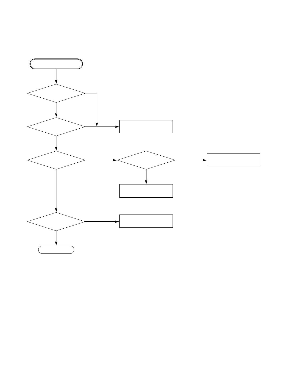
3-2
ELECTRICAL TROUBLESHOOTING GUIDE
No 5V_D
or 5V_A .
No 5.2VA.
Is 5.2VA section working?
(Is the POWER CTL at
Pin6 High/low?)
Is oscillation present at the
Base of Q108?
Replace Q108.
Check D109, C123, R125,
R124.
Replace R102.
Replace BD101.
(Bridge rectifier)
Is R102(R104) normal?
Is about AC 100V app;ied to
IC101 Pin 3.
Check IC101.
Is 5.2V applied to IC102
Pin 1?
Is there a DC voltage at the
(+) terminal of BD101?
Check R127, 128.
(SHUTDOWN CKT)
1. Power(SMPS) Circuit
No FLD
Is 5.2VA section working?
Replace SMPS trans(T101).
Replace the inferior
components.
Are D109, L103 open?
NO
NO
NO
NO
NO
NO
YES
YES
YES
YES
YES
YES
YES
A. B.
NO
NO
Page 14
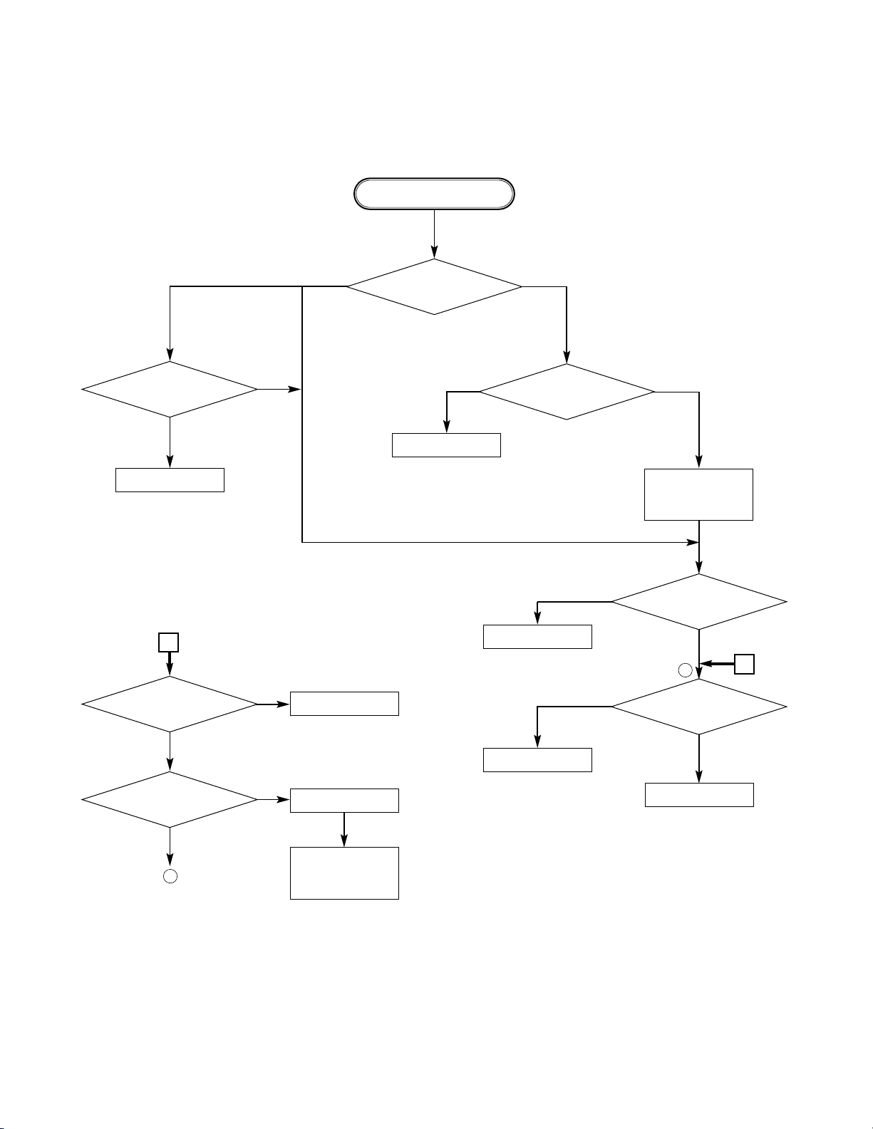
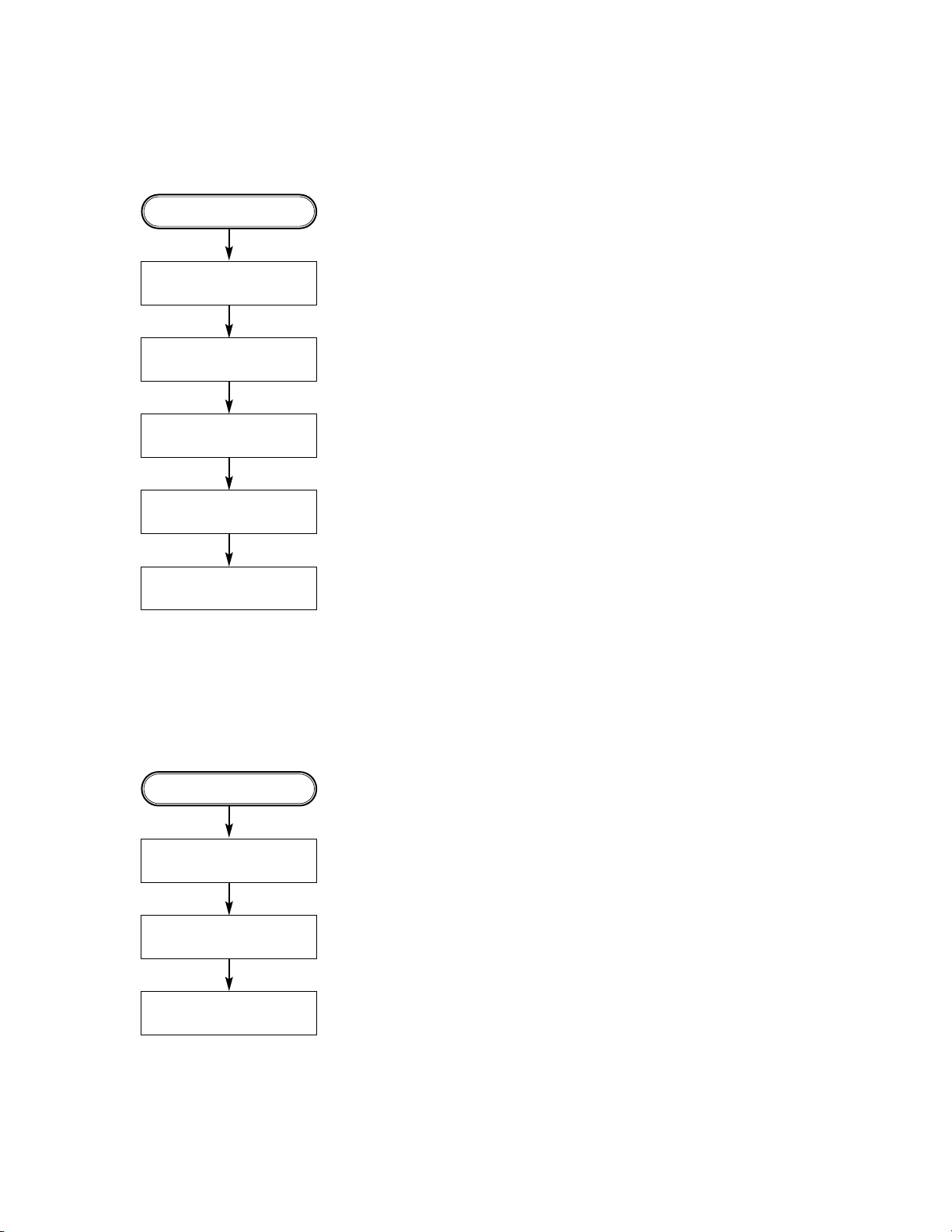
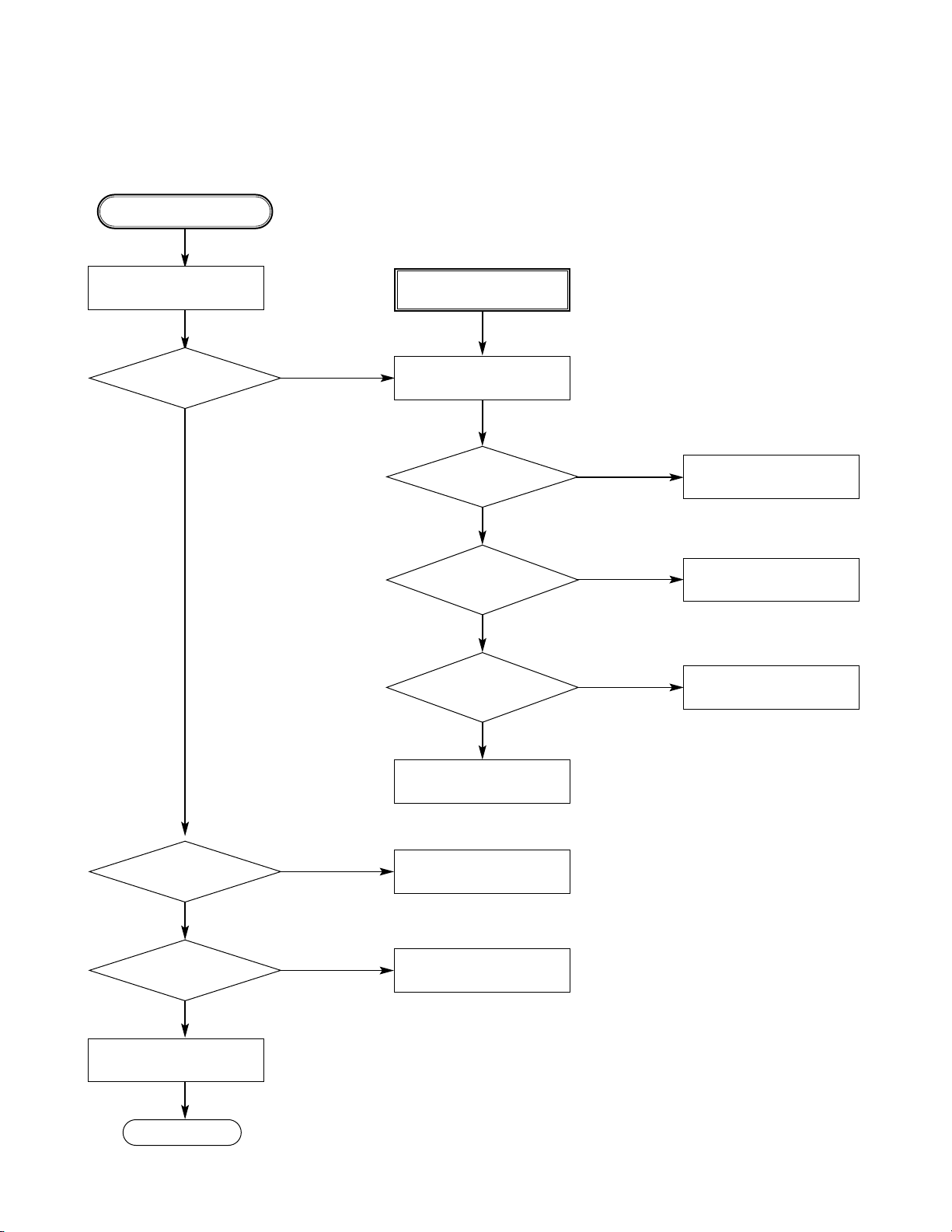
3-3
Replace Main B/D
Refer to Front Part
Replace IC502
Reconnect it.
2. µ-COM Circuit
A. No Power
Does Logo appear
on the screen?
Is oscillation of
X501 normal?
Are IC501 Pins 193, 808
and 81 normal?
Do “Hello” appear at FLD?
Is P3901
connected normally?
Is P3901 Pin 8, 9, 18 normal?
The waveform
on 3, 5, 7 pin of IC502
normal?
Check the oscillation
Check short.
OK
Replace IC501
or IC306.
Check power.
(Refer to power)
If power is
normal
OK
POWER ON
1
1
YES
YES
YES
YES
NO
YES
YES
YES
A
NO
NO
NO
NO
NO
NONO
YES
A
Page 15
3-4
B. Audio abnormal
D. Open/Close abnormal
Check the
connection of P3901.
Check IC301 Pins 93, 94.
Check Audio jack.
YES (If OK)
YES
NO
NO
YES
YES
(If OK)
YES
YES
(If OK)
YES (If OK)
YES (If OK)
Refer to Audio part.
Refer to Decoder part.
Refer to PANTERApart.
Replace B/D.
Check Front.
Reconnect it.
Refer to SERVO part.
Check the connection of MD.
AUDIO ABNORMAL
OPEN/CLOSE ABNORMAL
C. Video abnormal
Check Video jack.
YES (If OK)
YES (If OK)
YES (If OK)
Refer to Video part.
Refer to PANTERApart.
Replace B/D.
VIDEO ABNORMAL
Page 16
3-5
E. Picture abnormal
Check the disc.
If OK
YES (If OK)
YES (If OK)
Refer to Servo part
Check DSP
Check PANTERA
Replace B/D
PICTURE ABNORMAL
F. Disc Error
Check Disc
YES (If OK)
YES (If OK)
Refer to Servo part
Replace B/D
DISC ERROR
Page 17
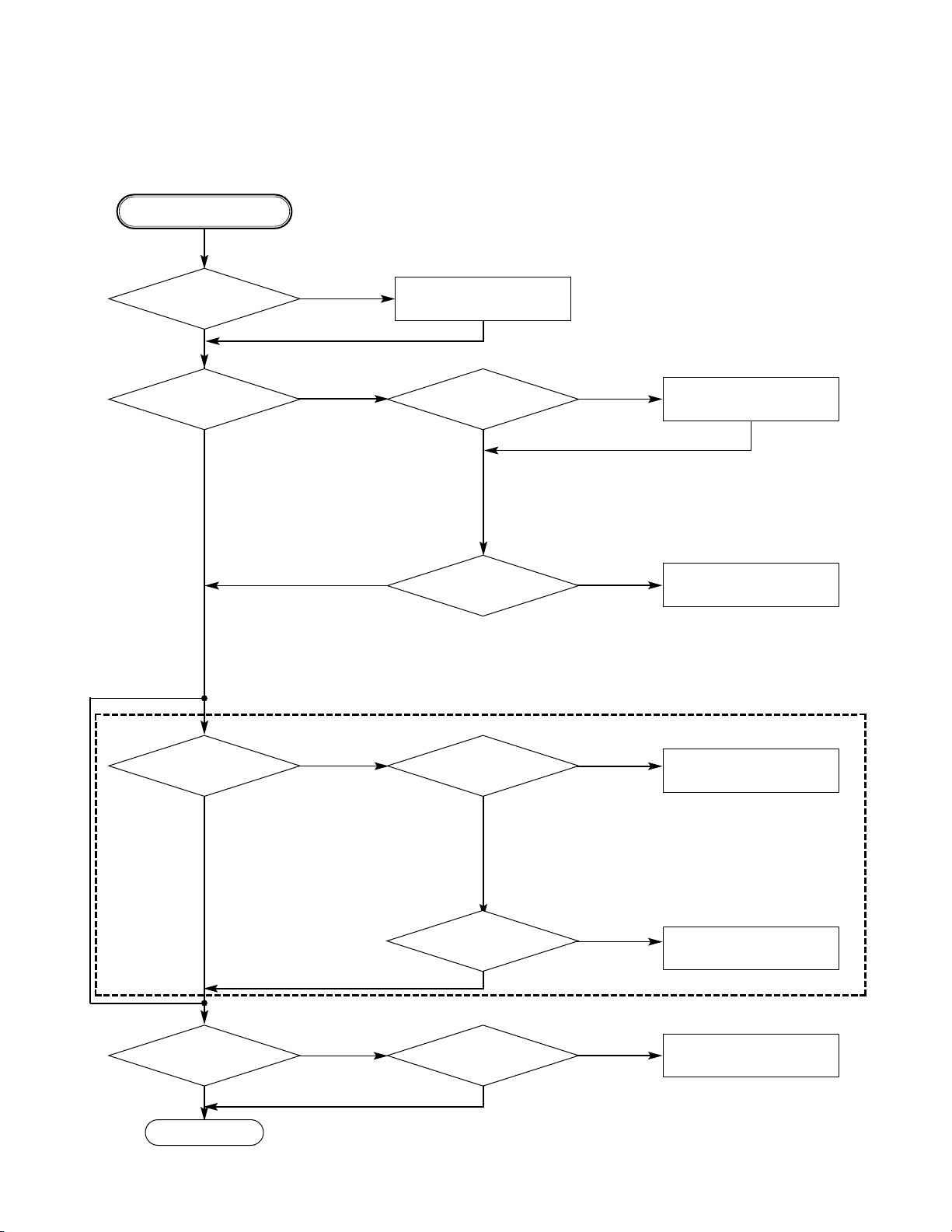
3-6
Power is on
Does TOSHIBA Logo appear
on the screen?
Does the
moving picture of the DVD Disc
play on the screen
normally?
Is PANTERA
data signal normal?
Is error signal normal?
Is PANTERAdata
signal normal?
Is Clock normal?
Does the audio
sound output from PANTERA
decoder?
Does the
moving picture of the video
CD play on the screen
normally?
Does the audio sound
output normally?
END
Check power & clock.
Check CD/DVD DSP output
signal.
Check CD/DVD DSP output
signal.
Check CD/DVD DSP output
signal.
Check clock signal
Check clock signal
YES
YES
YES
YES
YES
YES
YES
YES
YES
YES
NO
NO
NO
OK
NO
NO
NO
NO
NO
3. PANTERA Circuit
_ OPTION
_ If included VCD function.
Page 18
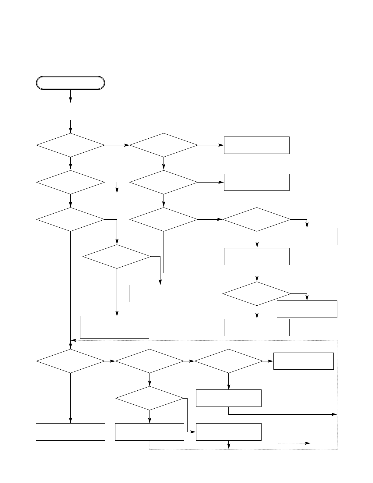
3-7
NO
NO
NO
START
Does remote control
work normally?
Do all the
buttons work
normally?
Check waveform of
IC901 Pin 21, 22.
Check waveform
of IC901 Pin 27.
Is Digitron on normally?
LED ON?
Check waveform
of IC901 Pin 6.
Is oscillation of
X901 normal?
Is waveform of IC901
Pin 40 normal?
Check waveform
of IC901 Pin 22.
Does pulse
waveform of RC901 Pin 1
appear?
Is IC901
Pin 17 connected to
RC901 Pin 1 ?
Is RC901 Pin 2 5V?
Power on.
Check and replace
R926, R925.
Solder defective parts again.
Solder defective parts
Replace IC901.
Solder Key part.
Check Power.
Replace IC902.
Replace IC901.
Replace LED901.
Replace RC901.
Re-solder.
Recheck
Replace IC901.Complete repairing Front B/D.
NO
NO
NO
NO
NO
NONONO
NO
YES
YES YES
YES
YES YES
YES
YES
YES
YES
YES
YES
YES
YES
YES
YES
CD
4. Front Circuit (Digitron & key)
Page 19
3-8
Does signal pulse
input to IC201 Pins 58, 59 when
the power is on?
Does signal goes
"High" to IC201 Pin194 when the
power is on?
Does
TTL pulse output to
IC201 Pins 140, 142?
Does
33.8688MHz clock input
to IC201 Pin 63?
Is IC201
Pins 83, 84, 88, 89 voltage
about 2.2V?
Replace IC201
(IC206 soldering or IC defect).
Check power circuit.
Check "2.PANTERAPart".
Replace X201 or IC206
(30MHz clock defect)
CHECK POINT(General)
5. RF/Servo Circuit
A.
END
NO
NO
NO NO
NO
YES
YES
YESYES
YES
Page 20
3-9
Does tray open or close?
Does the pick-up
slide inner or outer
track?
Fig.1. SLED Driver waveform
Fig.2. Focus Driver waveform
Does
the voltage change
at PMD03 Pins 15, 16 more than
2V on the basis of
3.8V?
Pressing
the open/close key
repeatedly, check the voltage of IC2M1
Pins 13, 14 change
0V to 5V
Does
PMD03 Pin 6 change
high to low?
Does
the pick-up lens move up
and down?
Check Focus Driver output.
(IC201 Pin 83, IC2M1 Pins 37, 38)
Check SLED Driver output.
IC201 Pin 88 IC2M1 Pins 28, 29.
IC201 Pin 88 no output : IC201 is defective
IC2M1 Pins 28, 29 no output : IC2M1 is defective
IC201 Pin 83 no output : IC201 is defective
IC2M1 Pins 37,38 no output : IC2M1 is defective
DECK assembly is defective.
Slide the pick-up to
inner track.
Power on
Check loading Part.
Push Pick-up to inner track to
the end by hand.
DECK assembly is defective.
(Limit sw)
check PANTERAPart.
Replace IC2M1.
No disc
B.
END
NO
NO
NO
NO
NO
NO
YES
YES
YES
YES
YES
YES
Page 21

3-10
FOCUS ON?
Check
the focus error moving the
lens up and down.
(IC2A1 Pin 42)
Does the
TTL level change at IC201
Pin 78 and 132 moving
the lens?
Does the disc turn?
IC201 Pin169 is "High"?
Is OK the track jump.
Does the signal
pulse appear at IC2A1 Pins
39, 29?
Does the screen appear?
OPEN/CLOSE
Replace IC501 or IC201.
Replace IC201.
Check IC2A1 Pin 11,12,13,14
in DVD Mode
Fig.3. FOCUS ERROR waveform
IC201 no output : Pick-up is defective.
Check IC201 and IC2M1 when PMD03 Pin 5 is abnormal
Check IC2M1 Pin 21, PMD03
Pin 5 turn when the IC2M1
Pin 21 is less than 2.2V.
Check A
Video Part is defective.
Check "PANTERACircuit."
Check "7.OSD/Video Circuit."
Replace PANTERApart.
IC2A1 is defective.
DISC IN
C.
END
NO
NO
NO
NO NO
NO
NO
NO
YES
YES
YES
YES
YES
YES YES
YES
Page 22

3-11
See the eye-pattern vivid?
Does the
sawtooth waveform emit
at IC2A1 Pin 41?
Does the 1.6V emit?
Check RF Eye-Pattern.
RF : 1.5-1.6V(IC2A1 Pin 57)
Fig.5. RF
waveform
Check IC2A1 Pins 5, 6, 7, 8.
No signal: Pick-up is defective
Replace IC201.
Check IC201 Pin84.
No signal at IC201 : IC201 is defective
• Check IC201 Pin 162.
• Check the clock at the IC201 Pins 28, 30.
• Both are normal : IC201 is defective
Replace IC2A1.
CHECK A
D.
END
NO
NO NO NO
YES
YES YES YES
Page 23

3-12
BLOCK DIAGRAMS
1. Overall Block Diagram
M
M
DISC
SPINDLE
MOTOR
LOADING
MOTOR
DECK MECHANISM
CD: A,B, E, F
DVD: A,B,C,D,
DVD; RF
CD: A,B, E, F
DVD: A,B,C,D,
DVD; RF
PICK
UP
IC205
DRAM
16bit
4M
IC201
HY25D801C
CD / DVD DSP
IC501
PANTERA -II/2E
IC901
Upd78032
FROM
FL DISPLAY
KEY Input
REMOCON
RECEIVER
5MHz
X-TAL
Pb
IC301
XC9572VL
CPLD
I/O PORT 72
IC304
SDRAM
16/32BIT
64M
IC502
93C46
EEPROM
IC2M1
KA3032
MOTOR
DRIVER
IC2A1
TA33P3721
RF
ICDATA
[00:15]
ICADD
[0:8]
LOADING
FOCUS,TRA CKING,SLED
SPIND LE
MIRR,TZC,PI,TE
FE,DFECT_IN
RFO
SCLK,SDATA
SCOR,SQCK,SQSO
XLAT , E_S TI , E_E NB , E_DR
RF_XLAT , LDON
IC401
PCM1716
DAC
XIO1,XIO2
,XIO10
F_CLK
F_OUT
PCMCLK
SPINDLE_FG
MSDATO
MDP1
FOK
DEFECT
DSP_SENSE
LOCK
E_SOUT
ZISENB
/XRST
DAC_RST
16
:9,PAL_SW ,AUTO_SW,MIC_ON
Y_SEL
/A_MUTE
/DAC_CS1
/DAC_CS2
V_MUTE
DAC_CLK
DAC_OUT
ADCCLK
ACT_MUTE , LOAD_OPEN , LOAD_CLOSE
MIRR
AD[00:19]
PSENB
FLD
/FLD_CS
FLD_CLK
FLD_OUT
/FLD_CS
COMM_CLK
COMM_OUT
CPLD
EE_CS , EE_CLK , EE _OUT
F_IN
IC3F1
FLASH
ROM
F_IN
/MRESET
74573
/FLASH_CS, /RDPWEO
LA0
LA1
LA2
LA3
ALE
AD[
04:19
]
LADD
[04:19]
MD[00:31]
MCLK2
CKE
MA[00:10]
MA12,13
/CS0
/RAS
/CAS
/WE
DQM0`3
REQP
SDCLKI , PSYNC
DVD[1:7]
DSP_INT
SENSE
/DSP_CS
LRCK
DAC-CS
AOUT3
L
Compos ite
FILTER
Y
Pr
SW602
Video SW
CVBS/Pr/R , C/Pb/, Y/G
Y
C
L/R
-VF
AC 240V,
60Hz
POWER
BOARD
-VF
-24VA
+8V
+5.2VA
+5V_D
+5V_A
+12VA
+3.3V_M
AD[0:7]
LADD4~5 , LA0~3
AD[00:15]
MDP,FDO,TDO,FMO,MON
OPEN_SW
CLOSE_SW
LIMIT_SW
CPLD
SBA DD ,
27MHz
X-TAL
33.8688MHz
X-TAL
+3.3V
POWER_CTL
/SRST
R
AMP
Page 24

3-13
2. Power(SMPS) Block Diagram
5V_D
5V_A
-27VA
VF+
RECTIFIER
LINE FILTER
SWITCHINGTR
TRANS
FEED B.
REG(8V)
8V
5.2VA
VF-
RECTIFIER(FLD)
RECTIFIER(9V)
RECTIFIER(5.2V)
LPF
LPF
RECTIFIER(14V)
LPF
12VA
PWR ON/OFF
REG(3.3V)
REG(3.3V)
3.3V
3.3V,3.3V_M
RECTIFIER(3.8V) LPF
-12VA
Page 25

3-14
88
SENS, FOK, SLD_FG,
MSDAT0, DEFECT,DSP_SENSE
IC2M1
KA3017
SpindleMotor,LoadingMotor,
Actuator Driver
CD: A,B,C,D / E, F
44
44
MIRR,TZC
88
55
33
33
SQSO, SQCK,
SCOR
SCOR
66
XLAT, S_CLK, S_DATA
UCOM
I/F
focus, tracking, loading, sled
Spindle
M/D
PICK
UP
MCK
IC206
DVDSP-3301
CD / DVD DSP
DVD SERVO
IC2A1
33P3721
RF Signal
Processor
FDO,TDO,FMO
Load open/close(loading control)
UCOM
I/F
DVD: A,B,C,D,
FE,TE,PI,SBADD
44
DVD/CD RF
DRAM
256K x 16bit
16
9
ICADDR[0:8]
ICDATA[00:15]
DO[0:7]
AO[0:5]
DVD_DATA[0:7]
MON,MDP
SPINDLE_FG
MPEG
I/F
22
DSP_CS, /WR, /RD33
88
3. RF/CD DSP/DVD DSP/DVD SERVO Block Diagram
Page 26

3-15
4. Audio Block Diagram
IC401
PCM1716
Audio DAC
IC402
LPF & Buffer
NJM4580D
OP AMP
U-COM
I/F
A_0WT3
/SRST
DAC
COMM_DATA
COMM_CLK
DAC_CS
LRCK
DA_BCK
DA_XCK
L
R
L
R
MPEG
I/F
Page 27

3-16
5. MPEG Block Diagram
IC501
PANTERA-2
IC301
XC9572VL
CPLD
I/O PORT 72
IC304
SDRAM
16/32BIT
64M
IC502
93C46
EEPROM
IC3F1
FLASH
MEMORY
IC302/IC303
LATCH
AD[0:7] 8
DSP
I/F
DVD[0:7]
8
LA[0:3]
4
SCLK,SDATA
SQCK,SQS0
REQP
SDCLK1,PSYNC
DSP_INT
SENSE
/DSP_CS
AD[00:19]
RF &
MOTOR
I/F
MIRR
LDON
S
C
L
K
,
S
D
A
T
A
EE_CS
F_IN
32
MD[00:31]
MCLK2
CKE
MA[00:10]
MA12,13
/CS0
/RAS/
/CAS
/WE
/DQM[0:3]
SPINDLE_FG
ALE
AD[04:19]
16
LADD[04:19]
16
LA[0:3]
4
AD[00:15]
16
AUDIO
I/F
DA_DATA
DA_BCK,DA_LRCK,DA_XCK
DAC_L0,DAC_L1
DAC_RST
A/V
JACK
I/F
C/R(B)
CVBS/G(R)
Y/B(G)
CVBS
V_MUTE,16:9
ZISENB
/RD
/PWED
Page 28

NOTES) Warning
NOTES) Parts that are shaded are critical
NOTES) With respect to risk of fire or
NOTES) electricial shock.
470µF/2.3V
'01. 09. 21 R10581B
T571C/T571AH
3-17 3-18
CIRCUIT DIAGRAM
1. POWER(SMPS) CIRCUIT DIAGRAM
NOTE :
1. Shaded( ) parts are critical for safety. Replace only
with specified part number.
2. Voltages are DC-measured with a digital voltmeter
during Play mode.
Oscillation abnormal
Digitron no Power
3.3V line dead.
No Power
8V line dead
5V_A/5V_D, No Power
No Power
Page 29

3-19 3-20
5
56
Spindle Servo Loop
RF SIGNAL
Focus Servo Loop
Tracking Servo Loop
Sled Servo Loop
WAVEFORM
T571C/T571AH
2. DVD DSP CIRCUIT DIAGRAM
DVD/CD picture
audio abnormal
MPEG Interface
Line
µ-com
Interface Data
µ-com
Interface adress
CD/DVD picture
audio abnormal
Tracking/Focus
Servo fail
Tracking
Servo fail
Spindle Motor
abnormal
CD/DVD picture
audio abnormal
Focus Servo
fail
Tracking
Servo fail
Scratched
Disc abnormal
Sled Servo fail
DRAM Control
Disc Detect
Error
Spindle Servo fail
Page 30

3-21 3-22
3. DRIVE & RF CIRCUIT DIAGRAM
4
1
6
2
3
1
WAVEFORM
Spindle Servo Loop
Turn Table Loop
Focus Servo Loop
Tracking Servo Loop
Sled Servo Loop
T571C/T571AH
Turntable
not operate
Tray Loading
Speed control
Turn table
speed control
Spindle Motor
unstable
Actuator spindle
sled not operate
DVD laser
not operate
CD laser
not operate
Servo fail
DVD Mode fail DVD
Laser not operate
Tracking Servo fail
Focus
Servo fail
µ-com
Interface line
CD/DVD picture
abnormal
Page 31

4
4
3
7
5
2 6
WAVEFORM
OPTICAL/COAXITAL OUT
Y/Pb/Pr(Component)
Y.c(S-VHS)
Audio L/R OUT
CVBS
T571C/T571AH
3-23 3-24
4. PANTERA CIRCUIT DIAGRAM
No Power on
Audio DAC Interface
System not operate
DSP interface line
Spindle Motor
unstable
System not working or
Digitron not display.
Page 32

3-25 3-26
• WAVEFORMS
IC2A1 Pin 42, Focus Error
IC2A1 Pin 36, Pi
IC2A1 Pin 41
Tracking Error
IC501 Pin 114
Component Y
IC2A1 Pin 41
VBR TRACKING Error
IC2A1 Pin 57,
RF
IC201 Pin 88, SLED Drive(FMO)
IC201 Pin 18, SLED FG
IC2A1 Pin42, Focus Error(in Focus Search)
IC201 Pin 83, Focus Drive(FDO)
IC501 Pin 118, Composite IC501 Pin 112, Chrominance
(Super video out Mode)
Tek
Stop :
2.50MS/s
4 Acqs
M20.0µs
2 Apr 1999
14:47:27
Glitch
Ch1
Ch3
500mV
[T ]
T
3
IC501 Pin 114, Luminance
(Super video out Mode)
Tek
Stop :
1 00kS/s
3290 Acqs
M 500µs
CH1
280/mV
Edge Slope
Type
<Edge>
Source
Ch1
Coupling
DC
Level
280mV
Mode
&
Holdoff
3
Ch3
1.00V
[ T ]
Slope
T
IC501 Pin 99,
PANTER MAIN
IC501 Pin 112
Component Pb
IC501 Pin 110
Component Pr
TURN(+)(-) from Motor Drive
Reverse turn
Sensor 1 (disc position)
Sensor 2 (disc ready)
TURN(+)(-) Signal from µ-com
TE/TZC After tracking
servo ON (Play mode)
TURN(+)(-) from Motor Drive
Forward turn
TE/TZC Before tracking
servo ON
TZC/MIRR (Search mode) FG Signal from M/D
(Play mode)
TE/SLD(+) Search mode
(outter & inner) Tray open Tray closed
Page 33

3-27 3-28
5. MEMORY CIRCUIT DIAGRAM
T571C/T571AH
Program download fail
Digitron abnormal
Not used
Not power on
Not memoried
setup Menu
Turntable not operating
“No Disc” display
Tray not open/close
Tray not closed
Pick-up not initial
operating
Disc Detec Error
Disc number
detect error
Digitron all not display and
system not operate
Digitron all not display
System not working
Digitron all not display
System not working
Page 34

3-29 3-30
6. TIMER & KEY CIRCUIT DIAGRAM
T571C/T571AH
System not
operate
Remocon
not operate
Power not
control
Digitron
abnormal
Digitron
abnormal
Page 35

3-31 3-32
7. A/V CIRCUIT DIAGRAM
L
R
T571C/T571AH
Q401 is defective 2CH.
Audio out bad.
IC401 is defective.
2CH Audio out bad.
IC401 is defective.
2CH Audio out bad.
IC403, Q404 are defective.
Digital data out bad.
Page 36

3-33 3-34
8. A/V JACK CIRCUIT DIAGRAM (T571AH ONLY)
T571C/T571AH
Component, S-Video out
can,t be changed.
Page 37

3-35 3-36
9. SCART CIRCUIT DIAGRAM (T571C ONLY)
T571C/T571AH
Component, S-Video out
can,t be changed.
Page 38

3-37 3-38
LEVEL(V)
MODE
PIN NO.
1
2
3
4
5
6
7
8
9
10
11
12
13
14
15
16
17
18
19
20
21
22
23
24
25
26
27
28
29
30
31
32
33
34
35
36
37
38
39
40
41
42
43
44
45
46
47
48
49
50
51
52
53
3.18
1.3
1.4
2.2
1.5
0
1.5
1.4
1.6
3.1
0.7
0.15
0.15
0
0
1.7
1.4
0
1.5
1.6
0
1.6
0
3.1
1.7
1.4
3.1
1.5
0.15
0
0.7
1.5
2.2
2
3.1
2.9
2.2
2.9
0
0
0
1.6
3.1
1.6
1.5
0
1.4
0
1.5
1.7
1.2
3.1
LEVEL(V)
MODE
PIN NO.
54
55
56
57
58
59
60
61
62
63
64
65
66
67
68
69
70
71
72
73
74
75
76
77
78
79
80
81
82
83
84
85
86
87
88
89
90
91
92
93
94
95
96
97
98
99
100
101
102
103
104
105
106
107
108
1.6
1.4
1.5
0
1.6
1.4
1.5
1.4
3.1
1
1.5
0.005
0.5
0.003
1.58
0
3.1
1.2
1.2
1.2
1.2
3.1
1.65
2.2
1.5
1.5
3.1
3.1
0.001
3.1
3.7
0
3.1
3.1
2.1
0.004
3.1
0
0
0
2.1
3.1
0
0
0
0
2.1
2.1
LEVEL(V)
MODE
PIN NO.
109
110
111
112
113
114
115
116
117
118
119
120
121
122
123
124
125
126
127
128
129
130
131
132
133
134
135
136
137
138
139
140
141
142
143
144
145
146
147
148
149
150
151
152
153
154
155
156
157
158
159
160
161
162
163
0
0.8
0.9
1.3
3.1
0.78
0
1.26
2.38
0.08
1.2
2
0
3.1
3.1
3.1
3.1
0
2.2
3.1
3.1
3.1
3.1
3.1
3.1
3.1
3.1
3.1
3.1
0
3.1
3.1
3.1
3.1
3.1
3.1
3.1
3.1
3.1
3.1
3.1
2.2
1.5
3.1
0
LEVEL(V)
MODE
PIN NO.
164
165
166
167
168
169
170
171
172
173
174
175
176
177
178
179
180
181
182
183
184
185
186
187
188
189
190
191
192
193
194
195
196
197
198
199
200
201
202
203
204
205
206
207
208
209
210
211
212
213
214
215
216
217
218
3.1
3.1
3.1
3.1
3.1
3.1
3.1
0
3.1
3.1
3.1
1.5
3.1
0
3.1
3.1
3.1
3.1
3.18
0.086
3
2.4
2.3
0
0
3.1
0
0.017
2.2
3.1
3.1
0
3.18
1.3
3.1
3.1
3.1
0
2.3
3.1
0.001
3.1
3.1
3.1
1.6
3.1
3.18
0.018
2.2
3.19
2.69
1.5
2.9
2.59
0
LEVEL(V)
MODE
PIN NO.
219
220
221
222
223
224
225
226
227
228
229
230
231
232
233
234
235
236
237
238
239
240
2.29
2.08
2.29
2.29
2.49
3.1
2.39
2.45
1.5
0
1.52
0
1.61
1.6
3.1
1.6
1.6
1.5
0
1.6
1.4
1.5
LEVEL(V)
MODE
PIN NO.
1
2
3
4
5
6
7
8
9
10
11
12
13
14
15
16
17
18
19
20
21
22
23
24
25
26
27
28
29
30
31
32
33
34
35
36
37
38
39
40
41
42
43
44
45
46
47
48
49
50
51
52
53
4.3
3.1
0
3.2
2
3.1
0.01
3.1
3.2
3.2
3.2
3.2
0
3.1
3.1
3.1
0
0
0
3
0.625
3.2
0.705
3.2
3.1
0
3.1
3.1
2.39
3.2
1.49
1.5
3.09
1.69
0
3.1
3.1
2.5
3.1
3.1
3.2
3.1
3.1
LEVEL(V)
MODE
PIN NO.
54
55
56
57
58
59
60
61
62
63
64
65
66
67
68
69
70
71
72
73
74
75
76
77
78
79
80
81
82
83
84
85
86
87
88
89
90
91
92
93
94
95
96
97
98
99
100
3.1
3.1
3.1
3.1
3.1
3.1
3.1
0.5
0
3.1
3.1
3.1
3.1
3.1
1.6
0
0
3.1
0
3.1
0
3.2
0
3.1
0.3
0
0
2.5
0
3.19
3.19
4.4
3.19
4.4
0
4.4
0
0
0
0
0
3.17
3.17
3.1
0
PANTERA MEMORY
IC301IC501
EE PLAY
MODE
PIN NO.
DSP
IC201 SP3301
1
2
3
4
5
6
7
8
9
10
11
12
13
14
15
16
17
18
19
20
21
22
23
24
25
26
27
28
29
30
31
32
33
34
35
36
37
38
39
40
41
42
43
44
45
46
47
48
49
50
51
52
53
2.00
2.00
2.00
2.00
2.00
2.00
2.00
2.00
2.00
2.00
2.00
2.00
2.00
2.00
2.00
2.00
0.00
0.00
0.00
0.00
0.00
3.10
0.00
0.00
0.00
0.00
0.00
2.10
0.00
2.10
3.10
3.10
3.10
3.10
2.10
1.10
0.00
0.00
0.00
3.10
0.00
3.10
0.00
0.00
3.10
0.00
0.00
0.00
0.00
0.00
0.00
3.10
0.00
1.30
1.30
1.30
1.30
1.30
1.30
1.30
1.30
1.30
1.30
1.30
1.30
1.30
1.30
1.30
1.30
0.00
1.50
1.50
1.50
1.50
3.00
1.50
1.50
1.50
1.50
1.50
1.50
0.00
2.00
3.00
1.50
2.50
2.50
1.30
1.80
0.00
0.00
0.00
3.00
0.00
3.00
0.00
0.00
3.00
0.00
0.00
0.00
3.00
0.00
0.00
1.80
0.00
EE PLAY
MODE
PIN NO.
54
55
56
57
58
59
60
61
62
63
64
65
66
67
68
69
70
71
72
73
74
75
76
77
78
79
80
81
82
83
84
85
86
87
88
89
90
91
92
93
94
95
96
97
98
99
100
101
102
103
104
105
106
107
108
3.10
3.10
0.00
0.00
5.00
0.00
0.00
5.00
0.00
2.10
0.00
3.10
0.00
3.10
0.00
0.00
0.00
3.10
0.00
0.00
3.10
0.00
0.00
0.00
0.00
3.10
5.00
0.00
5.00
2.10
2.10
3.10
1.40
0.00
2.10
2.10
0.00
1.50
3.10
1.60
1.10
2.00
1.55
0.00
1.55
1.56
3.10
1.55
1.55
1.62
1.55
1.50
0.00
0.00
0.00
3.00
3.00
0.00
3.13
4.98
0.00
0.00
4.98
0.00
2.10
0.00
3.00
0.00
3.12
0.00
0.20
0.00
3.10
0.20
0.00
3.10
0.00
0.00
0.00
2.30
3.10
5.00
0.00
5.00
2.00
2.10
3.10
1.40
0.00
2.00
2.00
0.00
1.55
3.12
1.55
1.11
2.00
1.55
0.00
1.55
2.15
3.10
1.58
1.55
1.64
1.55
1.50
0.00
0.00
0.00
EE PLAY
MODE
PIN NO.
109
110
111
112
113
114
115
116
117
118
119
120
121
122
123
124
125
126
127
128
129
130
131
132
133
134
135
136
137
138
139
140
141
142
143
144
145
146
147
148
149
150
151
152
153
154
155
156
157
158
159
160
161
162
163
0.00
0.00
0.00
0.00
3.40
5.00
1.50
1.50
3.10
0.00
0.00
3.50
3.25
3.45
3.50
3.50
3.50
0.00
3.60
0.00
3.60
0.00
0.00
0.00
3.10
0.00
0.00
3.10
0.00
0.00
3.10
3.00
0.00
3.00
3.10
3.10
3.10
3.50
0.00
0.00
0.00
0.00
0.00
0.00
0.00
0.00
1.55
3.10
1.50
0.00
0.00
2.60
3.10
2.00
2.00
0.00
0.00
0.00
0.00
4.70
5.00
1.50
1.53
3.10
0.00
0.00
4.20
4.20
4.30
4.30
4.30
4.50
0.00
2.60
0.00
2.60
0.20
0.00
3.10
3.10
0.00
0.00
2.20
0.00
0.00
3.10
3.10
0.00
3.00
3.10
3.10
0.90
4.50
0.00
0.00
0.00
0.00
0.00
0.00
0.00
0.00
1.55
3.10
1.50
0.00
0.00
2.60
3.10
2.00
2.00
• CIRCUIT VOLTAGE CHART
Page 39

3-39 3-40
EE PLAY
MODE
PIN NO.
164
165
166
167
168
169
170
171
172
173
174
175
176
177
178
179
180
181
182
183
184
185
186
187
188
189
190
191
192
193
194
195
196
197
198
199
200
201
202
203
204
205
206
207
208
1
2
3
4
5
6
7
8
1.40
3.20
1.60
0.00
0.00
0.00
5.00
0.00
3.10
3.10
3.10
3.10
2.53
4.24
5.00
2.70
3.26
3.10
2.40
3.66
2.40
0.00
2.26
3.10
2.20
1.75
2.20
1.80
2.20
1.25
1.00
5.00
0.00
0.00
0.00
0.00
0.00
0.00
0.00
0.00
0.00
3.10
1.50
3.10
3.10
3.44
3.12
2.50
2.51
3.50
3.46
3.47
3.47
1.40
0.00
1.75
0.00
3.10
3.10
2.50
2.50
0.00
3.10
3.10
3.10
1.30
4.97
5.00
0.20
2.30
2.50
2.50
2.80
2.50
0.00
2.00
3.10
2.40
1.90
1.80
1.80
2.20
1.30
1.10
5.00
2.25
1.60
1.50
1.50
1.50
1.50
1.50
1.50
1.50
2.60
1.50
3.10
3.10
3.38
3.40
2.50
2.53
3.44
3.44
3.45
3.44
EE PLAY
MODE
PIN NO.
9
10
11
12
13
14
15
16
17
18
19
20
21
22
23
24
25
26
27
28
29
30
31
32
33
34
35
36
37
38
39
40
41
42
43
44
45
46
47
48
49
50
51
52
53
54
55
56
57
58
59
60
61
62
63
3.48
3.43
2.52
2.52
2.52
2.52
2.56
2.48
2.98
0.00
4.50
0.00
0.00
4.96
0.00
4.95
5.00
2.52
1.55
4.97
0.00
2.55
2.51
4.90
0.00
0.00
0.00
1.56
3.58
2.62
0.00
2.50
1.55
1.46
1.58
2.52
4.92
4.99
0.00
0.00
3.59
0.00
2.35
2.37
3.51
3.51
0.61
1.67
2.95
4.98
3.48
3.48
3.71
3.75
0.27
3.44
3.41
2.70
2.70
2.60
2.60
2.70
2.50
3.30
0.00
4.58
0.00
0.20
3.85
0.00
4.92
0.00
2.50
1.55
4.93
0.40
2.63
2.56
4.65
0.20
2.60
2.50
2.15
0.00
3.20
2.60
2.60
1.60
1.65
1.64
2.50
4.97
5.00
0.00
0.00
0.00
0.00
0.00
2.30
3.47
3.46
0.00
2.42
2.88
4.93
3.40
3.40
3.70
3.70
0.36
EE PLAY
MODE
PIN NO.
64 2.40 0.90
SERVO
IC2A1 33P3721
Page 40

3-41 3-42
PRINTED CIRCUIT DIAGRAMS
1. MAIN P.C.BOARD
LOCATION GUIDE
Page 41

3-43 3-44
LOCATION GUIDE
2. AV JACK P.C.BOARD
4. FRONT P.C.BOARD
LOCATION GUIDE
3. SMPS P.C.BOARD
Page 42

• Top View..................................................4-1
• Top View(without Tray Disc) .................4-1
• Bottom View ...........................................4-1
1. Holder Assembly Clamp..................4-2
1-1. Plate Clamp......................................4-2
1-2. Magnet Clamp ..................................4-2
1-3. Upper Clamp.....................................4-2
1-4. Holder Clamp ....................................4-2
2. Base Assembly Tray........................4-2
2-1. Tray Disc(Fig.4-2).............................4-2
2-2. Roller Base Tray...............................4-2
2-3. PCB Assembly Tray..........................4-2
2-4. Motor Assembly Tray........................4-2
2-5. Gear Tray..........................................4-2
2-6. Gear Wheel Tray..............................4-2
2-7. Base Tray..........................................4-2
3. Frame Assembly Up/Down..............4-3
3-1. PCB Assembly Junction...................4-3
3-2. Base Assembly Sled Damper ...........4-3
3-2-1. Gear Assembly Feed....................4-3
3-2-2. Gear Assembly Middle..................4-3
3-2-3. Gear Assembly Rack ...................4-3
3-3. Rubber Damper................................4-3
3-4. Frame Up/Down................................4-3
4. Base Assembly Main........................4-4
4-1. PCB Assembly Main Mode ...............4-4
4-2. Gear Slider........................................4-4
4-3. Gear Exchange .................................4-4
4-4. Gear Main.........................................4-4
4-5. Gear Up/Down .................................4-4
4-6. Gear Wheel Main..............................4-4
4-7. Gear Loading....................................4-4
4-8. Motor Assembly Main.......................4-4
4-9. Base Main .........................................4-4
1. Tools and Fixtures for SVC .............4-5
2. Install Process..................................4-5
3. Adjustment Process.........................4-6
1. Deck Mechanism Exploded View....4-7
CONTENTS
SECTION 4 MECHANISM
DECK MECHANISM PARTS
LOCATIONS
EXPLODED VIEW
DECK MECHANISM ADJUSTMENT
DECK MECHANISM
DISASSEMBLY
Page 43

4-1
DECK MECHANISM PARTS LOCATION
Starting No.
1
1,2
1,2,3
1,2,3,4
6
6
6,7
6,7,10
6,7,10,11
6,7,8,9,10,
11,12
1
1
1
1,17
1,17
1
1,15,16,17,
18,19,20
1,14
6
6,24
6,24
6,24,26
6,24,26
6,24,26,28
6,28
1,6,14,23,
24,25,26,
27,28,29,
30
1
2
3
4
5
6
7
8
9
10
11
12
13
14
15
16
17
18
19
20
21
22
23
24
25
26
27
28
29
30
31
Holder Assembly
Clamp
Plate Calmp
Magnet Clamp
Upper Clamp
Holder Clamp
Base Assembly Tray
Tray Disc
Roller Base Tray
PCB Assembly Tray
Motor Assembly Tray
Gear Tray
Gear Wheel Tray
Base Tray
Frame Assemly
Up/Down
PCB Assembly
Junction
Base Assembly Sled
Damper
Gear Assembly Feed
Gear Middle
Gear Assembly Rack
Rubber Damper
Frame Up/Down
Base Assembly Main
PCB Assembly Main
Mode
Gear Slider
Gear Exchange
Gear Main
Gear Up/Down
Gear Wheel Main
Gear Loading
Motor Assembly Main
Base Main
3 Screws
2 Connectors
1 Hook
2 Locking Tabs
1 Screw
2 Locking Tabs
2 Screws
1 Connector
2 Screws
1 Screw
2 Screws
5 Connectors
4 Screws
1 Connector
1 Locking Tab
1 Screw
2 Connectors
3 Screws
1 Screw
1 Screw
1 Screw
1 Screw
1 Screw
2 Screws
1 Locking Tab
4-1
4-1
4-1
4-1
4-1
4-2
4-2
4-2
4-2
4-2
4-2
4-2
4-2
4-3
4-3
4-3
4-3
4-3
4-3
4-3
4-3
4-4
4-4
4-4
4-4
4-4
4-4
4-4
4-4
4-4
4-4
Top
Top
Top
Top
Top
Top
Top
Bottom
Bottom
Top
Top
Top
Top
Top
Bottom
Top
Top
Top
Top
Top
Top
Top
Bottom
Top
Top
Top
Top
Top
Top
Top
Top
Procedure
Parts Fixing Type
Figure
Disass
embly
Note
When reassembling, perform the procedure in
reverse order.
The “Bottom” on Disassembly column of above
Table indicates the part should be disassembled
at the Bottom side.
• Top View (Without Tray)
• Bottom View
• Top View (With Tray)
Page 44

4-2
DECK MECHANISM DISASSEMBLY
1. Holder Assembly Clamp(Fig. 4-1)
1) Release 3 Screws(S1).
2) Unlock The Connectors (C1), (C2) from the Hook(H1).
1-1. Plate Clamp
1) Hold and fix the Upper Clamp under the Holder
Assembly Clamp, and then turn the Plate Clamp to the
counterclockwise direction(arrow(A)).
1-2. Magnet Clamp
1-3. Upper Clamp
1-4. Holder Clamp
• When reassembling, hold and fix the Upper Clamp as
above No. 1-1(1), and then turn the Plate Clamp to the
clockwise direction.
2. Base Assembly Tray(Fig. 4-1)
1) Turn the portion to the direction of arrow(B) to move
the Base Assembly Tray in front of you.
2) Push down two Locking Tabs(L1) located to both sides
of the Base Main, and then pull the Base Assembly
Tray in fornt of you.
2-1. Tray Disc(Fig.4-2)
1) Release Screw(S2).
• Put the Base Assembly Tray face down(Bottom side).
2-2. Roller Base Tray
1) Unlock the two Locking Tabs(L2).
2-3. PCB Assembly Tray
1) Release two Screws(S3).
2) Unconnect the Connector(C3).
• Put the Base Assembly Tray on original position(Top Side).
2-4. Motor Assembly Tray
1) Release 2 Screws(S4).
2-5. Gear Tray
2-6. Gear Wheel Tray
2-7. Base Tray
(L1)
(A)
(S1)
(S1)
(S1)
HOLDER CLAMP
PLATE CLAMP
PLATE CLAMP
MAGNET CLAMP
UPPER CLAMP
HOLDER CLAMP
BASE MAIN
BASE ASSEMBLY TRAY
(L1)
(C2)
(C1)
(H1)
(B)
BASE TRAY
A
(S2)
(S4)
(S3)
(S3)
(C3)
(S4)
MOTOR ASSEMBLY TRA Y
TRAY DISC
PCB ASSEMBLY TRAY
ROLLER BASE TRAY
GEAR TRAY
GEAR WHEEL TRAY
BASE MAIN
BASE TRAY
BASE TRAY
(L2)
(L2 )
Fig. 4-1 Fig. 4-2
Note
Note
Note
Page 45

4-3
DECK MECHANISM DISASSEMBLY
PCB ASSEMBLY JUNCTION
(L3)
(C7)
(S7)
(S7)
(S7)
(S8)
GEAR ASSEMBLY RACK
RUBBER DAMPER
PICK UP
ASSEMBLY
GENERAL
GEAR MIDDLE
BASE PU(OUTSERT)
RUBBER DAMPER
RUBBER REAR
RUBBER REAR
GEAR ASSEMBLY FEED
GEAR MIDDLE
GAER ASSEMBLY RACK
PICK UP ASSEMBLY GENERAL
MOTOR ASSEMBLY
SPINDLE
GEAR ASSEMBLY FEED
(S7)
(A)
(S6)
(S5)
(C5)
(C6)
(S6)
(B)
PCB ASSEMBLY JUNCTION
FRAME UP/DOWN
BASE MAIN
FRAME UP/DOWN
GEAR UP/DOWN
3. Frame Assembly Up/Down(Fig. 4-3)
1) Release Screw(S5).
3-1. PCB Assembly Junction
1)Unconnect the 5 Connectors(C5), (C6).
2)Release 2 Screws(S6).
3-2. Base Assembly Sled Damper
• Put the Base Assembly Main on original position(Top side)
1) Release 4 Screws(S7).
2) Disconnect the Connector(C7).
3-2-1. Gear Assembly Feed
1) Look the Locking Tab(L3) in direction of arrow.
3-2-2. Gear Assembly Middle
3-2-3. Gear Assembly Rack
1) Release the Screw(S8).
3-3. Rubber Damper
3-4. Frame Up/Down
Fig. 4-3
Note
Page 46

4-5
DECK MECHANISM ADJUSTMENT
1. Tools and Fixtures for SVC
• For SVC Program Down-Load
• For T-Skew and R-Skew Adjustment
2. Install Process
1. Connect Fig. 1, 2, 3 as Fig. 7.
2. Plug out the Power cord of DVD set.
3. Connect FFC Cable(Fig.2) to the Connector on DVD Set(Fig.8)
4. Connect Printer Cable(Fig.1) to the P.C.Printer Port (LPT1).
5. Plug in the DVD Power cord.
6. Press the Menu key on Remocon.
7. Confirm No.1 LED(RED Color) of Jig board is ON. (Fig.9)
8. Perform The S/W for Down-load at P.C.
9. Open the Program File for Adjusting(Fig.10)
10. Click the Down-load Icon and perform Program Down-load.
11. Displayed remaining time.
12. Confirm LED No.1(RED) and No.2(GREEN) is ON.
13. Plug out the DVD Set Power cord.
14. Disconnect the FFC Cable.
Fig.1. Printer Cable Fig.2. FFC Cable (15 pin) Fig.3. Jig Board
Fig.4. Deviation Disc (0.8mm)
Fig.5. L-Wrench(3mm) Fig.6. RCA Jack Fig.7. Connecting Method
RED
GREEN
RED
Rom Size
File Help
16MBit
8M Bit
LPT1
Manual
LPT2
Port
FILE OPEN
PROGRAM START
PROGRAM EXIT
ROM-DOL
Fig.8. FFC Cable Connecting
Fig.9. Jig Board LED Condition
Fig.10. Adjusting Program File Open
Page 47

MEMO
4-6
DECK MECHANISM ADJUSTMENT
3. Adjustment Procedure
1. Insert Disc(Only Open/Close Key Pressing)
2. Wait Until the Sector Display is about 200,000 (Fig.11)
3. Adjust R-Skew adjusting Point until the Error rate has
Minimum rate with L-wrench (3mm).
4. Adjust T-Skew Adjusting Point until the Error rate has
Minimum rate.
5. Repeat No. 3, 4 adjusting procedure until the Error rate
have Minimum rate.
6. Error rate; SVC-3561 Disc=below 30 and TDV-533
Disc=below 100. If not, Please confirm Play ability on
screen.
# You can watch the screen when pressing the Stop key
after the Adjusting is finished, Then perform Play and
Scan/Skip operation at Chapter1 and Chapter16 and
confirm screen condition, normal or abnormal.
• Please obtain these software for Adjusting through our
Global Cyber Service Center(GCSC).
• The location is http://biz.lgservice.com
& Web Site for End users
& Software updates
& Product : DVD Player
& Search.
Fig.12. Adjusting Method
Fig.11. Adjusting Screen Display
T-Screw Adjusting hole
0045
SECTOR : 200145
0065
CURRENT PICK UP POSITION
ERROR RATE SIZE
ERROR RATE (HEXADEAMAL)
AVERAGE ERROR RATE
T-Screw Adjusting hole
Page 48

1. Cabinet and Main Frame Section
465
5
465
EXPLODED VIEWS
462
A47
463
A46
463
463
4
250
463
463
275
A48
462
463
463
465
465
262
300
3
452
467
285
DIG901
280
PBTOO
463
463
260
2
452
463
A00
A43
283
1
A
BCD
4-7A
Page 49

EXPLODED VIEWS
016
012
012
014
014
009
013
414
011
008
432
430
430
430
430
031
413
034
416
416
416
038
030
A03
A04
1. Deck Mechanism Exploded View
002
001
414
414
004
A01
414
416
032
A02
026
025
416
413
021
024
020
003
413
037
036
416
035
033
413
413
023
022
413
4-7B 4-8
Page 50

5-1
SECTION 5 REPLACEMENT PARTS LIST
MODEL : A:T571AH , B:T571C (NAD)
RUN DATE : 01.10.12
. Mechanical Section NSP : Not Service Part
S AL LOCA.NO PART NO(LG) A B DESCRIPTION SPECIFICATION REMARKS
ASSEMBLY SECTION
A00 6721R-0314C O O DECK ASSY,VIDEO DPM1(DVD-CD R/RWC MITSUMI VE T NSP
A01 4931R-0037A O O HOLDER ASSY CLAMP ]
A02 3041R-0014B O O BASE ASSY TRAY (DPM1)
A03 3041R-0022B O O BASE ASSY SLED-DAMPER(DVD-CD R/RW MITSUM
A04 3041R-0016A O O BASE ASSY MAIN
PARTS SECTION
001 3300R-0547A O O PLATE CLAMP NSP
002 5016H-1016B O O MAGNET CLAMP(LDM-R608,10*5,1*1.5T) NSP
003 4860R-0009A O O CLAMP UPPER NSP
004 4930R-0197A O O HOLDER CLAMP
008 4470R-0047A O O GEAR ASSY RACK
009 4470R-0053A O O GEAR MIDDLE
011 3210R-0041A O O FRAME UP/DOWN
012 5040R-0047D O O RUBBER DAMPER(HARDNESS=30),DARKGREEN
013 6871R-0001J O O PWB(PCB) ASSY,TOTAL DPM1 JUNCTION DVD-CD R/RW
014 5040R-0047A O O RUBBER REAR(E2,5040H-1054A),YAMAUCHI
016 4470R-0050A O O GEAR ASSY FEED
020 4470R-0073A O O GEAR WHEEL TRAY
021 4470R-0074A O O GEAR TRAY
022 6871R-3024C O O PWB(PCB) ASSY,TOTAL DPM1 TRAY
023 4580R-0006A O O ROLLER BASE TRAY
024 4681R-0010C O O MOTOR ASSY TRAY
025 3040R-0032A O O BASE TRAY (DPM1)
026 3390R-0008A O O TRAY DISC (DPM1)
030 3040R-0031A O O BASE MAIN (DPM1) NSP
031 4470R-0069A O O GEAR SLIDER
032 4470R-0067A O O GEAR MAIN
033 4470R-0070A O O GEAR EXCHANGE
034 4470R-0068A O O GEAR UP/DOWN
035 4470R-0071A O O GEAR LOADING
036 4681R-0012A O O MOTOR ASSY MAIN
037 4470R-0072A O O GEAR WHEEL MAIN
038 6871R-3026B O O PWB(PCB) ASSY,TOTAL DPM1 MAIN-MODE
SCREW
413 4000R-0006A O O SCREW TAPTITE 3*8(353-025B)
430 1SZZH-1003A O O SCREW, + D2.0 6MM SWRCH16A/NIY 4.5MM
432 1SZZR-0011A O O SCREW, MACHINE
. Cabinet & Main Frame Section
ASSEMBLY SECTION
A43 3501R-3434A O BOARD ASSEMBLY FRONT(DMN4022N NAD T571AH)
A43 3501R-3434B O BOARD ASSEMBLY FRONT(DMN4025E NAD T571C)
A46 6871R-4932A O PWB(PCB) ASSEMBLY,TOTAL DMN4022N EVNT NAD 5CHANGER MAI
A46 6871R-4932B O PWB(PCB) ASSEMBLY,TOTAL DMN4025E EVNT NAD 5CHANGER MAI
A47 6871R-4933A O PWB(PCB) ASSEMBLY,TOTAL DMN4022N EVNT NAD 5CHANGER JAC
A47 6871R-4933B O PWB(PCB) ASSEMBLY,TOTAL DMN4025E EVNT NAD 5CHANGER JAC
A48 3501R-4936A O BOARD ASSEMBLY DMN4022N NAD 5CHANGER SMPS NAR
A48 3501R-4936B O BOARD ASSEMBLY DMN4025E NAD 5CHANGER SMPS WID
PARTS SECTION
250 3110R-0194Q O O CASE TOP(5-CD . W/O DVD . NAD , VC
260 3141R-0037T O CHASSIS ASSY MAIN(DMN4022N),NAD T571 NSP
260 3141R-0037U O CHASSIS ASSY MAIN(DMN4025E),NAD T571C NSP
275 4811R-0027D O O BRACKET ASSY MAIN(DVM3800 . W/O GND . PVC C
280 3721R-F228A O PANEL ASSY,FRONT FRONT (DMN4022N) NAD T571AH NSP
280 3721R-F228B O PANEL ASSY,FRONT FRONT (DMN4025E) NAD T571C NSP
283 3580R-T041A O O DOOR,CASE TRAY (T571)
300 6410RAHS02A O POWER CORD AP-10W NI SP2 CORE 80 STP SANG
300 6410RCHS02D O POWER CORD EP11 LTFZ-2F 2*0.75 EMI OR SAN
Page 51

5-2
S AL LOCA.NO PART NO(LG) A B DESCRIPTION SPECIFICATION REMARKS
SCREW
457 353-051E O O SCREW SPECIAL (3X12)
462 353-085E O O SCREW,DRAWING + 3 D4.0 L10.0 MSWR3/FZMCW-2
463 353-051G O O SCREW,DRAWING + 2 D3.0 L8.0 MSWR3/FN TB ROUN
465 353-046K O SCREW SPECIAL (3X10 B.K)
465 353-046K O SCREW SPECIAL (3X10 B.K)
. Packing Accessory Section
801 3835RS0023W O INSTRUCTION ASSEMBLY DMN4022N AA1UN
801 3835RS0023X O INSTRUCTION ASSEMBLY DMN4025E AA2DNN
802 3890R-H764B O BOX DMN4022N AA1UNN SW3-A 1.593 1
802 3890R-H764C O BOX DMN4025E AA2DNN SW3-A 1.593 1
803 3920R-E038A O O PACKING,CASING DMN4022N 0.02 110 EPS 8 430 89
804 3858R-S001B O O SHEET (MECH) LDPE 600M 780MM 0.5 DVD_5 NSP
808 534-008C O O BATTERY AAAM(R03) 1.5V 1PAIR(LOCAL)
811 564-017B O O PLUG ASSY PHONO CORD 1WAY (YL)
812 564-018B O O PLUG ASSY PHONO CORD 2WAY (RD/WH)
. Remote Control Section
900 6711R2N010X O O REMOTE CONTROLLER ASSY D1 DMN4022N NAD W/DISC SKIP
Page 52

5-3
. Electrical Section NSP : Not Service Part
S AL LOCA.NO PART NO(LG) A B DESCRIPTION SPECIFICATION REMARKS
CAPACITOR
C101 624-088L O O CAPACITOR,DRAWING 435D SUNIL ELECTRONICS 0.1UF/2
C102 624-088L O O CAPACITOR,DRAWING 435D SUNIL ELECTRONICS 0.1UF/2
C103 0CE157CR610 O CAPACITOR,AL.ELECTROLYTIC 150UF SHL,SD 250V M FL BULK
C103 0CE686CU611 O CAPACITOR,AL.ELECTROLYTIC 68UF SHL,SD 400V M FL BK7.5
C104 624-085D O O CAPACITOR CE 47UF/50V KME (SMPS)
C109 0CE108BF638 O O CAPACITOR,FIXED ELECTROLYTIC 1000UF KME TYPE 16V M FM5 TP 5
C110 0CN4730K948 O O CAPACITOR,FIXED TUBULAR(High d 0.047UF D 50V 80%,-20% F(Y5V)
C112 0CE3376D638 O O CAPACITOR,ELECTROLYTIC 330UF SMS 10V M FM5 TP5
C113 0CG3320U630 O O CAPACITOR,SEMI CERAMIC 3300 PF 400V M E R(NK,AD,SD)
C115 0CE1064K638 O O CAPACITOR,FIXED ELECTROLYTIC 10M SRA 50V M FM5 TP(5)
C116 0CE477BH638 O O CAPACITOR,ELECTROLYTIC 470UF KME 25V M FM5 TP5
C117 0CN4730K948 O O CAPACITOR,FIXED TUBULAR(High d 0.047UF D 50V 80%,-20% F(Y5V)
C118 0CE1076F638 O O CAPACITOR,AL.ELECTROLYTIC 100M SMS 16V M FM5 TP(5)
C119 624-087B O O CAPACITOR HIGH-VOL 100P/1KV SMPS SAMHWA
C120 0CE1076F638 O O CAPACITOR,AL.ELECTROLYTIC 100M SMS 16V M FM5 TP(5)
C121 0CE2276F638 O O CAPACITOR,ELECTROLYTIC 220U SMS 16V M FM5 TP(5)
C122 624-085D O O CAPACITOR CE 47UF/50V KME (SMPS)
C123 0CE108BF638 O O CAPACITOR,FIXED ELECTROLYTIC 1000UF KME TYPE 16V M FM5 TP 5
C124 0CE337CH618 O O CAPACITOR,FIXED ELECTROLYTIC 330UF SHL,SD 25V 20% FL TP 5
C126 0CQ1031Y519 O O CAPACITOR,POLYESTER 0.01UF D 630V K PE NI TP
C127 0CE2274C638 O O CAPACITOR,ELECTROLYTIC 220M SRA 6.3V M FM5 TP(5)
C128 0CQ4732K409 O O CAPACITOR,FIXED FILM 0.047UF S 50V J PE TP
C130 0CE1076F638 O O CAPACITOR,AL.ELECTROLYTIC 100M SMS 16V M FM5 TP(5)
C131 0CE1076F638 O O CAPACITOR,AL.ELECTROLYTIC 100M SMS 16V M FM5 TP(5)
C137 0CE3376D638 O O CAPACITOR,ELECTROLYTIC 330UF SMS 10V M FM5 TP5
C138 0CE1076F638 O O CAPACITOR,AL.ELECTROLYTIC 100M SMS 16V M FM5 TP(5)
C201 0CH1104K942 O O CAPACITOR,CHIP[CERAMIC M/L HD 0.1UF 50V Z Y5V(F) 1508 R/TP
C202 0CH1104K942 O O CAPACITOR,CHIP[CERAMIC M/L HD 0.1UF 50V Z Y5V(F) 1508 R/TP
C203 0CH1104K942 O O CAPACITOR,CHIP[CERAMIC M/L HD 0.1UF 50V Z Y5V(F) 1508 R/TP
C205 0CH1104K942 O O CAPACITOR,CHIP[CERAMIC M/L HD 0.1UF 50V Z Y5V(F) 1508 R/TP
C206 0CH1104K942 O O CAPACITOR,CHIP[CERAMIC M/L HD 0.1UF 50V Z Y5V(F) 1508 R/TP
C207 0CH1104K942 O O CAPACITOR,CHIP[CERAMIC M/L HD 0.1UF 50V Z Y5V(F) 1508 R/TP
C210 0CH1104K942 O O CAPACITOR,CHIP[CERAMIC M/L HD 0.1UF 50V Z Y5V(F) 1508 R/TP
C221 0CH8476C611 O O CAPACITOR,CHIP[AL. ELECTROLYTI 47UF 6.3V M 85STD(CYL) R/TP
C223 0CH1104K942 O O CAPACITOR,CHIP[CERAMIC M/L HD 0.1UF 50V Z Y5V(F) 1508 R/TP
C224 0CH1104K942 O O CAPACITOR,CHIP[CERAMIC M/L HD 0.1UF 50V Z Y5V(F) 1508 R/TP
C226 0CH1104K942 O O CAPACITOR,CHIP[CERAMIC M/L HD 0.1UF 50V Z Y5V(F) 1508 R/TP
C227 0CH1104K942 O O CAPACITOR,CHIP[CERAMIC M/L HD 0.1UF 50V Z Y5V(F) 1508 R/TP
C228 0CH1104K942 O O CAPACITOR,CHIP[CERAMIC M/L HD 0.1UF 50V Z Y5V(F) 1508 R/TP
C229 0CH1104K942 O O CAPACITOR,CHIP[CERAMIC M/L HD 0.1UF 50V Z Y5V(F) 1508 R/TP
C232 0CH7106C611 O O CAPACITOR,FIXED TANTALUM 10UF 6.3V 20% 3216 TP(-)
C237 0CH1104K942 O O CAPACITOR,CHIP[CERAMIC M/L HD 0.1UF 50V Z Y5V(F) 1508 R/TP
C238 0CH1104K942 O O CAPACITOR,CHIP[CERAMIC M/L HD 0.1UF 50V Z Y5V(F) 1508 R/TP
C239 0CH1104K942 O O CAPACITOR,CHIP[CERAMIC M/L HD 0.1UF 50V Z Y5V(F) 1508 R/TP
C240 0CH1222K562 O O CAPACITOR,CHIP[CERAMIC M/L HD 2200PF 50V K X7R(X) 1608 R/TP
C241 0CH1104K942 O O CAPACITOR,CHIP[CERAMIC M/L HD 0.1UF 50V Z Y5V(F) 1508 R/TP
C242 0CH1104K942 O O CAPACITOR,CHIP[CERAMIC M/L HD 0.1UF 50V Z Y5V(F) 1508 R/TP
C245 0CH1104K942 O O CAPACITOR,CHIP[CERAMIC M/L HD 0.1UF 50V Z Y5V(F) 1508 R/TP
C250 0CH1104K942 O O CAPACITOR,CHIP[CERAMIC M/L HD 0.1UF 50V Z Y5V(F) 1508 R/TP
C255 0CH1104K942 O O CAPACITOR,CHIP[CERAMIC M/L HD 0.1UF 50V Z Y5V(F) 1508 R/TP
C256 0CH1104K942 O O CAPACITOR,CHIP[CERAMIC M/L HD 0.1UF 50V Z Y5V(F) 1508 R/TP
C257 0CH1104K942 O O CAPACITOR,CHIP[CERAMIC M/L HD 0.1UF 50V Z Y5V(F) 1508 R/TP
C258 0CH1104K942 O O CAPACITOR,CHIP[CERAMIC M/L HD 0.1UF 50V Z Y5V(F) 1508 R/TP
C260 0CH4100K112 O O CHIP CAPA CERAMIC M/L T.C F/S 10P 50V D COG 1.6X0.8 R/TP
C270 0CH1225F944 O O CAPACITOR,FIXED CERAMIC(Temp.c 2.2UF 16V 80%,-20% Y5V(F) 3216
C271 0CH7106C611 O O CAPACITOR,FIXED TANTALUM 10UF 6.3V 20% 3216 TP(-)
C272 0CH8476C611 O O CAPACITOR,CHIP[AL. ELECTROLYTI 47UF 6.3V M 85STD(CYL) R/TP
C273 0CH1225F944 O O CAPACITOR,FIXED CERAMIC(Temp.c 2.2UF 16V 80%,-20% Y5V(F) 3216
C274 0CH8476C611 O O CAPACITOR,CHIP[AL. ELECTROLYTI 47UF 6.3V M 85STD(CYL) R/TP
C275 0CH7106C611 O O CAPACITOR,FIXED TANTALUM 10UF 6.3V 20% 3216 TP(-)
C276 0CH7106C611 O O CAPACITOR,FIXED TANTALUM 10UF 6.3V 20% 3216 TP(-)
C278 0CH7106C611 O O CAPACITOR,FIXED TANTALUM 10UF 6.3V 20% 3216 TP(-)
C279 0CH7106C611 O O CAPACITOR,FIXED TANTALUM 10UF 6.3V 20% 3216 TP(-)
C280 0CH7106C611 O O CAPACITOR,FIXED TANTALUM 10UF 6.3V 20% 3216 TP(-)
Page 53

5-4
S AL LOCA.NO PART NO(LG) A B DESCRIPTION SPECIFICATION REMARKS
C281 0CH7106C611 O O CAPACITOR,FIXED TANTALUM 10UF 6.3V 20% 3216 TP(-)
C282 0CH7106C611 O O CAPACITOR,FIXED TANTALUM 10UF 6.3V 20% 3216 TP(-)
C284 0CH8476C611 O O CAPACITOR,CHIP[AL. ELECTROLYTI 47UF 6.3V M 85STD(CYL) R/TP
C285 0CH1104K942 O O CAPACITOR,CHIP[CERAMIC M/L HD 0.1UF 50V Z Y5V(F) 1508 R/TP
C286 0CH4220K412 O O CAPA,CHIP CERAMIC M/L T.C F/S 22P 50V J COG 1.6X0.8 R/TP
C287 0CH4220K412 O O CAPA,CHIP CERAMIC M/L T.C F/S 22P 50V J COG 1.6X0.8 R/TP
C288 0CH1104K942 O O CAPACITOR,CHIP[CERAMIC M/L HD 0.1UF 50V Z Y5V(F) 1508 R/TP
C2A0 0CH1104K942 O O CAPACITOR,CHIP[CERAMIC M/L HD 0.1UF 50V Z Y5V(F) 1508 R/TP
C2A1 0CH1104K942 O O CAPACITOR,CHIP[CERAMIC M/L HD 0.1UF 50V Z Y5V(F) 1508 R/TP
C2A2 0CH1222K562 O O CAPACITOR,CHIP[CERAMIC M/L HD 2200PF 50V K X7R(X) 1608 R/TP
C2A3 0CH1104K942 O O CAPACITOR,CHIP[CERAMIC M/L HD 0.1UF 50V Z Y5V(F) 1508 R/TP
C2A4 0CH1104K942 O O CAPACITOR,CHIP[CERAMIC M/L HD 0.1UF 50V Z Y5V(F) 1508 R/TP
C2A5 0CH1104K942 O O CAPACITOR,CHIP[CERAMIC M/L HD 0.1UF 50V Z Y5V(F) 1508 R/TP
C2A6 0CH1104K942 O O CAPACITOR,CHIP[CERAMIC M/L HD 0.1UF 50V Z Y5V(F) 1508 R/TP
C2A7 0CH1104K942 O O CAPACITOR,CHIP[CERAMIC M/L HD 0.1UF 50V Z Y5V(F) 1508 R/TP
C2A8 0CH1104K942 O O CAPACITOR,CHIP[CERAMIC M/L HD 0.1UF 50V Z Y5V(F) 1508 R/TP
C2A9 0CH1104K942 O O CAPACITOR,CHIP[CERAMIC M/L HD 0.1UF 50V Z Y5V(F) 1508 R/TP
C2B0 0CH1104K942 O O CAPACITOR,CHIP[CERAMIC M/L HD 0.1UF 50V Z Y5V(F) 1508 R/TP
C2B1 0CH1104K942 O O CAPACITOR,CHIP[CERAMIC M/L HD 0.1UF 50V Z Y5V(F) 1508 R/TP
C2B2 0CH1104K942 O O CAPACITOR,CHIP[CERAMIC M/L HD 0.1UF 50V Z Y5V(F) 1508 R/TP
C2B3 0CH1473H942 O O CAPA,CHIP CERAMIC M/L H.D F/S 0.0470UF 25V Z Y5V(F) 1608 R/T
C2B4 0CH4561K512 O O CAPACITOR,FIXED CERAMIC(High d 560PF 50V K NP0 1608 R/TP
C2B5 0CH4561K512 O O CAPACITOR,FIXED CERAMIC(High d 560PF 50V K NP0 1608 R/TP
C2B6 0CH1333K562 O O CAPACITOR,CHIP[CERAMIC M/L HD 0.033UF 50V K X7R(X) 1508 R/TP
C2B7 0CH1333K562 O O CAPACITOR,CHIP[CERAMIC M/L HD 0.033UF 50V K X7R(X) 1508 R/TP
C2B8 0CH1104K942 O O CAPACITOR,CHIP[CERAMIC M/L HD 0.1UF 50V Z Y5V(F) 1508 R/TP
C2B9 0CH1104K942 O O CAPACITOR,CHIP[CERAMIC M/L HD 0.1UF 50V Z Y5V(F) 1508 R/TP
C2C0 0CH4221K412 O O CAPACITOR,CHIP[CERAMIC M/L TC 220P 50V J COG 1.6X0.8 R/TP
C2C1 0CH1222K562 O O CAPACITOR,CHIP[CERAMIC M/L HD 2200PF 50V K X7R(X) 1608 R/TP
C2C2 0CH1222K562 O O CAPACITOR,CHIP[CERAMIC M/L HD 2200PF 50V K X7R(X) 1608 R/TP
C2C3 0CH1222K562 O O CAPACITOR,CHIP[CERAMIC M/L HD 2200PF 50V K X7R(X) 1608 R/TP
C2C4 0CH1222K562 O O CAPACITOR,CHIP[CERAMIC M/L HD 2200PF 50V K X7R(X) 1608 R/TP
C2C5 0CH1104K942 O O CAPACITOR,CHIP[CERAMIC M/L HD 0.1UF 50V Z Y5V(F) 1508 R/TP
C2C8 0CH4330K412 O O CAPACITOR,CHIP[CERAMIC M/L TC 33P 50V J COG 1.6X0.8 R/TP
C2C9 0CH4330K412 O O CAPACITOR,CHIP[CERAMIC M/L TC 33P 50V J COG 1.6X0.8 R/TP
C2D0 0CH1104K942 O O CAPACITOR,CHIP[CERAMIC M/L HD 0.1UF 50V Z Y5V(F) 1508 R/TP
C2D1 0CH8476C611 O O CAPACITOR,CHIP[AL. ELECTROLYTI 47UF 6.3V M 85STD(CYL) R/TP
C2D2 0CH8476C611 O O CAPACITOR,CHIP[AL. ELECTROLYTI 47UF 6.3V M 85STD(CYL) R/TP
C2D3 0CH8476C611 O O CAPACITOR,CHIP[AL. ELECTROLYTI 47UF 6.3V M 85STD(CYL) R/TP
C2D4 0CH8476C611 O O CAPACITOR,CHIP[AL. ELECTROLYTI 47UF 6.3V M 85STD(CYL) R/TP
C2D5 0CH1225F944 O O CAPACITOR,FIXED CERAMIC(Temp.c 2.2UF 16V 80%,-20% Y5V(F) 3216
C2D6 0CH1104K942 O O CAPACITOR,CHIP[CERAMIC M/L HD 0.1UF 50V Z Y5V(F) 1508 R/TP
C2D7 0CH1104K942 O O CAPACITOR,CHIP[CERAMIC M/L HD 0.1UF 50V Z Y5V(F) 1508 R/TP
C2D9 0CH1104K942 O O CAPACITOR,CHIP[CERAMIC M/L HD 0.1UF 50V Z Y5V(F) 1508 R/TP
C2E1 0CH1182K562 O O CAPACITOR,CHIP[CERAMIC M/L HD 1800P 50V K X7R 1.6X0.8 R/TP
C2M1 0CH8107F611 O O CAPACITOR,CHIP[AL. ELECTROLYTI 100UF 16V M 85STD(CYL) R/TP
C2M2 0CH1682K562 O O CAPACITOR,CHIP[CERAMIC M/L HD 6800P 50V K X7R 1.6X0.8 R/TP
C2M3 0CH1472K562 O O CAPACITOR,CHIP[CERAMIC M/L HD 4700PF 50V K X7R(X) 1608 R/TP
C2M4 0CH1104K942 O O CAPACITOR,CHIP[CERAMIC M/L HD 0.1UF 50V Z Y5V(F) 1508 R/TP
C2M5 0CH1104K942 O O CAPACITOR,CHIP[CERAMIC M/L HD 0.1UF 50V Z Y5V(F) 1508 R/TP
C2M6 0CH1104K942 O O CAPACITOR,CHIP[CERAMIC M/L HD 0.1UF 50V Z Y5V(F) 1508 R/TP
C2M7 0CH1104K942 O O CAPACITOR,CHIP[CERAMIC M/L HD 0.1UF 50V Z Y5V(F) 1508 R/TP
C2M8 0CH1104K942 O O CAPACITOR,CHIP[CERAMIC M/L HD 0.1UF 50V Z Y5V(F) 1508 R/TP
C2M9 0CH1104K942 O O CAPACITOR,CHIP[CERAMIC M/L HD 0.1UF 50V Z Y5V(F) 1508 R/TP
C2N1 0CH1104K942 O O CAPACITOR,CHIP[CERAMIC M/L HD 0.1UF 50V Z Y5V(F) 1508 R/TP
C2N2 0CH1103K562 O O CAPACITOR,FIXED CERAMIC(Temp.c 0.01UF 50V 10% X7R(X) 1608 R/T
C2N3 0CH1223K942 O O CAPACITOR,CHIP[CERAMIC M/L HD 0.022UF 50V Z Y5V(F) 1508 R/TP
C2N4 0CH1225F944 O O CAPACITOR,FIXED CERAMIC(Temp.c 2.2UF 16V 80%,-20% Y5V(F) 3216
C2N5 0CH1104K942 O O CAPACITOR,CHIP[CERAMIC M/L HD 0.1UF 50V Z Y5V(F) 1508 R/TP
C301 0CH1104K942 O O CAPACITOR,CHIP[CERAMIC M/L HD 0.1UF 50V Z Y5V(F) 1508 R/TP
C302 0CH7106C611 O O CAPACITOR,FIXED TANTALUM 10UF 6.3V 20% 3216 TP(-)
C303 0CH1104K942 O O CAPACITOR,CHIP[CERAMIC M/L HD 0.1UF 50V Z Y5V(F) 1508 R/TP
C304 0CH1104K942 O O CAPACITOR,CHIP[CERAMIC M/L HD 0.1UF 50V Z Y5V(F) 1508 R/TP
C305 0CH1104K942 O O CAPACITOR,CHIP[CERAMIC M/L HD 0.1UF 50V Z Y5V(F) 1508 R/TP
C306 0CH1104K942 O O CAPACITOR,CHIP[CERAMIC M/L HD 0.1UF 50V Z Y5V(F) 1508 R/TP
C307 0CH1104K942 O O CAPACITOR,CHIP[CERAMIC M/L HD 0.1UF 50V Z Y5V(F) 1508 R/TP
C308 0CH1104K942 O O CAPACITOR,CHIP[CERAMIC M/L HD 0.1UF 50V Z Y5V(F) 1508 R/TP
C309 0CH1225F944 O O CAPACITOR,FIXED CERAMIC(Temp.c 2.2UF 16V 80%,-20% Y5V(F) 3216
Page 54

5-5
S AL LOCA.NO PART NO(LG) A B DESCRIPTION SPECIFICATION REMARKS
C310 0CH1104K942 O O CAPACITOR,CHIP[CERAMIC M/L HD 0.1UF 50V Z Y5V(F) 1508 R/TP
C311 0CH1104K942 O O CAPACITOR,CHIP[CERAMIC M/L HD 0.1UF 50V Z Y5V(F) 1508 R/TP
C312 0CH1104K942 O O CAPACITOR,CHIP[CERAMIC M/L HD 0.1UF 50V Z Y5V(F) 1508 R/TP
C313 0CH1104K942 O O CAPACITOR,CHIP[CERAMIC M/L HD 0.1UF 50V Z Y5V(F) 1508 R/TP
C315 0CH4560K412 O O CAPA,CHIP CERAMIC M/L T.C F/S 56P 50V J COG 1.6X0.8 R/TP
C316 0CH1104K942 O O CAPACITOR,CHIP[CERAMIC M/L HD 0.1UF 50V Z Y5V(F) 1508 R/TP
C317 0CH7106C611 O O CAPACITOR,FIXED TANTALUM 10UF 6.3V 20% 3216 TP(-)
C318 0CH1103K562 O O CAPACITOR,FIXED CERAMIC(Temp.c 0.01UF 50V 10% X7R(X) 1608 R/T
C319 0CH1104K942 O O CAPACITOR,CHIP[CERAMIC M/L HD 0.1UF 50V Z Y5V(F) 1508 R/TP
C324 0CH1104K942 O O CAPACITOR,CHIP[CERAMIC M/L HD 0.1UF 50V Z Y5V(F) 1508 R/TP
C326 0CH8476C611 O O CAPACITOR,CHIP[AL. ELECTROLYTI 47UF 6.3V M 85STD(CYL) R/TP
C3F1 0CH8476C611 O O CAPACITOR,CHIP[AL. ELECTROLYTI 47UF 6.3V M 85STD(CYL) R/TP
C3F2 0CH1104K942 O O CAPACITOR,CHIP[CERAMIC M/L HD 0.1UF 50V Z Y5V(F) 1508 R/TP
C3F3 0CH7106C611 O O CAPACITOR,FIXED TANTALUM 10UF 6.3V 20% 3216 TP(-)
C3F4 0CH1104K942 O O CAPACITOR,CHIP[CERAMIC M/L HD 0.1UF 50V Z Y5V(F) 1508 R/TP
C401 0CH1104K942 O O CAPACITOR,CHIP[CERAMIC M/L HD 0.1UF 50V Z Y5V(F) 1508 R/TP
C402 0CH1225F944 O O CAPACITOR,FIXED CERAMIC(Temp.c 2.2UF 16V 80%,-20% Y5V(F) 3216
C403 0CH7106C611 O O CAPACITOR,FIXED TANTALUM 10UF 6.3V 20% 3216 TP(-)
C404 0CH7106C611 O O CAPACITOR,FIXED TANTALUM 10UF 6.3V 20% 3216 TP(-)
C406 0CH8477C611 O O CAPACITOR,CHIP[AL. ELECTROLYTI 470UF 6.3V M 85STD(CYL) R/TP
C407 0CH8476C611 O O CAPACITOR,CHIP[AL. ELECTROLYTI 47UF 6.3V M 85STD(CYL) R/TP
C408 0CH1104K942 O O CAPACITOR,CHIP[CERAMIC M/L HD 0.1UF 50V Z Y5V(F) 1508 R/TP
C410 0CH8476C611 O O CAPACITOR,CHIP[AL. ELECTROLYTI 47UF 6.3V M 85STD(CYL) R/TP
C411 0CH1102K512 O O CAPACITOR,FIXED CERAMIC(Temp.c 1000PF 50V 10% B(5YP) 1608 R/T
C412 0CH4561K512 O O CAPACITOR,FIXED CERAMIC(High d 560PF 50V K NP0 1608 R/TP
C413 0CH1104K942 O O CAPACITOR,CHIP[CERAMIC M/L HD 0.1UF 50V Z Y5V(F) 1508 R/TP
C414 0CH4680K412 O O CAPACITOR,CHIP[CERAMIC M/L TC 68P 50V J COG 1.6X0.8 R/TP
C415 0CH8107F611 O O CAPACITOR,CHIP[AL. ELECTROLYTI 100UF 16V M 85STD(CYL) R/TP
C416 0CH1104K942 O O CAPACITOR,CHIP[CERAMIC M/L HD 0.1UF 50V Z Y5V(F) 1508 R/TP
C417 0CH1102K512 O O CAPACITOR,FIXED CERAMIC(Temp.c 1000PF 50V 10% B(5YP) 1608 R/T
C418 0CH1392K562 O O CAPACITOR,FIXED CERAMIC(Temp.c 3900PF 50V K Z5U(E) 1608 R/TP
C420 0CH1392K562 O O CAPACITOR,FIXED CERAMIC(Temp.c 3900PF 50V K Z5U(E) 1608 R/TP
C421 0CH1104K942 O O CAPACITOR,CHIP[CERAMIC M/L HD 0.1UF 50V Z Y5V(F) 1508 R/TP
C423 0CH1104K942 O O CAPACITOR,CHIP[CERAMIC M/L HD 0.1UF 50V Z Y5V(F) 1508 R/TP
C424 0CH1103K562 O O CAPACITOR,FIXED CERAMIC(Temp.c 0.01UF 50V 10% X7R(X) 1608 R/T
C434 0CH4561K512 O O CAPACITOR,FIXED CERAMIC(High d 560PF 50V K NP0 1608 R/TP
C436 0CH1104K942 O O CAPACITOR,CHIP[CERAMIC M/L HD 0.1UF 50V Z Y5V(F) 1508 R/TP
C437 0CH1104K942 O O CAPACITOR,CHIP[CERAMIC M/L HD 0.1UF 50V Z Y5V(F) 1508 R/TP
C438 0CH1104K942 O O CAPACITOR,CHIP[CERAMIC M/L HD 0.1UF 50V Z Y5V(F) 1508 R/TP
C439 0CH1104K942 O O CAPACITOR,CHIP[CERAMIC M/L HD 0.1UF 50V Z Y5V(F) 1508 R/TP
C503 0CH1104K942 O O CAPACITOR,CHIP[CERAMIC M/L HD 0.1UF 50V Z Y5V(F) 1508 R/TP
C504 0CH8476C611 O O CAPACITOR,CHIP[AL. ELECTROLYTI 47UF 6.3V M 85STD(CYL) R/TP
C505 0CH1104K942 O O CAPACITOR,CHIP[CERAMIC M/L HD 0.1UF 50V Z Y5V(F) 1508 R/TP
C506 0CH7106C611 O O CAPACITOR,FIXED TANTALUM 10UF 6.3V 20% 3216 TP(-)
C507 0CH1104K942 O O CAPACITOR,CHIP[CERAMIC M/L HD 0.1UF 50V Z Y5V(F) 1508 R/TP
C508 0CH1104K942 O O CAPACITOR,CHIP[CERAMIC M/L HD 0.1UF 50V Z Y5V(F) 1508 R/TP
C509 0CH1104K942 O O CAPACITOR,CHIP[CERAMIC M/L HD 0.1UF 50V Z Y5V(F) 1508 R/TP
C510 0CH1104K942 O O CAPACITOR,CHIP[CERAMIC M/L HD 0.1UF 50V Z Y5V(F) 1508 R/TP
C511 0CH1104K942 O O CAPACITOR,CHIP[CERAMIC M/L HD 0.1UF 50V Z Y5V(F) 1508 R/TP
C512 0CH1104K942 O O CAPACITOR,CHIP[CERAMIC M/L HD 0.1UF 50V Z Y5V(F) 1508 R/TP
C513 0CH1104K942 O O CAPACITOR,CHIP[CERAMIC M/L HD 0.1UF 50V Z Y5V(F) 1508 R/TP
C514 0CH1104K942 O O CAPACITOR,CHIP[CERAMIC M/L HD 0.1UF 50V Z Y5V(F) 1508 R/TP
C515 0CH1104K942 O O CAPACITOR,CHIP[CERAMIC M/L HD 0.1UF 50V Z Y5V(F) 1508 R/TP
C516 0CH1104K942 O O CAPACITOR,CHIP[CERAMIC M/L HD 0.1UF 50V Z Y5V(F) 1508 R/TP
C517 0CH1104K942 O O CAPACITOR,CHIP[CERAMIC M/L HD 0.1UF 50V Z Y5V(F) 1508 R/TP
C518 0CH1104K942 O O CAPACITOR,CHIP[CERAMIC M/L HD 0.1UF 50V Z Y5V(F) 1508 R/TP
C519 0CH1104K942 O O CAPACITOR,CHIP[CERAMIC M/L HD 0.1UF 50V Z Y5V(F) 1508 R/TP
C520 0CH1104K942 O O CAPACITOR,CHIP[CERAMIC M/L HD 0.1UF 50V Z Y5V(F) 1508 R/TP
C521 0CH1104K942 O O CAPACITOR,CHIP[CERAMIC M/L HD 0.1UF 50V Z Y5V(F) 1508 R/TP
C522 0CH1104K942 O O CAPACITOR,CHIP[CERAMIC M/L HD 0.1UF 50V Z Y5V(F) 1508 R/TP
C523 0CH7106C611 O O CAPACITOR,FIXED TANTALUM 10UF 6.3V 20% 3216 TP(-)
C525 0CH1104K942 O O CAPACITOR,CHIP[CERAMIC M/L HD 0.1UF 50V Z Y5V(F) 1508 R/TP
C526 0CH1104K942 O O CAPACITOR,CHIP[CERAMIC M/L HD 0.1UF 50V Z Y5V(F) 1508 R/TP
C527 0CH1104K942 O O CAPACITOR,CHIP[CERAMIC M/L HD 0.1UF 50V Z Y5V(F) 1508 R/TP
C528 0CH1104K942 O O CAPACITOR,CHIP[CERAMIC M/L HD 0.1UF 50V Z Y5V(F) 1508 R/TP
C529 0CH1104K942 O O CAPACITOR,CHIP[CERAMIC M/L HD 0.1UF 50V Z Y5V(F) 1508 R/TP
C530 0CH1104K942 O O CAPACITOR,CHIP[CERAMIC M/L HD 0.1UF 50V Z Y5V(F) 1508 R/TP
C531 0CH1104K942 O O CAPACITOR,CHIP[CERAMIC M/L HD 0.1UF 50V Z Y5V(F) 1508 R/TP
Page 55

5-6
S AL LOCA.NO PART NO(LG) A B DESCRIPTION SPECIFICATION REMARKS
C532 0CH1104K942 O O CAPACITOR,CHIP[CERAMIC M/L HD 0.1UF 50V Z Y5V(F) 1508 R/TP
C533 0CH1104K942 O O CAPACITOR,CHIP[CERAMIC M/L HD 0.1UF 50V Z Y5V(F) 1508 R/TP
C534 0CH1104K942 O O CAPACITOR,CHIP[CERAMIC M/L HD 0.1UF 50V Z Y5V(F) 1508 R/TP
C535 0CH1104K942 O O CAPACITOR,CHIP[CERAMIC M/L HD 0.1UF 50V Z Y5V(F) 1508 R/TP
C536 0CH1104K942 O O CAPACITOR,CHIP[CERAMIC M/L HD 0.1UF 50V Z Y5V(F) 1508 R/TP
C538 0CH7106C611 O O CAPACITOR,FIXED TANTALUM 10UF 6.3V 20% 3216 TP(-)
C540 0CH4150K412 O O CAPA,CHIP CERAMIC M/L T.C F/S 15P 50V J COG 1.6X0.8 R/TP
C541 0CH4270K412 O O CAPACITOR,CHIP[CERAMIC M/L TC 27PF 50V J NP0 1608 R/TP
C543 0CH1104K942 O O CAPACITOR,CHIP[CERAMIC M/L HD 0.1UF 50V Z Y5V(F) 1508 R/TP
C544 0CH1225F944 O O CAPACITOR,FIXED CERAMIC(Temp.c 2.2UF 16V 80%,-20% Y5V(F) 3216
C601 0CN3920F668 O O CAPACITOR TUBULA(HIGH DIELE) 3900P 16V M X TA26
C603 0CE477CC618 O O CAPACITOR,FIXED ELECTROLYTIC 470UF SHL,SD 6.3V 20% TP 5 FL
C605 0CN1030F678 O CAPACITOR TUBULA(HIGH DIELE) 0.01M 16V M Y TA26
C606 0CN3920F668 O O CAPACITOR TUBULA(HIGH DIELE) 3900P 16V M X TA26
C607 0CN1040K948 O O CAPACITOR,FIXED TUBULAR(High d 0.1UF D 50V 80%,-20% F(Y5V) TA
C613 0CE477CC618 O O CAPACITOR,FIXED ELECTROLYTIC 470UF SHL,SD 6.3V 20% TP 5 FL
C614 0CE477CC618 O O CAPACITOR,FIXED ELECTROLYTIC 470UF SHL,SD 6.3V 20% TP 5 FL
C615 0CE477CC618 O O CAPACITOR,FIXED ELECTROLYTIC 470UF SHL,SD 6.3V 20% TP 5 FL
C620 0CE4764F638 O CAPACITOR,ELECTROLYTIC 47M SRA/SS 16V M FM5 TP(5)
C650 0CE4764F638 O CAPACITOR,ELECTROLYTIC 47M SRA/SS 16V M FM5 TP(5)
C652 0CN1030F678 O CAPACITOR TUBULA(HIGH DIELE) 0.01M 16V M Y TA26
C663 0CE477CC618 O CAPACITOR,FIXED ELECTROLYTIC 470UF SHL,SD 6.3V 20% TP 5 FL
C901 0CN6810K518 O O CAPACITOR TUBULA(HIGH DIELE) 680P 50V K B TA26
C902 0CE4763C638 O O CAPACITOR,FIXED ELECTROLYTIC 47UF SRE,SE 6.3V 20% FM5 TP 5
C903 0CN1030F678 O O CAPACITOR TUBULA(HIGH DIELE) 0.01M 16V M Y TA26
C904 0CE1063F638 O O CAPACITOR,AL.ELECTROLYTIC 10M SRE/SE 16V M FM5 TP(5)
C905 0CE4763C638 O O CAPACITOR,FIXED ELECTROLYTIC 47UF SRE,SE 6.3V 20% FM5 TP 5
C906 0CX3300K408 O O CAPACITOR TUBULA(T.C) 33P 50V J SL TA26
C907 0CX3300K408 O O CAPACITOR TUBULA(T.C) 33P 50V J SL TA26
C909 0CE4763C638 O O CAPACITOR,FIXED ELECTROLYTIC 47UF SRE,SE 6.3V 20% FM5 TP 5
C910 0CN1030F678 O O CAPACITOR TUBULA(HIGH DIELE) 0.01M 16V M Y TA26
C911 0CN1030F678 O O CAPACITOR TUBULA(HIGH DIELE) 0.01M 16V M Y TA26
C912 0CN1040K948 O O CAPACITOR,FIXED TUBULAR(High d 0.1UF D 50V 80%,-20% F(Y5V) TA
C913 0CN1040K948 O O CAPACITOR,FIXED TUBULAR(High d 0.1UF D 50V 80%,-20% F(Y5V) TA
C914 0CN1030F678 O O CAPACITOR TUBULA(HIGH DIELE) 0.01M 16V M Y TA26
DIODE
BD101 0DD160000DA O O DIODE S1WBA60(1A 600V) SHIDENKEN
D100 0DD221009AA O O DIODE,RECTIFIERS ERA22-10 KFLB,TP ,R T/P,FUJI
D102 0DR158220AA O O DIODE,RECTIFIER 1N5822 BK RECTRON DO201AD 40V
D103 0DR310000AA O O DIODE,RECTIFIERS RU3YXLF-C1 BK SANKEN D4 100V 2
D104 0DD010009AC O O DIODE EU01W(R-FORM) TP SANKEN
D106 0DR104009AB O O DIODE,RECTIFIER RL104 R. TP GULF SEMICONDUCTOR
D107 0DD010009AC O O DIODE EU01W(R-FORM) TP SANKEN
D108 0DD010009AC O O DIODE EU01W(R-FORM) TP SANKEN
D109 0DR158220AA O O DIODE,RECTIFIER 1N5822 BK RECTRON DO201AD 40V
D110 0DD010009AC O O DIODE EU01W(R-FORM) TP SANKEN
D2A1 0DS202009CA O O DIODE,SWITCHING DAN202K TP ROHM KOREA SOT23 80
D2A2 0DS202009CA O O DIODE,SWITCHING DAN202K TP ROHM KOREA SOT23 80
D402 0DD120009EA O O DIODE,CHIP KDS120(USM) CHIP TP KEC
D701 0DS121009AA O DIODE,SWITCHING KDS121 TP KEC UMT 85V 300MA 2A
FUSE,DIGITRON
DIG901 6302R-V103B O O DIGITRON 7-BT-273GNYK FUTABA UNIVERSAL
F101 585-011T O FUSE,SLOW BLOW 1600MA 250 V 5.2X20 CY/GL SEMK
F101 585-027B O FUSE,SLOW BLOW 1600MA 250 V 5.2X20 CY/GL KS /
IC,JACK,FILTER,HOLDER,SENSOR,COIL
FH101 586-008B O O HOLDER FUSE CLIP TP SINSUNG
FH102 586-008B O O HOLDER FUSE CLIP TP SINSUNG
IC102 657-063A O O SENSOR LTV-817B,PHOTO COUPLER(LITEON)
F102 GIRH100000B O O IC,ROHM ICP-N10 T104 TP IC DETACT
IC101 0IPMGFA005A O O IC,POWER MANAGEMENT KA5M0365R-YDTU FAIRCHILD 4 T0IC103 0IKE781200B O O IC,KEC KIA7812PI 12V 1A,KEC
IC104 0ISS431000A O O IC,SAMSUNG ELECTRONICS KA431AZ (LM431AZ)
IC105 0ISS780800H O O IC,SAMSUNG ELECTRONICS KA78R08 4P,TO-220F BK LOW DROP
IC106 0ISH313000B O O IC,SHARP PQ3RD13 TO220 ST 3.3V REGULAOR
IC107 0ISH313000B O O IC,SHARP PQ3RD13 TO220 ST 3.3V REGULAOR
IC108 0ISS791200A O O IC,SAMSUNG SEMICONDUCTOR KA7912 ST REGULATOR IC
Page 56

5-7
S AL LOCA.NO PART NO(LG) A B DESCRIPTION SPECIFICATION REMARKS
IC201 0IHY258010C O O IC,HYUNDAI GDC25D801D 208 QFP BK DSP+SERV
IC203 0IJR341400C O O IC,JRC NJM3414AM-TE1,3K/REEL. JRC
IC204 0ISTLKE009A O O IC,STANDARD LOGIC KIC7W53FU KEC 8PIN SM8 R/TP 2IC205 0IGL440164C O O IC,G-LINK GLT440L16-40J4 40P SOJ TP 4M(2
IC206 GITO704000F O O IC,TOSHIBA TC7W04FU
IC2A1 0ITI333721A O O IC,TEXAS INSTRUMENT SSI33P3721(VER.2) 64 TQFP BK R
IC2A2 0IJR341400C O O IC,JRC NJM3414AM-TE1,3K/REEL. JRC
IC2M1 0IFA303100A O O IC,FAIRCHILD KA3031 48P QFP BK 6CH MOTOR DR
IC301 0ICTMHY009A O O IC,CUSTOMIZED HS353064 HYUNDAI 100 TQFP TRAY
IC302 0ISTLFA004C O O IC,STANDARD LOGIC 74LCX573MTCX FAIRCHILD 20P TSS
IC303 0ISTLFA004C O O IC,STANDARD LOGIC 74LCX573MTCX FAIRCHILD 20P TSS
IC304 0IHY576532A O O IC,HYUNDAI HY57V653220CTC-7 86P TSOP BK S
IC305 0IMMRCB001A O O IC,MEMORIES CAT93C56S-TE13 CRYSTAL SEMICON
IC306 0IMMRAL009A O O IC,MEMORIES AT49BV8192A-90TC ATMEL 48PIN T
IC401 0IBB171600A O O IC,BUR BROWN PCM1716E 28P SSOP TP DAC 2K/R
IC402 0IJR458000B O O IC,JRC NJM4580M 8,DMP8 TP OP AMP 2K/R
IC403 GITO704000F O O IC,TOSHIBA TC7W04FU
IC501 0INS860100A O O IC,NATIONAL SEMICONDUCTOR NDV8601 240 VQFP BK MICOM+MPEG
IC502 0IFA742440F O O IC,FAIRCHILD MM74HCT244SJ 20P SOIC TP 3-STA
IC503 0IPMGRH003A O O IC,POWER MANAGEMENT BA18BC0FP-E2 ROHM 3P TO252-3 R
IC901 0IMCRNE014A O O IC,MICRO CONTROLLER UPD780232GC-054-8BT NEC 80 QFP
IC902 0IKE704200B O O IC,KEC KIA7042P 3P 4.2V RESET(TAPING)
JK601 6612R-L007A O O JACK,FIBER OPTIC GP1FA550TZ SHARP VE
JK602 6612R-C006G O JACK,RCA RCA DIN-11G YUQIU D.GND R9P+DI
JK602 6612R-C006H O JACK,RCA RCA DIN-09G YUQIU D.GND R4P+DI
JK603 6620RM0002E O JACK,SCART 1F-21P 3.81 BAEUN (BK) W/SHIEL
JK604 6612F00007A O O JACK,PHONE PJ-308-01 YUQIU
BC101 636-004C O O COIL BEAD CORE BFS3550R2FD8,R T/P
L101 616-145H O O FILTER(CIRC) SHT LFS2020V4-04350
L102 633-088D O O COIL,CHOKE CHOCK ,20UH,LEAD CUT
L103 633-088G O O COIL,CHOKE CHOCK(22MH) TP 5MM
L105 633-088G O O COIL,CHOKE CHOCK(22MH) TP 5MM
F602 6200HJC901A O O FILTER(CIRC),EMI CFI06B1H101MF SAMWHA TP 2.5K/T
F603 6200HJC901A O O FILTER(CIRC),EMI CFI06B1H101MF SAMWHA TP 2.5K/T
F604 6200HJC901A O O FILTER(CIRC),EMI CFI06B1H101MF SAMWHA TP 2.5K/T
F605 6200HJC901A O O FILTER(CIRC),EMI CFI06B1H101MF SAMWHA TP 2.5K/T
F606 6200HJC901A O O FILTER(CIRC),EMI CFI06B1H101MF SAMWHA TP 2.5K/T
F607 6200HJC901A O O FILTER(CIRC),EMI CFI06B1H101MF SAMWHA TP 2.5K/T
F608 6200HJC901A O O FILTER(CIRC),EMI CFI06B1H101MF SAMWHA TP 2.5K/T
F612 6200HJC901A O FILTER(CIRC),EMI CFI06B1H101MF SAMWHA TP 2.5K/T
F613 6200HJC901A O FILTER(CIRC),EMI CFI06B1H101MF SAMWHA TP 2.5K/T
F617 6200HJC901A O FILTER(CIRC),EMI CFI06B1H101MF SAMWHA TP 2.5K/T
F618 6200HJC901A O FILTER(CIRC),EMI CFI06B1H101MF SAMWHA TP 2.5K/T
F622 6200HJC901A O FILTER(CIRC),EMI CFI06B1H101MF SAMWHA TP 2.5K/T
L201 6200HJC102A O O FILTER(CIRC),EMI HB-1M2012-102JT CERATECH TP 3K
L202 6200HJC102A O O FILTER(CIRC),EMI HB-1M2012-102JT CERATECH TP 3K
L203 6200HJC102A O O FILTER(CIRC),EMI HB-1M2012-102JT CERATECH TP 3K
L204 6200HJC102A O O FILTER(CIRC),EMI HB-1M2012-102JT CERATECH TP 3K
L207 6200HJC102A O O FILTER(CIRC),EMI HB-1M2012-102JT CERATECH TP 3K
L208 6200HJC102A O O FILTER(CIRC),EMI HB-1M2012-102JT CERATECH TP 3K
L211 6200HJC102A O O FILTER(CIRC),EMI HB-1M2012-102JT CERATECH TP 3K
L2A1 6200HJC102A O O FILTER(CIRC),EMI HB-1M2012-102JT CERATECH TP 3K
L2A2 6200HJC102A O O FILTER(CIRC),EMI HB-1M2012-102JT CERATECH TP 3K
L2A3 6200HJC102A O O FILTER(CIRC),EMI HB-1M2012-102JT CERATECH TP 3K
L301 6200HJC102A O O FILTER(CIRC),EMI HB-1M2012-102JT CERATECH TP 3K
L302 6200HJC102A O O FILTER(CIRC),EMI HB-1M2012-102JT CERATECH TP 3K
L3F2 6200HJC102A O O FILTER(CIRC),EMI HB-1M2012-102JT CERATECH TP 3K
L3F3 6200HJC102A O O FILTER(CIRC),EMI HB-1M2012-102JT CERATECH TP 3K
L3F5 6200HJC102A O O FILTER(CIRC),EMI HB-1M2012-102JT CERATECH TP 3K
L403 6200HJC102A O O FILTER(CIRC),EMI HB-1M2012-102JT CERATECH TP 3K
L502 6200HJC102A O O FILTER(CIRC),EMI HB-1M2012-102JT CERATECH TP 3K
L503 6200HJC102A O O FILTER(CIRC),EMI HB-1M2012-102JT CERATECH TP 3K
L602 0LA0101K018 O O INDUCTOR AXIAL LEAD 1.0M K 2.3X3.4 L5 TP
L603 0LA0101K018 O O INDUCTOR AXIAL LEAD 1.0M K 2.3X3.4 L5 TP
L901 0LR1000K035 O O INDUCTOR RADIAL LEAD 100M K 6X6 L5 TP
L902 0LR1000K035 O O INDUCTOR RADIAL LEAD 100M K 6X6 L5 TP
Page 57

5-8
S AL LOCA.NO PART NO(LG) A B DESCRIPTION SPECIFICATION REMARKS
LED ASSY&CONNECTOR,PWB ASSY
LED901 0DLAU0029AA O O LED AUK SYM3272 (YELLOW-GREEN,GREE
P1301 563-602W O O CONNECTOR ASSY GIL-S/9072ST 10 PIN 160M/M UL1
P1302 6631R-E009C O O CONNECTOR ASSY GIL-S/9073ST 9PIN 160M/M UL106
P3101 6630R3S006C O O CONNECTOR (CIRC) GT200 LG CABLE 10PIN 2.0MM STR
P3102 6630R3S006E O O CONNECTOR (CIRC) GT200 LG CABLE 9PIN 2MM STRAIG
P3301 6630XE00115 O O CONNECTOR (CIRC),FFC/FPC 04-6232-015-010-000 ELCO 15P 1
P3901 6630R-FB02R O O CONNECTOR (CIRC),FFC/FPC 04-6232-118-008-800 ELCO 18PIN
P4601 6630XE00126 O O CONNECTOR (CIRC),FFC/FPC 04-6232-026-010-800 ELCO 26P 1
P6401 6630HXD126A O O CONNECTOR (CIRC),FFC/FPC GF102-26S-TS LG CABLE 26PIN 1.
P9301 6630R-FB10R O O CONNECTOR (CIRC),FFC/FPC 00-6232-018-006-800 ELCO 18PIN
P9901 6630S-BC02H O O CONNECTOR (CIRC) B TO B P=1.25 8 PIN, 53045-081
P9901 6850R-GR26Z O CABLE,FLAT P=1.0 FFC UL2896(0.05X0.65) 18
P9902 6630S-BC01H O O CONNECTOR (CIRC) B TO B P=1.25 8 PIN, 52061-081
PBK00 6871R-4935A O PWB(PCB) ASSEMBLY,TOTAL DMN4022N EVNT NAD 5CHANGER TIM
PBP00 6871R-4935A O PWB(PCB) ASSEMBLY,TOTAL DMN4022N EVNT NAD 5CHANGER TIM
PBT00 6871R-4934A O O PWB(PCB) ASSEMBLY,TOTAL DMN4022N EVNT NAD 5CHANGER TIM
PMD02 6630R-FB02W O O CONNECTOR (CIRC),FFC/FPC 04-6232-123-008-800 ELCO 23PIN
PMD03 6630XE00122 O O CONNECTOR (CIRC),FFC/FPC 04-6232-022-010-800 ELCO 22P 1
PW101 561-292B O O CONNECTOR GP390 LGC 3P 3.96 STRAIGHT SN
TRANSISTOR
Q107 0TR127309AA O O TRANSISTOR KTA1273-TP-Y (KTA966A)KEC
Q108 0TR319809AC O O TRANSISTOR KTC3198-TP-BL (KTC1815)KEC
Q2A1 0TR103709BB O O TRANSISTOR 2SA1037K-Q CHIP ROHM-J
Q2A2 0TR103709BB O O TRANSISTOR 2SA1037K-Q CHIP ROHM-J
Q2M1 0TR103009AA O O TRANSISTOR CHIP KRC103S-T1(NC)22-22 KEC
Q2M2 0TR103009AA O O TRANSISTOR CHIP KRC103S-T1(NC)22-22 KEC
Q2M3 0TR103009AA O O TRANSISTOR CHIP KRC103S-T1(NC)22-22 KEC
Q301 0TR103009AA O O TRANSISTOR CHIP KRC103S-T1(NC)22-22 KEC
Q401 0TR150409AC O O TRANSISTOR KTA1504-GR-T1(ASG) CHIP KEC
Q402 0TR150409AC O O TRANSISTOR KTA1504-GR-T1(ASG) CHIP KEC
Q403 0TR387509AC O O TRANSISTOR CHIP KTC3875S-GR-T1(ALG) KEC
Q404 0TR100009BM O O TRANSISTOR UMZ1N TL UM6 3K TP ROHM
Q405 0TR387509AC O O TRANSISTOR CHIP KTC3875S-GR-T1(ALG) KEC
Q406 0TR387509AC O O TRANSISTOR CHIP KTC3875S-GR-T1(ALG) KEC
Q407 0TR387509AC O O TRANSISTOR CHIP KTC3875S-GR-T1(ALG) KEC
Q408 0TR387509AC O O TRANSISTOR CHIP KTC3875S-GR-T1(ALG) KEC
Q412 0TR150409AC O O TRANSISTOR KTA1504-GR-T1(ASG) CHIP KEC
Q413 0TR387509AC O O TRANSISTOR CHIP KTC3875S-GR-T1(ALG) KEC
Q414 0TR387509AC O O TRANSISTOR CHIP KTC3875S-GR-T1(ALG) KEC
Q605 0TR126609AE O TRANSISTOR KTA1266-GR,TP(KTA1015),KEC
Q606 0TR126609AE O TRANSISTOR KTA1266-GR,TP(KTA1015),KEC
Q619 0TR319809AC O TRANSISTOR KTC3198-TP-BL (KTC1815)KEC
Q707 0TR150409AC O TRANSISTOR KTA1504-GR-T1(ASG) CHIP KEC
Q708 0TR103009AA O TRANSISTOR CHIP KRC103S-T1(NC)22-22 KEC
Q709 0TR103009AA O TRANSISTOR CHIP KRC103S-T1(NC)22-22 KEC
Q710 0TR103009AA O TRANSISTOR CHIP KRC103S-T1(NC)22-22 KEC
Q901 0TR319809AC O O TRANSISTOR KTC3198-TP-BL (KTC1815)KEC
RESISTER
R101 614-007A O O RESISTOR 2.7/2W CEMENT SMPS V
R102 0RD2203F608 O O RESISTOR,FIXED CARBON FILM 220K OHM 1/6 W 5.00% TA26
R103 0RS5602K619 O O RESISTOR,FIXED METAL OXIDE FIL 56K OHM 2 W 5.00% TR
R104 0RD2203F608 O O RESISTOR,FIXED CARBON FILM 220K OHM 1/6 W 5.00% TA26
R111 0RD3300F608 O O RESISTOR,FIXED CARBON FILM 330 OHM 1/6 W 5.00% TA26
R112 0RD0391F608 O O RESISTOR,FIXED CARBON FILM 3.9 OHM 1/6 W 5.00% TA26
R114 0RD1003F608 O O RESISTOR,FIXED CARBON FILM 100K OHM 1/6 W 5.00% TA26
R120 0RD4702F608 O O RESISTOR,FIXED CARBON FILM 47K OHM 1/6 W 5.00% TA26
R121 0RD1201F608 O O RESISTOR,FIXED CARBON FILM 1.2K OHM 1/6 W 5.00% TA26
R122 0RD2200F608 O O RESISTOR,FIXED CARBON FILM 220 OHM 1/6 W 5.00% TA26
R123 0RD1002F608 O O RESISTOR,FIXED CARBON FILM 10K OHM 1/6 W 5.00% TA26
R124 0RD1800F608 O O RESISTOR,FIXED CARBON FILM 180 OHM 1/6 W 5.00% TA26
R125 0RD3901F608 O O RESISTOR,FIXED CARBON FILM 3.9K OHM 1/6 W 5.00% TA26
R126 0RD1001F608 O O RESISTOR,FIXED CARBON FILM 1K OHM 1/6 W 5.00% TA26
R127 0RN3601E408 O O RESISTOR,FIXED METAL FILM 3.6K OHM 1/8 W 1.00% TA26
R128 0RN3301E408 O O RESISTOR,FIXED METAL FILM 3.3K OHM 1/8 W 1.00% TA26
R130 0RD1002F608 O O RESISTOR,FIXED CARBON FILM 10K OHM 1/6 W 5.00% TA26
Page 58

5-9
S AL LOCA.NO PART NO(LG) A B DESCRIPTION SPECIFICATION REMARKS
R140 0RD1002F608 O O RESISTOR,FIXED CARBON FILM 10K OHM 1/6 W 5.00% TA26
R141 0RD1002F608 O O RESISTOR,FIXED CARBON FILM 10K OHM 1/6 W 5.00% TA26
R145 0RD4700F608 O O RESISTOR,FIXED CARBON FILM 470 OHM 1/6 W 5.00% TA26
R201 0RH0000C622 O O RESISTOR,METAL GLAZED(CHIP) 0 OHM 1 / 16 W 1608 5.00% D
R202 0RH0000C622 O O RESISTOR,METAL GLAZED(CHIP) 0 OHM 1 / 16 W 1608 5.00% D
R203 0RH0000C622 O O RESISTOR,METAL GLAZED(CHIP) 0 OHM 1 / 16 W 1608 5.00% D
R204 0RH0000C622 O O RESISTOR,METAL GLAZED(CHIP) 0 OHM 1 / 16 W 1608 5.00% D
R207 0RH1004C622 O O RESISTOR,METAL GLAZED(CHIP) 1M OHM 1 / 16 W 1608 5.00% D
R217 0RH0102C622 O O RESISTOR,METAL GLAZED(CHIP) 10 OHM 1 / 16 W 1608 5.00% D
R218 0RH4700C622 O O RESISTOR,METAL GLAZED(CHIP) 470 OHM 1 / 16 W 1608 5.00% D
R219 0RH1002C622 O O RESISTOR,METAL GLAZED(CHIP) 10K OHM 1 / 16 W 1608 5.00% D
R220 0RH1002C622 O O RESISTOR,METAL GLAZED(CHIP) 10K OHM 1 / 16 W 1608 5.00% D
R221 0RH1002C622 O O RESISTOR,METAL GLAZED(CHIP) 10K OHM 1 / 16 W 1608 5.00% D
R230 0RH1000C622 O O RESISTOR,METAL GLAZED(CHIP) 100 OHM 1 / 16 W 1608 5.00% D
R231 0RH1000C622 O O RESISTOR,METAL GLAZED(CHIP) 100 OHM 1 / 16 W 1608 5.00% D
R232 0RH1000C622 O O RESISTOR,METAL GLAZED(CHIP) 100 OHM 1 / 16 W 1608 5.00% D
R233 0RH1000C622 O O RESISTOR,METAL GLAZED(CHIP) 100 OHM 1 / 16 W 1608 5.00% D
R234 0RH1000C622 O O RESISTOR,METAL GLAZED(CHIP) 100 OHM 1 / 16 W 1608 5.00% D
R235 0RH1000C622 O O RESISTOR,METAL GLAZED(CHIP) 100 OHM 1 / 16 W 1608 5.00% D
R236 0RH1000C622 O O RESISTOR,METAL GLAZED(CHIP) 100 OHM 1 / 16 W 1608 5.00% D
R237 0RH1000C622 O O RESISTOR,METAL GLAZED(CHIP) 100 OHM 1 / 16 W 1608 5.00% D
R239 0RH0000C622 O O RESISTOR,METAL GLAZED(CHIP) 0 OHM 1 / 16 W 1608 5.00% D
R240 0RH0000C622 O O RESISTOR,METAL GLAZED(CHIP) 0 OHM 1 / 16 W 1608 5.00% D
R241 0RH0000C622 O O RESISTOR,METAL GLAZED(CHIP) 0 OHM 1 / 16 W 1608 5.00% D
R242 0RH0000C622 O O RESISTOR,METAL GLAZED(CHIP) 0 OHM 1 / 16 W 1608 5.00% D
R243 0RH0000C622 O O RESISTOR,METAL GLAZED(CHIP) 0 OHM 1 / 16 W 1608 5.00% D
R271 0RH0000C622 O O RESISTOR,METAL GLAZED(CHIP) 0 OHM 1 / 16 W 1608 5.00% D
R273 0RH0000C622 O O RESISTOR,METAL GLAZED(CHIP) 0 OHM 1 / 16 W 1608 5.00% D
R274 0RH6200C622 O O RESISTOR,METAL GLAZED(CHIP) 620 OHM 1 / 16 W 1608 5.00% D
R275 0RH9100C622 O O RESISTOR,METAL GLAZED(CHIP) 910 OHM 1 / 16 W 1608 5.00% D
R276 0RH9100C622 O O RESISTOR,METAL GLAZED(CHIP) 910 OHM 1 / 16 W 1608 5.00% D
R277 0RH1500C622 O O RESISTOR,METAL GLAZED(CHIP) 150 OHM 1 / 16 W 1608 5.00% D
R278 0RH0000C622 O O RESISTOR,METAL GLAZED(CHIP) 0 OHM 1 / 16 W 1608 5.00% D
R279 0RH0000C622 O O RESISTOR,METAL GLAZED(CHIP) 0 OHM 1 / 16 W 1608 5.00% D
R280 0RH0000C622 O O RESISTOR,METAL GLAZED(CHIP) 0 OHM 1 / 16 W 1608 5.00% D
R281 0RH2201C622 O O RESISTOR,METAL GLAZED(CHIP) 2.2K OHM 1 / 16 W 1608 5.00% D
R292 0RH1201C622 O O RESISTOR,METAL GLAZED(CHIP) 1.2K OHM 1 / 16 W 1608 5.00% D
R293 0RH2001C622 O O RESISTOR,METAL GLAZED(CHIP) 2K OHM 1 / 16 W 1608 5.00% D
R294 0RH1500C622 O O RESISTOR,METAL GLAZED(CHIP) 150 OHM 1 / 16 W 1608 5.00% D
R295 0RH2001C622 O O RESISTOR,METAL GLAZED(CHIP) 2K OHM 1 / 16 W 1608 5.00% D
R296 0RH1500C622 O O RESISTOR,METAL GLAZED(CHIP) 150 OHM 1 / 16 W 1608 5.00% D
R297 0RH1201C622 O O RESISTOR,METAL GLAZED(CHIP) 1.2K OHM 1 / 16 W 1608 5.00% D
R2A0 0RH1002C622 O O RESISTOR,METAL GLAZED(CHIP) 10K OHM 1 / 16 W 1608 5.00% D
R2A1 0RH0912C622 O O RESISTOR,METAL GLAZED(CHIP) 91 OHM 1 / 16 W 1608 5.00% D
R2A2 0RH1202C622 O O RESISTOR,METAL GLAZED(CHIP) 12K OHM 1 / 16 W 1608 5.00% D
R2A4 0RH0000C622 O O RESISTOR,METAL GLAZED(CHIP) 0 OHM 1 / 16 W 1608 5.00% D
R2A5 0RH0000C622 O O RESISTOR,METAL GLAZED(CHIP) 0 OHM 1 / 16 W 1608 5.00% D
R2A6 0RH1001C622 O O RESISTOR,METAL GLAZED(CHIP) 1K OHM 1 / 16 W 1608 5.00% D
R2A9 0RH0000C622 O O RESISTOR,METAL GLAZED(CHIP) 0 OHM 1 / 16 W 1608 5.00% D
R2B1 0RH1001C622 O O RESISTOR,METAL GLAZED(CHIP) 1K OHM 1 / 16 W 1608 5.00% D
R2B2 0RH0000C622 O O RESISTOR,METAL GLAZED(CHIP) 0 OHM 1 / 16 W 1608 5.00% D
R2B3 0RH1001C622 O O RESISTOR,METAL GLAZED(CHIP) 1K OHM 1 / 16 W 1608 5.00% D
R2B4 0RH0182C622 O O RESISTOR,METAL GLAZED(CHIP) 18 OHM 1 / 16 W 1608 5.00% D
R2B5 0RH0182C622 O O RESISTOR,METAL GLAZED(CHIP) 18 OHM 1 / 16 W 1608 5.00% D
R2B7 0RH6801C622 O O RESISTOR,METAL GLAZED(CHIP) 6.8K OHM 1 / 16 W 1608 5.00% D
R2B8 0RH1503C622 O O RESISTOR,METAL GLAZED(CHIP) 150K OHM 1 / 16 W 1608 5.00% D
R2B9 0RH1503C622 O O RESISTOR,METAL GLAZED(CHIP) 150K OHM 1 / 16 W 1608 5.00% D
R2C0 0RH3902C622 O O RESISTOR,METAL GLAZED(CHIP) 39K OHM 1 / 16 W 1608 5.00% D
R2C1 0RH3902C622 O O RESISTOR,METAL GLAZED(CHIP) 39K OHM 1 / 16 W 1608 5.00% D
R2C2 0RH1001C622 O O RESISTOR,METAL GLAZED(CHIP) 1K OHM 1 / 16 W 1608 5.00% D
R2C3 0RH1001C622 O O RESISTOR,METAL GLAZED(CHIP) 1K OHM 1 / 16 W 1608 5.00% D
R2C4 0RH1000C622 O O RESISTOR,METAL GLAZED(CHIP) 100 OHM 1 / 16 W 1608 5.00% D
R2C6 0RH0000C622 O O RESISTOR,METAL GLAZED(CHIP) 0 OHM 1 / 16 W 1608 5.00% D
R2C7 0RH0000C622 O O RESISTOR,METAL GLAZED(CHIP) 0 OHM 1 / 16 W 1608 5.00% D
R2C8 0RH0182C622 O O RESISTOR,METAL GLAZED(CHIP) 18 OHM 1 / 16 W 1608 5.00% D
R2C9 0RH0182C622 O O RESISTOR,METAL GLAZED(CHIP) 18 OHM 1 / 16 W 1608 5.00% D
R2D0 0RH1001C622 O O RESISTOR,METAL GLAZED(CHIP) 1K OHM 1 / 16 W 1608 5.00% D
R2D1 0RH0000C622 O O RESISTOR,METAL GLAZED(CHIP) 0 OHM 1 / 16 W 1608 5.00% D
Page 59

5-10
S AL LOCA.NO PART NO(LG) A B DESCRIPTION SPECIFICATION REMARKS
R2D4 0RH0000C622 O O RESISTOR,METAL GLAZED(CHIP) 0 OHM 1 / 16 W 1608 5.00% D
R2D5 0RH0000C622 O O RESISTOR,METAL GLAZED(CHIP) 0 OHM 1 / 16 W 1608 5.00% D
R2D6 0RH0912C622 O O RESISTOR,METAL GLAZED(CHIP) 91 OHM 1 / 16 W 1608 5.00% D
R2D7 0RH0471C622 O O RESISTOR,METAL GLAZED(CHIP) 4.7 OHM 1 / 16 W 1608 5.00% D
R2E6 0RH0000C622 O O RESISTOR,METAL GLAZED(CHIP) 0 OHM 1 / 16 W 1608 5.00% D
R2E7 0RH6801C622 O O RESISTOR,METAL GLAZED(CHIP) 6.8K OHM 1 / 16 W 1608 5.00% D
R2E8 0RH1802C622 O O RESISTOR,METAL GLAZED(CHIP) 18K OHM 1 / 16 W 1608 5.00% D
R2E9 0RH5601C622 O O RESISTOR,METAL GLAZED(CHIP) 5.6K OHM 1 / 16 W 1608 5.00% D
R2M1 0RH1001C622 O O RESISTOR,METAL GLAZED(CHIP) 1K OHM 1 / 16 W 1608 5.00% D
R2M2 0RH1002C622 O O RESISTOR,METAL GLAZED(CHIP) 10K OHM 1 / 16 W 1608 5.00% D
R2M3 0RH7501C622 O O RESISTOR,METAL GLAZED(CHIP) 7.5K OHM 1 / 16 W 1608 5.00% D
R2M5 0RH1001C622 O O RESISTOR,METAL GLAZED(CHIP) 1K OHM 1 / 16 W 1608 5.00% D
R2M6 0RH1002C622 O O RESISTOR,METAL GLAZED(CHIP) 10K OHM 1 / 16 W 1608 5.00% D
R2M7 0RH5601C622 O O RESISTOR,METAL GLAZED(CHIP) 5.6K OHM 1 / 16 W 1608 5.00% D
R2M8 0RH1001C622 O O RESISTOR,METAL GLAZED(CHIP) 1K OHM 1 / 16 W 1608 5.00% D
R2M9 0RH1002C622 O O RESISTOR,METAL GLAZED(CHIP) 10K OHM 1 / 16 W 1608 5.00% D
R2N0 0RH1202C622 O O RESISTOR,METAL GLAZED(CHIP) 12K OHM 1 / 16 W 1608 5.00% D
R2N1 0RH1001C622 O O RESISTOR,METAL GLAZED(CHIP) 1K OHM 1 / 16 W 1608 5.00% D
R2N2 0RH5601C622 O O RESISTOR,METAL GLAZED(CHIP) 5.6K OHM 1 / 16 W 1608 5.00% D
R2N3 0RH1002C622 O O RESISTOR,METAL GLAZED(CHIP) 10K OHM 1 / 16 W 1608 5.00% D
R2N4 0RH1502C622 O O RESISTOR,METAL GLAZED(CHIP) 15K OHM 1 / 16 W 1608 5.00% D
R2N5 0RH1202C622 O O RESISTOR,METAL GLAZED(CHIP) 12K OHM 1 / 16 W 1608 5.00% D
R2N6 0RH1001C622 O O RESISTOR,METAL GLAZED(CHIP) 1K OHM 1 / 16 W 1608 5.00% D
R2N7 0RH1001C622 O O RESISTOR,METAL GLAZED(CHIP) 1K OHM 1 / 16 W 1608 5.00% D
R2N8 0RH1002C622 O O RESISTOR,METAL GLAZED(CHIP) 10K OHM 1 / 16 W 1608 5.00% D
R2N9 0RH1002C622 O O RESISTOR,METAL GLAZED(CHIP) 10K OHM 1 / 16 W 1608 5.00% D
R2P1 0RH1002C622 O O RESISTOR,METAL GLAZED(CHIP) 10K OHM 1 / 16 W 1608 5.00% D
R2P2 0RH1002C622 O O RESISTOR,METAL GLAZED(CHIP) 10K OHM 1 / 16 W 1608 5.00% D
R2P3 0RH1002C622 O O RESISTOR,METAL GLAZED(CHIP) 10K OHM 1 / 16 W 1608 5.00% D
R2P4 0RH1802C622 O O RESISTOR,METAL GLAZED(CHIP) 18K OHM 1 / 16 W 1608 5.00% D
R2P5 0RH1002C622 O O RESISTOR,METAL GLAZED(CHIP) 10K OHM 1 / 16 W 1608 5.00% D
R2P6 0RH1001C622 O O RESISTOR,METAL GLAZED(CHIP) 1K OHM 1 / 16 W 1608 5.00% D
R2P7 0RH2202C622 O O RESISTOR,METAL GLAZED(CHIP) 22K OHM 1 / 16 W 1608 5.00% D
R2P8 0RH1201C622 O O RESISTOR,METAL GLAZED(CHIP) 1.2K OHM 1 / 16 W 1608 5.00% D
R2Q1 0RH1002C622 O O RESISTOR,METAL GLAZED(CHIP) 10K OHM 1 / 16 W 1608 5.00% D
R2Q2 0RH1001C622 O O RESISTOR,METAL GLAZED(CHIP) 1K OHM 1 / 16 W 1608 5.00% D
R2Q3 0RH1001C622 O O RESISTOR,METAL GLAZED(CHIP) 1K OHM 1 / 16 W 1608 5.00% D
R2Q4 0RH1502C622 O O RESISTOR,METAL GLAZED(CHIP) 15K OHM 1 / 16 W 1608 5.00% D
R2Q5 0RH1202C622 O O RESISTOR,METAL GLAZED(CHIP) 12K OHM 1 / 16 W 1608 5.00% D
R2Q6 0RH1002C622 O O RESISTOR,METAL GLAZED(CHIP) 10K OHM 1 / 16 W 1608 5.00% D
R2Q7 0RH6801C622 O O RESISTOR,METAL GLAZED(CHIP) 6.8K OHM 1 / 16 W 1608 5.00% D
R2Q8 0RH3301C622 O O RESISTOR,METAL GLAZED(CHIP) 3.3K OHM 1 / 16 W 1608 5.00% D
R2R1 0RH1001C622 O O RESISTOR,METAL GLAZED(CHIP) 1K OHM 1 / 16 W 1608 5.00% D
R302 0RH4701C622 O O RESISTOR,METAL GLAZED(CHIP) 4.7K OHM 1 / 16 W 1608 5.00% D
R303 0RH4701C622 O O RESISTOR,METAL GLAZED(CHIP) 4.7K OHM 1 / 16 W 1608 5.00% D
R304 0RH4701C622 O O RESISTOR,METAL GLAZED(CHIP) 4.7K OHM 1 / 16 W 1608 5.00% D
R305 0RH4701C622 O O RESISTOR,METAL GLAZED(CHIP) 4.7K OHM 1 / 16 W 1608 5.00% D
R306 0RH4701C622 O O RESISTOR,METAL GLAZED(CHIP) 4.7K OHM 1 / 16 W 1608 5.00% D
R307 0RH5600C622 O O RESISTOR,METAL GLAZED(CHIP) 560 OHM 1 / 16 W 1608 5.00% D
R308 0RH5600C622 O O RESISTOR,METAL GLAZED(CHIP) 560 OHM 1 / 16 W 1608 5.00% D
R309 0RH1002C622 O O RESISTOR,METAL GLAZED(CHIP) 10K OHM 1 / 16 W 1608 5.00% D
R310 0RH5600C622 O O RESISTOR,METAL GLAZED(CHIP) 560 OHM 1 / 16 W 1608 5.00% D
R311 0RH5600C622 O O RESISTOR,METAL GLAZED(CHIP) 560 OHM 1 / 16 W 1608 5.00% D
R314 0RH4701C622 O O RESISTOR,METAL GLAZED(CHIP) 4.7K OHM 1 / 16 W 1608 5.00% D
R315 0RH1002C622 O O RESISTOR,METAL GLAZED(CHIP) 10K OHM 1 / 16 W 1608 5.00% D
R316 0RH1002C622 O O RESISTOR,METAL GLAZED(CHIP) 10K OHM 1 / 16 W 1608 5.00% D
R317 0RH3901C622 O O RESISTOR,METAL GLAZED(CHIP) 3.9K OHM 1 / 16 W 1608 5.00% D
R321 0RH1001C622 O O RESISTOR,METAL GLAZED(CHIP) 1K OHM 1 / 16 W 1608 5.00% D
R323 0RH0000C622 O O RESISTOR,METAL GLAZED(CHIP) 0 OHM 1 / 16 W 1608 5.00% D
R325 0RH1001C622 O O RESISTOR,METAL GLAZED(CHIP) 1K OHM 1 / 16 W 1608 5.00% D
R326 0RH4701C622 O O RESISTOR,METAL GLAZED(CHIP) 4.7K OHM 1 / 16 W 1608 5.00% D
R327 0RH1002C622 O O RESISTOR,METAL GLAZED(CHIP) 10K OHM 1 / 16 W 1608 5.00% D
R328 0RH4701C622 O O RESISTOR,METAL GLAZED(CHIP) 4.7K OHM 1 / 16 W 1608 5.00% D
R329 0RH4701C622 O O RESISTOR,METAL GLAZED(CHIP) 4.7K OHM 1 / 16 W 1608 5.00% D
R330 0RH4701C622 O O RESISTOR,METAL GLAZED(CHIP) 4.7K OHM 1 / 16 W 1608 5.00% D
R331 0RH4701C622 O O RESISTOR,METAL GLAZED(CHIP) 4.7K OHM 1 / 16 W 1608 5.00% D
R332 0RH6800C622 O O RESISTOR,METAL GLAZED(CHIP) 680 OHM 1 / 16 W 1608 5.00% D
R351 0RH1000C622 O O RESISTOR,METAL GLAZED(CHIP) 100 OHM 1 / 16 W 1608 5.00% D
Page 60

5-11
S AL LOCA.NO PART NO(LG) A B DESCRIPTION SPECIFICATION REMARKS
R352 0RH1000C622 O O RESISTOR,METAL GLAZED(CHIP) 100 OHM 1 / 16 W 1608 5.00% D
R353 0RH1000C622 O O RESISTOR,METAL GLAZED(CHIP) 100 OHM 1 / 16 W 1608 5.00% D
R354 0RH1000C622 O O RESISTOR,METAL GLAZED(CHIP) 100 OHM 1 / 16 W 1608 5.00% D
R355 0RH1000C622 O O RESISTOR,METAL GLAZED(CHIP) 100 OHM 1 / 16 W 1608 5.00% D
R356 0RH1000C622 O O RESISTOR,METAL GLAZED(CHIP) 100 OHM 1 / 16 W 1608 5.00% D
R357 0RH1000C622 O O RESISTOR,METAL GLAZED(CHIP) 100 OHM 1 / 16 W 1608 5.00% D
R358 0RH1000C622 O O RESISTOR,METAL GLAZED(CHIP) 100 OHM 1 / 16 W 1608 5.00% D
R359 0RH1000C622 O O RESISTOR,METAL GLAZED(CHIP) 100 OHM 1 / 16 W 1608 5.00% D
R360 0RH1000C622 O O RESISTOR,METAL GLAZED(CHIP) 100 OHM 1 / 16 W 1608 5.00% D
R361 0RH0000C622 O O RESISTOR,METAL GLAZED(CHIP) 0 OHM 1 / 16 W 1608 5.00% D
R362 0RH1000C622 O O RESISTOR,METAL GLAZED(CHIP) 100 OHM 1 / 16 W 1608 5.00% D
R363 0RH1000C622 O O RESISTOR,METAL GLAZED(CHIP) 100 OHM 1 / 16 W 1608 5.00% D
R364 0RH4701C622 O O RESISTOR,METAL GLAZED(CHIP) 4.7K OHM 1 / 16 W 1608 5.00% D
R365 0RH1001C622 O O RESISTOR,METAL GLAZED(CHIP) 1K OHM 1 / 16 W 1608 5.00% D
R366 0RH4702C622 O O RESISTOR,METAL GLAZED(CHIP) 47K OHM 1 / 16 W 1608 5.00% D
R3A0 0RH0000C622 O O RESISTOR,METAL GLAZED(CHIP) 0 OHM 1 / 16 W 1608 5.00% D
R3A1 0RH0000C622 O O RESISTOR,METAL GLAZED(CHIP) 0 OHM 1 / 16 W 1608 5.00% D
R3A2 0RH0000C622 O O RESISTOR,METAL GLAZED(CHIP) 0 OHM 1 / 16 W 1608 5.00% D
R3A3 0RH0000C622 O O RESISTOR,METAL GLAZED(CHIP) 0 OHM 1 / 16 W 1608 5.00% D
R3A4 0RH0000C622 O O RESISTOR,METAL GLAZED(CHIP) 0 OHM 1 / 16 W 1608 5.00% D
R3A5 0RH0000C622 O O RESISTOR,METAL GLAZED(CHIP) 0 OHM 1 / 16 W 1608 5.00% D
R3A6 0RH0000C622 O O RESISTOR,METAL GLAZED(CHIP) 0 OHM 1 / 16 W 1608 5.00% D
R3A7 0RH0000C622 O O RESISTOR,METAL GLAZED(CHIP) 0 OHM 1 / 16 W 1608 5.00% D
R3A8 0RH0000C622 O O RESISTOR,METAL GLAZED(CHIP) 0 OHM 1 / 16 W 1608 5.00% D
R3A9 0RH0000C622 O O RESISTOR,METAL GLAZED(CHIP) 0 OHM 1 / 16 W 1608 5.00% D
R3F1 0RH0000C622 O O RESISTOR,METAL GLAZED(CHIP) 0 OHM 1 / 16 W 1608 5.00% D
R3F3 0RH0000C622 O O RESISTOR,METAL GLAZED(CHIP) 0 OHM 1 / 16 W 1608 5.00% D
R3F4 0RH1002C622 O O RESISTOR,METAL GLAZED(CHIP) 10K OHM 1 / 16 W 1608 5.00% D
R3F5 0RH1002C622 O O RESISTOR,METAL GLAZED(CHIP) 10K OHM 1 / 16 W 1608 5.00% D
R401 0RH0102C622 O O RESISTOR,METAL GLAZED(CHIP) 10 OHM 1 / 16 W 1608 5.00% D
R402 0RH4701C622 O O RESISTOR,METAL GLAZED(CHIP) 4.7K OHM 1 / 16 W 1608 5.00% D
R403 0RH0000C622 O O RESISTOR,METAL GLAZED(CHIP) 0 OHM 1 / 16 W 1608 5.00% D
R404 0RH0000C622 O O RESISTOR,METAL GLAZED(CHIP) 0 OHM 1 / 16 W 1608 5.00% D
R405 0RH0000C622 O O RESISTOR,METAL GLAZED(CHIP) 0 OHM 1 / 16 W 1608 5.00% D
R406 0RH0000C622 O O RESISTOR,METAL GLAZED(CHIP) 0 OHM 1 / 16 W 1608 5.00% D
R407 0RH5601C622 O O RESISTOR,METAL GLAZED(CHIP) 5.6K OHM 1 / 16 W 1608 5.00% D
R408 0RH2201C622 O O RESISTOR,METAL GLAZED(CHIP) 2.2K OHM 1 / 16 W 1608 5.00% D
R409 0RH1801C622 O O RESISTOR,METAL GLAZED(CHIP) 1.8K OHM 1 / 16 W 1608 5.00% D
R410 0RH4701C622 O O RESISTOR,METAL GLAZED(CHIP) 4.7K OHM 1 / 16 W 1608 5.00% D
R411 0RH1801C622 O O RESISTOR,METAL GLAZED(CHIP) 1.8K OHM 1 / 16 W 1608 5.00% D
R412 0RH7501C622 O O RESISTOR,METAL GLAZED(CHIP) 7.5K OHM 1 / 16 W 1608 5.00% D
R413 0RH4701C622 O O RESISTOR,METAL GLAZED(CHIP) 4.7K OHM 1 / 16 W 1608 5.00% D
R414 0RH4701C622 O O RESISTOR,METAL GLAZED(CHIP) 4.7K OHM 1 / 16 W 1608 5.00% D
R415 0RH0102C622 O O RESISTOR,METAL GLAZED(CHIP) 10 OHM 1 / 16 W 1608 5.00% D
R416 0RH0102C622 O O RESISTOR,METAL GLAZED(CHIP) 10 OHM 1 / 16 W 1608 5.00% D
R417 0RH7501C622 O O RESISTOR,METAL GLAZED(CHIP) 7.5K OHM 1 / 16 W 1608 5.00% D
R418 0RH0102C622 O O RESISTOR,METAL GLAZED(CHIP) 10 OHM 1 / 16 W 1608 5.00% D
R419 0RH1500C622 O O RESISTOR,METAL GLAZED(CHIP) 150 OHM 1 / 16 W 1608 5.00% D
R420 0RH1500C622 O O RESISTOR,METAL GLAZED(CHIP) 150 OHM 1 / 16 W 1608 5.00% D
R421 0RH4701C622 O O RESISTOR,METAL GLAZED(CHIP) 4.7K OHM 1 / 16 W 1608 5.00% D
R422 0RH1002C622 O O RESISTOR,METAL GLAZED(CHIP) 10K OHM 1 / 16 W 1608 5.00% D
R423 0RH1002C622 O O RESISTOR,METAL GLAZED(CHIP) 10K OHM 1 / 16 W 1608 5.00% D
R424 0RH0102C622 O O RESISTOR,METAL GLAZED(CHIP) 10 OHM 1 / 16 W 1608 5.00% D
R425 0RH3300C622 O O RESISTOR,METAL GLAZED(CHIP) 330 OHM 1 / 16 W 1608 5.00% D
R426 0RH0000C622 O O RESISTOR,METAL GLAZED(CHIP) 0 OHM 1 / 16 W 1608 5.00% D
R427 0RH3300C622 O O RESISTOR,METAL GLAZED(CHIP) 330 OHM 1 / 16 W 1608 5.00% D
R428 0RH2200C622 O O RESISTOR,METAL GLAZED(CHIP) 220 OHM 1 / 16 W 1608 5.00% D
R429 0RH0752C622 O O RESISTOR,METAL GLAZED(CHIP) 75 OHM 1 / 16 W 1608 5.00% D
R430 0RH1001C622 O O RESISTOR,METAL GLAZED(CHIP) 1K OHM 1 / 16 W 1608 5.00% D
R431 0RH1001C622 O O RESISTOR,METAL GLAZED(CHIP) 1K OHM 1 / 16 W 1608 5.00% D
R432 0RH1001C622 O O RESISTOR,METAL GLAZED(CHIP) 1K OHM 1 / 16 W 1608 5.00% D
R433 0RH0000C622 O O RESISTOR,METAL GLAZED(CHIP) 0 OHM 1 / 16 W 1608 5.00% D
R434 0RH1001C622 O O RESISTOR,METAL GLAZED(CHIP) 1K OHM 1 / 16 W 1608 5.00% D
R435 0RH1001C622 O O RESISTOR,METAL GLAZED(CHIP) 1K OHM 1 / 16 W 1608 5.00% D
R439 0RH0000C622 O O RESISTOR,METAL GLAZED(CHIP) 0 OHM 1 / 16 W 1608 5.00% D
R440 0RH1002C622 O O RESISTOR,METAL GLAZED(CHIP) 10K OHM 1 / 16 W 1608 5.00% D
R441 0RH2201C622 O O RESISTOR,METAL GLAZED(CHIP) 2.2K OHM 1 / 16 W 1608 5.00% D
R442 0RH1001C622 O O RESISTOR,METAL GLAZED(CHIP) 1K OHM 1 / 16 W 1608 5.00% D
Page 61

5-12
S AL LOCA.NO PART NO(LG) A B DESCRIPTION SPECIFICATION REMARKS
R443 0RH1001C622 O O RESISTOR,METAL GLAZED(CHIP) 1K OHM 1 / 16 W 1608 5.00% D
R444 0RH1001C622 O O RESISTOR,METAL GLAZED(CHIP) 1K OHM 1 / 16 W 1608 5.00% D
R445 0RH1001C622 O O RESISTOR,METAL GLAZED(CHIP) 1K OHM 1 / 16 W 1608 5.00% D
R446 0RH1001C622 O O RESISTOR,METAL GLAZED(CHIP) 1K OHM 1 / 16 W 1608 5.00% D
R447 0RH0000C622 O O RESISTOR,METAL GLAZED(CHIP) 0 OHM 1 / 16 W 1608 5.00% D
R503 0RH1500C422 O O RESISTOR,METAL GLAZED(CHIP) 150 OHM 1 / 16 W 1608 1.00% D
R504 0RH1001C422 O O RESISTOR,METAL GLAZED(CHIP) 1K OHM 1 / 16 W 1608 1.00% D
R505 0RH0102C622 O O RESISTOR,METAL GLAZED(CHIP) 10 OHM 1 / 16 W 1608 5.00% D
R506 0RH0000D622 O O RESISTOR,METAL GLAZED(CHIP) 0 OHM 1 / 10 W 2012 5.00% D
R507 0RH0000C622 O O RESISTOR,METAL GLAZED(CHIP) 0 OHM 1 / 16 W 1608 5.00% D
R508 0RH0000C622 O O RESISTOR,METAL GLAZED(CHIP) 0 OHM 1 / 16 W 1608 5.00% D
R509 0RH0000C622 O O RESISTOR,METAL GLAZED(CHIP) 0 OHM 1 / 16 W 1608 5.00% D
R511 0RH3301C622 O O RESISTOR,METAL GLAZED(CHIP) 3.3K OHM 1 / 16 W 1608 5.00% D
R512 0RH0000C622 O O RESISTOR,METAL GLAZED(CHIP) 0 OHM 1 / 16 W 1608 5.00% D
R513 0RH0000C622 O O RESISTOR,METAL GLAZED(CHIP) 0 OHM 1 / 16 W 1608 5.00% D
R514 0RH0222C622 O O RESISTOR,METAL GLAZED(CHIP) 22 OHM 1 / 16 W 1608 5.00% D
R515 0RH0222C622 O O RESISTOR,METAL GLAZED(CHIP) 22 OHM 1 / 16 W 1608 5.00% D
R516 0RH3300C622 O O RESISTOR,METAL GLAZED(CHIP) 330 OHM 1 / 16 W 1608 5.00% D
R520 0RH0222C622 O O RESISTOR,METAL GLAZED(CHIP) 22 OHM 1 / 16 W 1608 5.00% D
R522 0RH0222C622 O O RESISTOR,METAL GLAZED(CHIP) 22 OHM 1 / 16 W 1608 5.00% D
R525 0LC0233002B O O INDUCTOR,CHIP HB-1S1608-800JT CERATECH R/TP
R533 0RH0222C622 O O RESISTOR,METAL GLAZED(CHIP) 22 OHM 1 / 16 W 1608 5.00% D
R534 0RH1002C622 O O RESISTOR,METAL GLAZED(CHIP) 10K OHM 1 / 16 W 1608 5.00% D
R535 0RH0222C622 O O RESISTOR,METAL GLAZED(CHIP) 22 OHM 1 / 16 W 1608 5.00% D
R536 0RH0222C622 O O RESISTOR,METAL GLAZED(CHIP) 22 OHM 1 / 16 W 1608 5.00% D
R580 0RH0222C622 O O RESISTOR,METAL GLAZED(CHIP) 22 OHM 1 / 16 W 1608 5.00% D
R588 0RH0752C622 O O RESISTOR,METAL GLAZED(CHIP) 75 OHM 1 / 16 W 1608 5.00% D
R589 0RH0752C622 O O RESISTOR,METAL GLAZED(CHIP) 75 OHM 1 / 16 W 1608 5.00% D
R590 0RH0752C622 O O RESISTOR,METAL GLAZED(CHIP) 75 OHM 1 / 16 W 1608 5.00% D
R591 0RH0752C622 O O RESISTOR,METAL GLAZED(CHIP) 75 OHM 1 / 16 W 1608 5.00% D
R597 0RH0000C622 O O RESISTOR,METAL GLAZED(CHIP) 0 OHM 1 / 16 W 1608 5.00% D
R598 0RH1000C622 O O RESISTOR,METAL GLAZED(CHIP) 100 OHM 1 / 16 W 1608 5.00% D
R5B1 0RH0000C622 O O RESISTOR,METAL GLAZED(CHIP) 0 OHM 1 / 16 W 1608 5.00% D
R5B2 0RH0000C622 O O RESISTOR,METAL GLAZED(CHIP) 0 OHM 1 / 16 W 1608 5.00% D
R5B3 0RH0000C622 O O RESISTOR,METAL GLAZED(CHIP) 0 OHM 1 / 16 W 1608 5.00% D
R601 0RD1000F608 O O RESISTOR,FIXED CARBON FILM 100 OHM 1/6 W 5.00% TA26
R602 0RD1000F608 O O RESISTOR,FIXED CARBON FILM 100 OHM 1/6 W 5.00% TA26
R616 0RD1000F608 O RESISTOR,FIXED CARBON FILM 100 OHM 1/6 W 5.00% TA26
R617 0RD6800F608 O RESISTOR,FIXED CARBON FILM 680 OHM 1/6 W 5.00% TA26
R618 0RD1003F608 O O RESISTOR,FIXED CARBON FILM 100K OHM 1/6 W 5.00% TA26
R619 0RD1003F608 O O RESISTOR,FIXED CARBON FILM 100K OHM 1/6 W 5.00% TA26
R620 0RD1000F608 O O RESISTOR,FIXED CARBON FILM 100 OHM 1/6 W 5.00% TA26
R621 0RD1000F608 O O RESISTOR,FIXED CARBON FILM 100 OHM 1/6 W 5.00% TA26
R622 0RD0222F608 O O RESISTOR,FIXED CARBON FILM 22 OHM 1/6 W 5.00% TA26
R627 0RD0752F608 O RESISTOR,FIXED CARBON FILM 75 OHM 1/6 W 5.00% TA26
R633 0RD4701F608 O O RESISTOR,FIXED CARBON FILM 4.7K OHM 1/6 W 5.00% TA26
R652 0RD0682F608 O RESISTOR,FIXED CARBON FILM 68 OHM 1/6 W 5.00% TA26
R660 0RD6800F608 O RESISTOR,FIXED CARBON FILM 680 OHM 1/6 W 5.00% TA26
R661 0RD1000F608 O RESISTOR,FIXED CARBON FILM 100 OHM 1/6 W 5.00% TA26
R669 0RD3300F608 O RESISTOR,FIXED CARBON FILM 330 OHM 1/6 W 5.00% TA26
R672 0RD1003F608 O RESISTOR,FIXED CARBON FILM 100K OHM 1/6 W 5.00% TA26
R673 0RD1000F608 O RESISTOR,FIXED CARBON FILM 100 OHM 1/6 W 5.00% TA26
R674 0RD1003F608 O RESISTOR,FIXED CARBON FILM 100K OHM 1/6 W 5.00% TA26
R675 0RD1000F608 O RESISTOR,FIXED CARBON FILM 100 OHM 1/6 W 5.00% TA26
R676 0RD0752F608 O RESISTOR,FIXED CARBON FILM 75 OHM 1/6 W 5.00% TA26
R677 0RD1001F608 O O RESISTOR,FIXED CARBON FILM 1K OHM 1/6 W 5.00% TA26
R6M1 0RD1000F608 O RESISTOR,FIXED CARBON FILM 100 OHM 1/6 W 5.00% TA26
R6M2 0RD1000F608 O RESISTOR,FIXED CARBON FILM 100 OHM 1/6 W 5.00% TA26
R6M3 0RD1003F608 O RESISTOR,FIXED CARBON FILM 100K OHM 1/6 W 5.00% TA26
R6M4 0RD1003F608 O RESISTOR,FIXED CARBON FILM 100K OHM 1/6 W 5.00% TA26
R6T1 0RD1002F608 O O RESISTOR,FIXED CARBON FILM 10K OHM 1/6 W 5.00% TA26
R6T2 0RD6801F608 O O RESISTOR,FIXED CARBON FILM 6.8K OHM 1/6 W 5.00% TA26
R701 0RH1001C622 O RESISTOR,METAL GLAZED(CHIP) 1K OHM 1 / 16 W 1608 5.00% D
R702 0RH2201C622 O RESISTOR,METAL GLAZED(CHIP) 2.2K OHM 1 / 16 W 1608 5.00% D
R708 0RH1002C622 O RESISTOR,METAL GLAZED(CHIP) 10K OHM 1 / 16 W 1608 5.00% D
R709 0RH1001C622 O RESISTOR,METAL GLAZED(CHIP) 1K OHM 1 / 16 W 1608 5.00% D
R711 0RH1001C622 O RESISTOR,METAL GLAZED(CHIP) 1K OHM 1 / 16 W 1608 5.00% D
R712 0RH1001C622 O RESISTOR,METAL GLAZED(CHIP) 1K OHM 1 / 16 W 1608 5.00% D
Page 62

5-13
S AL LOCA.NO PART NO(LG) A B DESCRIPTION SPECIFICATION REMARKS
R903 0RD3301F608 O O RESISTOR,FIXED CARBON FILM 3.3K OHM 1/6 W 5.00% TA26
R904 0RD1000F608 O O RESISTOR,FIXED CARBON FILM 100 OHM 1/6 W 5.00% TA26
R905 0RD1001F608 O O RESISTOR,FIXED CARBON FILM 1K OHM 1/6 W 5.00% TA26
R906 0RD1002F608 O O RESISTOR,FIXED CARBON FILM 10K OHM 1/6 W 5.00% TA26
R907 0RD3300F608 O O RESISTOR,FIXED CARBON FILM 330 OHM 1/6 W 5.00% TA26
R908 0RD6800F608 O O RESISTOR,FIXED CARBON FILM 680 OHM 1/6 W 5.00% TA26
R909 0RD8200F608 O O RESISTOR,FIXED CARBON FILM 820 OHM 1/6 W 5.00% TA26
R910 0RD1201F608 O O RESISTOR,FIXED CARBON FILM 1.2K OHM 1/6 W 5.00% TA26
R911 0RD1501F608 O O RESISTOR,FIXED CARBON FILM 1.5K OHM 1/6 W 5.00% TA26
R912 0RD2201F608 O O RESISTOR,FIXED CARBON FILM 2.2K OHM 1/6 W 5.00% TA26
R913 0RD3301F608 O O RESISTOR,FIXED CARBON FILM 3.3K OHM 1/6 W 5.00% TA26
R914 0RD4701F608 O O RESISTOR,FIXED CARBON FILM 4.7K OHM 1/6 W 5.00% TA26
R915 0RD8201F608 O O RESISTOR,FIXED CARBON FILM 8.2K OHM 1/6 W 5.00% TA26
R916 0RD1502F608 O O RESISTOR,FIXED CARBON FILM 15K OHM 1/6 W 5.00% TA26
R917 0RD6800F608 O O RESISTOR,FIXED CARBON FILM 680 OHM 1/6 W 5.00% TA26
R918 0RD8200F608 O O RESISTOR,FIXED CARBON FILM 820 OHM 1/6 W 5.00% TA26
R919 0RD1201F608 O O RESISTOR,FIXED CARBON FILM 1.2K OHM 1/6 W 5.00% TA26
R920 0RD1501F608 O O RESISTOR,FIXED CARBON FILM 1.5K OHM 1/6 W 5.00% TA26
R921 0RD2201F608 O O RESISTOR,FIXED CARBON FILM 2.2K OHM 1/6 W 5.00% TA26
R922 0RD3301F608 O O RESISTOR,FIXED CARBON FILM 3.3K OHM 1/6 W 5.00% TA26
R923 0RD4701F608 O O RESISTOR,FIXED CARBON FILM 4.7K OHM 1/6 W 5.00% TA26
R925 0RD1002F608 O O RESISTOR,FIXED CARBON FILM 10K OHM 1/6 W 5.00% TA26
R926 0RD1002F608 O O RESISTOR,FIXED CARBON FILM 10K OHM 1/6 W 5.00% TA26
R928 0RD1002F608 O O RESISTOR,FIXED CARBON FILM 10K OHM 1/6 W 5.00% TA26
R929 0RD4702F608 O O RESISTOR,FIXED CARBON FILM 47K OHM 1/6 W 5.00% TA26
R930 0RD1003F608 O O RESISTOR,FIXED CARBON FILM 100K OHM 1/6 W 5.00% TA26
R931 0RD1003F608 O O RESISTOR,FIXED CARBON FILM 100K OHM 1/6 W 5.00% TA26
R932 0RD1003F608 O O RESISTOR,FIXED CARBON FILM 100K OHM 1/6 W 5.00% TA26
R933 0RD1003F608 O O RESISTOR,FIXED CARBON FILM 100K OHM 1/6 W 5.00% TA26
R934 0RD1003F608 O O RESISTOR,FIXED CARBON FILM 100K OHM 1/6 W 5.00% TA26
R935 0RD1003F608 O O RESISTOR,FIXED CARBON FILM 100K OHM 1/6 W 5.00% TA26
R936 0RD1003F608 O O RESISTOR,FIXED CARBON FILM 100K OHM 1/6 W 5.00% TA26
R937 0RD1003F608 O O RESISTOR,FIXED CARBON FILM 100K OHM 1/6 W 5.00% TA26
R938 0RD1003F608 O O RESISTOR,FIXED CARBON FILM 100K OHM 1/6 W 5.00% TA26
R939 0RD1003F608 O O RESISTOR,FIXED CARBON FILM 100K OHM 1/6 W 5.00% TA26
R940 0RD1003F608 O O RESISTOR,FIXED CARBON FILM 100K OHM 1/6 W 5.00% TA26
R941 0RD4701F608 O O RESISTOR,FIXED CARBON FILM 4.7K OHM 1/6 W 5.00% TA26
R945 0RD4702F608 O O RESISTOR,FIXED CARBON FILM 47K OHM 1/6 W 5.00% TA26
R946 0RD4701F608 O O RESISTOR,FIXED CARBON FILM 4.7K OHM 1/6 W 5.00% TA26
R961 0RD3301F608 O O RESISTOR,FIXED CARBON FILM 3.3K OHM 1/6 W 5.00% TA26
R962 0RD3301F608 O O RESISTOR,FIXED CARBON FILM 3.3K OHM 1/6 W 5.00% TA26
R963 0RD3301F608 O O RESISTOR,FIXED CARBON FILM 3.3K OHM 1/6 W 5.00% TA26
R964 0RD3301F608 O O RESISTOR,FIXED CARBON FILM 3.3K OHM 1/6 W 5.00% TA26
REMOTE CONTROL RECEIVER
RC901 6712R1638GA O O REMOTE CONTROLLER RECEIVER TSOP1838RF1 TEMIC 16MM 37.9KHZ
SWITCH
SW601 6600R-SH02A O SWITCH,SLIDE SKQ-23D15-G5-NA LUP FUNG NON 3
SW602 6600R-SH18A O O SWITCH,TACT CSS-4206 CHANG SHIN NON DC 30V
SW901 556-219B O O SWITCH,TACT THVV502GAA POSTECH NON 12V 5A
SW902 556-219B O O SWITCH,TACT THVV502GAA POSTECH NON 12V 5A
SW903 556-219B O O SWITCH,TACT THVV502GAA POSTECH NON 12V 5A
SW904 556-219B O O SWITCH,TACT THVV502GAA POSTECH NON 12V 5A
SW905 556-219B O O SWITCH,TACT THVV502GAA POSTECH NON 12V 5A
SW906 556-219B O O SWITCH,TACT THVV502GAA POSTECH NON 12V 5A
SW907 556-219B O O SWITCH,TACT THVV502GAA POSTECH NON 12V 5A
SW908 556-219B O O SWITCH,TACT THVV502GAA POSTECH NON 12V 5A
SW909 556-219B O O SWITCH,TACT THVV502GAA POSTECH NON 12V 5A
SW910 556-219B O O SWITCH,TACT THVV502GAA POSTECH NON 12V 5A
SW911 556-219B O O SWITCH,TACT THVV502GAA POSTECH NON 12V 5A
SW912 556-219B O O SWITCH,TACT THVV502GAA POSTECH NON 12V 5A
SW913 556-219B O O SWITCH,TACT THVV502GAA POSTECH NON 12V 5A
SW914 556-219B O O SWITCH,TACT THVV502GAA POSTECH NON 12V 5A
SW915 556-219B O O SWITCH,TACT THVV502GAA POSTECH NON 12V 5A
SW916 556-219B O O SWITCH,TACT THVV502GAA POSTECH NON 12V 5A
SW917 556-219B O O SWITCH,TACT THVV502GAA POSTECH NON 12V 5A
SW918 556-219B O O SWITCH,TACT THVV502GAA POSTECH NON 12V 5A
Page 63

5-14
S AL LOCA.NO PART NO(LG) A B DESCRIPTION SPECIFICATION REMARKS
TRANSISTOR,RESONATOR,CRYSTAL,X-TAL
T101 642-024E O O TRANSFORMER,SMPS SJE-024E SOOJEONG WIDE EER2828
V101 656-004C O O VARISTOR SVC681D-10A SAMHWA 4.O CUT
X201 6202R-BM01A O O CRYSTAL,SMD HC-49/SM5H KONY CHIP 33.8688MH
X501 6202R-BL01A O O CRYSTAL,SMD HC-49/SM5H KONY CHIP 27MHZ 20P
X901 6202R-BJ01A O O CRYSTAL,STANDARD HC-49/S SUNNY RADIAL 5.0000MHZ
ZENER DIODE
ZD101 0DZ560009CA O O DIODE,ZENER MTZ5.6B TP ROHM-K
ZD605 0DZ562609AA O O DIODE,ZENER GDZJ5.6B 26MM TP GRANDE DO34
ZD606 0DZ562609AA O O DIODE,ZENER GDZJ5.6B 26MM TP GRANDE DO34
ZD611 0DZ562609AA O O DIODE,ZENER GDZJ5.6B 26MM TP GRANDE DO34
ZD612 0DZ562609AA O O DIODE,ZENER GDZJ5.6B 26MM TP GRANDE DO34
ZD634 0DZ100009AA O DIODE ZENER MTZ10B MINI TP ROHM-K
ZD635 0DZ562609AA O O DIODE,ZENER GDZJ5.6B 26MM TP GRANDE DO34
ZD636 0DZ562609AA O O DIODE,ZENER GDZJ5.6B 26MM TP GRANDE DO34
ZD637 0DZ562609AA O O DIODE,ZENER GDZJ5.6B 26MM TP GRANDE DO34
ZD638 0DZ562609AA O O DIODE,ZENER GDZJ5.6B 26MM TP GRANDE DO34
ZD639 0DZ562609AA O DIODE,ZENER GDZJ5.6B 26MM TP GRANDE DO34
ZD640 0DZ562609AA O DIODE,ZENER GDZJ5.6B 26MM TP GRANDE DO34
ZD641 0DZ562609AA O O DIODE,ZENER GDZJ5.6B 26MM TP GRANDE DO34
ZD642 0DZ562609AA O O DIODE,ZENER GDZJ5.6B 26MM TP GRANDE DO34
ZD643 0DZ562609AA O O DIODE,ZENER GDZJ5.6B 26MM TP GRANDE DO34
ZD644 0DZ562609AA O O DIODE,ZENER GDZJ5.6B 26MM TP GRANDE DO34
ZD6T1 0DZ562609AA O O DIODE,ZENER GDZJ5.6B 26MM TP GRANDE DO34
ZD6T2 0DZ562609AA O O DIODE,ZENER GDZJ5.6B 26MM TP GRANDE DO34
ZD901 0DZ562609BA O O DIODE,ZENER GDZJ5.6C 26MM TP GRANDE DO34
ZD902 0DZ562609BA O O DIODE,ZENER GDZJ5.6C 26MM TP GRANDE DO34
Page 64

SERVICE MANUAL
SERVICE MANUAL
T571C
T571AH
DVD VIDEO PLAYER
T571C
T571AH
DVD VIDEO PLAYER
T571C
T571AH
DVD VIDEO PLAYER
MODELS : T571C/T571AHSERVICE MANUAL
© NAD 2001
NAD ELECTRONICS INTERNATIONAL
TORONTO
 Loading...