

NAD S-300 Service manual

May 2007
NAD
SERVICE MANUAL
S 300
STEREO INTEGRATED
S 300
STEREO INTEGRATED
AMPLIFIER
AMPLIFIER

CONTENTS
FRONT PANEL / REAR PANEL VIEW................................... 3
SPECIFICATIONS................................................... 4
ALIGNMENT PROCEDURE / ALIGNMENT POINTS........................ 5
WIRING DIAGRAM.................................................. 6
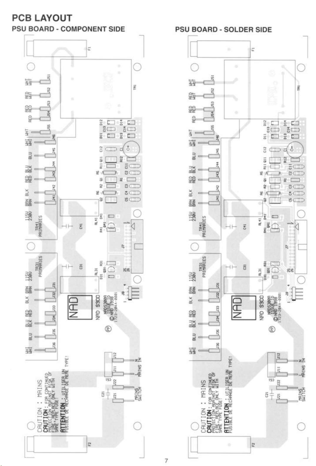
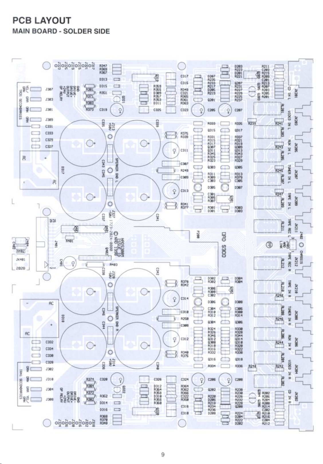
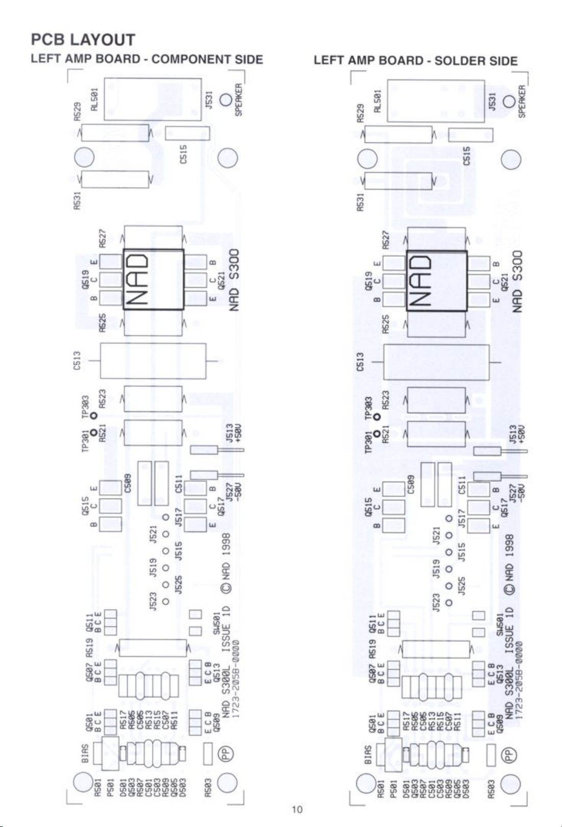
PCB LAYOUT ................................................... 7-12
SCHEMATIC DIAGRAM............................................13-21
IC BLOCK DIAGRAM................................................22
ELECTRICAL PARTS LIST ......................................... 23-28
EXPLODED VIEW.................................................. 29
EXPLODED VIEW PARTS LIST ....................................... 30
PACKING DIAGRAM................................................ 31
SERVICE SAFETY PRECAUTIONS
1. Replacingthe Fuses
CAUTION:
WITH SAME TYPE OF FUSE.
REFERENCE NO. PART NUMBER DESCRIPTION
F1*AH 5100-2510-1C Fuse 250mA 250V Time Lag UL/CSA
F2*AH 5120-0061-0 Fuse 12A 250V Time Lag 6.3x32mm UL/CSA
F1*C 5120-0035-0 Fuse 100mA 250V Time Lag LBCVDE/SEMKO
F2*C 5120-0025-0 Fuse 6.3A 250V Time Lag HBCVDE/SEMKO
NOTE:
*AH : NorthAmerican model only
*C : European model only
2. Safety-checkout (NorthAmerican model only)
FOR CONTINUED PROTECTION AGAINST THE RISK OF FIRE REPLACE ONLY
Parts marked with the symbol are critical with regard to the risk of fire and electric shock.
Replace only withparts recommended by the manufacturer.
Before returning the product to the customer, make leakage current or resistance measurements
to determine that exposed parts are acceptably insulated from the supply circuit.
!
2
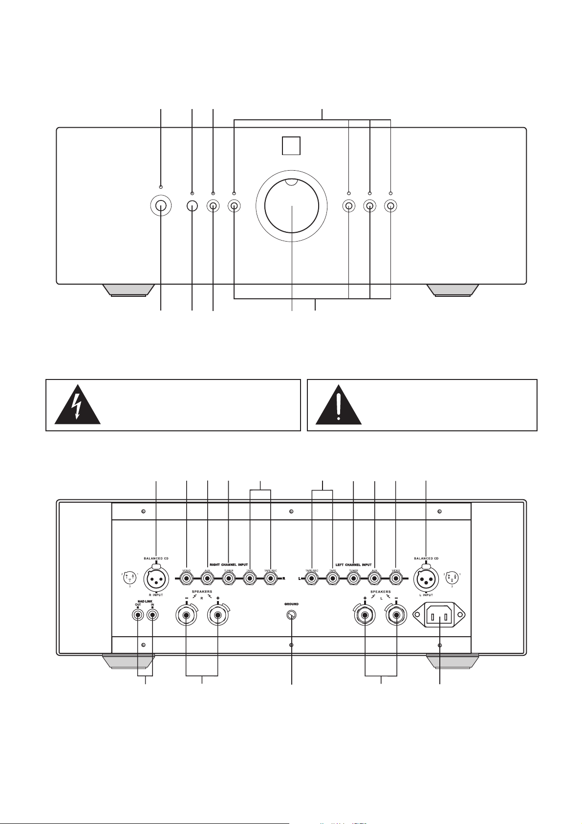
FRONT PANEL / REAR PANEL VIEW
FRONT PANEL CONTROLS
9
12
7
8
TAPE MONITOR TUNERIR CDAUX VIDEO
345
NA
Dual Mono Integrated Amplifier S300
6
D
1. POWER SWITCH 4. VOLUME CONTROL 7. TAPE MONITOR INDICATOR
2. INFRA-RED RECEIVER 5. INPUT SELECTOR 8. INFRA-RED INDICATOR
3. TAPE MONITOR 6. INPUT INDICATOR 9. POWER INDICATOR
The graphic symbol of a lightning flash with an arrow point
within a triangle signifies that there is dangerous voltage
within the unit and it posses a hazard to anyone removing
the cover to gain access to the interior of the unit. Only
qualified service personnel should make such attempt.
The graphic symbol of an exclamation point within
an equilateral triangle warns a user of the device
that it is necessary to refer to the instruction
manual and its warnings for proper operation of
the unit.
REAR PANEL CONNECTIONS
4
12
3
1. RIGHT BALANCED CD INPUT 6. LEFT TAPE INPUT/OUTPUT 11. AC INLET
2. RIGHT VIDEO INPUT 7. LEFT TUNER INPUT 12. LEFT SPEAKER OUTPUT
3. RIGHT AUX INPUT 8. LEFT AUX INPUT 13. GROUND TERMINAL
4. RIGHT TUNER INPUT 9. LEFT VIDEO INPUT 14. RIGHT SPEAKER OUTPUT
5. RIGHT TAPE INPUT/OUTPUT 10. LEFT BALANCED CD INPUT 15. NAD LINK INPUT/OUTPUT
5
131415
6789
12
10
11
3

SPECIFICATIONS
Measured in accordance with EIA Standard RS-490 (IHF-A-202) 1978.
Continuous average power output at 8 100W (20dBW)
(Minimum power per channel, 20Hz-20kHz,
both channels driven, with no more than rated distortion)
Input impedance Single ended 10K
Sensitivity 350mV
(for rated power into 8 )
W
W
Balanced 20K
W
W
Signal-to-Noise ratio (A-weighted) ref. 1W 88dB
Frequency response 20Hz - 20kHz +/-0.1dB
-3dB
DC - 250kHz
Gain tracking error +/-0.1 at maximum
+/-3dB at -60dB level
Damping factor >110
(ref. 8 , 50 Hz)
W
Physical specifications
Dimensions (WxHxD) 450x160 x400mm
Net weight 25.5 kg / 56.1 lbs
4
ALIGNMENT PROCEDURE
IDLE CURRENT ALIGNMENT (no load, no signal)
1. Connect a digital millivoltmeter between TP301 and TP303, and adjust P501 to
obtain a reading of between 30mV and 35mV.
2. Transfer the digital millivoltmeter to TP302 and TP304 and adjust P502 to obtain a
reading of between 30mV and 35mV.
3. Leave power on for at least 5 minutes to allow the idle currents to stabilize.
Re-adjust P501 and P502 as necessary to obtain a reading of between 30mV to
35mV on each channel.
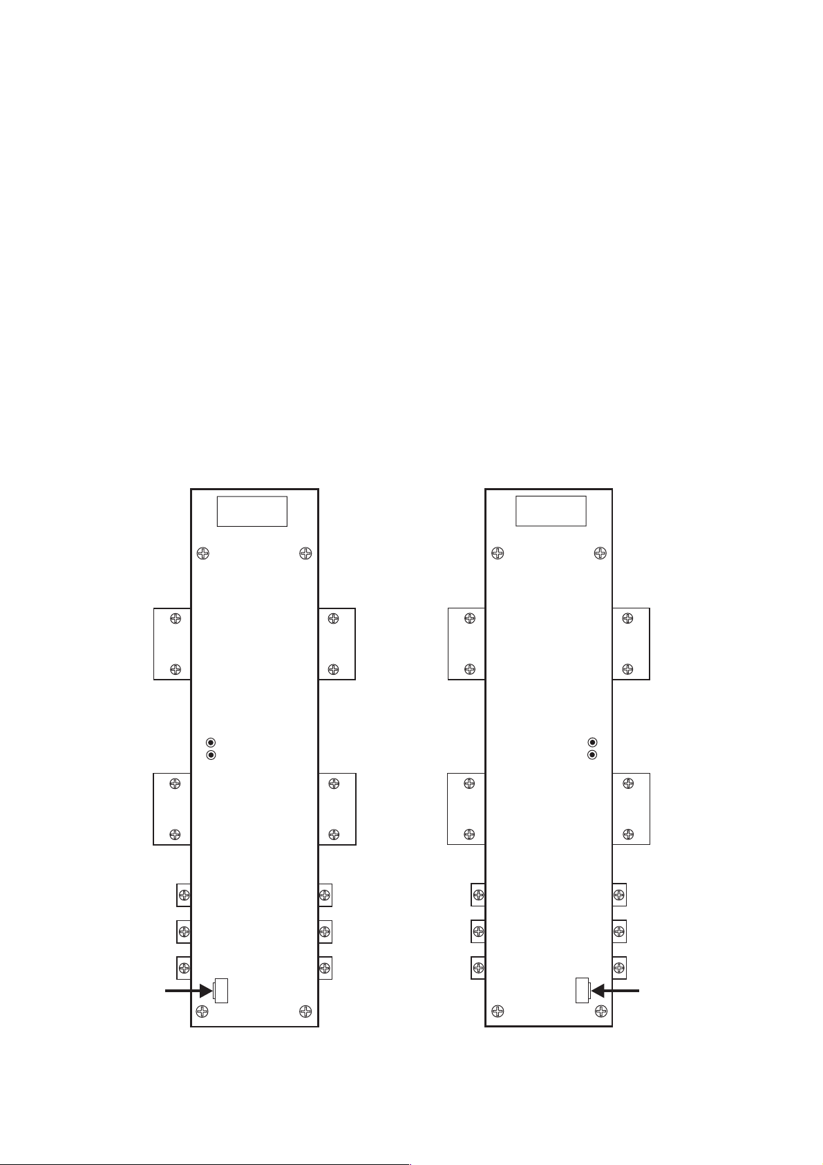
ADJUSTMENT POINTS
LEFT POWER AMP PCB
TP303
TP301
RIGHT POWER AMP PCB
TP304
TP302
ALIGNMENT
TOOL
P501
P502
5
ALIGNMENT
TOOL
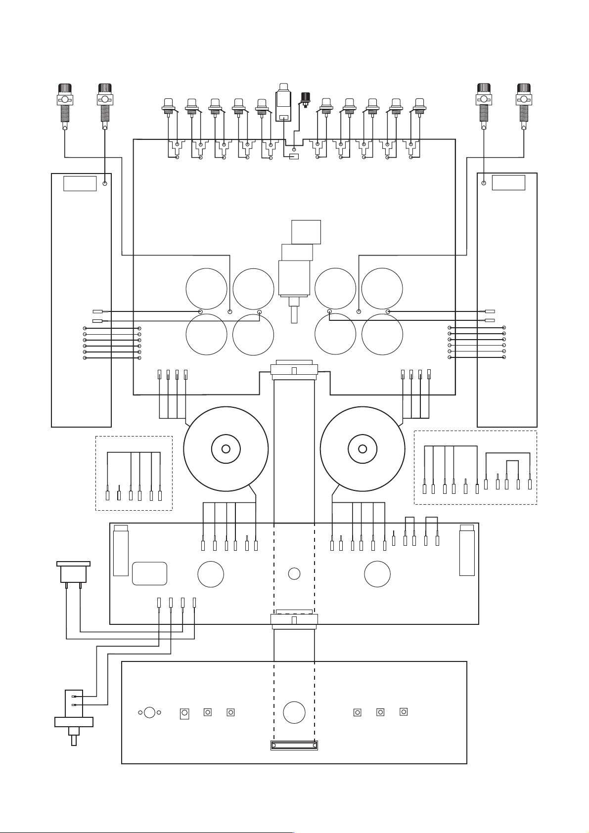
WIRING DIAGRAM
- LEFT +
SPEAKER
TERMINALS
BLACK
J531
RIGHT POWER
AMP BOARD
J517
J521
J515
J519
J525
J523
WHITE
BLUE
WHITE
BLACK
(X6)
J317
J321
J315
J319
J325
J323
J307
RED
BLACK
JK203
J303
+50V
J301
J313
NAD LINK BOARD
BLACK
RED
RED
JK205
JK207
J309
BLACK
SPK
GND L
RED
BLACK
JK209
J404
1
BLACK
RED
GRAY
J403
JK211
MAIN BOARD
J327
-50V
J401
25
26
GROUND TERMINAL
BLACK
RED
RED
SPK
GND R
BLACK
RED
BLACK
BLACK
J402
1
JK212 JK210 JK208 JK206 JK204
J328
-50V
1
2
BLACK
RED
J314
+50V
BLACK
J302
J310
RED
J304
J308
J318
J322
J316
J320
J326
J324
BLUE
WHITE
BLACK
(X6)
+ RIGHT -
SPEAKER
TERMINALS
BLUE
J532
LEFT POWER
AMP BOARD
J518
J522
J516
J520
J526
J524
BLACK
AC INLET
N
BLACK
J36
L
RED
BLACK
PRIMARY - 120V VERSION
WHITE
RED
J35
BLUE
J34
J33
RED
BLACK
J32
J31
J21 J22 J11 J12
YEL/GRN
GRAY
BROWN
TRANSFORMER - LEFT TRANSFORMER - RIGHT
ORANGE
ORANGE
PRIMARY - 230V VERSION
WHITE
J36
BLUE
J35
BLACK
J34
J33
RED
J32
BROWN
J31
J7
25
26
PRIMARY - 230V VERSION
BROWN
J42
J43
J41
1
POWER SUPPLY BOARD
2
FRONT PANEL BOARD
RED
BLACK
J44
BLUE
J45
WHITE
J46
J55
ORANGE
ORANGE
RED
J54
J53
GRAY
BROWN
J41
WHITE
J52
YEL/GRN
PRIMARY - 120V VERSION
RED
BLUE
BLACK
J42
J43
J44
J51
J45
WHITE
J46
J55
J54
WHITE
J53
RED
J52
J51
POWER SWITCH
J102
26
25
2
1
6

 Loading...