


OPERATIONS MANUAL
MODEL: P54K-K2B-K4B
RIDE-ON
VIBRATORY ROLLER
(KUBOTA DIESEL ENGINE)
Revision #0 (12/11/06)
To find the latest revision of this publication, visit our website at: www.multiquip.com
THIS MANUAL MUST ACCOMPANYTHE EQUIPMENT AT ALLTIMES.
Diesel engine exhaust and some of

Foreword:
Practically-oriented development and design and many years of experience in the construction of vibratory trench rollers are your guarantee of a machine complying with the highest standard of quality and reliability.
This operating and maintenance manual encompasses:
• Safety regulations |
• Maintenance instructions |
• A machine description |
• Troubleshooting table |
• Operating instructions |
|
Use of this operating manual will
•simplify the process of familiarization with your machine.
•prevent malfunctions due to operating errors.
Correct observation of the operating instructions will
•increase reliability in on-site operation,
•enhance the service life of the machine,
•reduce repair costs and downtimes.
Rammax GmbH accepts no liability for machine function
•in the event of incorrect handling or operation not in compliance with the prescribed mode of operation and procedures,
•where the machine is used for purposes other than its designated use
(see designated purpose, section 3.1) or for fields of application other than those listed (Section 2.1).
No warranty claims may be asserted in the case of
• Operating errors • Insufficient maintenance and/or • Use of incorrect fuels and operating materials
Remark :
-These instructions were written for the use of machine operators and maintenance staff on the building site.
-The operating and maintenance instructions must always be kept within easy reach of the machine
-Machine operation is only admissible after proper instruction and in observance of this manual.
-The safety regulations outlined on pages 13 - 20, Section 3.0
must be observed under all circumstances. The directives of the German Civil Engineering Professional Association "Safety Regulations for the operation of road rollers and compaction machinery" and the valid accident prevention regulations must
be observed.
For your own safety, and in order not to impair the functional characteristics of the machine, exclusively Rammax spare parts must be used (Section 2.2 Modifications to the machine).
The catalogue of spare parts and the operating instructions are also available in all languages from your Rammax dealer on specification of the machine number.
The warranty and liability conditions contained in the General Terms and Conditions of Rammax are not extended or replaced by the information contained above or below.
Rammax GmbH Metzingen
P54 |
|
K/K2B/K4B |
2 |
Foreword :
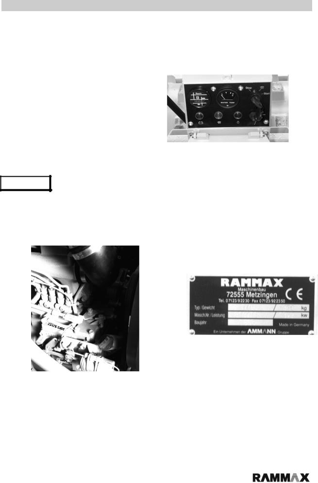
On transfer of the machine, please complete: |
|
...................................................................... |
Fig. 1 |
Machine model (Fig. 3) |
|
...................................................................... |
|
Serial number (Fig. 1) |
|
...................................................................... |
|
Engine type |
|
...................................................................... |
|
Engine number (Fig. 2) |
|
Note :
On machine acceptance, you will receive instruction in the operation and maintenance of the machine by one of our staff or by an authorized dealer. It is vital that you pay particular attention to the instructions relating to safety aspects and hazards which can arise at the machine.
Fig. 2
Fig. 3
P54 |
|
K/K2B/K4B |
3 |

|
Contents : |
|
1.0 Specifications |
|
6 |
1.1 |
Main dimensions |
6 |
1.2 |
Noise and vibration specifications |
9 |
2.0 Description : |
|
10 |
2.1 |
Fields of application |
10 |
2.2 |
Modifications to the machine |
10 |
3.0 Safety Regulations |
|
11 |
3.1 |
Use in accordance with the designated purpose |
12 |
3.2 |
Machine operation |
12 |
3.3 |
Safety remarks in the operating and maintenance instructions |
12 |
3.4 |
Safety signs applied to the machine |
13 |
3.5 |
Loading the machine for transport |
13 |
3.6 |
Towing the machine |
13 |
3.7 |
Checking the rollover bar (ROPS) |
13 |
3.8 |
Starting the machine |
14 |
|
3.8.1 Before starting |
14 |
|
3.8.2 Starting |
14 |
|
3.8.3 Jump starting with jump leads |
14 |
|
3.8.4 Starting in enclosed areas |
14 |
3.9 |
Driving the machine |
15 |
|
3.9.1 Persons in the hazard area |
15 |
|
3.9.2 Driving |
15 |
|
3.9.3 Negotiating uphill and downhill slopes |
15 |
|
3.9.4 Driving in traffic |
15 |
|
3.9.5 Checking the effects of vibration |
16 |
|
3.9.6 Parking the machine |
16 |
|
3.9.7 Parking on uphill and downhill slopes |
16 |
3.10 Refuelling |
16 |
|
3.11 Maintenance work |
17 |
|
|
3.11.1 Work at the hydraulic line |
17 |
|
3.11.2 Changing hydraulic hose lines |
17 |
|
3.11.3 Work on the engine |
18 |
|
3.11.4 Work on the electrical system |
18 |
|
3.11.5 Work on the battery |
18 |
|
3.11.6 Work at the fuel system |
18 |
|
3.11.7 Cleaning work |
18 |
|
3.11.8 After completing maintenance work |
18 |
3.12 Repairs |
18 |
|
4.0 Display and operating elements |
19 |
|
4.1 |
Description of the display and operating elements |
21 |
5.0 Control system |
|
22 |
|
5.1 Pre-commissioning checks |
22 |
|
5.2 Commissioning |
24 |
|
5.3 Start procedure |
24 |
|
5.4 Starting the engine |
25 |
|
5.5 Starting with jump leads |
25 |
|
5.6 Driving operation |
26 |
P54 |
|
K/K2B/K4B |
4 |

|
|
Contents : |
|
|
|
5.7 Vibration |
26 |
|
|
5.8 Operating the pusher blade |
26 |
|
|
5.9 Switching off the machine |
27 |
6.0 Setting the driver's seat |
|
|
27 |
7.0 Loading and transport |
|
|
28 |
8.0 Maintenance |
|
|
30 |
8.1 |
General remarks on maintenance and maintenance work |
30 |
|
8.2 |
Running in regulations |
30 |
|
8.3 |
Maintenance plan |
31 |
|
8.4 |
Checking the oil level in the engine |
32 |
|
8.5 |
Checking the hydraulic oil level / hydraulic filter insert |
32 |
|
8.6 |
Checking the fuel supply |
33 |
|
8.7 |
Exchanging the fuel filter |
33 |
|
8.8 |
Battery |
34 |
|
8.9 |
Tightening the screws |
34 |
|
8.10 |
Checking / cleaning / exchanging the air filter |
35 |
|
8.11 |
Exchanging the engine oil |
36 |
|
8.12 |
Exchanging the hydraulic oil |
36 |
|
|
|
8.12.1 Hydraulic system |
36 |
|
|
8.12.2 Hydraulic oil change |
37 |
8.13 |
Extraction filter / line filter |
37 |
|
8.14 |
Adjusting the stripper |
38 |
|
8.15 |
Radiator |
38 |
|
8.16 |
Changing the tyres |
39 |
|
9.0 Tightening torque for screws with standard metric thread |
39 |
||
10.0 Troubleshooting table |
|
|
41 |
P54 |
5 |
K/K2B/K4B |
|
Specifications :
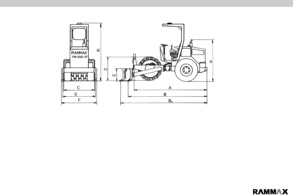
1.0 Specifications
1.1 Main dimensions
__________________________________________________________________________________________________________________________________
_____________
Dimensions in cm : |
A |
B1 |
B |
C |
D |
E |
F |
G |
H1 |
K |
P54-K: |
340 |
---- |
---- |
138 |
89 |
--- |
---- |
148 |
180 |
226,5 |
P54-K2B: |
340 |
---- |
360 |
138 |
89 |
36 |
160 |
148 |
180 |
226,5 |
P54-K4B: |
340 |
375 |
---- |
138 |
89 |
36 |
160 |
148 |
180 |
226,5 |
P54 |
6 |
K/K2B/K4B

Specifications :
Weights : |
P54 K |
P54 K2B |
P54 K4B |
Intrinsic weight : |
3100 kg |
3300 kg |
3400 kg |
Operational weight : |
3340 kg |
3560 kg |
3640 kg |
Central axle load : |
1500 kg |
3100 kg |
1650 kg |
Axle load front/back : |
1600/1400 kg |
1800/1400 kg |
1900/1400 kg |
Driving characteristics : |
|
|
|
Driving speed |
|
|
|
Forward/reverse : |
|
|
|
With vibration : |
0 - 4 kph |
0 - 4 kph |
0 - 4 kph |
Without vibration : |
0 - 4 kph |
0 - 4 kph |
0 - 4 kph |
Maximum climbing ability : |
|
|
|
With vibration : |
45 % |
45 % |
45 % |
Without vibration : |
45 % |
45 % |
45 % |
Max. admissible incline |
45 % |
45 % |
45 % |
Drive system/power unit: |
|
|
|
Engine manufacturer : |
Kubota |
Kubota |
Kubota |
Type : |
V-1903 |
V-1903 |
V-1903 |
Cooling : |
water cooling |
water cooling |
water cooling |
No. of cylinders : |
4 |
4 |
4 |
Output : |
27 kW (38 hp) |
27 kW (38 hp) |
27 KW (38 hp) |
Speed : |
2930 rpm |
2930 rpm |
2930 rpm |
Battery : |
12V 45Ah |
12V 45Ah |
12V 45Ah |
Drive mode : |
hydrostatic |
hydrostatic |
hydrostatic |
Driven axles : |
front/rear |
front/rear |
front/rear |
Electrical equipment : |
12 V |
12 V |
12 V |
Brakes : |
|
|
|
Service brake : |
hydrostatic |
hydrostatic |
hydrostatic |
Parking brake : |
mechanical |
mechanical |
mechanical |
Steering : |
|
|
|
Steering mode : |
articulation |
articulation |
articulation |
Steering actuation : |
hydrostatic |
hydrostatic |
hydrostatic |
Steering angle : |
± 35° |
± 35° |
± 35° |
Suspension angle : |
± 15° |
± 15° |
± 15° |
Vibration system : |
|
|
|
Drive mode : |
hydrostatic |
hydrostatic |
hydrostatic |
Frequency |
41 Hz |
41 Hz |
41 Hz |
Amplitude |
1.7 mm |
1.7 mm |
1.7 mm |
Centrifugal force : |
87 kN (8500 kp) |
87 kN (8500 kp) |
87 kN (8500 kp) |
P54 |
7 |
K/K2B/K4B

|
|
|
Specifications : |
Pusher blade : |
|
|
|
Pusher blade height : |
|
360 mm |
360 mm |
Pusher blade width : |
|
1600 mm |
1600 mm |
Pusher blade tilt angle : |
|
± 15° |
± 15° |
Filling quantities / tank capacities : |
|
|
|
Fuel : |
50 l |
50 l |
50 l |
Hydraulic oil : |
200 l |
200 l |
200 l |
Tyres : |
|
|
|
Number of tyres : |
2 |
2 |
2 |
Tyre size : |
12,5/80 - 18 AS |
12,5/80 - 18 AS |
12,5/80 - 18 AS |
Tyre pressure : |
3.5 bar |
3.5 bar |
3.5 bar |
P54 |
8 |
K/K2B/K4B

Specifications :
1.2 Noise and vibration specifications
The noise and vibration specifications listed below in accordance with the EC Machine Directive in the draft (92/68/EEC) were determined under operating conditions typical for the machinery in question with vibration over a specified travel surface.
In operational application, deviating values may result depending on the prevailing operating conditions.
Noise specification
The noise emission specification stipulated in accordance with Annex 1, Section 1.7.4.f of the EC Machine Directive is as follows
- Sound pressure level at the operator position : LpA = 91.5 dB(A)
- Sound power level : |
LWA = 106.7 dB(A) |
These noise emission values were determined in accordance with ISO 6081 for the sound pressure level (LpA) and ISO 3744, DIN 45635, for the sound power level (LWA).
Vibration specification
The vibration specifications stipulated in accordance with Annex 1, Section 2.2 / 3.6.3. a of the EC Machine Directive are as follows :
Subject to modifications
Rammax P54
P54 |
9 |
K/K2B/K4B
Description:
2.0 Description
Description :
Many years of experience, continuous further development and the latest technological innovations in the construction of vibratory trench rollers have culminated in one of the highest-performance machines of the P54 series. All the models of the P54 series are characterized by a high degree of operating convenience, a hardwearing compact design and outstanding reliability in operation. The RAMMAX P54 is a self-propelling, centrepivot steered vibratory roller which can be optionally equipped with a sheeps foot facing or a pusher blade. The P54 can also be equipped with a tilt device which permits an even subsoil to be created with the pusher blade even on inclined surfaces.
For all machine models of the P54 series, operation of the pusher blade is performed using a single-hand lever. Travel drive, vibration, steering and braking operations are hydraulically powered. The facing and wheels are independently driven and infinitely variable using two control pumps. Travel drive is actuated by two pedals.
This drive system permits an outstanding climbing ability (depending on soil conditions 45%)
_____________________________________________________________________________________
2.1 Fields of application :
Vibratory roller P54 is designed especially for levelling and compaction work. The fields of application for this modern vibratory roller include wet conditions, clay soils encountered in canal building, pipelaying work, road substructure work and backfill work.
_____________________________________________________________________________________
2.2 Modifications to the machine :
For reasons of safety, users are prohibited from making their own modifications or conversions to the machine. This machine must only be equipped using original spare parts designed for use with the machine and in compliance with the requirements of the manufacturer. The installation or utilization of special equipment or special parts can impair driving safety.
The manufacturer is exonerated of any liability for damage caused as a result of the use of non-original parts or special equipment.
_____________________________________________________________________________________
P54 |
10 |
K/K2B/K4B

3.0 Safety regulations
|
|
P54 |
11 |
K/K2B/K4B

Safety remarks :
3.1 Use in accordance with the designated purpose :
Vibratory roller P54 is constructed in accordance with the state of the art and with accepted rules of operating safety. However, its use can still give rise to hazardous situations which constitute a danger to life and limb for the operator or for third parties or which can lead to impairment of the machine or damage to other property if
•it is used for any other than its designated purpose
•it is modified or conversion work carried out by unqualified persons
•the safety remarks are not observed
•it is not operated or maintained by suitably qualified personnel.
The P54 must only be operated when in a technically flawless condition and in accordance with its designated purpose with sufficient awareness of safety aspects and potential hazards and in strict observance of the operating instructions. In particular malfunctions which could detract from the safety of the equipment must be remedied without delay.
When operating the roller, adherence to the valid accident prevention regulations and the generally accepted rules of safety, as well as country-specific regulations is assumed.
The point "Fields of application" (Section 2.1) outlines the designated purpose for which the P54 is exclusively intended. Any other or further reaching use is deemed to be not in accordance with the designated purpose. The manufacturer/supplier accepts no liability for any damage arising as a result of such incorrect use. All risk arising rests solely with the user.
_____________________________________________________________________________________
3.2 Machine operation :
Only suitably qualified and designated persons who have received the appropriate training, and who are over 18 may drive and operate the machine. Fields of responsibility during operation must be clearly defined and adhered to.
All persons entrusted with operation, maintenance or repair of the machine must read and adhere to the safety regulations. Where appropriate, this must be confirmed by the user's company by means of a signature by the person or persons concerned.
Persons acting under the influence of drugs, medicines or alcohol may not operate, maintain or repair the machine.
Maintenance and repair call for special knowledge and may only be performed by suitably trained and qualified personnel.
_____________________________________________________________________________________
3.3 Safety remarks in the operating and maintenance instructions:
Danger |
This warning sign is an indication of possible danger of personal |
|
injury. |
Note :
This warning sign is an indication of possible impairment to the machine or parts of the equipment.
Remark :
P54
K/K2B/K4B
These parts of the instructions provide technical information intended to ensure optimum economy and efficient use of the machine.
12
 Loading...