


PARTS AND OPERATION MANUAL
 VR36HA
  VIBRATORY ROLLER
© COPYRIGHT 2000, MULTIQUIP INC.
Revision #6 (06/13/06)
MULTIQUIP INC. |
PARTS DEPARTMENT: |
18910 WILMINGTON AVE. |
800-427-1244 |
CARSON, CALIFORNIA 90746 |
FAX: 800-672-7877 |
310-537-3700 |
SERVICE DEPARTMENT/TECHNICAL ASSISTANCE: |
800-421-1244 |
800-478-1244 |
FAX:310-537-3927 |
FAX:310-631-5032 |
 E-mail:mq@multiquip.com • www:multiquip.com
Atlanta • Boise • Dallas • Houston • Newark Montreal, Canada • Manchester, UK
Rio De Janiero, Brazil • Guadalajara, Mexico


HERE'S HOW TO GET HELP
PLEASE HAVE THE MODEL AND SERIAL NUMBER ON-HAND WHEN CALLING
PARTS DEPARTMENT
800-427-1244 or 310-537-3700 FAX: 800-672-7877 or 310-637-3284
SERVICE DEPARTMENT/TECHNICAL ASSISTANCE
800-478-1244 or 310-537-3700 FAX: 310- 537-4259
WARRANTY DEPARTMENT
888-661-4279, or 310-661-4279 FAX: 310- 537-1173
MAIN
800-421-1244 or 310-537-3700 FAX: 310-537-3927
VR-36HA - VIBRATORY ROLLER — PARTS & OPERATION MANUAL — REV. 6 (06/13/06) — PAGE 3

Here's How To Get Help .......................................... |
2 |
Table Of Contents ................................................... |
3 |
Parts Ordering Procedures ..................................... |
4 |
Rules For Safe Operation ................................... |
5-6 |
Operations .......................................................... |
7-8 |
MULTIQUIP — VR36HA VIBRATORY ROLLER
Explanation Of Codes In Remarks Column .......... |
10 |
Suggested Spare Parts ......................................... |
11 |
Engine Cover & Articulated Joint ..................... |
12-13 |
Hydraulic Oil Filters .......................................... |
14-15 |
Engine Coupler ................................................ |
16-17 |
Hydraulic Drive Pumps..................................... |
18-19 |
Hydraulic fitting & Exhaust Systems ................ |
20-21 |
Adapters, Steel Lines & Hoses ........................ |
22-23 |
Adapters, Steel Lines & Hoses ........................ |
24-25 |
Front Drum & Exciter........................................ |
26-27 |
Rear Drum ....................................................... |
28-29 |
Sheet Metal, Fuel & Water Tanks & Seat ......... |
30-31 |
Steering Cylinder, Rear Frame Components & |
|
Throttle Control ................................................ |
32-33 |
Steering Column & Switches............................ |
34-35 |
Scrapers ........................................................... |
36-37 |
Battery, Rear Water Pipes ................................ |
38-39 |
Transmission & Brake Control.......................... |
40-41 |
Brake Control Compnents ............................... |
42-43 |
Water System ................................................... |
44-45 |
Hydraulic Manifold ........................................... |
46-47 |
Hoses & Electrical System ............................... |
48-49 |
Drive Motor, Tubes, Hoses, Fuel Pump ........... |
50-51 |
SERVICE INFORMATION |
|
Maintenance (1.0) ................................................. |
52 |
Engine Lubrication (1.1)........................................ |
52 |
Center Joint (articulation) (1.2)............................. |
52 |
Rear Drum (1.3) .................................................... |
52 |
Vibrator Oil (1.4) ................................................... |
52 |
NOTE: Specification and part number are subject to change without notice.
TABLE OF CONTENTS |
|
Hydraulic System (1.5).......................................... |
53 |
Changing Hydraulic Oil & Filters (1.6) .................. |
53 |
Scraper Bars & Cocoa Mats (1.7) ......................... |
53 |
Towing Valve (1.8) ................................................. |
53 |
Hydraulic System (2.0).......................................... |
53 |
General — Hydraulic Flow Diagram (2.1)............. |
53 |
Drum Drives (2.2) ................................................. |
54 |
Vibration & Streering (2.3) .................................... |
54 |
Back Pressure Valve (2.4) ..................................... |
54 |
Towing Valve (2.5) ................................................. |
54 |
Testing Hydraulic Pressure (2.6)........................... |
54 |
Hydraulic Diagram ................................................ |
55 |
A. Drive Circuit Pressure ....................................... |
56 |
B. Adjusting Drive Relief Valves............................. |
57 |
C. Vibration Circuit Pressure ................................. |
57 |
D. Steering Circuit Pressure .................................. |
57 |
Removing & Replacing Hydraulic |
|
Pump Assembly (2.7)............................................ |
57 |
Removing & Replacing Vibration/Steering Pumps & |
|
Hydraulic Schematic (2.8) ..................................... |
58 |
Drum & Main Frame (3.0) ..................................... |
59 |
Removing Front Drum (3.1) .................................. |
59 |
Front Drum Disassembly (3.2) .............................. |
59 |
Front Drum Assembly (3.3) ................................... |
59 |
Vibrator Assembly Removal (3.4) ......................... |
60 |
Vibrator Assembly Installation (3.5) ...................... |
60 |
Vibrator Disassembly (3.6) ................................... |
60 |
Vibrator Assembly (3.7) ........................................ |
60 |
Installation Front Drum (3.8) ................................. |
61 |
Drive Motor Removal (3.9) ................................... |
61 |
Drive Motor Installation (3.10) .............................. |
61 |
Rear Drum Removal (3.11) .................................. |
61 |
Rear Drum Installation (3.12) ............................... |
62 |
Alternator/Regulator (4.0) ..................................... |
62 |
Neutral Safety Switch (4.1) ................................... |
62 |
Vibration Solenoid (4.2) ........................................ |
62 |
Ignition Switch (4.3) .............................................. |
63 |
Starter Solenoid (4.4) ........................................... |
63 |
Fuses (4.5)............................................................ |
63 |
Electrical Schematic (4.6) ..................................... |
63 |
Terms and Conditions Of Sale — Parts ................ |
64 |
PAGE 4 — VR-36HA • VIBRATORY ROLLER — PARTS & OPERATION MANUAL — REV. 6 (06/13/06)
PARTS ORDERING PROCEDURES
■Dealer account number
■Dealer name and address
■Shipping address (if different than billing address)
■Return fax number
■Applicable model number
■Quantity, part number and description of each part
■Specify preferred method of shipment:
•UPS Ground
•UPS Second Day or Third Day*
•UPS Next Day*
•Federal Express Priority One (please provide us with your Federal Express account number)*
•Airborne Express*
•Truck or parcel post
*Normally shipped the same day the order is received, if prior to 2PM west coast time.
Earn Extra Discounts when you order by FAX!
All parts orders which include complete part numbers and are received by fax qualify for the following extra discounts:
Number of |
|
line items ordered |
Additional Discount |
1-9 items |
3% |
10+ items** |
5% |
Get special freight allowances when you order 10 or more line items via FAX!**
■UPS Ground Service at no charge for freight
■PS Third Day Service at one-half of actual freight cost
No other allowances on freight shipped by any other carrier.
**Common nuts, bolts and washers (all items under $1.00 list price) do not count towards the 10+ line items.
*DISCOUNTS ARE SUBJECT TO CHANGE*
Fax order discount and UPS special programs revised June 1, 1995
Extra |
Fax |
Discount |
||||
|
|
USA |
||||
|
|
|
||||
for |
Domestic |
|
||||
Dealers |
Only |
|||||
|
||||||
|
|
|
||||
Now! Direct TOLL-FREE access to our Parts Department!
Toll-free nationwide:
800-421-1244
Toll-free FAX:
800/6-PARTS-7 • 800-672-7877
VR-36HA • VIBRATORY ROLLER — PARTS & OPERATION MANUAL — REV. 6 (06/13/06) — PAGE 5

Read and understand this manual before attempting to operate the machine.
The VR-36H roller has been designed for asphalt application and compaction of granular soils used in site preparation. Use the machine only for the purpose intended and by experienced personnel who understand this operating manual and all safety decals.
Keep this manual with the machine and refer to it frequently.
DANGER! Indicates extreme care should be taken to prevent personal injury during operation, inspection, maintenance and service.
CAUTION! Indicates when special observation is needed during operation and maintenance of this machine.
SAFETY RULES
■Completely familiarize yourself with the operation and safety of this machine BEFORE USE.
■DO NOT remove or modify any parts of the machine. Doing so may result in the warranty becoming invalid.
■DO NOT use the machine for any purpose other than that which it is intended.
■Always wear proper safety equipment: hard hat
safety glasses work clothes safety shoes
protective gloves
respirator in dusty environments
DANGER! Stay Clear of turning points of machine. This is a pinch point. Never place yourself or allow anyone else to stand near the unit while the engine is running.
■Start the unit only when seated in the operator’s position. (see starting instructions)
RULES FOR SAFETY OPERATION
■Whenever possible, always stop the unit on a stable, level and hard surface. If the machine must be stopped on an incline; before leaving the operator’s seat, secure the parking brake and stop the engine; then chock both the front and rear drums securely. Always remove the ignition key to prevent unauthorized personnel from operating the machine.
DANGER! Exhaust gasses are extremely dangerous and cause death. Operate the machine only in well ventilated areas.
■If malfunction occurs in the travel lever mechanism, speed and direction will be impossible to control. Immediately stop the
■In the event of hydraulic hose or pipe failure, promptly return the travel lever to the “neutral” position, stop the engine and set the parking brake.
■If the steering system operates improperly, immediately stop the engine and apply the parking brake.
■When malfunctions occur, always remove the ignition key and place a “DO NOT OPERATE” sign in the operator’s seat.
INSPECTION PRIORTO STARTING
DANGER! Perform inspections only with the machine parked on a stable, level and hard surface. Never inspect the unit with the engine running. Inspections should only be performed by trained and qualified personnel.
CAUTION! Perform the following checks before each operation of the machine and only with the engine STOPPED!
■Check hydraulic oil, engine oil, and fuel levels and for leakage.
■Check all hydraulic components and fittings for wear.
■Insure smooth movement of the travel lever, throttle and parking brake.
■Check all fasteners (bolts & nuts) for tightness.
PAGE 6 — VR-36HA • VIBRATORY ROLLER — PARTS & OPERATION MANUAL — REV. 6 (06/13/06)

STARTINGTHE ENGINE
DANGER! Always keep the operator’s area clean and free from debris, dirt, oil, grease, mud, asphalt or anything else that may become a hazard to free movement of the operator.
■Make sure no unauthorized personnel are near the machine before attempting to start the unit.
DANGER! Start and operate the unit only from the operator’s position.
■Always use seat belts when provided.
■Adjust the seat to obtain the most comfortable position.
■Place the travel lever in the “neutral” position BEFORE attempting to start the unit.
■Make sure that the “vibrator” switch is in the “OFF” position.
■Pull the “choke” knob to full choke (see engine operating manual).
■Turn the key to the start position to the right of the “ON” position. (The ignition switch is spring loaded to prevent the starter from being constantly engaged.)
■As soon as the engine has started, release the ignition key.
■Adjust the choke as required until the engine runs smoothly.
CAUTION! Do not operate the starter switch when the engine running.
RULES FOR SAFETY OPERATION
INSPECTION (After Start-Up)
■Run the engine at an idle 3 to 5 minutes. In colder climates, longer warm periods may be necessary. Sufficiently warming the engine allows all lubricants to reach the proper operating temperature.
CAUTION! Do not leave the operator’s position while the engine is running.
Test the steering for proper operation - left to right.
DANGER! Do not attempt to check the steering function if anyone is near the unit or in the way of the front or rear drums.
■While seated in the operator’s seat and with the engine running, check that the hydraulic oil level indicator registers in the “operation” zone.
■Check for abnormal noise, odor, exhaust color or other sign that may be out of the ordinary.
ROPS — Roll Over Protection System
It is strongly suggested that ROPS and seat belts be installed on this machine to protect the operator against the unlikely event of a rollover.
The ROPS are sold as a optional accessory item and may be ordered by calling:
Multiquip Sales • 800-421-1244 - P/N VR36ROPS
The following is a few examples of hazardous conditions of when ROPS must be used:
1)When working on slopes or near open trenches
2)Hollow spaces or rocks that might be below the surface.
3)Sharp steering movements.
4)Surfaces that may be slippery or objects in the roller path.
VR-36HA • VIBRATORY ROLLER — PARTS & OPERATION MANUAL — REV. 6 (06/13/06) — PAGE 7

OPERATION
By moving the travel lever forward or backward, the machine will travel in either forward or reverse.The speed in which movement of this lever is made is directly related to the amount of pressure that is applied to the travel lever in each direction.Travel speed is infinitely variable from 0 to 4.8 mph.
DANGER! Before operating the roller, make sure that personnel and obstacles are free from the roller’s path. Serious injury or death can result!
CAUTION! Allow the roller to come to a complete stop before changing the direction of travel. Changing directions before the roller comes to a complete stop will result in excessive force being applied to the transmission and drive system which will reduce overall service life.
COMPACTION
In order to apply vibration to the surface, the vibrator switch must be in the “ON” position. If the vibration appears to be weak or slow, allow the machine to warm-up thoroughly, and check the hydraulic oil level. Add hydraulic oil if necessary.
CAUTION! Do not allow the roller to operate on cured concrete or other hard surface while the vibrator is “ON”.
WATER SYSTEM
The built-in water sprinkling system is designed to apply sufficient quantities of water to the surface of the rollers. This method prevents fresh asphalt from sticking to the drums while the rolling operation is taking place.
The water system is fully adjustable from the operator’s position by adjusting the two water valves. The front valve controls the water supply to the front drum, and the rear valve controls water to the rear drum.
Each roller is equipped with drum scrapers that are lined with cocoa mats.These mats must be wetted before operation either by the water supply system or other water source.
REFUELING
DANGER! Do not attempt to refuel the engine while running! Spilled gasoline can cause fire or explosion and can cause serious injury or even death! Do not smoke or allow sparks or open flame near the machine at any time - especially when refueling. Clean the engine of any spilled fuel BEFORE restarting.
VR-36HA — OPERATIONS
PARKING BRAKE
CAUTION! Always apply the parking brake when the roller is stopped. Do not operate the machine with the parking brake in the “SET” position. Severe brake wear can result.
ENGINE SHUT-DOWN
DANGER! Do not leave the operator’s seat while the engine is running.
CAUTION! Should stopping the unit be unavoidable on a slope or grade, stop the engine, set the parking brake and place chocks in the front and rear of each drum.
■Place the travel lever in the “neutral” position.
■Return the throttle lever to the idle position.
■Turn the vibration switch to the “OFF” position.
■Set the parking brake
■Allow the engine to idle for 3 to 5 minutes prior to stopping to allow proper cool-down period.
■Stop the engine and remove the ignition key.
LOADING ANDTRANSPORTING
DANGER! ALWAYS LOAD AND UNLOAD THE ROLLER ON LEVEL, HARD GROUND OR PAVEMENT. Serious injury or death can result from improper loading, lifting or unloading. Use caution!
■When driving the roller onto a transporting vehicle or trailer
■Use ramps or other suitable material of sufficient strength to support the roller.
■Remove mud, oil, ice, snow or any other slippery materials from the ramps and bed of the vehicle to avoid accidents.
■After loading, apply the parking brake, lock the frame with the locking bar that is provided.
■Use chain and binders or other suitable means to firmly secure the load before attempting to move the vehicle.
■Lifting the roller onto a transporting vehicle or trailer
■Only use the lifting points for the roller that are clearly marked as “lifting point”.
DANGER! Do not allow personnel under or near any suspended machine. Serious injury or death may result.
PAGE 8 — VR-36HA • VIBRATORY ROLLER — PARTS & OPERATION MANUAL — REV. 6 (06/13/06)

■Remove mud, oil, ice, snow or any other slippery materials from the ramps and bed of the vehicle to avoid accidents.
■After loading, apply the parking brake, lock the frame with the locking bar that is provided.
■Use chain and binders or other suitable means to firmly secure the load before attempting to move the vehicle.
BATTERY INFORMATION
DANGER! Lead acid batteries contain sulfuric acid which will damage eyes, skin and clothing upon contact. Always wear proper safety eye protection, rubber gloves and other safety clothing. Should acid contact the eyes, flush immediately with clean water and get prompt medical attention. If acid comes in contact with skin, wash immediately with clean water and get prompt medical attention.
DANGER! Avoid fire and open flame near batteries.Battery acids are extremely flammable and explosion can result.
■Clean and inspect battery terminals regularly.
■Non-use of machine will result in reduced battery charge level and will damage the plates which reduces the battery life.
■Keep battery caps tightly fastened at all times.
■Add distilled water as needed
■Proper sequence must be observed during installation and removal of batteries:
■Removal - Disconnect the negative (ground) terminal first, then the positive terminal.
■Installation - Install the Positive terminal first, then the negative (ground) terminal.
DANGER! Never allow the negative and positive cables to come in contact with each other.Serious injury could result.
VR-36HA — OPERATIONS
SERVICE AND INSPECTION
Performing all periodic inspections and service work on a timely basis will result in increased performance, productivity and reduced maintenance costs.
When the roller is used in severe, unusually dusty or dirty, or extremely humid or hot environments, it will be necessary to perform routine service and inspections more frequently.
DANGER! Always operate the machine in a well ventilated area. Exhaust gasses are dangerous and cause injury or death. Never operate this or any other machine within an enclosed space.
SERVICE INSTRUCTIONS CHART
Engine Speed
Exciter Speed
Exciter Lubrication
Grease
Hydraulic Oil
Hydraulic Filter
Engine Lubrication/
Service
CAUTION! Running the machine without sufficient hydraulic oil will result in extreme damage to the unit’s hydraulic system.
VR-36HA • VIBRATORY ROLLER — PARTS & OPERATION MANUAL — REV. 6 (06/13/06) — PAGE 9

VR-36HA — EXPLANATION OF CODE IN REMARKS COLUMN
How to read the marks and remarks used in this parts book.
Section 1: Items Found In the “Remarks” Column
Serial Numbers-Where indicated, this indicates a serial number range (inclusive) where a particular part is used.
Model Number-Where indicated, this shows that the corresponding part is utilized only with this specific model number or model number variant.
Section 2: Items Found In the “Remarks” Column
Serial Numbers-Where indicated, this indicates a serial number range (inclusive) where a particular part is used.
Model Number-Where indicated, this shows that the corresponding part is utilized only with this specific model number or model number variant.
Section 3: Items Found In the “Items Number” Column
All parts with same symbol in the number column, *, #, +, %, or ■, belong to the same assembly or kit.
Note: If more than one of the same reference number is listed, the last one listed indicates newest (or latest) part available.
NOTE
If more than one of the same reference number is listed, the last one listed indicates newest (or latest) part available.
NOTE
The contents of this catalog are subject to change without notice.
PAGE 10 — VR-36HA • VIBRATORY ROLLER — PARTS & OPERATION MANUAL — REV. 6 (06/13/06)
VR-36HA — SUGGESTED SPARE PARTS
VR36HA
|
|
1 Unit |
Qty.. |
P/N ................... |
Description |
2 ..... |
508667 ............. |
HYDRAULIC FILTER CART. |
3 ..... |
506141 ............. |
RUBBER SHOCK MOUNTS |
6 ..... |
508433 ............. |
RUBBER SHOCK MOUNTS |
1 ..... |
506097 ............. |
FWD./REV.CABLE |
1 ..... |
510229 ............. |
ENG THROTTLE CABLE |
1 ..... |
506239 ............. |
ENGINE CHOKE CABLE |
2 ..... |
503735 ............. |
FLANGE BEARING |
4 ..... |
352431090 ....... |
INLINE FUEL FILTER |
1 ..... |
9807956846 ..... |
SPARK PLUG |
1 ..... |
17010ZJ1000 ... |
ELEMENT SET |
1 ..... |
506267K ........... |
KEY |
NOTE
Part numbers on this Suggested Spare Parts List may supercede/ replace the P/N shown in the text pages of this book.
VR-36HA • VIBRATORY ROLLER — PARTS & OPERATION MANUAL — REV. 6 (06/13/06) — PAGE 11
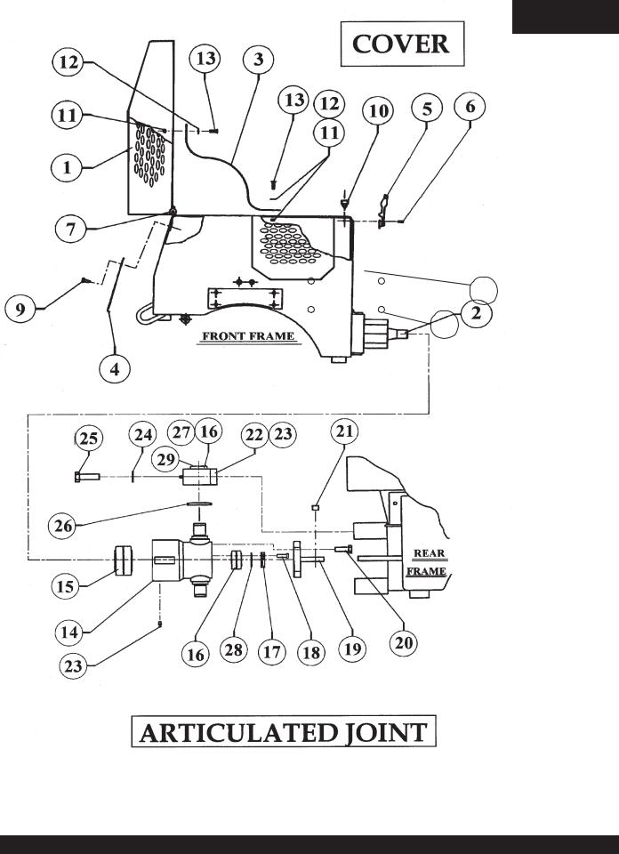
VR-36HA — ENGINE COVER & ARTICULATED JOINT
30
31
PAGE 12 — VR-36HA • VIBRATORY ROLLER — PARTS & OPERATION MANUAL — REV. 6 (06/13/06)

VR-36HA — ENGINE COVER & ARTICULATED JOINT
MODEL VR-36H
ENGINE COVER & ARTICULATED JOINT
NO |
PART NO |
PART NAME |
QTY. |
SERIAL NO. |
1 |
506100 |
COVER ........................................................................ |
1 ........................... |
S/N 960601 TO 970630 |
1 |
510074 |
COVER ........................................................................ |
1 ........................... |
S/N 970701 & UP |
2 |
506103 |
ARTICULATED SHAFT |
1 |
|
3 |
506095 |
CABLE |
1 |
|
4 |
506101 |
FRONT COVER |
1 |
|
5 |
504544 |
LATCH ASSEMBLY |
2 |
|
7 |
491687 |
KING PIN |
2 |
|
9 |
506158 |
HEX. HEAD SCREWS 5/16" NC x ¾" G5 |
7 |
|
10 |
490937 |
RUBBER BUMPER |
2 |
|
11 |
492582 |
LOCK NUT 5/16" NC |
2 |
|
12 |
492597 |
FLAT WASHER 5/16" |
2 |
|
13 |
506176 |
FLAT HEAD SOCKET S. 5/16 NC x 1" G5 |
2 |
|
14 |
506102 |
ARTICULATED BODY |
1 |
|
15 |
506164 |
BEARING |
1 |
|
16 |
506165 |
BEARING |
3 |
|
17 |
506104 |
RETAINER |
1 |
|
18 |
492269 |
SOCKET HEAD SCREW 5/16" NF x ¾" G5 |
3 |
|
19 |
506105 |
PIVOT |
1 |
|
20 |
506172 |
HEX. HEAD SCREW ½" NC x 1, 3/8" G5 |
4 |
|
21 |
506124 |
BUSHING |
2 |
|
22 |
506107 |
PILLOW BLOCK |
2 |
|
23 |
491705 |
GREASE FITTING ¼" NF |
4 |
|
24 |
506109 |
FLAT WASHER |
4 |
|
25 |
503982 |
HEX. HEAD SCREW 5/8" NC x 2" G5 |
4 |
|
26 |
506160 |
SHAFT SEAL |
2 |
|
27 |
506110 |
PLUG |
2 |
|
28 |
506166 |
SHIM |
3 |
|
29 |
506110 |
DUST CAP |
2 |
|
30 |
510292 |
ACCESS COVER ......................................................... |
1 ........................... |
S/N 970701 & UP |
31 |
506176 |
BOLTS ......................................................................... |
4 ........................... |
S/N 970701 & UP |
WHEN ORDERING PARTS, ALWAYS GIVE MODEL NUMBER AND SERIAL NUMBER OF UNIT.
VR-36HA • VIBRATORY ROLLER — PARTS & OPERATION MANUAL — REV. 6 (06/13/06) — PAGE 13
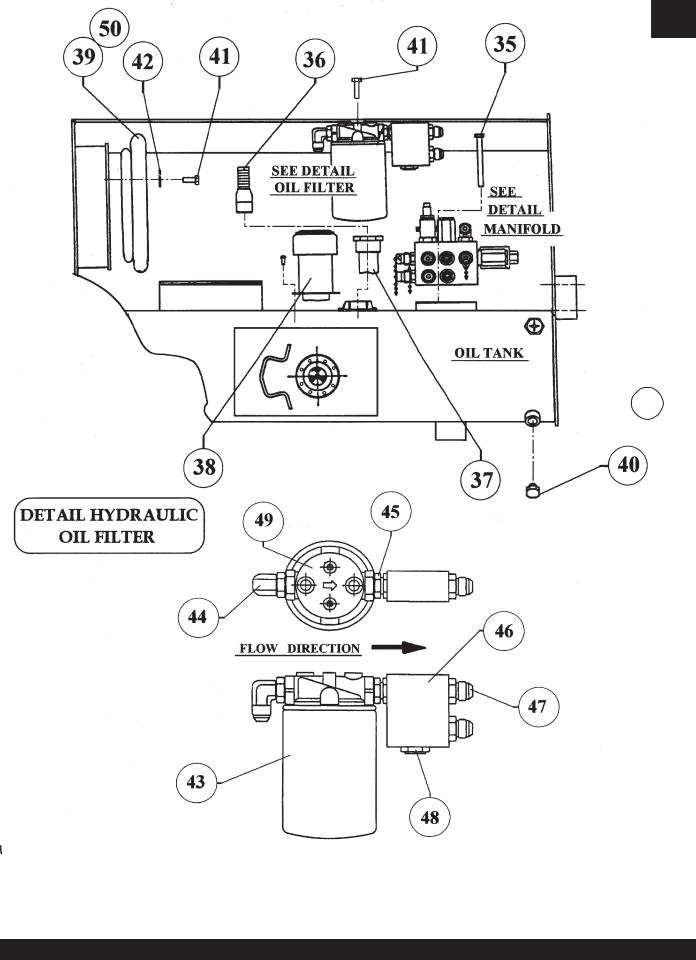
VR-36HA — HYDRAULIC OIL FILTERS
 51
51
PAGE 14 — VR-36HA • VIBRATORY ROLLER — PARTS & OPERATION MANUAL — REV. 6 (06/13/06)

VR-36HA — HYDRAULIC OIL FILTERS
MODEL VR-36H
HYDRAULIC OIL FILTER
NO |
PART NO |
PART NAME |
QTY. |
SERIAL NO. |
35 |
508814 |
HEX. HEAD SCREW 5/16" NC x 3, ¼" G5 |
2 |
|
36 |
506218 |
FITTING INLET |
1 |
|
37 |
506221 |
SUCTION FILTER |
1 |
|
38 |
507278 |
CAP |
1 |
|
39 |
508287 |
SEAL - AIR INTAKE |
1 |
|
40 |
506205 |
PLUG W/O-RING |
1 |
|
41 |
492356 |
HEX. HEAD SCREW ¼" NC x ¾" G5 |
5 |
|
42 |
492622 |
LOCK WASHER |
3 |
|
43 |
508667 |
OIL FILTER, HYDRAULIC |
1 |
|
44 |
506199 |
FITTING ELBOW |
1 |
|
45 |
506204 |
FITTING |
1 |
|
46 |
506244 |
MANIFOLD BLOCK |
1 |
|
47 |
506193 |
ADAPTER |
2 |
|
48 |
508670 |
CHECKVALVE |
1 |
|
49 |
508664 |
FILTER ADAPTOR |
1 |
|
50 |
508287 |
SEAL INSIDE BODY |
1 |
|
51 |
490181 |
SIGHT GLASS |
1 |
|
WHEN ORDERING PARTS, ALWAYS GIVE MODEL NUMBER AND SERIAL NUMBER OF UNIT.
VR-36HA • VIBRATORY ROLLER — PARTS & OPERATION MANUAL — REV. 6 (06/13/06) — PAGE 15

VR-36HA — ENGINE COUPLER
NOTE: ENGINE FUEL
PUMP,REF.TO PAGE 48
PAGE 12
PAGE 16
PAGE 16 — VR-36HA • VIBRATORY ROLLER — PARTS & OPERATION MANUAL — REV. 6 (06/13/06)

VR-36HA — ENGINE COUPLER
MODEL VR-36H
ENGINE COUPLER
NO |
PART NO |
PART NAME |
QTY. |
SERIAL NO. |
55 |
492371 |
HEX. HEAD SCREW 5/16" NC x 3" G5 |
1 |
|
56 |
492583 |
LOCK NUT 3/8" NC |
4 |
|
57 |
492379 |
HEX. HEAD SCREW 3/8" NC x 2" G5 |
4 |
|
58 |
505891 |
FRONT FRAME |
1 |
|
59 |
492598 |
FLAT WASHER |
8 |
|
60 |
506159 |
SOCKET HEAD SCREWS ½" NC x 1-3/8" G |
8 |
|
61 |
505976 |
HOSE RETAINER |
2 |
|
62 |
506185 |
SUPPORT PLATE |
1 |
|
63 |
508350 |
ENGINE HONDA 18 HP. GX610 QZB |
1 |
|
64 |
506234 |
SPACER |
1 |
|
65 |
506235 |
COUPLING |
1 |
|
66 |
506236 |
ADAPTER |
1 |
|
67 |
492376 |
HEX. HEAD SCREW 3/8" NC x 1-1/4" G5 |
6 |
|
68 |
500569 |
SQUARE KEY ¼" x 1 ¼" |
1 |
|
69 |
506240 |
FUEL HOSE |
3 |
|
70 |
508346 |
LOCK WASHER SPECIAL |
2 |
|
WHEN ORDERING PARTS, ALWAYS GIVE MODEL NUMBER AND SERIAL NUMBER OF UNIT.
VR-36HA • VIBRATORY ROLLER — PARTS & OPERATION MANUAL — REV. 6 (06/13/06) — PAGE 17

VR-36HA — HYDRAULIC DRIVE PUMPS
PAGE 18 — VR-36HA • VIBRATORY ROLLER — PARTS & OPERATION MANUAL — REV. 6 (06/13/06)

VR-36HA — HYDRAULIC DRIVE PUMPS
MODEL VR-36H
HYDRAULIC DRIVE PUMPS
NO |
PART NO |
PART NAME |
QTY. |
SERIAL NO. |
78 |
507845 |
GEAR PUMP (INCL. A, B, C, D, E, F, G, H.) |
1 |
|
79 |
506187 |
PISTON PUMP (INCL. I, J.) |
1 |
|
80 |
507860 |
FLANGE SUNDSTRAND |
1 |
|
81 |
492582 |
LOCK NUT 5/16" NC |
2 |
|
82 |
506158 |
HEX. HEAD SCREW 5/16" NC x ¾" G5 |
2 |
|
83 |
506225 |
PUMP SUPPORT |
1 |
|
84 |
506243 |
LEVER – FORWARD/REVERSE |
1 |
|
85 |
506098 |
BALL JOINT |
1 |
|
86 |
508451 |
LOCK NUT ¼" – 28 NF |
1 |
|
87 |
506227 |
HEX. HEAD SCREW 3/16" 24 NS x 1 ½" |
1 |
|
88 |
508343 |
FITTING |
3 |
|
89 |
508427 |
FLAT WASHER 21/30 (COPPER) |
3 |
|
90 |
506217 |
FITTING |
1 |
|
91 |
506219 |
FITTING |
1 |
|
92 |
508428 |
FLAT WASHER SPECIAL (COPPER) |
1 |
|
93 |
506203 |
FITTING |
1 |
|
94 |
492367 |
HEX. HEAD SCREW 5/16" NC x 1 ¾" G5 |
1 |
|
95 |
492582 |
LOCK NUT 5/16" NC |
1 |
|
96 |
503119 |
LOCK NUT 3/16" 24 NS |
1 |
|
WHEN ORDERING PARTS, ALWAYS GIVE MODEL NUMBER AND SERIAL NUMBER OF UNIT.
VR-36HA • VIBRATORY ROLLER — PARTS & OPERATION MANUAL — REV. 6 (06/13/06) — PAGE 19

VR-36HA — HYDRAULIC FITTING & EXHAUST SYSTEMS
PAGE 20 — VR-36HA • VIBRATORY ROLLER — PARTS & OPERATION MANUAL — REV. 6 (06/13/06)
 Loading...