


OPERATION AND PARTS MANUAL


 SERIES MODEL MG30T2D MODEL MG30M2D
PLASTER MORTAR PUMPS
MODEL MG30T3D
MODEL MG30M3D
FIREPROOFING PUMPS
Revision #3 (09/15/11)
To find the latest revision of this publication, visit our website at: www.multiquip.com
THIS MANUAL MUST ACCOMPANYTHE EQUIPMENT AT ALLTIMES.
Diesel engine exhaust and some of
PAGE 2 — MAYCO MG-30 PUMP — OPERATION AND PARTS MANUAL — REV. #3 (09/15/11)

MAYCO MG-30 PUMP — OPERATION AND PARTS MANUAL — REV. #3 (09/15/11) — PAGE 3

Table of Contents .................................................... |
4 |
|
Parts Ordering Procedures ..................................... |
5 |
|
Safety Message Slert Dymbols ............................... |
6 |
|
Rules for Safe Operation .................................... |
8-10 |
|
Operation and Safety Decals ........................... |
12-13 |
|
Specifications ........................................................ |
14 |
|
Dimensions |
(MG30-M2D Mobile unit).................. |
16 |
Dimensions |
(MG30-T2D Tag unit) ....................... |
17 |
General Information ......................................... |
18-22 |
|
MQ MAYCO MG-30 Mobile/Tag Units |
||
Plaster/Fireproofing Pump |
|
|
Application........................................................ |
|
23-26 |
Mixer Major Components ................................. |
26-27 |
|
MG30 M2D Major Components ....................... |
28-29 |
|
Hatz 8.5 HP Engine Components .................... |
30-31 |
|
Pre-Inspection (Mixer) ...................................... |
32-34 |
|
Initial Start-Up (Mixer Mobile only) ........................ |
35 |
|
Pre-Inspection (Pump) ..................................... |
36-39 |
|
Initial Start-Up (Pump) .......................................... |
40 |
|
Initial Start-Up/Operation ...................................... |
41 |
|
Remote Operation ................................................. |
42 |
|
Towing Guidelines ............................................ |
43-45 |
|
Trailer Safety Guidelines................................... |
46-47 |
|
Maintenance (Mixer) ........................................ |
48-49 |
|
Maintenance (Pump)........................................ |
50-53 |
|
Troubleshooting (Engine) ...................................... |
54 |
|
Troubleshooting (Engine/Mixer) ............................ |
55 |
|
Troubleshooting (Pump) ........................................ |
56 |
|
Wiring Diagram ................................................ |
57-58 |
|
Power Module Layout ............................................ |
59 |
|
PARTS ILLUSTRATIONS |
|
|
Explanation of Code in Remarks Column ............. |
60 |
|
Suggested Spare Parts ......................................... |
61 |
|
Decal Placement .............................................. |
62-63 |
|
Frame Assembly .............................................. |
64-65 |
|
Hood Assembly ................................................ |
66-67 |
|
Hopper Assembly ............................................. |
68-69 |
|
Chassis Assembly ............................................ |
70-71 |
|
Compressor Assembly ..................................... |
72-43 |
|
Fuel Tank Assembly ......................................... |
74-75 |
|
Piston Oiler Tank Assembly .............................. |
76-77 |
|
Rocker Arm Assembly ...................................... |
78-79 |
|
Push Rod (3.5-Inch) Assembly ........................ |
80-81 |
|
Push Rod (3.75-Inch) Assembly ...................... |
82-83 |
|
TABLE OF CONTENTS
Crankshaft and Gear Box Assembly ................ |
84-85 |
Battery Assembly ............................................. |
86-87 |
Tag Unit Axle Assembly .................................... |
88-89 |
Mobile Unit Axle Assembly ............................... |
90-91 |
Control Box Assembly ...................................... |
92-93 |
Manifold (2-inch Outlet) Assembly ................... |
94-95 |
Pressure Relief Valve (2-Inch Outlet) Assembly .. 96-97 |
|
Manifold (3-Inch Outlet) Assembly ................... |
98-99 |
Pressure ReliefValve (3-inch Outlet) Assembly..... |
100-101 |
Lubrication Panel Assembly ........................ |
102-103 |
Remote Control Cable Assembly ................. |
104-105 |
Tag Unit Trailer Assembly ............................. |
106-107 |
Hatz 2M41LZ Engine Assembly ................... |
108-109 |
Hatz 1B30 Engine (Clutch) Assembly .......... |
110-111 |
Mixing Drum Assembly................................. |
112-113 |
Paddle Shaft Assembly................................ |
114-115 |
Frame Assembly .......................................... |
116-117 |
Cab Assembly .............................................. |
118-119 |
Transmission Assembly ................................ |
120-121 |
HATZ 1B30 DIESEL ENGINE
Spare Parts Kit Assembly............................. |
122-123 |
Accessories Assembly.................................. |
124-125 |
Crankcase and Engine Mount Assembly ..... |
126-127 |
Crankshaft Assembly ................................... |
128-129 |
Camshaft Assembly ..................................... |
130-131 |
Piston Assembly........................................... |
132-133 |
Cylinder Head Assembly .............................. |
134-135 |
Oil Pump/Governor Assembly ...................... |
136-139 |
Timing Cover Assembly ............................... |
140-141 |
Flywheel Assembly....................................... |
142-143 |
Fuel Injection Assembly ............................... |
144-147 |
Recoil Starter Assembly ............................... |
148-149 |
Air Duct Assembly ........................................ |
150-153 |
Crankcase Breather Assembly..................... |
154-155 |
Fuel Tank Assembly ..................................... |
156-157 |
Air Filter Assembly ....................................... |
158-159 |
Muffler Assembly .......................................... |
160-161 |
Starter/Alternator Assembly ......................... |
162-163 |
Electronic Components Assembly................ |
164-165 |
Speed Control Assembly .............................. |
166-167 |
Terms and Conditions of Sale— Parts ................ |
168 |
Specification and part number are subject to change without notice.
PAGE 4 — MAYCO MG-30 PUMP — OPERATION AND PARTS MANUAL — REV. #3 (09/15/11)
www.multiquip.com

PARTS ORDERING PROCEDURES
|
|
|
|
|
|
Ordering parts has never been easier! |
||||||||
|
|
|
|
|
|
|
Choose from three easy options: |
|||||||
|
|
|
|
|
|
|
|
|
|
|
|
Effective: |
||
|
|
|
|
|
|
|
|
|
|
|
|
January 1st, 2006 |
||
Best Deal! Order via Internet (Dealers Only): |
|
|
If you have an MQ Account, to obtain a Username |
|||||||||||
|
|
|
Order parts on-line using Multiquip’s SmartEquip website! |
|
|
|||||||||
|
|
|
|
|
and Password, E-mail us at: parts@multiquip. |
|||||||||
|
|
|
|
■ View Parts Diagrams |
|
|
com. |
|||||||
|
|
|
|
■ Order Parts |
|
|
To obtain an MQ Account, contact your |
|||||||
|
|
|
|
■ Print Specification Information |
|
|
District Sales Manager for more information. |
|||||||
|
|
|
|
|
|
|
|
|
|
|
||||
|
|
|
|
|
Goto www.multiquip.com and click on |
|
|
Use the internet and qualify for a 5% Discount |
|
|||||
|
|
|
|
|
|
|
|
|||||||
|
|
|
|
|
|
|
|
|
|
|
|
on Standard orders for all orders which include |
||
|
|
|
|
|
|
Order |
Parts |
to log in and save! |
||||||
|
|
|
|
|
|
|
|
|
|
|
|
complete part numbers.* |
||
|
|
|
|
|
|
|
|
|
|
|||||
|
|
|
|
|
|
|
|
|
|
|
|
|
|
|
|
|
|
|
|
|
|
|
|
|
|
|
Note: Discounts Are Subject To Change |
||
|
|
|
|
|
|
|
|
|
||||||
|
|
|
|
|
|
Order via Fax (Dealers Only): |
|
|
|
|
|
|
||
|
|
|
|
|
|
|
|
Fax your order in and qualify for a 2% Discount |
|
|||||
|
|
|
|
|
|
All customers are welcome to order parts via Fax. |
|
on Standard orders for all orders which include |
||||||
|
|
|
|
|
|
|
||||||||
|
|
|
|
|
|
Domestic (US) Customers dial: |
|
complete part numbers.* |
||||||
|
|
|
|
|
|
1-800-6-PARTS-7 (800-672-7877) |
|
|
|
|
|
|
||
|
|
|
|
|
|
|
|
|
Note: Discounts Are Subject To Change |
|||||
|
|
|
|
|
|
|
|
|
||||||
|
|
|
|
|
|
|
|
|
|
|
|
|||
|
|
|
|
|
|
|
|
|
|
|
|
|
|
|
|
|
|
|
|
|
|
Order via Phone: Domestic (US) Dealers Call: |
|||||||||||
|
|
|
|
|
|
|||||||||||||
|
|
|
|
|
|
|
|
|
|
|
|
|
1-800-427-1244 |
|
|
|||
|
|
|
|
|
|
|
|
|
|
|
|
|
|
|
|
|
|
|
|
|
|
|
|
|
|
|
|
|
|
|
|
|
|
|
|
|
|
|
|
|
Non-Dealer Customers: |
|
|
|
|
|
|
|
|
|
|
|||||
|
|
|
|
|
|
International Customers should contact |
||||||||||||
|
|
|
Contact your local Multiquip Dealer for |
|
|
|
||||||||||||
|
|
|
|
|
|
their local Multiquip Representatives for |
||||||||||||
|
|
|
parts or call 800-427-1244 for help in |
|
|
|
||||||||||||
|
|
|
|
|
|
|||||||||||||
|
|
|
|
|
|
Parts Ordering information. |
||||||||||||
|
|
|
locating a dealer near you. |
|
|
|
||||||||||||
|
|
|
|
|
|
|
|
|
||||||||||
|
|
|
|
|
|
|
|
|
|
|
|
|
|
|
|
|||
|
|
|
When ordering parts, please supply: |
|||||||||||||||
|
Dealer Account Number |
Specify Preferred Method of Shipment: |
|
|
Dealer Name and Address |
UPS/Fed Ex |
DHL |
|
Shipping Address (if different than billing address) |
Priority One |
Truck |
|
Return Fax Number |
Ground |
|
Next Day |
|
||
|
Applicable Model Number |
|
|
Second/Third Day |
|
||
|
|
|
|
Quantity, Part Number and Description of Each Part
NOTICE
All orders are treated as Standard Orders and will ship the same day if received prior to 3PM PST.
WE ACCEPT ALL MAJOR CREDIT CARDS!
MAYCO MG-30 PUMP — OPERATION AND PARTS MANUAL — REV. #3 (09/15/11) — PAGE 5

MG-30 PUMP — SAFETY MESSAGE ALERT SYMBOLS
FORYOUR SAFETY AND THE SAFETY OF OTHERS!
Safety precautions should be followed at all times when operating this equipment. Failure to read and understand the Safety Messages and Operating Instructions could result in injury to yourself and others.
This Owner's Manual has been developed to provide complete instructions for the safe and efficient operation of the Multiquip MAYCO
MG30-M (Mobile Unit) and MG30-T (Tag Unit) plaster and fireproofing pump. Refer to the engine manufacturers instructions for data relative to its safe operation.
Before using this pump, ensure that the operating individual has read and understands all instructions in this manual.
SAFETY MESSAGE ALERT SYMBOLS
The three (3) Safety Messages shown below will inform you about potential hazards that could injure you or others. The Safety Messages specifically address the level of exposure to the operator, and are preceded by one of three words: DANGER,
DANGER: You WILL be KILLED or SERIOUSLY injured if you do not follow directions.
WARNING: You CAN be KILLED or SERIOUSLY injured if you do not follow directions.
CAUTION: You CAN be injured if you do not follow directions.
Potential hazards associated with operation of the pump will be referenced with Hazard Symbols which appear throughout this manual, and will be referenced in conjunction with Safety Message Alert Symbols.
HAZARD SYMBOLS
Lethal Exhaust Gases
Diesel engine exhaust gases contain poisonous carbon monoxide. This gas is colorless and odorless, and can cause death if inhaled. NEVER operate this equipment in a confined area or enclosed structure that does not provide ample free flow air.
Explosive Fuel
Diesel fuel is extremely flammable, and its vapors can cause an explosion if ignited. DO NOT start the engine near spilled fuel or combustible fluids. DO NOT fill the fuel tank while the engine is running or hot. DO NOT overfill tank, since spilled fuel could ignite if it comes into contact with hot engine parts or sparks from the ignition system. Store fuel in approved containers, in well-ventilated areas and away from sparks and flames. NEVER use fuel as a cleaning agent.
Burn Hazards
Engine components can generate extreme heat. To prevent burns, DO NOT touch these areas while the engine is running or immediately after operations. NEVER operate the engine with heat shields or heat guards removed.
Rotating Parts
NEVER operate equipment with covers, or guards removed. Keep fingers, hands, hair and clothing away from all moving parts to prevent injury.
PAGE 6 — MAYCO MG-30 PUMP — OPERATION AND PARTS MANUAL — REV. #3 (09/15/11)

MG-30 PUMP — SAFETY MESSAGE ALERT SYMBOLS
Accidental Starting |
|
Respiratory Hazard |
|
|
|
ALWAYS place the ON/OFF switch in the OFF position. NEVER perform maintenance on the unit with the ignition key in the ON position.
Over Speed Conditions
ALWAYS wear approved respiratory protection.
Sight and Hearing hazard
NEVER tamper with the factory settings of the engine governor or settings. Personal injury and damage to the engine or equipment can result if operating in speed ranges above maximum allowable.
This pump, other property, or the surrounding environment could be damaged if you do not follow instructions.
ALWAYS wear approved eye and hearing protection.
Equipment Damage Messages
Other important messages are provided throughout this manual to help prevent damage to your plaster and fireproofing pump, other property, or the surrounding environment.
MAYCO MG-30 PUMP — OPERATION AND PARTS MANUAL — REV. #3 (09/15/11) — PAGE 7

MG-30 PUMP — RULES FOR SAFE OPERATION
CAUTION:
Failure to follow instructions in this manual may lead to serious injury or even death! This equipment is to be operated by trained and qualified personnel only! This equipment is for industrial use only.
The following safety guidelines should always be used when operating the MG30-M2D (Mobile Unit) and MG30-T2D (Tag Unit) plaster and fireproofing pump:
GENERAL SAFETY
■DO NOT operate or service this equipment beforereadingthisentiremanual.
■Whenever necessary, replace nameplate, operation and safety decals when they become difficult read.
■Manufacture does not assume responsibility for any accident due to equipment modifications.
■NEVER use accessories or attachments, which are not recommended by Multiquip for this equipment. Damage to the equipment and/or injury to user may result.
■NEVERtouchthehotexhaustmanifold, muffler or cylinder.Allowthese parts to cool before servicing engine or pump .
■This equipment should not be operated by persons under 18 years of age.
■NEVER operate this equipment without proper protective clothing, shatterproof glasses, steel-toed boots and other protective devices required by the job.
■NEVER operate this equipment when not feeling well due to fatigue, illness or taking medicine.
■NEVER operate this equipment under the influence or drugs or alcohol.
■ALWAYS check the machine for loosened threads or bolts before starting.
■ALWAYS wear proper respiratory (mask), hearing and eye protection equipment when operating the pump .
■HighTemperatures – Allow the engine to cool before adding fuel or performing service and maintenance functions. Contact with hot! components can cause serious burns.
■The engine section of this pump requires an adequate free flow of cooling air. NEVER operate the pump in any enclosed
or narrow area where free flow of the air is restricted. If the air flow is restricted it will cause serious damage to the pump or engine and may cause injury to people. Remember the pump's engine gives off DEADLY carbon monoxide gas.
■ALWAYS refuel in a well-ventilated area, away from sparks and open flames.
■ALWAYS use extreme caution when working with flammable liquids. When refueling, stop the engine and allow it to cool.
■NEVER smoke around or near the machine. Fire or explosion could result from fuel vapors, or if fuel is spilled on a hot! engine.
■NEVER operate the pump in an explosive
atmosphere or near combustible materials. An explosion or fire could result causing severe bodily harm or even death.
■Topping-off to filler port is dangerous, as it tends to spill fuel.
PAGE 8 — MAYCO MG-30 PUMP — OPERATION AND PARTS MANUAL — REV. #3 (09/15/11)

MG-30 PUMP — RULES FOR SAFE OPERATION
■ALWAYS remove the ignition key when leaving the pump unattended.
■ALWAYS block the wheels on the unit when using on a slope.
■ALWAYS maintain this equipment in a safe operating condition at all times.
■ALWAYS stop the engine before servicing, adding fuel or oil.
■NEVER run engine without air filter. Severe engine damage may occur.
■ALWAYS be sure the operator is familiar with proper safety precautions and operation techniques before using pump.
■ALWAYS store equipment properly when it is not being used. Equipment should be stored in a clean, dry location out of the reach of children.
■DO NOT operate this equipment unless all guards and safety devices are attached and in place.
■CAUTION must be exercised while servicing this equipment. Rotating and moving parts can cause injury if contacted.
■Keep all inexperienced and unauthorized people away from the equipment at all times.
■Before start-up, check the hopper and remove all foreign matter and debris.
■DO NOT use worn or damaged hose couplings, inspect all hoses and couplings for wear.Replace any worn or defective hose or couplings immediately.
■Keep hands out of the hopper when the engine is running.
■DO NOT operate unit with the hood open.
■DO NOT disconnect hose couplings or nozzle while under pressure. Relieve pressure by manually activating pressure relief valve at manifold.
■Unauthorized equipment modifications will void all warranties.
■Check all fasteners periodically for tightness. Also check towing tongue bolt, lock nut and wheel lug nuts for wear.
■Test the pump's ON/OFF switch.The purpose of this test is to shut down the engine.
■Refer to the Engine Owner's Manual for engine technical questions or information recommended by Multiquip for this equipment. Damage to the equipment and or injury to user may result.
Transporting
■ALWAYS shutdown engine before transporting the pump.
■Tighten fuel tank cap securely and close fuel valve to prevent fuel from spilling.
■Drain fuel when transporting pump over long distances or bad roads.
Towing
■Before towing, check the hitch and secure the safety chain to the towing vehicle.
■When towing, an adequate safety chain must be fastened to the frame, refer to pages 44 and 45.
■Tow only with a vehicle and hitch rated to pull a 5,000 lbs. load.
■If unit is equipped with ball hitch coupler, use only 2" all steel ball rated for minimum of 5,000 lbs. Use 1" hardened steel pull pin, if not equipped with ball hitch.
■This equipment shall not be towed or operated by individuals who cannot read understand the signs, decals or operating instructions.
■When towing at night, always have rear tail lights ON.
■DO NOT tow unit with hopper full of material.
■DO NOT tow unit with hoses attached.
■DO NOT tow unit in excess of 45 MPH on highways..
Maintenance Safety
■NEVER lubricate components or attempt service on a running pump .
■ALWAYS allow the pump a proper amount of time to cool before servicing.
■Keep the pump in proper running condition.
■Fix damage to the pump immediately and always replace broken parts.
■Dispose of hazardous waste properly.Examples of potentially hazardous waste are used motor oil, fuel and fuel filters.
■DO NOT use plastic containers to dispose of hazardous waste.
MAYCO MG-30 PUMP — OPERATION AND PARTS MANUAL — REV. #3 (09/15/11) — PAGE 9

MG-30 PUMP — RULES FOR SAFE OPERATION
Emergencies
■ ALWAYS know the location of the nearest fire extinguisher.
■In emergencies always know the location of the nearest phone or keep a phone on the job site. Also know the phone numbers of the nearest ambulance, doctor and fire department. This information will be invaluable in the case of an emergency.
■ ALWAYS know the location of the nearest and first aid kit.
PAGE 10 — MAYCO MG-30 PUMP — OPERATION AND PARTS MANUAL — REV. #3 (09/15/11)
NOTE PAGE
MAYCO MG-30 PUMP — OPERATION AND PARTS MANUAL — REV. #3 (09/15/11) — PAGE 11

MG-30 PUMP — OPERATION AND SAFETY DECALS
Machine Safety Decals
The MG-30 mortar and plaster pump is equipped with a number of safety decals.These decals are provided for operator safety and maintenance information. Figure 1 below illustrates these decals as they appear on the machine. Should any of these decals become unreadable, replacements can be obtained from your dealer.
Figure 1. MG-30 Operation and Safety Decals (Pump Only)
PAGE 12 — MAYCO MG-30 PUMP — OPERATION AND PARTS MANUAL — REV. #3 (09/15/11)

MG-30 PUMP — OPERATION AND SAFETY DECALS
Machine Safety Decals
The Essick EM 120SM mortar and plaster mixer is equipped with a number of safety decals.These decals are provided for operator safety and maintenance information.Figure 2below illustrates these decals as they appear on the mixer.Should any of these decals become unreadable, replacements can be obtained from your dealer.
Figure 2. MG-30 Operation and Safety Decals (Mixer Only)
MAYCO MG-30 PUMP — OPERATION AND PARTS MANUAL — REV. #3 (09/15/11) — PAGE 13

MG-30 PUMP — SPECIFICATIONS
Table 1. Specifications (Pump)
Model- MG-30 |
Pumping |
Material |
Pump |
Manifold |
Compressor |
Hopper |
Fuel |
|
|
Rate |
Cylinder |
Pressure |
Outlet Dia. |
2-Cylinder |
Capacity |
Capacity |
|
|
|
(Diameter x Stroke) |
|
|
|
Piston |
|
(No. 2 Diesel) |
|
|
|
|
|
|
|
|
|
Plaster |
6.5 cu. |
3.50 x 6 in. |
1000 |
PSI |
2 in. |
10 CFM@ |
9 cu. ft. |
5.3 gal. |
|
yds./hr. |
(8.89 x 15.24 cm.) |
|
|
(5.08 cm.) |
100 PSI |
255 (liters) |
(20 liters) |
|
|
|
|
|
|
|
|
|
Fireproofing |
9 cu. |
3.75 x 8 in. |
1000 |
PSI |
3 in. |
10 CFM@ |
9 cu. ft. |
5.3 gal. |
|
yds./hr. |
(9.52 x 20.32 cm.) |
|
|
(7.62 cm.) |
100 PSI |
255 (liters) |
(20 liters) |
|
|
|
|
|
|
|
|
|
Table 2. Specifications (Mixer)
|
Bag |
Drum |
Engine |
Drive |
Dump |
Discharge |
Weight |
|
EM120S |
Capacity |
Capacity |
|
|
Action |
Height |
(less wheels) |
|
|
|
|
|
|
|
|
|
|
(Essick) |
3.5 - 4.0 |
12 cu. ft. |
Hatz Diesel |
Mechanical |
Manual |
75 |
in. |
1,090 lbs. |
|
||||||||
|
|
(340 liters) |
Model 1B30 |
|
|
(191 |
cm.) |
(494 kg.) |
|
|
|
|
|
|
|
|
|
Table 3. Specifications (HATZ 2M41LZ Engine)
HATZ Diesel |
No. |
Bore x Stroke |
Displacement |
Idle |
Lube Oil |
Battery |
Weight |
|
Cylinders |
|
|
Speed |
Capacity |
Type |
|
||
Model |
|
|
|
|
Max/Min |
|
|
|
2M41LZ |
|
|
|
|
|
|
|
|
2 |
4.02 x 4.13 in. |
104.7 cu. in. |
800 |
5.8/3.2 qts. |
12V |
492 lbs. |
||
|
||||||||
|
|
(102 x 105 mm.) |
(1.716 liters) |
RPM's |
(5.5/3.0 liters) |
88/143 Ah |
(223 kg.) |
|
|
|
|
|
|
|
|
|
Table 4. Specifications (HATZ 1B30 Engine)
HATZ Diesel |
No. |
Displacement |
|
Idle |
Lube Oil |
|
Type Air |
Starting |
Weight |
Model 1B30 |
Cylinders |
|
|
Speed |
Capacity |
|
Cleaner |
Method |
|
Air-Cooled |
|
|
|
|
|
|
|
|
|
1 |
347 cu. cm. |
|
800 |
1.05 qts. |
|
Dry |
Recoil |
83.77 lbs. |
|
|
|
|
|||||||
|
|
(.347 liters) |
|
RPM's |
(1 liters) |
|
Element |
Start |
(38 kg.) |
|
|
|
|
|
|
|
|
|
|
|
|
|
|
|
|
|
|
|
|
Engine Oil |
|
|
CCMC - D4 - D5 - PD@ or API - CD- |
|
|
||||
Type |
|
|
|
CE - CF -CG or SHPD |
|
|
|
||
|
|
|
|
|
|
|
|
|
|
Type Fuel |
|
|
EN 590 - DIN 51601 BS 2869 A1/A2- |
|
|
||||
|
|
|
|
ASTM D 975-1D/2D |
|
|
|
||
|
|
|
|
|
|
|
|
|
|
PAGE 14 — MAYCO MG-30 PUMP — OPERATION AND PARTS MANUAL — REV. #3 (09/15/11)

NOTE PAGE
MAYCO MG-30 PUMP — OPERATION AND PARTS MANUAL — REV. #3 (09/15/11) — PAGE 15

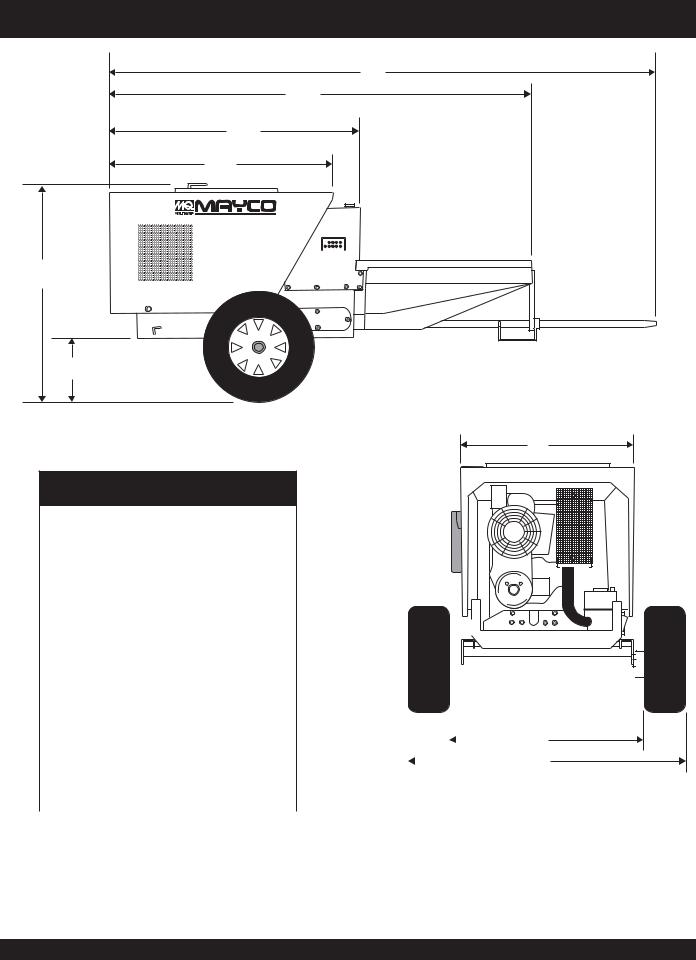
MG-30 PUMP — DIMENSIONS (MG30-M2D MOBILE UNIT)
I
M
L
K
MG30-M2D
|
|
|
|
|
J |
|
|
|
|
|
|
|
|
|
|
|
|
|
|
|
|
|
|
|
|
|
|
|
|
|
|
|
|
|
|
|
|
Table 5. Dimensions Mobil Unit |
|
|
|
|||
|
|
|
|
|
|
|
|
|
|
|
REF. |
DIMENSIONS |
|
|
|
||
|
|
|
|
|
|
|
|
|
|
|
A |
68.0 |
in. (1.72 meters) |
|
|
|
|
|
|
|
|
|
|
|
|
|
|
|
B |
90.0 |
in. (2.28 meters) |
|
|
|
|
|
|
|
|
|
|
|
|
|
|
|
C |
40.0 |
in. (1.01 meters) |
|
|
|
|
|
|
|
|
|
|
|
|
|
|
|
D |
42.0 |
in. (1.06 meters) |
|
|
|
|
|
|
|
|
|
|
|
|
|
|
|
E |
32.0 |
in. (.812 meters) |
|
G |
||
|
|
|
|
|
|
|
|
|
|
|
F |
79.0 |
in. (2.00 meters) |
|
|
|
|
|
|
|
|
|
|
|
|
|
|
|
G |
58.0 |
in. (1.47 meters) |
|
|
|
|
|
|
|
|
|
|
|
|
|
|
|
H |
68.0 |
in. (1.72 meters) |
|
|
|
|
|
|
|
|
|
|
|
|
|
|
|
I |
171 in. (4.34 meters) |
|
|
|
||
|
|
|
|
|
|
|
|
|
|
|
J |
111 in. (2.81 meters) |
|
|
|
||
|
|
|
|
|
|
|
|
|
|
|
K |
54.0 |
in. (1.37 meters) |
|
|
|
|
|
|
|
|
|
|
|
|
|
|
|
L |
60.5 |
in. (1.53 meters) |
|
|
|
|
|
|
|
|
|
|
|
|
|
|
|
M |
38 in. (.965 meters) |
|
|
|
||
|
|
|
|
|
|
|
|
|
|
F |
|
D |
E |
C |
|
H |
A
B
Figure 3. MG-30 (Mobil Unit Dimensions)
PAGE 16 — MAYCO MG-30 PUMP — OPERATION AND PARTS MANUAL — REV. #3 (09/15/11)
MG-30 PUMP — DIMENSIONS (MG30-TD2TAG UNIT)
H
G
F
E
D
MG30-2
I
Table 6. Dimensions Tag Unit
REF. |
DIMENSIONS |
|
|
|
|
|
|
|
|
|
|
|
|
||
|
|
|
|
|
|
|
|
|
|
|
|
||||
|
|
|
|
|
|
|
|
|
|
|
|
|
|
|
|
|
|
|
|
|
|
|
|
|
|
|
|
|
|
|
|
A |
43.0 |
in. (1.09 meters) |
|
|
|
|
|
|
|
|
|
|
|
|
|
|
|
|
|
|
|
|
|
|
|
|
|
||||
|
|
|
|
|
|
|
|
|
|
|
|
|
|
|
|
|
|
|
|
|
|
|
|
|
|
|
|
|
|
|
|
|
|
|
|
|
|
|
|
|
|
|
|
|
|
|
|
B |
60.0 |
in. (1.52 meters) |
|
|
|
|
|
|
|
|
|
|
|
|
|
|
|
|
|
|
|
|
|
|
|
|
|
|
|
|
|
C |
34.5 |
in. (.876 meters) |
|
|
|
|
|
|
|
|
|
|
|
|
|
|
|
|
|
|
|
|
|
|
|
|
|
|
|
|
|
D |
46.5 |
in. (1.18 meters) |
|
|
|
|
|
|
|
|
|
|
|
|
|
|
|
|
|
|
|
|
|
|
|
|
|
||||
E |
54.0 |
in. (1.37 |
meters) |
|
|
|
|
|
|
|
|
|
|
|
|
|
|
|
|
|
|
|
|
|
|
|
|
||||
|
|
|
|
|
|
|
|
|
|
|
|
||||
|
|
|
|
|
|
|
|
|
|
|
|
|
|
|
|
F |
60.5 |
in. (1.53 |
meters) |
|
|
|
|
|
|
|
|
|
|
|
|
G |
96.0 |
in. (2.43 |
meters) |
|
|
|
|
|
|
|
|
|
|
|
|
|
|
|
|
|
|
|
|
|
|
|
|
|
|
|
|
H |
120 in. (3.04 meters) |
|
|
|
|
|
|
|
|
|
|
|
|
||
|
|
|
|
|
|
|
|
|
|
|
|
||||
|
|
|
|
|
|
|
|
|
|
|
|
|
|
|
|
I |
11.5 in. (.292 meters) |
|
|
|
|
|
|
|
|
|
|
|
|
||
|
|
|
|
|
|
|
|
|
|
|
|
|
|
|
|
C
A B
Figure 4. MG-30 (Tag Unit Dimensions)
MAYCO MG-30 PUMP — OPERATION AND PARTS MANUAL — REV. #3 (09/15/11) — PAGE 17

MG-30 PUMP — GENERAL INFORMATION
General
The MAYCO Model MG30-M and MG30T plaster-mortar, fireproofing pumps are designed to pump material at a steady rate of flow.This is accomplished with two pistons. One piston does all the pumping; the other is a slave piston. The slave piston is a compensation piston and operates in a manner which causes the pulsating material from the pumping piston to be pumped at a steady rate of flow.
Your MAYCO pump has been serviced and test-run at the factory. Upon delivery and inspection the machine is ready for operation on the job.
This pump uses a 3-1/2 inch pumping piston and therefore develops a higher pressure than most concrete pumps. It is extremely critical that the pump drive components, pumping lines and components are of the finest quality and maintained in a manner to prevent accidents. Use only high pressure rated hoses and couplings.
The MG-30 has been assembled with a pressure relief valve installed at the discharge port on the manifold. NEVER pump materials unless this (pressure relief valve) mechanism is installed.
Normally, the 750 psi rated brass cap is used in plaster applications, whereas the 1,000 psi rated unit is used for higher pressure applications and fireproofing. The brass cap and ball should be removed and cleaned daily, or more often if necessary, to prevent material setting up around the ball.
If material hardens around the ball, it will not be effective as a relief valve when high pressure develops. Install ball discharge in downward position. Use the manual relief part of this valve to relieve line pressure before disconnecting material lines or hoses
Power for the operation of this pump is supplied by a Hatz Model 2M41LZ, 35 H.P.diesel air-cooled engine. This engine transfers power through a V-belt to a totally enclosed speed reducer and also operates a twin-cylinder piston type air compressor.
The MG-30 is equipped with an electrically controlled solenoid valve and gravity-feed piston oiler system. The electrically controlled solenoid allows the operator to start and stop the pump remotely from the nozzle.
When the solenoid valve is energized (i.e. electric current is applied to the solenoid) the engine speed will increase to the pre-set governed speed, engaging the centrifugal clutch and pump. When the solenoid is de-energized, the engine speed will decrease, returning to idle, disengaging the centrifugal clutch and pump.
Located at the rear of the pump is the mixing unit. The drum batch capacity of this mixing unit is between 3.5 and 4.0 bags.
The mixer section of the pump can be powered by a either a XX HP Honda gasoline engine, 8.0 HP Hatz diesel or 2.0 HP electric motor.
Due to the abrasive nature of the materials being pumped, some parts of the machine are likely to be worn from use more rapidly than others. It is therefore suggested that spare parts be kept in ready reserve at the job site to prevent downtime.
CAUTION :
If hoses or lines are blocked for any reason, or if lines are kinked when starting up or during pumping cycle, the pump pressure could straighten out the kink or force out the blockage. The rapid surge of material could cause the lines
to whip or move in a manner that could cause injury to personnel. When moving hoses from one job site application to another it is important to walk the entire system and visually inspect for any kinks. or sharp bends in the hose, before starting or resumong the pumping operation.
The following definitions will help assist you in understanding common pump terminology.
Centrifugal Clutch
The centrifugal clutch is designed to slip when the engine speed drops due to overloading of the pump. This is a safety device to protect other parts of the machine from damage and to prevent a buildup of pressure in the material hose. Continued operation of the machine when the clutch is slipping will cause damage to the clutch. The clutch needs no adjustment or lubrication.
Pump Head Unit
The pump head unit consists of two pistons--one being the pumping piston and the other a compensating piston, driven by the cam and rocker arm principle.
The pump housing is equipped with inlet and outlet valve seats and two special hard rubber or steel balls. When the piston is retracted, the inlet valve seat opens for intake of material into the piston chamber; when the piston is extended, the inlet valve closes and the outlet valve opens, allowing material to be pumped. There are three sections to the pump head unit.
ALWAYS ASSEMBLE THESE SECTIONS PRIOR TO MOUNTING PUMP HEAD UNIT ON FRAME, MAKING SURE THE SEAL RINGS FIT UP AIRTIGHT.
PAGE 18 — MAYCO MG-30 PUMP — OPERATION AND PARTS MANUAL — REV. #3 (09/15/11)

MG-30 PUMP — GENERAL INFORMATION
Main Bearings
The two main crankshaft bearings are sealed bearings.These bearings should be greased about every two days of pump operation.Any good lithium base grease is acceptable.Too much grease cause the bearings to overheat.
Rocker Arm Shaft
The two rocker arms have bronze bearings. These bearings should be greased every day of operation.
Rod Ends
Each piston rod and connecting rod from the crankshaft has a roller bearing. Lubricate these four roller bearing daily with lithium base grease.
Daily lubrication of the roller bearings
(except main bearing) will prevent any NOTE dirt and foreign matter from entering the
bearings.
Cylinders
The cylinder walls do not wear to any degree. Care should be taken not to damage the surface on the ends of the cylinders as this will cause an air leak between the end of the cylinders and the pump housing.
NOTE
Pump Housing
NEVER! use muriatic acid to clean the pump. The cylinder bore is chrome plated. Muriatic acid will dissolve the chrome.
There are 3 sections to the pump housing, hopper elbow, main housing (center), and crossover housing.These 3 housings are held together with "T" slot bolts and are aligned to each other with guide rings on the flange surface.
Always assemble these 3 sections into a complete unit before placing it on the pump. It is important that when the pump housing unit is placed on the pump that all of the gaskets and o-rings are aligned properly with an air tight fit.
Rubber Check Ball
Rubber check balls (not steel) are used in plaster and stucco applications, because they form a water tight seal at the valve seat. This prevents the check valve from packing due to separation at the valve.
The rubber check balls are components of the pump that will wear quite rapidly and must be replace frequently. Excessive high pressure is the main cause of wear to the rubber check balls.The rubber check balls can last anywhere from a week to 2 or 3 days depending on the pumping pressure. Jamming the pump or running the pump at a very high pressure may split the rubber check balls.
NOTE
Steel Check Ball
When replacing either rubber check ball, always inspect the other ball for signs of wear. Make sure the o-rings and associated parts are clean and free of dirt when the rubber check valve is reassembled.
Steel check balls are used in fireproofing applications, because they form a water tight seal at the valve seat.This prevents the check valve from packing due to separation at the valve.
Leather Piston Cup
The piston, which is held to the push rod by a nut, consists of several parts made of various materials with close tolerances, having as the center a pre-lubricated leather piston cup. This cup is in constant contact with the cylinder and the material and it wipes clean the cylinder on each stroke, thereby preventing damage to the cylinder. When the machine is shut down, the piston cups should be periodically inspected and replaced if frayed or damaged.
The leather piston cups will outwear the rubber balls.The leather piston cups as well as the rubber balls can be damaged prematurely if exposed to excessive pump pressure or jamming of the pump.
Leather Piston Lubrication
Due to the close tolerance of the piston to the cylinder, the piston is equipped with a felt ring to keep the cylinder constantly lubricated for increased life. The felt ring is lubricated through the oiler fitting and tubing installed at rear of piston.
The oiler tank is mounted adjacent to the fuel tank. The oil level should be checked regularly during operation and tank filled, if necessary, with a good grade of S.A.E. 20W or 30W motor oil. Oiler tank capacity is 1.5 quarts (.709 liters).
With the engine running, open needle valve (located below oil tank) very slightly. Oil should flow for approximately 5 minutes before pumping material. This will allow oil to reach and penetrate the felt ring. Opening the valve too far will cause oil to flow excessively. Close the valve when the machine is not in use to prevent all the oil draining from the tank.
MAYCO MG-30 PUMP — OPERATION AND PARTS MANUAL — REV. #3 (09/15/11) — PAGE 19

MG-30 PUMP — GENERAL INFORMATION
O-Rings
O-Rings have been installed at sealing points throughout the pump head unit. These O-rings act as seals and are very important for the efficiency of the machine. Great care should be taken when assembling or disassembling those parts where “O” rings have been installed. Always clean O-ring groove thoroughly grease O-ring before installing.
Inspection of O-rings should be made regularly. It should be done each time a part containing an O-ring has been disassembled. Carefully remove and check O-ring to see it is not chipped, broken, peeled or has any other signs of deformity. If any of these conditions exists, the O-ring should be replaced.
USE ONLY "O-RINGS" OBTAINED
NOTE FROM THE FACTORY, as they are manufactured of a special hardened
rubber to meet this specific application.
Valve Seats
The valve seats are a loose fit in the pump housing.There are no set screws holding them in place. When the valve seat has been worn to a point where a new rubber check ball strikes the bar in the valve seat (keeping the ball from seating properly), the valve seat should be replaced.
Sand Packs
Washed sand left in the material hose can cause a sand pack (clog) in the hose. When the material hose is washed out, make sure all of the loose sand is washed out of the hose. If loose sand is allowed to remain in the hose, the new material coming through the hose will push the sand ahead until it forms a clog in the hose.
Separation
Separation in the pump or the material hose is caused by water being forced out of the material through a loose connection. Make sure that none of the gaskets or o-rings in the pumping system leak. Loose hose connections are one of the most common causes of separation.
Whenever water leaks out through a hose connection, the material will build up slowly.In an hour or so, depending on how bad the leak, a restriction will form at the connection causing the pump to work much harder to force the material through the restriction. This also slows down the output production of the pump. If this condition is not corrected, the pump will jam and stop.
Pump Overloading
If at any time the pump is jammed from separation or a sand pack in the hose, the clutch on the engine will slip. This will protect the moving mechanical parts of the pump from being overloaded and damaged. The capability allows the pump to shut itself down in the event an operator is not near pump if a sand pack or jam-up occurs.
When the drive belt is moved from the largest pulley on the clutch to the smallest, the output power of the pump is increased by a factor of three. So, when operating the pump at the lower speed, the RPM of the engine should also be reduced.This will allow the clutch to slip in the event of a separation or sand pack, and therefore will safeguard the hoses and the mechanical working parts of the pump from damage.
Operating the pump at lower speeds NOTE (placing the drive belt in either of the two pulley groves next to the engine) will develop high pressure in the material
hoses when the pumping of stiff materials is required. Make sure that all hoses are in good condition and that all connections are air tight. When using the lower pumping speeds, run the engine at a lower speed.
Leaks
Water can become separated from the material being pumped. This is usually caused by loose connections or damaged seals. When separation occurs, a restriction caused by a buildup of material around the leak forces the pump to work harder. As a result, pump output is lowered and eventually the pump will stop.
Hose and Fittings
Due to the high pressure which the machine is capable of producing we recommend the use of specially constructed MAYCO hose. This hose has been designed to withstand the pressures required to pump the material.
MAYCO hoses are available in 25 ft.and 50 ft.lengths. Each size is equipped with a male insert on each end.
It is suggested to use all 2-inch (5.08 cm.) hose with the exception of the last 25 or 50 ft. This should be 1.5 inch (3.81 cm.) hose, to be used as a whipline.
Wheels
The machine is equipped with pneumatic (air) type wheels, rotating on tapered roller bearings. These bearings have been packed at the factory and need not be repacked for approximately 6 months, at which time they should be removed, cleaned and repacked with a good grade of wheel bearing grease.
PAGE 20 — MAYCO MG-30 PUMP — OPERATION AND PARTS MANUAL — REV. #3 (09/15/11)
MG-30 PUMP — GENERAL INFORMATION
Reducers and unions are available for connecting the various sizes of hose.
Connecting material hoses by means of any type of quick coupling device is not NOTE recommended because they generally do not have an adequate pressure rating
and are hazardous.
Air Compressor
Your plaster and mortar pump is equipped with a piston type Quincy Air Compressor, driven by V-belts from the engine. This air compressor supplies air to the nozzle for spraying of material.
Factors Affecting Hose Pressure
Stiffness of the mix is the most important factor affecting hose pressure. There are others, however, that can be equally important.
1. Hose Length – Pressure varies directly with the length of the hose. The pump must develop twice as much pressure with a 100-ft. length of hose as it does with a 50-ft. length.
2. Hose Size – The pressure required to pump material through a hose varies with the area of the hose. Thus, if the pressure required for a length of 2-inch diameter (5.08 cm.) hose is 300 pounds (136 Kg.), the pressure required for the same length of 1.5-inch diameter (3.81 cm.) hose would be over 500 pounds (227 Kg.) using the same pumping
|
rate. |
3. |
Gypsum – In using gypsum plaster a rich mix (such as |
|
2:1) will take more pressure to pump than a leaner mix. In |
|
a 2:1 mix you will probably have to make your mix |
|
somewhat softer than a 3:1 mix. |
4. |
Binders – Some binders for plaster take more pressure |
|
than others. A plaster using gypsum will require the most |
|
pressure. Portland Cement pumps quite easily with a |
|
minimum of pressure, as does clay or lime. |
5. |
Aggregates – The most familiar types of aggregate are |
|
sand, vermiculite, perlite and zonolite. Each one of these |
|
has its own characteristics. As most sand absorbs very |
|
little water, it is the easiest with which to control the |
consistency of materials. vermiculite or zonolite, on the other hand, absorb considerably more water when pumped under pressure, as do most perlites. Therefore, in the latter cases, whether the binder is gypsum or Portland Cement, your mix must be somewhat softer.
|
All materials being pumped become |
|
NOTE |
stiffer, when applied under pressure. |
|
Therefore, the mix at the machine must |
||
|
||
|
be softer than if it were taken from the |
|
|
mixer for hand application. |
Effect of Hose Pressure On Height
When elevating a plaster containing gypsum and light weight aggregate add about one-half pound per square inch to the required horizontal pump pressure for every foot you elevate the nozzle above the Mayco Model MG-30 plastering unit. This additional pressure is generally not serious because you will probably be running between 1 and 2 lbs. per square inch per foot. to overcome friction in the hose.
As an example, if you were using a 40 ft. (12 meters) hose with a pressure of 1-1/2 psi per foot or a total of 60 psi when plastering a wall, and you sprayed a 20 ft. (6 meters) ceiling, you would only increasethepressure10lbs.(4.53Kg.)orhaveatotalof70 lbs. (32 Kg.) pump pressure. If you wanted to spray a 40 ft. (12 meters) ceiling and needed another 40 ft. (12 meters) of hose, your pump pressure would be:
First 40 feet @ 1-1/2 psi/ft. ............. |
60 psi |
Second 40 feet@ 1-1/2 psi/ft. ......... |
60 psi |
Elevation pressure 40 psi/2 ........... |
20 psi |
Total pump pressure....... |
140 psi |
Material hose, steel delivery line and couplings are available in various pressure ratings when new. Age wear andtear will reduce the above calculated pressure rating.
Nozzle
The MAYCO spray nozzle is constructed of a lightweight material. It has been designed with a removable cap for changing to various size orifices and is also equipped with an atomizer for variance in spray patterns.
The output from the spray nozzle can be controlled to supply a volume from zero to 4.5 cu. ft. per minute. Because of this considerable range in volume, the orifice in the nozzle must be changed to fit the desired volume in order to obtain a good pattern.
In most cases a 5/8-inch (1.58 cm.) orifice will give a good pattern in most browning or scratching applied to paperback wire. On metal lath you should use as large an orifice as possible and lower the air pressure. In most cases the air jet should be set back from the orifice 1/2 to 5/8 inch (1.27 to 1.58 cm.). You will find an air valve at the nozzle to control the air pressure.
MAYCO MG-30 PUMP — OPERATION AND PARTS MANUAL — REV. #3 (09/15/11) — PAGE 21

MG-30 PUMP — GENERAL INFORMATION
To change from a fine texture to a heavy browning pattern, follow these steps:
1.Lower the air pressure.
2.Change to a larger size orifice.
3.Set the air jet farther back from the orifice.
4.Increase the volume of material.
To increase nozzle frequency and obtain small plaster globules, reverse the above procedure.
How the Nozzle Operates
With the machine running at a rate to brown 80 square yards 1/2" thick, you should use a 1/2-inch (1.27cm.) orifice and the distance from the air stem to the orifice would be 3/8-inch (.952 cm.). To scratchmetallathatthesamepumpingspeed,youwouldsettheair stemfrom1/2to5/8-inch(1.27to1.58cm.)fromtheorifice,andyou would probably use a 5/8-inch (1.58 cm) orifice.
When adjusting the air pressure, it is desirable to get a good even pattern in the spray.If the air pressure is too high, the plaster will rebound from the wall.If the air pressure is too low, the spray pattern will be very narrow and plaster cannot be sprayed on ‘evenly.Adjust air pressure at nozzle to obtain the desired pattern.
Since the operator feels little or no pulsation when running the Mayco Model MG30 plastering unit, it would appear that plaster comes from the nozzle in a steady stream.Actually, in operation, a globule of plaster comes from the nozzle and is then followed by a globule of compressed air.
The Mayco nozzle can be operated with as few as 50 plaster globules per second, or a frequency of 50 cycles per second, and as high as 1,000 cycles per second with the pump operating at a constant volume.
When the nozzle is emitting 50 plaster globules per second, each globule is 20 times the size of the plaster globules emitted when the nozzle is set for 1000 plaster globules per second. Here lies the basis for the various applications of the Mayco Model MG30.
For example, when a fine texture is desired, the nozzle should operate at a high frequency to break the plaster up into small particles. In scratching metal lath, it is desirable to produce large plaster globules that will adhere to the metal lath. Difference in frequency can be detected by the sound of the nozzle in operation. When the sound at the nozzle is high, almost at a scream like pitch, the frequency is high and the globule size is small.
ESSICK MIXER
The Essick Model EM120SM plaster and mortar mixer is shipped completely assembled and has been factory tested.
The drum batch capacity of these mixers is between 3.5 and 4.0 bags. With proper care, they will give continuous service year-after-year.
This mixer is powered by a HATZ Model 1B30, 8.0 HP diesel engine. The power from the engine is transmitted via a clutch/ reduction assembly that is coupled directly to the paddle shaft. Therefore providing high mixer torque and eliminating V-belts .
BEFORE STARTING
Before starting the engine, read the engine owners manual and thoroughly understand the safety information.
OIL LEVELS
Be sure to check the oil levels in the engine and transmission before starting the mixer.
DIESEL ENGINE CARE
For care and operation of either HATZ diesel engine, refer to the engine manufacturer’s operating instructions furnished with the engine. We recommend draining and refilling the engine crankcase at least every thirty hours of operation. Check the engine oil level daily.
PAGE 22 — MAYCO MG-30 PUMP — OPERATION AND PARTS MANUAL — REV. #3 (09/15/11)
MG-30 PUMP — APPLICATION
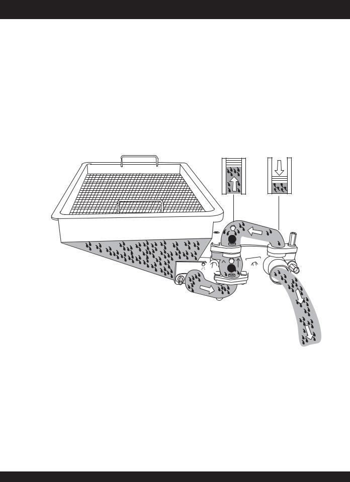
How It Works
The Mayco Plaster Pump, Model MG-30 designed to pump materials at a steady rate of flow. This is done by using two cylinders.The crank powered pumping cylinder does all of the pumping. The cam powered slave cylinder is a compensating cylinder and operates in a manner which causes the pulsating material from the pumping cylinder to be pumped at a steady rate of flow.The slave cylinder will not move until enough pressure is developed to produce this steady rate of flow.
As shown in Figure 5, the pumping cylinder retracts drawing the material past the ball A and filling the cylinder.The slave cylinder is pumping the material out to the nozzle and causing ball B to seat preventing the material from returning to the pumping cylinder intake.
PUMPING SLAVE CYLINDER CYLINDER INTAKE INTAKE
HOPPER


 B
B 


 A
A 

DISCHARGE
Figure 5. Pumping Cylinder (Discharge)
MAYCO MG-30 PUMP — OPERATION AND PARTS MANUAL — REV. #3 (09/15/11) — PAGE 23
MG-30 PUMP — APPLICATION
The pumping cylinder (Figure 6) is forcing the material past ball B and out to the nozzle, also seating ball A so that the material will not flow back to the hopper. This action also fills the slave cylinder for the next stroke.
The slave piston will not move until enough pressure is developed to produce a steady rate of flow.
PUMPING SLAVE
CYLINDER CYLINDER
PUMPING INTAKE
HOPPER |
B |
|


 A
A 
N0
DISCHARGE
Figure 6. Pumping Cylinder (No Discharge)
PAGE 24 — MAYCO MG-30 PUMP — OPERATION AND PARTS MANUAL — REV. #3 (09/15/11)
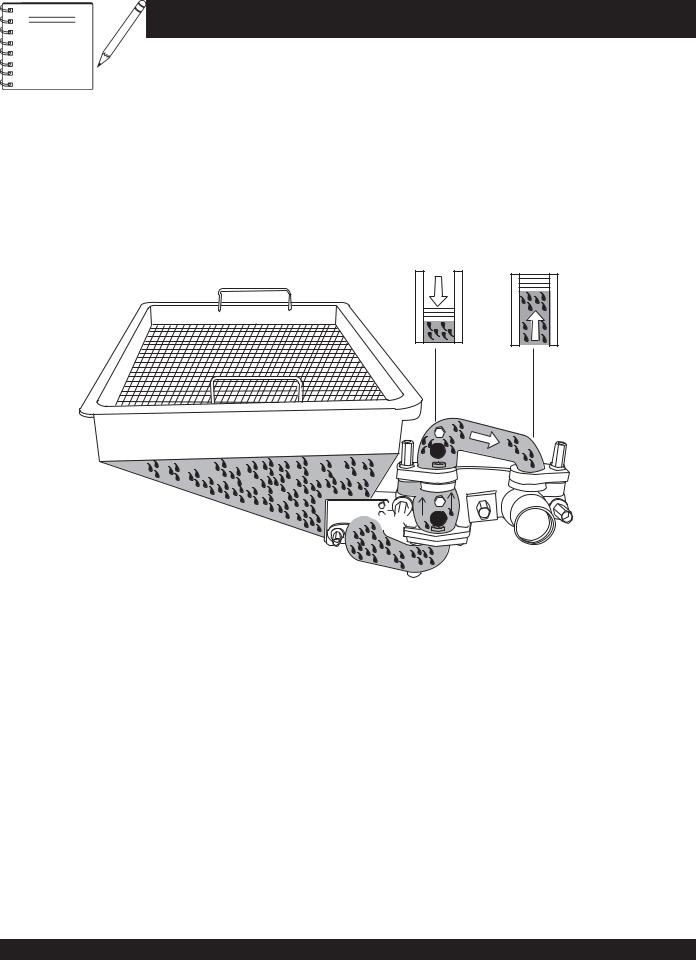
Pressure ReliefValve (Automatic)
Purpose
To provide the capability that will automatically release the pressure in a material hose or line whenever the flow of material is restricted for any reason, causing unsafe pressure to build up in the hose or line.
SafetyValve Placement (Automatic)
Place the automatic safety valve at the outlet side of the plaster pump, ahead of the hose connection.This automatic safety valve is to be used in conjunction with the manual release mechanism (safety relief pressure plug).
Theory of Operation
Located on the bottom of the safety relief pressure valve
(Figure 7), is a pipe nipple with an opening which is sealed off with a rubber ball that is held against the opening with a brass cap.
It is the responsibility of the pump operator to ensure that the delivery hose and line system with all clamps and accessories have a higher pressure rating than the safety cap being used.
Figure 7. Safety Relief PressureValve
(Automatic Mode)
MG-30 PUMP — APPLICATION
NEVER place the MG-30 into operation without a safety relief pressure valve with a manual release control installed on the pump discharge.
ALWAYS point the brass cap on the safety valve downward. This will prevent the ball from striking someone and possibly causing injury.
Suggestion:
DO NOT use a 1000 psi cap if your pumping requirement is less than 750 psi. Always use a cap that is rated less than the total system pressure.
The rubber ball will stay in place until an excessive amount of pressure occurs that will cause the ball to blow out through the opening (Figure 8) in the brass cap and release the pressure in the hose or line.
Figure 8. Safety Relief PressureValve
(Rubber Check Ball Release)
MAYCO MG-30 PUMP — OPERATION AND PARTS MANUAL — REV. #3 (09/15/11) — PAGE 25
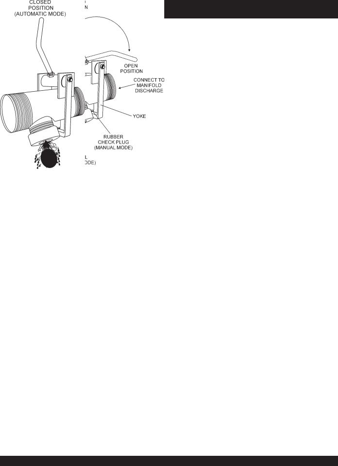
Pressure Relief Plug (Manual Operation)
Purpose
To provide the capability that will manually release the pressure in a material hose or line whenever the flow of material is restricted for any reason, causing unsafe pressure to build up in the hose or line.
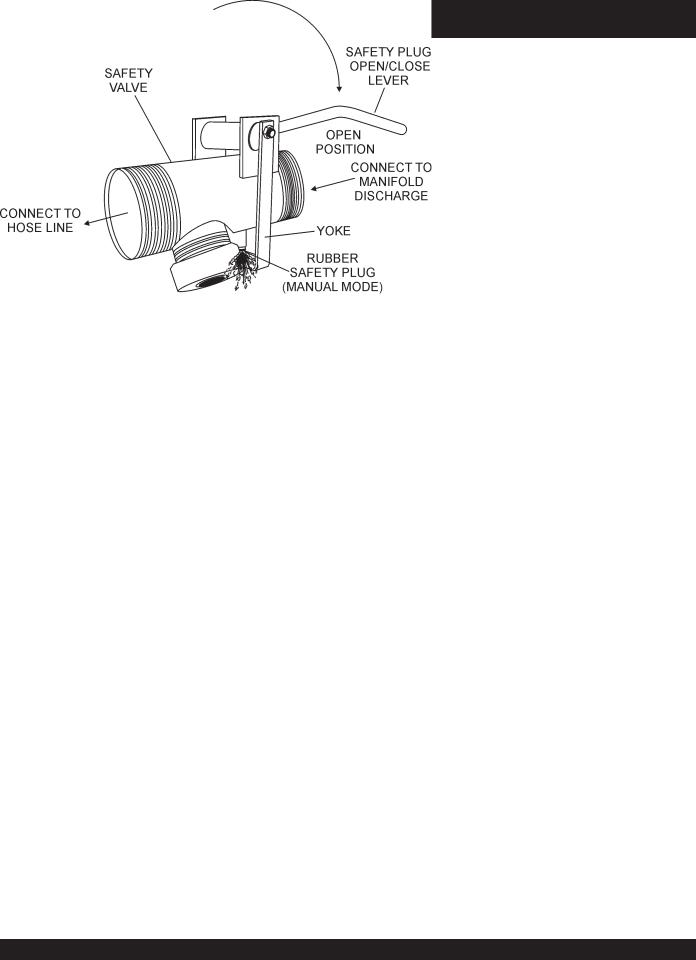
SafetyValve Placement (Manual)
Place the safety relief pressure valve (Figure 9) at the discharge side of the plaster pump, ahead of the hose connection. Located on the pressure relief valve is a rubber pressure release plug (manual activation), the plug is held in position by a steel clamp (yoke) and is activated by pulling the lever downward to release the pressure in the system.
This manual pressure release plug is to be used in conjunction with the automatic release mechanism (rubber check ball).
ALWAYS open the manual pressure NOTE release plug before disconnecting any part of the delivery hose, line or
clamp system.
Anytime it is necessary to uncouple or remove any part of the delivery system, the manual pressure release plug must be opened to relieve pressure in the system.
MG-30 PUMP — APPLICATION
Before activating the manual pressure release plug the operator must do the following:
1.Stop the engine.
2.Warn all workers and bystanders to stand at least 20 feet away from the pump and turn their heads away from the pressure relief safety valve.
3.The operator shall position himself/herself beside the pressure relief safety valve with his/hers back to the pump.
4.Wearing safety glasses, reach down with one hand, grasp the release lever on top of the safety valve.
5.Turnheadawayfromthepressurereleaseplugandliftlever upwards (open).
6.Remain facing away from the pressure relief valve until counting up to 20, slowly.By that time, the material ejecting underpressurewillbeslowlydischarging.Workcanresume only after the material has been discharged for a minimum of 20 seconds.
7.Aftercorrectingtheproblemthatcausedtheexcesspressure in the system line, close the safety plug by pushing the plug open/close lever downward (closed), and resume pumping.
Figure 9. Rubber Safety Relief Pressure Plug
PAGE 26 — MAYCO MG-30 PUMP — OPERATION AND PARTS MANUAL — REV. #3 (09/15/11)
MG-30 PUMP — MIXER MAJOR COMPONENTS
3
2
13 9
4 |
5 |
12 |
|
10


 11 1
11 1 


7
8
5
7
6
Figure 10. Mixer Major Components
Figure 10 illustrates the major components and controls of the mixer.
1.Mixing Drum — Made of steel. Mixing materials such as concrete, mortar, plaster are to be placed into this drum for mixing. Always clean the drum after each use. Drum capacity is 12 cu. ft.
2.Mixing Paddles — Used in the mixing of material. This unit uses four different types of paddles to provide a fast uniform mix.
3.Bag Cutter— This feature allows compound mixing bags to be opened easily, therefore allowing the contents of the bag to fall directly into the mixing drum. Bag capacity is 3.5 to 4 bags.
4.Transmission — Totally inclosed oil bath transmission.
5.Engine Cover — Lift this cover to gain access to the engine and transmission compartments.
6.Engine — The mixer unit is powered by a Hatz Model IB30, 8.5 HP diesel engine. See page 30 for engine component definitions.
7.Engine Cover Grip — Place hand inside grip then lift upwards to raise cover.When lifting of the cover is required make sure both rubber bunjee latches have been released.
8.Rubber Latch — Use this latch to secure the engine compartment cover.
8.Clutch Lever — Push the clutch lever forward, toward the tow (tongue) end of the mixer to engage clutch. Once clutch is engaged paddle shaft will rotate. To disengage clutch pull the clutch backwards towards the engine.
9.Dump Handle — Pull this handle downward to dump the contents of the drum. Push the handle upward to return the drum to its vertical position.
10.Pivot Point/Zerk Fitting — There is, on each end of the mixing drum a zerk grease fitting.These fittings lubricate the dumping mechanism. Lubricate both fittings at least twice a week.
12.Safety Grill Lock Handle — To prevent injury to hands and arms, the safety grill should ALWAYS be locked when the mixing of plaster or mortar is required. Also when transporting the mixer the safety grill should be locked.The safety grill should only be un-locked when cleaning of the blades and drum is required.
13.Safety Grill — Provided for operator safety.This safety grill is designed to keep hands and solid objects out of the mixing drum when in use.This grill should be closed at all times when pump is in use. DO NOT remove the grill or grill opening bar. Keep the grill clean by washing it down daily.
MAYCO MG-30 PUMP — OPERATION AND PARTS MANUAL — REV. #3 (09/15/11) — PAGE 27

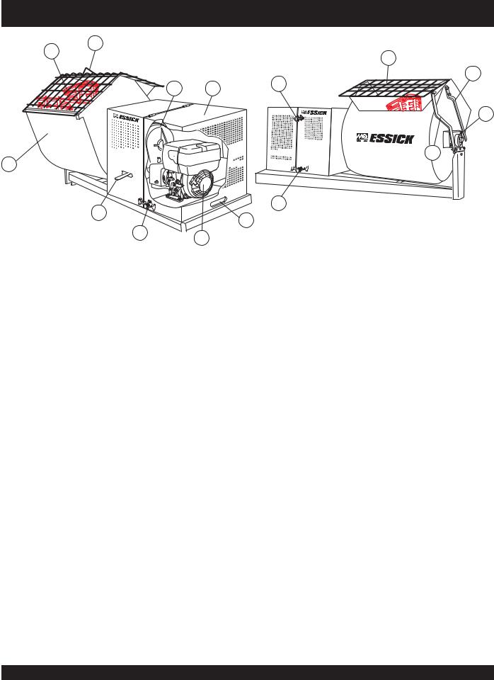
MG-30 PUMP — MG30 M2D MAJOR COMPONENTS
Figure 11 illustrates the major components and controls of
the MG-30 (Mobil Unit).
3
7 |
8 |
|
4 5 6
9


 10 12
10 12 


2
13


 MG30 -
  M2D
M2D
11
1
Figure 11. MG-30 Major Components
14
|
15 |
|
|
16 |
|
22 |
|
|
|
19 |
|
23 |
20 |
|
17 |
||
|
24
21
18
26
25
PAGE 28 — MAYCO MG-30 PUMP — OPERATION AND PARTS MANUAL — REV. #3 (09/15/11)

MG-30 PUMP — MG30-M2D MAJOR COMPOUNDS
1.Manifold — Cast steel manifold, 2 in.(5.08 cm.) for plaster, 3 inch (7.62 cm.) for fireproofing.This manifold is designed with a manual pressure relief valve and an automatic safety pressure relief valve rated between 700-1000 PSI.
14.Piston Oiler Tank— Fill this tank to the "FULL" level for normal operating conditions. Check regularly.Fill with SAE 30 wt. type motor oil. Oilertankcapacityis1-1/2quarts(1.14 liters).
2. Tires — This trailer uses two ST205-750 x14C type tires. |
15. |
Tire inflation pressure is the most important factor in tire |
|
life. Pressure should be checked to 50 psi cold before |
|
operation. DO NOT bleed air from tires when they are hot. |
16. |
Check inflation pressure weekly during use to insure the |
|
maximum tire life and tread wear.
Lubrication Port Panel — Central grease panel. All lubrication points can be accessed via this panel. Allows lubrication of all bearings without lifting the hood.
Hopper — This unit uses a galvanized hopper which can hold up to 12.0 cu. ft. (340 liters) of mix. NEVER put hands or any other parts of you body into the hopper.
3.Mixer—This unit uses a "Essick " mechanical 12 ft3 mortar 17. Mixer End Jack Stand – Use this jack stand to level
|
and plaster mixer. See page 27 for mixer component |
|
and support the pump. |
|
|
definitions. |
18. Lubrication Box Access Cover – There are four access |
||
4. |
Oiler — Cam bearing oiler.Fill with SAE 20 or 30 wt. motor |
|||
|
covers on the pump. Remove these doors to gain access to |
|||
|
oil. Lubricates cam surface. |
|
drive and piston assemblies when maintenance is required. |
|
5. |
Fuel Gauge/Fuel Cap — Read the top of this cap to |
19. |
Gear Reduction Adjustment Bolt – Loosen this bolt to |
|
|
determine if the fuel level is low. If fuel level is low, remove |
|
pivot the gearbox assembly upwards or downwards.This |
|
|
cap to add #2 diesel fuel. |
|
will allow for the placement of the V-belt on one of the four |
|
6. |
Gear Reduction Pulley — This is an adjustable 4-groove |
|
pulley grooves. |
|
20. |
Battery –This unit uses a +12 VDC type battery.ALWAYS |
|||
|
pulley. Select the pulley speed that fits your pumping |
|||
|
requirement. |
|
use gloves and eye protection when handling the battery. |
|
7. |
Compartment Hood Lift Handles — There are two |
21. |
Air Compressor – This unit uses a piston type Quincy |
|
|
compartment hood lift handles located on each side of the |
|
Air Compressor, driven by V-belts from the engine. This |
|
|
hood. Grip handle and pull upwards to lift hood. |
|
air compressor supplies air to the nozzle for spraying of |
|
8. |
Compartment Hood — This hood encloses the engine, |
|
material. The compressor has an output of 10 CFM @ 100 |
|
|
psi. A weekly check should be made of the crankcase oil |
|||
|
compressor, gear reduction pulley, reduction gearbox, |
|
||
|
|
level to make sure it is at the full mark, or at least between |
||
|
battery, control box and other associated components |
|
||
|
|
the two marks on the dipstick. |
||
|
required to operate the pump. NEVER! operate the pump |
|
||
|
22. |
Throttle Control Knob – This is a variable speed type |
||
|
with the hood in the up position. |
|||
9. |
View AccessWindow — This opening allows the user to |
|
control. Turning the throttle lock (CCW) left unlocks the |
|
|
throttle allowing the throttle control cable to be pulled out to |
|||
|
start the unit and have access to the control box without |
|
||
|
|
the desired position. Once the desired throttle position |
||
|
lifting the compartment hood. |
|
||
|
|
(speed) has been achieved, turning the throttle lock to the |
||
10. |
Access Cover/Handle — Turn this handle clockwise to |
|
||
|
(CW) right locks it in place. Use the fine tune adjustment |
|||
|
release latch, then lift upwards. When this cover is in the |
|
knob to fine tune the engine rpm's. |
|
|
open position it will provide a more free flow of air to help |
|
To place the engine in idle, press the top button inward all |
|
|
keep the engine and associated components cool. |
|
||
|
|
the way. |
||
|
Documentation Box — Contains information regarding |
|
||
11. |
23. |
Engine –This unit uses a HATZ Model 2M4LZ, 35 HP air |
||
|
the pump and mixer. |
|
cooled diesel engine. See page 31 for engine component |
|
12. |
Speed Reduction Gearbox — A constant-mesh type and |
|
definitions. |
|
|
total enclosed gearbox with all gears immersed in oil. Fill |
24. |
Tow End Jack Stand – Use this jack stand to level and |
|
|
with SAE 90 wt. motor oil. ALWAYS keep gearbox oil at |
|
support the pump. |
|
|
proper operating level. |
25. |
Tow Hitch Coupler – Requires a 2-inch ball hitch or a |
|
13. |
Engine Control Box — Contains the engine ignition |
|
pin. Capable of towing 5,000 lbs. |
|
|
switch, operation switch, engine status LED's (5), hour meter, |
26. |
Chock Blocks – Place these blocks (not included as |
|
|
remote control connector and 25 amp fuse. |
|
part of your concrete pump package) under each wheel |
|
|
|
|
to prevent rolling or when parked on a slope. |
|
MAYCO MG-30 PUMP — OPERATION AND PARTS MANUAL — REV. #3 (09/15/11) — PAGE 29
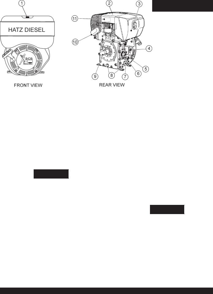
MG-30 PUMP — HATZ 8.5 HP ENGINE COMPONENTS
Figure 12. Hatz Model 1B30 8.5 HP Diesel Engine
INITIAL SERVICING
The mixer's engine (Figure 12) must be checked for proper lubrication and filled with fuel prior to operation. Refer to the manufacturersEnginemanualfor instructions&detailsofoperation andservicing.
1. Fuel Filler Cap/Fuel Tank – Pull this latch to add diesel fuel to the tank. After refueling, always make sure the fuel cap is latched properly. DO NOT over fill. For additional information refer to engine owner's manual.
WARNING
Addingfueltothetankshouldbeaccomplishedonly when the engine is stopped and has had an opportunity to cool down. In the event of a fuel spill,
DO NOT attempt to start the engine until the fuel residue has been completely wiped up, and the area surrounding the engine is dry.
2. Engine Lifting Straps/Cover – Remove the air cleaner cover, then lift this cover (the one with decals on it) to gain access to the engine lifting straps.
3. Air Cleaner/Cover – Prevents dirt and other debris from entering the fuel system. Remove wing-nut on side of air filter cover to gain access to filter element.
4. Speed Control Lever – This lever is connected to the throttle control which is located on the side of the engine compartment cover. Use this lever to control engine speed.
5.Dip Stick – Remove dipstick to determine if the engine oil level is low. If low add oil as specified in Table 4, page 14.
6.Engine Motor Mounts – Attach these engine mounts to the mixer frame.Tighten securely.
7.Oil Filter – Remove this bolt to gain access (internal) to the engine oil filter.Service the oil filter as recommended in the maintenance section of this manual.
8.Oil Drain Plugs – There are two oil drain plugs, one is underneath the flywheel, the other on the side of the engine. Remove these plugs to drain engine oil from the engine crankcase.
9.Crankshaft – Connect this shaft to the input of the transmission.
10. Muffler – Used to reduce noise and emissions.
11. Nameplate – Contains information about the engine.
WARNING
Enginecomponentscangenerateextremeheat. To prevent burns, DO NOT touch these areas while theengine isrunning or immediately after operating. NEVER
operate the engine with the muffler removed.
Operating the engine without an air filter, with a damaged air filter, or a filter in need of replacement will allow dirt to enter the engine, causing rapid engine wear.
PAGE 30 — MAYCO MG-30 PUMP — OPERATION AND PARTS MANUAL — REV. #3 (09/15/11)
 Loading...