


MQP240

THIS MANUAL MUST ACCOMPANY THE EQUIPMENT AT ALL TIMES.
To find the latest revision of this
publication, visit our website at:
www.multiquip.com
MODEL MQP240
60HZ GENERATOR
(CUMMINS QSL9-G3 DIESEL ENGINE)
Revision #0 (10/23/12)
OPERATION AND PARTS MANUAL

PAGE 2 —MQP240 GENERATOR • OPERATION AND PARTS MANUAL — REV. #0 (10/23/12)
PROPOSITION 65 WARNING
Diesel engine exhaust and some of

MQP240 GENERATOR • OPERATION AND PARTS MANUAL — REV. #0 (10/23/12) — PAGE 3
If you believe that your vehicle has a defect that could cause a crash or could cause
injury or death, you should immediately inform the National Highway Traffic Safety
Administration (NHTSA) in addition to notifying Multiquip at 1-800-421-1244.
If NHTSA receives similar complaints, it may open an investigation, and if it finds
that a safety defect exists in a group of vehicles, it may order a recall and remedy
campaign. However, NHTSA cannot become involved in individual problems
between you, your dealer, or Multiquip.
To contact NHTSA, you may either call the Vehicle Safety Hotline toll-free at 1-888-
327-4236 (TTY: 1-800-424-9153), go to http://www.nhtsa.dot.gov; or write to:
Administrator
NHTSA
1200 New Jersey Avenue S.E.
Washington, DC 20590
You can also obtain information about motor vehicle safety from
http://www.safecar.gov.
REPORTING SAFETY DEFECTS

PAGE 4 —MQP240 GENERATOR • OPERATION AND PARTS MANUAL — REV. #0 (10/23/12)
TABLE OF CONTENTS
MQP240 60 Hz Generator
Proposition 65 Warning ........................................... 2
Reporting Safety Defects ......................................... 3
Table Of Contents .................................................... 4
Parts Ordering Procedures ...................................... 5
Safety Information ..............................................6-11
Specifications ........................................................ 12
Dimensions ............................................................ 13
Installation ........................................................14-15
General Information ............................................... 16
Major Components ................................................ 17
Generator Control Panel ................................... 18-19
Engine Operating Panel......................................... 20
Output Terminal Panel Familiarization .............. 22-24
Load Application .................................................... 25
Generator Outputs ............................................ 26-27
Output Terminal Panel Connections ................. 28-29
Inspection/Setup ............................................... 30-33
Generator Start-Up Procedure (Manual) .......... 34-35
Generator Start-Up Procedure (Auto Mode) .......... 36
Generator Shut-Down Procedures ........................ 37
Maintenance ..................................................... 38-41
Trailer Maintenance .......................................... 42-45
Trailer Wiring Diagram ........................................... 46
Generator Wiring Diagram ..................................... 47
Engine Wiring Diagram .......................................... 48
Troubleshooting (Generator) .................................. 50
Troubleshooting (Engine Controller) ...................... 51
Troubleshooting (Diagnostic Lamp) ....................... 52
Explanation Of Code In Remarks Column............. 54
Suggested Spare Parts ......................................... 55
Component Drawings
Generator Assy. ................................................ 56-59
Control Box Assy. .............................................. 60-63
Engine And Radiator Assy. ............................... 64-67
Engine Operating Panel Assy. .......................... 68-69
Output Terminal Assy. ...................................... 70-71
Battery Assy. .................................................... 72-73
Muffler Assy. ..................................................... 74-75
Enclosure Assy. ............................................... 76-83
Rubber Seals Assy. ...........................................84-85
Nameplate And Decals Assy.............................86-89
Terms And Conditions Of Sale — Parts ................ 90
MQP240 GENERATOR • OPERATION AND PARTS MANUAL — REV. #0 (10/23/12) — PAGE 5
PARTS ORDERING PROCEDURES
www.multiquip.com
Ordering parts has never been easier!
Choose from three easy options:
WE ACCEPT ALL MAJOR CREDIT CARDS!
When ordering parts, please supply:
❒ Dealer Account Number
❒ Dealer Name and Address
❒ Shipping Address (if different than billing address)
❒ Return Fax Number
❒ Applicable Model Number
❒ Quantity, Part Number and Description of Each Part
❒ Specify Preferred Method of Shipment:
✓ UPS/Fed Ex ✓ DHL
■ Priority One ✓ Truck
■ Ground
■ Next Day
■ Second/Third Day
If you have an MQ Account, to obtain a Username
and Password, E-mail us at: parts@multiquip.
com.
To ob tai n an MQ Ac c oun t , c ont a ct yo u r
District Sales Manager for more information.
Order via Internet (Dealers Only):
Order parts on-line using Multiquip’s SmartEquip website!
■ View Parts Diagrams
■ Order Parts
■ Print Specification Information
Note: Discounts Are Subject To Change
Goto www.multiquip.com and click on
Order Parts
to log in and save!
Use the internet and qualify for a 5% Discount
on Standard orders for all orders which include
complete part numbers.*
Order via Fax (Dealers Only):
All customers are welcome to order parts via Fax.
Domestic (US) Customers dial:
1-800-6-PARTS-7 (800-672-7877)
Fax your order in and qualify for a 2% Discount
on Standard orders for all orders which include
complete part numbers.*
Order via Phone:
Domestic (US) Dealers Call:
1-800-427-1244
Best Deal!
International Customers should contact
their local Multiquip Representatives for
Parts Ordering information.
Non-Dealer Customers:
Contact your local Multiquip Dealer for
parts or call 800-427-1244 for help in
locating a dealer near you.
Note: Discounts Are Subject To Change
Effective:
January 1
st
, 2006
NOTICE
All orders are treated as Standard Orders and will
ship the same day if received prior to 3PM PST.
PAGE 6 —MQP240 GENERATOR • OPERATION AND PARTS MANUAL — REV. #0 (10/23/12)
SAFETY INFORMATION
Do not operate or service the equipment before reading the
entire manual. Safety precautions should be followed at all
times when operating this equipment. Failure to read and
understand the safety messages and operating instructions
could result in injury to yourself and others.
SAFETY MESSAGES
The four safety messages shown below will inform you
about potential hazards that could injure you or others. The
safety messages specifi cally address the level of exposure
to the operator and are preceded by one of four words:
DANGER, WARNING, CAUTION or NOTICE.
SAFETY SYMBOLS
DANGER
Indicates a hazardous situation which, if not avoided,
WILL result in DEATH or SERIOUS INJURY.
WARNING
Indicates a hazardous situation which, if not avoided,
COULD result in DEATH or SERIOUS INJURY.
CAUTION
Indicates a hazardous situation which, if not avoided,
COULD result in MINOR or MODERATE INJURY.
NOTICE
Addresses practices not related to personal injury.
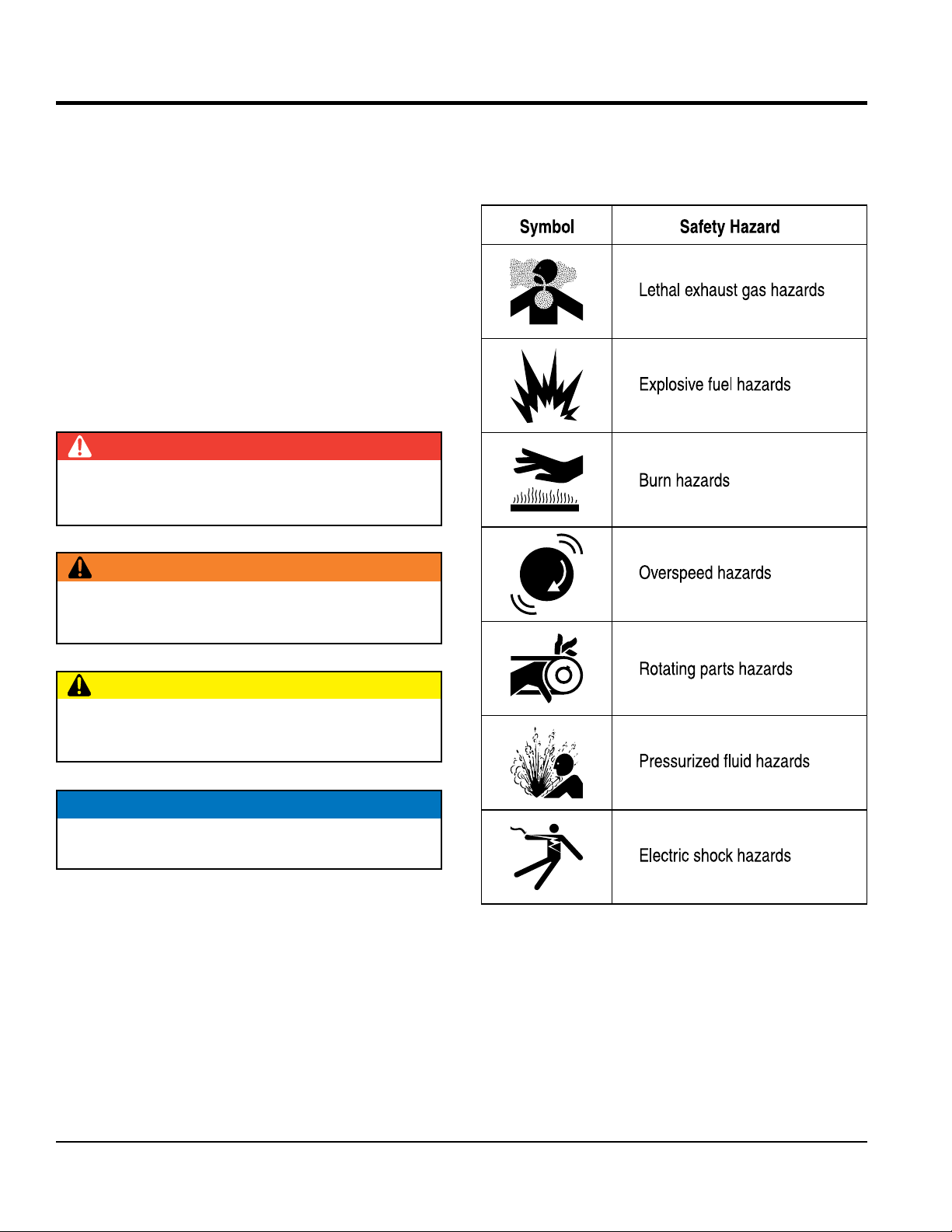
Potential hazards associated with the operation of this
equipment will be referenced with hazard symbols which
may appear throughout this manual in conjunction with
safety messages.
MQP240 GENERATOR • OPERATION AND PARTS MANUAL — REV. #0 (10/23/12) — PAGE 7
SAFETY INFORMATION
GENERAL SAFETY
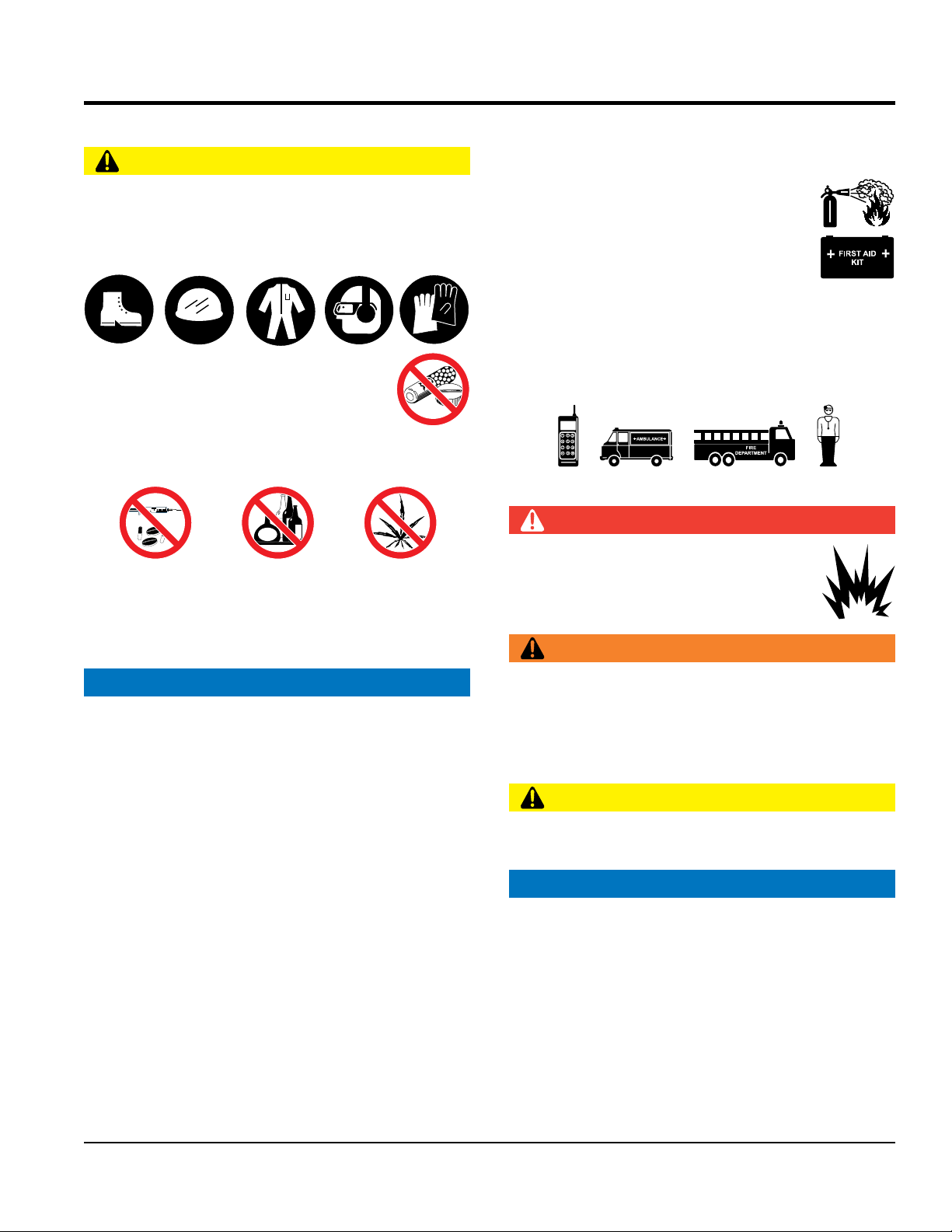
CAUTION
NEVER operate this equipment without proper protective
clothing, shatterproof glasses, respiratory protection,
hearing protection, steel-toed boots and other protective
devices required by the job or city and state regulations.
NEVER operate this equipment when not
feeling well due to fatigue, illness or when
under medication.
NEVER operate this equipment under the infl uence of
drugs or alcohol.
ALWAYS check the equipment for loosened threads or
bolts before starting.
DO NOT use the equipment for any purpose other than
its intended purposes or applications.
NOTICE
This equipment should only be operated by trained and
qualifi ed personnel 18 years of age and older.
Whenever necessary, replace nameplate, operation and
safety decals when they become diffi cult read.
Manufacturer does not assume responsibility for any
accident due to equipment modifi cations. Unauthorized
equipment modifi cation will void all warranties.
NEVER use accessories or attachments that are not
recommended by MQ Power for this equipment. Damage
to the equipment and/or injury to user may result.
ALWAYS know the location of the nearest
fi re extinguisher.
ALWAYS know the location of the nearest
fi rst aid kit.
ALWAYS know the location of the nearest
phone or keep a phone on the job site.
Also, know the
phone numbers of the nearest ambulance, doctor
and
fi re department.
This information will be invaluable in
the case of an emergency.
GENERATOR SAFETY
DANGER
NEVER operate the equipment in an explosive
atmosphere or near combustible materials. An
explosion or fi re could result causing severe
bodily harm or even death.
WARNING
NEVER disconnect any
emergency or safety devices.
These devices are intended for operator safety.
Disconnection of these devices can cause severe injury,
bodily harm or even death. Disconnection of any of these
devices will void all warranties.
CAUTION
NEVER lubricate components or attempt service on a
running machine.
NOTICE
ALWAYS
ensure generator is on level ground before use.
ALWAYS
keep the machine in proper running condition.
Fix damage to machine and replace any broken parts
immediately.
ALWAYS
store equipment properly when it is not being
used. Equipment should be stored in a clean, dry location
out of the reach of children and unauthorized personnel
PAGE 8 —MQP240 GENERATOR • OPERATION AND PARTS MANUAL — REV. #0 (10/23/12)
SAFETY INFORMATION
ENGINE SAFETY
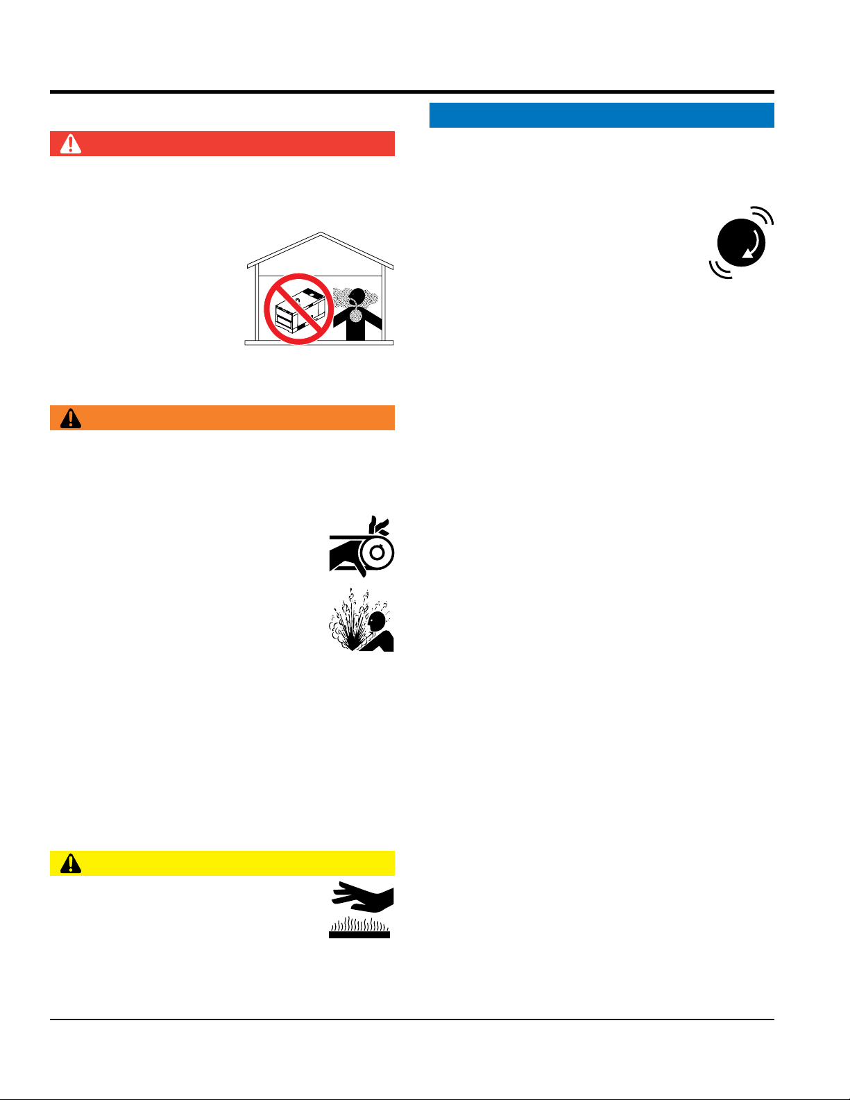
DANGER
The engine fuel exhaust gases contain poisonous carbon
monoxide. This gas is colorless and odorless, and can
cause death if inhaled.
The engine of this equipment
requires an adequate free
fl ow of cooling air. NEVER
operate this equipment in
any enclosed or narrow area
where free fl ow of the air is
restricted. If the air fl ow is
restricted it will cause injury to people and property and
serious damage to the equipment or engine.
WARNING
DO NOT place hands or fingers in s i d e en g i ne
compartment when engine is running.
NEVER operate the engine with heat shields or
guards removed.
Keep fi ngers, hands hair and clothing away
from all moving parts to prevent injury.
DO NOT remove the radiator cap while the
engine is hot. High pressure boiling water
will gush out of the radiator and severely
scald any persons in the general area of
the generator.
DO NOT remove the coolant drain plug while the engine
is hot. Hot coolant will gush out of the coolant tank and
severely scald any persons in the general area of the
generator.
DO NOT remove the engine oil drain plug while the
engine is hot. Hot oil will gush out of the oil tank and
severely scald any persons in the general area of the
generator.
CAUTION
NEVER touch the hot exhaust manifold,
muffl er or cylinder. Allow these parts to cool
before servicing equipment.
NOTICE
NEVER
run engine without an air fi lter or with a dirty air
fi lter. Severe engine damage may occur. Service air fi lter
frequently to prevent engine malfunction.
NEVER tamper with the factory settings
of the engine or engine governor. Damage
to the engine or equipment can result
if operating in speed ranges above the
maximum allowable.
Wet stacking is a common problem with diesel engines
which are operated for extended periods with light or
no load applied. When a diesel engine operates without
suffi cient load (less than 40% of the rated output), it will
not operate at its optimum temperature. This will allow
unburned fuel to accumulate in the exhaust system,
which can foul the fuel injectors, engine valves and
exhaust system, including turbochargers, and reduce
the operating performance.
In order for a diesel engine to operate at peak effi ciency,
it must be able to provide fuel and air in the proper ratio
and at a high enough engine temperature for the engine
to completely burn all of the fuel.
Wet stacking does not usually cause any permanent
damage and can be alleviated if additional load is
applied to relieve the condition. It can reduce the system
performance and increase maintenance. Applying an
increasing load over a period of time until the excess
fuel is burned off and the system capacity is reached
usually can repair the condition. This can take several
hours to burn off the accumulated unburned fuel.
State Health Safety Codes and Public Resources
Codes specify that in certain locations, spark arresters
must be used on internal combustion engines that use
hydrocarbon fuels. A spark arrester is a device designed
to prevent accidental discharge of sparks or fl ames
from the engine exhaust. Spark arresters are qualifi ed
and rated by the United States Forest Service for this
purpose. In order to comply with local laws regarding
spark arresters, consult the engine distributor or the
local Health and Safety Administrator.
MQP240 GENERATOR • OPERATION AND PARTS MANUAL — REV. #0 (10/23/12) — PAGE 9
SAFETY INFORMATION
FUEL SAFETY
DANGER
DO NOT start the engine near spilled fuel or combustible
fl uids. Diesel fuel is extremely fl ammable and its vapors
can cause an explosion if ignited.
ALWAYS refuel in a well-ventilated area, away from
sparks and open fl ames.
ALWAYS use extreme caution when working with
fl ammable liquids.
DO NOT fi ll the fuel tank while the engine is running
or hot.
DO NOT overfi ll tank, since spilled fuel could ignite if it
comes into contact with hot engine parts or sparks from
the ignition system.
Store fuel in appropriate containers, in well-ventilated
areas and away from sparks and fl ames.
NEVER use fuel as a cleaning agent.
DO NOT smok e ar o u n d or ne a r th e
equipment. Fire or explosion could result
from fuel vapors or if fuel is spilled on a
hot engine.
TOWING SAFETY
CAUTION
Check with your local county or state safety
towing regulations, in addition to meeting
Department of Transportation (DOT)
Safety Towing Regulations, before towing
your generator.
Refer to MQ Power trailer manual for additional safety
information.
In order to reduce the possibility of an accident while
transporting the generator on public roads, ALWAYS
make sure the trailer that supports the generator and
the towing vehicle are mechanically sound and in good
operating condition.
ALWAYS shutdown engine before transporting
Make sure the hitch and coupling of the towing vehicle
are rated equal to, or greater than the trailer “gross
vehicle weight rating.”
ALWAYS inspect the hitch and coupling for wear.
NEVER
tow a trailer with defective hitches, couplings, chains, etc.
Check the tire air pressure on both towing vehicle and
trailer.
Trailer tires should be infl ated to 50 psi cold.
Also check the tire tread wear on both vehicles.
ALWAYS make sure the trailer is equipped with a
safety
chain.
ALWAYS properly
attach trailer’s safety chains to towing
vehicle.
ALWAYS
make sure the vehicle and trailer directional,
backup, brake and trailer lights are connected and
working properly.
DOT Requirements include the following:
• Connect and test electric brake operation.
• Secure portable power cables in cable tray with tie
wraps.
The maximum speed for highway towing is 55 MPH
unless
posted otherwise. Recommended off-road towing is not to
exceed 15 MPH or less depending on type of terrain.
Avoid sudden stops and starts. This can cause skidding,
or jack-knifi ng. Smooth, gradual starts and stops will
improve towing.
Avoid sharp turns to prevent rolling.
Trailer should be adjusted to a level position at all times
when towing.
Raise and lock trailer wheel stand in up position when
towing.
Place chock blocks underneath wheel to prevent
rolling
while parked.
Place support blocks
underneath the trailer’s bumper
to prevent tipping while parked.
Use the trailer’s swivel jack to adjust the trailer height to
a level position while parked.
PAGE 10 —MQP240 GENERATOR • OPERATION AND PARTS MANUAL — REV. #0 (10/23/12)
SAFETY INFORMATION
ELECTRICAL SAFETY
DANGER
DO NOT touch output terminals during
operation. Contact with output terminals
during operation can cause electrocution,
electrical shock or burn.
The electrical vol tage requir ed to
operate the generator can cause severe
injury or even death through physical contact with live
circuits. Turn generator and all circuit breakers OFF
before performing maintenance on the generator or
making contact with output terminals.
NEVER insert any objects into the output
recept acles during operation. This is
extremely dangerous. The possibility exists
of electrical shock, electrocution or
death.
Backfeed to a utility system can cause
electrocution and/or property damage.
NEVER connect the generator to a
building’s electrical system without
a transfer switch or other approved
device. All installations should be
performed by a licensed electrician in accordance with
all applicable laws and electrical codes. Failure to do so
could result in electrical shock or burn, causing serious
injury or even death.
Power Cord/Cable Safety
DANGER
NEVER let power cords or cables lay in water.
NEVER stand in water while AC power from the
generator is being transferred to a load.
NEVER use damaged or worn cables or cords when
connecting equipment to generator. Inspect for cuts in
the insulation.
NEVER grab or touch a live power
cord or cable with wet hands. The
possibility exists of electrical shock,
electrocution or death.
Make sure power cables are securely connected to the
generator’s output receptacles. Incorrect connections
may cause electrical shock and dam age to the
generator.
NOTICE
ALWAYS
make certain that proper power or extension
cord has been selected for the job. See Cable Selection
Chart in this manual.
Grounding Safety
DANGER
ALWAYS
make sure that electrical circuits are properly
grounded to a suitable earth ground (ground rod) per
the National Electrical Code (NEC) and local codes
before operating generator.
Severe injury or death by
electrocution
can result from operating an ungrounded
generator.
NEVER use gas piping as an electrical ground.
MQP240 GENERATOR • OPERATION AND PARTS MANUAL — REV. #0 (10/23/12) — PAGE 11
SAFETY INFORMATION
BATTERY SAFETY
DANGER
DO NOT drop the battery. There is a possibility that the
battery will explode.
DO NOT expose the battery to open fl ames,
sparks, cigarettes, etc. The battery contains
combustible gases and liquids. If these
gases and liquids come into contact with a
fl ame or spark, an explosion could occur.
WARNING
ALWAYS wear safety glasses when handling
the battery to avoid eye irritation. The battery
contains acids that can cause injury to the
eyes and skin.
Use well-insulated gloves when picking up the battery.
ALWAYS keep the battery charged. If the battery is not
charged, combustible gas will build up.
ALWAYS recharge the battery in a well-ventilated
environment to avoid the risk of a dangerous concentration
of combustible gasses.
If the battery liquid (dilute sulfuric acid) comes into
contact with clothing or skin, rinse skin or clothing
immediately with plenty of water.
If the battery liquid (dilute sulfuric acid) comes into
contact with eyes, rinse eyes immediately with plenty
of water and contact the nearest doctor or hospital to
seek medical attention.
CAUTION
ALWAYS disconnect the NEGATIVE battery terminal
before performing service on the generator.
ALWAYS keep battery cables in good working condition.
Repair or replace all worn cables.
ENVIRONMENTAL SAFETY
NOTICE
Dispose of hazardous waste properly.
Examples of potentially hazardous waste
are used motor oil, fuel and fuel fi lters.
DO NOT use food or plastic containers to
dispose of hazardous waste.
DO NOT
pour waste, oil or fuel directly onto the ground,
down a drain or into any water source.

PAGE 12 —MQP240 GENERATOR • OPERATION AND PARTS MANUAL — REV. #0 (10/23/12)
SPECIFICATIONS
Table 1. Generator Specifications
Model
MQP240
Type
Revolving field, self ventilated,
open protected type synchronous generator
Armature Connection Star with Neutral
Phase
3
Standby Output
260 KW
Prime Output
240 KW
3Ø Voltage (L-L/L-N)
Voltage Change-Over Bd. at 3Ø 240/139
208Y/120, 220Y/127, 240Y/139
3Ø Voltage (L-L/L-N)
Voltage Change-Over Bd. at 3Ø 480/277
416Y/240, 440Y/254, 480Y/277
Power Factor
0.8
Frequency
60 Hz
Speed
1800 rpm
Aux. AC Power
Single Phase, 60 Hz
Aux. Voltage/Output
4.8 Kw (2.4 kW x 2)
Dry Weight
8,811 lbs. (4,000 kg)
Wet Weight
9,010lbs. (4,091 kg)
Table 2. Engine Specifications
Model
Cummins QSL9-G3 Tier 3
Type
4 cycle, water-cooled, direct injection, turbo-charged
with air to air after-cooler
No. of Cylinders
6 cylinders
Bore x Stroke
4.49 in. x 5.69 in. (114 mm x 145 mm)
Displacement
543 cu. in. (8900 cc)
Rated Output
363 HP at 1800 rpm
Starting
Electric
Coolant Capacity
11.3 gal. (43.0 liters)
Lube Oil Capacity
7.0 gal. (26.5 liters)
Fuel Type
#2 Diesel Fuel
Fuel Consumption
19.0 gal. (72.0 L)/hr at full load 15.5 gal. (58.6 L)/hr at 3/4 load
11.1 gal. (41.9 L)/hr at 1/2 load 5.9 gal. (22.4 L)/hr at 1/4 load
Battery
150 Ah x 2 (24V System)
MQP240 GENERATOR • OPERATION AND PARTS MANUAL — REV. #0 (10/23/12) — PAGE 13
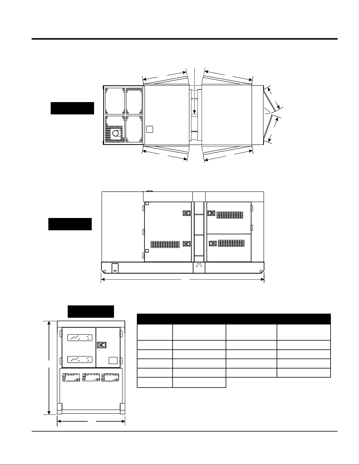
DIMENSIONS
TOP VIEW
SIDE VIEW
FRONT VIEW
A
E
MAXIMUM LIFTING
CAPACITY
16,500 LBS.
(7,484 KG)
F
B
D
C
G
I
H
Figure 1. Dimensions
Table 3. Dimensions
Reference
Letter
Dimension in. (mm) Reference Letter Dimension in. (mm)
A 39.76 in. (1,010 mm) F 43.90 in. (1,115 mm)
B 43.90 in. (1,115 mm) G 149.61 in. (3,800 mm)
C 23.03 in. (585 mm.) H 70.87 in. (1,800 mm)
D 25.20 in. (640 mm) I 55.12 in. (1,400 mm)
E 39.76 in. (1,010 mm)
PAGE 14 —MQP240 GENERATOR • OPERATION AND PARTS MANUAL — REV. #0 (10/23/12)
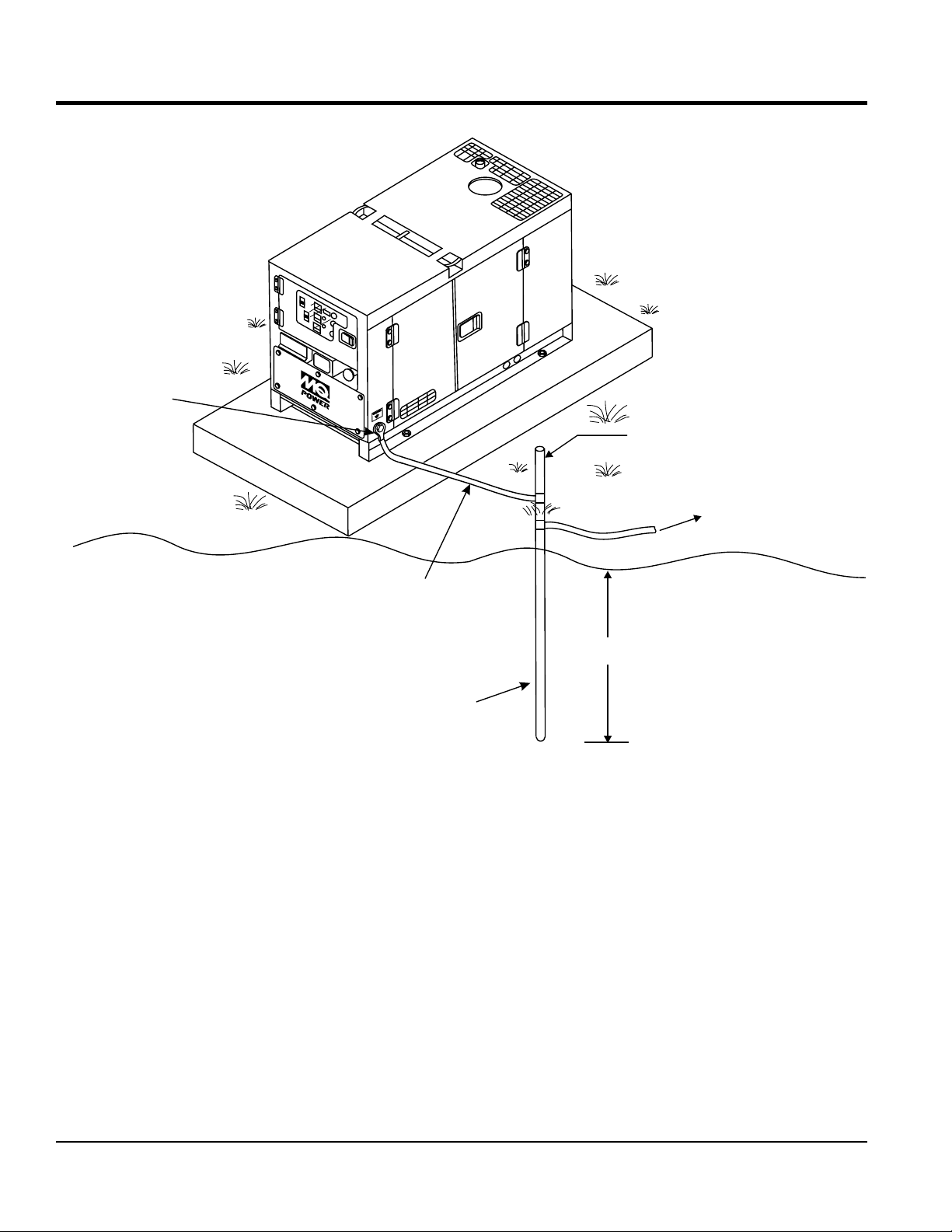
INSTALLATION
GROUND
GROUND ROD
FOR EARTH
GROUND
GROUND CABLE
GENERATOR
GROUND LUG
CONNECT TO
BUILDING
GROUND
8 FT. MINIMUM
REFERENCE
NEC 250-52(C)
Figure 2. Typical Generator Grounding Application

MQP240 GENERATOR • OPERATION AND PARTS MANUAL — REV. #0 (10/23/12) — PAGE 15
INSTALLATION
OUTDOOR INSTALLATION
Install the generator in a area that is free of debris,
bystanders, and overhead obstructions. Make sure the
generator is on secure level ground so that it cannot slide
or shift around. Also install the generator in a manner so
that the exhaust will not be discharged in the direction of
nearby homes.
The installation site must be relatively free from moisture
and dust. All electrical equipment should be protected from
excessive moisture. Failure to do will result in deterioration
of the insulation and will result in shor t circuits and
grounding.
Foreign materials such as dust, sand, lint and abrasive
materials have a tendency to cause excessive wear to
engine and alternator parts.
INDOOR INSTALLATION
Exhaus t gas es from diesel engines are extremely
poisonous. Whenever an engine is installed indoors the
exhaust fumes must be vented to the outside. The engine
should be installed at least two feet from any outside wall.
Using an exhaust pipe which is too long or too small can
cause excessive back pressure which will cause the engine
to heat excessively and possibly burn the valves.
MOUNTING
The generator must be mounted on a solid foundation (such
as concrete) and set firmly on the foundation to isolate
vibration of the generator when it is running. The generator
must set at least 6 inches above the floor or grade level (in
accordance to NFPA 110, Chapter 5-4.1). DO NOT remove
the metal skids on the bottom of the generator. They are
to resist damage to the bottom of the generator and to
maintain alignment.
CAUTION
Pay close attention to ventilation when operating the
generator inside tunnels and caves. The engine exhaust
contains noxious elements. Engine exhaust must be
routed to a ventilated area.
GENERATOR GROUNDING
To guard against electrical shock and possible damage to
the equipment, it is important to provide a good EARTH
ground.
Article 250 (Grounding) of the National Electrical Code
(NEC) provides guide lines for proper grounding and
specifies that the cable ground shall be connected to the
grounding system of the building as close to the point of
cable entry as practical.
NEC ar ticles 250-64(b) and 250-66 set the following
grounding requirements:
1. Use one of the following wire types to connect the
generator to earth ground.
a. Copper - 8 AWG (5.3 mm
2
)
b. Aluminum - 6 AWG (8.4 mm
2
)
2. When grounding the generator (Figure 2) connect the
ground cable between the lock washer and the nut on
the generator and tighten the nut fully. Connect the
other end of the ground cable to earth ground.
3. NEC article 250-52(c) specifies that the earth ground rod
should be buried a minimum of 8 ft. into the ground.
NOTICE
When connecting the generator to any buildings
electrical system ALWAYS consult with a licensed
electrician.
NOTICE
This generator has a permanent bonding conductor
between the generator stator windings and the frame.

PAGE 16 —MQP240 GENERATOR • OPERATION AND PARTS MANUAL — REV. #0 (10/23/12)
GENERATOR
The MQP240 generator (Figure 3) is designed as a high
quality portable (requires a trailer for transport) power
source for telecom sites, lighting facilities, power tools,
submersible pumps and other industrial and construction
machinery.
ENGINE OPERATING PANEL
The “Engine Operating Panel” is provided with the following:
Tachometer
Emergency Stop Switch
Water Temperature Gauge
Oil Pressure Gauge
Charging Ammeter Gauge
Fuel Level Gauge
Engine Speed Switch
Battery Switch
Engine Alarm Lamps (4)
GENERATOR CONTROL PANEL
The “Generator Control Panel” is provided with the following:
Frequency Meter (Hz)
AC Ammeter (Amps)
AC Voltmeter (Volts)
Ammeter Change-Over Switch
Voltmeter Change-Over Switch
Voltage Regulator
Panel Light/Panel Light Switch
3-Pole, 800 amp Main Circuit Breaker
“Control Box” (located behind the Gen. Control Panel)
• Automatic Voltage Regulator
• Current Transformer
• Over-Current Relay
• Starter Relay
• Engine Controller (Computer Controlled)
OUTPUT TERMINAL PANEL
The “Output Terminal Panel” is provided with the following:
Three 120/240V output receptacles (CS-6369), 50A
Three auxiliary circuit breakers, 50A
Two 120V output receptacles (GFCI), 20A
Two GFCI circuit breakers, 20A
Eight output terminal lugs (3Ø power)
Battery Charger (Optional)
Water Heater (Optional)
OPEN DELTA EXCITATION SYSTEM
Each generator is equipped with the state of the art “Open-
Delta” excitation system. The open delta system consist
of an electrically independent winding wound among
stationary windings of the AC output section.
There are four connections of the open delta A, B, C and
D. During steady state loads, the power from the voltage
regulator is supplied from the parallel connections of A to
B, A to D, and C to D. These three phases of the voltage
input to the voltage regulator are then rectified and are the
excitation current for the exciter section.
When a heavy load, such as a motor starting or a short
circuit occurs, the automatic voltage regulator (AVR)
switches the configuration of the open delta to the series
connection of B to C. This has the effect of adding the
voltages of each phase to provide higher excitation to the
exciter section and thus better voltage response during the
application of heavy loads.
The connections of the AVR to the AC output windings are
for sensing only. No power is required from these windings.
The open-delta design provides virtually unlimited excitation
current, offering maximum motor starting capabilities. The
excitation does not have a “fixed ceiling” and responds
according the demands of the required load.
ENGINE
Both generators are powered by a 6 cylinder, 4-cycle water
cooled, direct injection, turbocharged, charge air cooled
Cummins QSL9-G3 diesel engine. This engine is designed
to meet every performance requirement for the generator.
Reference Table 2 for engine specifications.
In keeping with MQ Power’s policy of constantly improving
its products, the specifications quoted herein are subject
to change without prior notice.
ELECTRIC GOVERNOR SYSTEM
The electric governor system controls the RPMs of the engine.
When the engine demand increases or decreases, the
governor system regulates the frequency variation to ±.25%.
EXTENSION CABLES
When electric power is to be provided to various tools or
loads at some distance from the generator, extension cords
are normally used. Cables should be sized to allow for
distance in length and amperage so that the voltage drop
between the generator and point of use (load) is held to
a minimum. Use the cable selection chart (Table 6) as a
guide for selecting proper extension cable size.
GENERAL INFORMATION
MQP240 GENERATOR • OPERATION AND PARTS MANUAL — REV. #0 (10/23/12) — PAGE 17
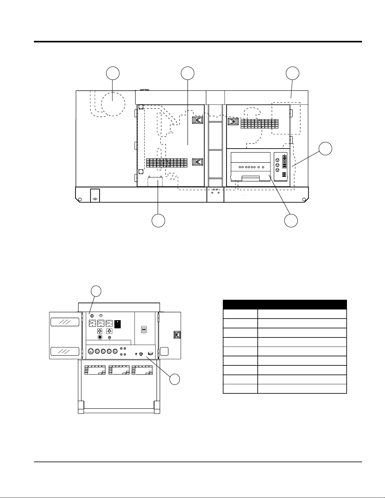
MAJOR COMPONENTS
6 5
4
321
300
U
V
W
O
GND
AUTO
MANUAL
OFF/RESET
LOW OILPRESSURE
HIGH COOLANTTEMPERATURE
OVERCRANK
OVERSPEED
ENGINE RUNNING
MOOOOO-20001Q
7
8
Table 4. Generator Major Components
ITEM NO. DESCRIPTION
1 Muffler Assembly
2 Engine Assembly
3 Enclosure Assembly
4 Generator Assembly
5 Output Terminal Assembly
6 Battery Assembly
7 Generator Control Panel Assembly
8 Engine Operating Panel Assembly
Figure 3. Major Components

PAGE 18 —MQP240 GENERATOR • OPERATION AND PARTS MANUAL — REV. #0 (10/23/12)
GENERATOR CONTROL PANEL
Figure 4. Generator Control Panel
The definitions below describe the controls and functions
of the Generator Control Panel (Figure 4).
1. Pilot Lamp — Indicates the system is running.
2. Panel Light — Normally used in dark areas or at night
time. When activated, panel lights will illuminate. When
the generator is not in use be sure to turn the panel
light switch to the OFF position.
3. AC Voltmeter — Indicates the output voltage present
at the U,V, and W Output Terminal Lugs.
4. Auto On/Off Engine Controller (MPEC) —
This controller has a vertical row of status LED’s (inset),
that when lit, indicate that an engine malfunction (fault)
has been detected. When a fault
has been detected the engine
controller will evaluate the fault
and all major faults will shutdown
the generator. During cranking
cycle, The MPEC will attempt to
crank the engine for 10 seconds
before disengaging.
If the engine does not engage (start) by the third
attempt, the engine will be shutdown by the engine
controller’s Over Crank Protection mode. If the
engine engages at a speed (RPM’s) that is not safe,
the controller will shutdown the engine by initializing
the Over Speed Protection mode.
5. Main Circuit Breaker — This three-pole, 800 amp
main breaker is provided to protect the U,V, and W
Output Terminal Lugs from overload.
6. Voltmeter Change-Over Switch — This switch allows
the AC voltmeter to indicate phase to phase voltage
between any two phases of the output terminals or to
be switched off.
7. Voltage Regulator Control — Allows ±15% manual
adjustment of the generator’s output voltage.
8. Panel Light Switch — When activated will turn on
control panel light.
9. Ammeter Change-Over Switch — This switch allows
the AC ammeter to indicate the current flowing to the load
connected to any phase of the output terminals, or to be
switched off. This switch does not effect the generator
output in any fashion, it is for current reading only.
10. AC Ammeter — Indicates the amount of current the
load is drawing from the generator per leg selected by
the ammeter phase-selector switch.
11. Frequency Meter — Indicates the output frequency
in hertz (Hz). Normally 60 Hz

MQP240 GENERATOR • OPERATION AND PARTS MANUAL — REV. #0 (10/23/12) — PAGE 19
GENERATOR CONTROL PANEL
MPEC Control Switch — This switch controls the
running of the unit. If this switch is set to the OFF/RESET
position, the unit will not run. When this switch is set to the
manual position, the generator will start immediately.
If the generator is to be connected to a building’s AC
power source via a transfer switch (isolation), place the
switch in the AUTO position. In this position, should an
outage occur, the automatic transfer switch (ATS) will
start the generator automatically via the generator’s auto-
start contacts conn ected to the ATS’s start contacts.
Please refer to your ATS installation manual for further
instructions for the correct installation of the auto-start
contacts of the geerator to the ATS.
Low Oil Pressure — Indicates the engine pressure
has fallen below a safe operating level. The oil pressure
is detected using variable resistive values from the
oil pressure sending unit. This is considered a major
fault.
High Coolant Temperature — Indicates the engine
temperature has exceeded a safe operating level. The
engine temperature is detected using variable resistive
values from the temperature sending unit. This is
considered a major fault.
Overcrank Shutdown — Indicates the unit has
attempted to star t a pre- programmed number of
timesand has failed to start. The number of cycles and
duration are programmable. It is pre-set at 3 cycles with
a 10-second duration. This is considered a major fault.
Overspeed Shutdown — Indicates the engine is running
at an unsafe speed. This is considered a major fault.
Engine Running — Indicates that engine is running at
a safe operating speed.
Locat ed behind the generat or control panel is the
Generator Control Box. This box contains some of the
necessary electronic components required to make the
generator function.
The Control Box is equipped with the following major
components:
Over-Current Relay
Voltage Rectifier (AVR)
Starter Relay
Current Transformer
Voltage Change-Over Board
Three Phase Circuit Breaker
NOTICE
Remember the overcurrent relay monitors the current
flowing from the U,V, and W Output Terminal Lugs
to the load.
In the event of a short circuit or over current condition,
it will automatically trip the 800 amp main breaker.
To restore power to the Output Terminal Panel, press
the reset button on the overcurrent relay and place the
main circuit breaker in the closed position (ON).
PAGE 20 —MQP240 GENERATOR • OPERATION AND PARTS MANUAL — REV. #0 (10/23/12)
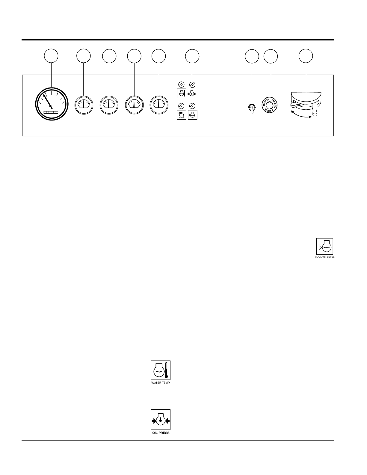
ENGINE OPERATING PANEL
The definitions below describe the controls and functions
of the Engine Operating Panel (Figure 5).
1. Tachometer — Indicates engine speed in RPM’s for 60
Hz operation. This meter should indicate 1800 RPM’s
when the rated load is applied. In addition a built in hour
meter will record the number of operational hours that
the generator has been in use.
2. Oil Pressure Gauge — During normal operation this
gauge be should read between 28 to 85 psi. (193~586
kPa). When starting the generator the oil pressure may
read a little higher, but after the engine warms up the oil
pressure should return to the correct pressure range.
3. Water Temperature Gauge — During normal operation
this gauge be should read between 167° and 203°F
(75°~95°C).
4. Charging Ammeter Gauge — Indicates the current
being supplied by the engine’s alternator which
provides current for generator’s control circuits and
battery charging system.
5. Fuel Gauge — Indicates amount of diesel fuel
available.
6. Engine Warning Lamps — There are four engine
warning lamps, they are defined as follows:
a. Overheat Lamp — This lamp goes ON
when the cooling water temperature rises
abnormally. If the lamp goes ON during
normal operation of the generator, the
emergency shutdown device will stop the
engine automatically.
b. Low Oil Pressure Lamp — During
normal operation of the generator this
lamp should remain OFF. When the
Auto-OFF/Reset-Manual switch is set to the
MANUAL position to start the engine, the lamp will
be lit. When the oil pressure rises after start-up the
lamp will go OFF. If this lamp is ever lit (ON) during
normal operation of the generator, the emergency
shutdown device will stop the engine automatically.
c. Air Filter Alarm — When the air filter element is
clogged, this lamp goes ON indicating the element
should be immediately cleaned or replaced.
d. Coolant Level Alarm — This lamp
goes ON when the coolant level is low.
If this lamp goes ON while the engine is
in operation, the emergency shutdown
device will automatically stop the engine.
7. Engine Speed Switch — This switch controls the
speed of the engine (low/high).
8. Emergency Stop Button — Push this button inward
to stop the engine in the event of an emergency. DO
NOT use this button as a means of stopping the engine.
9. Battery Switch — This switch should be set to the ON
position during normal operation. When the engine has
been stop, place this switch in the OFF position. DO
NOT turn this switch during normal operation, it could
cause damage to the electrical equipment.
Figure 5. Engine Operating Panel
OFF
ON
OILPRESS.
WATERTEMP.
1 2
3 4 5
6
9
AIR FILTER COOLANTLEVEL
7
8

MQP240 GENERATOR • OPERATION AND PARTS MANUAL — REV. #0 (10/23/12) — PAGE 21
NOTES
PAGE 22 —MQP240 GENERATOR • OPERATION AND PARTS MANUAL — REV. #0 (10/23/12)
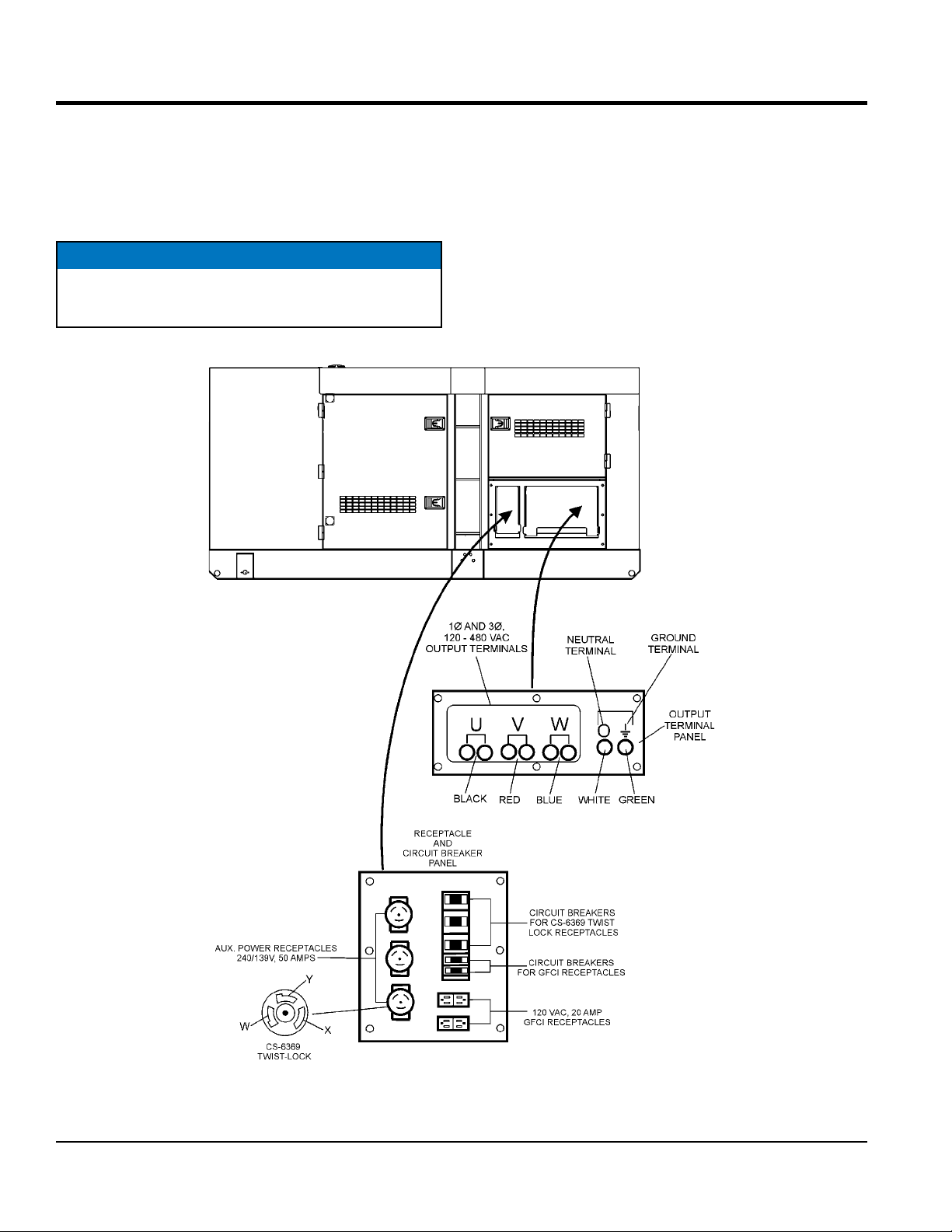
OUTPUT TERMINAL PANEL FAMILIARIZATION
OUTPUT TERMINAL PANEL
The Output Terminal Panel (Figure 6) shown below is
located on the right-hand side (left from control panel) of
the generator. Lift up on the cover to gain access to
receptacles and terminal lugs.
NOTICE
Terminal legs “O” and “Ground” are considered bonded
grounds
OUTPUT TERMINAL FAMILIARIZATION
The “Output Terminal Panel ” (Figure 6) is provided with
the following:
Three (3) 240/139V output receptacles @ 50 amp
Three (3) Circuit Breakers @ 50 amps
Two (2) 120V GFCI receptacles @ 20 amp
Two (2) GFCI Circuit Breakers @ 20 amps
Eight (8) Output Terminal Lugs ( U, V, W, O, Ground)
Figure 6. Output Terminal Panel

MQP240 GENERATOR • OPERATION AND PARTS MANUAL — REV. #0 (10/23/12) — PAGE 23
OUTPUT TERMINAL PANEL FAMILIARIZATION
120 VAC GFCI Receptacles
There are two 120 VAC, 20 amp GFCI (Duplex Nema 5-20R)
receptacles provided on the output terminal panel. These
receptacles can be accessed in any voltage change-over
board configuration. Each receptacle is protected by a 20
amp circuit breaker. These breakers are located directly
above the GFCI receptacles. Remember the load output
(current) of both GFCI receptacles is dependent on the
load requirements of the U, V, and W output terminal lugs.
Pressing the reset button resets the GFCI receptacle after
being tripped. Pressing the test button (See Figure 7) in
the center of the receptacle will check the GFCI function.
Both receptacles should be tested at least once a month.
Figure 7. G.F.C.I. Receptacle
Twist Lock Dual Voltage 120/240 VAC Receptacles
There are three 120/240V, 50 amp auxiliary twist-lock (CS-
6369) receptacles (Figure 8) provided on the output
terminal panel. These receptacles can only be accessed
when the voltage change-over board is configured for
single-phase 240/120 application
Figure 8. 120/240V Twist-Lock Auxiliary
Receptacles
Each auxiliary receptacle is protected by a 50 amp circuit
breaker. These breakers are located directly above the
GFCI receptacles. Remember the load output (current) on
all three receptacles is dependent on the load requirements
of the output terminal lugs.
Turn the voltage regulator control knob (Figure 9) on the
control panel to obtain the desired voltage. Turning the knob
clockwise will increase the voltage, turning the knob
counter-clockwise will decrease the voltage.
Figure 9. Voltage Regulator Control Knob
PAGE 24 —MQP240 GENERATOR • OPERATION AND PARTS MANUAL — REV. #0 (10/23/12)
OUTPUT TERMINAL PANEL FAMILIARIZATION
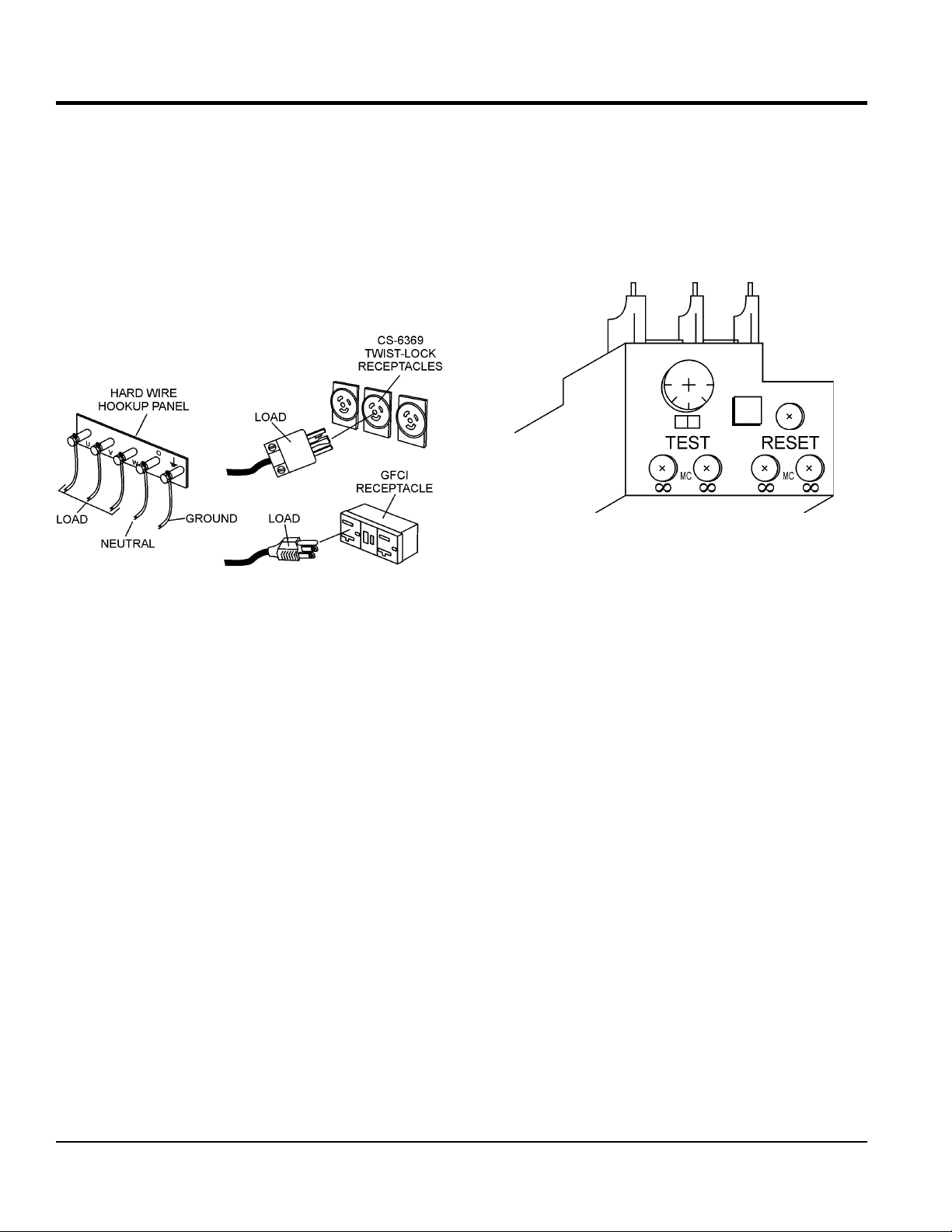
Connecting Loads
Loads can be connected to the generator by the Output
Terminal Lugs or the convenience receptacles (Figure 10).
Make sure to read the operation manual before attempting
to connect a load to the generator.
To protect the output terminals from overload, a 3-pole,
800A main circuit breaker is provided. Make sure to switch
ALL circuit breakers to the OFF position prior to starting
the engine.
Figure 10. Connecting Loads
Over Current Relay
An over current relay (Figure 11) is connected to the main
circuit breaker. In the event of an overload, both the circuit
breaker and the over current relay may trip. If the circuit
breaker can not be reset, the reset button on the over
current relay must be pressed. The over current relay is
located in the control box.
Figure 11. Over Current Relay
MQP240 GENERATOR • OPERATION AND PARTS MANUAL — REV. #0 (10/23/12) — PAGE 25
LOAD APPLICATION
SINGLE PHASE LOAD
Always be sure to check the nameplate on the generator
and equipment to insure the wattage, amperage, frequency,
and voltage requirements are satisfactorily supplied by the
generator for operating the equipment.
Generally, the wattage listed on the nameplate of the
equipment is its rated output. Equipment may require
130—150% more wattage than the rating on the nameplate,
as the wattage is influenced by the efficiency, power factor
and starting system of the equipment.
WATTS = VOLTAGE x AMPERAGE
The power factor of this generator is 0.8. See Table 5 below
when connecting loads.
Table 6. Cable Selection (60 Hz, Single Phase Operation)
Current
in
Amperes
Load in Watts Maximum Allowable Cable Length
At 100
Volts
At 200
Volts
#10 Wire #12 Wire #14 Wire #16 Wire
2.5 300 600 1000 ft. 600 ft. 375 ft. 250 ft.
5 600 1200 500 ft. 300 ft. 200 ft. 125 ft.
7.5 900 1800 350 ft. 200 ft. 125 ft. 100 ft.
10 1200 2400 250 ft. 150 ft. 100 ft.
15 1800 3600 150 ft. 100 ft. 65 ft.
20 2400 4800 125 ft. 75 ft. 50 ft.
CAUTION: Equipment damage can result from low voltage
NOTICE
If wattage is not given on the equipment’s name plate,
approximate wattage may be determined by multiplying
nameplate voltage by the nameplate amperage.
Table 5. Power Factor By Load
Type of Load Power Factor
Single-phase induction motors 0.4-0.75
Electric heaters, incandescent lamps 1.0
Fluorescent lamps, mercury lamps 0.4-0.9
Electronic devices, communication
equipment
1.0
Common power tools 0.8
THREE PHASE LOAD
When calculating the power requirements for 3-phase
power use the following equation:
An inadequate size connecting cable which cannot carry the
required load can cause a voltage drop which can burn out
the appliance or tool and overheat the cable. See Table 6.
When conn ecting a resistan ce load suc h as an
incandescent lamp or electric heater, a capacity of up to
the generating set’s rated output (kW) can be used.
When connecting a fluorescent or mercury lamp, a
capacity of up to the generating set’s rated output (kW)
multiplied by 0.6 can be used.
When connecting an electric drill or other power tools,
pay close attention to the required starting current
capacity.
When connecting ordinary power tools, a capacity of up to
the generating set’s rated output (kW) multiplied by 0.8 can
be used.
NOTICE
If 3Ø load (kVA) is not given on the equipment
nameplate, approximate 3Ø load may be determined
by multiplying voltage by amperage by 1.732
NOTICE
Motors and motor-driven equipment draw much greater
current for starting than during operation.
DANGER
Before connecting this generator to any building’s
electrical system, a licensed electrician must install
an isolation (transfer) switch. Serious damage to
the building’s electrical system may occur without this
transfer switch.
PAGE 26 —MQP240 GENERATOR • OPERATION AND PARTS MANUAL — REV. #0 (10/23/12)
GENERATOR OUTPUTS
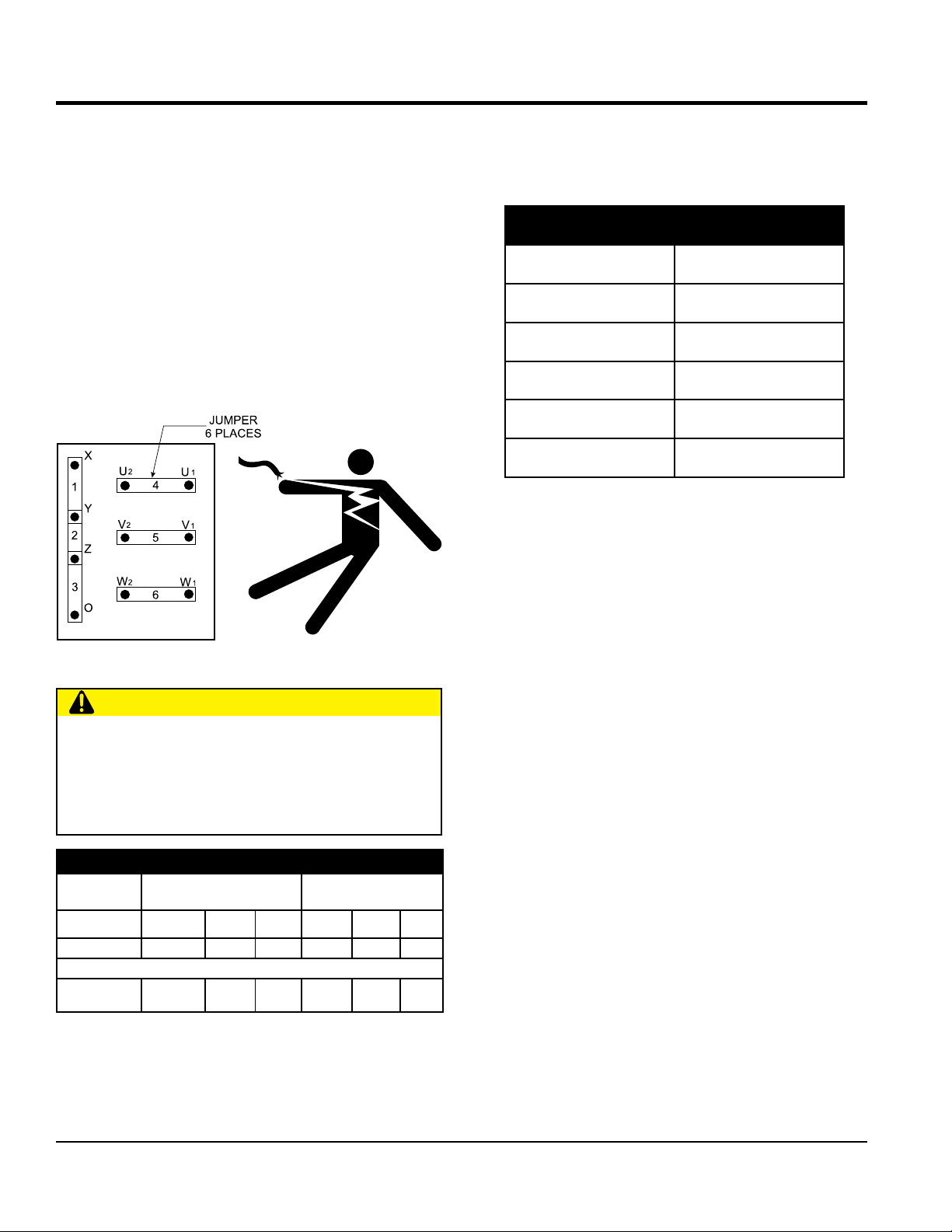
GENERATOR OUTPUT VOLTAGES
A wide range of voltages are available to supply voltage
for many different applications. Voltages are selected by
applying jumpers (6) to the voltage change-over board
(Figure 12). To obtain some of the voltages as listed in
Table 7 (see below) will require a fine adjustment using
the voltage regulator (VR) control knob located on the
control panel.
Voltage Change-Over Board
The voltage change-over board (Figure 12) is located on
the control box, behind the generator control panel. This
board has been provided for ease of voltage selection.
Figure 12. Voltage Change-Over Board
CAUTION
NEVER attempt to place jumper plates on the voltage
change-over board while the generator is in operation.
There exist the possibility of electrocution, electrical
shock or burn, which can cause severe bodily harm
or even death!
Table 7. Voltages Available
UVWO Output
Terminal Lugs
Voltage Change-Over Board
3-Phase 240/139V Position
Voltage Change-Over Board
3-Phase 480/270V Position
3Ø
Line-Line
208V 220V 240V 416V 440V 480V
1Ø Line-Neutral 120V 127V 139V 240V 254V 277V
Voltage Change-Over Board Single-Phase 240/120V Position
1Ø Line-Neutral/
Line-Line
120V
Line-Neutral
N/A N/A
240V
Line-Line
N/A N/A
Maximum Amps
Table 8 shows the maximum amps the generator can
provide. DO NOT exceed the maximum amps as listed.
Table 8. Generator Maximum Amps
Model MQP240
Rated Voltage Maximum Amps
Single Phase 120 Volt 666.7 amps (4 wire)
Single Phase 240 Volt 333.3 amps (4 wire)
Three Phase 240 Volt 722 amps
Three Phase 480 Volt 361 amps
MQP240 GENERATOR • OPERATION AND PARTS MANUAL — REV. #0 (10/23/12) — PAGE 27
GENERATOR OUTPUTS/GAUGE READING
HOW TO READ TH E AC AMMETER AND AC
VOLTAGE GAUGES
The AC ammeter and AC voltmeter gauges are controlled
by the AC ammeter and AC voltmeter change-over
switches.
Both of these switches are located on the control panel and
DO NOT effect the generator output. They are provided to
help observe how much power is being supplied, produced
at the UVWO terminals lugs.
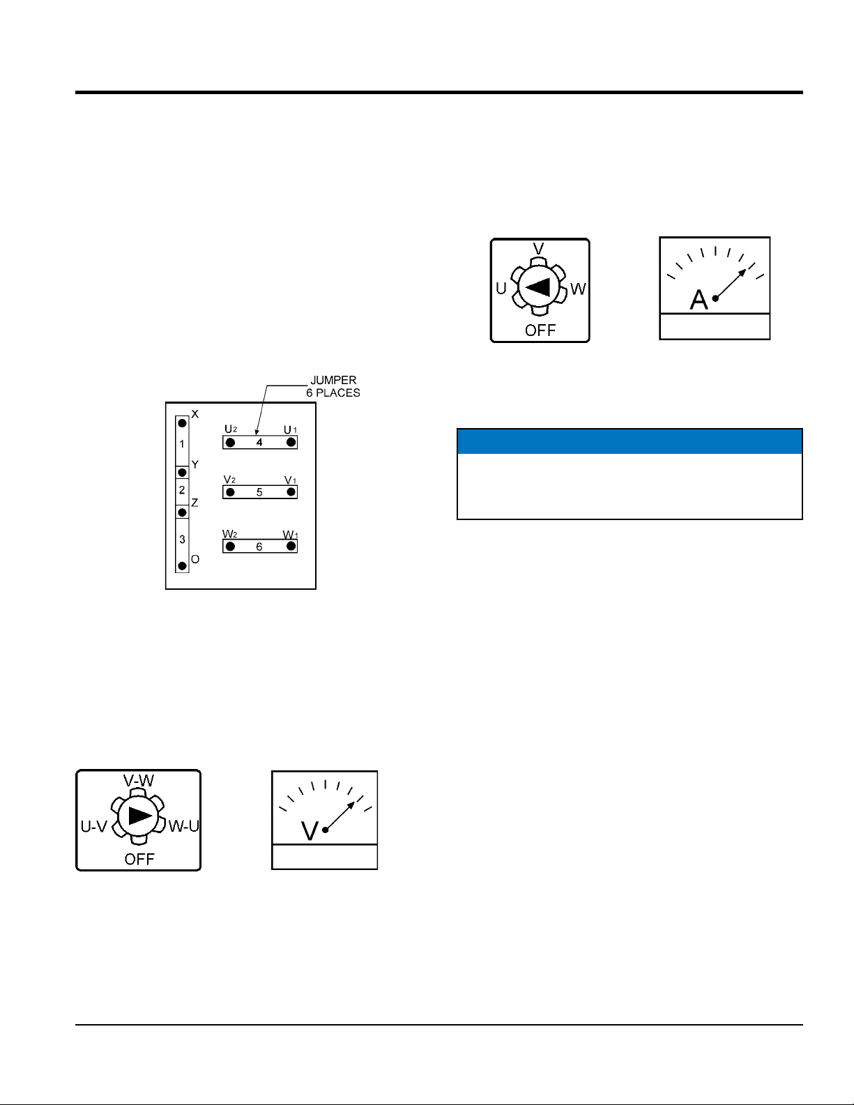
Before taking a reading from either gauge, configure the
Voltage Change-Over Board (Figure 13) which produces
the desired output voltage.
Figure 13. Voltage Change-Over Board
240/3
Ø Position
AC Voltmeter Gauge Reading
Place the AC Voltmeter Change-Over Switch (Figure 14)
in the W-U position and observe the phase to phase voltage
reading between the W and U terminals as indicated on
the AC Voltmeter Gauge (Figure 15).
Figure 14. AC Voltmeter
Change-Over Switch
Figure 15. AC Voltmeter Gauge
(Volt reading on W-U Lug)
AC Ammeter Gauge Reading
Place the AC Ammeter Change-Over Switch (Figure 16)
in the U position and observe the current reading (load
drain) on the U terminal as indicated on the AC Ammeter
Gauge (Figure 17). This process can be repeated for
terminals V and W.
Figure 16. AC Ammeter
Change-Over Switch
Figure 17. AC Ammeter
(Amp reading on U Lug)
NOTICE
The ammeter gauge will only show a reading when
the Output Terminal Lugs are connected to a load
and in use.
PAGE 28 —MQP240 GENERATOR • OPERATION AND PARTS MANUAL — REV. #0 (10/23/12)
OUTPUT TERMINAL PANEL CONNECTIONS
UVWO TERMINAL OUTPUT VOLTAGES
Various output voltages can be obtained using the UVWO
output terminal lugs. The voltages at the terminals are
dependent on the placement of the jumpers plates (6) on
the Voltage Change-Over Board and the adjustment of
the Voltage Regulator Control Knob.
Remember the voltage change-over board determines the
range of the output voltage and can be configured in two
different positions that provide 6 different output voltages
at the UVWO output terminals. The generator is shipped
from the factory in the 240V configuration. The voltage
regulator (VR) allows the user to increase or decrease the
selected voltage.
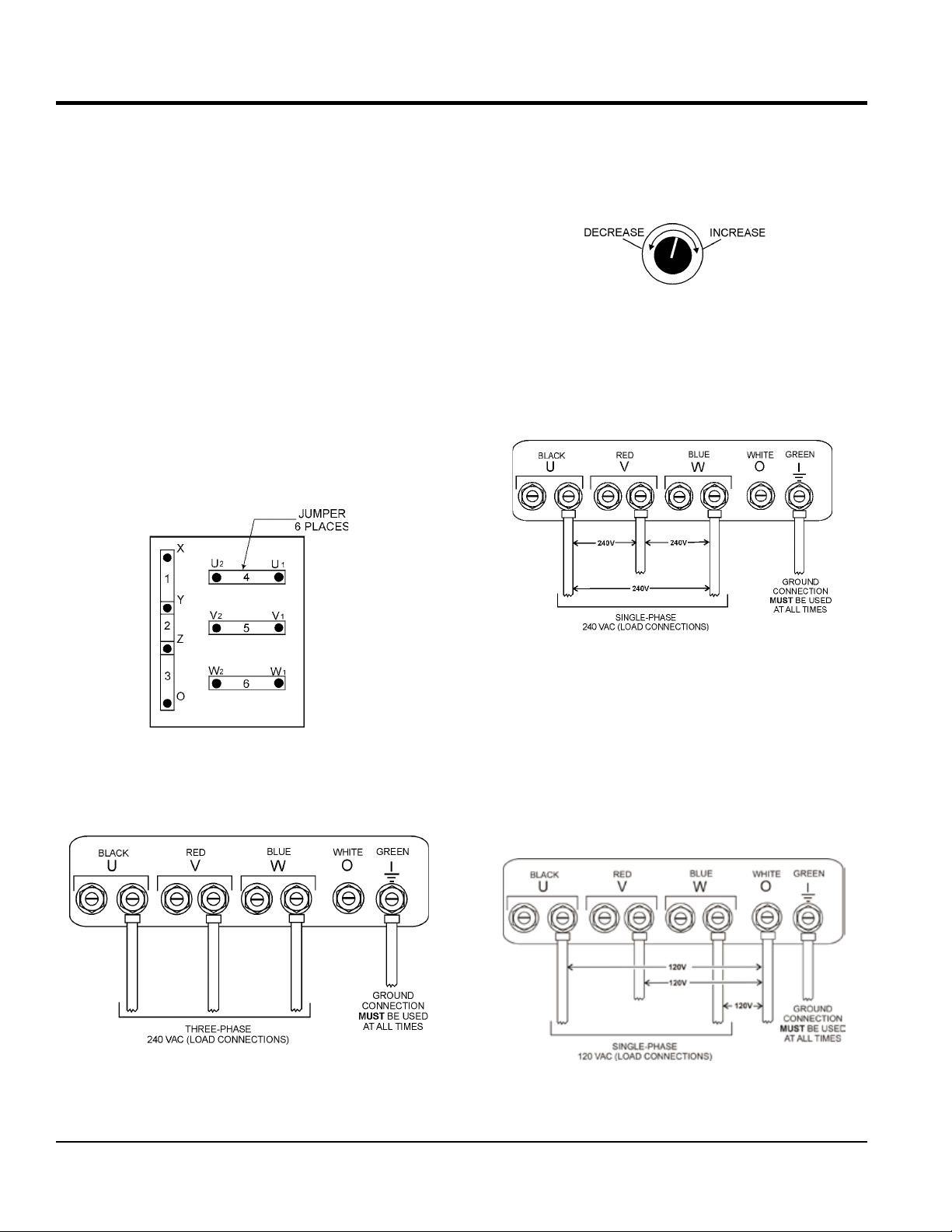
3Ø-240V UVWO Terminal Output Voltages
1. Jumper the voltage change-over board for 240V
operation as shown in Figure 18.
Figure 18. Voltage Change-Over Board 240V
Configuration
2. Connect the load wires to the UVWO terminals as
shown in Figure 19.
Figure 19. UVWO Terminal Lugs
3. Turn the voltage regulator knob (Figure 20) clockwise
to increase voltage output, turn counterclockwise to
decrease voltage output. Use voltage regulator
adjustment knob whenever fine tuning of the output
voltage is required
Figure 20. Voltage Regulator Knob
1Ø-240V UVWO Terminal Output Voltages
1. Make sure the voltage change-over board is jumpered
for 240V operation as shown in Figure 18.
2. Connect the load wires to the UVWO terminals as
shown in Figure 21.
Figure 21. UVWO Terminal Lugs 1Ø-240V
Connections
1Ø-120V UVWO Terminal Output Voltages
1. Make sure the voltage change-over board is jumpered
for 240V operation as shown in Figure 18.
2. Adjust voltage regulator knob (Figure 20) for an output
of 208V to obtain 120V at the UVWO terminals.
3. Connect the load wires to the UVWO terminals as
shown in Figure 22.
Figure 22. UVWO Terminal Lugs 1Ø-120V
Connections
 Loading...