


LS500

OPERATION AND PARTS MANUAL
SERIES
MODELS LS400/LS500
CONCRETE PUMPS
(DEUTZ F4L2011, BF4L2011 DIESEL ENGINES)
Revision #6 (09/19/11)
To find the latest revision of this
publication, visit our website at:
www.multiquip.com
THIS MANUAL MUST ACCOMPANY THE EQUIPMENT AT ALL TIMES.
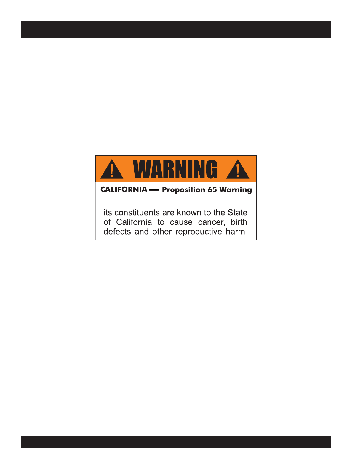
LS400/LS500 PUMP — PROPOSITION 65 WARNING
Proposition 65 W arning
Diesel engine exhaust and some of
PAGE 2 — MAYCO LS400/LS500 PUMP — OPERATION AND PARTS MANUAL — REV. #6 (09/19/11)

NOTES
MAYCO LS400/LS500 PUMP — OPERATION AND PARTS MANUAL — REV. #6 (09/19/11) — PAGE 3
LS400/LS500 PUMP —TABLE OF CONTENTS
MAYCO LS400/LS500
CONCRETE PUMPS
Proposition 65 Warning ............................................. 2
Table of Contents ...................................................... 4
Parts Ordering Procedures ...................................... 5
Safety Message Alert Symbols .............................. 6-7
Rules for Safe Operation .....................................8-10
Specifications .......................................................... 12
Dimensions ............................................................. 13
Important Hand Signals .......................................... 14
General Information ...........................................15-16
How it Works ........................................................... 17
Pump Components ............................................ 18-19
Digital Control Panel Components .......................... 20
Digital Readout Screen ........................................... 21
Engine Components ............................................... 22
Inspection ........................................................... 23-25
Set-Up ..................................................................... 26
Start-Up Procedure ................................................. 27
Operation ...........................................................28-31
Pumping Information .......................................... 32-35
Maintenance (Pump) .........................................36-43
Maintenance (Trailer) ......................................... 44-46
Trailer Safety Guidelines .................................... 47-61
Troubleshooting (Pump)..................................... 62-64
Troubleshooting (Engine) ........................................ 65
Troubleshooting (Brake System)............................. 66
Troubleshooting (Electrical) ............................... 67-69
Wiring Diagram (Control Box) ............................ 70-73
Wiring Diagram (Optional Hopper Vibrator) ............ 74
Hydraulic System Diagram ..................................... 75
Manifold Block Ports ............................................... 76
Appendix - Concrete Mix Information ................77-78
Appendix - Slump Test Procedure........................... 79
Appendix - Recommended Shotcrete System ...... 80-81
Appendix - Recommended Shotcrete Accessories .... 82-83
Explanation Of Codes In Remarks Column ............ 84
Suggested Spare Parts ........................................... 85
COMPONENT DRACOMPONENT DRA
COMPONENT DRA
COMPONENT DRACOMPONENT DRA
Name Plate and Decals ..................................... 86-89
Frame Assy. ....................................................... 90-91
Axle Assy. ........................................................... 92-93
Brake Line Assy. ................................................ 94-95
Brake Lights Assy. .............................................. 96-97
Trailer Hitch Assy. ............................................... 98-99
Battery Assy. ..................................................100-101
Hopper Assy. .................................................. 102-103
Hopper Attachment Assy. .............................. 104-105
Hopper Interior Assy. ..................................... 106-107
Shuttle Cylinder Assy. .................................... 108-109
Lubrication Pistons Assy. ............................... 110-111
Fuel Tank Assy. .............................................. 112-115
Heat Exchanger Assy. .................................... 116-117
Accumulator Assy........................................... 118-119
Remixer Control Assy. .................................... 120-121
Lubrication Panel Assy. .................................. 122-123
Engine Cover Assy. ........................................ 124-125
Hydraulic Tank Assy. ...................................... 126-127
Engine Assy. ................................................... 128-129
Throttle Assy. ................................................. 130-131
Water Separator Assy. ................................... 132-133
Hydraulic Pump Assy. .................................... 134-135
Manifold Assy. ................................................ 136-137
Control Box Assy. ...........................................138-139
Control Box Harness Assy. ............................ 140-141
Remote Control Cable Assy. .......................... 142-143
Hydraulic Stabilizer Assy. (Optional) .............. 144-145
Terms and Conditions of Sale - Parts ................... 146
Mayco Pump Warranty.......................................... 147
Specification and part number are subject
to change without notice.
WINGSWINGS
WINGS
WINGSWINGS
PAGE 4 — MAYCO LS400/LS500 PUMP — OPERATION AND PARTS MANUAL — REV. #6 (09/19/11)
PARTS ORDERING PROCEDURES
Ordering parts has never been easier!
Choose from three easy options:
January 1
Effective:
st
, 2006
Best Deal!
Order via Internet (Dealers Only):
Order parts on-line using Multiquip’s SmartEquip website!
N View Parts Diagrams
N Order Parts
N Print Specification Information
Goto www.multiquip.com and click on
Order Par ts
Order via Fax (Dealers Only):
All customers are welcome to order parts via Fax.
Domestic (US) Customers dial:
1-800-6-PARTS-7 (800-672-7877)
Non-Dealer Customers:
Contact your local Multiquip Dealer for
parts or call 800-427-1244 for help in
locating a dealer near you.
to log in and save!
Order via Phone:
If you have an MQ Account, to obtain a Username
and Password, E-mail us at: parts@multiquip.
com.
To obtain an MQ Account, contact your
District Sales Manager for more information.
Use the internet and qualify for a 5% Discount
on Standard orders for all orders which include
complete part numbers.*
Note: Discounts Are Subject To Change
Fax your order in and qualify for a 2% Discount
on Standard orders for all orders which include
complete part numbers.*
Note: Discounts Are Subject To Change
Domestic (US) Dealers Call:
1-800-427-1244
International Customers should contact
their local Multiquip Representatives for
Parts Ordering information.
When ordering parts, please supply:
R Dealer Account Number
R Dealer Name and Address
R Shipping Address (if different than billing address)
R Return Fax Number
R Applicable Model Number
R Quantity, Part Number and Description of Each Part
NOTICE
All orders are treated as Standard Orders and will
ship the same day if received prior to 3PM PST.
R Specify Preferred Method of Shipment:
UPS/Fed Ex DHL
N Priority One Tr uc k
N Ground
N Next Day
N Second/Third Day
www.multiquip.com
WE ACCEPT ALL MAJOR CREDIT CARDS!
MAYCO LS400/LS500 PUMP — OPERATION AND PARTS MANUAL — REV. #6 (09/19/11) — PAGE 5
LS400/LS500 PUMP — SAFETY MESSAGE ALERT SYMBOLS
FOR YOUR SAFETY AND THE SAFETY OF OTHERS!
Safety precautions should be followed at all times when
operating this equipment. Failure to read and understand
the Safety Messages and Operating Instructions could result
in injury to yourself and others.
This Owner's Manual has been developed
to provide complete instructions for the safe
and efficient operation of the Multiquip
Mayco
to the engine manufacturers instructions for
data relative to its safe operation.
Before using this pump , ensure that the operating
individual has read and understands all instructions in
this manual.
SAFETY MESSAGE ALERT SYMBOLS
The three (3) Safety Messages shown below will inform you
about potential hazards that could injure you or others. The
Safety Messages specifically address the level of exposure
to the operator, and are preceded by one of three words:
DANGER, WARNING, or CAUTION.
DANGER
You WILL be KILLED or SERIOUSLY injured if you
do not follow directions.
LS400/LS500 Concrete
pump. Refer
HAZARD SYMBOLS
Potential hazards associated with operation of the pump will
be referenced with Hazard Symbols which appear throughout
this manual, and will be referenced in conjunction with Safety
Message Alert Symbols. Some examples are listed below:
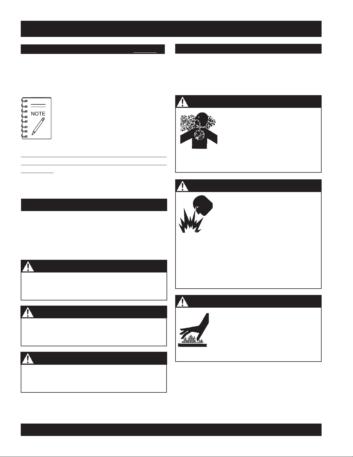
WARNING - LETHAL EXHAUST GASES
WARNING - EXPLOSIVE FUEL
is running or hot.
DO NOT overfill tank, since spilled fuel could ignite if it
comes into contact with hot engine parts or sparks from
the ignition system. Store fuel in approved containers,
in well-ventilated areas and away from sparks and
flames. NEVER use fuel as a cleaning agent.
Diesel engine exhaust gases contain
poisonous carbon monoxide. This gas
is colorless and odorless, and can
cause death if inhaled. NEVER
operate this equipment in a confined
area or enclosed structure that does
not provide ample free flow air.
Diesel fuel
its vapors can cause an explosion if
ignited. DO NOT start the engine near
spilled fuel or combustible fluids. DO
NOT fill the fuel tank while the engine
is extremely flammable, and
WARNING
You COULD be KILLED or SERIOUSLY injured if
you do not follow directions.
CAUTION
You CAN be injured if you do not follow directions
PAGE 6 — MAYCO LS400/LS500 PUMP — OPERATION AND PARTS MANUAL — REV. #6 (09/19/11)
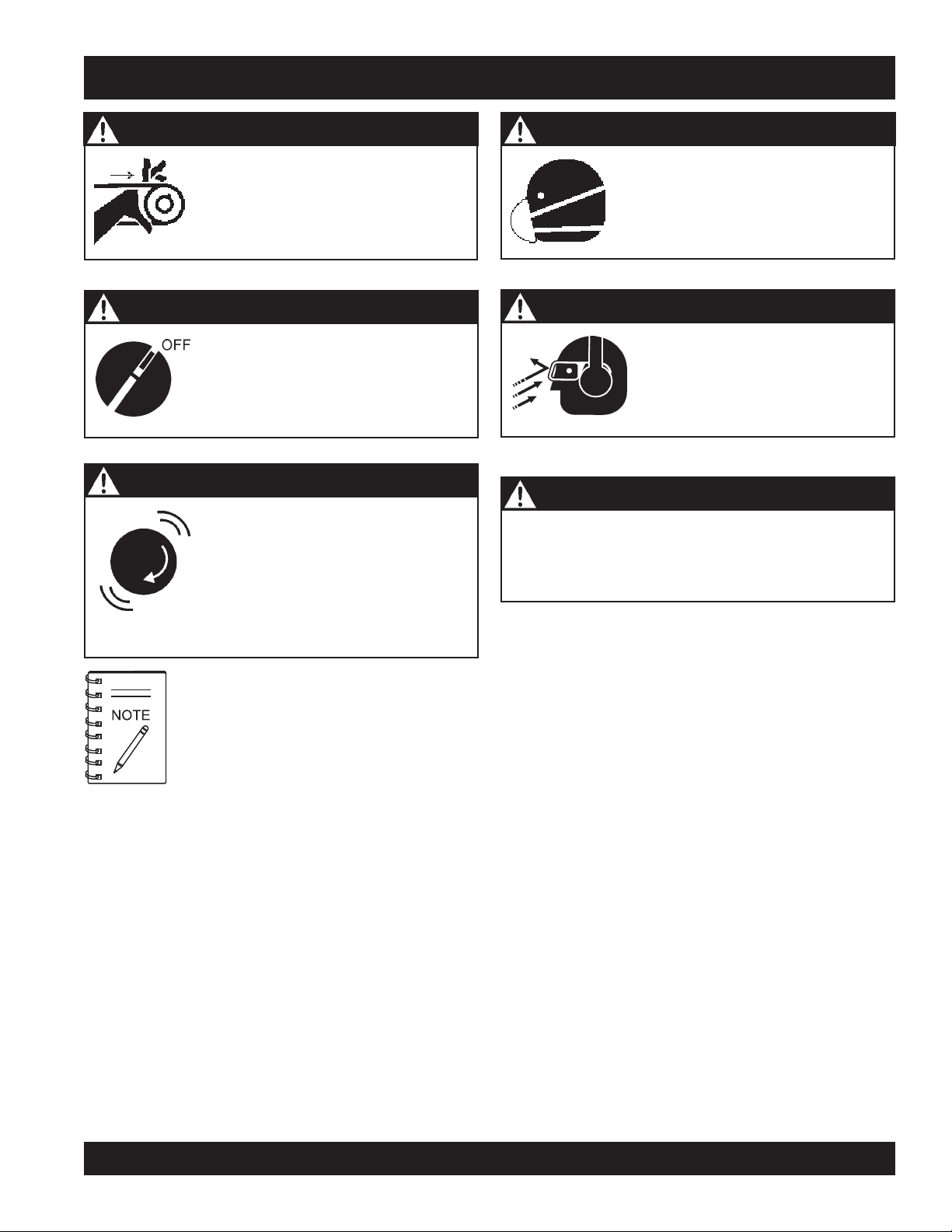
WARNING - BURN HAZARDS
Engine components can generate
extreme heat. To prevent burns, DO NOT
touch these areas while the engine is
running or immediately after operations.
NEVER operate the engine with heat
shields or heat guards removed.
LS400/LS500 PUMP — SAFETY MESSAGE ALERT SYMBOLS
WARNING - ROTATING PARTS
NEVER operate equipment with covers,
or guards removed. Keep
hands, hair
moving parts to prevent injury.
CAUTION - ACCIDENTAL STARTING
ALWAYS place the Engine ON/OFF
switch in the OFF position. NEVER
perform maintenance on the unit with
the ignition key in the ON position.
CAUTION - OVER-SPEED CONDITIONS
NEVER tamper with the factory
settings of the engine governor or
settings. Personal injury and damage
to the engine or equipment can result
if operating in speed ranges above
maximum allowable.
and clothing away from all
fingers
CAUTION - RESPIRATORY HAZARDS
,
CAUTION - SIGHT AND HEARING HAZARDS
CAUTION - EQUIPMENT DAMAGE MESSAGES
Other important messages are provided throughout
this manual to help prevent damage to your concrete
pump, other property, or the surrounding environment.
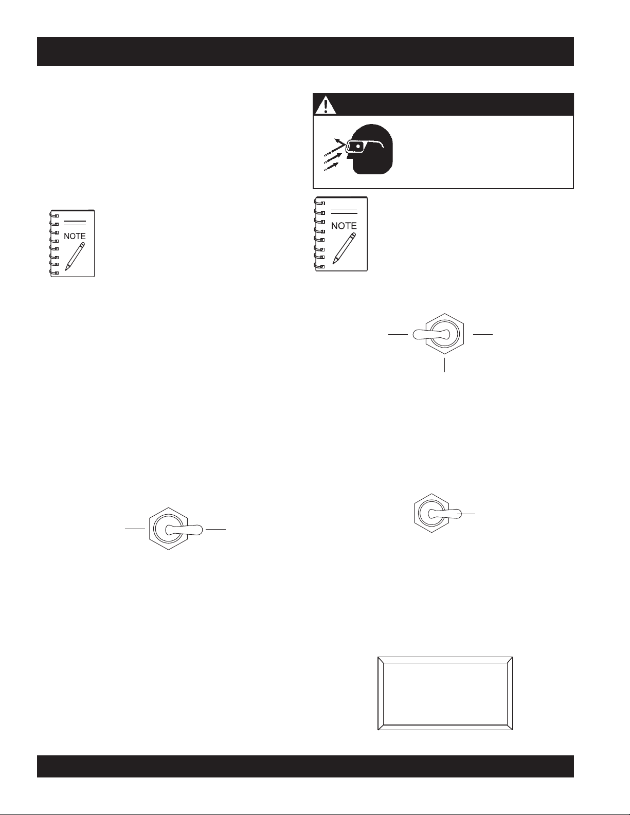
ALWAYS wear approved
protection.
This machine is capable of
producing noise levels above 85 dB.
Hearing protection is required.
Always wear eye protection.
respiratory
This
pump
, other property, or the
surrounding environment could be damaged
if you do not follow instructions.
MAYCO LS400/LS500 PUMP — OPERATION AND PARTS MANUAL — REV. #6 (09/19/11) — PAGE 7
LS400/LS500 PUMP — RULES FOR SAFE OPERATION
■
DANGER - READ OPERATION AND PARTS
Failure to follow instructions in this manual may lead to
death!
serious injury or even
operated by trained and qualified personnel only! This
equipment is for industrial use only.
The following safety guidelines should always be used when
operating the LS400/LS500 concrete pump:
GENERAL SAFETY
■
DO NOT operate or service this
equipment before reading this entire
manual.
■
This equipment should not be
operated by persons under 18 years
of age.
■
NEVER operate this equipment without proper protective
clothing, shatterproof glasses, steel-toed boots and other
protective devices required by the job.
This equipment is to be
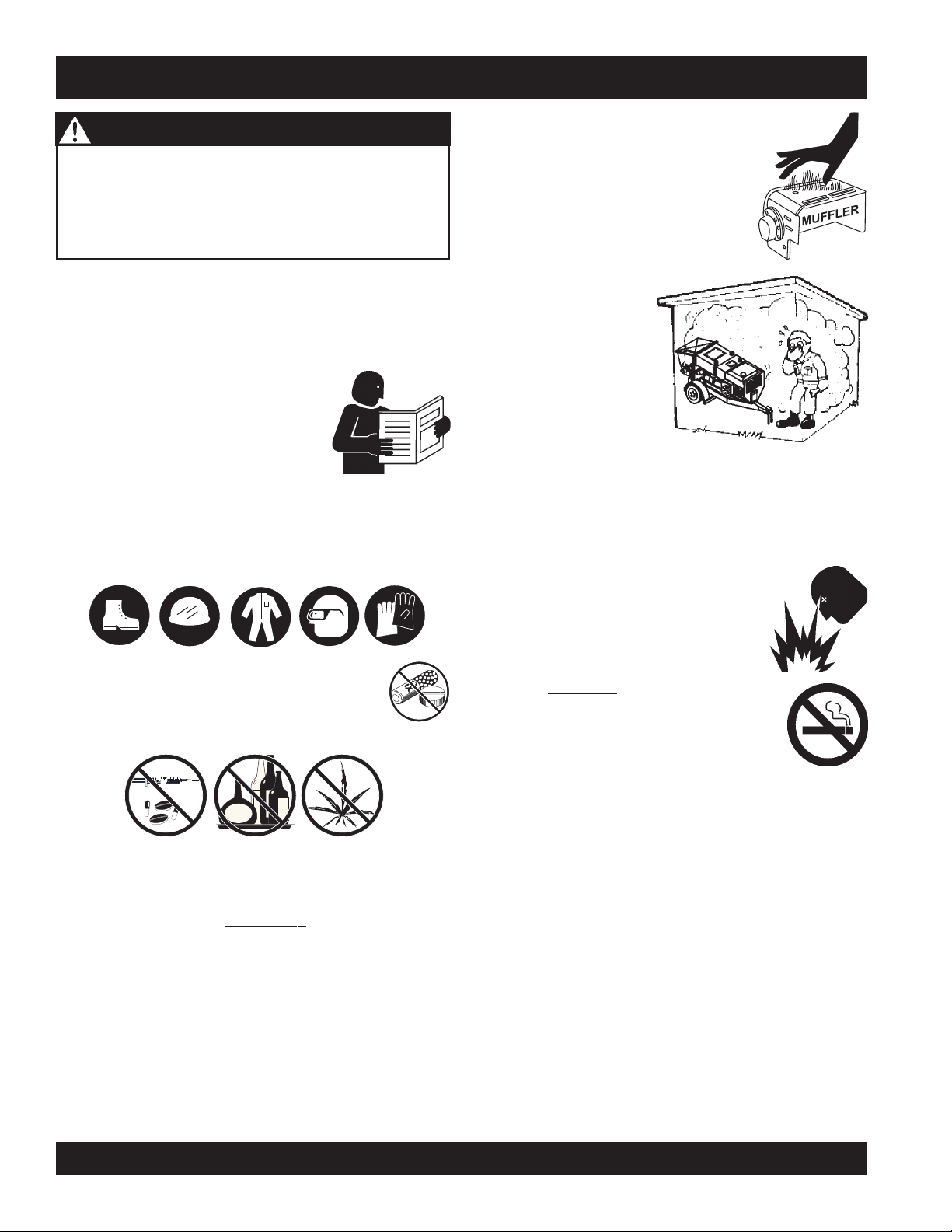
NEVER touch the hot exhaust manifold, muffler
or cylinder. Allow these parts to cool before
servicing engine or pump.
■
High Temperatures – Allow the engine
to cool before adding fuel or performing
service and maintenance functions.
Contact with
cause serious burns.
■
The engine section of this
pump requires an
adequate free flow of
cooling air.
operate the pump in any
enclosed or narrow area
where free flow of the air
is restricted. If the air flow is restricted it will cause serious
damage to the pump or engine and may cause injury to
people. Remember the pump's engine gives off
carbon monoxide gas.
■
ALWAYS refuel in a well-ventilated area, away from sparks
and open flames.
hot!
components can
NEVER
DEADLY
■
■
NEVER operate this equipment when not feeling
well due to fatigue, illness or taking medicine.
■
NEVER operate this equipment under the
influence or drugs or alcohol.
■
ALWAYS check the machine for loosened threads or bolts
before starting.
■
ALWAYS wear proper respiratory (mask),
eye
protection equipment when operating the pump.
■
Whenever necessary, replace nameplate, operation and
safety decals when they become difficult read.
■
Manufacture does not assume responsibility for any
accident due to equipment modifications.
■
NEVER use accessories or attachments, which are not
recommended by Multiquip for this equipment. Damage
to the equipment and/or injury to user may result.
hearing
and
■
■
■
■
■
■
■
ALWAYS use extreme caution when
working with flammable liquids. When
refueling, stop the engine and allow it to
cool.
NEVER
machine. Fire or explosion could result from
fuel vapors
engine.
NEVER operate the pump in an explosive atmosphere or
near combustible materials. An explosion or fire could
result causing severe
Topping-off to filler port is dangerous, as it tends to spill
fuel.
ALWAYS remove the
unattended.
ALWAYS block the
slope.
ALWAYS maintain this equipment in a safe operating
condition at all times.
ALWAYS stop the engine before servicing, adding fuel or
oil.
smoke
around or near the
, or if fuel is spilled on a
bodily harm or even death.
ignition key
wheels
when leaving the pump
on the unit when using on a
hot!
PAGE 8 — MAYCO LS400/LS500 PUMP — OPERATION AND PARTS MANUAL — REV. #6 (09/19/11)

LS400/LS500 PUMP — RULES FOR SAFE OPERATION
■
NEVER run engine without air filter. Severe engine
damage may occur.
■
ALWAYS be sure the operator is familiar with proper safety
precautions and operation techniques before using pump.
■
ALWAYS store equipment properly when it is not being
used. Equipment should be stored in a clean, dry location
out of the reach of children.
■
DO NOT operate this equipment unless the hopper grate,
guards and safety devices are attached and in place.
■
CAUTION must be exercised while servicing this
equipment. Rotating and moving parts can cause injury
if contacted.
■
Keep all
from the equipment at all times.
■
Before start-up, check the hopper and remove all foreign
matter and debris.
■
DO NOT use worn or damaged hose couplings, inspect
all hoses and couplings for wear. Replace any worn or
defective hose or couplings immediately.
■
Keep hands out of the hopper when the engine is running.
■
DO NOT disconnect hose couplings or nozzle while under
pressure. Relieve pressure by activating the reverse
function switch located on the control panel.
■
Unauthorized equipment modifications will void all
warranties.
inexperienced
and
unauthorized
people away
TRANSPORTING
■
■
■
Towing
■
■
■
■
■
■
■
■
■
ALWAYS shutdown engine before transporting the pump.
Tighten fuel tank cap securely to prevent fuel from
spilling.
Drain fuel when transporting pump over long distances
or bad roads.
Before towing, check the hitch and secure the safety
chain to the towing vehicle.
When towing, an adequate safety chain must be fastened
to the frame, refer to Towing Guidelines.
Tow only with a vehicle and hitch rated to pull a 6,000
lbs. load.
If unit is equipped with ball hitch coupler, use only 2" all
steel ball rated for minimum of 6,000 lbs. Use 1" hardened
steel pull pin, if not equipped with ball hitch.
This equipment shall not be towed or operated by
individuals who cannot read understand the signs, decals
or operating instructions.
When towing at night,
DO NOT tow unit with hopper full of material.
DO NOT tow unit with hoses attached.
DO NOT tow unit in excess of 55 MPH on highways.
always
have rear tail lights ON.
■
Check all fasteners periodically for tightness. Also check
towing tongue bolt, lock nut and wheel lug nuts for wear.
■
Test the
test is to shut down the engine.
■
Refer to the
technical questions or information recommended by
Multiquip for this equipment. Damage to the equipment
and or injury to user may result.
■
Always use properly rated hoses and clamps — 1500
PSI and higher.
pump's ON/OFF
DEUTZ Engine Owner's Manual
MAYCO LS400/LS500 PUMP — OPERATION AND PARTS MANUAL — REV. #6 (09/19/11) — PAGE 9
switch. The purpose of this
for engine
LS400/LS500 PUMP — RULES FOR SAFE OPERATION
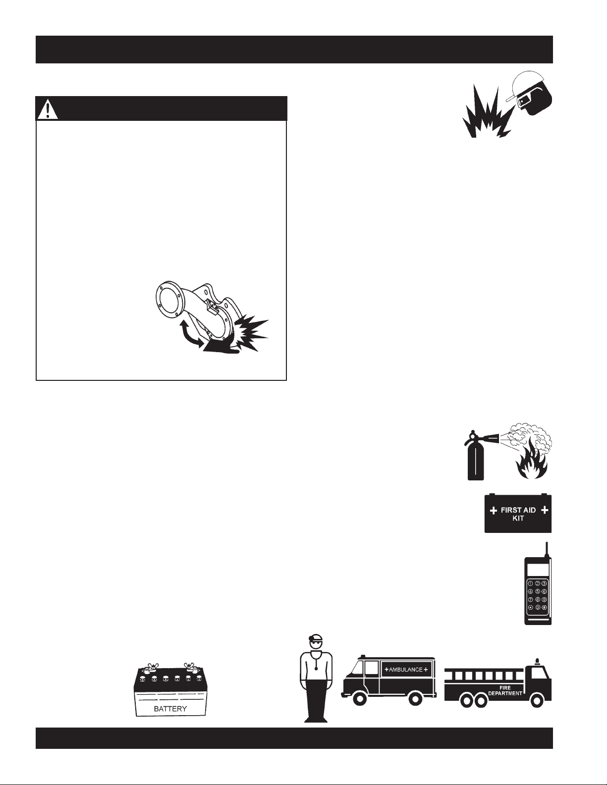
MAINTENANCE SAFETY
DANGER - AMPUTATION RISK
During routine maintenance or removing material
blockage, you will be required to put your hand in the
concrete cylinders or near the shuttle tube. You are at
EXTREME RISK
engine is running or if pressure is in the hydraulic
system.
Prior to performing any maintenance on the pump,
follow described lock out-tag out procedures. Stop the
engine by turning off the ignition switch and remove
the starter key. Place a “DO NOT OPERATE” tag
over the switch and disconnect the battery. The
pressure reading on the
accumulator pressure
gauge
ZERO. ALWAYS make
sure the accumulator
circuit pressure reads
zero prior to performing any maintenance on the pump.
■
NEVER lubricate components or attempt service on a
running pump .
MUST
of injury or
read
AMPUTATION
if the
■■
■
DO NOT drop the battery. There
■■
is the possibility of risk that the
battery may explode.
■■
■
DO NOT expose the battery to
■■
open flames, sparks, cigarettes
etc. The battery contains combustible gases and liquids.
If these gases and liquids come in contact with a flame
or spark, an explosion could occur.
■■
■
ALWAYS keep the battery charged. If the battery is not
■■
charged a buildup of combustible gas will occur.
■■
■
ALWAYS keep battery charging and cables in good
■■
working condition. Repair or replace all worn cables.
■■
■
ALWAYS recharge the battery in an vented air
■■
environment, to avoid risk of a dangerous concentration
of combustible gases.
■■
■
In case the battery liquid (dilute sulfuric acid) comes in
■■
contact with
immediately with plenty of water.
■■
■
In case the battery liquid (dilute sulfuric acid) comes in
■■
contact with your eyes, rinse eyes immediately with
plenty of water, then contact the nearest doctor or hospital,
and seek medical attention.
EMERGENCIES
clothing or skin
, rinse skin or clothing
■
ALWAYS allow the pump a proper amount of time to
cool before servicing.
■
Keep the pump in proper running condition.
■
Fix damage to the pump immediately and always replace
broken parts.
■
Dispose of hazardous waste properly. Examples of
potentially hazardous waste are used motor oil, fuel and
fuel filters.
■
DO NOT use plastic containers to dispose of hazardous
waste.
BATTERY
The battery contains acids that can cause injury to the eyes
and skin. To avoid eye irritation,
Use well insulated gloves when picking up the battery. Use
the following guidelines when handling the battery:
always
wear safety glasses.
■
ALWAYS know the location of the
nearest
■
ALWAYS know the location of the
nearest and
■
In emergencies
nearest phone or
Also know the phone numbers of the nearest
ambulance, doctor
information will be invaluable in the case of an
emergency.
fire extinguisher
first aid kit
always
.
.
know the location of the
keep a phone on the job site
and
fire department
.
. This
PAGE 10 — MAYCO LS400/LS500 PUMP — OPERATION AND PARTS MANUAL — REV. #6 (09/19/11)

NOTES
MAYCO LS400/LS500 PUMP — OPERATION AND PARTS MANUAL — REV. #6 (09/19/11) — PAGE 11
LS400/LS500 PUMP — SPECIFICATIONS
SNOITACIFICEPSPMUP.1ELBAT
ledoM004-SL005-SL
etaRgnipmuP
dohteMgnipmuPnotsiPgnitacorpiceR
eziSetagerggAmumixaM )mm83(sunim.ni2/1-1
thgieHgnipmuPlacitreV )m67(.tf052fossecxEotpU
erusserPecaFnotsiPisp
ecnatsiDgnipmuPlatnoziroH *)m503(.tf0001
yticapaCxoBnoitacirbuLrednilyC )sretiL6.7(snollaG2
iulFciluardyH )sretiL981(snollaG05
SeriT )mm653xmm781(.ni41x.ni53.7
yticapaCd
yticapaCknaTleuF )sretiL67(snollaG04
yticapaCreppoH reximerver/dwflanoi
esoHlairetaM
ledoMenignE
)sdiulfhtiw(thgieW )gk951,2(.sbl067,4
)gnippihs/yrd(thgieW )gk860,2(.sbl065,4
ezi
leseiDztueD
1102L4F
.uc04otpU
*ruohrep.sdy
0511
tpohtiw.tf.uc01
.aid.ni5,.ni4,.ni3
.uc05otpU
*ruohrep.sdy
)mm721,mm6.101,mm2.67(
obruTztueD
1102L4FBleseiD
snoitpO
dyH
rezilibatSraeRciluar
,rotarbiVneercSreppoH,lortnoCetomeRsseleriW
snotitidnocetisbojdnadesuezisenil,pmuls,ngisedximnognidnepedyravlliwtuptuoemuloV*
.2ELBATSNOITACIFICEPSENIGNE
ledoM
epyT
srednilyCfo.oN
ortSxeroB
ek
tuptuOdetaR
tnemecalpsiD
atS
gnitr
yticapaCliOebuL
epyTleuF
F1102L4FztueD
enignEleseiD
leseiDdelooc-riA,ekorts4
4
.ni5x.ni91.4
)mm721xmm601(
mpr0003@PH06mpr0003@PH97
)L37.2(.ni.uc761
CDV21cirtcelE
)sretil5.2(.lag5.9
leuFleseiD2#
F1102L4FBztueD
enignEleseiD
yrettaB
72puorGVCDV21
PAGE 12 — MAYCO LS400/LS500 PUMP — OPERATION AND PARTS MANUAL — REV. #6 (09/19/11)
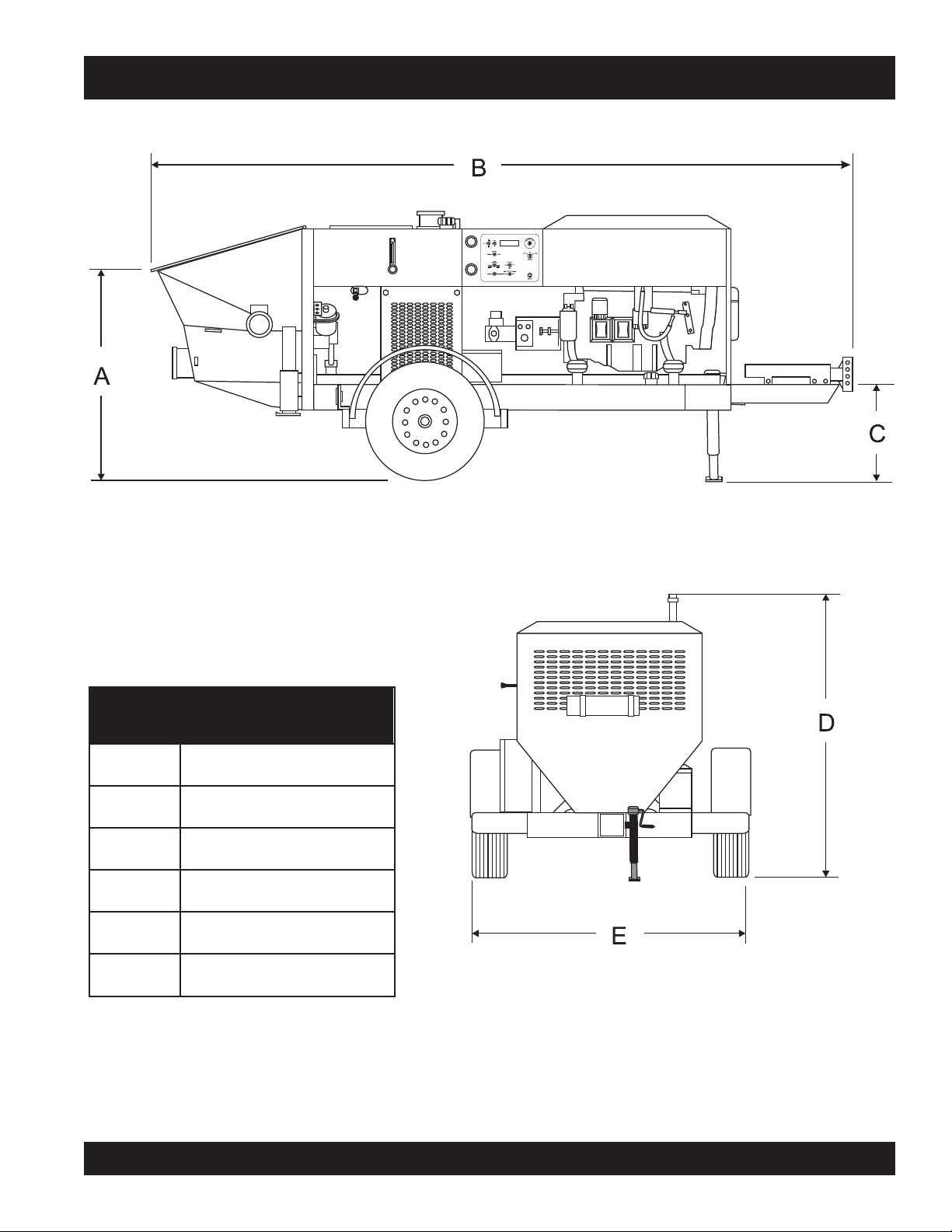
LS400/LS500 PUMP — DIMENSIONS
SNOISNEMID.3ELBAT
.FERSNOISNEMID
A).mc2.901(.ni34
B).mc734(.ni271
C).mc16(.ni42
D).mc8.771(.ni07
E).mc2.271(.ni86
Figure 1. Dimensions
MAYCO LS400/LS500 PUMP — OPERATION AND PARTS MANUAL — REV. #6 (09/19/11) — PAGE 13
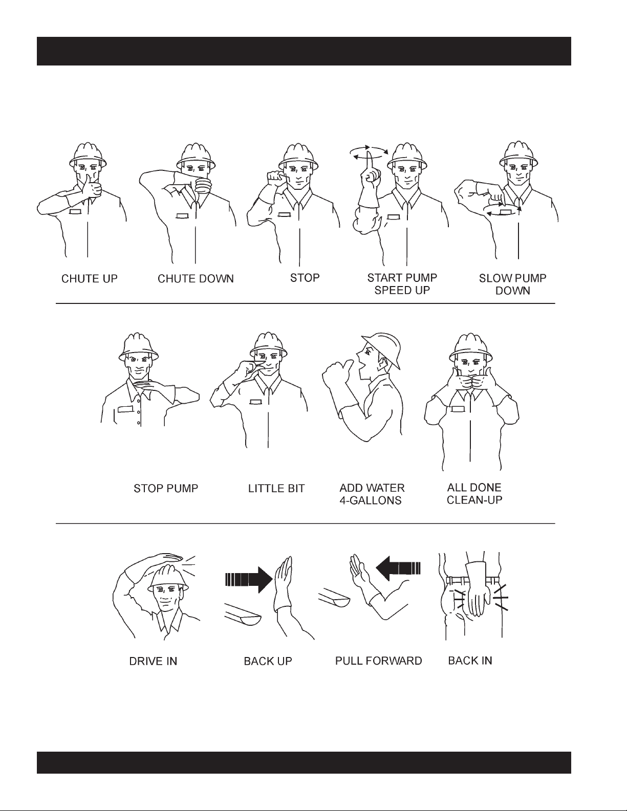
LS400/LS500 PUMP — IMPORTANT HAND SIGNALS
Figure 2 displays the basic hand signals commonly used in concrete pumping operations.
Figure 2. Operation Hand Signals
PAGE 14 — MAYCO LS400/LS500 PUMP — OPERATION AND PARTS MANUAL — REV. #6 (09/19/11)

LS400/LS500 PUMP — GENERAL INFORMATION
CONCRETE MIX DESIGN
Mix design is most important to achieve maximum pumpability.
Pumpability is affected by, among other factors, the type and
gradation of aggregate used. Natural aggregates make a more
workable mix and pump more readily than crushed aggregates.
A blend of natural and crushed aggregates will produce a
workable mix. The type and gradation of aggregates is equally
important for workability as the size and percentage of coarse
aggregates in the mix.
The term “aggregates” describes all of the solid materials, from
the largest rock to the smallest grain of sand, contained in the
concrete mix.
Concrete mixes with a consistency as dry as one-inch slump
and as wet as ten-inch slump have been pumped; but for
maximum efficiency from the pump, a slump ranging from two to
six inches will produce a more workable mix than one that
contains more or less water.
The principle of concrete pumping is based on self-lubrication.
As it moves through the transfer line, the concrete takes the
shape of a plastic cylinder. It is forced through the transfer line on
a film of mortar that is self-troweled to the service of the transfer
line around its full periphery by the slug of concrete itself.
A slump rating should be used with discretion; it is not always a
real indication of the pumpability of the mix. The concrete may
be workable in the sense that it will readily flow into place, but
the same mix may not respond to pressure. Overly wet mixes
tend to separate. In addition to affecting the strength and quality
of the concrete, the delivery system will not tolerate separation.
Overly dry mixes are similarly unsatisfactory if they lack plasticity
and tend to be crumbly. To be properly pumped, the mix must be
able to continuously coat the inside of the line with a lubricating
seal of mortar.
There are four ways in which this seal can be lost:
1. By pumping excessively wet mixes which do not have
enough cohesion to hold together.
2. By pumping harsh undersanded concrete with poorly graded
aggregates which can jam together when the pressure
becomes too great for the insufficient amount of sand to
hold the aggregates apart.
3. By getting a rock pocket, such as mixer tailings, into the
pump valve. This rock pocket will have an insufficient coating
of mortar and the mix will not be plastic enough to allow the
valve to operate or the mix to move in the line.
4. Through excessive bleeding. If the mix is short or fines, but
the sand is otherwise fairly well graded, bleeding will not
normally create any problems as long as the pump continues
operation. But, if the pump is shut down, bleeding can result
in a loss of lubrication and blocked erratic flow.
The above are bad concrete practices, regardless of how the
mix is to be placed. But, these points do show that special mixes
are not always needed, within limits, for pumping concrete. Good
aggregate gradation is most important to pump concrete the
maximum distance.
The use of admixtures can have a beneficial effect on pumpability.
Most of the dispersing agents will fatten, retard bleeding, and
increase workability. Thus, the average concrete can be pumped
for appreciably longer distances. Air entraining agents will also
improve workability, although they cannot be used as a substitute
for good gradation of the aggregate. Pumping will not appreciably
affect the final air content of the mix. High-early cement tends to
give a more readily pumpable mix with superior water retaining
qualities. However, if delays are likely to occur, extra care must
be exercised due to the faster setting time over regular cement.
The Mayco LS400/LS500 models will pump a wide variety of
concrete pump mixes. But, there are guidelines that must be
followed. Use this information in conjunction with the
section of this manual.
Operation
MAYCO LS400/LS500 PUMP — OPERATION AND PARTS MANUAL — REV. #6 (09/19/11) — PAGE 15

LS400/LS500 PUMP — GENERAL INFORMATION
REGIONAL DIFFERENCES
Concrete is made by mixing locally available rock and sand with
cement and water. For this reason there are great differences in
the pumpability of concrete from one region of the country to
another.
It is impossible to define a specific mix for each region that the
concrete pump be will working in. Therefore, the mixes listed in
Appendix - Concrete Mix Information will provide a basic
guideline for establishing the proper mix design for your area.
Use this information to specify your requirements to your local
ready-mix batch plant, contractor and civil engineer. It may take
minor adjustments to make a mix pumpable, so you should
explain your needs.
The elements that have to be controlled and consistently
maintained by the batch plant are:
1. The sizing and mix percentage of rocks, gap graded from
the largest down through the smallest sizes.
2. Sand with a sieve analysis that has the proper percentage
of fines, ASTM C33 spec.
3. Sufficient cement to produce the required design strength
of the concrete and provide the lubricating binder to pump
the concrete through the delivery system.
5. The proper amount of water to make a workable slump and
plasticize the mix.
In addition, this Mayco Concrete Pump can be used to pump a
large aggregate hard rock as follows:
1. Pea rock (1/2" minus) pump with mixes being as low as 30%
rock and 70% sand. (See page 44, for comments on cleaning
the pump.)
2. Shortening pea rock when used with an air compressor
and nozzle. (See back pages for recommended setup.)
3. “Mud Jacking”, high pressure grouting.
Use a minimum of:
500 lbs. of cement/cu yd for 2500 p.s.i. concrete after 28
days.
530 lbs. of cement/cu yd for 3000 p.s.i. concrete after 28
days.
600 lbs. of cement/cu yd for 4000 p.s.i. concrete after 28
days.
4. Admixture pump-aid if necessary.
PAGE 16 — MAYCO LS400/LS500 PUMP — OPERATION AND PARTS MANUAL — REV. #6 (09/19/11)
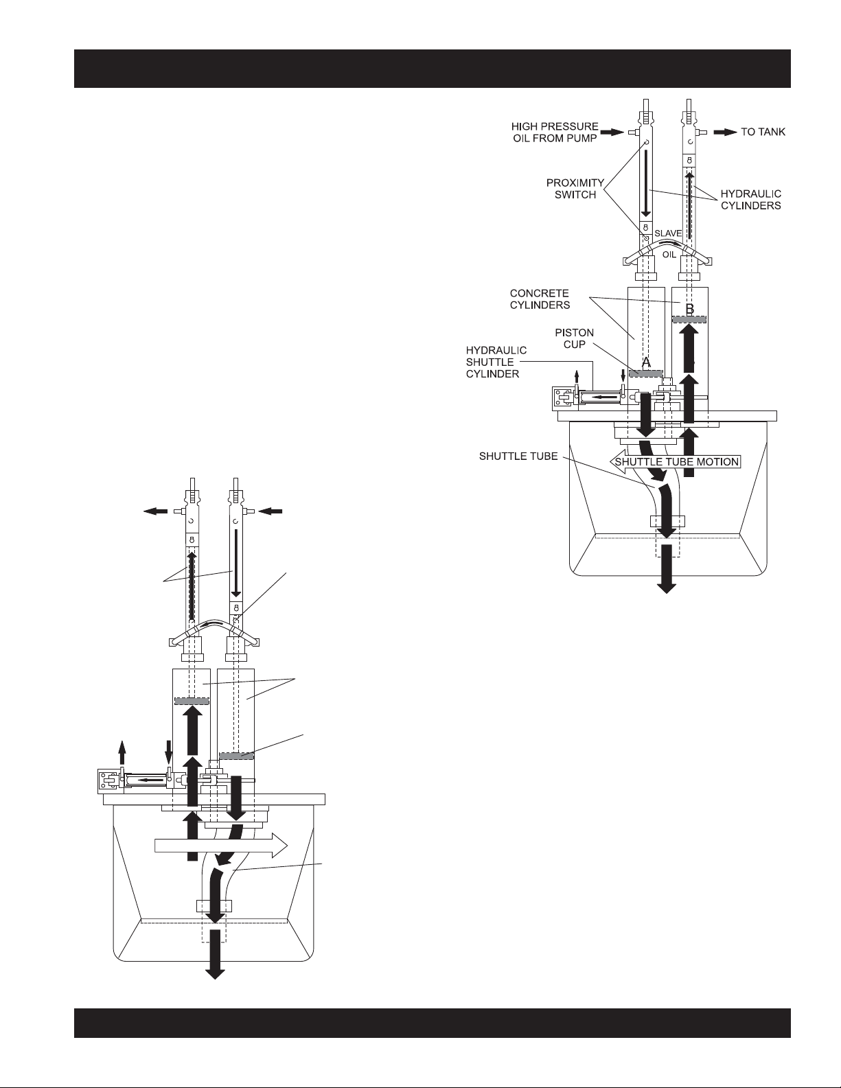
LS400/LS500 PUMP — HOW IT WORKS
The following is a brief explanation of how the concrete cylinders,
hydraulic cylinders, shuttle tube, valves and hopper work in
sequence to pump concrete.
The hydraulic pressure is generated by a variable volume,
pressure compensated, axial piston pump that is driven by a
diesel engine. The rod sides of the drive cylinders are
hydraulically connected together creating a “slave circuit,” which
allows hydraulic oil to transfer from one piston to the other.
The two part cycling sequence is initiated by an electrical signal
generated by two proximity switches activated by the drive
cylinder. The proximity switches are normally open, magnetically
sensing the movement of the main drive cylinder. As the drive
cylinder piston head passes the proximity switch, an electrical
signal is sent to the solenoid operated pilot valve which in turn
directs pilot oil to the four valves controlling the drive cylinder
and the shuttle cylinder.
A one-gallon accumulator assists the movement of the shuttle
tube. This circuit assures that the shuttle tube will throw with the
same intensity of each stroke regardless of how fast the main
drive cylinders are cycling.
TO TANK
HYDRAULIC
CYLINDERS
SLAVE
OIL
A
B
SHUTTLE TUBE MOTION
HIGH PRESSURE
OIL FROM PUMP
PROXIMITY
SWITCH
CONCRETE
CYLINDERS
PISTON
CUP
SHUTTLE TUBE
Figure 4. Pumping Cycle 2
In the first cycle, hydraulic pressure is applied to cylinder (B),
causing the hydraulic piston, which is connected to the concrete
piston and piston cup, to discharge concrete into the delivery
line (Figure 3).
As one cylinder is discharging concrete, the hydraulic oil from
the rod side (B) of the drive cylinders is being transferred through
the slave circuit causing the opposite cylinder (A) to move back
on the suction stroke, filling the cylinder with concrete.
The shuttle tube is sequenced to pivot to each concrete cylinder
as the drive cylinders stroke to push concrete. As the second
cycling sequence begins (Figure 4), the shuttle tube pivots to
the opposite cylinder (A). The hydraulic piston passes under the
proximity switch and sends pressure to the piston, causing it to
stroke and discharge concrete into the delivery line. Hydraulic
oil is transferred through the slave circuit to cylinder B, causing it
to start a suction stroke, refilling it with concrete. The pumping
sequence then repeats for the duration of the operation.
Figure 3. Pumping Cycle 1
MAYCO LS400/LS500 PUMP — OPERATION AND PARTS MANUAL — REV. #6 (09/19/11) — PAGE 17
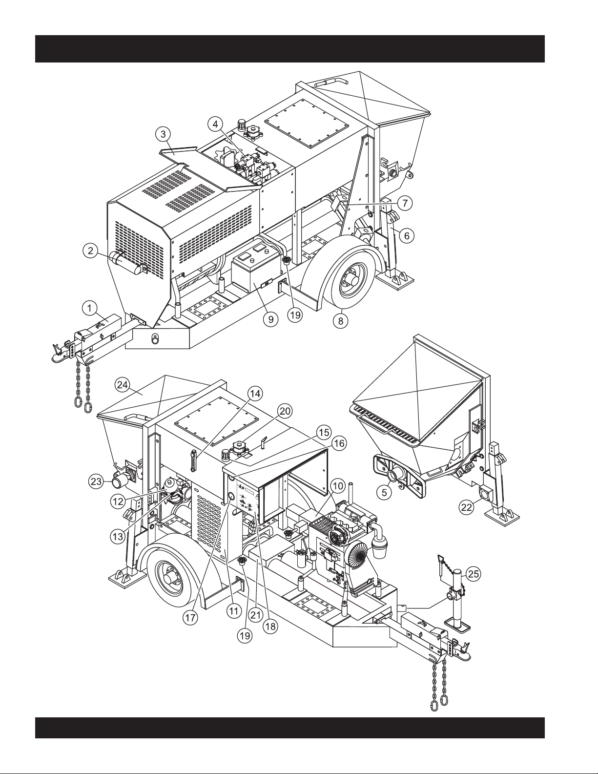
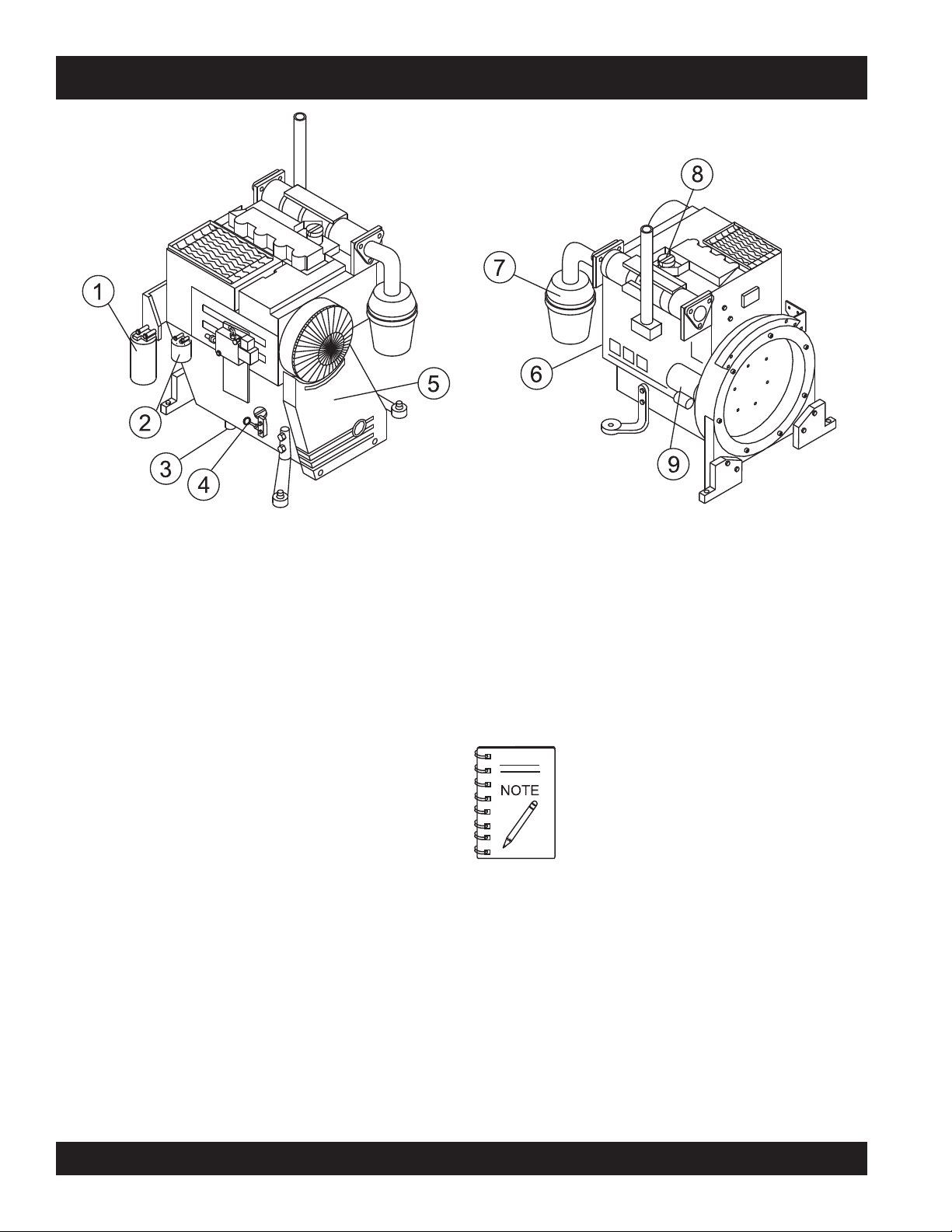
LS400/LS500 PUMP — PUMP COMPONENTS
Figure 5. Major Pump Components
PAGE 18 — MAYCO LS400/LS500 PUMP — OPERATION AND PARTS MANUAL — REV. #6 (09/19/11)

LS400/LS500 PUMP — PUMP COMPONENTS
Figure 5 illustrates the location of the major components for
the LS400/LS500 Concrete Pump. The function of each
component is described below:
1. Tow Hitch Coupler – Requires a 2-inch ball hitch or a
3-inch pintle. Capable of towing 6,000 lbs.
2. Documentation Box – Contains engine and pump
operation, parts and maintenance information.
3. Manifold Access Door– Release latch and lift door to
access the Hydraulic Manifold Block.
4. Hydraulic Manifold Block – Manifold block that
controls the flow of hydraulic pressure to the
components required to control the pump.
5. Hopper Discharge Sleeve – Connect hoses or steel
pipes to the discharge sleeve for pouring concrete.
6. Pump End Jack Stand – Use this jack stand to level
and support the rear end of the pump. NEVER deploy
on un-level ground and always check for firmness of
ground.
7. Shuttle Cylinder – Under pressure, the shuttle cylinder
shears concrete passing from the concrete cylinder to
the delivery line during the cycle phase.
8. Tires — This trailer uses two ST205-750 x15E type
tires. Tire inflation pressure is the most important factor
in tire life. Pressure should be checked to
before operation. DO NOT bleed air from tires when
they are hot. Check inflation pressure weekly during
use to insure the maximum tire life and tread wear.
50 psi cold
15. Hydraulic Oil Tank/Cap– Remove cap to add hydraulic
fluid. Fill with Shell Oil Tellus 68 or Mobil Oil DFE26 if
level is low.
16. Accumulator Pressure Gauge– Used to monitor
accumulator pressure. Pressure should read at least
1750 psi for correct pump operation.
17. Pumping Pressure Gauge – Used to monitor pressure
in the concrete cylinders and shuttle tube.
18. Control Box – Contains the electrical components
required to run the pump. See Control Box Components
section for component callouts.
19. Fuel Tank/Cap – Fill with diesel fuel. Fuel tank (cell)
holds approximately 40 gallons (176 liters). DO NOT
top off fuel. Wipe up any spilled fuel immediately.
20. Hydraulic Oil Filter – This in-tank return hydraulic
filter with a 10 micron cleanable filter is designed to
remove all particles large enough to cause wear and
job break down. Under normal conditions, replace every
6 months.
21 Lubrication Box – This box is empty when shipped
from the factory. Please fill with 3 gallons (11.35 liters)
of SAE 30 motor oil for first time use. Also check the
dual clean-out point on bottom of lubrication box for a
secure tight fit.
22. Rear Running Lights – ALWAYS check and make
sure both the right and left running lights are functioning
correctly before towing the pump.
9. Battery – This unit uses a +12 VDC type battery.
ALWAYS use gloves and eye protection when handling
the battery.
10. Hydraulic Pump – This unit incorporates an axial
variable displacement hydraulic piston pump.
11. Heat Exchanger – Reduces temperature of the
hydraulic oil. The exchanger draws oil from the hydraulic
tank through a filter and into the heat exchanger before
allowing it to flow into the hydraulic system.
12. Accumulator – Stores hydraulic oil under pressure and
releases it to the shuttle cylinder and provides the
pressure needed to ensure enough force is provided
during cycle.
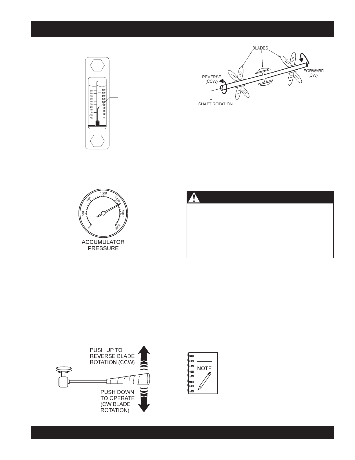
13. Remixer Control Lever – Controls the forward/reverse
motion of the hopper remixer paddles.
14. Hydraulic Oil Sight Glass – Use to determine the
amount of hydraulic oil remaining in tank. The sight
glass also contains a temperature gauge for monitoring
the temperature of the hydraulic oil.
MAYCO LS400/LS500 PUMP — OPERATION AND PARTS MANUAL — REV. #6 (09/19/11) — PAGE 19
23. Remixer Motor – Drives the remixer paddles inside
24. Hopper/Hood – Lift hood to fill. Concrete from a Redi-
25. Tow End Jack Stand – Use this jack stand to level
the hopper. The motor direction is controlled by the
remixer control lever.
Mix truck is poured into this hopper. The hopper can
hold 10 cu. ft of concrete with optional forward/reverse
mixer. NEVER put hands or any other parts of you body
into the hopper.
and support the tow end of the pump.
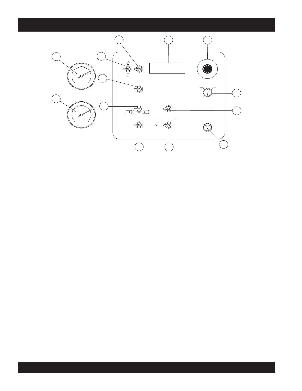
LS400/LS500 PUMP — DIGITAL CONTROL PANEL COMPONENTS
5
12
13
0
0
0
1
0
5
7
0
0
5
0
ACCUMULATOR
PRESSURE
0
0
0
1
0
5
7
0
0
5
0
PUMPING
PRESSURE
4
DECREASE
FORWARD
AUTOMATIC
RESET
SET
VOLUME
FLOW
DIRECTION
INCREASE
REVERSE
JOG
1
2
5
0
1
5
0
0
11
2
0
0
0
1
2
5
0
1
5
0
0
2
0
0
0
SCROLL
7
9
Figure 6. Pump Digital Control Panel Components
1. Emergency Stop Button – Press emergency stop
9. Cylinder Stroke Control Switch – This 2-position
button to stop pump in an emergency. Turn knob
counterclockwise to disengage the stop button.
2. Ignition Switch – Insert the ignition key here to start
the engine. Turn the key clockwise to the ON position,
then continue turning clockwise to the START position
and release. To stop the engine turn the key fully
counterclockwise to the STOP position.
3. Digital Readout Screen – Displays and monitors the
various functions of the machine.
10. Manual Cylinder Jogging Switch – This 2-position
4. Scroll Switch – Allows the operator to scroll the various
readout screens.
5. Reset Switch – Allows the operator to reset the stroke
counter.
6. Remote Cable Connector – Insert the remote control
input cable into this connector.
7. Direction Control Switch – This 2-position switch
11. Stroke Volume Control Switch – Increases or
controls the direction of flow for any mix in the pump.
The
leftmost
forward and the
position sets the pumping direction to
rightmost
position sets the pumping
12. Accumulator Pressure Gauge – This gauge monitors
direction to reverse.
8. Pumping Control Switch – This 3-position switch
controls the pumping of the pump. The
position (REMOTE) is for use with the remote control
unit, the
pumping operation, and the
leftmost
position (LOCAL) is for normal
centermost
rightmost
13. Main Pressure Gauge – This gauge monitors the
position
(CENTER OFF) prevents pumping.
3
1
C
N
Y
E
G
S
R
T
O
E
P
M
E
ON
OFF
START
2
CONTROL
REMOTE
LOCAL
CENTER
OFF
CYLINDER STROKE
JOG “B”
JOG “A”
10
switch controls the pumping function. The
position (AUTOMATIC) sets the pump to
cycling
. Set the switch to this position for normal pump
IGNITION
8
REMOTE
6
leftmost
automatic
operation.
The
rightmost
automatic to
to be manually cycled using the
Jogging Switch
position (JOG) changes the pump from
manual cycling
. This allows the cylinders
Manual Cylinder
.
switch allows the operator to manually jog the cylinders
to assist in clearing material line packs and is used to
test pumping pressure (See
Initial Start-up Procedure
section of this manual for testing procedure).
The
leftmost
rightmost
position jogs Cylinder “A” and the
position jogs Cylinder “B”.
decreases the number of strokes per minute of the
pump.
the internal pressure of the Accumulator tank. Normal
internal pressure should read approximately 1750 PSI
during pumping.
system pressure while pumping material. The maximum
pressure rating is 4400 PSI ± 50.
PAGE 20 — MAYCO LS400/LS500 PUMP — OPERATION AND PARTS MANUAL — REV. #6 (09/19/11)
LS400/LS500 PUMP — DIGITAL READOUT SCREEN
PRIMARY SCREEN
Screen 5
Displays the ON/OFF electrical signal status of the various
Screen 1
Indicates the various modes of the switch settings.
Monitors engine RPM - Idle speed 900, High speed 2550.
Battery charge indicator - Normal charge 13+ volts.
12 volt solenoids (Swing A circuit, Main A circuit, Main B
circuit).
INDICATES
SWING A
CIRCUIT IS OFF
Indicates electrical malfunction - Refer to Troubleshooting
section.
INDICATES
STATUS OF PUMP
( ON OR OFF)
INDICATES
BATTERY
CHARGE
LS 400 OFF
0000 ENG RPM
BATTERY 12.5 V
LOW OIL PSI
SECONDARY SCREENS
1
INDICATES
ENGINE RPM
INDICATES
ELECTRIC
MALFUNCTION
INDICATES
MAIN B
CIRCUIT IS OFF
Screen 6
Displays the ON/OFF electrical signal status for the
Proximity Switch A, Proximity Switch B, Engine Fuel
Solenoid, and Unloader Solenoid.
INDICATES
PROXIMITY A
CIRCUIT IS OFF
Screen 2
Displays the position of the VOLUME CONTROL switch by indicating
whether the increase or decrease position is on or off.
INDICATES VOLUME
SWITCH IS NOT IN
THE - POSITION
FLOW DEC OFF
FLOW INC ON
2
INDICATES VOLUME
SWITCH IS IN THE
+ POSITION
INDICATES
UNLOADER
CIRCUIT IS OFF
Screen 7
Displays the number of times the main hydraulic cylinders
stroke and the yards per hour output. This indicator can be
reset to zero by the RESET switch on the control panel.
INDICATES
THROTTLE
IS ON
Screen 3
Displays the number of hours the engine and pump have
been used and the number of faults the pump has registered.
All three indicators can be reset to zero by the RESET switch
on the control panel.
3
INDICATES NO.
OF HOURS
PUMP HAS
BEEN USED
INDICATES NO.
OF FAULTS
DETECTED
INDICATES NO.
OF HOURS
ENGINE HAS
BEEN USED
MESSAGE OR
INSTRUCTION
E HRS: 00000.0
PMP HRS: 00000.0
FAULTS: 00000000
RESET TO CLEAR
Screen 4
Displays the number of strokes the main hydraulic cylinders
have gone through. This indicator can be reset to zero by
the RESET switch on the control panel.
INDICATES THE
NO. OF YARDS
PER HOUR
Screen 8
Displays the electrical status of the engine fuel solenoid. To
test the 12-Volt solenoid status, activate with the RESET
switch on the control panel.
INDICATES THE
FUEL SOLENOID
IS OFF
Screen 9
Displays the communication status of the (optional) radio
remote control. To activate a new remote control connection,
INDICATES A
RUNNING
COUNT OF
NO. OF STROKES
STROKE CTR: 0000
4
PRESS RESET TO
ZERO STROKE CTR
MESSAGE OR
INFORMATION
use the reset switch on the control panel.
IINSTRUCTION
OR MESSAGE
SWING A OFF
MAIN A OFF
MAIN B OFF
PROX A OFF
PROX B ON
FUEL SOL OFF
UNLOADER OFF
THROTTLE ON
STROKES: 20
STROKES/MIN 8.2
YDS/HR 10.7
TO TEST FUEL
SOL PRESS RESET
FUEL SOL OFF
RADIO ADDRESS
COMMUNICATING
PRESS RESET TO
LEARN A NEW ONE
5
INDICATES
MAIN A
CIRCUIT IS OFF
INDICATES
PROXIMITY B
CIRCUIT IS ON
6
INDICATES
FUEL SOLENOID
CIRCUIT IS OFF
INDICATES THE
NUMBER OF
STROKES
7
INDICATES THE
NO. OF STROKES
PER MINUTE
INSTRUCTION
9
OR MESSAGE
INDICATES
THAT RADIO
REMOTE IS ON
8
MAYCO LS400/LS500 PUMP — OPERATION AND PARTS MANUAL — REV. #6 (09/19/11) — PAGE 21
LS400/LS500 PUMP — ENGINE COMPONENTS
Figure 7. Deutz F4L2011F/BF4L2011 Diesel Engine Components
INITIAL SERVICING
The engine (Figure 7) must be checked for proper lubrication
and filled with fuel prior to operation. Refer to the
manufacturer's engine manual for instructions and details
of operation and servicing.
1. Fuel Filter – Service the fuel filter as recommended in
the maintenance section of this manual.
2. Oil Filter – Prevents dirt and other debris from entering
the engine. Service the oil filter as recommended in
the maintenance section of this manual.
3. Crankcase Drain Plug – Remove this plug to drain
engine oil from the engine crankcase. For best results
drain engine oil when oil is warm.
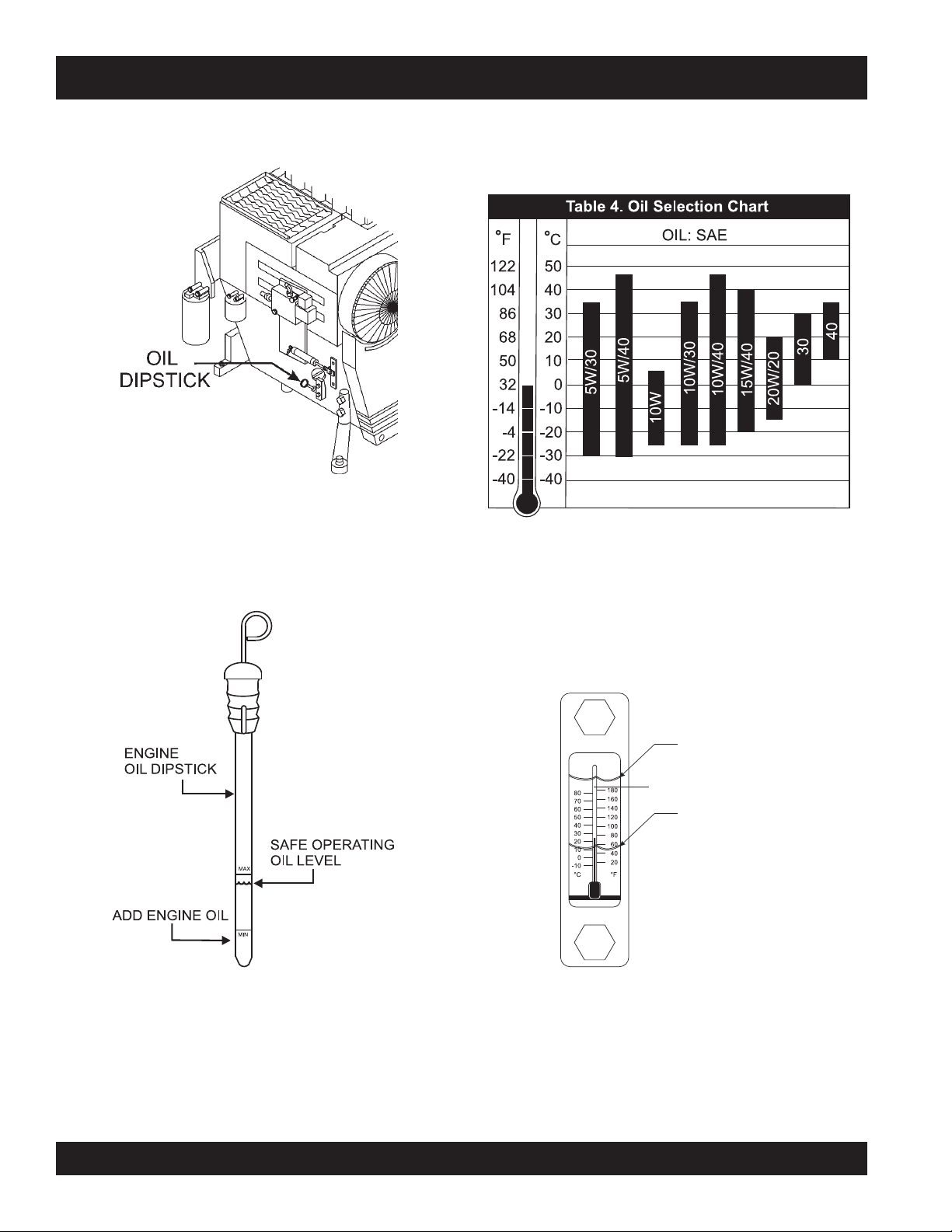
4. Dip Stick – Remove dipstick to determine if the engine
oil level is low. If low add oil as specified in Table 4.
5. V-Belt Cover – Remove this cover to gain access to
the V-belt. When replacing V-belt, use only recommended
type V-belt.
6. Alternator – Provides power to the electrical system.
Replace with only manufacturers recommended
replacement parts.
7. Air Filter/Cover – Prevents dirt and other debris from
entering the fuel system. Release the latches on the
side of the air filter cover to gain access to filter element.
8. Oil Filler Port/Cap – Remove this cap to add engine
oil to the crankcase. Fill with recommended type of oil
as specified in the maintenance section of this manual.
9. Starter/Solenoid – This engine uses a 12 VDC , 2.7kW
(3.7 HP) starter motor with solenoid.
Operating the engine without an air filter, with
a damaged air filter, or a filter in need of
replacement will allow dirt to enter the engine,
causing rapid engine wear.
PAGE 22 — MAYCO LS400/LS500 PUMP — OPERATION AND PARTS MANUAL — REV. #6 (09/19/11)
LS400/LS500 PUMP — INSPECTION
CAUTION - GENERAL SAFETY GUIDELINES
NEVER operate the pump in a
confined area or enclosed area
structure that does not provide ample
free flow of air
NEVER operate the pumps's engine
with the engine hood removed. The
possibility exists of
and
clothing
the V-belt, causing injury and bodily
harm.
NEVER place hands or feet inside the
ALWAYS make while the engine is running. ALWAYS
shut down the engine before performing any kind of
maintenance service on the pump.
.
ALWAYS wear approved
hearing
operating the pump .
hands, long hair
becoming entangled with
protection before
,
eye
and
hopper
.
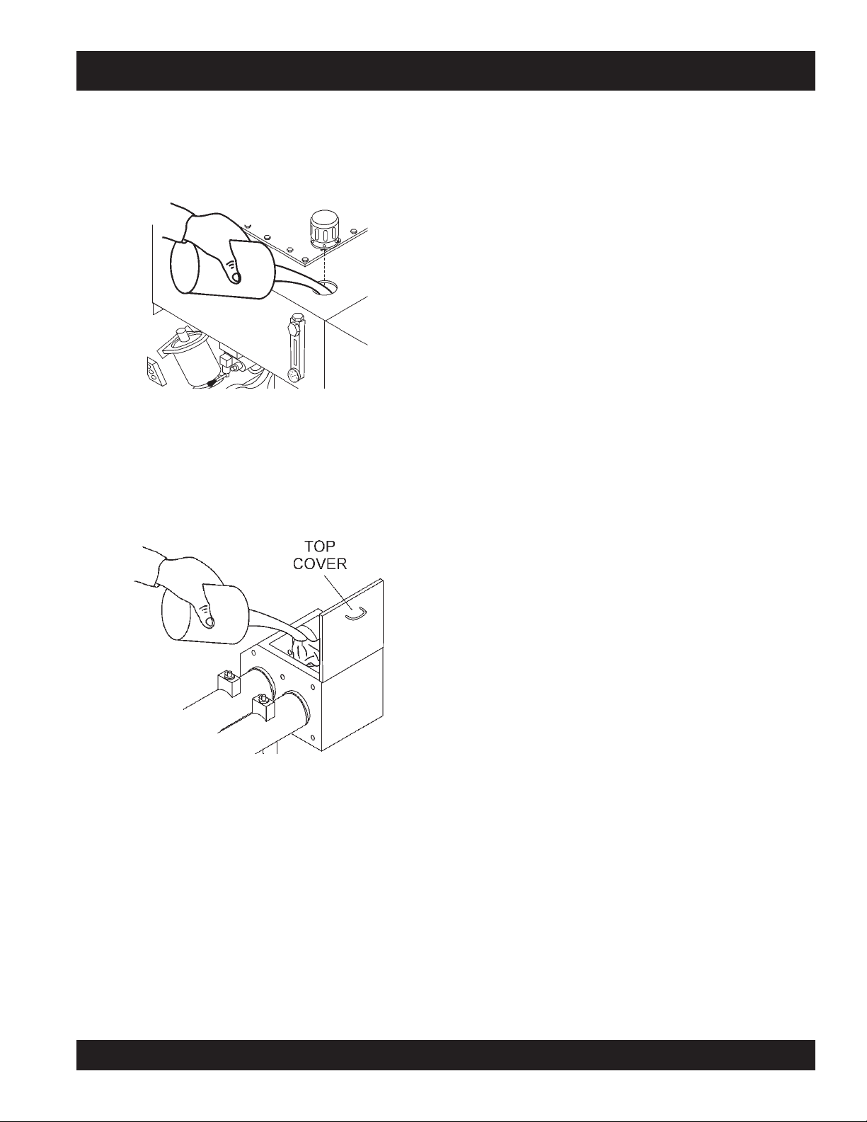
FUEL CHECK
1. Check the fuel gauge built into the fuel tank cap
(Figure 8) to determine if the pump's engine fuel is low.
Refuel as needed.
WARNING - EXPLOSIVE FUEL
Diesel fuel
its vapors can cause an explosion if
ignited. DO NOT start the engine near
spilled fuel or combustible fluids. DO
NOT fill the fuel tank while the engine is
running or hot.
DO NOT overfill tank, since spilled fuel could ignite if it
comes into contact with hot engine parts or sparks from
the ignition system. Store fuel in approved containers,
in well-ventilated areas and away from sparks and
flames. NEVER use fuel as a cleaning agent.
is extremely flammable, and
See Figures 5, 6, and 7 for the location of
any control or component referenced in this
section.
BEFORE STARTING
1. Read safety instructions at the
beginning of manual.
2. Clean the
larly the engine cooling air inlet, and heat exchanger.
3. Check the
replace air filter with a new one as required.
4. Check fastening nuts and bolts for tightness.
WARNING - EXPLOSIVE FUEL
Handle fuel safely. Diesel fuel is highly
can be dangerous if
refueling. DO NOT attempt to refuel pump if the engine
is hot or running. ALWAYS allow engine to
refueling.
entire pump
air filter
, removing dirt and dust, particu-
for dirt and dust. If air filter is dirty,
mishandled. DO NOT
flammable
smoke
cool
before
and
while
Figure 8. Fuel Cap Gauge
2. If fuel is low, remove fuel filler cap and fill with
diesel fuel
(Figure 9).
Figure 9. Adding Diesel Fuel
#2
MAYCO LS400/LS500 PUMP — OPERATION AND PARTS MANUAL — REV. #6 (09/19/11) — PAGE 23
LS400/LS500 PUMP — INSPECTION
ENGINE OIL CHECK
1. Remove the engine oil dipstick from its holder
(Figure 10).
6. The oil listed in Table 4 is recommended to ensure better
engine performance. Use class CD or higher grade motor
oil.
Figure 10. Engine Oil Dipstick
2. Make sure pump/engine is placed on level ground.
3. Pull the engine oil dipstick (Figure 11) from its holder.
HYDRAULIC OIL CHECK
1. Determine if the hydraulic oil level is low by observing
the level of the oil in the Hydraulic Oil Sight Glass
(Figure 12).
Figure 11. Engine Oil Level
4. Verify that oil level (Figure 11) is maintained between
the two notches on the dipstick.
5. If the pump's engine oil is low, fill engine crankcase
with lubricating oil through filler hole, but DO NOT overfill.
PAGE 24 — MAYCO LS400/LS500 PUMP — OPERATION AND PARTS MANUAL — REV. #6 (09/19/11)
NORMAL OIL LEVEL
HYDRAULIC OIL TEMPERATURE
MINIMUM OIL LEVEL
Figure 12. Hydraulic Oil Sight Glass
2. If the hydraulic oil level is low, remove the cap just above
the oil level sight glass (Figure 13) and add the correct
amount of hydraulic oil to bring the hydraulic oil level to
a normal safe operating level. (Use Shell oil Tellus 68 or
Mobil oil DFE26).
Figure 13. Hydraulic Oil Filler Hole
LS400/LS500 PUMP — INSPECTION
3. Check the oil level in the
with up to 3 gallons of SAE #30 motor oil (Figure 14).
The oil level must be checked daily. The lubrication box
should be serviced as described in the maintenance
section.
Figure 14. Filling the Lubrication Box
lubrication box
. If low, fill
MAYCO LS400/LS500 PUMP — OPERATION AND PARTS MANUAL — REV. #6 (09/19/11) — PAGE 25
LOCATION OF PUMP
1. Place the pump in the best location on the site to pump
concrete efficiently.
2. Lay down the hose in the shortest distance possible.
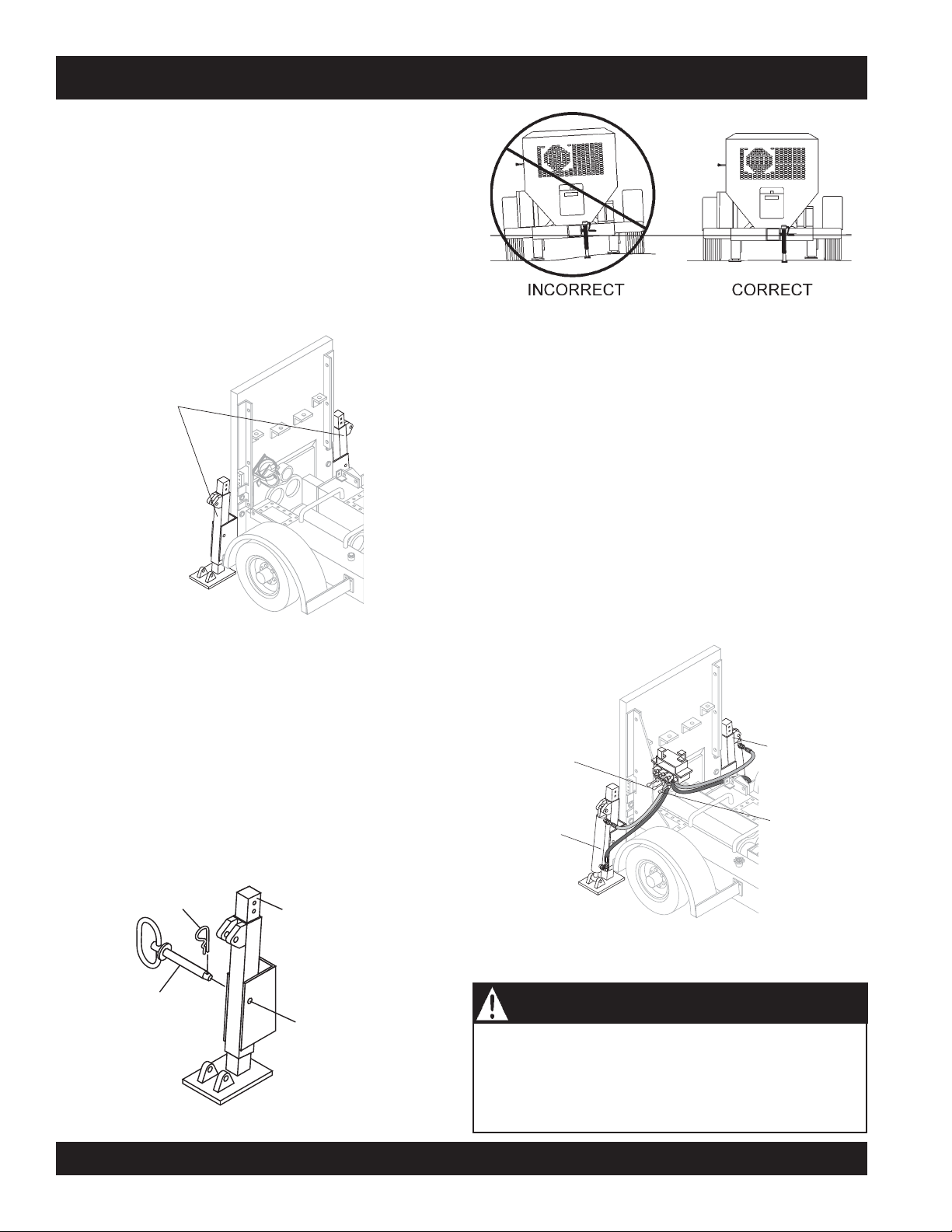
REAR STABILIZER JACKS
To reduce excessive vibration and rocking of the pump, set
the rear stabilizers as follows:
LS400/LS500 PUMP — SET-UP
1. Locate both the left and right rear stabilizer jacks
(Figure 15).
REAR
STABILIZER
JACKS
Figure 17. Rear Stabilizer Stand Deployment
HYDRAULIC REAR STABILIZER JACKS (OPTIONAL)
If your pump comes equipped with hydraulic rear stablizers,
they can be controlled as follows:
1. Push down the middle control lever (see Figure 18) to
extend the right hydraulic rear stabilizer.
2. Push up the middle control lever (see Figure 18) to retract
the right hydraulic rear stabilizer.
3. Push down the rightmost control lever (see Figure 18)
to extend the left hydraulic rear stabilizer.
4. Push up the rightmost control lever (see Figure 18) to
Figure 15. Locating Rear Stabilizer Jacks
2. Remove the
and then
cotter pin
pull
the handle tee to release the stabilizer
from the handle tee bolt eye,
retract the left hydraulic rear stabilizer.
jack (Figure 16).
3. Position both rear stabilizers jacks on firm (not loose)
level
ground (Figure 17).
MIDDLE CONTROL LEVER
(CONTROLS RIGHT
HYDRAULIC STABILIZER)
LEFT HYDRAULIC
STABILIZER JACK
4. Align the hole on the stabilizer jack with the hole on the
frame body and
5. Insert the cotter pin into handle tee bolt eye to lock the
insert
handle tee bolt.
RIGHT HYDRAULIC
STABILIZER JACK
stabilizer jack.
COTTER
PIN
REAR
STABILIZER
STAND
Figure 18. Control Levers for Hydraulic Rear Stabilizers
HANDLE
T-BOLT
BOLT EYE
NEVER place feet under jack while operating.
ALWAYS retract rear stabilizer jacks prior to towing.
ALWAYS retract rear stabilizer jacks prior to servicing to
Figure 16. Rear Stabilizer Jack
PAGE 26 — MAYCO LS400/LS500 PUMP — OPERATION AND PARTS MANUAL — REV. #6 (09/19/11)
relieve load (working pressure).
RIGHTMOST
CONTROL LEVER
(CONTROLS LEFT
HYDRAULIC
STABILIZER)
WARNING - REAR STABILIZER SAFETY
LS400/LS500 PUMP — START-UP PROCEDURE
STARTING PROCEDURE
4. Place the
position (Figure 22).
WARNING - GENERAL SAFETY GUIDELINES
DO NOT attempt to operate this concrete pump until
FORWARD REVERSE
the Safety, General Information and Inspection
sections have been read and understood.
Figure 22. Direction Control Switch (FORWARD)
5. To start the engine, insert the key (Figure 23) into the
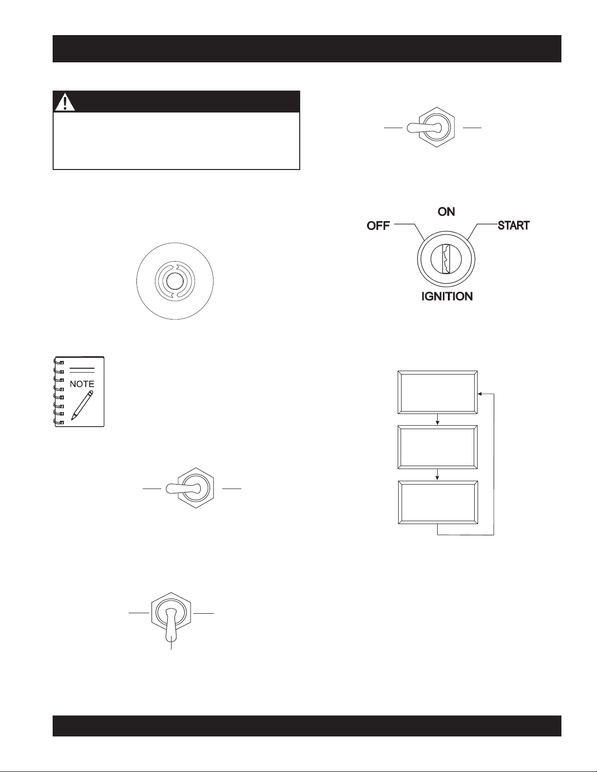
1. Locate the Emergency Stop Switch (Figure 19) on the
ignition switch and turn the key to the ON position.
Hydraulic Pump Control Box. Turn the Emergency Stop
switch clockwise and release (open). This will allow the
engine to start.
n
c
e
y
g
r
e
m
E
Figure 19. Emergency Stop Switch
If the Emergency Stop switch is in the
S
t
o
p
6. When the ignition key is in the ON position, the Digital
Readout Screen (primary) will cycle through 3 displays
as shown in Figure 24.
CLOSED position (stop), engine will not start.
To start the engine, make sure the
Emergency Stop switch is in the OPEN
position (fully extended).
Direction Control Switch
to the FORWARD
Figure 23. Ignition Switch
LS 400 OFF
0000 ENG RPM
BATTERY 12.5 V
LOW OIL PSI
1
2. Turn the
Cylinder Stroke Control Switch
to the
AUTOMATIC position (Figure 20).
AUTOMATIC JOG
Figure 20. Cylinder Stroke
Control Switch (Automatic)
3. Place the
Pumping Control Switch
to the CENTER
OFF position (Figure 21) for normal pumping operation.
LOCAL
CENTER
OFF
REMOTE
Figure 21. Pumping Control Switch (OFF)
LS 400 OFF
0000 ENG RPM
BATTERY 12.5 V
LOW RPM FAULT
LS 400 OFF
0000 ENG RPM
BATTERY 12.5 V
END OF MESSAGE
1
1
Figure 24. Primary Screen (Ignition Key ON)
7. Turn the key to the START position and listen for the
engine to start. In warm weather let engine warm up for
5 minutes. In cold weather let engine warm up for 10
minutes.
MAYCO LS400/LS500 PUMP — OPERATION AND PARTS MANUAL — REV. #6 (09/19/11) — PAGE 27
LS400/LS500 PUMP — OPERATION
HOSE LUBRICATION
Before pumping, it is necessary to lubricate the hose.
PUMPING
WARNING - SAFETY GLASSES
This procedure prevents separation and blockages in the
hose. Inspect the lines at all times to prevent problems.
Before concrete is discharged into the hopper, it is suggested
that 3 to 4 gallons of water be sprayed into the hopper,
followed by approximately 5 gallons of a creamy cement and
water slurry (1/2 bag of cement to 5 gallons of water).
Getting the concrete to flow through the
hose at the start of the pumping cycle
can be one of the most critical operations of the pour.
1. Place the
PRIMING THE PUMP WITH SLURRY MIXTURE
position (Figure 26) for normal pumping operation.
It is CRITICAL to the successful operation of a concrete
pump that the manifold and all delivery hoses, pipes and
elbows are coated with a film of lubrication BEFORE you
attempt to pump concrete.
Safety glasses MUST be worn at
all times when operating the pump.
Failure to follow safety guidelines
can result in
A well-planned location of the pump and
routing of the hose before starting a pour may
save subsequent moves throughout the job.
Pumping Control Switch
LOCAL
serious
injury.
to the LOCAL
REMOTE
Failure to properly prepare the pump and system will result
in a “dry pack” of concrete, blocking the shuttle valve tube
or delivery line.
Figure 26. Pumping Control Switch (LOCAL)
1. Connect the entire delivery system to the pump. Pour 5
gallons of water and a bag of raw cement into the hopper.
2. Place the
Direction Control Switch
to the REVERSE
position (Figure 25). This will mix the water and cement
2. Slide the
right to increase the volume to approximately 10 strokes
per minute. Sliding the volume control to the left will
decrease
into slurry.
FORWARD
Figure 25. Direction Control Switch (REVERSE)
REVERSE
A
thumping
The thumping sound represents the number of strokes
3. Mix the slurry to the consistency of a smooth batter.
4. Position the first ready-mix truck at the hopper. Check
the concrete. DO NOT discharge concrete into hopper
at this time.
5. Place the
Direction Control Switch
in the FORWARD
per minute (volume) of the pump.
3. Scroll through the
switch to go to Screen 7 (Figure 28). This screen will
show the volume in strokes per minute.
position. This will start the flow of the slurry to the hoses.
6. Keep the slurry flowing until most of it is pumped out.
However, make sure that some slurry is left on the hopper
when concrete is first discharged from the ready-mix
truck.
CENTER
OFF
Volume Control Switch
(Figure 27) to the
pump volume.
_
DECREASE
VOLUME
+
INCREASE
VOLUME
Figure 27. Volume Control
sound (cylinder stroke) should be heard.
Digital Readout Screen
THROTTLE ON
with the scroll
7
STROKES: 100
STROKES/MIN 10.0
YDS/HR 0.0
Figure 28. Strokes Per Minute Display
PAGE 28 — MAYCO LS400/LS500 PUMP — OPERATION AND PARTS MANUAL — REV. #6 (09/19/11)
LS400/LS500 PUMP — OPERATION
4. Let the pump cycle until the hydraulic oil temperature
(Figure 29) is approximately 50° to 60° F.
HYDRAULIC OIL
TEMPERATURE
Figure 32. Hopper Remixer Blades (Rotation)
Figure 29. Hydraulic Oil Temperature Gauge
5. The Accumulator Pressure Gauge (Figure 30) should
read approximately 1750 pounds per square inch (psi).
Figure 30. Accumulator
Pressure Gauge
6. Push the Hopper Remixer Control Lever DOWNWARD
(Figure 31). The Hopper Remixer Control lever is located
to the left of the Hydraulic Temperature gauge. Observe
that the blades (Figure 32) inside the hopper are turning
in a clockwise direction (FORWARD). To turn the blades
in a counterclockwise direction (REVERSE), push the
Hopper Remixer Control lever UPWARD (Figure 31).
7. Slide the
Volume Control Switch
(Figure 27) to the
right to increase the volume to 25-30 strokes per minute.
Slowly discharge the concrete from the ready-mix truck
into the hopper and completely fill it. Keep the pump
running continuously until concrete is discharging at the
end of the delivery system. If the pump is stopped during
this procedure, a blockage may occur.
CAUTION - HOSE/LINE BLOCKAGE
If hoses or lines are
lines are
kinked
blocked
for any reason, or if the
when starting up or during the pumping
cycle, the pump pressure could straighten out the kink
or force out the blockage. This rapid surge of material
could cause the lines to
whip
or
move
in a manner
that could cause injury to personnel.
8. It is important that once the slurry procedure is
completed, and concrete is flowing through the hose,
DO NOT stop the pour until all the slurry is pumped out
and the concrete has reached the end of the hose. The
only time to stop the pump during the priming procedure
is if a blockage occurs.
9. If it is necessary to replace or add a section of delivery
system, after the initial lubrication procedure, wet the
inside area of the hose, pipe or elbow with 5 gallons of
water per 25 foot length, before adding it to the system.
When pumping long distance or pumping stiff
mixes, you can expect a drop in volume
compared to shorter lines and wetter mixes
due to the change in valve efficiency or
cavitation.
Figure 31. Hopper Remixer Control Lever
MAYCO LS400/LS500 PUMP — OPERATION AND PARTS MANUAL — REV. #6 (09/19/11) — PAGE 29
LS400/LS500 PUMP — OPERATION
REMOTE CONTROL (OPTIONAL)
The LS400/LS500 Concrete Pump has a remote control
feature that allows the pump to be remotely controlled. If
desired, the pump can be operated via a receiver/transmitter
4. Reinstall the control panel and tighten the 2 screws.
5. On the top of the unit, to the right of the control box
(Figure 36), hammer out the knock-out hole and install
the remote antenna.
(radio) or a hardwire method, which utilizes a 25-ft. extension
cable. Contact MQ Sales Department to order remote control.
Radio Remote Control
KNOCK-OUT
Installation of the Radio Remote Control Assembly
HOLE
1. Remove the two screws on the digital control panel of
the pump. See Figure 33.
REMOVE 2 SCREWS
SCR
OLL
RESET
SET
V
R
G
E
D
E
M
O
ECREA
N
E
L
C
U
Y
M
SE
S
E
T
O
P
IN
CREASE
F
L
D
O
FO
I
R
W
R
E
WARD
C
T
I
O
N
REVE
RSE
C
A
O
U
O
TOM
N
F
LOCAL
T
F
A
R
TIC
O
L
O
N
RE
JOG
MOT
CENT
E
S
ER
OF
T
A
F
R
C
T
YLINDE
I
G
N
JOG“A”
RST
I
T
I
O
ROKE
N
JOG“B”
R
E
M
O
T
E
CONTROL BOX
ANTENNA
CONNECTOR
CABLE
Figure 33. Removing Screws from Control Panel
2. Tilt and slowly pull out the control panel and place on
top of box to gain access inside the box. See Figure 34.
6. Connect the antenna cable to the connector on the rear
of the control box (Figure 36).
Radio Remote Control Buttons Operation
ANTENNA
REAR OF
CONTROL BOX
CONTROL BOX
CONNECTOR
Figure 36. Antenna Installation
The pumping operation can be performed by radio remote
control (Figure 37). Before using remote control, move the
Pumping Control Switch on the control box to the REMOTE
position. The buttons on the remote control have the following
functions.
ON/OFF - Turns the power on or off. When power is on the
power LED lights red. If the battery LED turns red, 9V battery
needs to be replaced.
Figure 34. Pulling Out Control Panel
3. Install the wireless remote module with the 2 screws
and nuts provided inside the control panel. Connect the
3-wire connector from the wireless remote module to
the electronic control unit. See Figure 35.
E-STOP - Turns off the pump completely in an emergency.
PUMP ON/OFF - Starts and stops the forward pumping.
PUMP REV - momentarily pumps in reverse direction.
VOLUME (+) - used to increase the pumping volume.
VOLUME (-) - used to decrease the pumping volume.
SCREWS AND NUTS
ELECTRONIC
CONTROL
UNIT
WIRELESS
REMOTE
MODULE
CONNECTOR
Figure 35. Installing Remote Control Module
ON
E-STOP
OFF
POWER LED
NOTE: OLDER MODELS
MAYINDICATE
FLOW
INSTEAD OF
VOLUME
BATTERY LED
PUMP
PUMP
ON/OFF
REV
VOLUME VOLUME
Figure 37. Radio Remote Control
PAGE 30 — MAYCO LS400/LS500 PUMP — OPERATION AND PARTS MANUAL — REV. #6 (09/19/11)
 Loading...