


OPERATION AND PARTS MANUAL
WHISPERWELD™
MODEL SDW-225SS
WELDER/GENERATOR
(KUBOTA DIESEL ENGINE)
PARTS LIST NO. D2845300004A
Revision #2 (10/07/05)
THISRevisionMANUAL#1MUST(07/13/01)ACCOMPANY
THE EQUIPMENT AT ALLTIMES.

SDW-255SS — PROPOSITION 65WARNING
Diesel engine exhaust and some of
PAGE 2 —SDW-225SS WELDER/GENERATOR— OPERATION & PARTS MANUAL — REV. # 2 (10/07/05)

NOTE PAGE
SDW-225SS WELDER/GENERATOR — OPERATION & PARTS MANUAL — REV. #2 (10/07/05) — PAGE 3

SDW-255SS —TABLE OF CONTENTS
Multiquip SDW-225SS
Welder/Generator
Proposition 65 Warning ............................................. |
|
2 |
Table Of Contents ..................................................... |
|
4 |
Parts Ordering Procedures ....................................... |
|
5 |
Safety Message Alert Symbols .............................. |
|
6-7 |
Rules For Safe Operation .................................... |
|
8-11 |
Operation and Safety Decals ............................. |
|
12-13 |
Specifications .......................................................... |
|
14 |
General Information ................................................ |
|
15 |
Dimensions ............................................................. |
|
16 |
Controls and Indicators ...................................... |
|
17-18 |
Trailer-10 Maintenance ...................................... |
|
19-23 |
WKT225A Wheel Kit Assembly .......................... |
|
24-25 |
Installation ............................................................... |
|
26 |
Pre-Setup ........................................................... |
|
27-29 |
Instrumentation ....................................................... |
|
30 |
Load Application ..................................................... |
|
31 |
Welder Operating Instructions ........................... |
|
32-35 |
Engine Operating Instructions ................................ |
|
36 |
Maintenance ........................................................... |
|
37 |
Preparation For Long Term Storage ....................... |
|
38 |
Generator Wiring Diagram ..................................... |
|
39 |
Engine Wiring Diagram ........................................... |
|
40 |
Troubleshooting Welder .......................................... |
|
41 |
Troubleshooting (Engine and Generator) .......... |
42-43 |
|
Troubleshooting (Engine) ................................... |
|
44-45 |
Explanation Of Parts Section Remarks................... |
46 |
|
Suggested Spare Parts ........................................... |
|
47 |
Generator Assembly .......................................... |
|
48-49 |
Control Panel Assembly ..................................... |
|
50-51 |
Electric Parts Assembly...................................... |
|
52-53 |
Engine and Radiator Assembly.......................... |
|
54-55 |
Battery Assembly ............................................... |
|
56-57 |
Muffler Assembly ............................................... |
|
58-59 |
Fuel Tank Assembly ........................................... |
|
60-61 |
Enclosure Assembly........................................... |
|
62-63 |
Enclosure (Rubber Seals) .................................. |
|
64-65 |
Name Plate and Decals ..................................... |
|
66-67 |
Specification and part |
|
|
number are subject to |
|
|
change |
without |
|
notice. |
|
|
Kubota Z482-EB Engine
Crankcase Assembly ......................................... |
68-69 |
Oil Pan Assembly ............................................... |
70-71 |
Cylinder Head Assembly .................................... |
72-73 |
Gearcase Assembly ........................................... |
74-75 |
Head Cover Assembly ....................................... |
76-77 |
Oil Filter Assembly ............................................. |
78-79 |
Dipstick and Guide Assembly ............................ |
80-81 |
Main Bearing Case Assembly ............................ |
82-83 |
Camshaft and Idle Gear Shaft Assembly........... |
84-85 |
Piston and Crankshaft Assembly ....................... |
86-87 |
Flywheel Assembly ............................................ |
88-89 |
Fuel Camshaft and Governor Shaft Assembly ..90-91 |
|
Engine Stop Lever Assembly ............................. |
92-93 |
Stop Solenoid Assembly .................................... |
94-95 |
Injection Pump 1. Assembly ............................... |
96-97 |
Injection Pump 2. Assembly ............................... |
98-99 |
Speed Control Plate Assembly ..................... |
100-101 |
Nozzle Holder and Glow Plug Assembly....... |
102-103 |
Nozzle Holder Assembly ............................... |
104-105 |
Fork Lever Assembly .................................... |
106-107 |
Fuel Filter Assembly ..................................... |
108-109 |
Fuel Pump Assembly .................................... |
110-111 |
Dynamo and Pulley Assembly ...................... |
112-113 |
Dynamo Assembly ........................................ |
114-115 |
Starter 1 Assembly ....................................... |
116-117 |
Starter 2 Assembly ....................................... |
118-119 |
Oil Switch/Thermometer and Plug Assembly 120-121 |
|
Water Flange and Thermostat Assembly...... |
122-123 |
Water Pump Assembly .................................. |
124-125 |
Water Pipe Assembly .................................... |
126-127 |
Fan Assembly................................................ |
128-129 |
Valve and Rocker Arm Assembly .................. |
130-131 |
Inlet Manifold Assembly ................................ |
132-133 |
Exhaust Manifold Assembly .......................... |
134-135 |
Glow Plug/Glow Lamp and Timer Assembly . 136-137 |
|
Starter Switch Assembly ............................... |
138-139 |
Trailer-10 Assembly ...................................... |
140-141 |
WKT225A Wheel Kit Assembly ..................... |
142-143 |
Terms and Conditions Of Sale — Parts ................ |
144 |
PAGE 4 —SDW-225SS WELDER/GENERATOR— OPERATION & PARTS MANUAL — REV. # 2 (10/07/05)
Effective:June 1st, 2005 |
PARTS ORDERING PROCEDURES |
www.multiquip.com


Ordering parts has never been easier!
Choose from three easy options:
Best Deal! Order via Internet (Dealers Only):
Order parts on-line using Multiquip’s SmartEquip website!
■View Parts Diagrams
■Order Parts
■Print Specification Information
Goto www.multiquip.com and click on
Order Parts to log in and save!
If you have an MQ Account, to obtain a Username and Password, E-mail us at: parts@multiquip.com.
To obtain an MQ Account, contact your
District Sales Manager for more information.
Use the internet and qualify for a 5% Discount on Standard orders for all orders which include complete part numbers.*
Note: Discounts Are Subject To Change
|
Order via Fax (Dealers Only): |
|
|
|
|
|
|
|
|
|
|
|
|
|
|
|
|
|
|
|
|
|
|
|
|
|
|
|
|
|
|
|
|
Fax your order in and qualify for a 3% Discount |
|||||||||||||||||||||||||||
|
|
|
||||||||||||||||||||||||||||
|
||||||||||||||||||||||||||||||
|
All customers are welcome to order parts via Fax. |
|
|
on Standard orders for all orders which include |
||||||||||||||||||||||||||
|
||||||||||||||||||||||||||||||
|
|
|||||||||||||||||||||||||||||
|
Domestic (US) Customers dial: |
|
|
complete part numbers.* |
||||||||||||||||||||||||||
|
||||||||||||||||||||||||||||||
1-800-6-PARTS-7 (800-672-7877)
Note: Discounts Are Subject To Change
|
|
|
|
|
|
|
|
|
|
|
|
|
|
|
|
|
|
|
|
|
Order via Phone: Domestic (US) Dealers Call: |
|||||||||||||||||||||||||||||||||||||||||||
|
|
|
|
|
|
|
|
|
|
|
|
|
|
|
|
|
|
|
|
|
||||||||||||||||||||||||||||||||||||||||||||
|
|
|
|
|
|
|
|
|
|
|
|
|
|
|
|
|
|
|
|
|
|
|
|
|
|
|
|
|
|
|
|
|
1-800-427-1244 |
|
|
|
|
|
|
|
|
|
|
|
|
|
|
|
|
|
|
|
|
|
|
|||||||||
|
|
|
|
|
|
|
|
|
|
|
|
|
|
|
|
|
|
|
|
|
|
|
|
|
|
|
|
|
|
|
|
|
|
|
|
|
|
|
|
|
|
|
|
|
|
|
|
|
|
|
|
|
|
|
|
|
|
|
|
|
|
|
|
|
|
|
|
|
|
|
|
|
|
|
|
|
|
|
|
|
|
|
|
|
|
|
|
|
|
|
|
|
|
|
|
|
|
|
|
|
|
|
|
|
|
|
|
|
|
|
|
|
|
|
|
|
|
|
|
|
|
|
|
|
|
|
|
|
|
|
|
|
Non-Dealer Customers: |
|
|
|
|
|
|
|
|
|
|
|
|
|
International Customers should contact |
|
||||||||||||||||||||||||||||||||||||||||||||||
|
|
|
|
|
|
|
|
|
|
|
|
|||||||||||||||||||||||||||||||||||||||||||||||||||||
|
|
|
|
|
|
|
|
|
|
|
|
|||||||||||||||||||||||||||||||||||||||||||||||||||||
|
|
|
Contact your local Multiquip Dealer for |
|
|
|
|
|
|
|
|
|
|
|
|
|
|
|||||||||||||||||||||||||||||||||||||||||||||||
|
|
|
|
|
|
|
|
|
|
|
|
|
|
|
|
|
||||||||||||||||||||||||||||||||||||||||||||||||
|
|
|
|
|
|
|
|
|
|
|
|
|
|
|
|
their local Multiquip Representatives for |
|
|||||||||||||||||||||||||||||||||||||||||||||||
|
|
|
parts or call 800-427-1244 for help in |
|
|
|
|
|
|
|
|
|
|
|
|
|
|
|||||||||||||||||||||||||||||||||||||||||||||||
|
|
|
|
|
|
|
|
|
|
|
|
|
|
|
|
Parts Ordering information. |
|
|||||||||||||||||||||||||||||||||||||||||||||||
|
|
|
locating a dealer near you. |
|
|
|
|
|
|
|
|
|
|
|
|
|
|
|||||||||||||||||||||||||||||||||||||||||||||||
|
|
|
|
|
|
|
|
|
|
|
|
|
|
|
|
|
|
|
|
|
|
|
|
|
|
|
|
|
|
|
|
|
|
|
|
|
|
|
||||||||||||||||||||||||||
|
|
|
|
|
|
|
|
|
|
|
|
|
|
|
|
|
|
|
|
|
|
|
|
|
|
|
|
|
|
|
|
|
|
|
|
|
|
|
|
|
|
|
|
|
|
|
|
|
|
|
|
|
|
|
|
|
|
|
|
|
|
|
|
|
|
|
|
|
|
|
|
|
|
|
|
|
When ordering parts, please supply: |
||||||||||||||||||||||||||||||||||||||||||||||||||||
|
Dealer Account Number |
Specify Preferred Method of Shipment: |
|
|
Dealer Name and Address |
Fed Ex/UPS |
DHL |
|
Shipping Address (if different than billing address) |
■ Priority One |
Truck |
■ Ground |
|
||
|
Return Fax Number |
|
|
■ Next Day |
|
||
|
Applicable Model Number |
|
|
■ Second/ThirdDay |
|
||
Quantity, Part Number and Description of Each Part
Unless otherwise indicated by customer, all orders are treated asStandard Orders and will ship NOTE within24hours.WewillmakeeveryefforttoshipAirShipmentsthesamedaytheorderisreceived,
if received prior to 2PM PST. Stock Orders must be noted on fax or web order form.
WE ACCEPT ALL MAJOR CREDIT CARDS!
SDW-225SS WELDER/GENERATOR — OPERATION & PARTS MANUAL — REV. #2 (10/07/05) — PAGE 5
SDW-225SS — SAFETY MESSAGE ALERT SYMBOLS
FORYOUR SAFETY ANDTHE SAFETY OF OTHERS! |
|
HAZARD SYMBOLS |
|
|
|
Safety precautions should be followed at all times when operating this equipment. Failure to read and understand the Safety Messages and Operating Instructions could result in injury to yourself and others.
This Owner's Manual has been developed to provide complete instructions for the safe and efficient operation of the MQ Model SDW-225SS Welder/Generator. Refer to the engine manufacturer's instructions for data relative to its safe operation.
Before using this welder/generator, ensure that the operating individual has read and understands all instructions in this manual.
SAFETY MESSAGE ALERT SYMBOLS
The three (3) Safety Messages shown below will inform you about potential hazards that could injure you or others. The Safety Messages specifically address the level of exposure to the operator, and are preceded by one of three words: DANGER,
 DANGER
You WILL be KILLED or SERIOUSLY INJURED if you DO NOT follow these directions.
 WARNING
You CAN be KILLED or SERIOUSLY INJURED if you DO NOT follow these directions.
 CAUTION
You CAN be INJURED if you DO NOT follow these directions.
Potential hazards associated with the operation of this equipment will be referenced with Hazard Symbols which appear throughout this manual, and will be referenced in conjunction with Safety Message Alert Symbols.
 WARNING Lethal Exhaust Gas Hazards
Engine exhaust gases contain poisonous carbon monoxide. This gas is colorless and odorless, and can cause death if inhaled. NEVER operate this equipment in a confined area or enclosed structure that does not provide ample free flow air.
 WARNING Explosive Fuel Hazards
Diesel Fuel is extremely flammable, and its vapors can cause an explosion if ignited. DO NOT start the engine near spilled fuel or combustible fluids.
DO NOT fill the fuel tank while the engine is running or hot. DO NOT overfill tank, since spilled fuel could ignite if it comes into contact with hot engine parts or sparks from the ignition system. Store fuel in approved containers, in well-ventilated areas and away from sparks and flames.
|
WARNING |
Burn Hazards |
Engine components can generate extreme heat. To prevent burns, DO NOT touch these areas while the engine is running or immediately after operations. Never operate the engine with heat shields or heat guards removed.
|
WARNING |
Respiratory Hazards |
ALWAYS wear approved respiratory protection when required.
PAGE 6 —SDW-225SS WELDER/GENERATOR— OPERATION & PARTS MANUAL — REV. # 2 (10/07/05)

SDW-225SS — SAFETY MESSAGE ALERT SYMBOLS
|
CAUTION |
Rotating Parts Hazards |
|
|
|
NEVER operate equipment with covers, or guards removed. Keep fingers, hands, hair and clothing away from all moving parts to prevent injury.
 CAUTION Accidental Starting Hazards
ALWAYS place the power source, circuit breakers or ON/OFF switch in the OFF position, when the generators is not in use, unless connected to transfer switch.
 CAUTION Eye and Hearing Hazards
ALWAYS wear approved eye and hearing protection.
|
DANGER |
Refueling Hazard |
|
|
|
|
CAUTION |
Equipment Damage |
|
Hazards |
|
|
|
Other important messages are provided throughout this manual to help prevent damage to your portable generator, other property, or the surrounding environment.
NEVER refuel welder/generator when placed in truck bed with plastic liner.The possibility exists of explosion due to static electricity. When adding fuel, remove welder/ generator from truck bed and place on ground.
SDW-225SS WELDER/GENERATOR — OPERATION & PARTS MANUAL — REV. #2 (10/07/05) — PAGE 7
SDW-225SS — RULES FOR SAFE OPERATION
|
DANGER |
Read this manual! |
|
|
|
Failure to follow instructions in this manual may lead to serious injury or even death! This equipment is to be operated by trained and qualified personnel only!
This equipment is for industrial use only.
The following safety guidelines should always be used when operating the SDW-225SS Welder/Generator:
GENERAL SAFETY
■DO NOT operate or service this equipment before reading this entire manual.
■This equipment should not be operated by persons under
18 years of age.
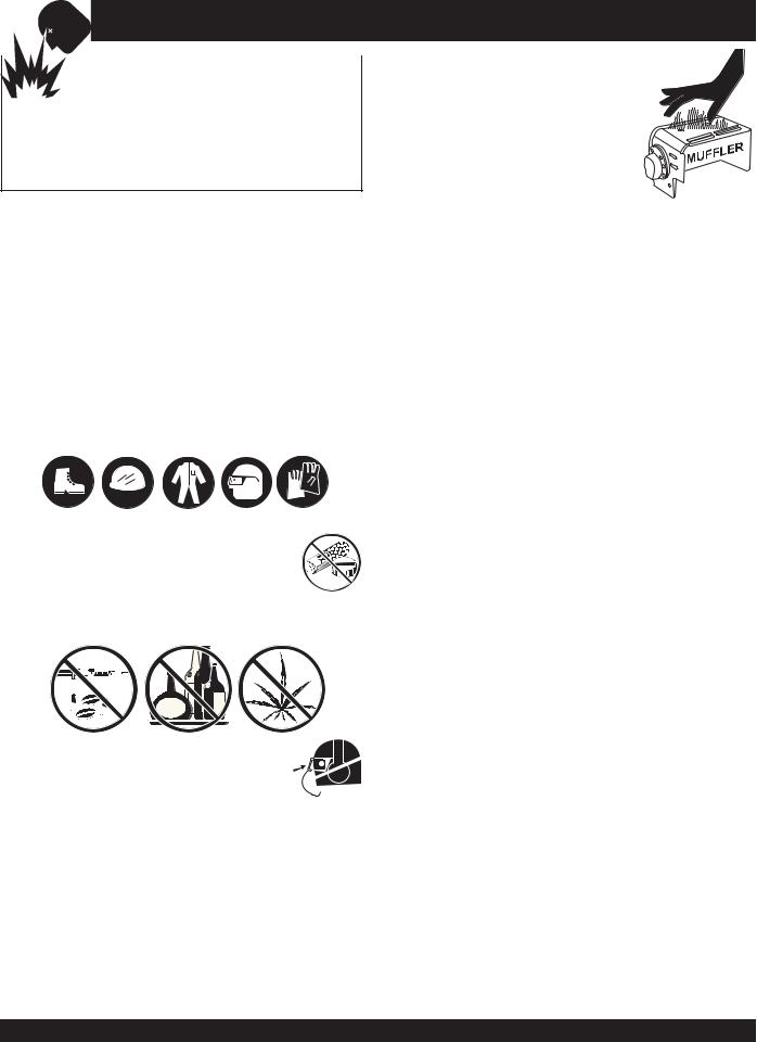
■NEVER operate this equipment without proper protective clothing, shatterproof glasses, steel-toed boots and other protective devices required by the job.
■NEVER operate this equipment when not
feeling well due to fatigue, illness or taking medicine.
■NEVER operate this equipment under the influence of drugs or alcohol.
■ALWAYS wear proper respiratory (mask), 
 hearing and eye protection equipment when
 operating the generator.
■Whenever necessary, replace nameplate, operation and safety decals when they become difficult read.
■Manufacturer does not assume responsibility for any accident due to equipment modifications.
■NEVER use accessories or attachments, which are not recommended by Multiquip for this equipment. Damage to the equipment and/or injury to user may result.
■NEVER touch the hot exhaust manifold, muffler or cylinder. Allow these parts to cool before servicing engine or generators.
■The engine section of this welder/generator requires an adequate free flow of cooling air. NEVER operate the welder/generator in any enclosed or narrow area where free flow of the air is
restricted. If the air flow is restricted it will cause serious damage to the generatorsorengineand may cause injury to people. Remember the welder/generator's engine gives off
DEADLY carbon monoxide gas.
■ALWAYS refuel in a well-ventilated area, away from sparks and open flames.
■ALWAYS use extreme caution when working with flammable liquids. When refueling, stop the engine and allow it to cool.DO NOT smoke around or near the machine. Fire or explosion could result from fuel vapors, or if fuel is spilled on a hot engine.
■NEVER operate the welder/generator in an explosive atmosphere or near combustible materials. An explosion or fire could result causing severe bodily harm or even death.
■NEVER disconnect any "emergency or safety devices". These devices are intended for operator safety. Disconnection of these devices can cause severe injury, bodily harm or even death! Disconnection of any of these devices will void all warranties.
■ALWAYS be sure the operator is familiar with proper safety precautions and operation techniques before using welder/ generator.
PAGE 8 —SDW-225SS WELDER/GENERATOR— OPERATION & PARTS MANUAL — REV. # 2 (10/07/05)

SDW-225SS — RULES FOR SAFE OPERATION
■NEVER leave the welder/generator unattended. Turn off engine when unattended.
■Unauthorized equipment modifications will void all warranties.
■ALWAYS ensure welder/generator is on level ground before use.
■DO NOT place hands or fingers inside welder/generator's engine compartment when engine is running.
■NEVER run engine without air cleaner.Severe engine damage may occur.
■NEVER change or adjust the engine speed which has been set at the factory prior to shipping.
Power Cord Safety
■NEVER let power cables or cords lay in water.
■NEVER stand in water while AC power from the generator is being transfer to a load.
■NEVER use a defective or frayed power cable. Check the cable for cuts in the insulation.
■NEVER use a extension cord that is frayed or damaged where the insulation has been cut.
■ALWAYS make certain that proper power or extension cord has been selected for the job.
Grounding Safety
■ALWAYS make sure that electrical circuits are properly grounded per the National Electrical Code (NEC) and local codes before operating generator. Severe injury or death! by electrocution can result from operating an ungrounded generator.
■ALWAYS make sure the generators are properly grounded to a suitable earth ground (GROUND ROD). See installation in this manual.
■NEVER use gas piping as an electrical ground.
Maintenance Safety
■NEVER lubricate components or attempt service on a running machine.
■HighTemperatures – Always stop engine and allow the engine to cool before adding fuel, oil or performing service and maintenance functions. Contact with hot! components can cause serious burns.
■Keep the machinery in proper running condition.
■Fix damage to the machine immediately and replace any broken parts immediately.
■ALWAYS replace any worn or damaged warning decals.
■ALWAYS store equipment properly when it is not being used. Equipment should be stored in a clean, dry location out of the reach of children and unauthorized personnel.
■The electrical voltage required to operate the generator can cause severe injury or even death through physical contact with live circuits. Turn all circuit breakers OFF before performing maintenance on the generator.
■Dispose of hazardous waste properly.Examples of potentially hazardous waste are used motor oil, fuel and fuel filters.
■DO NOT use food or plastic containers to dispose of hazardous waste.
■DO NOT pour waste, oil or fuel directly onto the ground, down a drain or into any water source.
■Removing the engine oil drain plug while the engine is hot will result in hot oil to gush out of the oil drain plug, therefore causing severescaldingtoanypersonsinthegeneral area of the generator.
■Removingtheradiator plug whiletheengine is hot will result in hot water or coolant to gush out of the radiator, therefore causing severescaldingtoanypersonsinthegeneral area of the generator.
DANGER-ELECTROCUTION HAZARDS
During operation of this generator, there exists the possibility of electrocution, electrical shock or burn, which can cause severe bodily harm or even
DEATH!
To avoid these hazards:
NEVER use damaged or worn cables when connecting equipment to the generator.Make sure power connecting cables are securely connected to the generator’s output receptacles, incorrect connections may cause damage to the generators and electrical
shock.
NEVER grab or touch a live
power cord with wet hands, the possibility exist of electrical
shock, electrocution, and even death!
SDW-225SS WELDER/GENERATOR — OPERATION & PARTS MANUAL — REV. #2 (10/07/05) — PAGE 9
SDW-225SS — RULES FOR SAFE OPERATION
NEVER insert any objects into the output receptacles during operation. This is extremely dangerous. ALWAYS turn-off the generators and place all circuit breakers in the “OFF” position when contact with the
output receptacles is required.There exist the possibility of electrocution, electrical shock or burn, which can cause severe bodily harm or even death!
Backfeed to a utility system can cause electrocution and or property damage. NEVER connect the generator to a building's electrical system without a transfer switch or other approved device. All installations should be performed by a licensed electrician in accordance with all applicable laws and electrical codes. Failure to do so could result in electrical shock or burn causing serious injury or even death!
WeldingSafety
■ALWAYS keep welder in good, clean, dry condition.
■ALWAYS make sure all eledtrical connections are tight, clean, and dry.
■ALWAYS use correct size welding cable.NEVER overload.
■ALWAYS make sure cables, holder and connections are properly insulated.
■ALWAYS cut off power to welders before cleaning machine or making internal adjustments.
■NEVER change polarity while machine is under load.
■ALWAYS observe normal operating care for electrical hazards.
■ALWAYS keep work area neat , clean, and dry.
■ALWAYS dispose hot electrode stubs in a metal container.
■NEVER strike an arc on a compressed gas cylinder.
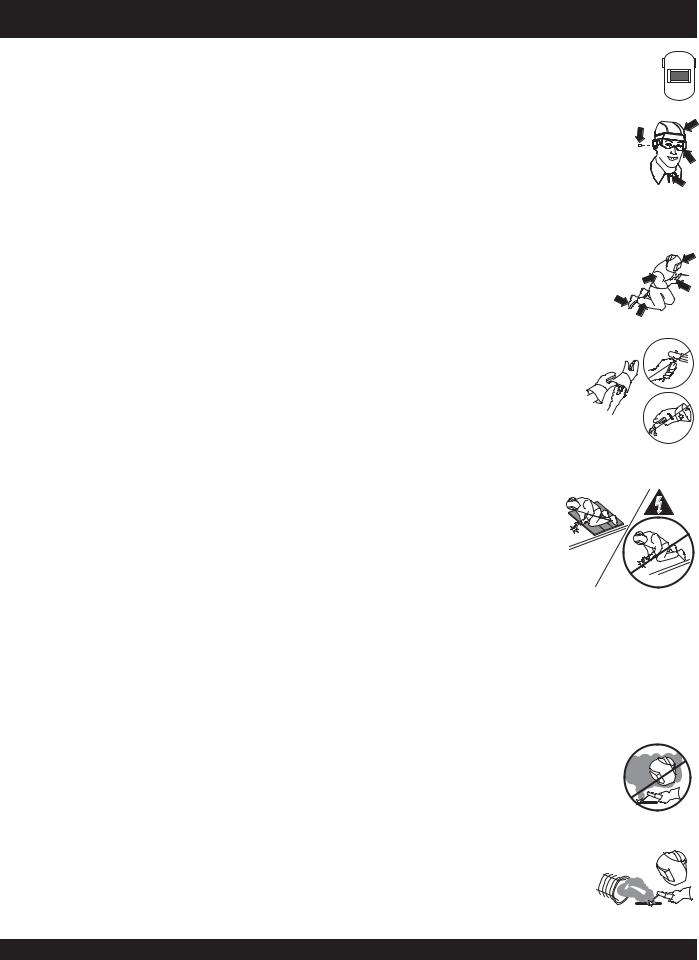
■ ALWAYS protect your eyes from rays of the arc.Wear a head shield with proper filter plates when welding.
■ ALWAYS wear welder cap and approved safety glasses with side shields.ALWAYS use ear protection when welding out of position or in confined spaces.
■ALWAYS wear protective chipping goggles when chipping off weld slag. Chip away from your face.
■ ALWAYS wear complete body protection such as leather gloves, an apron or sleeves to shield against the arc rays and sparks. Button up shirt collar.
■ ALWAYS wear dry, hole-free insulating gloves and body protection. Do not touch electrode with bare hand. Do not wear wet or damaged gloves.
■ALWAYS protect yourself from electric shock by insulating
yourself from work and ground. Use non-flammable, dry insulating material if possible, or use dry rubber mats, dry wood or plywood, or other dry insulating material big enough to cover your full area of contact with the work or ground.
■ALWAYS use a non-reflectingwelding curtain to protect others in the area from arc rays.
■ALWAYS make sure you work area has adequate ventilation and plenty of fresh air. Special precautions are necessary when welding lead, zinc, beryllium copper or cadmium.
■ALWAYS keep your head out of the fumes.
Do not breathe the fumes. Use enough ventilation, exhaust at the arc, or both, to keep fumes and gases from your breathing zone and the general area.
■ALWAYS use enough forced ventilation or loca exhaust (forced suction) at the
arc to remove the fumes from your breathing area.
PAGE 10 —SDW-225SS WELDER/GENERATOR— OPERATION & PARTS MANUAL — REV. # 2 (10/07/05)
SDW-225SS — RULES FOR SAFE OPERATION
■ ALWAYS use a ventilating fan to remove fumes from the breathing zone an welding area.
■ NEVER weld near flammable material. Move flammables at 35 feet (11 meters) away or protect them with flame-proof covers.
■NEVER weld near engine fuel. Engine fuel plus flames or sparks can cause fire or explosion.
■Welding sparks can cause fires.
ALWAYS have a fire extinguisher nearby, and have a trained fire watcher ready to use it.
■NEVER weld on drums, tanks, or any closed containers unless a qualified
person has tested it and declared it or prepared it to be safe.
Emergencies
■ALWAYS know the location of the nearest fire extinguisher.
■ALWAYS know the location of the nearest first aid kit.
■In emergencies always know the location of the nearest phone or keep a phone on the job site. Also know the phone numbers of the nearest ambulance, doctor and fire department. This information will be invaluable in the case of an emergency.
SDW-225SS WELDER/GENERATOR — OPERATION & PARTS MANUAL — REV. #2 (10/07/05) — PAGE 11
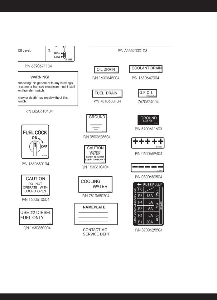
SDW-225SS — OPERATION AND SAFETY DECALS
Machine Safety Decals
The SDW-225SS welder/generator is equipped with a number of safety decals.These decals are provided for operator safety and maintenance information.The illustration below shows these decals as they appear on the machine. Should any of these decals become unreadable, replacements can be obtained from your dealer.
PAGE 12 —SDW-225SS WELDER/GENERATOR— OPERATION & PARTS MANUAL — REV. # 2 (10/07/05)

SDW-225SS — OPERATION AND SAFETY DECALS
SDW-225SS WELDER/GENERATOR — OPERATION & PARTS MANUAL — REV. #2 (10/07/05) — PAGE 13

|
|
|
SDW-225SS — SPECIFICATIONS |
|
|
|
|
|
|
|
|
|
|
|
|
|
Table 1. Specifications |
|
|
|
|
Generator Specifications |
|
|
|
|
|
|
|
|
Model |
|
SDW-225SS |
|
|
|
|
|
|
|
Phase |
|
Single Phase |
|
|
|
|
|
|
|
Wires |
|
3-Wires (Neutral Grounded) |
|
|
|
|
|
|
|
Maximun Output |
|
6000 Watts |
|
|
|
|
|
|
|
Rated Voltage |
|
120/240 Volts |
|
|
|
|
|
|
|
Frequency |
|
60 Hz |
|
|
|
|
|
|
|
Speed |
|
3600 rpm |
|
|
|
|
|
|
|
Power Factor |
|
1.0 |
|
|
|
|
|
|
|
Rating |
|
Continuous |
|
|
|
|
|
|
|
|
Welder Specifications |
|
|
|
|
|
|
|
|
Rated Output Power (CV/CC) |
|
4.0 kW/5.6 kW |
|
|
|
|
|
|
|
Rated Output Voltage (CV/CC) |
|
200 Amps |
|
|
|
|
|
|
|
Rated Output Current (CV/CC) |
|
20/28 Volts |
|
|
|
|
|
|
|
Duty Cycle |
|
100/% |
|
|
|
|
|
|
|
Rated Speed |
|
3600 RPM |
|
|
|
|
|
|
|
Voltage Range |
|
15-28 Volts |
|
|
|
|
|
|
|
Current Range |
|
50-225 Amps |
|
|
|
|
|
|
|
|
Engine Specifications |
|
|
|
|
|
|
|
|
Model |
|
KUBOTA Z-482-EB |
|
|
|
|
|
|
|
Type |
|
Vertical, 4-Cycle |
|
|
|
|
|
|
|
Rated Output |
|
8.9 kW/11.9 HP |
|
|
|
@ 3600 rpm |
|
|
|
|
|
|
|
|
|
|
|
|
|
Displacement |
|
29.23 cu. in (479 cc) |
|
|
|
|
|
|
|
Number of Cylinders |
|
2 |
|
|
|
|
|
|
|
Cooling System |
|
Water-Cooled |
|
|
|
|
|
|
|
Starting System |
|
Electric Start |
|
|
|
|
|
|
|
Fuel Tank Capacity |
|
6.6 gal/25 liters |
|
|
|
|
|
|
|
Coolant Capacity |
|
0.66 gal/2.5 liters |
|
|
|
|
|
|
|
Lube Oil Capacity |
|
0.55 gal/2.1 liters |
|
|
|
|
|
|
|
Fuel Consumption |
|
0.69 gal (2.63 liters)/hr. |
|
|
|
|
|
|
|
Battery |
|
12V-35Ah |
|
|
|
|
|
|
|
Fuel |
|
Diesel Fuel No. 2 |
|
|
|
|
|
|
|
Dimensions (LxWxH) |
|
351 x 389 x 520 mm |
|
|
|
(13.82 x 15.31 x 20.47 in) |
|
|
|
|
|
|
|
|
|
|
|
|
|
Weight |
|
117.1 lbs. (53.1 kg) |
|
|
|
|
|
|
The maximum output of the engine listed above is applicable to supplying electrical power for continuous service at ambient conditions in accordance with SAE Test cord J607. The above ambient conditions are at standard sea level, with a barometric reading of 29.92 inches and a temperature of 60° F.
Generally, the engine output power will decrease 3 1/2% for each 1000 feet of altitude above sea level, and 1% for each 10° F above the standard temperature of 60° F.
PAGE 14 —SDW-225SS WELDER/GENERATOR— OPERATION & PARTS MANUAL — REV. # 2 (10/07/05)

SDW-225SS — GENERAL INFORMATION
SDW-225SS FAMILIARIZATION
Generator
The MQ Power Model SGW-250SS welder/generator can provide 200 amps of welding current when in the CV/DC mode and 225 amps of welding current when in the CC/DC mode. When used as a generator it can provide a maximum of 6,000 watts of AC power.
Control Panel
The control panel is provided with the following:
zOne GFCI 120 volt receptacle, 20 amp (single-phase)
zOne 120 volt receptacle, 30 amp (single-phase)
zOne 120/240 volt receptacle, 30 amp (single-phase)
zMain Circuit Breaker 240V @25 Amps
zCircuit Protector Breaker (GFCI) 120V @20 Amps
zIdle Control Switch
zStarter Switch
zWarning Lamp Unit
zHour Meter
zGroundTerminal
zDC (Welding) OutputTerminal
Engine Protection System
Engine protection fail safe features are provided in the event of low oil pressure, high coolant temperature and failure of the battery to charge. If any of the above conditions occur while operating the generator it will cause a complete unit shut down.
Battery Charge Alarm
This unit is equipped with a protective device that signals an alarm and automatically stops the engine when the battery cannot be charged by the alternator.
WaterTemperature Alarm
This unit is equipped with an apparatus that signals an alarm and automatically stops the engine when the cooling water temperature becomes abnormally high. This apparatus will not function properly if the machine is operated with less than the proper amount of coolant.
Oil Pressure Warning Alarm
In the event of low oil pressure (engine), this welder/ generator is equipped with an engine protection fail safe system. If low oil pressure is detected while operating the welder/generator, the engine protection system will shut down the engine.
If this condition (low oil pressure) should occur, please refer to the engine troubleshooting table in this manual.
Welder Protection System
In the event of an overload, this welder/generator is equipped with a welder protection system. If an overload is detected while operating the welder/generator, the welder protection system will shut down the engine.
Open Delta Excitation System
The SDW-225SS generator is equipped with the state of the art "Open-Delta" excitation system. The open delta system consist of an electrically independent winding wound among stationary windings of the AC output section.
There are four connections of the open delta A, B, C and D.
During steady state loads, the power from the voltage regulator is supplied from the parallel connections of A to B,
A to D, and C to D. These three phases of the voltage input to the voltage regulator are then rectified and are the excitation current for the exciter section.
When a heavy load, such as a motor starting or a short circuit occurs, the automatic voltage regulator (AVR) switches the configuration of the open delta to the series connection of B to C. This has the effect of adding the voltages of each phase to provide higher excitation to the exciter section and thus better voltage response during the application of heavy loads.
The connections of the AVR to the AC output windings are for sensing only. No power is required from these windings.
The open-delta design provides virtually unlimited excitation current, offering maximum motor starting capabilities. The excitation does not have a "fixed ceiling" and responds according the demands of the required load.
Engine
The SDW-225SS is powered by a 4-cycle KUBOTA diesel engine.This engine is designed to meet every performance requirement for generator. Refer to Table 1 for engine specifications.
In keeping with Multiquip's policy of constantly improving its products, the specifications quoted herein are subject to change without prior notice.
Figures 2 and 3 show the basic controls and indicators for the SDW-225SS welder/generator.
SDW-225SS WELDER/GENERATOR — OPERATION & PARTS MANUAL — REV. #2 (10/07/05) — PAGE 15
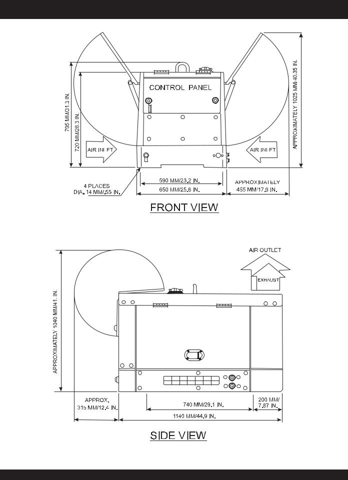
SDW-225SS — DIMENSIONS
Figure 1. SDW-225SS Dimensions
PAGE 16 —SDW-225SS WELDER/GENERATOR— OPERATION & PARTS MANUAL — REV. # 2 (10/07/05)
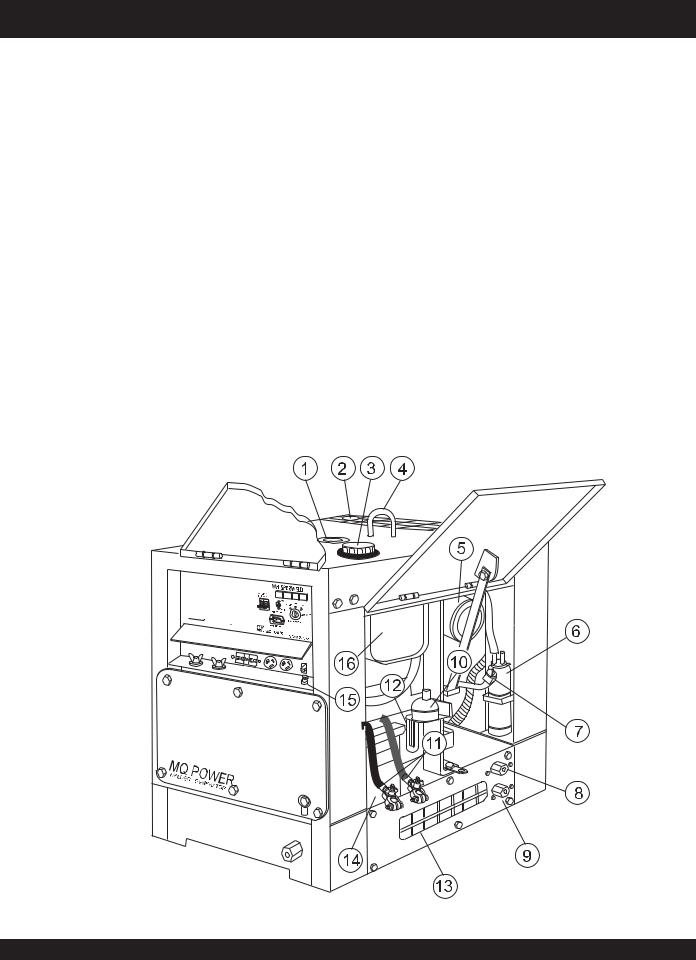
SDW-225SS — CONTROLS AND INDICATORS
Figures 2 and 3 show the location of the controls and indicators. The functions of each control or indicator is described below and on the preceding page.
1.Fuel Gauge – Indicates the amount of fuel in the fuel tank.
2.Air Outlet and Exhaust – Allows engine exhaust to exit the generator into the open air.NEVER block this opening.
3.Fuel Cap – Remove this cap to add fuel. Add only #2 diesel fuel. Always keep an adequate amount of fuel in the tank. DO NOT top off. Wipe up any spilled fuel immediately.
4.Lifting Hook – Use this hook to lift the generator.
5.Engine Air Cleaner – Prevents dirt and other debris from entering the fuel system. Lift locking latch on air filter cannister to gain access to filter element.
6.Overflow Bottle – Supplies coolant to the radiator when radiator coolant level is low.Fill to indicated level as shown on bottle.
7.Engine Oil Filler Port – Remove this cap to add engine oil. Use only recommended type oil. See table 3.
8.Coolant Drain Plug – Remove this plug to drain coolant from the radiator.
9.Oil Drain Plug – Remove this plug to drain oil from the engine.
10.Automatic Speed Control Solenoid – Automatically returns the engine speed to idle when no load is present.
11.BatteryTerminals– Connect these terminals to the battery. Always pay close attention to the polarity of the terminals when connecting to the battery, RED (positive), and BLACK (negative).
12.Fuel Filter – Prevents dirt and other debris from entering the fuel system. Change fuel filter as recommended in the maintenance section of this manual.
13.Air InletVent – Allows outside air to enter the generator. NEVER block this opening.
14.Battery – Provides 12VDC power for the generator.When replacing battery (12V 35 AH) use only recommended type battery.
15.G.F.C.I GroundTerminal – Use this terminal to connect external equipment grounds so that the GFCI receptacle will have a ground path.
16.FuelTank – Holds 6.6 gallons (25 liters) of diesel fuel.
Figure 2. SDW-225SS Components 1
SDW-225SS WELDER/GENERATOR — OPERATION & PARTS MANUAL — REV. #2 (10/07/05) — PAGE 17
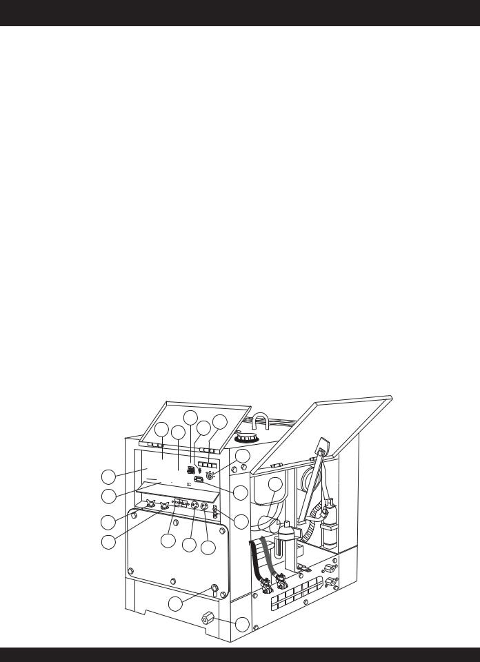
SDW-225SS — CONTROLS AND INDICATORS
17.Fuel Drain Plug – Remove this plug to drain fuel from the fuel tank.
18.Frame Ground Lug – Connect a ground strap between this lug and a ground rod. Make sure that the ground rod is inserted deep into the ground to provide a good earth ground. Consult with local Electrical and Safety Codes for proper connection and depth of ground rod.
19.Oil Filter – Provides oil filtering for the engine.
20.Hour Meter – Indicates number of hours machine has been in use or hours engine was run.
21.Current Control (CC) Adjustment Knob – Use this control to adjust the welding current between 50 to 225 amps.This function will not work in the CV mode.
22.Voltage Control (CV) Adjustment Knob – Use this control to adjust the welding voltage between 15 to 28 V. This function will not work in the CC mode.
23.Welding Type (Wire/Stick) Selector Switch (CV/CC) –
Turn this selector switch toeither CV or CC for welding. DO NOT turn this switch under load.
24.Current Range Selector Switch (CC) – Turn this selector switch to either low or high for welding. DO NOT turn this switch under load.
25.Main Circuit Breaker – This 2-pole circuit breaker provides circuit protection (250V @25 amps) for the Electric Parts Assembly.
26.Circuit Protector Circuit Breaker – This single pole circuit breaker provides circuit protection (120V @20 amps) for the G.F.C.I receptacle.
21 24 25 27 28
27.Idle Control Switch – Regulates the engine speed when the generator is under load.
28.Warning Lamp Display – Includes the following lamps.
zLow Oil Pressure Lamp - lights to indicate that the engine pressure has fallen below acceptable level.
zHighWaterTemperature Lamp - lights to indicate that the water temperature has exceeded 239°F.
zElectrical System Lamp - lights when the electrical system is not charging properly.
zPre-heat Lamp- when the key switch is set to the pre-heat position, this lamp turns on.When the lamp turns off, the key switch can be turned to the start
29.IgnitipositionSwitch. – With key inserted, turn clockwise to start engine.
30.Positive Welding Output Terminal – Connect the welding cable to this terminal. Select the appropriate polarities according to the application.See Table 7.
31.Negative Welding Output Terminal – Connect the negative cable of the welding source to this terminal. Select the appropriate polarities according to the application. See Table 7.
32.Receptacle G.F.C.I.– This receptacle provides 120 volts output at 20 amps.
33.Receptacle – Provides 120 volts output at 25 amps.
34.Receptacle – Provides 120/240 volts output at 25 amps.
23
22
WHISPERWELD |
|
AC CIRCUIT |
|
BREAKER |
|
ON |
|
STOP |
RUN |
HEAT |
|
OFF |
|
IDLE CONTROL |
|
START
00000 |
STARTER SWITCH |
|
|
HOUR METER |
|

 MQ POWER
SDW-225SS
29
20
19
30 |
|
|
26 |
31 |
32 |
33 |
34 |
|
|
MQ WELDER
POWER/ GENERATOR
18
17
Figure 3. SDW-225SS Components 2
PAGE 18 —SDW-225SS WELDER/GENERATOR— OPERATION & PARTS MANUAL — REV. # 2 (10/07/05)

SDW-225SS —TRAILER-10 MAINTENANCE
The SDW-225SS welder/generator can be mounted on a Trailer-10.
Trailer Maintenance
This section is intended to provide the user with service and maintenance information for the Trailer-10.
Periodic inspection of the trailer will ensure safe towing of the generator and will prevent personal injury and damage to the equipment.
The definitions below describe some of the major components of aTrailer-10 that would be used with the SDW-225SS welder/ generator.
1.GVWR- Gross Vehicle Weight Rating (GVWR) is the maximum number of pounds the trailer can carry.
2.Frame Length - Measurement is from the ball hitch to the rear bumper (reflector).
3.Frame Width - Measurement is from fender to fender.
4.Jack Stand - Trailer support device with maximum pound requirement from the tongue of the trailer.
5.Coupler - Type of hitch used on the trailer for towing.
6.Tire Size - Indicates the diameter of the tire in inches (10,12,14, etc.), and the width in millimeters
(175,185,205, etc.). The tire diameter must match the diameter of the tire rim.
9.Tire Ply - The tire ply (layers) number is rated in letters;
2-ply,4-ply,6-ply, etc.
10.Wheel Hub - The wheel hub is connected to the trailer’s axle.
11.Tire Rim - Tires mounted on a tire rim. The tire rim must match the size of the tire.
12.Lug Nuts - Used to secure the wheel to the wheel hub. Always use a torque wrench to tighten down the lug nuts. See Table 5 and Figure 5 for lug nut tightening and sequence.
13.Axle - Indicates the maximum weight the axle can support in pounds, and the diameter of the axle expressed in inches.
14.Suspension - Protects the trailer chassis from shocks transmitted through the wheels. Types of suspension used are leaf, Q-flex, and air ride.
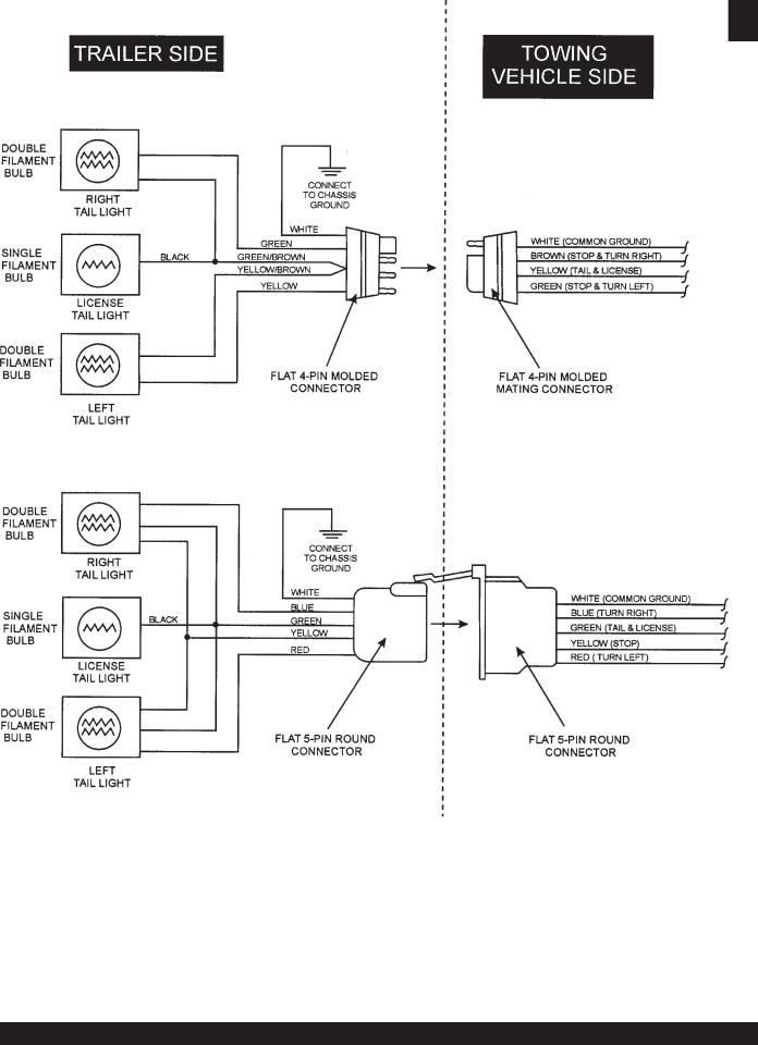
15.Electrical - Electrical connectors (looms) are provided with the trailer so the brake lights and turn signals can be connected to the towing vehicle.
Table 2. Trailer-10 Specifications
GVWR |
1900 lbs |
||
|
|
||
Frame Length |
96 inches |
||
|
|
||
Frame Width |
50 inches |
||
|
|
||
Jack Stand |
800 lbs |
||
Full Tilt Wheel |
|||
|
|||
|
|
||
Coupler |
2-inch Ball Class 2 Adjustable |
||
|
|
||
Tires |
175-13C |
||
|
|
||
Wheels |
13 x 4.5 inches |
||
|
|
||
Axle |
2200# 2X2 |
||
|
|
|
|
Hubs |
5 |
Lug |
|
|
|
|
|
Suspension |
3 |
Leaf |
|
|
|
|
|
Electrical |
4 |
Pole Flat |
|
|
|
|
|
SDW-225SS WELDER/GENERATOR — OPERATION & PARTS MANUAL — REV. #2 (10/07/05) — PAGE 19

SDW-225SS —TRAILER-10 MAINTENANCE
Tires/Wheels/Lug Nuts
Tires and wheels are a very important and critical components of the trailer. When specifying or replacing the trailer wheels it is important the wheels, tires, and axle are properly matched.
CAUTION - EYESIGHT HAZARD
ALWAYS wear safety glasses when removing or installing force fitted parts. Failure to comply may result in serious injury.
CAUTION - REPAIRINGTRAILERWHEELS
DO NOT attempt to repair or modify a wheel. DO NOT install in inner tube to correct a leak through the rim. If the rim is cracked, the air pressure in the inner
tube may cause pieces of the rim to explode (break off) with great force and cause serious eye or bodily injury.
Tire Wear/Inflation
Tire inflation pressure is the most important factor in tire life. Pressure should be checked cold before operation DO NOT bleed air from tires when they are hot!. Check inflation pressure weekly during use to insure the maximum tire life and tread wear.
Table 3 (Tire Wear Troubleshooting) will help pinpoint the causes and solutions of tire wear problems.
Suspension
The leaf suspension springs and associated components (Figure 4) should be visually inspected every 6,000 miles for signs of excessive wear, elongation of bolt holes, and loosening of fasteners. Replace all damaged parts (suspension) immediately. Torqued suspension components as detailed in Table 4.
Figure 4. Major Suspension Components
Table 4. Suspension Torque Requirements
Item |
Torque (Ft.-Lbs.) |
|
|
|
|
3/8" U-BOLT |
MIN-30 MAX-35 |
|
|
|
|
7/16" U-BOLT |
MIN-45 MAX-60 |
|
|
|
|
1/2" U-BOLT |
MIN-45 MAX-60 |
|
|
|
|
SHACKLE BOLT |
SNUG FIT ONLY. PARTS MUST ROTATE FREELY. |
|
LOCKING NUTS OR COTTER PINS ARE PROVIDED |
||
SPRING EYE BOLT |
||
TO RETAIN NUT-BOLT ASSEMBLY. |
||
|
||
|
|
|
SHOULDER TYPE |
MIN-30 MAX-50 |
|
SHACKLE BOLT |
||
|
||
|
|
PAGE 20 —SDW-225SS WELDER/GENERATOR— OPERATION & PARTS MANUAL — REV. # 2 (10/07/05)
SDW-225SS —TRAILER-10 MAINTENANCE
Lug NutTorque Requirements
It is extremely important to apply and maintain proper wheel mounting torque on the trailer. Be sure to use only the fasteners matched to the cone angle of the wheel. Proper procedure for attachment of the wheels is as follows:
1.Start all wheel lug nuts by hand.
2.Torque all lug nuts in sequence (see Figure 5). DO NOT torque the wheel lug nuts all the way down.Tighten each lug nut in 3 separate passes as defined by Table 5.
3.After first road use, re-torque all lug nuts in sequence.
Check all wheel lug nuts periodically.
Table 5. Tire Torque Requirements
Wheel Size |
First Pass |
Second Pass |
Third Pass |
|
FT-LBS |
FT-LBS |
FT-LBS |
|
|
|
|
12" |
20-25 |
35-40 |
50-65 |
|
|
|
|
13" |
20-25 |
35-40 |
50-65 |
|
|
|
|
14" |
20-25 |
50-60 |
90-120 |
|
|
|
|
15" |
20-25 |
50-60 |
90-120 |
|
|
|
|
16" |
20-25 |
50-60 |
90-120 |
|
|
|
|
NOTE |
NEVER use an pneumatic air |
|
gun to tighten wheel lug nuts. |
Figure 5. Wheel Lug Nuts
Tightening Sequence
SDW-225SS WELDER/GENERATOR — OPERATION & PARTS MANUAL — REV. #2 (10/07/05) — PAGE 21
SDW-225SS —TRAILER-10 MAINTENANCE
Figure 6. Trailer/Towing Vehicle Wiring Diagram
PAGE 22 —SDW-225SS WELDER/GENERATOR— OPERATION & PARTS MANUAL — REV. # 2 (10/07/05)
SDW-225SS —TRAILER-10 MAINTENANCE
Towing Safety Precautions
 CAUTION
Check with your local county or state towing safety regulations before towing your generator.
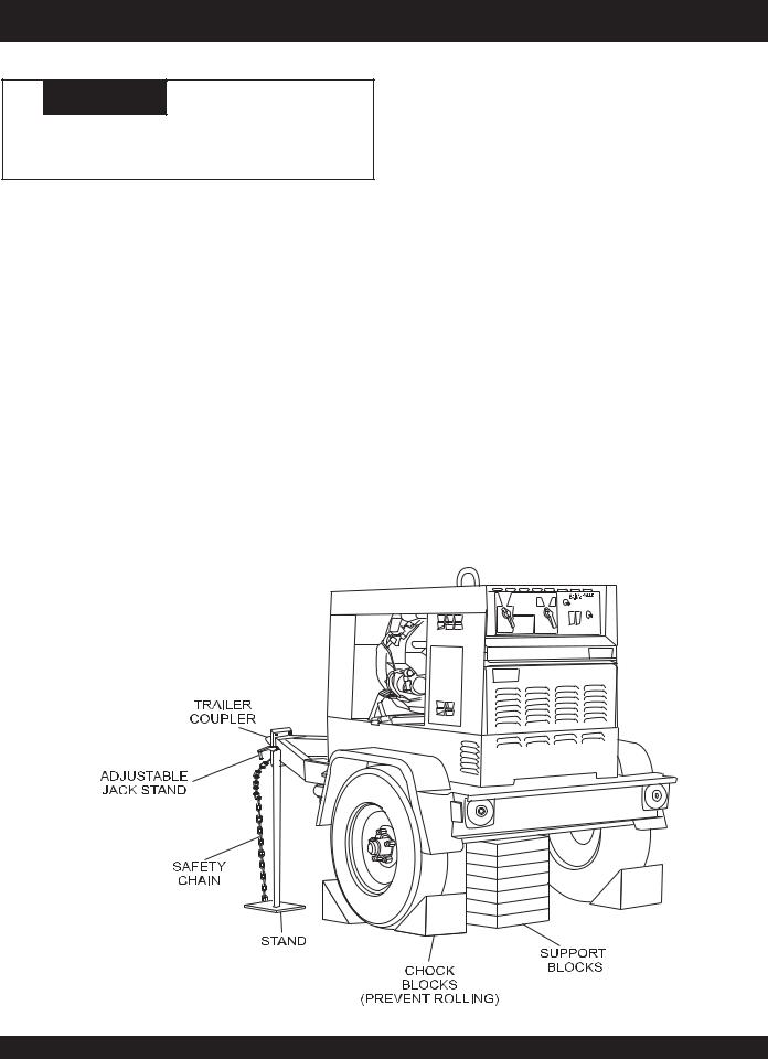
To reduce the possibility of an accident while transporting the generator on public roads, always make sure the trailer
(Figure 7) that supports the generator and the towing vehicle are in good operating condition and both units are mechanically sound.
The following list of suggestions should be used when towing your generator:
■Make sure the hitch and coupling of the towing vehicle are rated equal to, or greater than the trailer "gross vehicle weight rating" (GVWR).
■ALWAYS inspect the hitch and coupling for wear.NEVER tow a trailer with defective hitches, couplings, chains etc.
■Check the tire air pressure on both towing vehicle and trailer. Also check the tire tread wear on both vehicles.
■ALWAYS make sure the trailer is equipped with a "Safety Chain".
■ALWAYS attach trailer’s safety chain to bumper of towing vehicle.
■ALWAYS make sure the vehicle and trailer directional, backup, brake, and trailer lights are connected and working properly.
■The maximum speed for highway towing is 55 MPH unless posted otherwise. Recommended off-road towing is not to exceed 15 MPH or less depending on type of terrain. Refer to state or local towing regulations.
■Place chocked blocks underneath wheel to prevent rolling, while parked.
■Place support blocks underneath the trailer’s bumper to prevent tipping, while parked.
■Insert locking pin to lock wheel stand in place, while parked. Use the trailer’s adjustable jack stand to adjust the height of the trailer.
■Avoid sudden stops and starts. This can cause skidding, or jackknifing. Smooth, gradual starts and stops will improve gas mileage of towing vehicle.
■Avoid sharp turns to prevent rolling.
■Remove or fold up wheel stand when transporting.
■DO NOT transport generator with fuel in tank.
Figure 7. Generator with Trailer
SDW-225SS WELDER/GENERATOR — OPERATION & PARTS MANUAL — REV. #2 (10/07/05) — PAGE 23

SDW-225SS — WKT225A WHEEL KIT ASSEMBLY
The SDW-225SS welder/generator can be mounted on a WKT225A Wheel Kit. .
Below are assembly Instructions for the WKT225 Wheek Kit.
Tools:
■Flashlight
■Ratchet Set with 3/4", 9/16" sockets
■Adjustable Wrench or 3/4", 9/16", 10mm open end wrenches
■Lifting Device of adequate capacity
Procedure:
1.Assemble the Caster wheels (Figure 8) - Place the Caster mount plate on the adjustment plate so the bolt holes line up. Insert screws through the holes in the two plates and push the caster wheel onto the screws. Loosely secure the caster wheel to the adjustment plate using the provided nuts to allow for adjustment when attaching the caster wheels to the cabinet. Repeat for the other side of the caster wheel assembly.
2.Assemble the stationary axle (Figure 9) - Push the roll pin through the inner axle hole. Slide a flat washer onto the axle shaft, then put the wheel on the axle. Push the wheel flat against the washer and roll pin and slide a flat washer against the wheel. Then insert the cotter pin through the outer axle hole to secure the wheel on the axle.
Figure 9. Stationary Axle Assembly
3.Remove side covers to provide access to the interior of the cabinet. (Figure 10).
Figure 8. Caster Wheel Assembly
 WARNING
DO NOT attempt to manually lift your generator/welder. Use a lifting device that is rated to handle the full weight of the equipment. DO NOT stand under the machine while it is suspended in air.
Figure 10. Removing Access Covers
 CAUTION
Two people might be required to perform this installation procedure safely. One person should support the axle for another person to prevent the axle from dropping.
PAGE 24 —SDW-225SS WELDER/GENERATOR— OPERATION & PARTS MANUAL — REV. # 2 (10/07/05)
SDW-225SS — WKT225A WHEEL KIT ASSEMBLY
4.Insert a lifting strap through the lifting eye on top of the machine and raise the generator/welder off the ground using a lifting device of adequate capacity (Figure 11). The generator/welder can be suspended in air while installing the wheel kit or can be set down on an object which can support the weight of the machine. Ensure the bottom of the cabinet has enough clearance to install the wheel kit.
Figure 11. Lifting Equipment
5.Locate the four bolt holes on the underside of the cabinet near the front and rear of the machine. Reach into the cabinet and place a bolt and washer through the cabinet floor through each hole (Figure 12). A flashlight might be necessary to find the bolt holes in the cabinet floor.
Figure 13. Securing Stationary Axle and
Caster Wheel Assembly to Cabinet
7.Center the caster wheel assembly underneath the machine. Lift the caster wheels up so the bolts in the cabinet floor pass through the bolt holes on the caster wheel frame. Place a washer on the bolt under the castor wheel frame and secure the castor wheels to the cabinet with a nut (Figure 13).
8.Lower the machine onto the ground and remove the lifting strap from the lifting eye. The machine should roll freely.
9.Near the top of the cabinet on the rear(control panel side) of the machine, remove the two bolts from the cabinet wall. Attach the handle to the cabinet wall by inserting a bolt, lock washer, and flat washer through the bottom two bolt holes on the handle into the cabinet (Figure 14).
Repeat on the other side of the cabinet.
Figure 12. Inserting Bolts/Washers
6.With the stationary axle facing front, lift the axle up so the bolts in the cabinet floor pass through the bolt holes on the axle. Place a washer on the bolt under the axle and secure the axle to the cabinet with a nut (Figure 13).
 CAUTION
Lock the caster wheels in place with the attached brake lever when the generator/welder is not being moved to prevent the machine from unintentional rolling while in
use.
Figure 14. Attaching Handles to Cabinet
SDW-225SS WELDER/GENERATOR — OPERATION & PARTS MANUAL — REV. #2 (10/07/05) — PAGE 25
Outdoor Installation
Install the generator in a location where it will not be exposed to rain or sunshine. Make sure that the welder/generator is on secure level ground so that it cannot slide or shift around. Also install the generator in a manner so that the exhaust will not be discharged in the direction of nearby homes.
The installation site must be relatively free from moisture and dust. All electrical equipment should be protected from excessive moisture. Failure to do will result in deterioration of the insulation and will result in short circuits and grounding.
Foreign materials such as dust, sand, lint and abrasive materials have a tendency to cause excessive wear, not only to the engine parts, but also to the alternator parts.
 CAUTION
Pay close attention to ventilation when operating the generator inside tunnels and caves.The engine exhaust contains noxious elements.
Indoor Installation
Exhaust gases from diesel engines are extremely poisonous.
Whenever an engine is installed indoors the exhaust fumes must be vented to the outside.
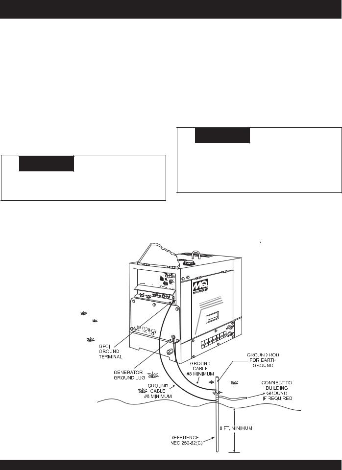
Figure 15. Generator Grounding
SDW-225SS — INSTALLATION
The engine should be installed at least two feet from any outside wall. Using an exhaust pipe which is too long or too small can cause excessive back pressure which will cause the engine to heat excessively and possibly burn the valves.
Eliminate the danger of deadly carbon monoxide gas. Remember that exhaust fumes from any diesel engine are very poisonous if discharged in a closed room, but harmless if allowed to mix with the outside air. If the generator is installed indoors, you must make provisions for venting the engine exhaust to the outside of the building.
 CAUTION
An electric shock is apt to happen when generators are used. Pay close attention to handling when operating generator and always use rubber boots and gloves to insulate the body from a short circuit.
Connecting the Ground
The generator ground lug and the GFCI ground terminal should always be used to connect the generator to a suitable ground.
Thegroundcableshouldbe#8sizewireminimum.SeeFigure15.
PAGE 26 —SDW-225SS WELDER/GENERATOR— OPERATION & PARTS MANUAL — REV. # 2 (10/07/05)

General Inspection Prior to Operation
The SDW-225SS utilizes a generator that has been thoroughly inspected and accepted prior to shipment from the factory. However, be sure to check for damaged parts or components, or loose nuts and bolts, which could have occurred in transit.
Circuit Breakers
To protect the welder/generator from an overload, a 2-pole, 25 amp, main circuit breaker is provided. In addition a single pole, 20 amp breaker is provided for the G.F.C.I. receptacle. Make sure to switch both circuit breakers to the "OFF" position prior to starting the engine.
SDW-225SS — PRE-SETUP
Extension Cable
When electric power is to be provided to various tools or loads at some distance from the generator, extension cords are normally used. Cables should be sized to allow for distance in length and amperage so that the voltage drop between the generator and point of use (load) is held to a minimum.Use the cable selection chart (Table 6) as a guide for selecting proper cable size.
Table 6. Cable Selection (60 Hz, Single Phase Operation)
Current in |
Load In Watts |
|
|
Maximum Allowable Cable Length |
|
||||||
|
|
|
|
|
|
|
|
|
|
|
|
At 120 |
At 240 |
|
|
|
|
|
|
|
|
|
|
Amperes |
#10 Wire |
|
#12 Wire |
#14 Wire |
|
#16 Wire |
|||||
|
Volts |
Volts |
|
|
|||||||
|
|
|
|
|
|
|
|
|
|
||
|
|
|
|
|
|
|
|
|
|
||
2.5 |
300 |
600 |
1000 ft. |
|
600 |
ft. |
375 ft. |
|
250 ft. |
||
|
|
|
|
|
|
|
|
|
|
|
|
5 |
600 |
1200 |
500 |
ft. |
|
300 |
ft. |
200 ft. |
|
125 ft. |
|
|
|
|
|
|
|
|
|
|
|
|
|
7.5 |
900 |
1800 |
350 |
ft. |
|
200 |
ft. |
125 ft. |
|
100 ft. |
|
|
|
|
|
|
|
|
|
|
|
||
10 |
1200 |
2400 |
250 |
ft. |
|
150 ft. |
100 ft. |
|
|
||
|
|
|
|
|
|
|
|
|
|
||
15 |
1800 |
3600 |
150 ft. |
|
100 ft. |
65 |
ft. |
|
|
||
|
|
|
|
|
|
|
|
|
|
||
20 |
2400 |
4800 |
125 ft. |
|
75 ft. |
50 |
ft. |
|
|
||
|
|
|
|
|
|
|
|
|
|
||
30 |
3600 |
7200 |
75 ft. |
|
50 ft. |
35 |
ft. |
|
|
||
|
|
|
|
|
|
|
|
|
|
||
CAUTION: Equipment damage can result from low voltage. |
|
|
|
|
|
||||||
|
|
|
|
|
|
|
|
|
|
|
|
SDW-225SS WELDER/GENERATOR — OPERATION & PARTS MANUAL — REV. #2 (10/07/05) — PAGE 27
Lubrication Oil
Fill the engine crankcase with lubricating oil through the filler hole, but do not overfill. Make sure the generator is level.
With the dipstick inserted all the way, but without being screwED into the filler hole, verify that the oil level is maintained between the two notches (Figure 16) on the dipstick. See Table 3 for proper selection of engine oil.
Figure 16. Engine Oil Dipstick
SDW-225SS — PRE-SETUP
Fuel
Fill the fuel tank with clean and fresh diesel fuel. Do not fill the tank beyond capacity.
Pay attention to the fuel tank capacity when replenishing fuel. Refer to the fuel tank capacity listed on page 11 Specification Table 1.
The fuel tank cap must be closed tightly after filling. Handle fuel in a safety container. If the container does not have a spout, use a funnel.
 CAUTION
Never fill the fuel tank while the engine is running or in the dark. Diesel fuel spillage on a hot engine can cause a fire or explosion. If diesel fuel spillage occurs, wipe up the spilled diesel fuel completely to prevent fire hazards.
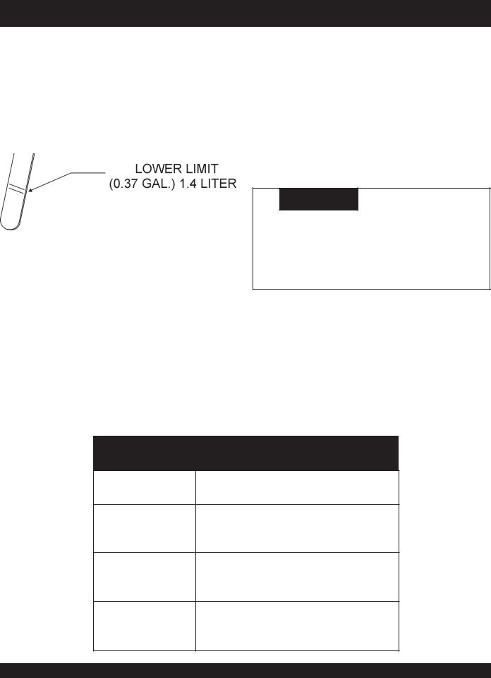
Coolant
Use only potable tap water. If hard water or water with many impurities is used, the inside of the engine and radiator may become coated with deposits and cooling efficiency will be reduced.
An anticorrosion additive added to the water will help prevent deposits and corrosion in the cooling system. See the engine manual for further details.
Table 7. Recommended Motor Oil
Temperature Range |
Type Oil |
Above 77° F
SAE30 or
(25° C)
SAE10W-30
SAE10W-40
32° F ~ 77° F
SAE20 or
(0° C ~ 25°C)
SAE10W-30
SAE10W-40
SAE10 or Below 32° F (0° C) SAE10W-30
SAE10W-40
PAGE 28 —SDW-225SS WELDER/GENERATOR— OPERATION & PARTS MANUAL — REV. # 2 (10/07/05)

 CAUTION
When adding coolant or anti-freeze to the radiator, do not remove the radiator cap until the unit has completely cooled.
Day-to-day addition of coolant or anti-freeze is done from the reserve tank. SeeTable 8.for engine, radiator and reserve tank coolant capacities. Make sure that the coolant level in the reserve tank is always between the "H" and the "L" markings.
Table 8. Coolant Capacity
Engine and Radiator |
0.66 Gal. |
|
|
Reserve Tank |
0.27 Gal. |
|
|
SDW-225SS — PRE-SETUP
Cleaning the Radiator
The radiator may overheat if the fins become overloaded with dust or debris. Periodically clean the radiator fins with compressed air. Cleaning inside the machine is dangerous, so clean only with the engine turned off.
Fan Belt Tension
A slack fan belt may contribute to overheating, or to insufficient charging of the battery. Inspect and adjust it in accordance with the KUBOTA engine manual.
The fan belt tension is proper if the fan belt (Figure17) bends
7 to 9 mm (0.28to 0.35 in.) when depressed with the thumb as shown in Figure 16 below.
Operation in Freezing Weather
When operating in freezing weather, be certain that the proper amount of antifreeze has been added.See Table 9. for antifreeze operating temperatures.
Table 9. Anti-Freeze Operating Temperatures
Vol % |
Freezing Point |
Boiling Point |
||
|
|
|
|
|
Anti-Freeze |
°C |
°F |
°C |
°F |
|
||||
|
|
|
|
|
40 |
-24 |
-12 |
106 |
222 |
|
|
|
|
|
50 |
-37 |
-34 |
108 |
226 |
|
|
|
|
|
When the anti-freeze is mixed with water, the antifreeze mixing ratio must be less than 50%.
Figure 17. Fan Belt Tension
Air Cleaner
Periodic cleaning/replacement is necessary. Inspect it in accordance with the engine manual.
Battery
This unit is of negative ground. DO NOT connect in reverse.
Always maintain battery fluid level between the specified marks. Battery life will be shortened, if the fluid level is not properly maintained. Add only distilled water when replenishment is necessary.
The battery is sufficiently charged if the specific gravity of the battery fluid is 1.28 (at 68° F). If the specific gravity should fall to 1.245 or lower, it indicates that the battery is dead and needs to be recharged or replaced.
Check to see whether the battery cables are loose. Poor contact may result in poor starting or malfunctions, always keep the terminals firmly tightened. Coating the terminals with a thin film of grease will help to inhibit corrosion.
The battery gradually deteriorates over time. The actual life span will vary according to operating conditions, but generally a battery two years or older should be replaced.
SDW-225SS WELDER/GENERATOR — OPERATION & PARTS MANUAL — REV. #2 (10/07/05) — PAGE 29

 CAUTION
When using a combination of dual receptacles, total load should not exceed the rated capacity of the generator set.
Power Outlets
The generator has the following single-phase 60 Hz, 120/
240 volt receptacles.
zSingle Phase
One Duplex NEMA (GFCI) 5-20R (120V, 20 Amp)
One Twist Lock NEMA L14-30R (120/240V, 30 Amp)
One Twist Lock NEMA L5-30R (120V, 30 Amp)
Main Circuit Breaker (2-Pole)
This 2-pole, 25 amp breaker protects the generator from short circuiting or overloading from the 60 Hz single-phase load.
GFCI Protection Breaker (Single-Pole)
This single-pole, 20 amp breaker protects the GFCI receptacle from short circuiting or overloading.
Warning Indicator Lights
The generator has the following warning indicator lights:
Oil Pressure Light
If the oil pressure drops suddenly, the oil pressure light will go on, and the generator will shut down.
SDW-225SS — INSTRUMENTATION
Charge Light
The charge light will go on when the battery fails to charge, and the generator will shut down.
WaterTemperature Light
The water temperature light will go on if the temperature rises to an abnormally high level, and the generator will shut down.
Idle Control Switch
The generator is provided with an automatic idle control device for noise suppression and reduced fuel consumption. The automatic idle control automatically engages under a no-load condition. With the automatic idle control switched to "ON", the engine revolutions will automatically drop to about 2600 rpm (low-speed operation) within 3 seconds after the load stops. When the operation is resumed, the engine speed is automatically increased to about 3600 rpm (high speed operation) as soon as the load is connected.
Fuel Gauge
The fuel gauge is located on top of the generator's enclosure and allows easy monitoring of the fuel level.
GFCI Receptacle
Before connecting a load to the generator's GFCI receptacle, push the "Test Button" on the front of receptacle before connecting the load, to confirm that the receptacle is functioning correctly.
PAGE 30 —SDW-225SS WELDER/GENERATOR— OPERATION & PARTS MANUAL — REV. # 2 (10/07/05)
 Loading...