


Operation and Parts Manual
MODEL ga6Hr/ga6Hrs
portable generatorS
(HONDA GX340RT2EDN2/GX340RT2EDE2
GASOLINE ENGINES)
Revision #0 (08/12/14)
To find the latest revision of this publication, visit our website at: www.multiquip.com
THIS MANUAL MUST ACCOMPANY THE EQUIPMENT AT ALL TIMES.
PROPOSITION 65/START FIRES WARNINGS
Operation of this equipment may create sparks that can start fires around dry vegetation. A spark arrestor may be required. The operator should contact local fire agencies for laws or regulations relating to fire prevention requirements.
page 2 — GA6HR/GA6HRS 60 hz gENERATOR• operation and parts manual — rev. #0 (08/12/14)
Table of Contents
GA6HR/GA6HRS 60 Hz |
|
Portable Generator |
|
Proposition 65/Start Fires Warnings........................ |
2 |
Table Of Contents.................................................... |
3 |
Nameplate/Safety Information.................................. |
4 |
Parts Ordering Procedures...................................... |
5 |
Safety Information.................................................... |
6 |
Safety Information............................................... |
7-11 |
Specifications (Generator)..................................... |
12 |
Specifications (Engine).......................................... |
13 |
Dimensions............................................................ |
14 |
Installation......................................................... |
16-17 |
General Information............................................... |
18 |
Components (Generator).................................. |
19-21 |
Inspection/Setup............................................... |
22-23 |
Operation.......................................................... |
24-26 |
Shutdown............................................................... |
27 |
Preparation For Long Term Storage....................... |
28 |
Maintenance...................................................... |
29-33 |
Generator Wiring Diagram (GA6HR) ..................... |
34 |
Generator Wiring Digram (GA6HRS) .................... |
35 |
Troubleshooting (Engine)....................................... |
36 |
Troubleshooting (Engine)....................................... |
37 |
Troubleshooting (Generator).................................. |
38 |
Explanation of Code in Remarks Column.............. |
40 |
Suggested Spare Parts.......................................... |
41 |
Component Drawings |
|
Nameplate And Decals Assembly..................... |
42-43 |
Generator Assembly......................................... |
44-45 |
Control Box Assembly (GA6HR)....................... |
46-47 |
Control Box Assembly (GA6HRS)..................... |
48-49 |
Pipe Frame Assembly....................................... |
50-51 |
Battery Assembly (GA6HRS)............................ |
52-53 |
Muffler Assembly............................................... |
54-55 |
Wheel Kit Assembly.......................................... |
56-57 |
Honda GX340RT2EDE2/EDN2
Gasoline Engine
Air Cleaner Assembly........................................ |
58-59 |
Camshaft Assembly.......................................... |
60-61 |
Carburetor Assembly......................................... |
62-63 |
Control Assembly.............................................. |
64-65 |
Crankcase Cover Assembly............................... |
66-67 |
Crankshaft Assembly........................................ |
68-69 |
Cylinder Barrel Assembly.................................. |
70-71 |
Cylinder Head Assembly................................... |
72-73 |
Fan Cover Assembly......................................... |
74-75 |
Flywheel Assembly........................................... |
76-77 |
Ignition Coil Assembly....................................... |
78-79 |
Piston Assembly................................................ |
80-81 |
Recoil Starter Assembly.................................... |
82-83 |
Starter Motor Assembly (Electric Start)............. |
84-85 |
Solenoid Assembly............................................ |
86-87 |
Engine Decals Assembly.................................. |
88-89 |
Terms and Conditions of Sale — Parts.................. |
90 |
 NOTICE
Specifications and part numbers are subject to change without notice.
GA6HR/6HRS 60 hz GENERATOR • operation and parts manual — rev. #0 (08/12/14) — page 3
nameplate/safety information
nAMEPLATE AND sAFETY lABELS
Safety labels are attached to the generator as shown in Figure 1. Keep these safety labels clean at all times. When the safety labels become worn or damaged, contact your nearest dealer or the Multiquip Parts Dept.
|
GA-6HR |
|
|
V 120 |
0N |
|
|
|
|
120 |
OFF |
|
|
|
|
AC VOLTMETER |
IDLE |
|
|
|
|
CONTROL |
|
|
|
|
|
120V |
|
|
|
AC CIRCUIT BREAKER |
|
||
120V |
QUARTZ |
|
GFCI PROTECTED |
240/120V |
|
120V |
|
|
FULL POWER |
|
|
20A |
20A |
120V |
120V |
SWITCH |
120/240V |
|
20A |
|
30A |
|
30A |
Figure 1. Nameplate And Safety Decals
WARNING |
|
DANGER |
|
CAUTION |
|
|
OPERATE AT |
||||
To avoid injury, |
|
Do not touch output terminals or |
3600 RPM ONLY |
||
|
internal wiring while unit is operating. |
||||
you MUST read |
|
S-4985 Turn off power before servicing. |
(FULL THROTTLE) |
||
and understand |
ELECTRICAL |
Only qualified personnel should |
DAMAGE MAY RESULT IF |
||
operator’s manual |
SHOCK |
install, use or service this |
OPERATED AT LOWER SPEEDS |
||
HAZARD |
equipment. |
||||
before using this |
|
|
|
|
|
machine. |
|
WARNING |
WARNING |
||
This machine to |
|
||||
be operated by |
|
Only operate machine in well ventilated |
B e f o r e c o n n e c t i n g t h i s |
||
qualified |
|
g e n e r a t o r |
t o a n y b u i l d i n g ’ s |
||
|
areas. |
e l e c t r i c a l |
s y s t e m , a l i c e n s e d |
||
personnel only. |
|
DO NOT inhale exhaust gases. |
e l e c t r i c i a n m u s t i n s t a l l a n |
||
Ask for training |
|
S-4984 Only qualified personnel shouldi s o l a t i o n ( t r a n s f e r ) s w i t c h . |
|||
as needed. |
DANGEROUS |
install,Only qualifieduse personnelor serviceshouldthis |
S e r i o u s i n j u r y |
o r d e a t h m a y |
|
install, use or service this |
r e s u l t w i t h o u t |
t h i s t r a n s f e r |
|||
|
GAS |
equipment.equipment. |
s w i t c h . |
|
|
|
|
|
|
|
A91110010 |
NOTICE
For safety label part numbers, reference the parts section of this manual..
MODEL
SERIAL NO.
DANGER
Using a generator indoors CAN KILL YOU IN MINUTES.
Utilser un générateur à l’ intérieur VOUS TUERA EN QUELQÙES MINUTES.
Exhaust contains carbon monoxide, a poison gas you cannot see or smell. Les gaz d’ échappement contiennent du monoxyde de carbon, un gaz toxique invisible et inodore.
NEVER use in enclosed or partially |
ONLY use outdoors and away from |
|
open windows, doors, and vents. |
||
enclosed areas. |
||
Utilisation INTERDITE dans un |
Utilisation UNIQUEMENT à l’ extér leur |
|
portes et trous d’ aération |
||
espace clos ou partiellement clos. |
||
|
||
|
A90400001 |
Operation of this equipment may create sparks that can start fires around dry vegetation.
A spark arrestor may be required. The operator should contact local fire agencies for laws or regulations
relating to fire prevention requirements.
M 90420000
DANGER
THE POSSIBILITY EXISTS OF ELECTROCUTION IF
GENERATOR/WELDER IS NOT PROPERLY GROUNDED.
ALWAYS CONNECT EARTH GROUND (GROUND
ROD) TO GENERATOR GROUND POINT.
6000
GROUND
SCREW
GROUND
CABLE
#8 MINIMUM
GROUND ROD
FOR EARTH
GROUNDCONNECT TO
BUILDING
GROUND
IF REQUIRED
FOR FURTHER GROUNDING |
8 FT. MINIMUM |
INSTRUCTIONS, READ MANUAL |
|
REFERENCE
NEC 250-52(C)
D9531100104
page 4 — GA6HR/GA6HRS 60 hz gENERATOR• operation and parts manual — rev. #0 (08/12/14)
www.multiquip.com
parts ordering procedures
Ordering parts has never been easier!
Choose from three easy options:
Effective: January 1st, 2006
Best deal! Order via internet (dealers Only):
Order parts on-line using Multiquip’s SmartEquip website!
■View Parts Diagrams
■Order Parts
■Print Specifi cation Information
Goto www.multiquip.com and click on
Order  Parts to log in and save!
If you have an MQ Account, to obtain a Username and Password, E-mail us at: parts@multiquip. com.
To obtain an MQ Account, contact your
District Sales Manager for more information.
Use the internet and qualify for a 5% discount on Standard orders for all orders which include complete part numbers.*
Note: Discounts Are Subject To Change
|
|
|
|
Order via Fax (dealers Only): |
|
Fax your order in and qualify for a 2% discount |
|
|
|
|
|
|
|
|
|||
|
|
|
|
All customers are welcome to order parts via Fax. |
|
on Standard orders for all orders which include |
||
|
|
|
|
|
||||
|
|
|
|
domestic (us) Customers dial: |
|
complete part numbers.* |
||
|
|
|
|
1-800-6-PARTS-7 (800-672-7877) |
|
|
|
|
|
Note: Discounts Are Subject To Change |
|||||||
|
|
|
|
|
||||
|
|
|
|
|
|
|||
|
|
|
|
|
|
|
|
|
|
|
|
|
|
|
|
Order via phone: |
domestic (us) dealers Call: |
||||||||
|
|
|
|
|
|
|
||||||||||
|
|
|
|
|
|
|||||||||||
|
|
|
|
|
|
|
|
|
|
|
|
|
|
1-800-427-1244 |
|
|
|
|
|
|
|
|
|
|
|
|
|
|
|
|
|
|
|
|
|
|
|
|
|
|
|
|
|
|
|
|
|
|
|
|
|
|
|
Non-dealer Customers: |
|
|
|
|
|
|
|
||||||
|
|
|
International Customers should contact |
|||||||||||||
|
|
|
Contact your local Multiquip Dealer for |
|||||||||||||
|
|
|
their local Multiquip Representatives for |
|||||||||||||
|
|
|
parts or call 800-427-1244 for help in |
|||||||||||||
|
|
|
Parts Ordering information. |
|||||||||||||
|
|
|
locating a dealer near you. |
|||||||||||||
|
|
|
|
|
|
|||||||||||
|
|
|
|
|
|
|
|
|
|
|
|
|
|
|
|
|
When ordering parts, please supply:
dealer Account Number
dealer Name and Address
shipping Address (if different than billing address)
Return Fax Number
Applicable model Number
Quantity, part Number and description of Each part
specify preferred method of shipment:
UPS/Fed Ex |
DHL |
Priority One |
Truck |
Ground
Next Day
Second/Third Day

 NOTICE
All orders are treated as Standard Orders and will ship the same day if received prior to 3PM PST.
WE ACCEpT All mAJOR CREdiT CARds!
GA6HR/6HRS 60 hz GENERATOR • operation and parts manual — rev. #0 (08/12/14) — page 5
Safety Information
Do not operate or service the equipment before reading the entire manual. Safety precautions should be followed at all times when operating this equipment. Failure to read and understand the safety messages and operating instructions could result in injury to yourself and others.
sAFETY mEssAgEs
The four safety messages shown below will inform you about potential hazards that could injure you or others.The safety messages specifi cally address the level of exposure to the operator and are preceded by one of four words: dANgER,WARNiNg, CAuTiON or NOTiCE.
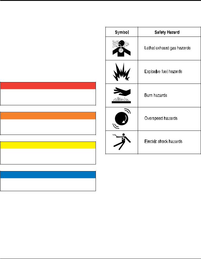
sAFETY sYmBOls
 dANgER
Indicates a hazardous situation which, if not avoided,
Will result in dEATh or sERiOus iNJuRY.
 WARNiNg
Indicates a hazardous situation which, if not avoided,
COuld result in dEATh or sERiOus iNJuRY.
 CAuTiON
Indicates a hazardous situation which, if not avoided,
COuld result in miNOR or mOdERATE iNJuRY.
NOTICE
Addresses practices not related to personal injury.
Potential hazards associated with the operation of this equipment will be referenced with hazard symbols which may appear throughout this manual in conjunction with safety messages.
page 6 — GA6HR/GA6HRS 60 hz gENERATOR• operation and parts manual — rev. #0 (08/12/14)
Safety Information
gENERAl sAFETY
 CAuTiON
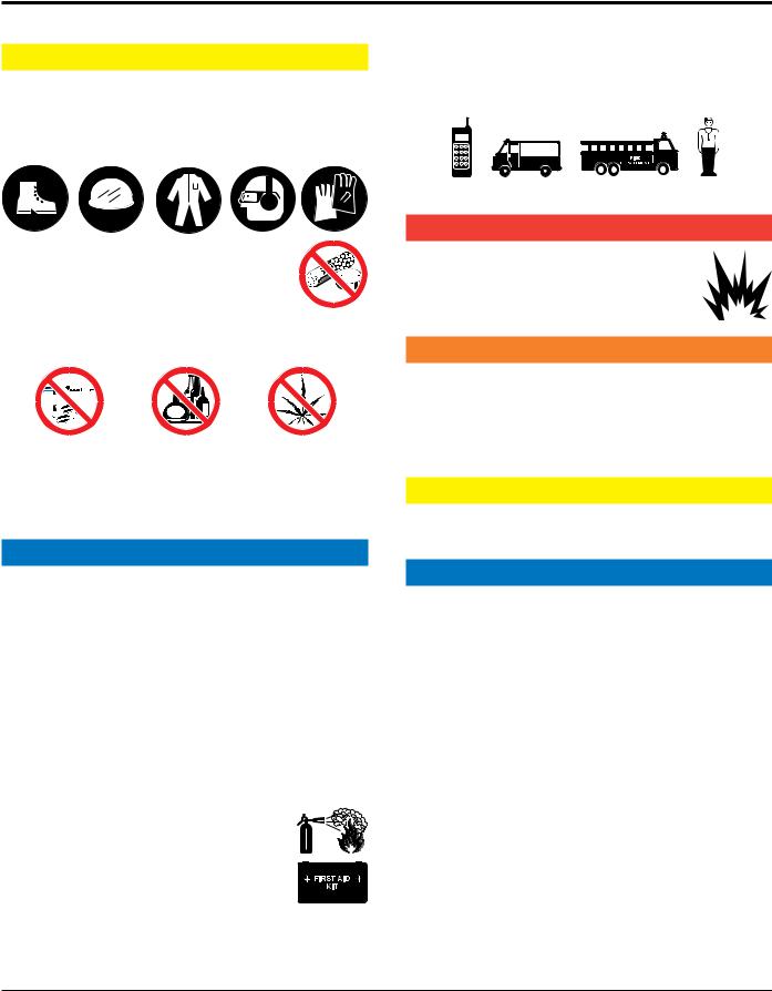
NEvER operate this equipment without proper protective clothing, shatterproof glasses, respiratory protection, hearing protection, steel-toed boots and other protective devices required by the job or city and state regulations.
NEvER operate this equipment when not feeling well due to fatigue, illness or when under medication.
NEvER operate this equipment under the infl uence of drugs or alcohol.
AlWAYs check the equipment for loosened threads or bolts before starting.
dO NOT use the equipment for any purpose other than its intended purposes or applications.
NOTICE
This equipment should only be operated by trained and qualifi ed personnel 18 years of age and older.
Whenever necessary, replace nameplate, operation and safety decals when they become diffi cult read.
Manufacturer does not assume responsibility for any accident due to equipment modifi cations. Unauthorized equipment modifi cation will void all warranties.
NEvER use accessories or attachments that are not recommended by Multiquip for this equipment. Damage to the equipment and/or injury to user may result.
AlWAYs know the location of the nearest fi re extinguisher.
AlWAYs know the location of the nearest fi rst aid kit.
AlWAYs know the location of the nearest phone or keep a phone on the job site.Also, know the phone numbers of the nearest ambulance,doctor and fi re department.
This information will be invaluable in the case of an emergency.
gENERATOR sAFETY
 dANgER
NEvERoperate the equipment in an explosive atmosphere or near combustible materials.An explosion or fi re could result causing severe bodily harm or even death.
 WARNiNg
NEvER disconnect any emergency or safety devices.
These devices are intended for operator safety. Disconnection of these devices can cause severe injury, bodily harm or even death. Disconnection of any of these devices will void all warranties.
 CAuTiON
NEvER lubricate components or attempt service on a running machine.
NOTICE
AlWAYs ensure generator is on level ground before use.
AlWAYs keep the machine in proper running condition.
Fix damage to machine and replace any broken parts immediately.
AlWAYs store equipment properly when it is not being used. Equipment should be stored in a clean, dry location out of the reach of children and unauthorized personnel
GA6HR/6HRS 60 hz GENERATOR • operation and parts manual — rev. #0 (08/12/14) — page 7
Safety Information
ENgiNE sAFETY
 dANgER
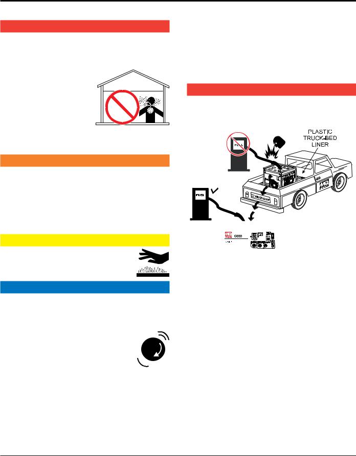
The engine fuel exhaust gases contain poisonous carbon monoxide. This gas is colorless and odorless, and can cause death if inhaled.
The engine of this equipment requires an adequate free fl ow of cooling air. NEvER
operate this equipment in any enclosed or narrow area where free fl ow of the air is
restricted. If the air fl ow is
restricted it will cause injury to people and property and serious damage to the equipment or engine.
 WARNiNg
NEvER operate the engine with heat shields or guards removed.
dO NOT remove the engine oil drain plug while the engine is hot. Hot oil will gush out of the engine crankcase and severely scald any persons in the general area of the generator.
 CAuTiON
NEvER touch the hot exhaust manifold, muffl er or cylinder. Allow these parts to cool
before servicing equipment.
NOTICE
NEvER run engine without an air fi lter or with a dirty air fi lter. Severe engine damage may occur. Service air fi lter frequently to prevent engine malfunction.
NEvER tamper with the factory settings of the engine or engine governor. Damage to the engine or equipment can result
if operating in speed ranges above the  maximum allowable.
State Health Safety Codes and Public Resources Codes specify that in certain locations, spark arresters must be used on internal combustion engines that use hydrocarbon fuels. A spark arrester is a device designed
to prevent accidental discharge of sparks or fl ames from the engine exhaust. Spark arresters are qualifi ed and rated by the United States Forest Service for this purpose. In order to comply with local laws regarding spark arresters, consult the engine distributor or the local Health and Safety Administrator.
FuEl sAFETY  dANgER
dO NOT add fuel to equipment if it is placed inside truck bed with plastic liner. Possibility exists of explosion or fi re due to static electricity.
dO NOT start the engine near spilled fuel or combustible fl uids. Diesel fuel is extremely fl ammable and its vapors can cause an explosion if ignited.
AlWAYs refuel in a well-ventilated area, away from sparks and open fl ames.
AlWAYs use extreme caution when working with fl ammable liquids.
dO NOT fi ll the fuel tank while the engine is running or hot.
dO NOT overfi ll tank, since spilled fuel could ignite if it comes into contact with hot engine parts or sparks from the ignition system.
Store fuel in appropriate containers, in well-ventilated areas and away from sparks and fl ames.
page 8 — GA6HR/GA6HRS 60 hz gENERATOR• operation and parts manual — rev. #0 (08/12/14)
Safety Information
NEvER use fuel as a cleaning agent.
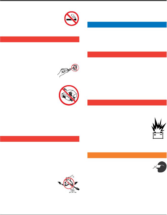
dO NOT smoke around or near the equipment. Fire or explosion could result
from fuel vapors or if fuel is spilled on a hot engine.
ElECTRiCAl sAFETY  dANgER
Turn generator and all circuit breakers OFF before performing maintenance on the generator or making contact with output receptacles.
NEvER insert any objects into the output receptacles during operation.
This is extremely dangerous. The possibility exists of electrical shock, electrocution or death.
Backfeed to a utility system can cause electrocution and/or property damage. NEvER connect the generator to a building’s electrical system without a transfer switch or other approved
device. All installations should be
performed by a licensed electrician in accordance with all applicable laws and electrical codes. Failure to do so could result in electrical shock or burn, causing serious injury or even death.
power Cord/Cable safety  dANgER
NEvER let power cords or cables lay in water.
NEvER stand in water while AC power from the generator is being transferred to a load.
NEvER use damaged or worn cables or cords when connecting equipment to generator. Inspect for cuts in the insulation.
NEvER grab or touch a live power cord or cable with wet hands. The possibility exists of electrical shock, electrocution or death.
Make sure power cables are securely connected to the generator’s output receptacles. Incorrect connections may cause electrical shock and damage to the generator.
NOTICE
AlWAYs make certain that proper power or extension cord has been selected for the job. See Cable Selection Chart in this manual.
grounding safety  dANgER
AlWAYs make sure that electrical circuits are properly grounded to a suitable earth ground (ground rod) per the National Electrical Code (NEC) and local codes before operating generator. severe injury or death by electrocution can result from operating an ungrounded generator.
NEvER use gas piping as an electrical ground.
BATTERY sAFETY (ElECTRiC sTART ONlY)
 dANgER
dO NOT drop the battery. There is a possibility that the battery will explode.
dO NOTexpose the battery to open fl ames, sparks, cigarettes, etc.The battery contains combustible gases and liquids. If these
gases and liquids come into contact with a fl ame or spark, an explosion could occur.
dO NOT charge battery if frozen. Battery can explode. When frozen, warm the battery to at least 61°F (16°C).
 WARNiNg
AlWAYs wear safety glasses when
handling the battery to avoid eye irritation.  The battery contains acids that can cause
  injury to the eyes and skin.
Use well-insulated gloves when picking up the battery.
AlWAYs keep the battery charged. If the battery is not charged, combustible gas will build up.
AlWAYs recharge the battery in a well-ventilated environment to avoid the risk of a dangerous concentration of combustible gasses.
GA6HR/6HRS 60 hz GENERATOR • operation and parts manual — rev. #0 (08/12/14) — page 9

Safety Information
If the battery liquid (dilute sulfuric acid) comes into contact with clothing or skin, rinse skin or clothing immediately with plenty of water.
If the battery liquid (dilute sulfuric acid) comes into contact with eyes, rinse eyes immediately with plenty of water and contact the nearest doctor or hospital to seek medical attention.
 CAuTiON
AlWAYs disconnect the NEgATivE battery terminal before performing service on the generator.
AlWAYs keep battery cables in good working condition. Repair or replace all worn cables.
TRANspORTiNg sAFETY
 CAuTiON
NEvER allow any person or animal to stand underneath the equipment while lifting.
NOTICE
Before lifting, make sure that the equipment parts (lifting bail if equipped) are not damaged and screws are not loose or missing.
Always make sure crane or lifi tng device has been properly secured to the lifting bail (hook) of the equipment.
AlWAYs shutdown engine before transporting.
NEvER lift the equipment while the engine is running.
Tighten fuel tank cap securely and close fuel cock to prevent fuel from spilling.
Use adequate lifting cable (wire or rope) of suffi cient strength.
Use one point suspension hook and lift straight upwards.
dO NOT lift machine to unnecessary heights.
AlWAYs tie down equipment during transport by securing the equipment with rope.
ENviRONmENTAl sAFETY/dECOmmissiONiNg
NOTICE
Decommissioning is a controlled process used to safely retire a piece of equipment that is no longer serviceable. If the equipment poses an unacceptable and unrepairable safety risk due to wear or damage or is no longer cost effective to maintain (beyond life-cycle reliability) and is to be decommissioned (demolition and dismantlement),be sure to follow rules below.
dO NOT pour waste or oil directly onto the ground, down a drain or into any water source.
Contact your country's Department of Public Works or recycling agency in your area and arrange for proper disposal of any electrical components, waste or oil associated with this equipment.
When the life cycle of this equipment is over, remove battery and bring to appropriate facility for lead reclamation. Use safety precautions when handling batteries that contain sulfuric acid.
When the life cycle of this equipment is over, it is recommended that the trowel frame and all other metal parts be sent to a recycling center.
Metal recycling involves the collection of metal from discarded products and its transformation into raw materials to use in manufacturing a new product.
Recyclers and manufacturers alike promote the process of recycling metal. Using a metal recycling center promotes energy cost savings.
page 10 — GA6HR/GA6HRS 60 hz gENERATOR• operation and parts manual — rev. #0 (08/12/14)
Safety Information
EmissiONs iNFORmATiON
NOTICE
The gasoline engine used in this equipment has been designed to reduce harmful levels of carbon monoxide (CO), hydrocarbons (HC) and nitrogen oxides (NOx) contained in gasoline exhaust emissions.
This engine has been certifi ed to meet US EPA Evaporative emissions requirements in the installed confi guration.
Attempting to modify or make adjustments to the engine emmission system by unauthorized personnel without proper training could damage the equipment or create an unsafe condition.
Additionally, modifying the fuel system may adversely affect evaporative emissions, resulting in fi nes or other penalties.
Emission Control label
The emission control label is an integral part of the emission system and is strictly controlled by regulation(s).
The label must remain with the engine for its entire life.
If a replacement emission label is needed, please contact your authorized Honda Engine Distributor.
GA6HR/6HRS 60 hz GENERATOR • operation and parts manual — rev. #0 (08/12/14) — page 11

SPECIFICATIONS (gENERATOR)
Table 1. Specifications (Generator)
|
Model |
GA6HR |
|
GA6HRS |
|
|
Type |
Brushless Revolving Field Type |
|||
AC Generator |
Excitation |
Solid State, Statically Excited System |
|||
Speed |
3,600 RPM |
||||
|
|||||
|
Cooling System |
Self-Ventilation |
|||
|
Fuel Capacity |
5 gallons (19 liters) |
|||
|
Continuous Power Output |
5.0 kW |
|||
|
Max Power Output |
6.0 kW |
|||
|
Rated Voltage |
120/240V |
|||
60 Hz AC Power |
Current Max/Continuous (120V) |
50.0/41.6 amps |
|||
Source |
Current Max/Continuous (240V) |
25.0/20.8 amps |
|||
|
Phase |
Single Phase (4 wire) |
|||
|
Frequency |
|
60 Hz |
||
|
Power Factor |
|
1 |
||
Dimensions |
|
29.9 x 30.9 X 29.7 in. |
|
29.9 x 30.9 X 29.7 in. |
|
(L x W x H) |
|
(760 X 785 X 755 mm) |
|
(760 X 785 X 755 mm) |
|
Dry Net Weight |
|
220 lbs. (100 kg.) |
|
238 lbs. (108 kg.) |
|
Battery (GA6HRS Only) |
Battery specifications for GA-6HRS : 12volts, 26Amp |
||||
hours, 260 amps cold cranking ability : |
|||||
|
|
7-1/2" (L) X 5"(W) X 7-1I4"(H) |
|||
 NOTICE
In keeping with Multiquip's policy of constantly improving its products, the specifications quoted herein are subject to change without prior notice.
page 12 — GA6HR/GA6HRS 60 hz gENERATOR• operation and parts manual — rev. #0 (08/12/14)

SPECIFICATIONS (engine)
Table 2. Specifications (Engine)
|
Model |
HONDA GX340RT2EDN2 |
|
HONDA GX340RT2EDE2 |
|
|
Type |
Air-cooled 4 stroke, Single Cylinder, OHV, Horizontal Shaft |
|||
|
Gasoline Engine |
||||
|
|
||||
|
Bore X Stroke |
3.46 in. X 2.52 in. |
|||
|
(88 mm x 64 mm.) |
||||
|
|
||||
Engine |
Displacement |
23.70 cu-in (389 cm3) |
|||
Max Output |
11.0 H.P./3600 R.P.M. |
||||
|
|||||
|
Fuel |
Unleaded Automobile Gasoline |
|||
|
Lube Oil Capacity |
1.16 quarts (1.1 liters) |
|||
|
Oil Alert System |
|
Yes |
||
|
Speed Control Method |
Centrifugal Fly-weight Type |
|||
|
Starting Method |
Recoil Start |
|
Electric Start |
|
Dimensions |
|
15.0 x 17.7 X 17.4 in. |
|
15.0 x 17.7 X 17.4 in. |
|
(L x W x H) |
|
(380 X 450 X 443 mm) |
|
(380 X 450 X 443 mm) |
|
Dry Net Weight |
|
68.4 lbs. (31 kg.) |
|
68.4 lbs. (31 kg.) |
|
Effects of Altitude and Heat
The maximum output of the engines listed above are applicable to supplying electrical power for continuous service at ambient conditions in accordance with SAE Test cord J607. The above ambient conditions are at standard sea level, with a barometric reading of 29.92 inches and a temperature of 60° F (15.5° C).
Generally, the engine's output power will decrease 3-1/2% for each 1000 feet (305 meters) of altitude above sea level, and 1% for each 10° F (-12.2° C) above the standard temperature of 60° F (15.5° C).
GA6HR/6HRS 60 hz GENERATOR • operation and parts manual — rev. #0 (08/12/14) — page 13
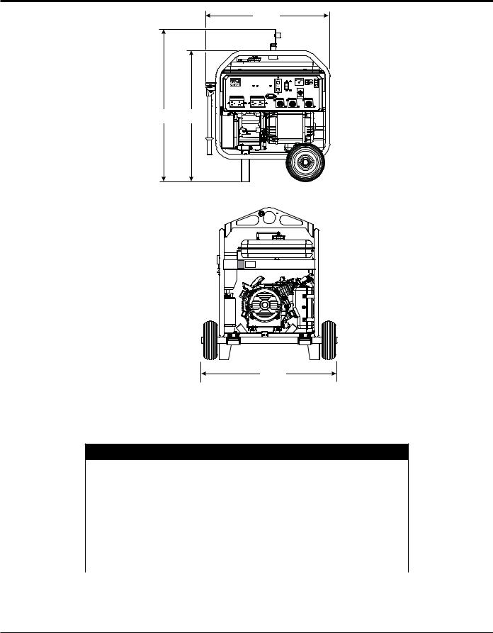
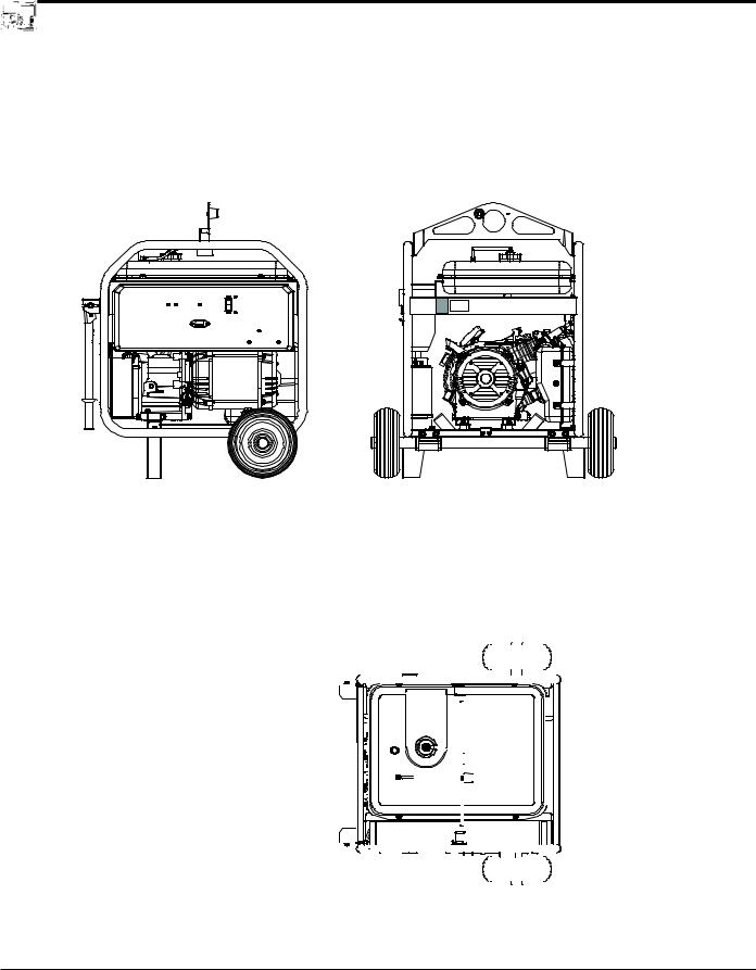
dimensions
C
 GA-6HR
V 120
120
AC VOLTMETER
120V
AC CIRCUIT BREAKER
GFCI PROTECTED
A B
D
Figure 2. Dimensions
Table 3. Generator Dimensions
REFERENCE |
DESCRIPTION |
DIMENSIONS: IN. (MM) |
|
LETTER |
|||
|
|
||
A |
HEIGHT (LIFTING BALE) |
34.1 (865) |
|
|
|
|
|
B |
HEIGHT (FRAME) |
29.7 (755) |
|
|
|
|
|
C |
LENGTH |
29.9 (760) |
|
|
|
|
|
D |
WIDTH |
30.9 (785) |
|
|
|
|
page 14 — GA6HR/GA6HRS 60 hz gENERATOR• operation and parts manual — rev. #0 (08/12/14)

note
GA6HR/6HRS 60 hz GENERATOR • operation and parts manual — rev. #0 (08/12/14) — page 15
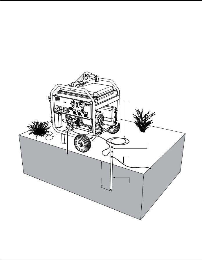
installation
Connectingthe Ground
The nut and ground terminal on the generator should always be used to connect the generator to a suitable ground.The ground cable should be #8 size wire (aluminum) minimum. If copper wire is used, #10 size wire minimum should be used
At the generator, connect the terminal of the ground cable between the lock washer and the nut (Figure 3) and tighten the nut fully. Connect the other end of the ground cable to a suitable earth ground (ground rod).
 GA-6HR
GROUND CABLE (#8 MINIMUM)
|
GROUND ROD |
|
FOR EARTH GROUND |
GENERATOR |
CONNECT TO |
BUILDING GROUND |
|
GROUND LUG |
IF REQUIRED |
8 FT.
MINIMUM
REFERENCE
NEC 250-52(C)
Figure 3. Generator Grounding
page 16 — GA6HR/GA6HRS 60 hz gENERATOR• operation and parts manual — rev. #0 (08/12/14)
installation
Outdoor Installation
If possible install the generator in a area that is free of debris, bystanders, and overhead obstructions. Make sure the generator is on secure level ground so that it cannot slide or shift around.
The installation site must be relatively free from moisture and dust. All electrical equipment should be protected from excessive moisture. Failure to do will result in deterioration of the insulation and will result in short circuits and grounding.
Foreign materials such as dust, sand, lint and abrasive materials have a tendency to cause excessive wear to engine and alternator parts.
 WARNING
Pay close attention to ventilation when operating the generator inside tunnels and caves. The engine exhaust contains noxious elements. Engine exhaust must be routed to a ventilated area
Indoor Installation
Exhaust gases from gas engines are extremely poisonous. Whenever an engine is installed indoors the exhaust fumes must be vented to the outside. The engine should be installed at least two feet from any outside wall. Using an exhaust pipe which is too long or too small can cause excessive back pressure which will cause the engine to heat excessively and possibly burn the valves.
placement
The generator should always be placed on a flat level surface when it is running. DO NOT place the generator on slopes, the possibility exists that the generator could slide.
 DANGER
An electric shock is apt to happen when vibrators are used. Pay close attention to handling when operating vibrators and always use rubber boots and gloves to insulate the body from a short circuit.
Generator Grounding
To guard against electrical shock and possible damage to the equipment, it is important to provide a good EARTH ground.
Article 250 (Grounding) of the National Electrical Code (NEC) provides guide lines for proper grounding and specifies that the cable ground shall be connected to the grounding system of the building as close to the point of cable entry as practical.
NEC articles 250-64(b) and 250-66 set the following grounding requirements:
1.Use one of the following wire types to connect the generator to earth ground.
a.Copper - 10 AWG (5.3 mm2) or larger.
b.Aluminum - 8 AWG (8.4 mm2) or larger.
2.When grounding the generator (Figure 3) connect the ground cable between the lock washer and the nut on the generator and tighten the nut fully. Connect the other end of the ground cable to earth ground.
3.NEC article 250-52(c) specifies that the earth ground rod should be buried a minimum of 8 ft. into the ground.
 NOTICE
When connecting the generator to any buildings electrical system ALWAYS consult with a licensed electrician.
GA6HR/6HRS 60 hz GENERATOR • operation and parts manual — rev. #0 (08/12/14) — page 17

general information
FAMILIARIZATION
Generator
The Multiquip GA6HR/GA6HRS generator is designed as a portable dual purpose power source for 60 Hz (single phase) lighting facilities, power tools, submersible pumps and other industrial and construction machinery.
The generator is mounted on rubber vibration isolators that have a steel base backplate which is attached to the protective steel pipe carrying frame.
The protective carrying frame is made of steel tubing and fully wraps around the generator to protect against damage. Reference Figure 4, Figure 5 and Figure 8 for the basic controls and indicators for the GA6HR/GA6HRS generators.
These portable generator are supplied with a electrical control box (panel). To reduce vibration caused by the engine, the control box is also placed on rubber isolators.
Control Panel
The control panel is provided with the following:
120V Twist-Lock Output Receptacle (L5-20R)
120V Twist-Lock Output Receptacle (L5-30R)
120/240V Twist-Lock Output Receptacle (L14-30R)
120 VAC GFCI Receptacle (2)GFCI Sensing Module
23 Amp Main Circuit Breaker.
AC Voltmeter
Idle Control Switch
Full Power Switch
Operation Switch
Hour Meter
Start Switch (GA6HRS only)
 DANGER
Before connecting this generator to any building’s electrical system, a licensed electrician must install an isolation (transfer) switch.
Serious injury or death may result without this transfer switch.
page 18 — GA6HR/GA6HRS 60 hz gENERATOR• operation and parts manual — rev. #0 (08/12/14)
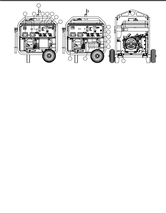
components (generator)
|
3 |
|
|
|
|
1 |
2 |
|
4 |
5 |
6 |
|
|
|
|
|
7 |
|
|
|
|
|
8 |
|
GA-6HR |
|
|
|
|
|
|
|
|
V 120 |
|
|
|
|
|
120 |
|
|
|
|
|
IDLE |
|
|
|
|
|
AC VOLTMETER CONTROL |
|
|
|
|
|
120V |
|
|
|
AC CIRCUIT BREAKER |
|
||
|
QUARTZ |
|
GFCI PROTECTED |
|
|
120V |
120V |
|
|
|
|
20A |
20A |
120V |
120V |
120/240V |
|
|
20A |
|
30A |
30A |
|
|
|
GA-6HRS |
|
|
|
|
|
8 |
|
|
|
|
|
|
V 120 |
|
|
|
|
|
|
|
120 |
|
|
|
|
|
|
|
|
|
IDLE |
|
|
|
|
|
|
|
AC VOLTMETER CONTROL |
|
|
|
|
|
|
|
|
|
120V |
|
|
|
|
|
|
AC CIRCUIT BREAKER |
|
OPERATION |
9 |
|
|
|
|
QUARTZ |
|
GFCI PROTECTED |
|
SWITCH |
|
20A |
120V |
20A |
120V |
120V |
120V |
120/240V |
|
|
|
|
|
20A |
|
30A |
30A |
|
|
|
|
|
|
|
|
|
START |
|
|
|
|
|
|
|
|
SWITCH |
|
|
|
|
|
|
|
|
|
10 |
|
|
|
|
|
|
|
|
11 |
|
|
|
|
|
|
|
|
12 |
14 |
|
|
13 |
|
|
|
|
|
15
Figure 4. Generator Components
1.GFCI Duplex Receptacles – NEMA 5-20R, GFCI receptacle will provide 120V@ 20 amps.
2.HourMeter –Indicates the number hours the generator has been in use.
3.Lifting Ball Eye – Attach a rope or chain to this lifting eye when lifting of the generator is required. Never stand underneath the generator while it is being lifted. Place lifting eye in down position when not in use.
4.GFCI Sensing Module – Interrupts power when a ground fault exist.
5.Main Breaker – This 2-pole, 23 amp circuit breaker protects the generator from short circuiting or overloading. When starting the generator always have the circuit breaker placed in the "OFF" position.
6.AC-Voltmeter – This voltmeter indicates (with a mark) the rated 60 Hz (single-phase) output voltage. In addition the voltmeter can also be used as a diagnostic tool. If the voltmeter indicator (needle) is below the rated voltage, engine problems may exist (low/high RPM's).To prevent damage to the generator or power tools turn the generator OFF and consult your authorized Multiquip service dealer.
7.Idle Control Switch – The generator is provided with an automatic idle control device for noise suppression and reduced fuel consumption.
The automatic idle control automatically engages under a no-load condition. With the automatic idle control
switched “ON”, the engine revolutions will automatically drop to about 2600 rpm (low-speed operation) within 3 seconds after the load stops. When the operation is resumed, the engine speed is automatically increased to about 3600 rpm (high-speed operation) as soon as the load is connected.
8.Operation Switch – Place switch in the "ON" position (up) for normal operation. To turn-off the generator, place the operation switch in the "OFF" position (down)
9.Start Switch – Press this pushbutton switch to start the generator (GA6HRS only).
10.120/240V Output Receptacle –NEMA L14-30R twistlock receptacle will provide 240V, 60 Hz @ 20.8 amps, or 120V@ 41.6 amps (X2) 60 Hz. Depending on the position of the full power switch.
11.120V Output Receptacle – NEMA L5-30R twist-lock receptacle will provide 120V, 30 amps, 60 Hz.
12.120V Output Receptacle – NEMA L5-20R twist-lock receptacle will provide 120V, 20 amps, 60 Hz.
13.Battery – This unit is equipped with a 12 VDC battery. Replace with only recommended type battery (GA6HRS only).
14.Charcoal Canister – A container filled with activated charcoal that traps gasoline vapors emitted by the fuel system.
15.Ground – This ground connection point should be connect to a good earth ground (ground rod).
GA6HR/6HRS 60 hz GENERATOR • operation and parts manual — rev. #0 (08/12/14) — page 19

components (generator)
|
GA-6HR |
|
|
|
|
GA-6HRS |
|
0N |
|
|
|
|
V 120 |
0N |
|
|
V 120 |
|
|
|
|
|
120 |
OFF |
|
|
120 |
OFF |
|
|
|
|
IDLE |
|
|
|
IDLE |
|
|
|
|
|
|
|
|
IDLE |
|
|
|
|
|
|
AC VOLTMETER CONTROL |
|
|
|
AC VOLTMETER CONTROROL L |
|
|
|
|
|
120V |
|
|
|
120V |
|
|
|
|
|
AC CIRCUIT BREAKER |
16 |
|
|
AC CIRCUIT BREAKER |
OPERATION |
16 |
|
|
QUARTZ |
GFCI PROTECTED |
|
QUARTZ |
GFCI PROTECTED |
SWITCH |
||
120V |
120V |
|
120V |
120V |
|
|
20A |
20A |
120V |
120V |
120/240V |
20A |
20A |
120V |
120V |
120/240V |
|
20A |
|
30A |
30A |
|
20A |
|
30A |
30A |
|
|
|
|
|
|
|
|
|
START |
|
|
|
|
|
|
|
|
|
SWITCH |
Figure 5. Full Power Switch
16.Full Power Switch – The generator is provided with a full power switch. Figure 6 and Figure 7 show simplified wiring diagrams of the dual voltage system.
When the full power switch is in the 120 volt (up) position, you can access the full rated power of the generator at 120 volts from the GFCI duplex receptacle and the120V twist-lock receptacle, or a combination of both receptacles as long as the total load does not exceed the generating set capacity.
|
|
|
|
CON1 |
CON3 |
|
V |
|
|
CB |
|
U1 |
H |
|
|
|
|
|
W |
|
|
|
CON5 |
V1 |
|
|
|
|
|
U2 |
|
|
|
|
|
V2 |
SW 120V |
22 |
CON2 |
||
9 |
8 |
7 |
|
||
|
|
|
|||
|
6 |
5 |
4 |
|
|
|
3 |
2 |
1 |
|
CON4 |
Figure 6. 120V Full Power Switch
Simplified Diagram (Up Position)

 NOTICE
When the full power switch is in the 120V position, the 240V twist-lock receptacle cannot be used..
When the switch is in the 240 volt (down) position, you can access half of the rated power of the generating set at 120 volts from the GFCI duplex receptacle and up to half of the rated power of the set at 120 volts from 120V twist-lock receptacle; or full rated power of the set at 240 volts from the 240V twist-lock receptacle.
|
|
|
|
CON1 |
CON3 |
|
V |
|
|
CB |
|
U1 |
H |
|
|
|
|
|
W |
|
|
|
CON5 |
V1 |
|
|
|
|
|
U2 |
|
|
|
|
|
|
SW 120/240V |
22 |
CON2 |
||
V2 |
|
|
|
||
9 |
8 |
7 |
|
||
|
|
|
|||
|
6 |
5 |
4 |
|
|
|
3 |
2 |
1 |
|
CON4 |
Figure 7. 240/120V Full Power Switch
Simplified Diagram (Down Position)
 NOTICE
When using a combination of receptacles, total load should not exceed the rated capacity of the generator.
page 20 — GA6HR/GA6HRS 60 hz gENERATOR• operation and parts manual — rev. #0 (08/12/14)
components (generator)
19 |
17 |
18 |
|
|
24 |
25 |
|
|
|
|
6kW |
26 |
|
|
|
|
|
|
|
20 |
|
27 |
|
|
|
|
|
|
|
21 |
|
28 |
23 |
22 |
30 |
29 |
|
Figure 8. Generator Components (Continued)
17.Fuel Gauge – This gauge is located on top of the fuel tank. Read this gauge to determine when fuel is low.
18.Fuel Tank Cap – Remove this cap to add unleaded gasoline to the fuel tank. Replenish with clean unleaded gasoline. Make sure cap is tightened securely. DO NOT over fill.
19.Fuel Tank – Capacity is 5 gallons (19 liters). Fill with unleaded gasoline.
20.Recoil Starter (pull rope) – Manual-starting method. Pull the starter grip until resistance is felt, then pull briskly and smoothly.
21.Engine Oil Filler Cap – Remove this cap/dipstick when the adding of engine oil is required. See Table 2 for recommended type engine oil.
22.Engine Oil Drain Plug – Remove this drain plug when draining of the oil from the engine crankcase is required. Fill with recommended type oil as listed in Table 4.
23.Air Cleaner – Prevents dirt and other debris from entering the fuel system. Remove wing-nut on top of air filter cannister to gain access to filter element. NEVER run the engine without an air cleaner.
24.Muffler/Heat Shield – Used to reduce noise and emissions. NEVER touch this heat shield when the generator/welder is in use. Always allow time for engine to cool before servicing.
25.Spark Plug – Provides spark to the ignition system. Set spark plug gap to 0.6 - 0.7 mm (0.028 - 0.031 inch) Clean spark plug once a week.
26.Fuel Cock Lever – Turn this lever downward to start (down)the flow of fuel into the carburetor. Turn upward to stop (up) the flow of fuel.
27.Choke Lever – Used for starting the engine. Close the choke lever when starting a cold engine or in cold weather conditions. The choke enriches the fuel mixture. Open the choke lever if starting a warm engine or in warm weather conditions.
28.Transport Handle (Option) – When transporting of the generator is required, lift up on each handle and engage locking pin. Part of wheel kit assembly
29.Support Stand (Option) – Supports the generator, part of wheel kit assembly
30.Foam-Filled Tires (Option) – Provided for ease of transport. Replace with only recommended tires.
 NOTICE
This HONDA engine is equipped with a low oil shutdown capability. A built in sensor will automatically turn off the engine should the oil level fall below a safe operating condition. Make sure the generators is placed on level ground. Placing the generators on level ground will ensure that the low oil sensor will function properly.
GA6HR/6HRS 60 hz GENERATOR • operation and parts manual — rev. #0 (08/12/14) — page 21
INSPECTION/SETUP
General Inspection Priorto Operation
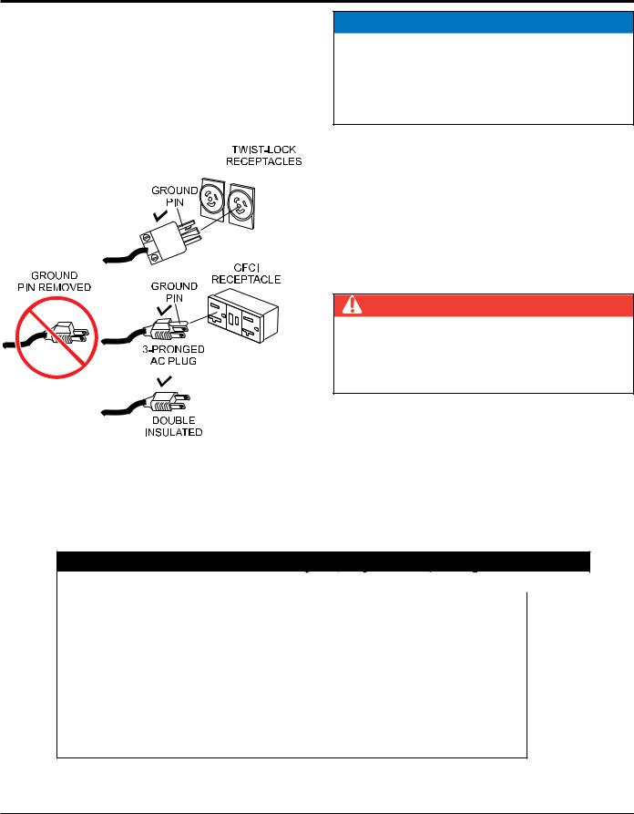
Ground PowerTools
When using power tools or electrical equipment requiring AC power from the generator, make sure power tool cord has a ground pin or is double insulated as shown in Figure 9.
 NOTICE
Double-insulated power tools and small appliances have specially insulated housings that eliminate the need for a ground pin.These types of double-insulated power cords are designed so that no part of the device will be electrically live even if the internal insulation fails.
Extension Cable
When electric power is to be provided to various tools or loads at some distance from the generator, extension cords are normally used. Cables should be sized to allow for distance in length and amperage so that the voltage drop between the generator and point of use (load) is held to a minimum. Use the cable selection chart (Table 4) as a guide
proper cable size.
 DANGER
NEVER use power tools or equipment that do not have a ground capability, the possibility exists of electrocution, electrical shock or burn, which can cause severe bodily harm or even DEATH!
Figure 9. Ground Pin
Table 4. Cable Selection (60 Hz, Single Phase Operation)
Current In |
Load In Watts |
|
Maximum Allowable Cable Length |
|
|||
Amperes |
120 Volts |
240 Volts |
#10 Wire |
|
#12 Wire |
#14 Wire |
#16 Wire |
2.5 |
300 |
600 |
1000 ft. |
|
600 ft. |
375 ft. |
250 ft. |
5 |
600 |
1200 |
500 ft. |
|
300 ft. |
200 ft. |
125 ft. |
7.5 |
900 |
1800 |
350 ft. |
|
200 ft. |
125 ft. |
100 ft. |
10 |
1200 |
2400 |
250 ft. |
|
150 ft. |
100 ft. |
|
15 |
1800 |
3600 |
150 ft. |
|
100 ft. |
65 ft. |
|
20 |
2400 |
4800 |
125 ft. |
|
75 ft. |
50 ft. |
|
CAUTION: Equipment damage can result from low voltage.
page 22 — GA6HR/GA6HRS 60 hz gENERATOR• operation and parts manual — rev. #0 (08/12/14)
INSPECTION/setup
Before Starting

 NOTICE
ALWAYS place the main circuit breaker in the OFF position prior to starting the engine.
1.Read safety instructions at the beginning of manual.
2.Clean the generator, removing dirt and dust, particularly the engine cooling air inlet, carburetor and air cleaner.
3.Check the air filter for dirt and dust. If air filter is dirty, replace air filter with a new one as required.
4.Check carburetor for external dirt and dust. Clean with dry compressed air.
5.Check fastening nuts and bolts for tightness.
Battery Setup (GA6HRS)
 CAUTION
Use all safety precautions specified by the battery manufacturer when working with the battery. See Safety Information section of this manual for more details on battery safety.
1.Place the battery into the battery cradle and secured with mounting hardware.
2.Connect the positive cable to the positive terminal on the battery first, then connect the negative cable to the negative terminal.
Engine Oil Check
1.To check the engine oil level, place the generator on secure level ground with the engine stopped.
2.Remove the filler dipstick from the engine oil filler hole (Figure 10) and wipe clean.
Figure 10. Engine Oil Dipstick Removal
3.Insert and remove the dipstick without screwing it into the filler neck. Check the oil level shown on the dipstick.
4.If the oil level is low (Figure 11), fill to the edge of the oil filler hole with the recommended oil type (Table 5). Maximum oil capacity is 1.16 quarts (1.1 liters).
Figure 11. Engine Oil Dipstick(Oil Level)
Table 5. OilType
Season |
Temperature |
OilType |
Summer |
25°C or Higher |
SAE 10W-30 |
Spring/Fall |
25°C~10°C |
SAE 10W-30/20 |
Winter |
0°C or Lower |
SAE 10W-10 |
Fuel Check
1.Close the fuel cock before filling the fuel tank.
2.Remove the fuel cap located on top of fuel tank.
3.Read the fuel gauge located on top of the fuel tank (Figure 12) to determine if the fuel level is low. If fuel is low, replenish with clean unleaded fuel.
Figure 12. Fuel Gauge
4.When refueling, be sure to use a strainer for filtration. DO NOT top-off fuel. DO NOT fill the tank beyond capacity. Wipe up any spilled fuel immediately!
GA6HR/6HRS 60 hz GENERATOR • operation and parts manual — rev. #0 (08/12/14) — page 23
operation
This section is intended to assist the operator with the initial start-up of the portable generator. It is extremely important that this section be read carefully before attempting to use the generator in the field.
Before Starting the Engine

 NOTICE
Both model generators are equipped with a GFCI sensing module. The purpose of this module is to sense a ground fault during operation of the generator and shut down the generator once the ground fault has been detected.
Multiquip recommends that the GFCI sensing module be tested before each use of the generator. Reference the maintenance section of this manual for the testing of the GFCI sensing module.
1.Be sure to disconnect all electrical loads from the generator prior to starting the engine.
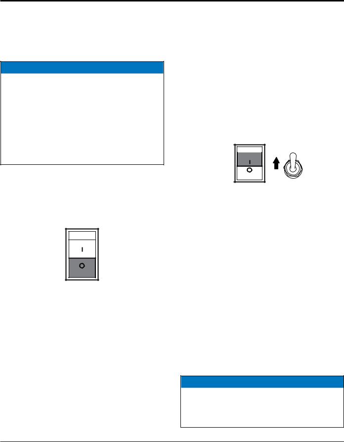
2.NEVER start the engine with the main circuit breaker in the ON position.Always place circuit breaker (Figure 13) in the OFF position before starting.
ON
OFF
Figure 13. Main Circuit Breaker (OFF)
Starting the Engine (Recoil Start)
1.Place the engine fuel valve lever (Figure 14) in the ON position.
Figure 14. Engine Fuel Valve Lever (ON)
2.Place the choke lever (Figure 15) in the CLOSED position if starting a cold engine.
Figure 15. Choke Lever
3.Place the choke lever (Figure 15) in the OPEN position if starting a warm engine or the temperature is warm.
4.Place the generator's operation switch (Figure 16) in the ON position.
ON
ON |
OFF
GA6HRS
GA6HR
Figure 16. Operation Switch (ON)
5.If your generator is a recoil start only (no battery), grasp the starter grip (Figure 17) and slowly pull it out. The resistance becomes the hardest at a certain position, corresponding to the compression point. Pull the starter grip briskly and smoothly for starting.
Proceed to step 6 if your unit is an electric start model (battery installed).
Figure 17. Starter Grip
 NOTICE
DO NOT pull the starter rope all the way to the end.
DO NOT release the starter rope after pulling. Allow it to rewind as soon as possible..
page 24 — GA6HR/GA6HRS 60 hz gENERATOR• operation and parts manual — rev. #0 (08/12/14)
operation
6.Press the generator's pushbutton start switch (Figure 18) and listen for the engine to start.
Figure 18. Start Switch (GA6HRS Only)
7.If the engine has started, slowly return the choke lever (Figure 15) to the OPEN position. If the engine has not started repeat steps 1 through 6.
8.Before the generator is placed into operation, run the engine for 3-5 minutes. Check for abnormal smells, fuel leaks, and noises that would associate with loose components.
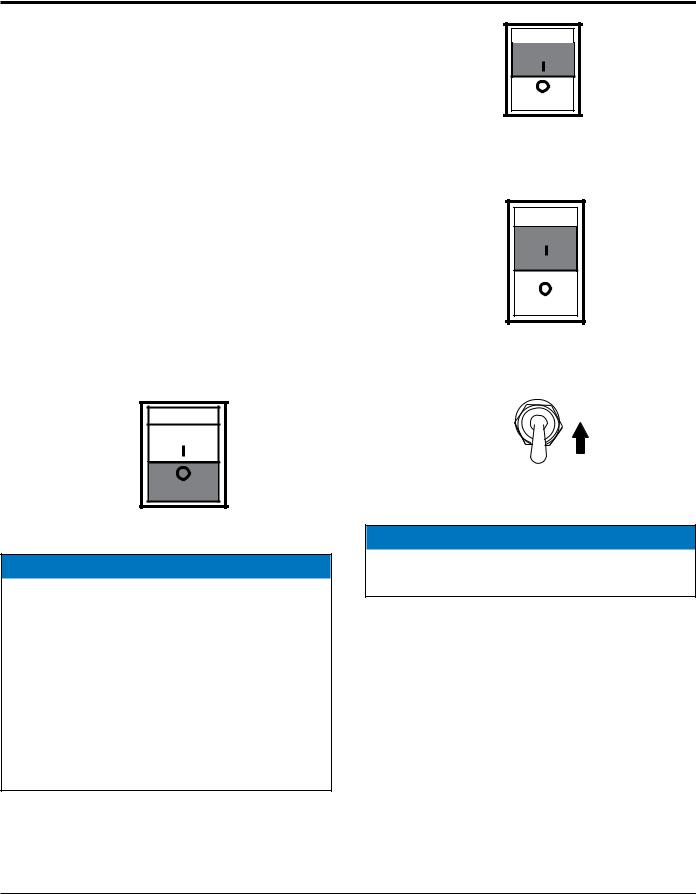
9.Place idle control switch (Figure 19) in the OFF position.This will allow the engine speed to run at about 3600 RPM's.
ON
OFF
Figure 19. Idle Control Switch (OFF)

 NOTICE
Placing the idle control switch in the OFF position (Figure 19) allows the engine to operate at a maximum speed of about 3600 RPM's.
When the idle control switch (Figure 20) is placed in the up position (ON), the generator will run at idle speed (2200 RPM's) until a load is applied, at that time the engine speed will increase to 3600 RPM's as long as a load is being applied.
When the load is not in use, the engine speed will drop back to the idle mode after about 3 seconds.
ON |
OFF
Figure 20. Idle Control switch (ON)
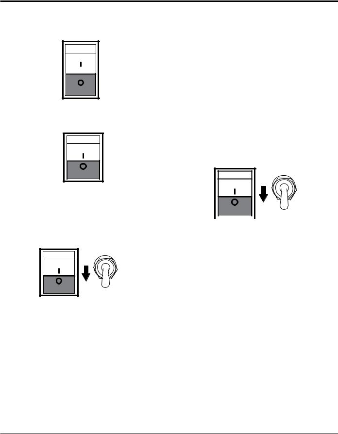
10.Place main circuit breaker (Figure 21) in the ON position.
ON |
OFF
Figure 21. Main Circuit Breaker (ON)
11.Place the full power switch (Figure 22) in the 120V position (up).
UP
240/120V
Figure 22. Full Power Switch 120V Position (Up)
 NOTICE
When the full power switch is in the 120V position, the 240V twist-lock receptacle cannot be used.
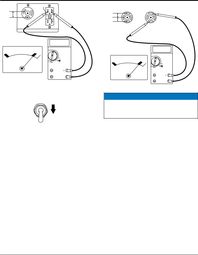
12.Read voltmeter on front panel of generator (Figure 23) and verify that 120 VAC is displayed. Using an external voltmeter as shown in Figure 23, verify that 120 VAC is present at the 120V twist-lock and GFCI duplex receptacles.
GA6HR/6HRS 60 hz GENERATOR • operation and parts manual — rev. #0 (08/12/14) — page 25
operation
GFCI
W
G
120VAC
X L5-30R
120V
120 VAC
OFF V~
V
300 mV 
V |
120 |
A |
A~ |
V

COM
Figure 23. 120V Twist-Lock/GFCI Receptacles
13.Place the full power switch (Figure 24) in the 240/120V position (down).
DOWN
240/120V
Figure 24. Full Power Switch 240/120V Position (Down)
14.Read voltmeter on front panel of generator (Figure 25) and verify that 240 VAC is displayed. Using an external voltmeter as shown in Figure 25, verify that 240 VAC is present at the 120/240V, L14-30R twist-lock receptacle.
|
120VAC |
|
240VAC |
|
L14-30R |
X |
|
X |
|
120VAC W |
|
L14-30R |
|
|
G |
W |
G |
||
120VAC |
||||
|
|
|
||
|
Y |
|
Y |
240 VAC
OFF V~
V
300 mV 
A A~
V 240
V

COM
Figure 25. 120/240V L14-30R Receptacle
 NOTICE
When using a combination of dual receptacles, total load should not exceed the rated capacity of the generator.
15.Connecting of loads (power tools, lighting etc.) to the generator receptacles can now be done.
page 26 — GA6HR/GA6HRS 60 hz gENERATOR• operation and parts manual — rev. #0 (08/12/14)
shutdown
Stopping the Engine (Normal Shutdown)
1.Place main circuit breaker (Figure 26) in the OFF position.
ON
OFF |
Figure 26. Main Circuit Breaker (OFF)
2. Place idle control switch (Figure 27) in the OFFposition.
ON
OFF |
Figure 27. Idle Control switch (OFF)
3.Let engine run at idle with no load for 2-3 minutes.
4.To shut-down the engine, place the generator's operation switch (Figure 28) in the OFF position).
GA6HRS
ON
OFF
OFF
GA6HR
Figure 28. Operation Switch (OFF)
5.Place engine fuel valve lever (Figure 29) in the OFF position.
Figure 29. Engine Fuel Valve Lever (OFF)
6. Remove all loads from the generator.
Emergency Shutdown
1. Place operation switch (Figure 30) in the OFF position.
GA6HRS
ON
OFF
 OFF GA6HR
Figure 30. Operation Switch (Emergency)
GA6HR/6HRS 60 hz GENERATOR • operation and parts manual — rev. #0 (08/12/14) — page 27

preparation for long term storage
Generator Storage
For storage of the generating set for over 30 days, the following is required:
Drain the fuel tank completely, or add STA-BIL to the fuel.
Run the engine until the gasoline in the carburetor is completely consumed.
Completely drain the oil from the crankcase and refill with fresh oil.
Remove the spark plug, pour 2 or 3 cc of SAE 30 oil into the cylinder and crank slowly to distribute the oil.
Slowly rotate the engine a few times with the starter rope and install a new plug.
Pull out the starter rope slowly and stop at the compression point.
Clean all external parts of the generating set with a cloth.
Cover the generating set and store in a clean, dry place.
page 28 — GA6HR/GA6HRS 60 hz gENERATOR• operation and parts manual — rev. #0 (08/12/14)
 Loading...