


PARTS AND OPERATION MANUAL
© COPYRIGHT 2001, MULTIQUIP INC.
Concrete Pump
Model C-30HD
Revision #4 (03/06/01)
MULTIQUIP INC. |
PARTS DEPARTMENT: |
18910 WILMINGTON AVE. |
800-427-1244 |
CARSON, CALIFORNIA 90746 |
FAX: 800-672-7877 |
310-537-3700 |
SERVICE DEPARTMENT/TECHNICAL ASSISTANCE: |
800-421-1244 |
800-478-1244 |
FAX:310-537-3927 |
FAX:310-631-5032 |
E-mail:mq@multiquip.com • www:multiquip.com
Atlanta • Boise • Dallas • Houston • Newark Montreal, Canada • Manchester, UK
Rio De Janiero, Brazil • Guadalajara, Mexico

PAGE 2 — C-30HD — PARTS & OPERATION MANUAL — REV. #4 (03/06/01)
HERE'S HOW TO GET HELP
PLEASE HAVE THE MODEL AND SERIAL NUMBER ON-HAND WHEN CALLING
PARTS DEPARTMENT
800-427-1244 or 310-537-3700 FAX: 800-672-7877 or 310-637-3284
SERVICE DEPARTMENT/TECHNICAL ASSISTANCE
800-478-1244 or 310-537-3700 FAX: 310- 537-4259
WARRANTY DEPARTMENT
888-661-4279, or 310-661-4279 FAX: 310- 537-1173
MAIN
800-421-1244 or 310-537-3700 FAX: 310-537-3927
C-30HD — PARTS & OPERATION MANUAL — REV. #4 (03/06/01) — PAGE 3

Here's how to get help ............................................ |
3 |
Table of contents ..................................................... |
4 |
Parts ordering procedures ...................................... |
5 |
C-30HD |
|
Specifications .......................................................... |
6 |
Pump Warranty ....................................................... |
7 |
Safety Instructions .................................................. |
8 |
Important Hand Signals .......................................... |
9 |
General Information .............................................. |
10 |
How it Works .................................................... |
12-13 |
Operating Information/Clean-Up Procedures .. |
14-18 |
Concrete Mix Information ................................ |
19-22 |
Slump Test Procedure ........................................... |
23 |
Explanation Of Codes In Remarks Column .......... |
24 |
Suggested Spare Parts ......................................... |
25 |
Component Illustrations |
|
Control Panel......................................................... |
25 |
Frame ............................................................... |
26-27 |
Gasoline Engine Control ................................. |
28-29 |
Diesel Engine Control ...................................... |
30-31 |
Manifold Assembly (Exploded View) .................... |
33 |
Concrete Delivery ............................................ |
34-35 |
Clutch Assembly ................................................... |
36 |
Crankshaft Assembly (Exploded View) ........... |
38-39 |
Crankshaft Assembly ....................................... |
40-41 |
Countershaft Assembly ................................... |
42-43 |
Compensator Piston Rod ................................ |
44-45 |
Connnecting Rod Assembly (Old Style) .......... |
46-47 |
Connnecting Rod Assembly (New Style) ........ |
48-49 |
Rocker Assembly ............................................. |
50-51 |
Compensating Spring Assembly .......................... |
52 |
Return Spring Assembly ....................................... |
53 |
Oil System and Fuel System ........................... |
54-55 |
Central Grease Lubrication Panel ......................... |
56 |
Axle Installation ................................................ |
58-59 |
NOTE: Specification and part number are subject to change without notice.
TABLE OF CONTENTS |
|
Hopper and Hood ............................................ |
60-61 |
Optional Features |
|
C-30MG Scaled Down Manifold/Cylinder Kit ........ |
62 |
C-30MG Manifold Assembly ............................ |
64-65 |
C-30MG Piston Head Components ................. |
66-67 |
C-30SP Optional Screw Conveyor |
|
and Torque Limiter ........................................... |
68-69 |
Recommended Shotcrete System .................. |
70-71 |
Shotcrete Accessories ..................................... |
72-73 |
Service Information |
|
Service Procedures ......................................... |
74-75 |
Manufacturing Changes................................... |
76-78 |
Remote Controls, Engine RPM ............................ |
79 |
Wiring Schematic ............................................. |
80-81 |
Linkage Adjustment (Old Style Solenoid) ............ |
82 |
Torque Limiter Model (C30SP Option) ................. |
83 |
Bearing Installation ............................................... |
84 |
Connecting Rod Assembly ................................... |
85 |
Piston Head Lubrication System .......................... |
86 |
Return Spring Adjustment Procedure .................. |
87 |
Belt and Chain Adjustment ................................... |
88 |
Roller Chain — Application Information .......... |
89-90 |
Terms and Conditions of Sale — Parts ................. |
91 |
PAGE 4 — C-30HD — PARTS & OPERATION MANUAL — REV. #4 (03/06/01)
PARTS ORDERING PROCEDURES
nDealer account number
nDealer name and address
nShipping address (if different than billing address)
nReturn fax number
nApplicable model number
nQuantity, part number and description of each part
nSpecify preferred method of shipment:
•UPS Ground
•UPS Second Day or Third Day*
•UPS Next Day*
•Federal Express Priority One (please provide us with your Federal Express account number)*
•Airborne Express*
•Truck or parcel post
*Normally shipped the same day the order is received, if prior to 2PM west coast time.
Earn Extra Discounts when you order by FAX!
All parts orders which include complete part numbers and are received by fax qualify for the following extra discounts:
Number of |
|
line items ordered |
Additional Discount |
1-9 items |
3% |
10+ items** |
5% |
Get special freight allowances when you order 10 or more line items via FAX!**
nUPS Ground Service at no charge for freight
nPS Third Day Service at one-half of actual freight cost
No other allowances on freight shipped by any other carrier.
**Common nuts, bolts and washers (all items under $1.00 list price) do not count towards the 10+ line items.
*DISCOUNTS ARE SUBJECT TO CHANGE*
Fax order discount and UPS special programs revised June 1, 1995
Extra |
Fax |
Discount |
||||
|
|
USA |
||||
|
|
|
||||
for |
Domestic |
|
||||
Dealers |
Only |
|||||
|
||||||
|
|
|
||||
Now! Direct TOLL-FREE access to our Parts Department!
Toll-free nationwide:
800-421-1244 Toll-free FAX:
800/6-PARTS-7 • 800-672-7877
C-30HD — PARTS & OPERATION MANUAL — REV. #4 (03/06/01) — PAGE 5

|
C-30HD SPECIFICATIONS |
|
|
PERFORMANCE |
|
Pumping Rate .................................................................................................................. |
25 cu. yds. per hour |
Maximum Aggregate Size ................................................................................................ |
1/2" minus (35mm) |
Verticle Pumping Height ................................................................................................... |
Excess of 100 ft. (60 m) |
Horizontal Pumping Distance ........................................................................................... |
400 to 500 ft. (300 m) |
Engine — Gas .................................................................................................................. |
30 HP Wisconsin VH4D |
Engine — Diesel .............................................................................................................. |
30 HP Hatz Z790 |
Pump ................................................................................................................................ |
Reciprocating piston |
Remote Control ................................................................................................................ |
Standard |
Hopper Capacity .............................................................................................................. |
6 cu. ft. |
Material Hose ................................................................................................................... |
2" or 2 1/2" |
DIMENSIONS |
|
L x W x H .......................................................................................................................... |
10 ft. x 4 1/2 ft. x 4 1/2 ft. |
Weight .............................................................................................................................. |
2,200 lbs. |
Tire Size ........................................................................................................................... |
7.35 - 14 |
PAGE 6 — C-30HD — PARTS & OPERATION MANUAL — REV. #4 (03/06/01)

Mechanical Drive Models
MAYCO PUMP, hereinafter referred to as “Manufacturer’, warrants each new Mayco Pump sold by the manufacturer to be free from defects in material and workmanship, under normal use and service, for a period of one year after the date of delivery to the original retail purchaser. Manufacturer will, at its option, replace or repair at a point designated by the Manufacturer any part or parts which shall appear to the satisfaction of the Manufacturer upon inspection at such point to have been defective in material or workmanship. This warranty does not obligate the Manufacturer to bear any transportation charges or labor charges in connection with the replacement or repair the of the defective parts.
This warranty does not apply to any pump if attempts have been made to pump concrete materials which have separated, to any pump which has been repaired with other than Genuine Mayco Parts, nor to any pump which has been altered, repaired or used in such manner as to adversely affect its performance, nor to normal service or maintenance or where blockages have developed within the pump manifold or placing line or which has been operated in any other manner not recommended by the Manufacturer. Due to the abrasive nature of concrete, Mayco does not cover natural component wear.
THIS WARRANTY AND MANUFACTURER’S OBLIGATION HEREUNDER, IS IN LIEU OF ALL OTHER WARRANTIES, EXPRESS, IMPLIED OR STATUTORY AND ALL OTHER OBLIGATIONS OR LIABILITIES INCLUDING SPECIAL OR CONSEQUENTIAL DAMAGES OR CONTINGENT LIABILITIES ARISING OUT OF THE FAILURE OF ANY PUMP OR PART TO OPERATE PROPERLY, INCLUDING ANY WARRANTIES OF MERCHANTABILITY OR FITNESS FOR A PARTICULAR PURPOSE.
MAYCO PUMPWARRANTY
Hydraulic Drive Models
MAYCO PUMP, hereinafter referred to as “Manufacturer”, warrants each new Mayco Pump sold by the manufacturer to be free from defects in material and workmanship, under normal use and service, for a period of one year or 2000 hours after the date of delivery to the original retail purchaser. The Manufacturer will, at its option, replace or repair at a point designated by Manufacturer any part or parts which shall appear to the satisfaction of Manufacturer upon inspection at such point to have been defective in material or workmanship. This warranty does not obligate Manufacturer to bear any transportation charges or labor charges in connection with the replacement or repair of the defective parts.
This warranty does not apply to any pump if attempts have been made to pump concrete materials which have separated, to any pump which has been repaired with other than Genuine Mayco Parts, nor to any pump which has been altered, repaired or used in such manner as to adversely affect it’s performance, nor to normal service or maintenance or where blockages have developed within the pump manifold or placing line or which has been operated in any other manner not recommended by the Manufacturer. Due to the abrasive nature of concrete, Mayco does not cover natural component wear.
THIS WARRANTY AND MANUFACTURER’S OBLIGATION HEREUNDER, IS IN LIEU OF ALL OTHER WARRANTIES, EXPRESS, IMPLIED OR STATUTORY AND ALL OTHER OBLIGATIONS OR LIABILITIES INCLUDING SPECIAL OR CONSEQUENTIAL DAMAGES OR CONTINGENT LIABILITIES ARISING OUT OF THE FAILURE OF ANY PUMP OR PART TO OPERATE PROPERLY, INCLUDING ANY WARRANTIES OF MERCHANTABILITY OR FITNESS FOR A PARTICULAR PURPOSE.
C-30HD — PARTS & OPERATION MANUAL — REV. #4 (03/06/01) — PAGE 7
1.Read the Mayco Owners Manual before moving or operating the unit.
2.Do not attempt to operate this pump without a thorough understanding of this technical manual.
3.To prevent damage to equipment or injury to personnel, these instructions must be followed carefully.
4.A copy of this manual shall accompany the pump at all times.
5.This equipment shall be operated only by experienced operators or students under the direct supervision of an experienced operator.
6.No unauthorized persons shall be permitted to assist or remain in the vicinity of the unit while it is in operation, or during the performance, inspection, cleaning, or repair or make-ready operation.
7.This equipment shall not be towed or operated by individuals who cannot read and understand the signs, decals, or operating instructions.
8.This equipment shall not be operated by individuals under the influence of alcohol or drugs.
9.Before towing, check the hitch and secure the safety chain to the towing vehicle. Also check for proper tire pressure.
10.Tow only with a vehicle and hitch rated to pull a 2200 lb. load.
11.If pump is equipped with ball hitch coupler, use only a 2” all steel ball rated for a minimum of 5000 lbs. Use a 1” hardened steel pull pin, if the pump is equipped with a pin hitch.
12.Before start-up, check the hopper and remove all obstructions.
13.Keep all hands out of the hopper when the engine is running.
14.The engine must be turned off before performing any service operations.
15.Do not operate the pump with the hood open.
16.Replace any worn or damaged pump components immediately.
SAFETY INSTRUCTIONS
17.Do not use worn out hoses or couplings; inspect daily.
18.Do not disconnect the hose couplings or nozzle while they are under pressure. Relieve the pressure by manually swinging the clamp arm latch handle to the first open position at the exhaust cone outlet.
19.Never fill the fuel tank while the engine is running or hot; avoid the possibility of spilled fuel causing a fire.
20.Always carry a fire extinguisher of adequate size and a first aid kit.
21.Always wear safety glasses when spraying material.
22.The unit should not be towed in excess of 45 MPH (or less depending on road conditions).
23.Pull the tail light switch “ON” for night towing.
24.Do not tow the pump with the hopper full of material.
25.Do not tow the pump with the hoses attached.
CAUTION
If hoses or lines are blocked for any reason, or if the lines are kinked when starting up or during the pumping cycle, the pump pressure could straighten out the kink or force out the
blockage.This rapid surge of material could cause the lines to whip or move in a manner that could cause injury to personnel.
Inspect the lines at all times to prevent the above conditions.
PAGE 8 — C-30HD — PARTS & OPERATION MANUAL — REV. #4 (03/06/01)
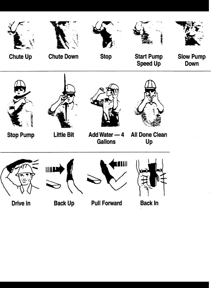
IMPORTANT HAND SIGNALS
C-30HD — PARTS & OPERATION MANUAL — REV. #4 (03/06/01) — PAGE 9

The following operating principles and operating suggestions should prove helpful in the successful operation of your concrete pump.Your new “small line” concrete pump has been designed to give you many years of service when operated properly. A study of the following paragraphs is important to the successful operation of your new Direct-flo Concrete Placer.
All concrete pumps require a high level of operator skill and more frequent service than most of the other construction equipment. The highly abrasive nature of concrete under pressure makes it extremely important that expendable wear components be inspected at regular intervals between jobs to prevent having to replace these items during a pour. Experience has proved that inconsistency of batched concrete mixes and frequent moving of the line requires the operator to be readily available at all times during pumping to stop the pump and prevent abuse to the unit which may occur if unexpected blockages develop.
PUMP MIX GUIDELINES
When ordering concrete, be certain to advise the concrete supplier that you require a “pump mix”.The Direct-flo manifold will pump a wide variety of materials, but certain basic principles must be followed to assure successful pumping, as follows:
1. Generally speaking, the washed concrete sand and #4 aggregate (pea gravel) should conform to A.S.T.M. standards in regard to sieve analysis. Sands in some areas are washed clean of the #100 and #200 mesh fines, which results in separation and jamming in the manifold while pumping under pressure. If this condition develops, check with your concrete suppliers engineers and get their recommendations for supplementing the lack of the fines.The use of locally accepted ad-mixs may be required. (For example, Pozzolith, Bentonite Clay, Plastiments, etc.) When properly prescribed, additives form the plastic paste sometimes necessary to hold the cement and aggregate together. NOTE: If jamming conditions in the pump or hose occur for any reason at all, do not attempt to use more power to correct the condition. Determine the cause of jamming, correct it and resume pumping. Trying to force material through under jammed conditions may result in damage to the drive system, thus voiding any warranty services.
GENERAL INFORMATION
2.As a general rule, the use of approximately six sacks of cement, 70% washed concrete sand and 30% #4 pea gravel per yard of concrete will result in a pumpable mix. The ideal nature of sand and rock in certain areas may permit you to increase the percentage of rock or adjust the mix considerably to meet the job requirements. When possible, you may experiment with various mixes in your area to determine the degree of versatility of the Direct-flo Pump.
3.Uniform gradition of the washed concrete sand and the 1/2” minus aggregate along with sufficient cement content and water are important to a successful pump operation.
4.A recommended pumpable mix design would be 70% sand and 30% aggregate-cement content to be a minimum of 6 sacks. (564 lbs.)
NOTE; Your local sand and rock engineers will give you the s.s.d. weights of sand and rock required in your local area which will yield one cubic yard per the above recommendation.
SAMPLE DESIGN MIX
6 1/2 sacks cement (611 lbs.)
1800 lbs. washed concrete sand
1000 lbs. pea gravel
230 lbs. water
5.Test laboratory data has proven in many areas that the above mix guidelines have produced concrete rated at 3000 psi (28 day test) and upwards of 5000 psi with an increase in cement.
6.In some areas where the gradation of sand and rock is ideal and sufficient cement is used along with admixtures, the Mayco small line concrete pump will handle up to a 50-50 ratio of sand and rock.
7.When the mix is designed for wet gunning applications, it is normal to increase the cement (up to 7.5 or 8 sacks) and change the sand to rock ratio to 85% sand and 15% rock.
8.The Mayco concrete pump will valve efficiently when using cellular-foam concrete mixes upwards of 70 lbs. per cubic foot wet density. (Below 70 lbs. materials (roof decks) the valving becomes inefficient.)
PAGE 10 — C-30HD — PARTS & OPERATION MANUAL — REV. #4 (03/06/01)
NOTE PAGE
C-30HD — PARTS & OPERATION MANUAL — REV. #4 (03/06/01) — PAGE 11

The Mayco concrete pump has one main pumping piston which is valved by means of two ball checks. (A inlet, and B outlet.)
The secondary piston is used as a compensator piston to smooth out the pulsations of a single piston action. Note: The compensator will not start operating until material is pumped into the line and back pressure develops.
The compensator spring, which is installed on the compensator piston rod, deflects with each piston stroke.This “spring cushion”, in conjunction with the cam profile, produces and uninterrupted smooth flow of material under average pumping conditions.
An automatic, centrifugal clutch is installed to engage and disengage the pumping action without stopping or starting the engine. The centrifugal clutch is set at 1100 R.P.M. release. The engine idle speed is approximately 750 R.P.M.; therefore, the clutch is completely disengaged at idle.The throttle settings while pumping should always maintain an engine R.P.M. high enough to prevent the clutch from slipping and burning the clutch lining.
C-30HD — HOW IT WORKS
The return spring which is installed on the rocker arm, is installed to eliminate shock and stress between the cam roller and the cam weldment when the pump is in operation. If the return spring is removed or replaced for any reason, maintain the backing plate dimension of 3” as shown on Figure 3, to produce the proper pre-loading of the spring for a smooth performance.
Figure 1- The pumping cylinder retracts drawing the material past the ball (A) and filling the cylinder.The compensator piston is pumping the material out to the nozzle and causing ball (B) to seat preventing the material from returning to the pumping cylinder intake.
Figure 2- The pumping piston is forcing the material past ball
(B) and out to the nozzle, also seating ball A so that the material will not flow back to the hopper. This action also fills the compensating piston for the next stroke.
Figure 3- Shows the relationship between the return spring, the compensator spring and the rocker arm to maintain a smooth performance. Do not tighten the bolt (Item 1) completely, the rod end must be able to move.
PAGE 12 — C-30HD — PARTS & OPERATION MANUAL — REV. #4 (03/06/01)

C-30HD — HOW IT WORKS
C-30HD — PARTS & OPERATION MANUAL — REV. #4 (03/06/01) — PAGE 13
OPERATING SUGGESTIONS
1.A well-planned location of the pump and routing of the hose before starting a pour may save subsequent moves throughout the job.
2.Before concrete is discharged into the hopper, it is suggested that 3 to 4 gallons of water be sprayed into the hopper, followed by approximately 5 gallons of a creamy cement and water slurry (1/2 bag of cement to 5 gallons of water). This procedure lubricates the hose and prevents separation and blockages in the hose. Note: Getting the concrete to flow through the hose at the start of the pumping cycle can be one of the most critical operations of the pour. (Manually operate the throttle - when starting. NOT REMOTELY)
3.It is important that once the slurry procedure is completed, and you have started concrete flowing through the hose, do not stop the pour until all the slurry is pumped out and the concrete has reached the end of the hose. The only time to stop the pump at the start is if a blockage occurs.
4.When the pump is stopped for any reason during a pour; e.g., moving hose, waiting for redi-mix truck, the following suggestions are offered:
A.Leave the hopper full of concrete at the time of shutdown. It is important not to let the redi-mix driver wash too much water into the hopper, as this could cause separation of the concrete in the hopper.
B.If the shutdown period exceeds 2 to 3 minutes, turn off the engine so the vibration does not separate the mix in the hopper which can cause a blockage in the manifold when the pump is started.
C.If it is necessary to wait 10 minutes or more for another load of concrete, it is wise to start the pump and pump 6 or 8 strokes every 5 minutes to prevent setting of the mix in the system. If waiting time is excessive, it would be wise to wash out the pump and hoses and start over when the new truck arrives.
D.When pumping stiff mixes and there is waiting time between redi-mix trucks, it is advisable to add some water to the last hopper of material and “hand mix” to ensure an easier start with the following load.
C-30HD OPERATING INFORMATION
E.When the pumping job requires a stiffer mix, the following method is suggested for starting: Take a water hose with a nozzle on it and apply water with a fine spray to the concrete as it comes down the redi-mix chute into the pump hopper after the slurry procedure is completed and you are ready to start pumping. Using this procedure will make it easier to pump through the clean hose. Note: Once the concrete has reached the end of the hose, do not apply any more water in this manner as this procedure is used on the start only.
F.Hose sizing is very important: We strongly recommend on harsh mixes, vertical pushes, stiff concrete, shotcrete, long pushes, that a 2 1/2” line be used as far as possible. The advantages of using the 2 1/2” line are improved pumpability, less pumping pressure and less wear on the pump.
5.Following the pump operation, proper wash out of all materials or “build-up” within the pump manifold and hoses will prevent problems when starting the next job.
6.A thorough inspection of the drive components and greasing of all bearings after each job will ensure adequate lubrication and service to the pump which is normally operating in wet, gritty conditions. Note: Over-greasing any bearing on your Mayco pump will not damage the bearing.
7.Warning: Common sense tells us that if you drive a truck into a brick wall, something is going to be damaged.The same holds true with your concrete pump. If you repeatedly
pull the throttle all the way out and try to force your pump to push through blockages due to separation of material in the hose or manifold, you will soon have breakdowns and costly repairs which are not covered under warranty.If a blockage occurs, find where it is and clear it before further pumping. Do not use horse-power; it will only make it worse.
8. Warning: It will be necessary at times to move your pump from one job site location to another. Before moving the pump, make sure to pump the remaining concrete out of the hopper. Moving the pump with a full
hopper of concrete can cause severe damage or breakage of the axle and axle springs, excess strain and pressure on the hub and bearing assembly.
PAGE 14 — C-30HD — PARTS & OPERATION MANUAL — REV. #4 (03/06/01)

PUMPINGTIPS ANDTROUBLE SHOOTING
1.The effects of heat and excessive time on concrete: Hot concrete, commonly referred to as a hot load, is concrete that has been in the redi-mix truck in excess of 2 to 3 hours. On a hot day, this amount of time is even less. A brief explanation of why heat and time affect concrete: Concrete starts setting by drying up through a chemical reaction.The catalyst to this reaction is heat.When pumping a hot load, it is important to remember that when you have to stop pumping for any reason, add water to the concrete in the hopper and hand mix and move concrete in the hose every 5 minutes. If the shut down time becomes too long, wash out immediately.
2.ADMIXTURES: A remixtures that are designed into the concrete mix by the redi-mix company or an architectural engineering company. This section lists common admixtures and a brief explanation of their function.
A.POZZOLITH 300 R or the equivalent acts as a water retarder and a lubricant. On a lean mix, long pushes, stiff mixes, and vertical pushes, Pozzolith 300 R helps pumpability.
B.MBVR, air entraining, acts as a lubricant.
C.CALCIUM CHLORIDE, commonly referred to as C.C., is used as an accelerator. When pumping a load with calcium chloride, it is recommended that you wash out if the waiting time between delivery trucks becomes too long.
D.SUPER PLASTICIZERS, acts as an accelerator.The concrete will look very wet after the super plasticizer is added, but will begin to set up very fast. Wash out immediately if you do not have a truck waiting. Super plasticizers are used mainly on commercial jobs.
E.RED LABEL, acts as a water retarder and an accelerator. Red label will be used mainly on commercial jobs.
F.FLY ASH, is used to help increase the strength of the concrete and decrease the cement content per yard. This is one of the most common admixtures used.
NOTE: All admixtures will be shown on the redi-mix concrete ticket. Before starting the pumping job, ask the driver of the redi-mix truck to see the concrete ticket and note the admixtures that exist and take the proper action.
3.When pumping long distance or pumping stiff mixes, you can expect a drop in volume compared to shorter lines and wetter mixes due to the change in valve efficiency or cavitation.
4.Leaking manifold seals or hose coupling gaskets which leak water can cause separation and subsequent jamming at that point.
C-30HD OPERATING INFORMATION
5.Damaged hoses with internal restrictions can cause blockages.
6.If a blockage occurs in a hose, “walk the hose” until you find the point of trouble.The hose will be soft immediately past the blockage. If this happens at the start, disconnect the hose at the first coupling past the blockage. Elevate the hose at that point with the blockage area hanging down. Note: Use extreme care! The hose line is under pressure and can cause serious injury. Using a hammer, you can pound the down-stream edge of the packed area until it is free to flow. Shake all of the sand and gravel out to the end of the hose. Before reconnecting the hose, start the pump and run a small amount of concrete out to the end of the hose.This will assure that all of the separation is out of the hose.
7.The manifold is plugged if the volume at the discharge end of the hose stops, and the hose is soft. The drive belts will start to slip and the engine will lugdown.
To clear a plugged manifold, great care must be taken as a dangerous condition will exist due to pressure build-up inside the manifold.
Follow these instructions carefully:
7.1Stop the pump. Switch off the engine.
7.2DO NOT open any of the delivery system joint clamps.
7.3The senior experienced operator must warn all others to stand at least 20 feet away from the machine and turn their heads away from the manifold.
7.4The operator must position himself/herself away from the hinged side of the manifold.
7.5Wearing safety glasses, grasp the clamp arm weldment and carefully pull it open to the primary (safety) position. STOP count to 20. This will allow the pressure to release.
7.6After the pressure has been released, open the clamp arm weldment and swing the hinged discharge cone open.
7.7Remove blockage with around a 2-foot length of reinforcing steel rod. Flush the manifolds with water. Make sure the (3” x 2”) reducer is clear of any blockage before closing the discharge cone.
7.8After the blockage has been cleared and the pump manifold has been thoroughly flushed with water, close the hinged discharged cone and lock into place.
7.9Before reconnecting hose to the reducer, start the engine and pump two or three shovels of concrete through the reducer.This will insure that all the blockage has been cleared.
C-30HD — PARTS & OPERATION MANUAL — REV. #4 (03/06/01) — PAGE 15

7.10 Shake out around 2 feet of concrete before reconnecting hose to pump. After this is done, connect hose to pump and resume the pumping operation.
8. If it is necessary to wait 1/2 hour or more for another load of concrete, it is advisable to consider the factors affecting the concrete that is already in the pump and system. To prevent setting of the mix in the system: 1) how old is the concrete ? 2) is there an accelerator, calcium chloride, red label, etc., in the concrete ? 3) the temperature of the day, 80, 90, degrees? 4) how much system you have out and how stiff was the mix you were pumping? If, for any reason, the mix should set up in the system, the following procedure is suggested:
Note: Use extreme care! The hose is under pressure!
Disconnect the hose from the pump and wash the pump out immediately. Reconnect the hose and fill the hopper with water. DO NOT try to push all the concrete out of all of the hose line at one time. For example: If you had 200 ft. of system out, you would disconnect each hose. Clean it out by pushing water through the first hose off the pump, then continue progressing through all the hoses, until all the system is clean. If waiting time is excessive, it would be wise to wash out the pump and hoses and start over when the new truck arrives. This can be avoided by being attentative to the pump and system, also taking into consideration the above 4 factors affecting the mix.
9.“Down-hill pumping” can be difficult on some jobs.The slurry procedure would be the same as explained on the pages titled Operating Suggestions. It is suggested that a sponge 2”x 4”x 6” be placed in the hose before the start of pumping. Wet the sponge before placing it in the hose. The reason for using the wet sponge is to keep the slurry from running too far ahead of the concrete and so reducing the possibility of separation. When the pump is stopped, the material can flow slowly down, due to gravity, and cause the hose to collapse.When pumping is resumed, you can expect a blockage at the point of hose collapse. To prevent this from happening, the hose can be “kinked off” at the discharge end when the pump is stopped to prevent the gravity flow of the material in the hose.The use of stiffer mixes when pumping down-hill will decrease gravity flow of the material in the hose and will assure a smoother operation between the cam roller bearing and cam plate. As with any job, make sure that the hose and the couplings are in good workable shape.
C-30HD OPERATING INFORMATION
10. When pumping vertically:
A.When pumping vertically up the side of a building, above 40 feet, we would recommend the installation of steel pipe securely fastened at intervals as necessary to support the pipe. Ninety degree, long radius pipe sweeps should be installed at the top and bottom of the steel line. Use a 25 ft. hose, or short section, off the pump; and for the balance of the horizontal distance to the vertical line, use steal pipe.This type of installation has been satisfactory on many jobs being pumped in excess of 100 feet high. Line pressures are always less using steel pipe as compared to hose.
B.When pumping vertically, using all hose, it is recommended not to go higher than 50 feet with hose. The hose should be tied off at intervals of 10 feet, if possible. Special attention should be given when tieing the hose off at the top as the hose will have a tendency to stretch when filled with concrete. This will increase the possibility of a blockage at the point where the hose is tied off. To avoid this, a long radius of 90 degree elbow is recommended. The suggested place to tie off is on the hose, under the clamp. Note: It is strongly recommended that pipe be used on all vertical pumping for safety and convenience.
If it is absolutely necessary to use hose, then use this section as a guide.
11. If the volume at the end of hose starts to decrease gradually and eventually almost stops, it is quite likely that the valve seats have had excessive wear and need replacement. Once they have reached a certain wear point, they may “channel out” rapidly and material will reciprocate past the ball on each stroke.The hollow steel ball should be replaced when it starts to show dents or appears to be badly worn. Sand and aggregate materials in some areas are extremely sharp and hard and therefore highly abrasive. Under these conditions when pumping stiff mixes, or to high elevations which cause line pressures, it will be noted that valve components may have short wear life. If this condition exists, it is advisable to remove the manifold only, and inspect the lower seat at the end of each day. If it appears that the seat is beginning to “channel out, replace before starting the next day’s pour. The upper valve seat can be inspected after each washout by running your finger around lower edge of seat where the ball makes contact.You can reach this from the inside of the hopper. Be sure that the engine is turned off.
PAGE 16 — C-30HD — PARTS & OPERATION MANUAL — REV. #4 (03/06/01)

12. Slight pulsation of the hose will always be noticeable near the pump. Excessive pulsation of the hose near the pump is normally due to higher than average line pressures caused by stiff, harsh mixes, or extremely long pumping distances. The use of 2 1/2” I.D. hose in these extreme cases reduces line pressures or the addition of slight amounts of water to the mix, if permissible, will permit easier pumping. The use of certain pumping admixtures may help.
If excessive pulsation exists in the hose, it is advisable to use burlap or some means of wear protection under the hose at points where the hose may wear through the outer cover; e.g. over forms, steel or sharp curbs.
13.If the cam roller does not ride on the cam profile smoothly, it may be caused by insufficient line back-pressure; e.g., a wet mix with only 50 feet of hose. Add more hose as necessary. It can also be caused by cavitation or the passing of oversized aggregates through the valving, causing it to skip.
14.When using Snap-Joint couplings with gaskets to join hose, see that they are washed clean after each job. Keeping the hose ends clean (heavy duty) is very important for the best job setup. A thin coat of grease on the rubber gasket or dipping both coupling and gasket in water before coupling the hose will make for easier installation.
15.All new pumps are “water pressure tested” at the factory before shipment.This procedure permits a thorough inspection of entire drive system and valving under simulated full load conditions. The pump owner can do the same by attaching an adaptor to couple to the end of the discharge cone; e.g., the use of a standard 2” pipe cap with a 3/8” hole drilled in the center , screwed on to the end of the hinged cone or reducer at the pump. Fill the hopper with water after making sure that all sand and rock have been removed from the manifold. Operate the pump at full throttle and the 3/8” diameter hole restriction will create sufficient back-pressure to make a thorough inspection of all moving parts.
16.Before starting the pumping operation, the following check list procedure should be followed:
1.Check the engine oil.
2.Check the oil reservoir of the lubrication system to make sure that it is full.
3.Inspect the chain and belt adjustment.
4.Check the cam oiler.
5.Start and run the engine a minimum of five minutes before starting the pumping operation.
Note: When the redi-mix truck arrives, it is always a good idea to check the concrete ticket and make sure you have the proper mix design.
C-30HD OPERATING INFORMATION
CLEAN UP PROCEDURE
PART A
1.Ensure that there is no blockage in the hose and line (See Page 15, Para. 6) or in the manifold (See Page 15, Para. 7). If a blockage exists, clear it as it dictates how the machine will pump the next time it is used. At the end of every pour, or because of long delays during a pour, the pump and delivery system must be thoroughly cleaned by removing all concrete material.
2.Proper wash out of all materials or build up within the pump manifold and hoses following the pumping operation will prevent problems when starting the next job. After completion of the pour, pump the remaining concrete in the hopper through the discharge line.
3.Note:To avoid the possibility of separation during clean-up, do not pump the concrete below the inlet ball in the hopper. It is best to leave approximately 3 to 4 inches of concrete above the inlet ball.
4.Turn the pump engine off before filling the hopper with water. Engine vibration at idle may “separate” material in the hopper, causing jamming in manifold when pumping is resumed.
5.Fill hopper with water and resume pumping. The water will push the concrete through the line.When the water runs clear at the end of the hose, disconnect lines and shake out all the sand and sediment so the lines will be clean for the next pour.
6.It is important that the hinged discharge cone on the pump manifold be opened and all remaining concrete (rock and sand) be thoroughly washed out.This must be done after each job to prevent concrete build up in the discharge manifolds and 3” discharge elbow.
C-30HD — PARTS & OPERATION MANUAL — REV. #4 (03/06/01) — PAGE 17
C-30HD OPERATING INFORMATION
PART B
This section will explain the recommended procedure for using a sponge to clean out the lines. After completion of the pour, pump the remaining concrete in the hopper through the discharge line. Using a shovel, clean the sides of the hopper. (Note: The pump engine should be turned off, as explained in Part A of the Clean Up Procedure.) After the sides of the hopper have been cleaned, add a small amount of water to the remaining concrete in the hopper and hand mix.
Start the pump engine and pump the hopper all the way down. Disconnect the hose from the pump. Fill the hopper with water and pump the remaining concrete out of the pump. Open the hinged discharge cone and thoroughly wash out all remaining concrete (sand-sediment) from the cone and pump manifolds. Close the discharge cone and lock in place. Take a sponge (2”x 4”x 6”) and soak it with water. Take the hose that is disconnected from the pump and shake out the concrete so that about 2 feet of it is clear. Insert the sponge into the hose. Reconnect the hose to the pump. Fill the hopper with water and resume pumping. Run the pump approximately half throttle. The sponge will be discharged at the end of the line followed by clear water. At this point, the pump and lines will be completely clean and ready for the next job.
WARNINGS
1.Never put your hands, or any other parts of your body, in the hopper when the engine is running.
2.Never use muriatic acid to clear the pump. Acid will dissolve the chrome finish on the pumping cylinder.
3.When using a clean-out hook to clean out back into the redi-mix truck, use a safety chain to secure the clean-out hook to some solid part of the redi-mix truck to prevent the hook from jumping off the redi-mix truck’s hopper. Run the pump at half throttle.
4.Never use air to clean out the lines.
Always think safety first!
PAGE 18 — C-30HD — PARTS & OPERATION MANUAL — REV. #4 (03/06/01)

CONCRETE MIX DESIGNS-SCREEN ANALYSISTERMINOLOGY
The following information has been prepared to assist in the selection of concrete mix designs in certain areas where the use of concrete pumps is a new industry.
The result of years of experience by many concrete pump users and aggregate suppliers has proven the importance of certain requirements necessary to successful concrete pumping. The strength and quality of the concrete is relative to the cement/water ratio and the type of gradation of the aggregates used.
Special emphasis is given to the gradation of the fine aggregates, coarse aggregates sand and used in all pump mixes. Generally speaking, if the screen analysis of the local sand and rock conform to the A.S.T.M. specifications shown on Pages and 13 and the proper ratio of sand and rock are used in the mix, you can expect a pumpable mix.
If difficulty is experienced in pumping the mixes shown on Pages 11 and 12, consult your local aggregate supplier with this information and make the necessary adjustments.
CONCRETE MIX INFORMATION
DEFINITIONS
ONE SACK CEMENT (U.S.)-94lbs. (42.58 KG)
S.S.D.-Saturated Surface Dry: Meaning sand particles may be saturated with moisture but there is no free water on the surface.
OVEN DRY-meaning all the moisture is removed from the sand particle.
SLUMP-a measure of moisture consistency.
W/C SAND-washed concrete sand.
#4 GRAVEL or ROCK-3/8” PEA GRAVEL (1/2” MINUS)
#3 GRAVEL or ROCK-3/4” rock (1” minus)
POZZOLITH-Master Builders Admixture -(Pozz)
P.S.I.-compressive strength (Pounds per Square Inch)
DEFICIENCIES IN SIEVE ANALYSIS of AGGREGATES
The uniform gradation of sand and aggregate in the concrete mix is extremely important in all pumping operations. It is highly possible that the lack of certain sieve sizes may prevent pumpability. In some areas it may be necessary to make up these deficiencies by the addition of “blending sands” to the local sand.
GENERAL RULE-supplement to improve pumpability.
FLY ASH-use up to 15% of cement weight.
POZZOLIN-use up to 13% of cement weight.
C-30HD — PARTS & OPERATION MANUAL — REV. #4 (03/06/01) — PAGE 19

CONCRETE MIX INFORMATION
The following information has been extracted from actual testing laboratory reports. The purpose of this printing is only to help create a better understanding of the importance of uniform gradation and proportioning of materials which affect pumpability of concrete mixes.These weights and proportions illustrate that when the sieve analysis is ideal, the sand/rock ratio can be adjusted (65% sand 35% rock) and pumpability should be excellent.
EXAMPLE #1 (A California Test Lab. Report)
JOB: Building Foundations (Water Project)
Sacks per cu./yd. |
6.5 designed for 2,500 lbs. in 28 days |
Gallons per sack |
7.1 |
Washed Sand-#200 wash |
1.3 |
Organic matter-OK |
|
Specific gravity (SSD) |
Sand-2.58; Pea Gravel-2.60 |
Sieve analysis-percent passing |
|
|
|
|
|
|
|
|
|
|
Material |
1.5” 1” |
3/4” |
3/8” |
#4 |
#8 |
#16 |
#30 |
#50 |
#100 |
#200 |
W.C. Sand |
|
|
100 |
99.7 |
79.1 |
60.4 |
36.5 |
14.3 |
4.0 |
1.1 |
Pea Gravel |
|
|
100 |
3.0 |
|
|
|
|
|
|
% Comb. |
|
|
100 |
66 |
51 |
39 |
23 |
9 |
3 |
1.0 |
DESIGN FOR ONEYARD OF CONCRETE (SATURATED & SURFACE DRY):
Absolute volume of aggregate in one cu. yard: |
17.78 cu. ft. |
Specific gravity of aggregates in one cu. yard: |
2.58 |
Weight of aggregates in one cu. yard batch: |
2850 lbs. |
|
% |
BATCH |
SPEC.GRAVITY |
ABS.VOL. |
W.C. Sand |
65 |
1800 |
2.58 |
11.56 |
PEA GRAVEL |
35 |
1000 |
2.60 |
6.22 |
WATER 46 gal. |
|
1 |
|
|
CEMENT 6.5 sk. |
|
611 |
|
|
TOTAL |
|
|
|
27.00 |
ADMIXTURE: |
|
None |
|
|
SLUMP |
|
4” |
|
|
REMARKS |
|
This mix designed for pumping |
|
|
NOTE: |
|
Due to the availability of well-graded sand as shown in the above sieve analysis, |
||
|
|
this mix pumped very successfully. |
|
|
PAGE 20 — C-30HD — PARTS & OPERATION MANUAL — REV. #4 (03/06/01)
A.S.T.M. STANDARD SPECIFICATION FOR GRADING AGGREGATE
Screen |
Size of Operating |
|
|
Percentage Passing |
|
U.S. |
|
Metric |
(by weight) |
|
|
|
|
|
FINE AGGREGATE: Referred to as washed concrete sand. |
|
|
||
|
|
|
|
|
3/8” |
3/8” |
|
9.51mm |
100% |
#4 |
4760 micron |
|
4.76 mm |
95 to 100% |
#8 |
2380 micron |
|
2.38 mm |
80 to 100% |
#16 |
1190 micron |
|
1.19 mm |
50 to 85% |
#30 |
590 micron |
|
1.19 mm |
50 to 85% |
#50 |
297 micron |
|
297 µ |
10 to 30% |
#100 |
149 micron |
|
149 µ |
2 to 10% |
|
|
|
|
|
3/8”(9.51 mm) PEA GRAVEL AGGREGATE: Referenced to as #4 Rock or Gravel or 1/2”minus (12.7 mm) size.
1/2” |
1/2” |
12.7 mm |
100% |
3/8” |
3/8” |
9.51 mm |
85 to 100% |
#4 |
4760 micron |
4.76 mm |
10 to 30% |
#8 |
2380 micron |
2.38 mm |
0 to 10% |
#16 |
1190 micron |
1.19 mm |
0 to 5% |
|
|
|
|
C-30HD — PARTS & OPERATION MANUAL — REV. #4 (03/06/01) — PAGE 21

CONCRETE MIX INFORMATION
Consolidated Rock Products Co., Division of Tests |
|
|
|
|
|
|
||
3/8” Pea Gravel STANDARD PUMP MIXES (one-half inch minus) |
|
|
|
|
||||
NOTE: All weights shown are one cubic yard with S.S.D. aggregates. |
|
|
|
|
||||
CRP Mix Number |
6004 |
.......................... |
6005 |
............................. |
6006 |
.......................... |
6007 |
|
Design Slump (in.) |
6” |
(15 cm) ............. |
6” |
(15 cm) ................. |
6” |
(15 cm) ............. |
6” |
(15 cm) |
Cement, SACK. |
7.0 ................................ |
|
7.0 ...................................... |
|
7.0 ................................ |
|
7.0 |
|
Cement, Lbs. |
658 |
(298 kg) ............ |
658 |
(298 kg) ................ |
658 |
(298 kg) ............ |
658 |
(298 kg) |
w/Con Sand (1 lb.) |
2031 |
(920 kg) ............ |
2982 |
(943 kg) ................ |
1879 |
(851 kg) ............ |
1943 |
(880 kg) |
Gravel #4(9.51 mm) |
677 |
(307 kg) ............ |
693 |
(314 kg) ................ |
806 |
(365 kg) ............ |
832 |
(377 kg) |
TOTAL AGGREGATE |
2708 |
(1227 kg) .......... |
2775 |
(1257 kg) ............. |
2685 |
(1216 kg) .......... |
2775 |
(1257 kg) |
ADMIXTURE |
|
|
|
|
|
|
|
|
Pozzolight 311-1 lb. |
1.4 |
(.63 kg) ............. |
1.4 |
(.63 kg) ................. |
1.4 |
(.63 kg) ............. |
— |
|
Water, Design (gals.) |
50.0 |
(189 liters) ......... |
53.0 |
(200 liters) ............ |
50.0 |
(189 liters) ......... |
53.9 |
(200 liters) |
Mater, Max. (gals.) |
50.0 |
(189 liters) ......... |
53.0 |
(200 liters) ............ |
53.0 |
(200 liters) ......... |
53.0 |
(200 liters) |
NOTE: Multiply above kilograms and liters by 1.308 to obtain the proportions for one cubic meter of concrete.
Consolidated Rock Products Co., Division of Tests |
|
|
|
|
|
|
||
3/8” Pea Gravel STANDARD PUMP MIXES (one-half inch minus) |
|
|
|
|
||||
NOTE: All weights shown are one cubic yard with S.S.D. aggregates. |
|
|
|
|
||||
CRP Mix Number |
6000 |
.......................... |
6001 |
............................. |
6002 |
.......................... |
6003 |
|
Design Slump (in.) |
6” |
(15 cm) ............. |
6” |
(15 cm) ................. |
6” |
(15 cm) ............. |
6” |
(15 cm) |
Cement, SACK. |
6.5 ................................ |
|
6.5 ...................................... |
|
6.5 ................................ |
|
6.5 |
|
Cement. Lbs. |
611 |
(276 kg) ........... |
611 |
(276 kg) ................ |
611 |
(276 kg) ............ |
611 |
(276 kg) |
w/Con Sand (1.1 lb.) |
2062 |
(934 kg) ........... |
2112 |
(957 kg) ................ |
1924 |
(872 kg) ............ |
1971 |
(893 kg) |
Gravel #4 (9.51mm) |
687 |
(311 kg) ........... |
704 |
(319 kg) ................ |
825 |
(374 kg) ............ |
845 |
(383 kg) |
TOTAL AGGREGATE |
2749 |
(1245 kg) .......... |
2816 |
(1276 kg) ............. |
2749 |
(1245 kg) .......... |
2816 |
(1276 kg) |
ADMIXTURE |
|
|
|
|
|
|
|
|
Pozzolight 311-1.3lb. |
1.3 |
(.59 kg) ............. |
1.3 |
(.59) ...................... |
— |
|
|
|
Water, Design (gals.) |
50.0 |
(189 liters) ......... |
53.0 |
(200 liters) ............ |
50.0 |
(189 liters) ......... |
53.9 |
(200 liters) |
Mater, Max. (gals.) |
50.0 |
(189 liters) ......... |
53.0 |
(200 liters) ............ |
53.0 |
(200 liters) ......... |
53.0 |
(200 liters) |
NOTE: Multiply above kilograms and liters by 1.308 to obtain the proportions for one cubic meter of concrete.
PAGE 22 — C-30HD — PARTS & OPERATION MANUAL — REV. #4 (03/06/01)

SLUMPTEST PROCEDURE
1.To obtain a representative sample, take samples at three or more regular intervals throughout the discharge of the mixer or truck. DO NOT take samples at the beginning or end of the discharge.
2.Dampen the inside of the cone and place it on a smooth, moist, nonabsorbent, level surface large enough to accommodate both the slumped concrete and the slump cone. Stand on the “foot pieces” throughout the test procedure to hold the cone firmly in place.
3.Fill the cone 1/3 full by volume and rod 25 times with a 1/2” dia x 24” lg. bullet-pointed steel rod. (This is a specific requirement which will produce non-standard results unless followed exactly.) Distribute rodding evenly over the entire cross section of the sample. (See figure A.)
4.Fill cone another 1/3 which will make the cone 2/3 full by volume. Rod this second layer 25 times with the rod penetrating into, but not through, the first layer. Distribute rodding evenly over the entire cross section of the layer. (See figure B.)
5.Fill cone to overflowing. Rod this layer 25 times with rod penetrating into but not through, the second layer. Distribute rodding evenly over the entire cross section of this layer. (See figure C.)
6.Remove the excess concrete from the top of the cone, using the tamping rod as a screed. (See figure D.)
7.Lift the cone vertically with a slow even motion. Do not jar the concrete or tilt the cone during this process. (See figure E.) Invert the withdrawn cone, and place it next to, but not touching the slumped concrete.
8.Lay a straight edge across the top of the slumped cone. Measure the amount of slump in inches from the bottom of the straight edge to the top of the slumped concrete at a point over the original center of the base (See Figure F).The slump operation must be complete in a maximum elapsed time of 1- 1/2 minutes. Discard the concrete. DO NOT use it in any other tests.
C-30HD — PARTS & OPERATION MANUAL — REV. #4 (03/06/01) — PAGE 23
EXPLANATION OF CODE IN REMARKS COLUMN
How to read the marks and remarks used in this parts book.
Items Found In the “Remarks” Column
Serial Numbers-Where indicated, this indicates a serial number range (inclusive) where a particular part is used.
Model Number-Where indicated, this shows that the corresponding part is utilized only with this specific model number or model number variant.
Items Found In the “Items Number” Column
All parts with same symbol in the number column, *, #, +, %, or ■, belong to the same assembly or kit
NOTE
If more than one of the same reference number is listed, the last one listed indicates newest (or latest) part available.
NOTE
The contents of this catalog are subject to change without notice.
PAGE 24 — C-30HD — PARTS & OPERATION MANUAL — REV. #4 (03/06/01)

C-30HD SUGGESTED SPARE PARTS
C-30HD Concrete Pump
|
1 Units |
|
Qty. |
P/N |
Description |
6 ...... |
EM14904 ..................... |
PISTON CUP KITS |
4 ...... |
EM18804 ..................... |
4 1/2" STEEL BALL |
4 ...... |
EM14818 ..................... |
4" STEEL BALL |
6 ...... |
EM14903 ..................... |
BALL STOP PIN KIT |
10 ...... |
EM18801 ..................... |
0-RING MANIFOLD |
1 ...... |
EM14308 ..................... |
CHAIN |
2 ...... |
EM26313 ..................... |
HALF LINK |
2 ...... |
EM26314 ..................... |
MASTER LINK |
1 ...... |
EM14334 ..................... |
COMPENSATOR SPRING |
2 ...... |
EM14408 ..................... |
BRONZE RING |
2 ...... |
EM903092 ................... |
CAM ROLLER BEARING |
2 ...... |
EM14315 ..................... |
V-BELT |
2 ...... |
EM14842 ..................... |
LOWER SEAT |
2 ...... |
EM14843 ..................... |
UPPER SEAT |
2 ...... |
EM26310 ..................... |
CLUTCH LINING |
10 ...... |
EM18409 ..................... |
O-RING |
2 ...... |
EM20763 ..................... |
FUEL FILTER |
2 ...... |
EM26746 ..................... |
OIL FILTER |
2 ...... |
EM20328TKIT ............. |
BEARING KIT |
1 ...... |
EM28004DD ................ |
REDUCER 3" X 2" |
1 ...... |
EM23946 ..................... |
3" ELBOW |
2 ...... |
EM28904 ..................... |
3" CLAMP |
4 ...... |
EM28904-1 .................. |
3" GASKETS |
1 ...... |
EM14159 ..................... |
HOPPER SCREEN |
1 ...... |
EM14401 ..................... |
OIL PUMP |
1 ...... |
EM20709 ..................... |
SOLENOID |
2 ...... |
EM2074 ........................ |
THROTTLE LINKAGE |
NOTE
Part number on this Suggested Spare Parts List may super cede/ replace the P/N shown in the text pages of this book.
C-30HD Concrete Pump
|
3 Units |
|
Qty. |
P/N |
Description |
10 ...... |
EM14904 ..................... |
PISTON CUP KITS |
10 ...... |
EM18804 ..................... |
4 1/2" STEEL |
10 ...... |
EM14818 ..................... |
4" STEEL BALL |
12 ...... |
EM14903 ..................... |
BALL STOP PIN KITS |
25 ...... |
EM18801 ..................... |
MANIFOLD O-RINGS |
3 ...... |
EM14308 ..................... |
CHAINS |
10 ...... |
EM26313 ..................... |
HALF LINK |
10 ...... |
EM26314 ..................... |
MASTER LINK |
2 ...... |
EM14334 ..................... |
COMPENSATOR SPRING |
4 ...... |
EM14408 ..................... |
BRONZE RING |
2 ...... |
EM903092 ................... |
CAM ROLLER BEARING |
4 ...... |
EM14315 ..................... |
V-BELT |
6 ...... |
EM14842 ..................... |
LOWER SEAT |
6 ...... |
EM14843 ..................... |
UPPER SEAT |
3 ...... |
EM26310 ..................... |
CLUTCH LINING |
20 ...... |
EM18409 ..................... |
O-RING |
3 ...... |
EM207063 ................... |
FUEL FILTER |
3 ...... |
EM26746 ..................... |
OIL FILTER |
2 ...... |
EM20328TKIT ............. |
BEARING KIT |
2 ...... |
EM28004DD ................ |
REDUCER 3" x 2" |
2 ...... |
EM23946 ..................... |
3" ELBOW |
4 ...... |
EM28904 ..................... |
3" CLAMP |
10 ...... |
EM28904-1 .................. |
3" GASKET |
2 ...... |
EM14159 ..................... |
HOPPER SCREEN |
2 ...... |
EM14401 ..................... |
OIL PUMP |
2 ...... |
EM20709 ..................... |
SOLENOID |
4 ...... |
EM20714 ..................... |
THROTTLE LINKAGE |
1 ...... |
EM14300 ..................... |
CAM |
1 ...... |
EM14801 ..................... |
T-MANIFOLD |
1 ...... |
EM14819 ..................... |
Y-MANIFOLD |
2 ...... |
EM14335 ..................... |
PISTON ROD |
1 ...... |
EM14205P ................... |
PLASTIC FUEL TANK |
1 ...... |
EM26788 ..................... |
REMOTE SWITCH |
1 ...... |
EM903176 ................... |
CONN. ROD BEARING |
1 ...... |
EM14305 ..................... |
CRANKSHAFT |
2 ...... |
EM14807 ..................... |
PUMP CYLINDER |
2 ...... |
EM18800 ..................... |
COMPENSATOR CYLINDER |
1 ...... |
EM14320A ................... |
CLUTCH |
2 ...... |
EM60HB ....................... |
CLUTCH DISK |
C-30HD — PARTS & OPERATION MANUAL — REV. #4 (03/06/01) — PAGE 25
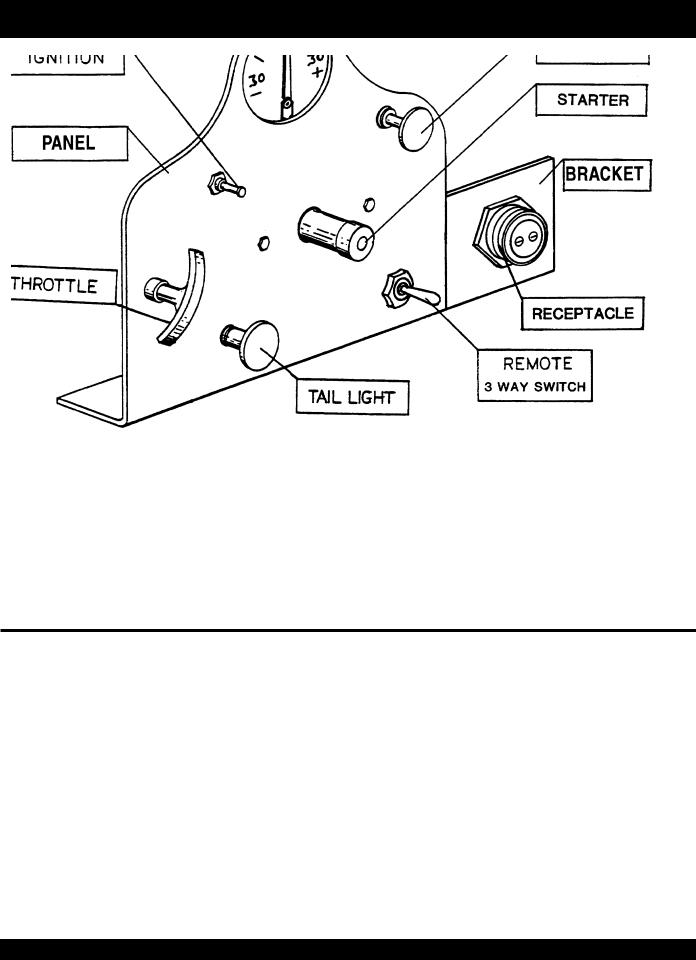
C-30HD — CONTROL PANEL
EM26733
EM26739
EM26735
EM26736
EM26753
EM14730
EM26789
EM26732
EM20708
EM40711
Before starting the engine, refer to the HATZ diesel or WISCONSIN air cooled engine manual for break-in instructions.
1.IGNITION-is a push/pull type control, to start the pump engine, the ignition control must be pulled out.
2.CHOKE-when starting the cold engine, close choke by pulling choke control to extreme out position. Once engine is running, push choke control all the way in.
3.STARTER-push in to start engine.
4.THROTTLE-is a variable speed type control. Turning the throttle to the left unlocks it allowing the control to be pulled out to the desired speed. Once the desired speed has been reached, turning the throttle control to the right locks it in place. Note-always unlock the throttle control before it is pushed in because if this is not done first, possible damage could result to the locking mechanism.
5.TAIL LIGHT-pull turns on tail light and push turns it off.
Before starting the concrete pumping procedure, let the engine warm up a minimum of five minutes. Also thoroughly read and understand the service manual for the C-30-HD concrete pump and become totally familiar with its operation before pumping.
PAGE 26 — C-30HD — PARTS & OPERATION MANUAL — REV. #4 (03/06/01)

NOTE PAGE
C-30HD — PARTS & OPERATION MANUAL — REV. #4 (03/06/01) — PAGE 27
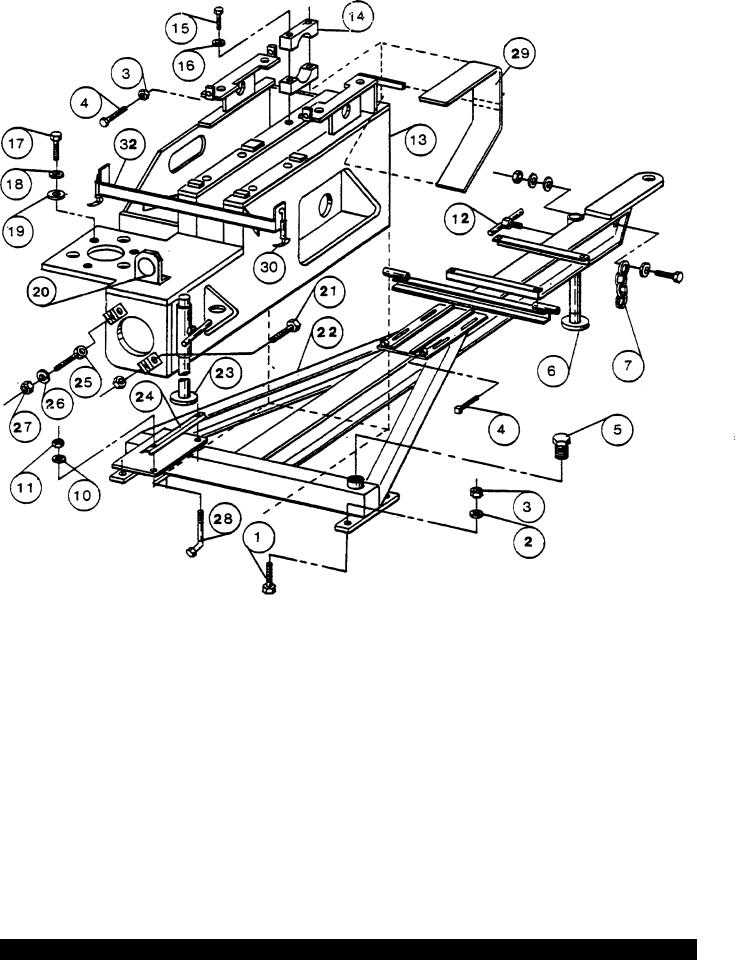
C-30HD — FRAME
PAGE 28 — C-30HD — PARTS & OPERATION MANUAL — REV. #4 (03/06/01)

C-30HD — FRAME
C-30HD CONCRETE PUMP
FRAME
NO. |
PART NO. |
PART NAME |
QTY. |
REMARKS |
1 |
EM117 |
BOLT, HEX 1/2-13X2 |
4 |
|
2 |
EM923346 |
WASHER, LOCK 1/2" ........................................ |
4 ........................ |
REPLACES EM606 |
3 |
EM406 |
NUT, HEX 1/2-13 |
4 |
|
4 |
EM130 |
BOLT, SQ. HEAD 1/2-13X2 1/2" |
5 |
|
5 |
EM20349 |
OILER PLUG |
1 |
|
6 |
EM14137 |
FRONT STAND ASSY (OLD STYLE) ............... |
1 ........................ |
PRIOR TO: 12-31-96 |
6 |
EM25610 |
SWIVEL JACK STAND ....................................... |
1 ........................ |
S/N 970101 & ABOVE |
6A |
EM508530 |
SUPPORT SWIVEL JACK ................................. |
1 ........................ |
S/N 970101 & ABOVE |
7 |
EM20135 |
SAFETY CHAIN |
1 |
|
12 |
EM14138 |
TEE HANDLE ASSY |
2 |
|
13 |
EM14100 |
PUMP BOX ASSY |
1 |
|
14 |
EM14116 |
JOURNAL BLOCK |
4 |
|
15 |
EM963180 |
BOLT, HEX 3/4-10X5 ......................................... |
4 ........................ |
REPLACES EM131 |
16 |
EM923350 |
WASHER, LOCK 3/4" |
4 |
|
17 |
EM104 |
BOLT, HEX 5/8-11X2 |
3 |
|
18 |
EM602 |
WASHER, LOCK 5/8 |
3 |
|
19 |
EM620 |
WASHER, WILLIAM 5/8 |
3 |
|
20 |
EM26536 |
TAIL LIGHT |
1 |
|
21 |
EM963614 |
BOLT, HEX 3/4-10X3 |
2 |
|
22 |
EM14142 |
FRAME ASSEMBLY |
1 |
|
23 |
EM14136 |
REAR STAND ASSY |
1 |
|
24 |
EM14711 |
BATTERY HOLD DOWN |
1 |
|
25 |
EM14165 |
WILLIAMS RE9B, 3/4X4 |
2 |
|
26 |
EM619 |
WASHER, WILLIAM 3/4" |
2 |
|
27 |
EM968446 |
NUT, HEX 3/4-10 |
4 |
|
28 |
EM145 |
BOLT, HEX 1/4-20X11 |
2 |
|
29 |
EM14119 |
CHAIN GUARD |
1 |
|
30 |
EM929028 |
HOOD LATCH .................................................... |
2 ........................ |
REPLACES EM20107-1 |
32 |
EM14120 |
HOOD REST ASSY |
1 |
|
|
EM26117 |
LUBE PLATE KIT ............................................... |
1 ........................ |
NOTE: THIS KIT IS USED TO |
|
|
|
|
ENCLOSE THE FRAME TO CREATE A |
SPLASH TYPE LUBRICATION SYSTEM. (CONTACT FACTORY FOR DETAILS)
C-30HD — PARTS & OPERATION MANUAL — REV. #4 (03/06/01) — PAGE 29
 Loading...