

i
Version 1.1
G52-MA00470
MS-6373(v1.X) ATX Mainboard
MSI
K7N420 Pro
ii
Manual Rev: 1.1
Release Date: Dec. 2001
FCC- B Radio Frequency Interference Statement
This equipment has been tested and found to comply with the limits for a class
B digital device, pursuant to part 15 of the FCC rules. These limits are designed
to pr ovide reasonable protection against harmful interference when the equipment is operated in a commercial environment. This equipment generates, uses
and can radiate radio frequency energy and, if not installed and used in accordance with the instruction manual, may cause harmful interference to radio
communications. Operation of this equipment in a residential area is likely to
cause harmful interference, in which case the user will be required to correct
the interference at his own expense.
Notice 1
The ch anges or mod ifications not expressly approved by the party responsible for compliance could void the user’s authority to operate the equipment.
Notice 2
Shielded interface cables and A.C. power cord, if any, must be used in order to
comply with the emission limits.
VOIR LA NOTICE D’INSTALLATION AVANT DE RACCORDER AU
R ESEAU.
Micro- Star International MS-6373
Tes ted to comply
with FCC Standard
For Home or Office Use

iii
Edit ion
Dec. 2001
Copyright Notice
The material in this document is the intellectual property of MICRO-STAR
INTERNA TIONAL. We take every care in the preparation of this document,
but no guarantee is given as to the correctness of its contents. Our products
are under co ntinual improvement and we reserve the right to make changes
without notice.
Trademarks
All trademarks are the properties of their respective owners.
Intel® and Pentium® are registered trademarks of Intel Corporation.
PS/2 and OS®/2 are registered trademarks of International Business Machines
Corpor ation.
W ind ows® 95/9 8/20 00/NT/XP are regi stered t rad emarks o f Mi crosoft
Corpor ation.
Netware® is a registered trademark of Novell, Inc.
A ward® is a registered trademark of Phoenix Technologies Ltd.
AMI® is a registered trademark of American Megatrends Inc.
Revision His tory
Revision Revision His tory Date
V 1.1 Release for channel Dec. 2001
product

iv
1. Read the safety instructions carefully.
2. Save this User’s Guide for possible use later.
3. Keep this equipment away from humidity.
4. Lay this equipment on a stable and flat surface before setting it up.
5. The openings on the enclosure are used for air convection and to prevent
the equipment from overheating. Note: Do not cover the openings.
6. Make sure that the power voltage is within its safety range and has been
adjusted properly to the value of 110/220V before connecting the equipment to the power inlet.
7. Place the power cord in a way that people are unlikely to step on it. Do not
place anything on the power cord.
8. Alw ays unplug the power cord before inserting any add-on card or module.
9. All cautions and warnings on the equipment should be noted.
10. Never pour any liquid into the opening that could damage the equipment
or cause an electrical shock.
11. If any of the following situations arises, get the equipment checked by a
service personnel:
l the power cord or plug is damaged
l liquid has penetrated into the equipment
l the equipment has been exposed to moisture
l the equipment has not work well or you can not get it work according
to User’s Guide
l the equipment was dropped and damaged
l the equipment has obvious signs of breakage
12. Do not leave the equipment in an unconditioned environment with a storag e temp erature of 6 00 C (1400F) or a bove, which may damage the
equipment.
Safety Instructions
CAUTION: To p reve nt explo sion caused by impro per batt ery
replacement, use the same or equivalent type of battery recommended
by the manufacturer only.

v
CONTENTS
Chapter 1 Getting Started................................................................................. 1-1
Specification ................................................................................................... 1-2
Mainboar d Layout ........................................................................................ 1-5
MSI Special Features.................................................................................... 1-6
PC Alert
TM
III ..........................................................................................1-6
D-BracketTM(optional)........................................................................... 1-8
Live BIOSTM/Live Driver
TM
.................................................................................................. 1-10
Chapter 2 Hardware Setup ................................................................................ 2-1
Central Processing Unit: CPU......................................................................2-2
CPU Installation Procedure.................................................................. 2-2
CPU Core Speed Derivation Procedure .............................................. 2-3
Mem ory ........................................................................................................... 2-4
Introduction to DDR ............................................................................. 2-4
DDR Module Combination................................................................... 2-5
DDR Module Installation Procedure .................................................. 2-5
Power Supply................................................................................................. 2-6
A TX 20-Pin Power Connector .............................................................. 2-6
Back Panel ......................................................................................................2-7
Mouse Connector.................................................................................. 2-7
Keyboard Connector.............................................................................2-8
USB Connectors .................................................................................... 2-8
Serial Port Connectors: COM A/COM 2 ............................................ 2-9
VGA Connector...................................................................................... 2-9
LAN Jack (optional) ............................................................................ 2-10
Game Port & Audio Ports................................................................... 2-10
Parallel Port ...........................................................................................2-11
Connectors ...................................................................................................2-12
Floppy Disk Drive Connector: FDD1 ................................................ 2-12
USB Front Connector: USB3 & USB 4 ............................................. 2-12

vi
Hard Disk Connectors: IDE1&IDE2 .................................................. 2-13
CD1/AUX1/MOD EM1/JSP1 .............................................................. 2-14
CPUF AN1/PSFAN1/SYSFAN1 .......................................................... 2-15
IrDA Infrared Module Header: IR or IR1 ......................................... 2-16
Case/Speaker Connectors: JFP2/MSIFP.......................................... 2-17
D-BracketTM Connector: JDLED (optinal)........................................ 2-18
Front Panel Audio Connector: JAUDIO2 ........................................ 2-19
Jumpers......................................................................................................... 2-20
Clear CMOS Jumper: JBAT1 .............................................................. 2-20
FSB Mode Jumper: SW2 .................................................................... 2-21
Audio Contorl Jumper: JA1 ............................................................... 2-22
Keyboard Wake-up Jumper: JKBV1 ................................................. 2-23
Slots ..............................................................................................................2-24
AGP Slot .............................................................................................. 2-24
PCI Slots ............................................................................................... 2-25
CNR Slot ...............................................................................................2-25
Chapter 3 AWARD BIOS Setup....................................................................... 3-1
Entering Setup............................................................................................... 3-2
Control Keys.......................................................................................... 3-2
Getting Help ...................................................................................................3-3
Main Menu ............................................................................................. 3-3
Sub-Menu............................................................................................... 3-3
General Help <F1>................................................................................. 3-3
Default Settings..................................................................................... 3-3
Setup Menus ................................................................................................. 3-4
Main Menu ............................................................................................. 3-4
Standard CMOS Features ....................................................................3-6
Advanced BIOS Features .................................................................... 3-9
Advanced Chip set Features .............................................................. 3-13
Integrated Peripherals.........................................................................3-15

vii
Power Management Setup ................................................................. 3-20
PnP/PCI Configurations...................................................................... 3-24
PC Health Status.................................................................................. 3-26
Frequency/Voltage Control ................................................................3-28
Load High Performance/BIOS Setup Defaults ................................ 3-29
Set Supervisor/User Password ..........................................................3-30
App endix: DDR DIMM Configuration.............................................................A-1
Glossary................................................................................................................G -1

Getting Started
1-1
Chapter 1. Getting Started
1
Getting Started
Congratulations on purchasing the MSI mainboard. K7N420 Pro
(MS-6373) A TX mainboard is an excellent computer mainboard based on
the innovative nForce 420D chipset, which supports the latest AMD
®
Athlon/Athlon XP/Duron processor series and provides you with a costeffective solution.
TOPICS
Mainboard Specification 1-2
Mainboard Layout 1-5
MSI Special Features 1-6

Chapter 1
1-2
Mainboard Specification
C PU
Supports Socket A (Socket 462) for AMD Athlon/Athlon XP/Duron
processors up to 1800+MHz
Chipset
nForce 420D chipset
- Support 200/266MHz FSB
- Twinbank Memory Architecture/128-bit DDR memory controller
- Integrated GeForceMX-class advanced Graphics Processing Unit
- AGP 4x support
- Hyper Transport interface to MCP (800MB/sec max.)
MCP-D(Media Communications Processor)
- Dual ATA/100 controller
- Support USB UHCI 1.0a, provide up to six USB ports
- IEEE 802.3 compatible MAC (MII)
- Integrated Audio Processor Unit, AC’97 2.1 compliant
- SPDIF output function
Main Memory
Support up to three DDR DIMMs
- Maximum memory size up to 1.5GB
- Support 128-bit system memory
Slo ts
One AGP slot
- Support AGP 2.0 2x/4x (1.5V only)
One CNR slot
Five PCI slots
- 32-bit Master PCI 2.2 compliant
- Support 3.3v/5v PCI bus interface
On -board IDE
An IDE controller on the MCP chipset provides IDE HDD/CD-ROM
with PIO, Bus Master and Ultra DMA 100 operation modes
Support up to four IDE devices connection

Getting Started
1-3
V ideo
256- bit 2D/3D graphics accelerator
Supports the 2nd generation T&L engine, nVIDIA Shading Rasterizer
Supports TV-out daughter card (optional)
A udio
APU (audio processing unit) integrated in MCP
- Support up to 256 hardware-processed voices or 64 hardware voice in
3D
- S/PDIF out through external bracket
- CNR card for 6 channel analog (optional)
Net work (optional)
Chipset integrated10/100 Base-T Ethernet/Fast Ethernet
On-b oard Peripherals
One floppy port that supports two FDD with 360KB, 720KB, 1.44MB
and 2.88MB
Two serial ports COM A+COM 2 (pin header)
One parallel port that supports SPP/EPP/ECP modes
One VGA connector
Six USB ports (2 x rear connectors and 2 x USB front pin header to
suppo rt four ports)
One IrDA connector
One RJ-45 connector for Ethernet (optional)
One Audio/Game port
One D-Bracket pin header
BIOS
The mainboard BIOS provides “Plug & Play” BIOS that can detect
the periph-eral devices and expansion cards installed on the board
automatically
Support Desktop Management Interface (DMI) function that can record
your mainboard specifications

Chapter 1
1-4
Dimension
30.5cm x 22.5cm
Mounting
Six m ounting holes
Getting Started
1-5
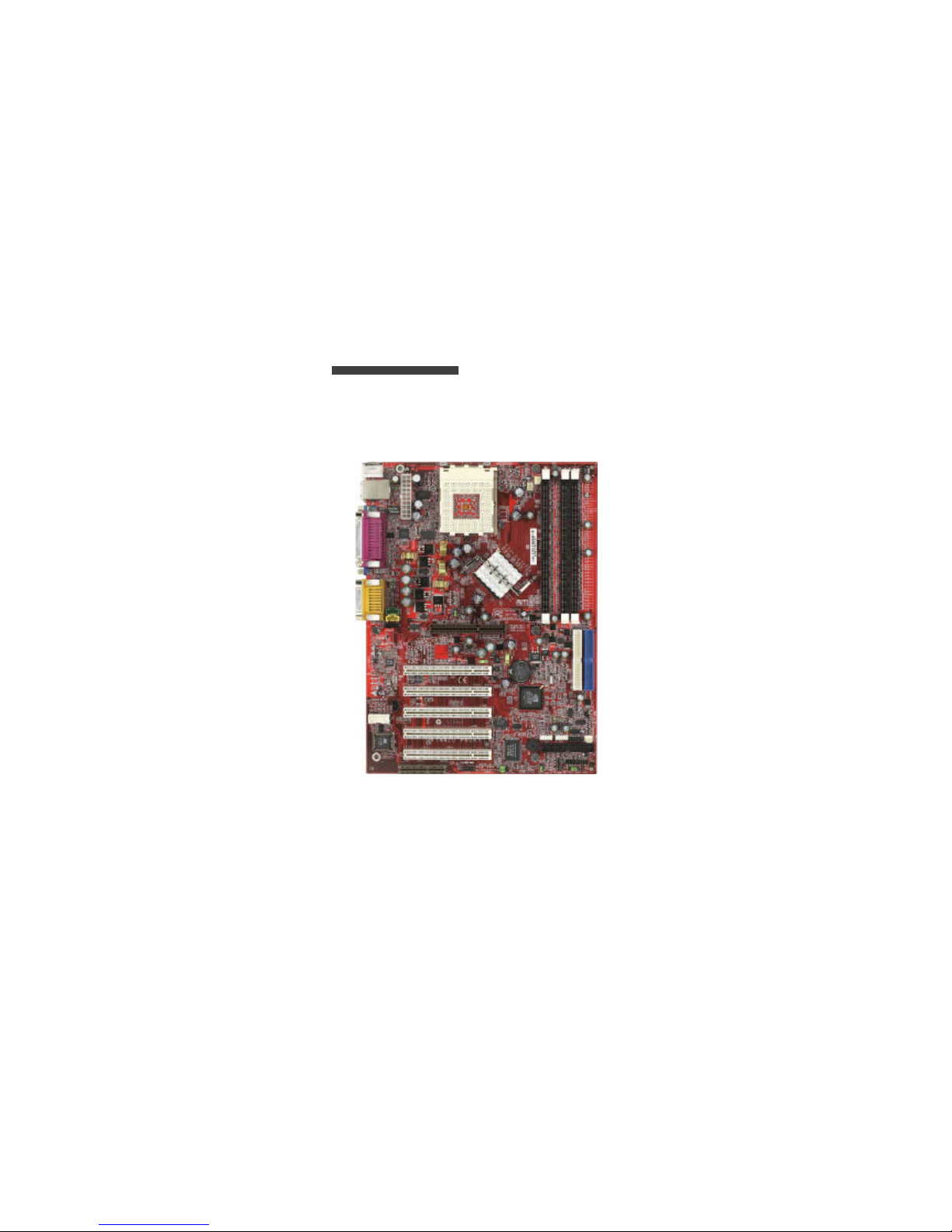
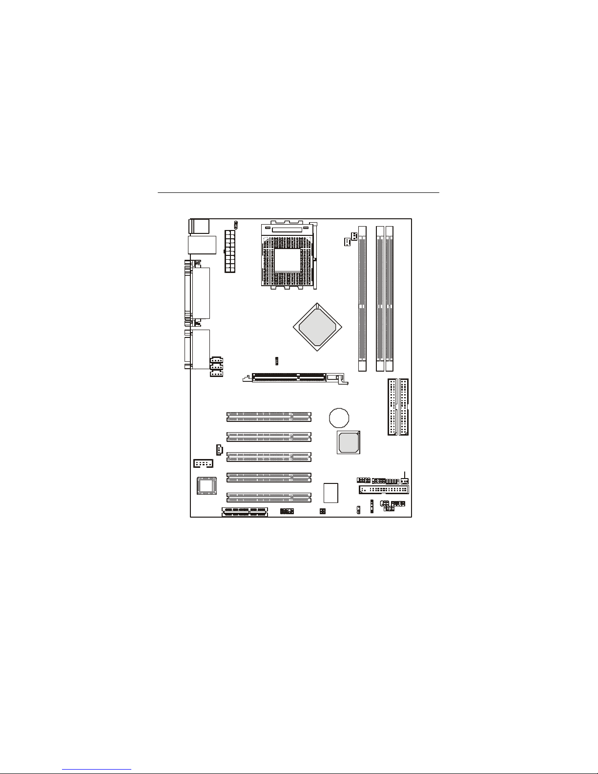
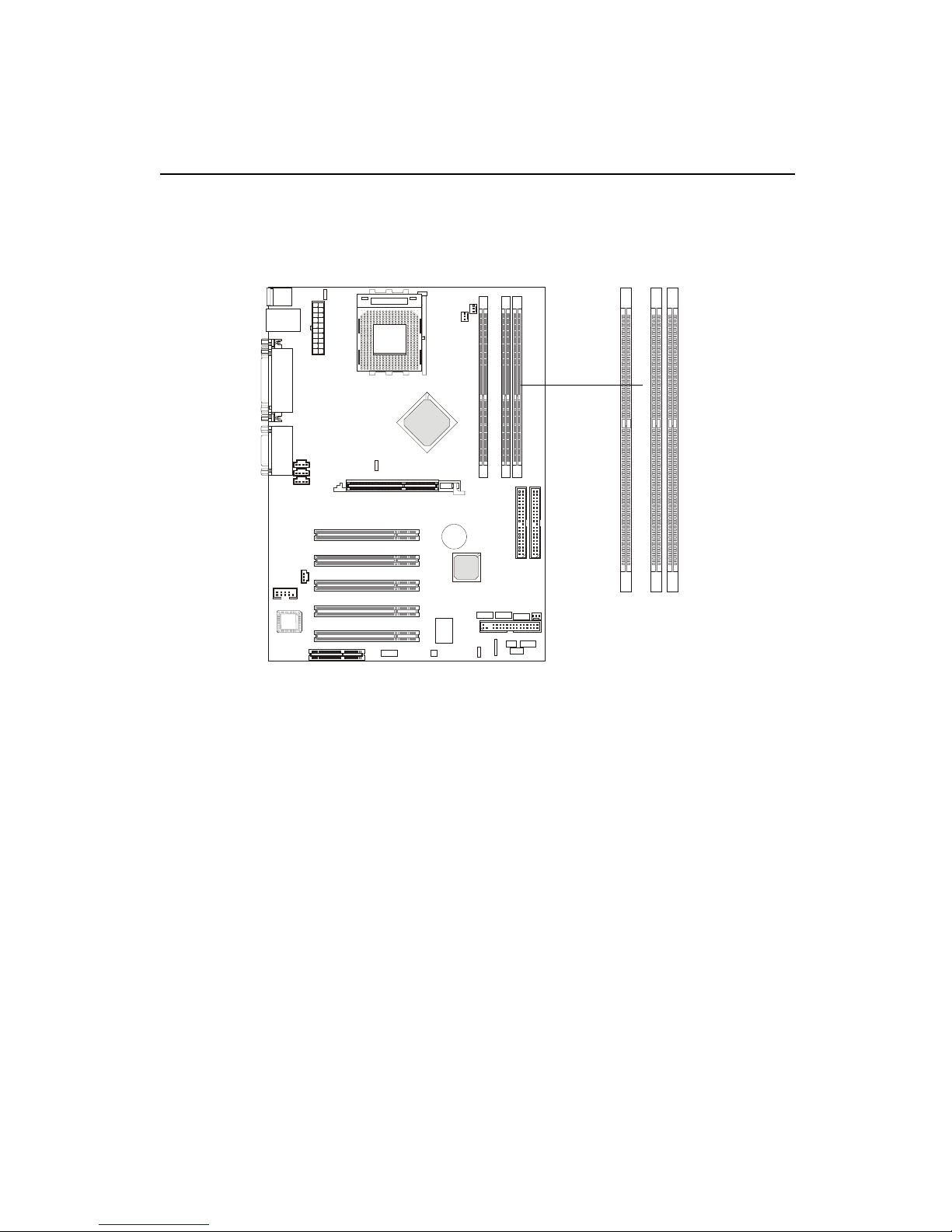
Mainboard Layout
K7N420 Pro (MS-6373 v1.X) ATX Mainboard
AGP Slot
BATT
+
nVIDIA
MCP-D
nVIDIA
CRUSH 12
D
D
R
1
D
D
R
2
D
D
R
3
USB3
JFP2
USB4
JDLED
JA1
JAUDIO2
ATX
Power Supply
SYSFAN1
JBAT1
W
i
n
b
o
n
d
W
8
3
6
2
7
F
H
-
A
W
IR
MSIFP
SW2
JSP1
SOCKET 462
BIOS
PCI Slot 5
PCI Slot 4
PCI Slot 3
PCI Slot 2
PCI Slot 1
IDE2 IDE1
CNR
Top : Parallel Port
Bottom:
COM A
VGA Port
JKBV1
PSFAN1
CPUFAN1
Top : mouse
Bottom: keyboard
Top: LAN Jack
Bottom: USB
ports
CD1
MODEM1
AUX1
Top :
Game port
Bottom:
Line-Out
Line-In
Mic
COM 2
FDD 1
IR1
Chapter 1
1-6
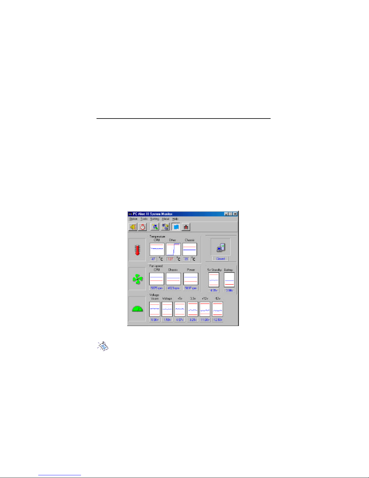
PC Alert™ III
The PC AlertTM III is a utility you c an find in the CD-ROM disk . The
utility is just like your PC doctor that can detect the following PC hardware
status during real time operation:
* monitor CPU & system temperatures
* monitor fan speed(s)
* monitor system voltage
* monitor chassis intrusion
If one of the items above is abnormal, the program main screen will be
immediately shown on the screen, with the abnormal item highlighted in red.
This will continue to be shown,until user disables the warning.
Note: It ems shown on PC Alert III vary dependin g on your system’s
status.
MSI Special Features

Getting Started
1-7
Feat ures:
l Network Management
- Monitoring & remote control
l Basic System Utilities
- Scandisk & Defragment to maintain your HDD
l 3D Graphics Design
- Enables a more friendly user interface
l Sofware Utilities
- SoftCooler Optimized Cooling
Chapter 1
1-8
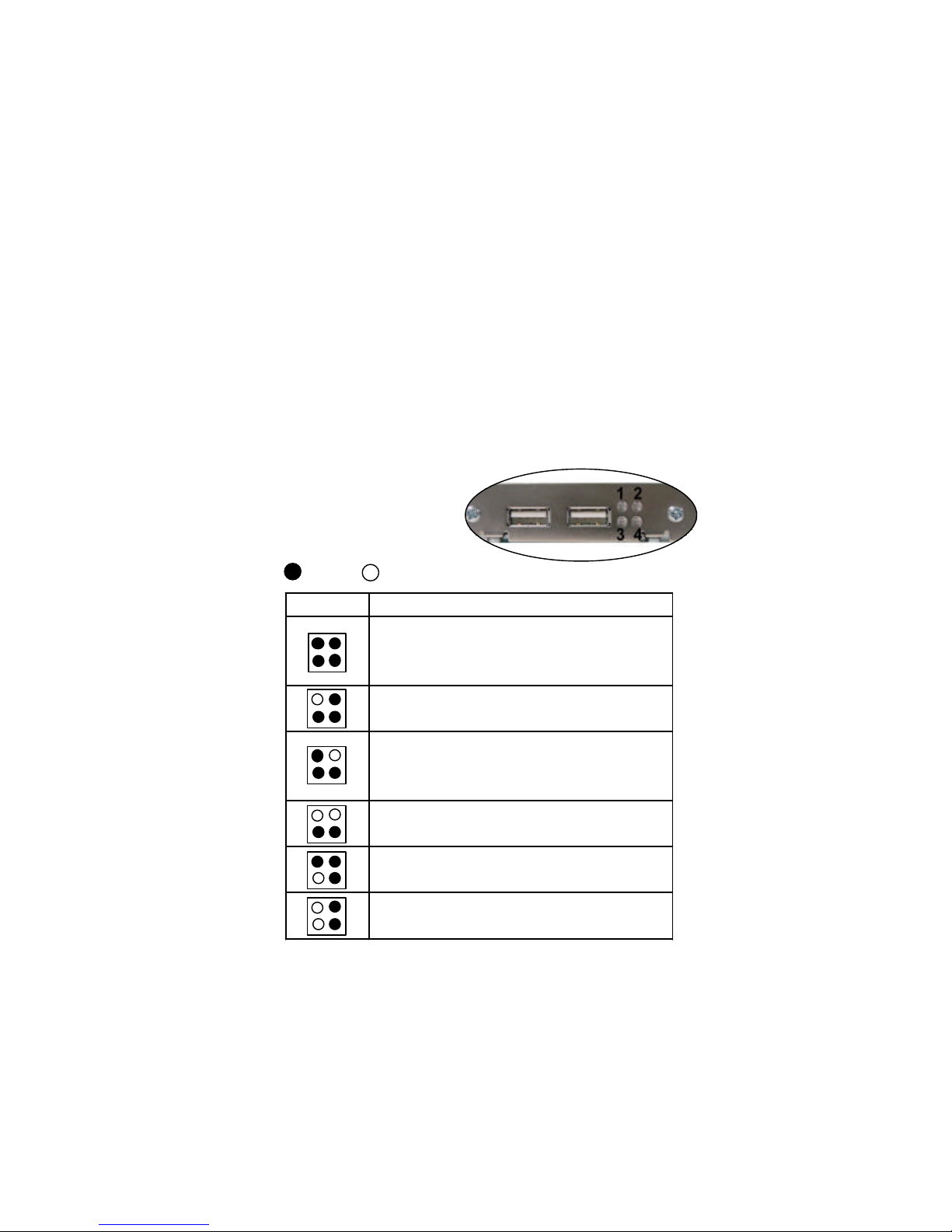
D-B racket™
(optional)
-Bracket™ is an USB bracket integrating four Diagnostic LEDs, which
use graphic signal display to help users understand their system. The LEDs
provide up to 16 combinations of signals to debug the system. The 4 LEDs can
debug all problems that fail the system, such as VGA, RAM or other failures.
This special feature is very useful for the overclocking users. These users can
use the feature to detect if there are any problems or failures.
D -Bracket™
D -Bracket Description
System Power ON
- The D-LED will hang here if the processor is damaged or
not installed properly.
Early Chipset Initialization
Memory Detection Test
- Testing onboard memory size. The D-LED will hang if
the memory module is damaged or not installed properly.
Decompressing BIOS image to RAM for fast booting.
Initializing Keyboard Controller.
Testing VGA BIOS
- This will start writing VGA sign-on message to the screen.
1 2
3 4
Red
Green
Getting Started
1-9
D-Bracket Description
Processor Initialization
- This will show information regarding the processor (like
brand name, system bus, etc…)
Testing RTC (Real Time Clock)
Initializing Video Interface
- This will start detecting CPU clock,
checking type of video
onboard. Then, detect and initialize the video adapter.
BIOS Sign On
- This will start showing information about logo, processor
brand name, etc….
Testing Base and Extended Memory
- Testing base memory from 240K to 640K and extended
memory above 1MB using various patterns.
Assign Resources to all ISA.
Initializing Hard Drive Controller
- This will initialize IDE drive and controller.
Initializing Floppy Drive Controller
- This will initializing Floppy Drive and controller.
Boot Attempt
- This will set low stack and boot via INT 19h.
Operating System Booting
1 2
3 4
Chapter 1
1-10
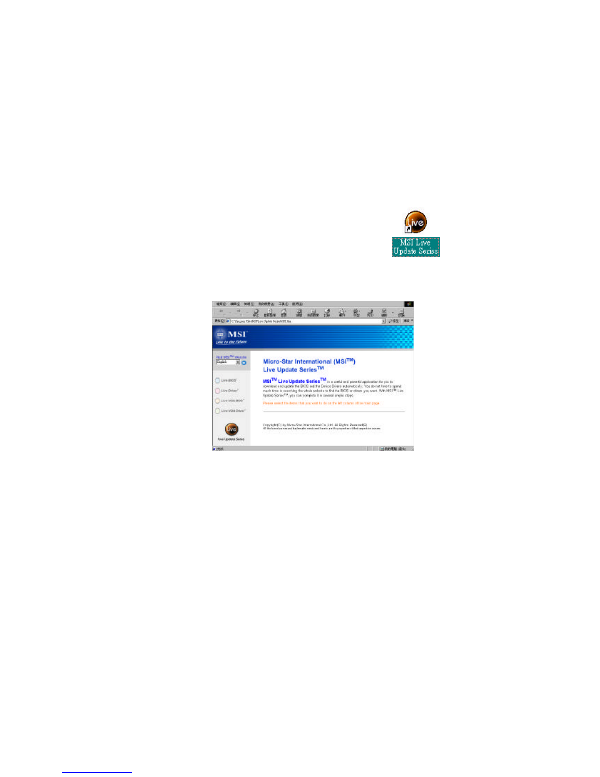
L ive BIOS™/Live D river™
The Live BIOSTM is a tool used to detect and update your
BIOS online so that yo u don’t need to search for the co rrect
BIOS version through the whole web site. To use the function,
you need to install the “MSI Live Update Series” application.
After installation, the “MSI Live Update Series” icon (a s the
right view ) will appear on the screen.
Double click the “MSI Live Update Series” icon, and the following screen
will appear.
Four but tons are placed on the left column of the screen. Click the desired
button to start the update process.
l
Live BIOS – Updates the BIOS online. If your motherboard does not support
the function, the “sorry” message is displayed.
l
Live D river – U pdates the drivers online. If your motherboard does not sup-
port the function, the “sorry” message is displayed.
l
Live VGA BIOS – Updates the VGA BIOS online. If your VGA device does
not s upport the function, the “sorry” message appears.
l
Live VGA Driver – Updates the VGA driver online. If your VGA device does
not s upport the function, the “sorry” message is displayed.
For more information on the update instructions, insert the companion CD and
refer to the “Live Update Series Guide” under the “Manual” tab.

Hardware Setup
2-1
This chapter provides you with the information about hardware setup
procedures. While doing the installation, be careful in holding the components
and follow the installation procedures. For some components, if you install in
the wrong orientation, the components will not work properly.
Use a grounded wrist strap before handling computer components. Static
electricity may damage the components.
TOPICS
Central Processing Unit: CPU 2-2
Memory 2-4
Power Supply 2-6
Back Panel 2-7
Connectors 2-12
Jumpers 2-20
Slots 2-24
Chapter 2. Hardware Setup
2
Hardware Setup
Chapter 2
2-2
Central Processing Unit: CPU
The mainboard provides a Socket A (Socket 462) to support the latest
AMD Athlon/Athlon XP processor series. To avoid the thermal issue* of
the CPU, please make sure that the CPU has a heatsink and a cooling fan
attached on its top.
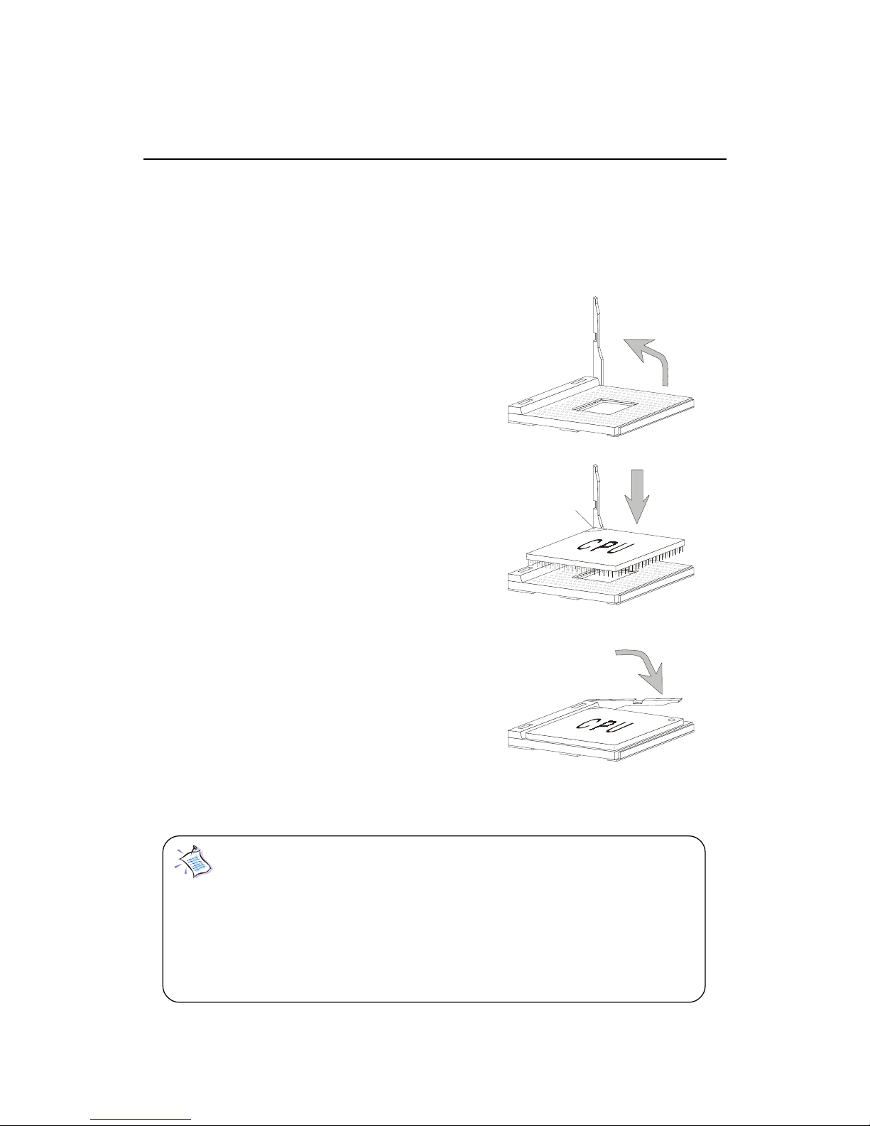
CPU Installation Procedure
To install the CPU, please follow the steps below:
1. Pull the lever sideways away
from the socket; then, raise it
up to a 90-degree angle.
2. Locate the cut edge on the CPU,
and point it towards the lever
pivot. Insert the pins of the CPU
directly into the holes on the socket.
3. Press the lever down to complete
the installation.
Note: The CPU is designed with the corner pin on the
two of the four corners; thus, it should only fit in one correctly
orientation as installing. In addition, with the weight of the
heatsink and cooling fan attached, you can insert the CPU into
the socket easily. DO NOT press the CPU down by force when
installing in wrong orientation, this would bend and damage
Open Lever
Cut edge
Sliding
Plate
Close
Lever

Hardware Setup
2-3
CPU Core Speed Derivation Procedure
If CPU Clock = 100MHz
Core/Bus ratio = 14
then CPU core speed = Host Clock x Core/Bus ratio
= 100MHz x 14
= 1.4GHz
* Thermal issue for CPU
As processor technology pushes to faster speeds and higher performance,
thermal management becomes increasingly crucial when building computer
system. Maintaining the proper thermal environment is key to reliable
operation. As such, the processor must be maintained in the specified
thermal requirements. AMD recommends the use of high performance
thermal interface material.
AMD Athlon/Athlon XP processors with a speed of 600MHz and above
require the LARGER heatsink and cooling fan. You also need to add thermal
grease between the CPU and heatsink to improve heat dissipation; then,
make sure that the CPU and the heatsink are securely fastened and in good
contact with each other. These are needed to prevent damaging the processor and ensuring reliable operation.
For more information on the issue and proper cooling solution, please visit
AMD website at: http:// www.amd.com/products/cpg/athlon/pdf/
cooling_guide.pdf
Chapter 2
2-4
Memory
Introduction to DDR SDRAM
DDR (Double Data Rate) SDRAM is similar to conventional SDRAM,
but doubles the rate by transferring data twice per cycle. It uses 2.5 volts as
opposed to 3.3 volts used in SDR SDRAM, and requires 184-pin DIMM modules rather than 168-pin DIMM modules used by SDR SDRAM. Two types of
DDR are available at the time of writing: PC1600 & PC2100. PC1600 DDR SDRAM
running at 100MHz will produce about 1.6GB/s memory bandwidth. PC2100
running at 133MHz will produce 2.1GB/s memory bandwidth. High memory
bandwidth makes DDR an ideal solution for high performance PC, workstations and servers.
DDR DIMM Slots
(DDR 1~3)
D
D
R
1
D
D
R
2
D
D
R
3
The mainboard provides three 184-pin DDR DIMM slots and sup-
ports a total memory size up to 1.5 GB.
Hardware Setup
2-5
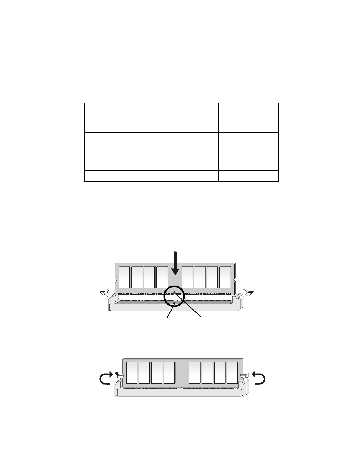
DDR Module Combination
You can install PC1600/PC2100 DDR SDRAM modules into the DDR
DIMM slots (DDR 1~3) in any combination as follows:
DDR Module Installation Procedure
1. The DDR DIMM has only one notch on the center of module.
The module will only fit in the right orientation.
2. Insert the DIMM memory module vertically into the DIMM
slot. Then push it in.
3. The plastic clip at each side of the DIMM slot will automatically
close.
Socket Memory Module Total Memory
DIMM 1 64MB, 128MB,
64MB ~ 512MB
256MB, 512MB
DIMM 2 64MB, 128MB,
64MB ~ 512MB
256MB, 512MB
DIMM 3 64MB, 128MB,
64MB ~ 512MB
256MB, 512MB
Maximum System Memory Supported 64MB ~ 1.5GB
Volt
notch
Chapter 2
2-6
Power Supply
ATX 20-Pin Power Connector
This connector allows you to connect to an ATX power supply. To
connect to the ATX power supply, make sure the plugs of the power supply is
inserted in the proper orientation and the pins are aligned. Then push down
the power supply firmly into the connector. The power connector supports
instant power on function which means that system will boot up immediately
when the power supply connector is inserted on the board.
The mainboard supports ATX power supply for the power system. Before inserting the power supply connector, always make sure that all components are installed properly to ensure that no damage will be caused.
PIN SIGNAL
11 3.3V
12 -12V
13 GND
14 PS_ON
15 GND
16 GND
17 GND
18 -5V
19 5V
20 5V
PIN SIGNAL
1 3.3V
2 3.3V
3 GND
45V
5 GND
65V
7 GND
8 PW_OK
9 5V_SB
10 12V
Pin Definition
10
1
20
11
Hardware Setup
2-7
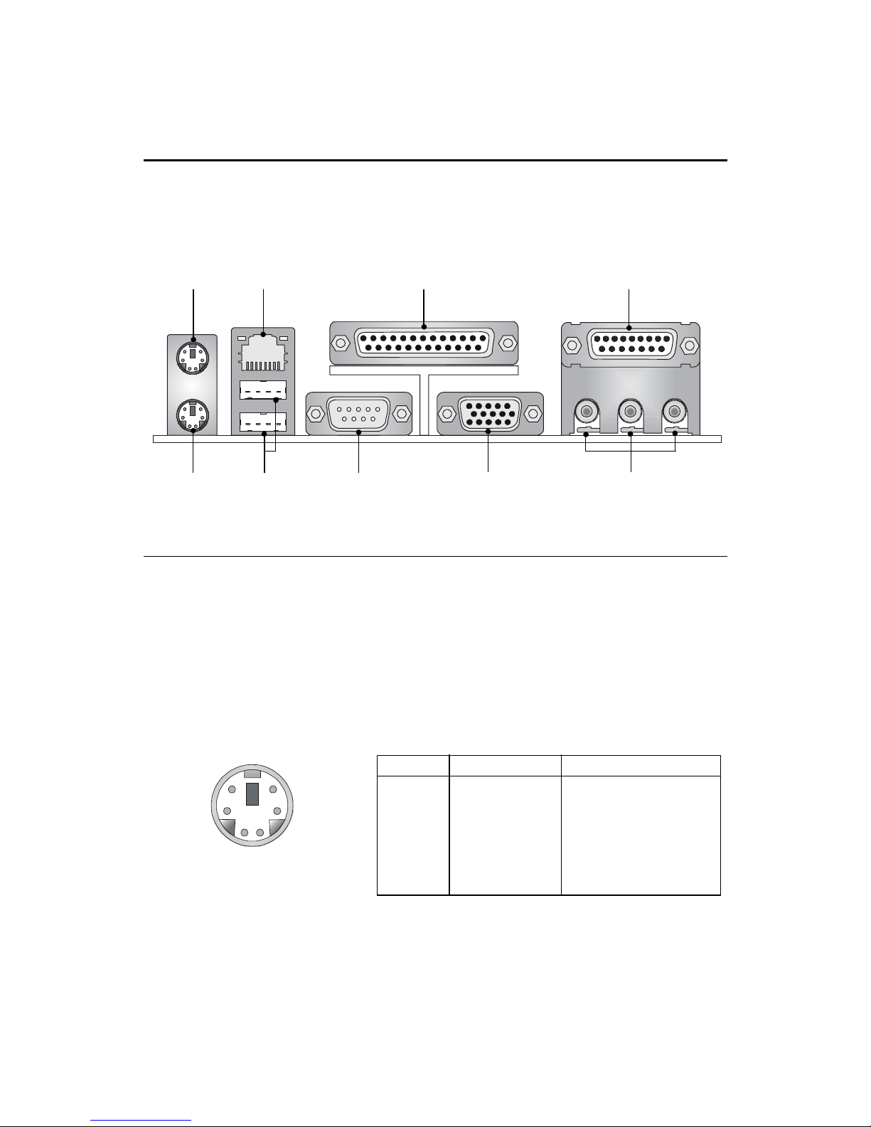
The Back Panel provides the following connectors:
Back Panel
Mouse Connector
The mainboard provides a standard PS/2® mouse mini DIN connector for
attaching a PS/2® mouse. You can plug a PS/2® mouse directly into this
connector. The connector location and pin assignments are as follows:
PS/2 Mouse (6-pin Female)
PIN SIGNAL DESCRIPTION
1 Mouse DATA Mouse DATA
2 NC No connection
3 GND Ground
4 VCC +5V
5 Mouse Clock Mouse clock
6 NC No connection
Pin Definition
Mouse
Keyboard
LAN Jack
USB Ports
Parallel Port
Serial Port VGA Connector
Game Port
Audio Ports
2
1
3
4
56
 Loading...