

Motorola MC100LVE164FAR2, MC100LVE164, MC100LVE164FA Datasheet
SEMICONDUCTOR TECHNICAL DATA
4–1
REV 1
Motorola, Inc. 1996
6/95
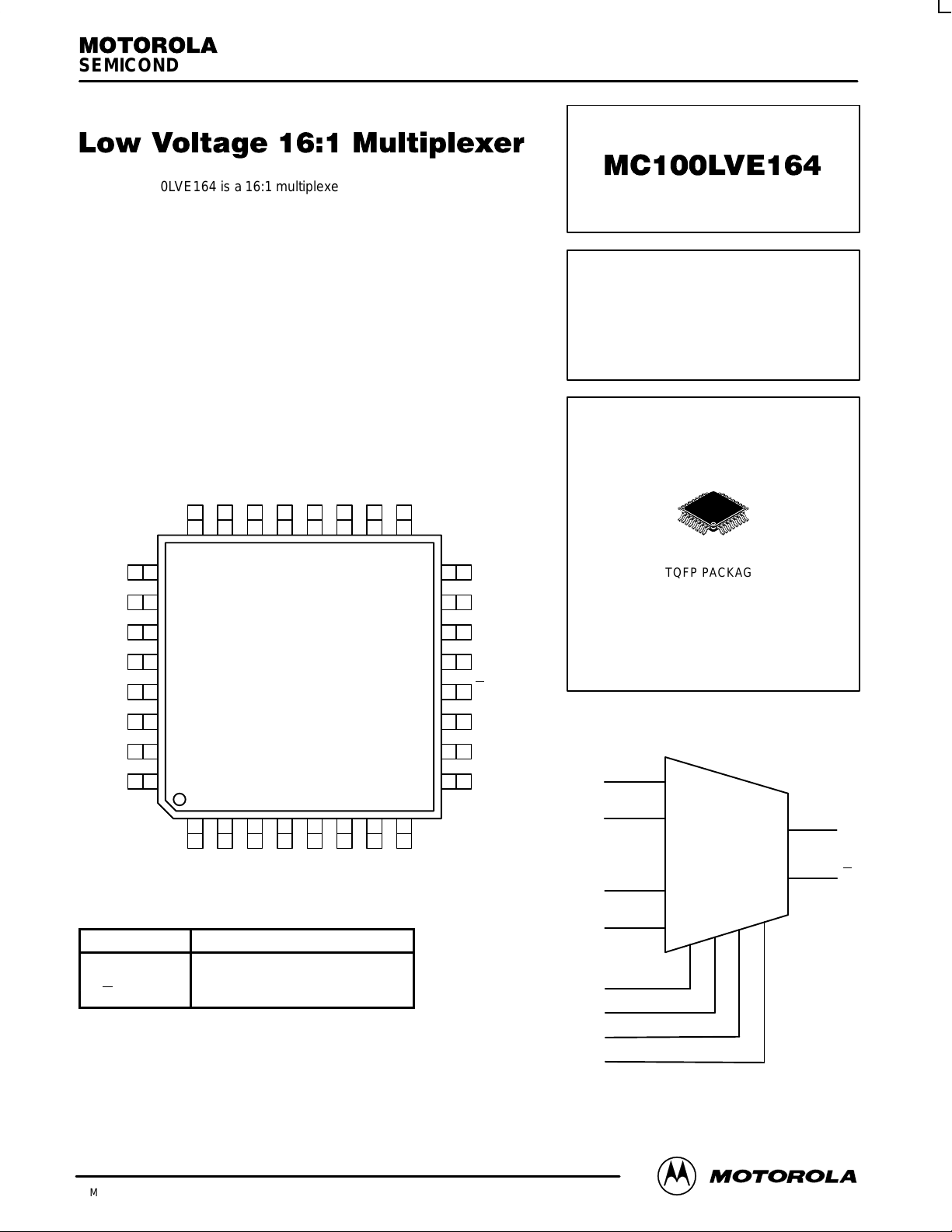
The MC100LVE164 is a 16:1 multiplexer with a differential output. The
select inputs (SEL0, 1, 2, 3 ) control which one of the sixteen data inputs
(A0 – A15) is propagated to the output. The device is functionally
equivalent to the MC100E164 except it operates from a –3.3V supply.
The device is packaged in the 32–lead TQFP. The TQFP has a 7x7mm
body with a 0.8mm lead pitch.
Special attention to the design layout results in a typical skew between
the 16 inputs of only 50ps.
• 850ps Data Input to Output
• Differential Output
• Extended 100E V
EE
Range of –3.0V to –3.8V
• Internal 75kΩ Input Pulldown Resistors
Q
Pinout: 32-Lead TQFP (Top View)
NC
A10
A9
A8
A7
A6
A5
NC
NC
SEL3
VCC
Q
SEL2
SEL1
SEL0
NC
A11
A12
A13
A14
A15
VCC
NC
NC
A4
A3
A2
A1
A0
VEE
NC
25
26
27
28
29
30
31
32
15
14
13
12
11
10
9
1 2 3 4 5 6 7 8
24 23 22 21 20 19 18 17
16
MC100LVE164
PIN NAMES
Pin Function
A0– A
15
Data Inputs
SEL[0:3] Select Inputs
Q, Q Output
LOW VOLTAGE
16:1 MULTIPLEXER
FA SUFFIX
TQFP PACKAGE
CASE 873A–02
LOGIC DIAGRAM
A
0
A
1
A
14
A
15
SEL0
SEL1
SEL2
SEL3
Q
Q
16:1
MC100LVE164
MOTOROLA ECLinPS and ECLinPS Lite
DL140 — Rev 3
4–2
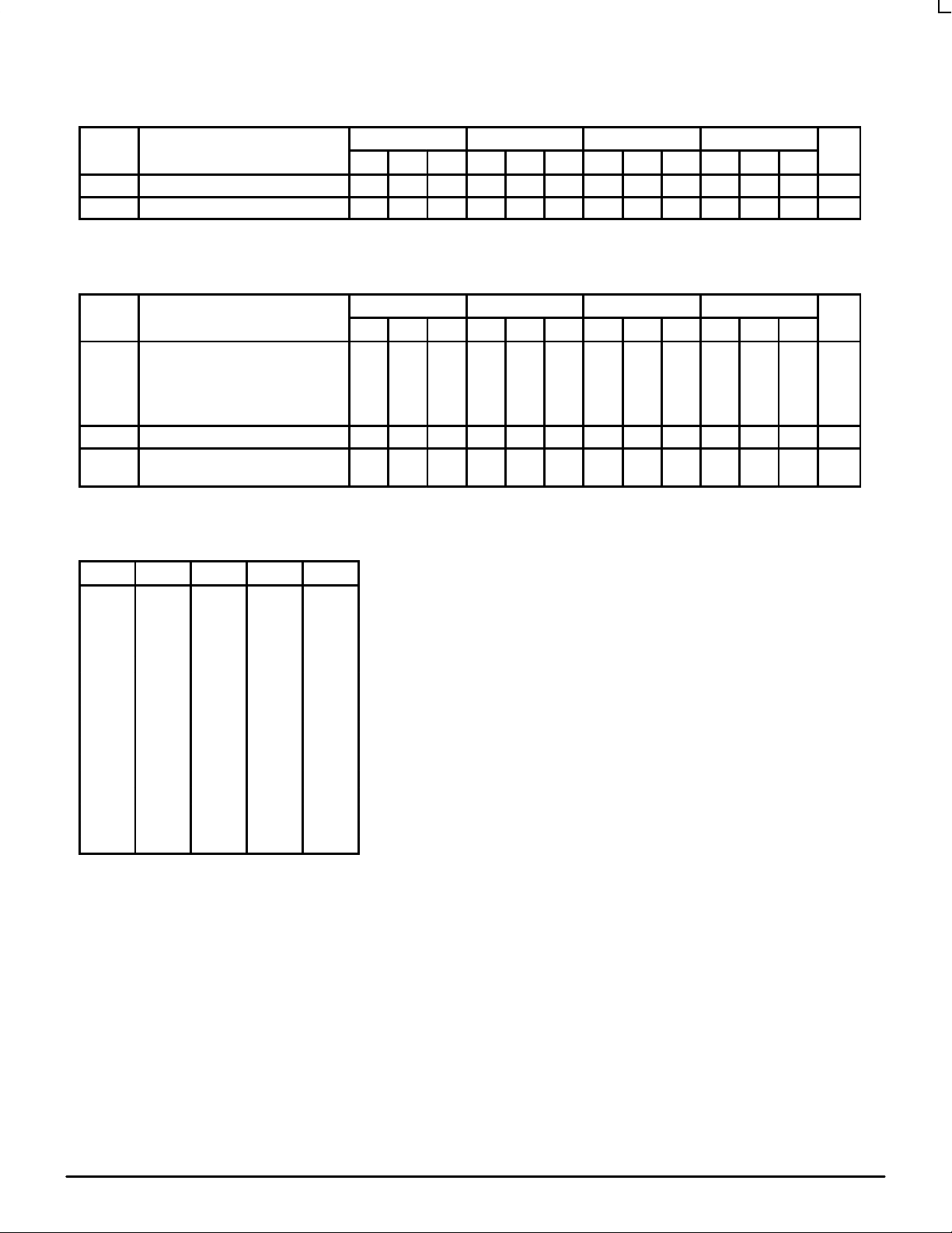
DC CHARACTERISTICS (VEE = VEE(min) to VEE(max); VCC = V
CCO
= GND)
–40°C 0°C 25°C 85°C
Symbol Characteristic Min Typ Max Min Typ Max Min Typ Max Min Typ Max Unit
I
IH
Input HIGH Current 150 150 150 150 µA
I
EE
Power Supply Current 34 45 34 45 35 45 37 45 mA
AC CHARACTERISTICS (VEE = VEE(min) to VEE(max); VCC = V
CCO
= GND)
–40°C 0°C 25°C 85°C
Symbol Characteristic Min Typ Max Min Typ Max Min Typ Max Min Typ Max Unit
t
PLH
t
PHL
Propagation Delay A Input
to Output SEL0
SEL1
SEL2
SEL3
350
500
400
400
400
600
700
675
675
550
850
900
900
900
700
350
500
400
400
400
600
700
675
675
550
850
900
900
900
700
350
500
400
400
400
600
700
675
675
550
850
900
900
900
700
350
500
400
400
400
600
700
675
675
550
850
900
900
900
700
ps
t
SKEW
Within Device Skew
1
75 75 50 50 ps
t
r
t
f
Rise/Fall Times 20% – 80% 275 400 550 275 400 550 275 400 550 275 400 550 ps
1. Within Device skew is defined as the difference in the A to Q delay between the 16 different A inputs.
FUNCTION TABLE
SEL3 SEL2 SEL1 SEL0 Data
L L L L A0
L L L H A1
L L H L A2
L L H H A3
L H L L A4
L H L H A5
L H H L A6
L H H H A7
H L L L A8
H L L H A9
H L H L A10
H L H H A11
H H L L A12
H H L H A13
H H H L A14
H H H H A15
 Loading...