How it Works
Log In / Sign Up
Buy Points
How it Works
FAQ
Contact Us
Questions and Suggestions
Users
Motorola
Loading...
G
GM3689
GM380
GM950
Gold FLX
2
GoldLine
GP 2000
2
GP2000s
GP300
2
GP308
GP3188
GP320
gp328
2
GP329 PLUS
GP330
GP338
2
GP338 Plus
GP338 XLS
GP339 PLUS
GP340
3
GP340 ATEX
GP340 EX
GP344
2
GP350
2
GP366R
GP3688
2
GP380
GP640
2
GP644
GP68
2
GR300+GR500
Grasp
2
GSM L2
2
GT10
GTX
GV-701
GV-800
H
H01UCC6DU3AN
H11AA1
H11AA3
H11AA4
H11AAV1
H11AAV2
H11B1
H11B3
H11D1
H11D2
H11G1
H11G2
H11G3
H11L1
H11L2
H12
H15
H17
H270
5
H3
3
H300
3
H350
3
H375
4
H385
H390
4
H500
6
H505
2
H525
H550
2
H555
H560
4
H605
3
H620
4
H62XAH6RR1AN
H65XAN6RR4BN
H670
3
H680
8
H700
8
H710
3
H715
2
H720
H721
H730
H76XAH6JR7BN
2
H76XAN9JR9AN
H780
2
H790
H7 Razrwire
H800
3
H9
3
H9 MINIBLUE
Hasselblad True Zoom
3
HC05J5AGRH
HC05J5AGRS
HC12
HDDSR 605
HDPVR 630
HDST-25MM-PTVP-01
3
HDT100
3
HDT101
5
HE-8000
HE-8000 I
HF800
HF-SSB
Loading...
Loading...
Nothing found
H11L2
Datasheet
6 pgs
281.98 Kb
0
Table of contents
Loading...
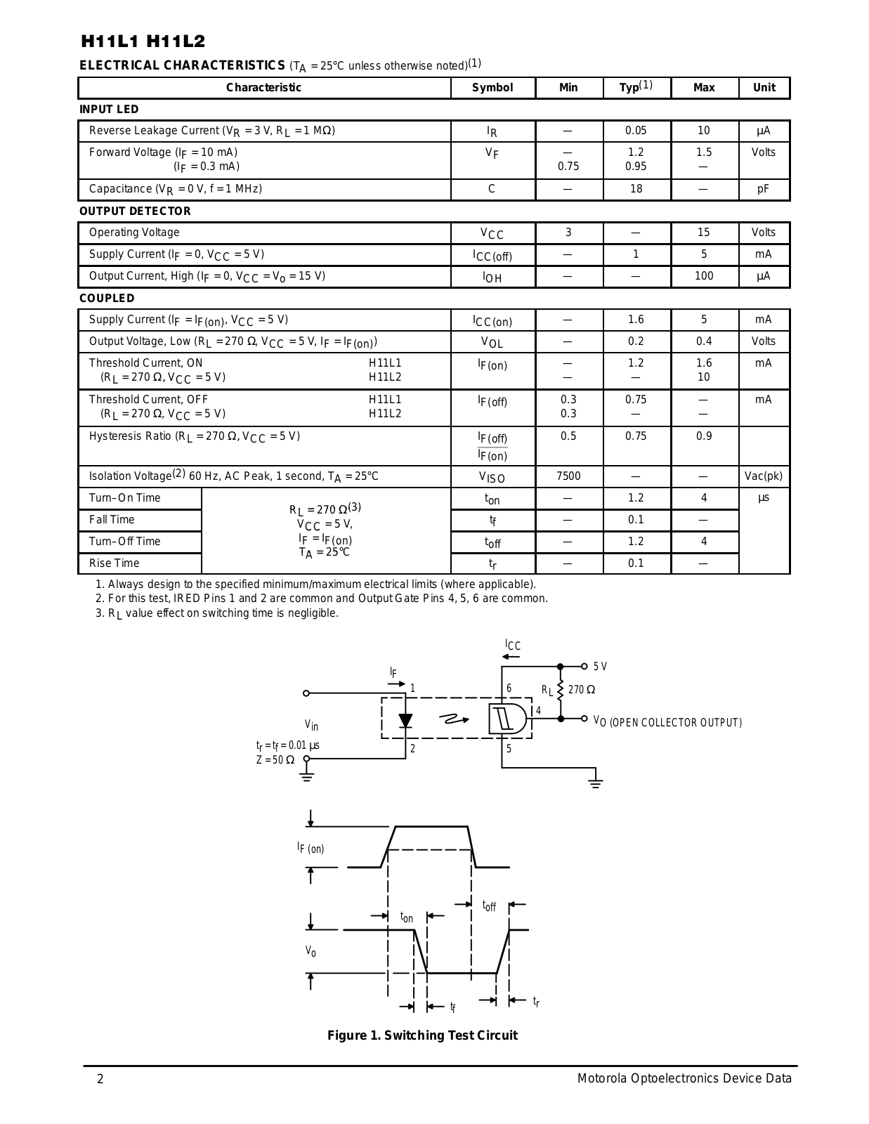
Motorola H11L2, H11L1 Datasheet
...
Motorola Datasheet
Download
Specifications and Main Features
Frequently Asked Questions
User Manual
Download
Loading...
+
4
hidden pages
Unhide
You need points to download manuals.
1 point = 1 manual.
You can buy points or you can get point for every manual you upload.
Buy points
Upload your manuals
 Loading...