


GM160
Motorola GM160, GM340, GM140, GM380, GM360 Service Information
...
Professional Radio
GM Series
UHF (403-470MHz)
Service Information
Issue: August 2002

ii
Computer Software Copyrights
The Motorola products described in this manual may include copyrighted Motorola computer programs stored
in semiconductor memories or other media. Laws in the United States and other countries preserve for
Motorola certain exclusive rights for copyrighted computer programs, including the exclusive right to copy or
reproduce in any form, the copyrighted computer program. Accordingly, any copyrighted Motorola computer
programs contained in the Motorola products described in this manual may not be copied or reproduced in
any manner without the express written permission of Motorola. Furthermore, the purchase of Motorola
products shall not be deemed to grant, either directly or by implication, estoppel or otherwise, any license
under the copyrights, patents or patent applications of Motorola, except for the normal non-exclusive royaltyfree license to use that arises by operation of law in the sale of a product.

iii
Table of Contents
Chapter 1 MODEL CHART AND TECHNICAL SPECIFICATIONS
1.0 GM140/GM160 Model Chart................................................................................1-1
2.0 GM340/GM360/GM380 Model Chart ...................................................................1-1
3.0 GM640/GM660/GM1280 Model Chart .................................................................1-2
4.0 Technical Specifications ......................................................................................1-3
Chapter 2 THEORY OF OPERATION
1.0 Introduction ..........................................................................................................2-1
2.0 UHF (403-470MHz) Receiver .............................................................................2-1
2.1 Receiver Front-End .......................................................................................2-1
2.2 Front-End Band-Pass Filters & Pre-Amplifier.................................................2-2
2.3 First Mixer and High Intermediate Frequency (IF)..........................................2-2
2.4 Low Intermediate Frequency (IF) and Receiver Back End.............................2-2
3.0 UHF (403-470MHz) Transmitter Power Amplifier (PA) 25 W....................2-3
3.1 First Power Controlled Stage..........................................................................2-3
3.2 Power Controlled Driver Stage .......................................................................2-4
3.3 Final Stage......................................................................................................2-4
3.4 Directional Coupler.........................................................................................2-4
3.5 Antenna Switch...............................................................................................2-5
3.6 Harmonic Filter ...............................................................................................2-5
3.7 Power Control.................................................................................................2-5
4.0 UHF (403-470MHz) Frequency Synthesis ..........................................................2-6
4.1 Reference Oscillator.......................................................................................2-6
4.2 Fractional-N Synthesizer ................................................................................2-6
4.3 Voltage Controlled Oscillator (VCO) ...............................................................2-7
4.4 Synthesizer Operation....................................................................................2-8
5.0 UHF (403-470MHz)
Transmitter Power Amplifier (PA) 45 W....................2-9
5.1 Power Controlled Stage..................................................................................2-9
5.2 Pre-Driver Stage .............................................................................................2-9
5.3 Driver Stage..................................................................................................2-10
5.4 Final Stage....................................................................................................2-10
5.5 Directional Coupler.......................................................................................2-10
5.6 Antenna Switch.............................................................................................2-10
5.7 Harmonic Filter .............................................................................................2-10
5.8 Power Control...............................................................................................2-11

iv
Chapter 3 TROUBLESHOOTING CHARTS
1.0 Troubleshooting Flow Chart for Receiver (Sheet 1 of 2) .....................................3-1
1.1 Troubleshooting Flow Chart for Receiver (Sheet 2 of 2) .....................................3-2
2.0 Troubleshooting Flow Chart for 25W Transmitter (Sheet 1 of 3) ......................... 3-3
2.1 Troubleshooting Flow Chart for 25W Transmitter (Sheet 2 of 3) ......................... 3-4
2.2 Troubleshooting Flow Chart for 25W Transmitter (Sheet 3 of 3) ......................... 3-5
3.0 Troubleshooting Flow Chart for 40W Transmitter ...............................................3-6
4.0 Troubleshooting Flow Chart for Synthesizer........................................................3-7
5.0 Troubleshooting Flow Chart for VCO................................................................... 3-8
Chapter 4 UHF PCB/SCHEMATICS/PARTS LISTS
1.0 Allocation of Schematics and Circuit Boards .......................................................4-1
1.1 Controller Circuits ................................................................................................4-1
2.0 UHF 1-25W PCB 8485670z02 / Schematics.......................................................4-3
2.1 UHF 1-25W PCB 8485670z02 Parts List........................................................... 4-10
3.0 UHF 25-40W PCB 8480643z06 / Schematics................................................... 4-13
3.1 UHF 25-40W PCB 8480643z06 Parts List.........................................................4-20
4.0 UHF 1-25W PCB 8485670z03 / Schematics..................................................... 4-23
4.1 UHF 1-25W PCB 8485670z03 Parts List........................................................... 4-30
5.0 UHF 1-25W PCB 8486127z01 / Schematics..................................................... 4-33
5.1 UHF 1-25W PCB 8486127z01 Parts List........................................................... 4-40
Chapter 1
MODEL CHART AND TECHNICAL SPECIFICATIONS
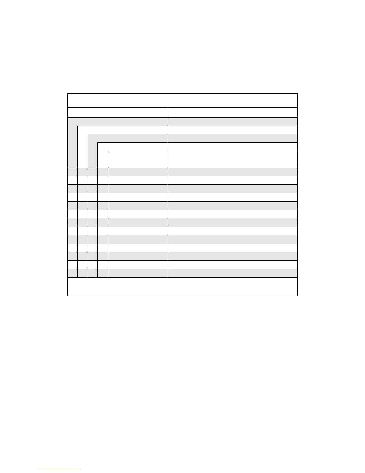
1.0 GM140/GM160 Model Chart
GM Series UHF 403-470 MHz
Model Description
MDM25RKC9AN1_E GM140, 403-470 MHz, 25-40W, 4 Ch
MDM25RKF9AN5_E GM160, 403-470 MHz, 25-40W, 128 Ch
MDM25RHC9AA1_E GM140, 403-470 MHz, 1-25W, 4 Ch
MDM25RHF9AA5_E GM160, 403-470 MHz, 1-25W, 128 Ch
Item Description
X X GCN6112_ Control Head GM140
X X GCN6120_ Control Head GM160
X IMUE6012_ Tanapa, GM140
X IMUE6012_ Tanapa, GM160
X IMUE6021_ Tanapa, GM140
X IMUE6021_ Tanapa, GM160
X X X X ENBN4056_ Packaging, Waris Mobile Radio
XXXXGLN7324_ Low Profile Mounting Trunion
X X HKN9402_ 12V Power Cable, 25-45W
X X HKN4137_ 12V Power Cable, 1-25W
X X X X MDRMN4025_ Enhanced Compact Microphone
X X 6864110B86_ User Guide, GM140
X X 6864110B87_ User Guide, GM160
X = Indicates one of each is required
1-2 MODEL CHART AND TECHNICAL SPECIFICATIONS
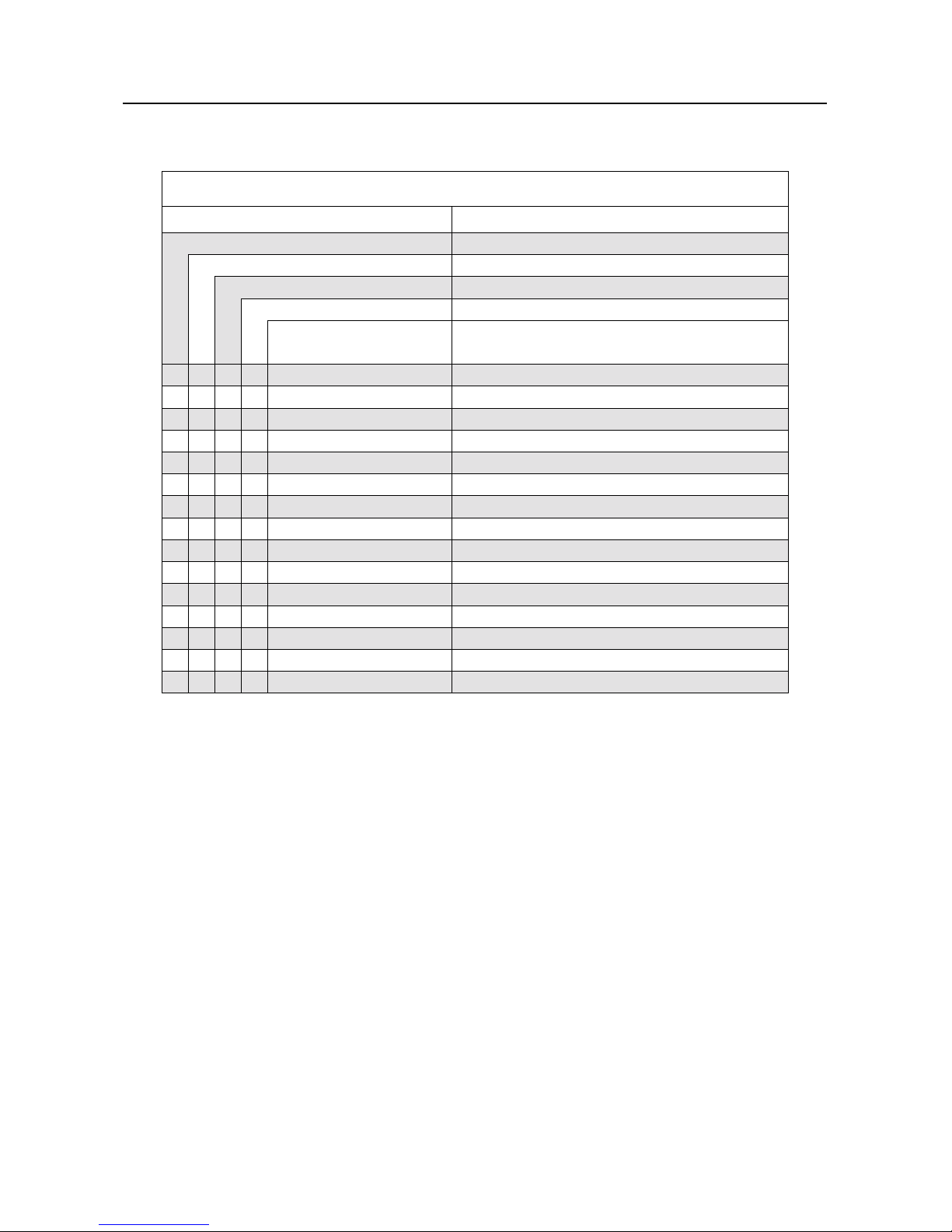
2.0 GM340/GM360/GM380 Model Chart
GM Series UHF 403-470 MHz
Model Description
MDM25RHC9AN1_E GM340, 403-470 MHz, 1-25W, 6 Ch
MDM25RHF9AN5_E GM360, 403-470 MHz, 1-25W, 255 Ch
MDM25RHC9AN8_E GM380, 403-470 MHz, 1-25W, 255 Ch
MDM25RHA9AN0_E Databox, 403-470 MHz, 1-25W, 16 Ch
Item Description
X GCN6112_ Control Head GM340
X GCN6120_ Control Head GM360
X GCN6121_ Control Head GM380
X GCN6116_ Databox Radio Blank Head
X IMUE6015_S Field Replaceable Unit (Main Board) GM340
X IMUE6015_S Field Replaceable Unit (Main Board) GM360
X IMUE6038_S Field Replaceable Unit (Main Board) GM380
X IMUE6015_A S/T 403-470MHz 1-25 SEL5
X X X X ENBN4056_ Packaging, Waris Mobile
XXXXGLN7324_ Low Profile Mounting Trunnion
X X X X HKN4137_ 12V Power Cable 1-25W
X X X MDRMN4025_ Enhanced Compact Microphone
X 6864110B80 User Guide GM340
X 6864110B81 User Guide, GM360
X 6864110B82 User Guide, GM380
X = Indicates one of each is required
GM640/GM660/GM1280 Model Chart 1-3
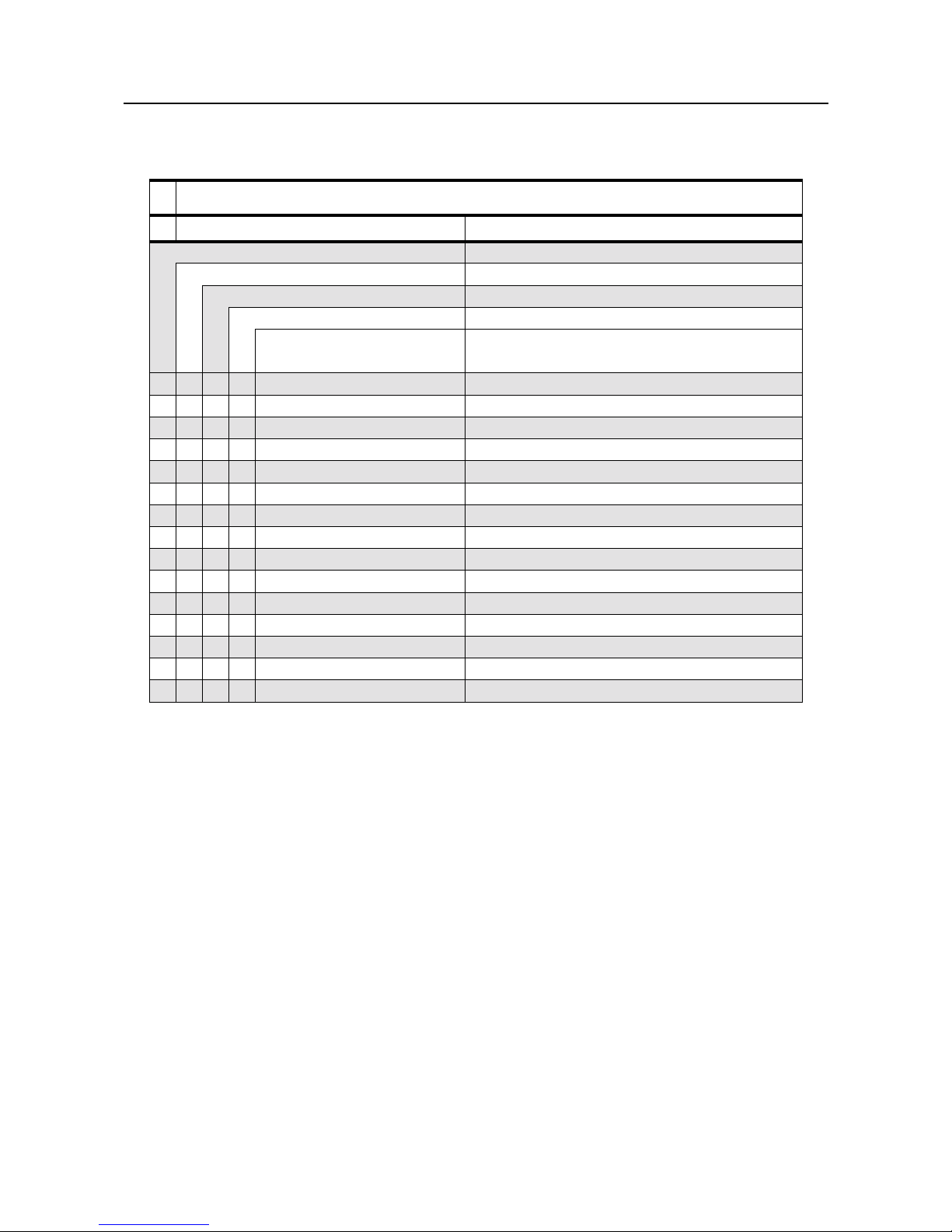
3.0 GM640/GM660/GM1280 Model Chart
GM Series UHF 403-470 MHz
Model Description
MDM25RHC9CK1_E GM640, 403-470 MHz, 1-25W, 6 Ch
MDM25RHF9CK5_E GM660, 403-470 MHz, 1-25W, 255 Ch
MDM25RHN9CK8_E GM1280, 403-470 MHz, 1-25W, 255 Ch
MDM25RHA9CK7_E Databox, 403-470 MHz, 1-25W, 16 Ch
Item Description
X GCN6112_ Control Head GM640
X GCN6120_ Control Head GM660
X GCN6121_ Control Head GM1280
X GCN6116_ Databox Radio Blank Head
X IMUE6009_A S/T 403-470MHz 1-25 SEL5
X IMUE6009_S Field Replaceable Unit (Main Board) GM640
X IMUE6009_S Field Replaceable Unit (Main Board) GM660
X IMUE6009_S Field Replaceable Unit (Main Board) GM1280
X X X X ENBN4056_ Packaging, Waris Mobile Radio
XXXXGLN7324_ Low Profile Mounting Trunnion
X X X X HKN4137_ 12V Power Cable, 1-25W
X X X MDRMN4025_ Enhanced Compact Microphone
X 6864110B83_ User Guide, GM640
X 6864110B84_ User Guide, GM660
X 6864110B85_ User Guide, GM1280
X = Indicates one of each is required
1-4 MODEL CHART AND TECHNICAL SPECIFICATIONS
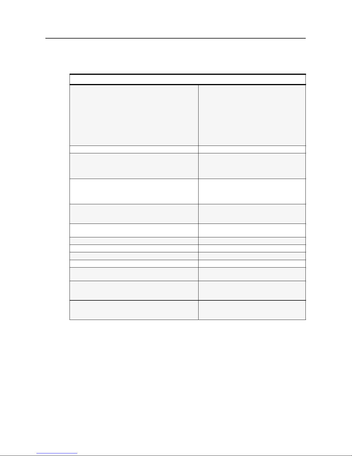
4.0 Technical Specifications
Data is specified for +25°C unless otherwise stated.
General Specifications
Channel Capacity
GM140
GM160
GM340
GM360
GM380
GM640
GM660
GM1280
Databox
4
128
6
255
255
6
255
255
16
Power Supply 13.2Vdc (10.8 - 15.6Vdc)
Dimensions: H x W x D (mm) Depth excluding knobs GM140/340/640
56mm x 176mm x 177mm (1 - 25W)
56mm x 176mm x 189mm (25 - 40W)
(add 8mm for Volume Knob)
Dimensions: H x W x D (mm) Depth excluding knobs GM160/360/660
59mm x 179mm x 186mm (1 - 25W)
59mm x 179mm x 198mm (25 - 40W)
(add 9mm for Volume Knob)
Dimensions: H x W x D (mm) Depth excluding knobs GM380/1280
72mm x 185mm x 188mm
(add 8mm for Volume Knob)
Dimensions: H x W x D (mm) Depth excluding knobs Databox
44mm x 168mm x 161mm
Weight GM140/340/640 1400gr
Weight GM160/360/660 1400gr
Weight GM380/1280 1500gr
Weight Databox 1220gr
Sealing: Withstands rain testing per
MIL STD 810 C/D /E and IP54
Shock and Vibration: Protection provided via impact
resistant housing exceeding MIL STD
810-C/D /E and TIA/EIA 603
Dust and Humidity: Protection provided via environment
resistant housing exceeding MIL STD
810 C/D /E and TIA/EIA 603
Technical Specifications 1-5
*Availability subject to the laws and regulations of individual countries.
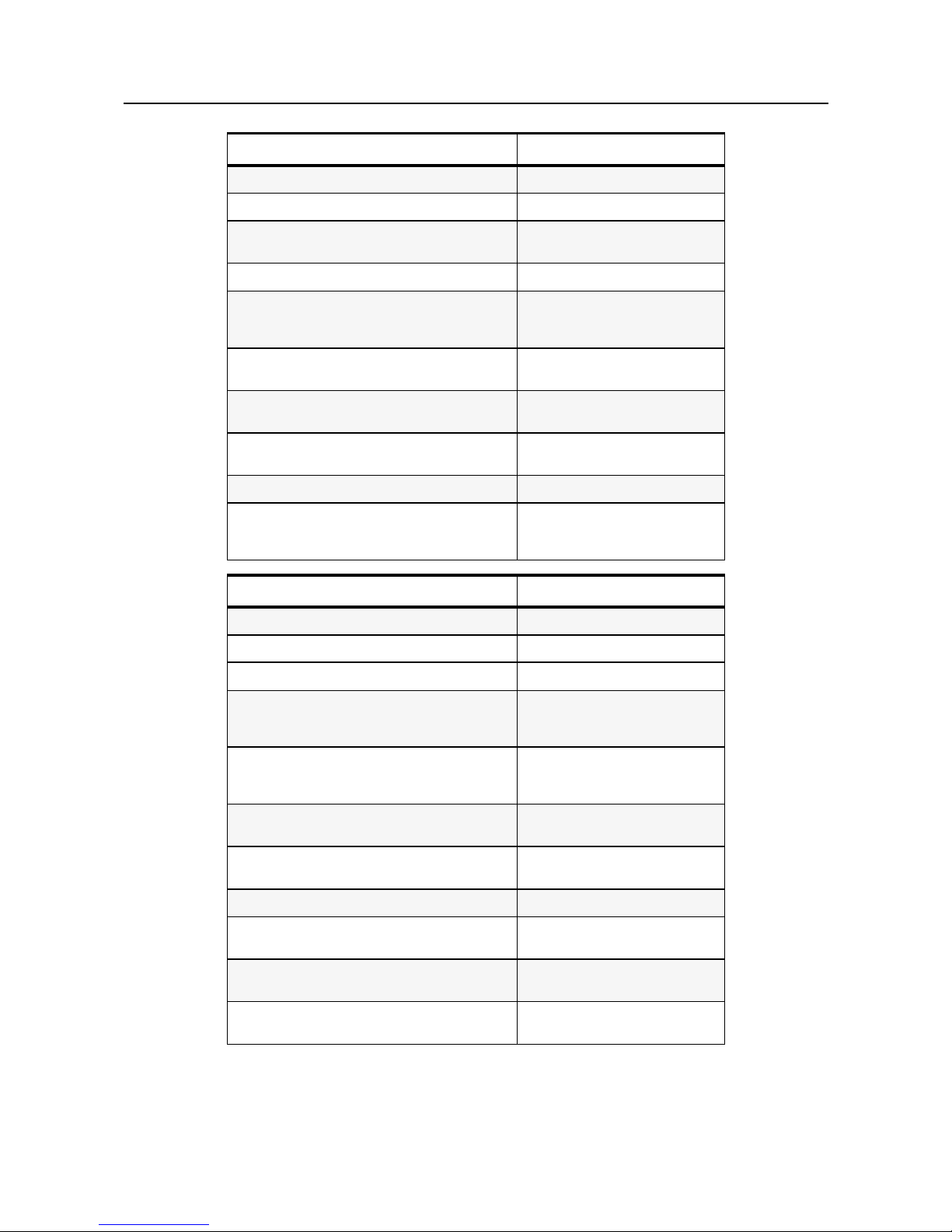
Transmitter UHF
*Frequencies - Full Bandsplit UHF 403-470 MHz
Channel Spacing 12.5/20/25 kHz
Frequency Stability
(-30°C to +60°C, +25° Ref.)
±2.0 ppm
Power 1-25W/25-40W
Modulation Limiting
±2.5 @ 12.5 kHz
±4.0 @ 20 kHz
±5.0 @ 25 kHz
FM Hum & Noise
-40 dB @ 12.5kHz
-45 dB @ 20/25kHz
Conducted/Radiated Emission (ETS)
-36 dBm <1 GHz
-30 dBm >1 GHz
Adjacent Channel Power
-60 dB @ 12.5 kHz
-70 dB @ 25 kHz
Audio Response (300 - 3000 Hz) +1 to -3 dB
Audio Distortion
@1000Hz, 60%
Rated Maximum Deviation
<3% typical
Receiver UHF
*Frequencies - Full Bandsplit UHF 403-470 MHz
Channel Spacing 12.5/20/25 kHz
Sensitivity (12 dB SINAD) 0.30 µV (0.22 µV typical)
Intermodulation (ETS)
>65 dB
Base Mode: >70dB
(1-25W model only)
Adjacent Channel Selectivity (ETS)
65 dB @ 12.5 kHz
70 dB @ 20 kHz
75 dB @ 25 kHz
Spurious Rejection (ETS)
70 dB @ 12.5 kHz
75 dB @ 20/25 kHz
Rated Audio
3W Internal
13W External
Audio Distortion @ Rated Audio <3% typical
Hum & Noise
-40 dB @ 12.5 kHz
-45 dB @ 20/25 kHz
Audio Response (300 - 3000Hz @ 20/25kHz)
(300 - 2550Hz @12.5kHz)
+1 to -3 dB
Conducted Spurious Emission (ETS)
-57 dBm <1 GHz
-47 dBm >1 GHz

1-6 MODEL CHART AND TECHNICAL SPECIFICATIONS
 Loading...