


MANUAL No. 99MBE021A
SERIES No. 264
Digimatic Mini-Processor
User's Manual
In order to obtain the best possible performance from the Mitutoyo
Digimatic Mini-Processor DP-1VR,
read this user’s manual thoroughly before operation.
After reading, retain it close at hand for future reference.
DP-1VR

i
THE MARKS USED IN USER'S MANUAL
The meaning of symbol mark and contents describe with each symbol mark used
in users manual is as follow.
Notice on Safety
In user's manual, to use exactly this unit, and to protect from yours and other
peoples damage and property, several chart expression. The expression and
meaning are as follows.
● Following expressions shown general notices, cautions and dangers, but not
limited.
Neglecting this expression, if you deal with this unit by incorrect way, it
will be imminent occurrence of human death or heavy injury.
Neglecting this expression, if you deal this unit by incorrect way, it will be
supposed to occur possibility of human death or heavy injury.
Neglecting this expression, if you deal with this unit by incorrect way, it
will be supposed to occur possibility of human damage and physical
damage.
ii
THE MARKS USED IN USER'S MANUAL
● The following marks show notice, exhibit of action/compulsion
This marks show that there is contents urge the notice (include danger,
warning. In the chart, concrete notice meaning is shown (left chart mean
electrical shock)
This mark express exhibited action. Concrete exhibited actions are drawn
in the charts or near the charts. (left chart means exhibit of disassemble)
This mark express the action under compulsion or direction. Concrete
directed actions are drawn in the charts or near the charts. (left chart
shows necessity of earth)

iii
Important
Notice
Reference
When any damages happen by the method not to depend on this
manual, our company does not have any responsibilities.
Contents of this manual may be changed without advance notice.
(c) Copyright Mitutoyo Corporation. All rights reserved.
THE MARKS USED IN USER'S MANUAL
About several kinds of notice.
Several kinds of "notice" which assist to obtain high reliable measured data
show in following words.
◆ Notice indicates necessary information to achieve the purpose.
Do not neglect this direction.
◆ If you do not follow this direction, there are the possibilities to loss
or difficult to maintain the performance and accuracy of this unit.
This word indicates especially emphasize or supplementary information.
It shows that there are attentions for specified operation (limit of
memory, construction of equipment, information concerned with
special version of program. etc.)
This word indicates reference information concerned with operating
method and procedure described in this manual to apply for particular problem or details explanation of operation and function.
And if there are other reference informations, they may be shown the
reference portion

iv
NOTICE ON SAFETY (PLEASE READ SURELY)
To use safely, you should observe following.
◆ This unit is intended to be used for a general equipment (measuring
equipment, or machine tool etc.) Do not use this unit for medical
machine, aerospace vehicle, train or atomic power etc. which miss
operation of this unit have possibility to injure the human body or
treated human life. When you intend to use for such purpose, please
inform to our company in advance.
◆ If accidents happen such as smoke, curious smell or abnormal
operation, cut power and pullout AC adapter from consent, then
inform to service network. If you continue operation, it causes fire or
electric shock.
◆ When you drop this unit and it is damaged, cut power and pullout AC
adapter from consent, then inform to service network. If you continue
operation, it causes fire or electric shock.
◆ Do not repair or modify this unit by user. As it causes fire or electric
shock, do not implement absolutely.
◆ When foreign object puts into this unit, cut power and pullout AC
adapter from consent, then inform to service network.

v
NOTICE ON SAFETY (PLEASE READ SURELY)
◆ Please keep specified power source voltage. When this unit is used
with not specified power source voltage. it causes damage of inside,
fire or electric shock.
◆ Please do not put this unit at the place opened to direct sunshine or
hot temperature. Inner temperature of this unit increases and causes
fire.
◆ Do not put this unit close to wall. Inner temperature increases and
causes malfunction. And also please put this unit apart about 10 cm
from wall as you can pullout the cord of power source without moving
this unit.
REGARDING TO EC COMMAND CONFORMITY
◆ This unit is conformed to following EC Command.
EMC Command EN61326-1997+A1:1998

vi
CONTENTS
The marks used in this user's manual........................................................................... i
Notice on Safety (Please read thoroughly) ................................................................ iv
WARRANTY ............................................................................................................. vi
1. OUTLINE........................................................................................................ 1
1. Introduction ........................................................................................................... 1
2. Features .................................................................................................................. 1
2. SET UP .......................................................................................................... 3
1. Power supply ......................................................................................................... 3
1.1 Setting the battery ......................................................................................... 3
1.2 Connection of the AC adapter ....................................................................... 5
2. Set of recording paper............................................................................................ 6
3. Connection of the measuring tool .......................................................................... 7
4. Other connection.................................................................................................... 8
4.1 Attachment of strap....................................................................................... 8
4.2 Footswitch..................................................................................................... 9
4.3 RS-232C Cable • GO±NG judgement cable................................................. 9
4. PARAMETER ............................................................................................... 10
1. Parameter ............................................................................................................. 10
2. In the case of connecting caliper micrometer ...................................................... 10
3. In the case of printout of RS232C linearscale output .......................................... 12
4. Example of parameters setting ............................................................................ 15
4.1 DP-1 parameter setting procedure .............................................................. 15
5. SUMMARY OF FUNCTIONS....................................................................... 19
1. Key functions....................................................................................................... 19
2. Function of each mode ........................................................................................ 20
3. Timer input function ............................................................................................ 21
6. OPERATION ................................................................................................ 22
1. Power ON/OFF .................................................................................................... 22
2. Basic Operation 1 ................................................................................................ 23
2.1 Data input, cancel, clear..............................................................................23

vii
CONTENTS
3. Basic operation 2 ................................................................................................. 25
3.1 Input of tolerance limit data........................................................................ 25
3.2 Confirmation/renew of limit data ............................................................... 27
3.3 Release of limit data ................................................................................... 28
3.4 Data input, cancel, clear..............................................................................29
4. Mode 3 ................................................................................................................. 32
5. Print RS232C of counter...................................................................................... 34
6. OTHER NOTICES ........................................................................................ 36
7. MAINTENANCE........................................................................................... 37
1. Clean printer head ................................................................................................ 37
2. Clean paper sensor ............................................................................................... 37
8. ERROR MESSAGE...................................................................................... 39
1. Alarms concerning electric power ....................................................................... 39
2. Other alarms ........................................................................................................ 40
9. CALCULATION METHOD ........................................................................... 42
1. Significant figure ................................................................................................. 42
2. Overflow and calculation tolerance ..................................................................... 43
3. Calculation tolerance detail ................................................................................. 44
4. Calculation formula ............................................................................................. 45
4.1 Calculation of Mode1, Mode2 .................................................................... 45
4.2 Calculation Mode3......................................................................................46
10. OUTPUT....................................................................................................... 47
1. Output of GO/±NG Judgment Result .................................................................. 47
2. Output in Accordance with RS-232C Format...................................................... 47
2.1 Communication Specifications ................................................................... 48
2.2 Data Format ................................................................................................ 48
2.3 Error Code .................................................................................................. 49
2.4 Data request command................................................................................ 49
11. TROUBLESHOOTING................................................................................. 50
12. SPECIFICATIONS ....................................................................................... 52
SER VICE NETWORK .................................................................................. 54

- 1 -
OUTLINE
1
1. Introduction
DV-1VR is an exclusive piece of data processing equipment that records data from a
Mitutoyo digimatic tool so it can be statistically processed operation is easy and
statistical results can be obtained quickly.
2. Features
(1) Abundant statistical parameters:
Number of samples (N) • Maximum value (MAX) • Minimum value (MIN) •
Range (R) • Mean value (X) • Standard deviation (σ-n, σn-1) • Process capability
index (C
P, CPK) • Number of defects (±NG) • Percent detective (P)
Limit data 5 types
(2) Preparation of histogram
(3) Preparation of a chart of displacement that expresses the time history of mea-
sured data D (Displacement).
(4) Several calculation functions necessary to prepare the X-R control chart.
(5) Timer input function.
(6) Data output function.
Output of measured data (RS-232C, TTL Level)
Output result of success or failure (+NG, GO, −NG)
It can be connected to Mitutoyo Instrument Network System (µNET System)
(7) Output of success or failure by LED.
(8) Power source system of AC adapter or four AA type Nickel Hydrogen batteries
(Ni-MH)/Alkali batteries (LR6)
(9) Standard equipment of 48 m recording paper.
OUTLINE
- 2 -
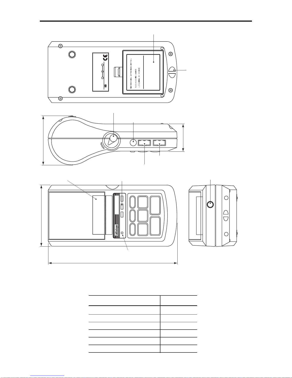
External view
Parts List
Parts name Quantity
DP-1VR (Main unit) 1
AC adapter 1
Recording paper 1
Strap 1
Quick reference 1
User’s manual 1
Must use the following types of battery
for battery operation.
Alkaline battery LR6
AA Ni-MH battery
+ −
Mitutoyo Corporation
MADE IN JAPAN
Code No.
Model
Serial No.
Power
INPUT OUTPUT ADAPTER
OPEN
POWER
POWER
−
NG
PRINTER CL
CESTAT
FEED DATA
TOL.
LIMIT
GO
+
NG
DIGIMATIC MINI-PROCESSOR
EXT.P
75.2
43.9
94
201.1
Foot switch connector
GO/±NG LED
Adapter jack
Release lever
Strap attachment
Battery box
Output connector
Input connector
Power source LED
Recording paper cover/
Recording paper
- 3 -
SET UP
2
1. Power supply
● Power is supplied to this unit by the AC adapter or four AA type Nickel Hydrogen
batteries (Ni-Mh)/Alkali batteries (LR6)
● When the AC adapter is used while batteries installed, the power will be supplied
from the AC adapter (batteries are not included). The AC adapter cannot charge the
batteries, charge them with a dedicated battery charger, if necessary.
● When a voltage drop occurs when using the battery or AC adapter, the power
source LED will blink and show an abnormal condition.
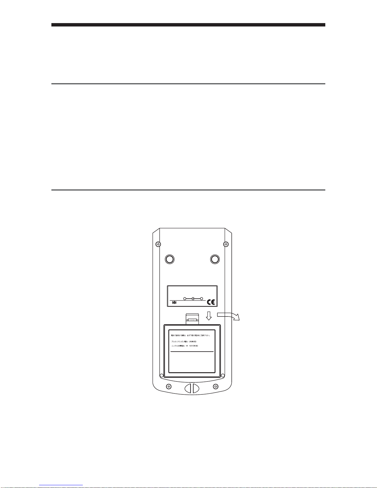
1.1 Setting the battery
Set the batteries. If using the AC adapter, refer to section 1.2
qq
qq
q Open the battery box.
Must use the following types of battery
for battery operation.
Alkaline battery LR6
AA Ni-MH battery
+ −
Mitutoyo Corporation
MADE IN JAPAN
Code No.
Model
Serial No.
Power
Push down the stopper of the battery box and pull forward.

- 4 -
SET UP
ww
ww
w Set the batteries.
Be sure to set correctly the poles of the size AA Alkali batteries (LR6) or Nickel
Hydrogen batteries (Ni -MH AA)
e Close the battery box by the inverse process of q firmly until you hear the
clicking sound.
IMPORTANT
◆ Set the poles of batteries correctly.
◆ Do not use different kinds of batteries.
◆ Use either size AA Alkali batteries (LR6) or AA Nickel Hydrogen batteries
(Ni-MH AA)
◆ Manganese batteries R6 cannot be used.
◆ When Alkali batteries are used, printed letters may fade accordingly.
◆ When Alkali batteries or Nickel Hydrogen batteries are used, print speed is
slower compared with the AC adapter.
◆ In the case of using batteries, if the surface shows peeling or breaks on the pole
of the battery, it may cause poor contact and start-up. Please use batteries only
after you check there is no peeling or surface breaks on the poles of batteries.
◆ If DP-1VR is not used for a long period, please remove the batteries from DP-
1VR. If the batteries remain connected to the DP-1VR for long time, fluid
leakage may damage the DP-1VR.
◆ The operational temperature of the batteries must remain over 10°C. If the
temperature is less than 10°C, undesirable things, such as printed letters
become thin, etc., may occur.
- 5 -
SET UP
NOTE
◆ DP-1VR has no charger function. If you need to charge the batteries, a
dedicated battery charger is needed.
◆ Battery life is about 10,000 lines, (using 1,600 m Ah Ni-MH, and print large,
letter one time per 5 sec.)
◆ Battery life varies drastically in accordance with environmental conditions.
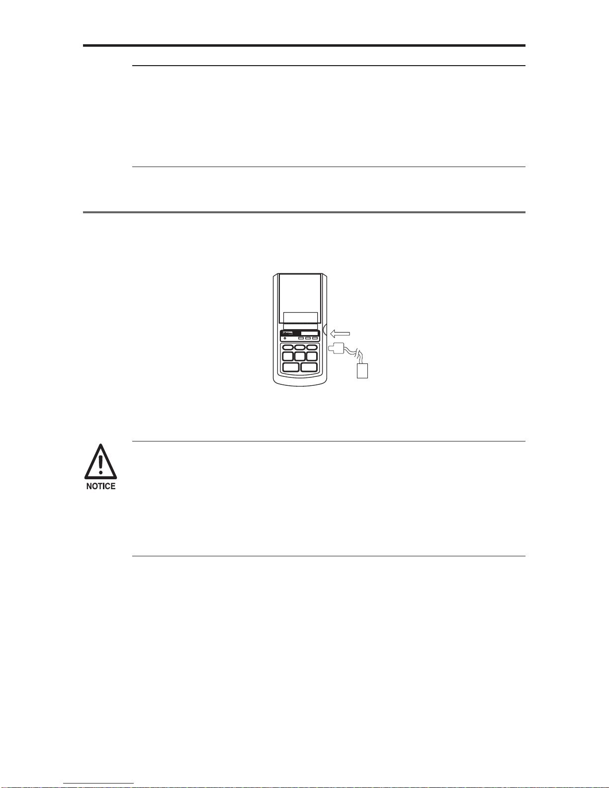
1.2 Connection of the AC adapter
Connect the AC adapter to the DP-1VR.
Skip this page when using batteries.
POWER
POWER
−
NG
PRINTER CL
CESTAT
FEED DATA
TOL.
LIMIT
GO+NG
DIGIMATIC MINI-PROCESSOR
Insert firmly all the way.
◆ The AC adapter specified by our company should be used.
100/115V 09EAA088
230V 09EAA088D
230V UK 09EAA088E
◆ If the specified AC adapters are not used, print quality and life expectancy will
be reduced.

- 6 -
SET UP
2. Set of recording paper
q
OPEN
● Push the release lever downward
● Move the cover of recording paper upward, then open it.
w
● Peel tape fixing the edge of record paper, then set the recording paper with a little
bit of the paper pulled out.
● Set the core of the recording paper firmly in the holder. If the recording paper is
wrinkled, it can cause the paper to jam while printing, so be sure it is straight.
● Close the cover of the recording paper, pulling out the edge the recording paper a
little bit.
● Press the ‘power’ key to power ON and press the ‘FEED’ key, to send out the
recording paper about 100 mm.
- 7 -
SET UP
• Be careful to connect the connector correctly.
• Pull and put the connector in straight.
● When paper is set, be careful not to injure your hand by the paper cutter.
IMPORTANT
◆ After setting the recording paper, be sure to press the ‘FEED’ key. This will
perform a self-alignment thereby reducing paper jamming.
◆ When you open the recording paper cover, the printer head is exposed.
Immediately after printing, the printer head is hot. Do not touch to avoid being
burned.
◆ DP-1VR recording paper has superior characteristic of conservation, tolerance
to chemicals and weather-proof. Please use the recording paper specified by
our company. (Part No. 09EAA082 10 roll pack)
◆ Print quality is not guaranteed if the specified recording paper is not used.
◆ Recording paper should be stored in a cool and dark place.
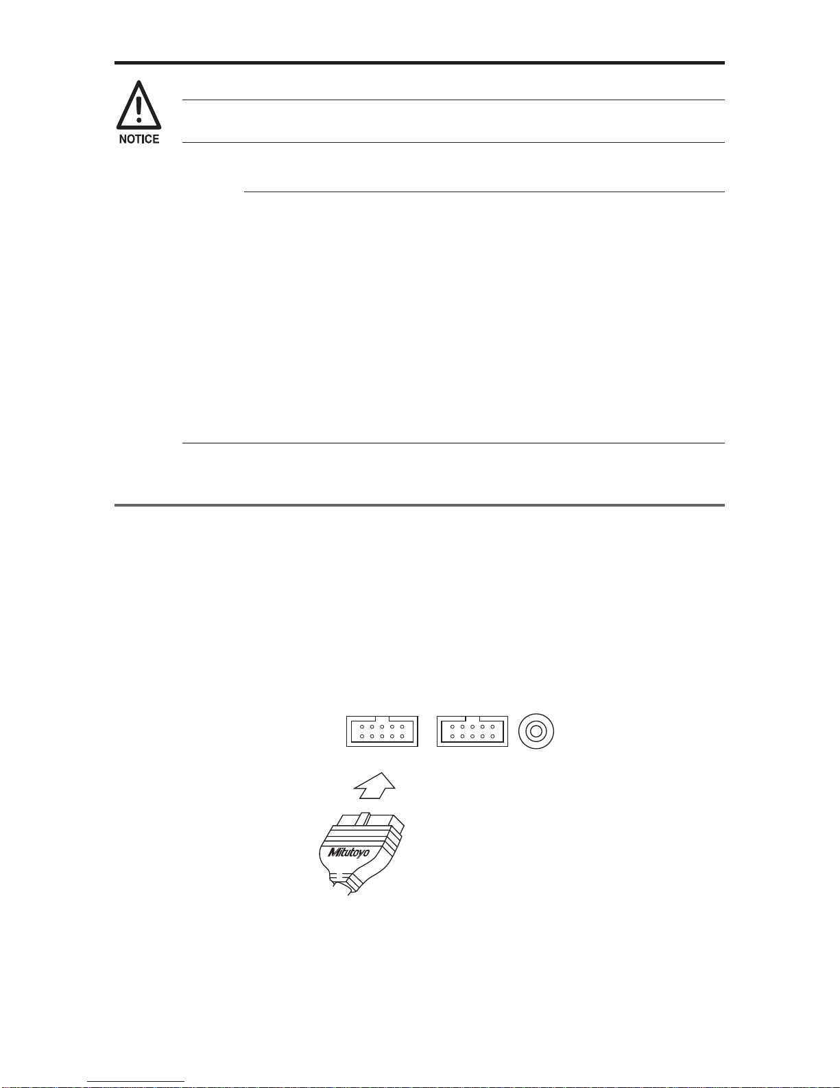
3. Connection of the measuring tool
Before connection, confirm that electric power to the digimatic measuring tool is OFF.
(1) Connection to the digimatic measuring tool.
Connect one connector of the connecting cable to DP-1VR input connector and the
other connector to the output connector of the digimatic measuring tool. Some con-
necting cables are different, depending on the type of measuring tool, please refer
to each user's manual.
OUTPUTINPUT
Connection of the input connector

- 8 -
SET UP
4. Other connection
4.1 Attachment of the strap
Attach the strap to the DP-1VR as necessary
q Take the sling off the hook.
w Press the sling through the attachment point of the DP-1 as shown in the figure.
Must use the following types of battery
for battery operation.
Alkaline battery LR6
AA Ni-MH battery
Insert strap here
Sling
Hook
e Hang the hook on the ring and pull out.
- 9 -
SET UP
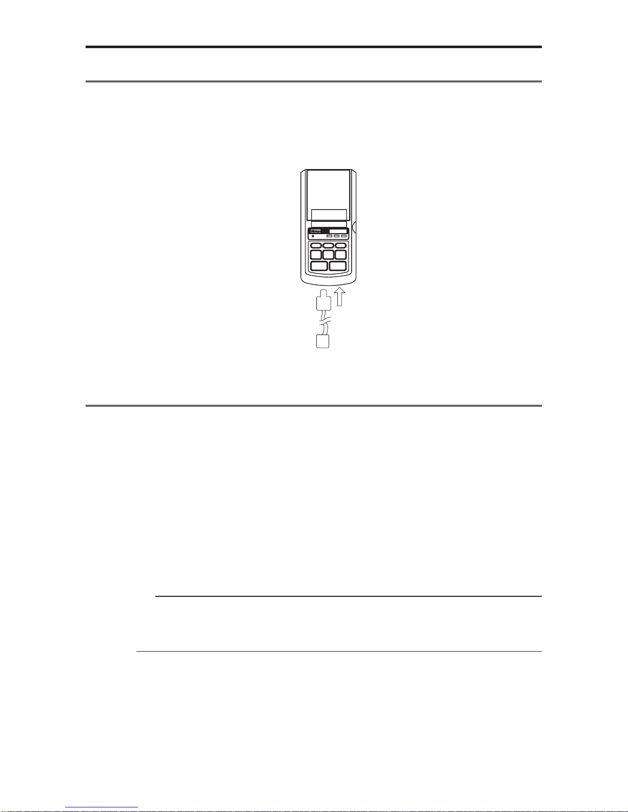
4.2 Footswitch
Data can be input by a foot switch.
Connect to a foot switch connector, part No. 937179T (optional accessory)
POWER
POWER
−
NG
PRINTER CL
CESTAT
FEED DATA
TOL.
LIMIT
GO+NG
DIGIMATIC MINI-PROCESSOR
4.3 RS-232C Cable • GO±NG judgement cable
q RS-232C cable (part No. 09EAA084)
RS-232C output can be obtained from DP-1VR and used for printing RS-232C,
output of a linear scale counter. Connect the RS-232C cable to the DP-1VR output
connector.
w GO±NG judgment cable (part No. 965516)
The results of a judgment can be obtained from the DP-1VR. Connect it to output
connector of the DP-1VR.
NOTICE
The RS-232C cable and GO±NG judgment cable can not be used simultaneously.
Be sure to connect / disconnect the cables only when the power is OFF.

- 10 -
PARAMETER
3
1. Parameter
Parameter functions can customize the actions of the DP-IVR. Set up in accordance
with the purpose.
There are two kinds of parameter settings in accordance with connecting measuring
equipment to DP-1VR.
Select parameters in accordance with the measuring equipment used.
2. In the case of connecting calipers or micrometers
Parameters are established for digimatic interfaces such as calipers or micrometers
when connected to DP-1VR.
Start parameter setting mode by pushing the 'DATA' key and 'POWER' key simulta-
neously.
After parameter mode is started, parameters are printed in order. When you want to
change a setting, push the 'STAT' key and when you don't want to change a setting,
push the 'DATA' key; then the parameter will be set.
Next, a table of parameters is shown.

- 11 -
PARAMETER
Table 1 Parameter in DP-1 MODE
-rO
red
metIgnitteSnoitareporetnirPtluafeD
1
-TEMARAP
RAELCRE
raelcretemaraP
RAELCRETEMARAP
RAELCONRETEMARAP
raelctonoD
sretemarap
2
METSYS
EDOM
itluM/edom1-PDteS 1-PD edom 1-PD
3
KROW
EDOM
/1EDOM/0EDOM
3EDOM/2EDOM
1EDOM/0EDOM
3EDOM/2EDOM
1edoM
4
DUAB
ETAR
/0084/0042/0021
00291/0069
0084/0042/0021
00291/0069
0084
5
YTIRAP
ddO/nevE/enoN
DDO/NEVE/NON
NEVE
6
ATAD
HTGNEL
8/7
8/7
7
7
TNIRP
EZIS
lamroN/egraL
LAMRON/EGRAL
EGRAL
si2edomnehW
lamronylnotes
siezisgnitnirp
elbaliava
8
REWOP
EVAS
lamroN/evasrewoP
LAMRON/EVAS
lamroN
9
TNIRP
YTISNED
kraD/lamroN
KRAD/LAMRON
lamroN
01
EDOMZB
FFO/NOedomZB
FFO/NO
NO
11
EMIT
TNIRP
FFO/NOTNIRPEMIT
FFO/NO
21
ATAD
TAMROF
TAMROFETAD
DD/MM/YYYY
YYY/DD/MMM
YYY/MMM/DD
DD/MM/YYYY
31
ATAD
GNITTESETADgnitnirpnehW.g.e ,2.naJ
0002 tamrofatadgnisu
.21nidenifedgnittes
2/1/0002
0002/2/NAJ
0002/NAJ/2
dradnatSnapaJ
emiT
41
EMIT
GNITTESEMITdradnatSnapaJ
emiT
51
TINU
)hcni/mm(citamotuA
retemilliM
hcnI
enoN
marG
edargitneC
noT
ecnuO
hcni/mm
mm
hcni
g
C°
t
.bL
citamotuA
 Loading...