


Mitsubishi PK-2.5FLD, PK-2.5FLD1, PK-2.5FLD2, PK-3FLD, PK-3FLD1 Service Manual
...SPLIT-TYPE, AIR CONDITIONERS |
2000 |
|
|
|
No. OC232 |
|
REVISED EDITION-A |
TECHNICAL & SERVICE MANUAL |
|
Series PK |
Wall Mounted |
|
Indoor unit |
|
|
[ Model names ] |
[ Service Ref. ] |
|
2000, 2001 |
2000 |
2001 |
PK-2.5FLD |
PK-2.5FLD PK-2.5FLD |
|
|
|
1 |
|
|
PK-2.5FLD |
|
|
2 |
PK-3FLD |
PK-3FLD |
PK-3FLD |
|
|
1 |
|
|
PK-3FLD |
|
|
2 |
PK-4FLSD |
PK-4FLD |
PK-4FLSD |
|
|
1 |
PK-4FLSD2
PK-P2.5FLD1, PK-P3FLD1, PK-P4FLSD1, PK-P2.5FLD2, PK-P3FLD2 and PK-4FLSD2 are added in REVISED EDITION-A.
Please void OC232.
This manual does not cover the following outdoor units. When servicing them, please refer to the service manual No.OC127 REVISED EDITION-A, OC187 and this manual in a set.
[ Service Ref. ] (OC127 REVISED EDITION-A)
PU-2.5VJA2, PU-2.5NJA1, PU-3NJA1, PU-4VLJSA2, PU-4YJSA3, PU-4TJSA2 (OC187)
PU-3VJC, PU-3YJC
Indoor unit
 ˚C
˚C
AM
PM
AM
PM
NOT AVAILABLE
ON / OFF
TEMP
PK-2.5FLD, PK-2.5FLD1 PK-3FLD, PK-3FLD1 PK-4FLSD, PK-4FLSD1
PK-2.5FLD2 PK-3FLD2 PK-4FLSD2
REMOTE CONTROLLER
CONTENTS
1.TECHNICAL CHANGES··········
2.COMBINATION OF INDOOR
AND OUTDOOR UNITS·····
3.PART NAMES AND FUNCTIONS ·····
4.SPECIFICATIONS············
5.DATA ··················
6.OUTLINES AND DIMENSIONS·······
7.WIRING DIAGRAM············
8.REFRIGERANT SYSTEM DIAGRAM ·····
9.OPERATION FLOW-CHART ········
10.MICROPROCESSOR CONTROL······
11.TROUBLESHOOTING ··········
12.DISASSEMBLY PROCEDURE ·······
13.PARTS LIST···············
14.OPTIONAL PARTS ············
1 
 TECHNICAL CHANGES
PK-2.5FLD PK-2.5FLD1
PK-3FLD PK-3FLD1
PK-4FLSD PK-4FLSD1
●NOSE has changed by changing its shape.
●BOX ASSEMBLY has changed by changing its shape.
●CENTER SUPPORT has changed by changing its shape.
●DRAIN PAN has changed by changing its shape.
PK-2.5FLD1 PK-2.5FLD2
PK-3FLD1 PK-3FLD2
PK-4FLSD1 PK-4FLSD2
●The parts No. of REMOTE CONTROLLER has changed. (The following parts numbers are interchangeable.)

 ˚C
˚C
AM
PM
AM
PM
ON / OFF
TEMP
[ T7W 570 200 ] [ T7W E06 714 ]
2 
 COMBINATION OF INDOOR AND OUTDOOR UNITS
|
|
|
|
Outdoor unit |
|
|
|
Outdoor unit |
||
Indoor unit |
|
(OC127 REVISED EDITION-A) |
|
(OC187) |
||||||
|
|
|
|
|
|
|
|
|
|
|
PU-2.5 |
PU-3 |
|
PU-4 |
|
PU-3 |
|||||
|
|
|
||||||||
|
VJA2 |
|
NJA1 |
NJA1 |
VLJSA2 |
YJSA3 |
|
TJSA2 |
VJC |
YJC |
PK-2.5FLD |
|
|
|
— |
— |
— |
|
— |
— |
— |
PK-2.5FLD1 |
|
|
|
|
||||||
PK-2.5FLD2 |
|
|
|
|
|
|
|
|
|
|
PK-3FLD |
|
|
|
|
|
|
|
|
|
|
PK-3FLD1 |
— |
|
— |
|
— |
— |
|
— |
|
|
PK-3FLD2 |
|
|
|
|
|
|
|
|
|
|
PK-4FLSD |
|
|
|
|
|
|
|
|
|
|
PK-4FLSD1 |
— |
|
— |
— |
|
|
|
|
— |
— |
PK-4FLSD2 |
|
|
|
|
|
|
|
|
|
|
3 
 PART NAMES AND FUNCTIONS
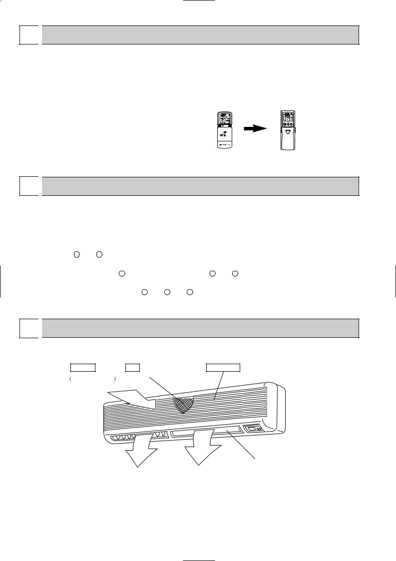
Indoor Unit
Air intake |
Filter |
Air intake grille |
Room air is suctioned |
(Removes dust and dirt from the intake air.) |
|
|
in here. |
|
Guide vane |
|
|
|
Swing louvers |
|
||
|
|
|
|
|
|
||
Air flow can be changed to horizontally |
|
|
Disperses airflow up and |
||||
by moving the Guide vane to the left or |
|
|
down as well as adjusts the |
||||
right. |
|
|
angle of air flow direction. |
||||
|
|
|
|
|
|
|
|
|
|
Air outlet |
|
Air outlet |
|
|
|
|
|
|
|
|
|
|
|
2
PK-2.5FLD, PK-3FLD, PK-4FLSD PK-2.5FLD1, PK-3FLD1, PK-4FLSD1
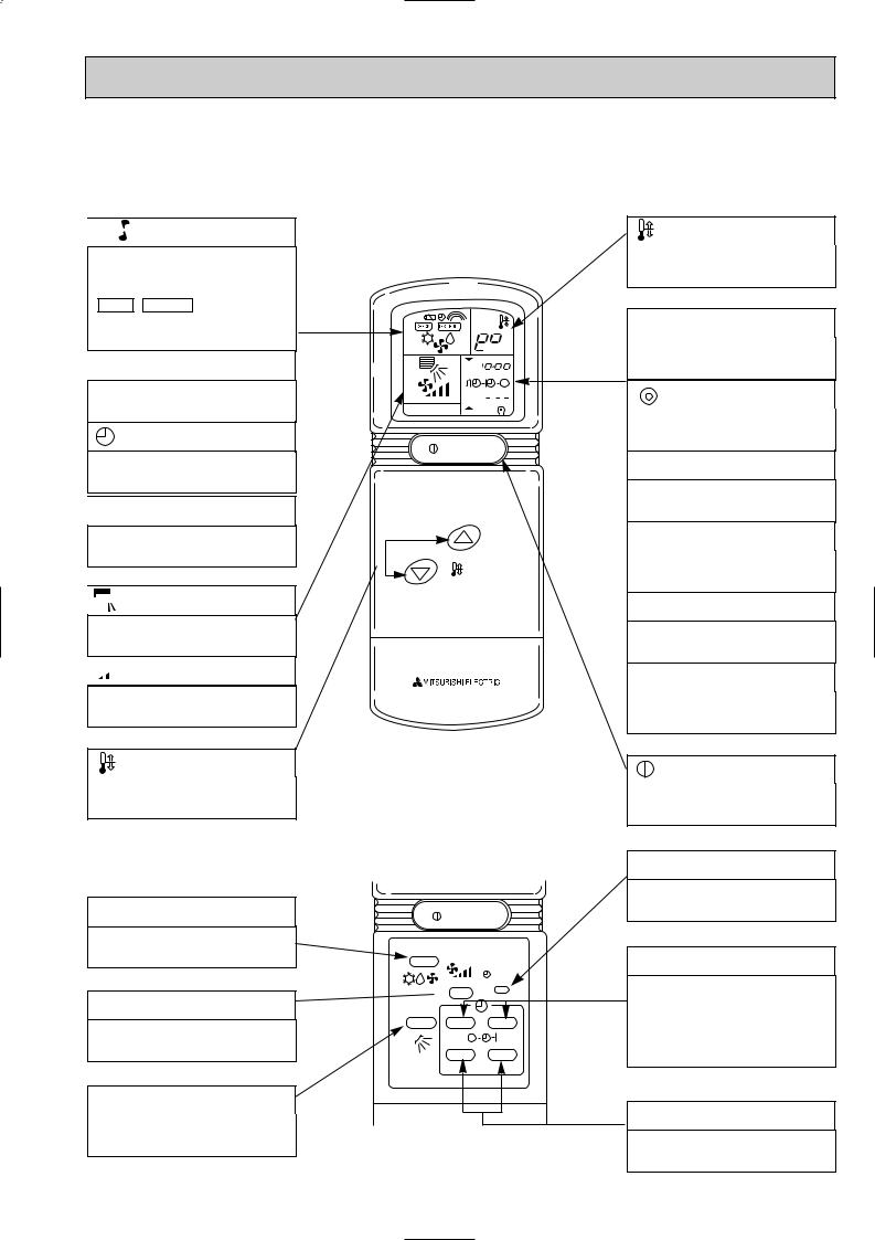
●Wireless remote controller
●When cover is closed.

 display
OPERATION MODE display
Operation mode display indicates which operation mode is in effect.
• CHECK • TEST RUN display
CHECK&TEST RUN display indicates that the unit is being checked or test-run.

 display
Displays when batteries are dead.
display
Displays when setting timer.

 display
Lights when signal is sent from the remote controller to the indoor unit.


 display
The vertical direction of airflow is indicated in ▼ marks.


 display
FAN SPEED display indicates which fan speed has been selected.
button

 ˚C
˚C
AM
PM 


AM 


 PM
PM 


NOT AVAILABLE
ON / OFF
TEMP
SET TEMPERATURE button sets any desired room temperature.
● When cover is open.
MODE SELECT button
MODE SELECT button is used to change cooling, dry (dehumidify) and ventilation operation modes.
FAN SPEED SELECT button
FAN SPEED SELECT button selects low or high fan speed.
VANE CONTROL button
VANE CONTROL button regulates the vertical distribution of airflow.
ON / OFF
MODE
CLOCK
 FAN
FAN
VANE STOP START
HR MIN.
Part No.
[ T7W 570 200 ]
display
SET TEMP. display indicates desired temperature set.
CLOCK display
DIsplays the current time.
“”display
Flashes when the current time is displayed.
TIMER display
Displays when in timer operation or when setting timer.
“ ” “ ” display
Displays the order of timer operation.
“  ” “
” “  ” display
Displays whether timer is on or off.
“ ▼ ” “ |
▼ |
” display |
Displays when the current time and the timer time can be changed.
button
Push to start operation. Push again to stop operation.
SET CLOCK button
Button used to set the current time.
TIMER CONTROL buttons
STOP (OFF timer): when this switch is set, the air conditioner will be automatically stopped at the preset time.
START (ON timer): when this switch is set, the air conditioner will be automatically started at the preset time.
HR. and MIN.buttons
Buttons used to set the “hour and minute” of the current time and timer time.
3

PK-2.5FLD2, PK-3FLD2, PK-4FLSD2 ●Wireless remote controller
● When cover is open.
CHECK TESTRUN display
CHECK&TEST RUN display indicates that the unit is being checked or test-run.


 display
OPERATION MODE display
Operation mode display indicates which operation mode is in effect.

 display
The vertical direction of air flow is indicated.

 display
FAN SPEED display indicates which fan speed has been selected.
ON/OFF button
The unit is turned ON and OFF alternately each time the button is pressed.
FAN SPEED SELECT button
Used to change the fan speed.
MODE SELECT button
Used to switch the operation mode between cooling, drying, fan.
CHECK-TEST RUN button
Only press this button to perform an inspection check or test operation.
Do not use it for normal operation.
VANE CONTROL button
Used to change the air flow direction.
MODEL SELECT display
Blinks when model is selected.
CHECK TESTRUN
MODEL SELECT 
 ˚C
˚C
AMPM
AMPM
NOT AVAILABLE
ON/OFF  TEMP
TEMP
|
FAN |
AUTO STOP |
MODE |
VANE |
AUTO START |
CHECK |
LOUVER |
h |
TEST RUN |
|
min |
SET |
RESET CLOCK |
|
Part No.
[ T7W E06 714 ]
 display
Lights up while transmission to the indoor unit is mode using switches.
 display
SET TEMP. display indicates desired temperature set.
CLOCK display
Displays the current time.
TIMER display
Displays when in timer operation or when setting timer.
“  ” “
” “ ” display
Displays the order of timer operation.
“
 ” “
” “
 ” display
Displays whether timer is on or off.
 button
SET TEMPERATURE button sets any desired room temperature.
TIMER CONTROL buttons
AUTO STOP (OFF timer): when this switch is set, the air conditioner will be automatically stopped at the preset time.
AUTO START (ON timer): when this switch is set, the air conditioner will be automatically started at the preset time.
h and min buttons
Buttons used to set the “hour and minute” of the current time and timer settings.
LOUVER button
This switch the horizontal fan motion ON and OFF.
(Not available for this model.)
CLOCK button
RESET button
SET button
4

4 
 SPECIFICATIONS
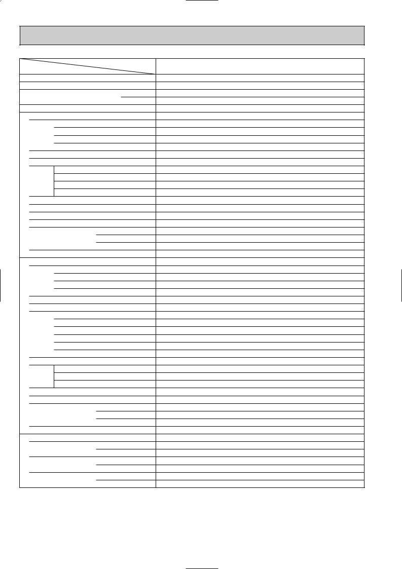
1. STANDARD SPECIFICATION
Service Ref.
Item
|
|
Indoor, Outdoor D.B./W.B.°C |
||||
Condition |
|
|
|
|
|
|
Capacity w1 |
|
|
|
Btu/h |
||
|
|
|
W |
|||
|
|
|
|
|
|
|
Total input |
w1 |
|
|
|
kW |
|
|
Service Ref. |
|
|
|
|
|
|
Power supply(phase, cycle, voltage) |
|
|
|||
|
|
Input |
|
|
|
kW |
|
|
Running current (Power factor) |
|
A(%) |
||
|
|
Starting current |
|
A |
||
|
External finish |
|
|
|
|
|
UNIT |
Heat exchanger |
|
|
|
|
|
Fan |
Fan(drive) o No. |
|
|
|||
|
|
|
||||
INDOOR |
|
Fan motor output |
|
kW |
||
Booster heater |
|
|
|
kW |
||
|
|
Airflow (Low-High) |
|
m3/min(CFM) |
||
|
|
External static pressure |
|
Pa(mmAq) |
||
|
Operation control & Thermostat |
|
|
|||
|
|
|
||||
|
Noise level (Low-High) |
w2 |
|
dB |
||
|
Unit drain pipe. O.D. |
|
|
|
mm(in.) |
|
|
|
|
|
W |
|
mm(in.) |
|
Dimensions |
|
D |
|
mm(in.) |
|
|
|
|
|
H |
|
mm(in.) |
|
Weight |
|
|
|
|
kg(lbs) |
|
Service Ref. |
|
|
|
|
|
|
Power supply (phase, cycle, voltage) |
|
|
|||
|
|
Input |
|
|
|
kW |
|
|
Running current |
(Power factor) |
|
A(%) |
|
|
|
Starting current |
|
A |
||
|
External finish |
|
|
|
|
|
|
Refrigerant control |
|
|
|
|
|
|
Compressor |
|
|
|
|
|
|
|
Model |
|
|
|
|
UNIT |
|
Motor output |
|
|
|
kW |
Fan |
Starter type |
|
|
|
|
|
OUTDOOR |
Fan(drive) o No. |
|
|
|||
|
|
Protection devices |
|
|
||
|
|
Crankcase heater |
|
|
||
|
Heat exchanger |
|
|
|
W |
|
|
|
Fan motor output |
|
kW |
||
|
|
|
||||
|
|
Airflow |
|
|
|
m3/min(CFM) |
|
Defrost method |
|
|
|
|
|
|
Noise level w2 |
|
|
|
dB(A) |
|
|
|
|
|
W |
|
mm(in.) |
|
Dimensions |
|
D |
|
mm(in.) |
|
|
|
|
|
H |
|
mm(in.) |
|
Weight |
|
|
|
|
kg(lbs) |
PIPING |
Refrigerant Charge |
|
|
|
kg(lbs) |
|
Pipe size O.D. |
|
Liquid |
|
mm(in.) |
||
|
|
|
|
|
||
REFRIGERANT |
|
|
|
Gas |
|
mm(in.) |
Connection method |
|
Indoor side |
||||
|
|
|||||
|
|
Outdoor side |
||||
|
|
|
|
|||
|
Between the indoor & |
|
Height difference |
|||
|
outdoor units |
|
Piping length |
|||
|
|
|
|
|
|
|
PK-2.5FLD PK-2.5FLD1 PK-2.5FLD2
27/19.0°C, 35/24°C |
|
w4 |
|
Cooling (JIS B8616) |
|
w5 |
|
23,900 |
|
24,400 |
22,700 |
7,000 |
|
7,150 |
6,650 |
2.56 / 2.62 |
|
3.01 |
3.54 |
PK-2.5FLD PK-2.5FLD1 PK-2.5FLD2 |
|
||
Single, 50Hz, 220/240V |
|
Single, 60Hz, 220V |
|
0.095 / 0.095 |
|
0.095 |
|
0.44 / 0.44 (98/90) |
|
0.44 (98) |
|
0.7 / 0.8 |
|
0.7 |
|
Munsell 3.4Y 7.7/0.8(White) |
|
||
Plate fin coil |
|
|
|
Line flow (direct) o 2 |
|
|
|
0.04 |
|
|
|
15 - 20(530-706) |
|
|
|
0 (direct blow) |
|
|
|
— |
|
|
|
Wireless remote controller & Built-in |
|
||
39 - 45 |
|
|
|
20 (13/16) |
|
|
|
1,400 (55-1/8) |
|
|
|
235 (9-1/4) |
|
|
|
340 (13-3/8) |
|
|
|
24 (53) |
|
|
|
PU-2.5VJA2 |
|
PU-2.5NJA1 |
|
Single, 50Hz, 220/240V |
|
Single, 60Hz, 220V |
|
2.46 / 2.52 |
|
2.91 |
3.44 |
11.4 / 10.7 (98/98) |
|
13.4 (99) |
15.8(99) |
45 / 49 |
|
58 |
58 |
Munsell 5Y 7/1 |
|
|
|
Capillary tube |
|
|
|
Hermetic |
|
|
|
|
|
|
|
NHJ41VMD |
|
NHJ38NBD |
|
2.0 |
|
1.7 |
|
Line start |
|
|
|
Inner thermostat, HP/LP switch |
|
||
32 / 38 |
|
— |
|
Plate fin coil |
|
|
|
Propeller (direct) o 1 |
|
|
|
0.085 |
|
|
|
50 (1765) |
|
|
|
— |
|
|
|
52 |
|
53 |
|
870 (34-1/4) |
|
|
|
295 (+24) (11-5/8 (add 1)) |
|
|
|
850 (33-7/16) |
|
|
|
71 (157) |
|
|
|
|
|
|
|
R-22 2.4 (5.3) |
|
R-22 2.4 (5.3) |
|
9.52 (3/8) |
|
|
|
15.88 (5/8) |
|
|
|
Flared |
|
|
|
Flared |
|
|
|
w3 Max. 20m |
|
|
|
w3 Max. 30m |
|
|
|
w1 Refrigerant piping length (one way) : 5m (16ft)
w2 Noise level is measured in an unacoustic room based on JIS conditions. w3 Up to 20m it is unnecessary to charge additional refrigerant.
w4 Indoor, Outdoor D.B./W.B. : 29/19°C, 46/24°C. w5 Cooling SSA385, 386
5
Service Ref.
Item
|
|
Indoor, Outdoor D.B./W.B.°C |
||||
Condition |
|
|
|
|
|
|
Capacity w1 |
|
|
|
Btu/h |
||
|
|
|
W |
|||
|
|
|
|
|
|
|
Total input |
w1 |
|
|
|
kW |
|
|
Service Ref. |
|
|
|
|
|
|
Power supply(phase, cycle, voltage) |
|
|
|||
|
|
Input |
|
|
|
kW |
|
|
Running current (Power factor) |
|
A(%) |
||
|
|
Starting current |
|
A |
||
|
External finish |
|
|
|
|
|
UNIT |
Heat exchanger |
|
|
|
|
|
Fan |
Fan(drive) o No. |
|
|
|||
|
|
|
||||
INDOOR |
|
Fan motor output |
|
kW |
||
Booster heater |
|
|
|
kW |
||
|
|
Airflow (Low-High) |
|
m3/min(CFM) |
||
|
|
External static pressure |
|
Pa(mmAq) |
||
|
Operation control & Thermostat |
|
|
|||
|
|
|
||||
|
Noise level (Low-High) |
w2 |
|
dB |
||
|
Unit drain pipe. O.D. |
|
|
|
mm(in.) |
|
|
|
|
|
W |
|
mm(in.) |
|
Dimensions |
|
D |
|
mm(in.) |
|
|
|
|
|
H |
|
mm(in.) |
|
Weight |
|
|
|
|
kg(lbs) |
|
Service Ref. |
|
|
|
|
|
|
Power supply (phase, cycle, voltage) |
|
|
|||
|
|
Input |
|
|
|
kW |
|
|
Running current |
(Power factor) |
|
A(%) |
|
|
|
Starting current |
|
A |
||
|
External finish |
|
|
|
|
|
|
Refrigerant control |
|
|
|
|
|
|
Compressor |
|
|
|
|
|
UNIT |
|
Model |
|
|
|
|
|
Motor output |
|
|
|
kW |
|
OUTDOOR |
Heat exchanger |
|
|
|
|
|
|
|
Starter type |
|
|
|
|
|
|
Protection devices |
|
|
||
|
|
Crankcase heater |
|
W |
||
|
Fan |
Fan(drive) o No. |
|
|
||
|
|
Fan motor output |
|
kW |
||
|
|
|
||||
|
|
Airflow |
|
|
|
m3/min(CFM) |
|
Defrost method |
|
|
|
|
|
|
Noise level w2 |
|
|
|
dB |
|
|
|
|
|
W |
|
mm(in.) |
|
Dimensions |
|
D |
|
mm(in.) |
|
|
|
|
|
H |
|
mm(in.) |
PIPING |
Weight |
|
|
|
|
kg(lbs) |
Refrigerant Charge |
|
|
|
kg(lbs) |
||
|
|
|
|
|||
|
Pipe size O.D. |
|
Liquid |
|
mm(in.) |
|
|
|
|
||||
REFRIGERANT |
|
Gas |
|
mm(in.) |
||
|
|
|
|
|||
outdoor units |
|
Piping length |
||||
|
Connection method |
|
Indoor side |
|||
|
|
|
|
Outdoor side |
||
|
Between the indoor & |
|
Height difference |
|||
|
|
|
|
|
|
|
PK-3FLD PK-3FLD1 PK-3FLD2
|
|
27/19.0°C, 35/24°C |
|
w4 |
|
|
|
Cooling (JIS B8616) |
|
w5 |
|
27,000 |
|
28,400 |
23,500 |
||
7,900 |
|
8,200 |
6,900 |
||
3.28 / 3.30 |
|
3.28 / 3.30 |
|
3.54 |
4.19 |
|
|
PK-3FLD PK-3FLD1 PK-3FLD2 |
|
||
Single, 50Hz, 220/240V |
|
Single, 60Hz, 220V |
|
||
0.095 / 0.095 |
|
0.095 |
|
||
0.44 / 0.44 (98/90) |
|
0.44 (98) |
|
||
0.7 / 0.8 |
|
0.7 |
|
||
|
|
Munsell 3.4Y 7.7/0.8(White) |
|
||
|
|
Plate fin coil |
|
|
|
|
|
Line flow (direct) o 2 |
|
|
|
|
0.04 |
|
|
||
|
15 - 20 (530-706) |
|
|
||
|
|
0 (direct blow) |
|
|
|
|
|
— |
|
|
|
|
|
Wireless remote controller & Built-in |
|
||
|
39 - 45 |
|
|
||
|
20 (13/16) |
|
|
||
|
1,400 (55-1/8) |
|
|
||
|
235 (9-1/4) |
|
|
||
|
340 (13-3/8) |
|
|
||
|
24 (53) |
|
|
||
PU-3VJC |
|
PU-3YJC |
|
PU-3NJA1 |
|
Single, 50Hz, 220/240V |
|
3, 50Hz, 380/415V |
|
Single, 60Hz, 220V |
|
3.18 / 3.20 |
|
3.18 / 3.20 |
|
3.44 |
4.09 |
15.1/13.9(96/96) |
|
5.7/5.3(85/84) |
|
17.6(89) |
20.9(89) |
54 / 58 |
|
34 / 37 |
|
80 |
80 |
|
|
Munsell 5Y 7/1 |
|
|
|
|
|
Capillary tube |
|
|
|
|
|
Hermetic |
|
|
|
|
|
|
NHJ47NAD |
|
|
NH52VND |
|
NH52YDE |
|
|
|
2.2 |
|
2.4 |
|
2.2 |
|
|
|
Line start |
|
|
|
w6 |
|
w7 |
|
w6 |
|
32 / 38 |
|
32 / 38 |
|
38 |
|
|
|
Plate fin coil |
|
|
|
|
|
Propeller (direct) o 1 |
|
|
|
|
0.085 |
|
|
||
|
50 (1765) |
|
|
||
|
|
— |
|
|
|
|
52 |
|
53 |
|
|
|
|
|
|||
|
870 (34-1/4) |
|
|
||
|
|
295 (+24) (11-5/8 (add 1)) |
|
|
|
|
850 (33-7/16) |
|
|
||
|
73 (161) |
|
|
||
R-22 2.8 (6.2) |
|
R-22 3.5 (7.7) |
|
||
|
9.52 (3/8) |
|
|
||
|
15.88 (5/8) |
|
|
||
Flared
Flared
w3 Max. 20m
w3 Max. 30m
w1 Refrigerant piping length (one way) : 5m (16ft)
w2 Noise level is measured in an unacoustic room based on JIS conditions. w3 Up to 20m it is unnecessary to charge additional refrigerant.
w4 Indoor, Outdoor D.B./W.B. : 29/19°C, 46/24°C w5 Cooling SSA385, 386
w6 Inner thermostat, HP switch, LP switch.
w7 Thermal switch, Reversed-phase protector, HP switch, LP switch, Thermal relay.
6

Service Ref.
Item
|
|
Indoor, Outdoor D.B./W.B.°C |
||||
Condition |
|
|
|
|
|
|
Capacity w1 |
|
|
|
Btu/h |
||
|
|
|
W |
|||
|
|
|
|
|
|
|
Total input |
w1 |
|
|
|
kW |
|
|
Service Ref. |
|
|
|
|
|
|
Power supply(phase, cycle, voltage) |
|
|
|||
|
|
Input |
|
|
|
kW |
|
|
Running current (Power factor) |
|
A(%) |
||
|
|
Starting current |
|
A |
||
|
External finish |
|
|
|
|
|
UNIT |
Heat exchanger |
|
|
|
|
|
Fan |
Fan(drive) o No. |
|
|
|||
|
|
|
||||
INDOOR |
|
Fan motor output |
|
kW |
||
Booster heater |
|
|
|
kW |
||
|
|
Airflow (Low-High) |
|
m3/min(CFM) |
||
|
|
External static pressure |
|
Pa(mmAq) |
||
|
Operation control & Thermostat |
|
|
|||
|
|
|
||||
|
Noise level (Low-High) |
w2 |
|
dB |
||
|
Unit drain pipe. O.D. |
|
|
|
mm(in.) |
|
|
|
|
|
W |
|
mm(in.) |
|
Dimensions |
|
D |
|
mm(in.) |
|
|
|
|
|
H |
|
mm(in.) |
|
Weight |
|
|
|
|
kg(lbs) |
|
Service Ref. |
|
|
|
|
|
|
Power supply (phase, cycle, voltage) |
|
|
|||
|
|
Input |
|
|
|
kW |
|
|
Running current |
(Power factor) |
|
A(%) |
|
|
|
Starting current |
|
A |
||
|
External finish |
|
|
|
|
|
|
Refrigerant control |
|
|
|
|
|
|
Compressor |
|
|
|
|
|
UNIT |
|
Model |
|
|
|
|
|
Motor output |
|
|
|
kW |
|
OUTDOOR |
Heat exchanger |
|
|
|
|
|
|
|
Starter type |
|
|
|
|
|
|
Protection devices |
|
|
||
|
|
Crankcase heater |
|
W |
||
|
Fan |
Fan(drive) o No. |
|
|
||
|
|
Fan motor output |
|
kW |
||
|
|
Airflow |
|
|
|
m3/min(CFM) |
|
Defrost method |
|
|
|
|
|
|
Noise level w2 |
|
|
|
dB |
|
|
|
|
|
|||
|
|
|
|
W |
|
mm(in.) |
|
Dimensions |
|
D |
|
mm(in.) |
|
|
|
|
|
H |
|
mm(in.) |
PIPING |
Weight |
|
|
|
|
kg(lbs) |
Refrigerant Charge |
|
|
|
kg(lbs) |
||
|
|
|
|
|||
|
Pipe size O.D. |
|
Liquid |
|
mm(in.) |
|
REFRIGERANT |
|
Gas |
|
mm(in.) |
||
|
|
|
|
|||
outdoor units |
|
Piping length |
||||
|
Connection method |
|
Indoor side |
|||
|
|
|
|
Outdoor side |
||
|
Between the indoor & |
|
Height difference |
|||
|
|
|
|
|
|
|
PK-4FLSD PK-4FLSD1 PK-4FLSD2
|
27/19.0°C, 35/24°C |
|
w4 |
|
|
Cooling (JIS B8616) |
|
w5 |
|
35,200 |
|
39,000 |
33,800 |
|
10,300 |
|
11,400 |
9,900 |
|
3.46 / 3.63 |
3.40 / 3.47 |
|
4.38 |
5.08 |
|
PK-4FLSD PK-4FLSD1 PK-4FLSD2 |
|
||
Single, 50Hz, 220/240V |
|
Single, 60Hz, 220V |
|
|
0.114 / 0.114 |
|
0.114 |
|
|
0.53 / 0.53 (98/90) |
|
0.53 (98) |
|
|
0.8 / 0.9 |
|
0.8 |
|
|
|
Munsell 3.4Y 7.7/0.8(White) |
|
|
|
|
Plate fin coil |
|
|
|
|
Line flow (direct) o 2 |
|
|
|
|
0.07 |
|
|
|
|
22 - 28 (777 - 989) |
|
|
|
|
0 (direct blow) |
|
|
|
|
— |
|
|
|
|
Wireless remote controller & Built-in |
|
||
|
41 - 46 |
|
|
|
|
20 (13/16) |
|
|
|
|
1,680 (66-1/8) |
|
|
|
|
235 (9-1/4) |
|
|
|
|
340 (13-3/8) |
|
|
|
|
28 (62) |
|
|
|
PU-4VLJSA2 |
PU-4YJSA3 |
|
PU-4TJSA2 |
|
Single, 50Hz, 220/240V |
3, 50Hz, 380/415V |
|
3, 60Hz, 220V |
|
3.35 / 3.52 |
3.29 / 3.36 |
|
4.27 |
4.97 |
16.9 / 16.3 (90/90) |
5.7 / 5.5 (87/85) |
|
12.2 (92) |
14.0(93) |
79 / 79 |
38 / 38 |
|
69 |
69 |
|
Munsell 5Y 7/1 |
|
|
|
|
Capillary tube |
|
|
|
|
Hermetic |
|
|
|
|
|
|
|
|
NH56VND |
NHJ56YDE |
|
NHJ56TKA |
|
2.7 |
2.7 |
|
2.7 |
|
|
Line start |
|
|
|
|
|
|
|
|
w6 |
w7 |
|
w7 |
|
32 / 38 |
32 / 38 |
|
38 |
|
|
Plate fin coil |
|
|
|
|
Propeller (direct) o 2 |
|
|
|
|
0.065 + 0.065 |
|
|
|
|
95 (3352) |
|
|
|
|
— |
|
|
|
54 |
55 |
|
55 |
|
|
870 (34-1/4) |
|
|
|
|
295 (+24) (11-5/8 (add 1)) |
|
|
|
|
1258 (49-1/2) |
|
|
|
|
94 (207) |
|
|
|
R-22 3.8 (8.4) |
R-22 4.6 (10.1) |
|
R-22 4.6 (10.1) |
|
|
9.52 (3/8) |
|
|
|
|
19.05 (4/3) |
|
|
|
|
Flared |
|
|
|
|
Flared |
|
|
|
|
w3 Max. 30m |
|
|
|
|
w3 Max. 40m |
|
|
|
w1 Refrigerant piping length (one way) : 5m (16ft)
w2 Noise level is measured in an unacoustic room based on JIS conditions. w3 Up to 20m it is unnecessary to charge additional refrigerant.
w4 Indoor, Outdoor D.B./W.B. : 29/19°C, 46/24°C w5 Cooling SSA385, 386
w6 Inner thermostat, HP switch, LP switch, Thermal switch
w7 Thermal switch, Reversed-phase protector, HP switch, LP switch, Thermal relay.
7

2. POWER SUPPLY & MODEL NAMES
|
|
|
Service Ref. (Outdoor unit) |
|
||
|
|
|
|
|
|
|
Power supply |
Service Ref. (Indoor unit) |
PK-2.5FLD |
PK-3FLD |
PK-4FLSD |
|
|
PK-2.5FLD1 |
PK-3FLD1 |
PK-4FLSD1 |
|
|||
|
|
|
|
|||
|
|
|
PK-2.5FLD2 |
PK-3FLD2 |
PK-4FLSD2 |
|
|
|
|
|
|
|
|
50Hz |
1ph. |
220,230,240V |
PU-2.5VJA2 |
PU-3VJC |
PU-4VLJSA2 |
|
|
|
|
|
|
|
|
3ph. |
380/220,400/230,415/240V |
— |
PU-3YJC |
PU-4YJSA3 |
|
|
|
|
|||||
|
|
|
|
|
|
|
60Hz |
1ph. |
220V |
PU-2.5NJA1 |
PU-3NJA1 |
— |
|
|
|
|
|
|
|
|
3ph. |
220V |
— |
— |
PU-4TJSA2 |
|
|
|
|
|||||
|
|
|
|
|
|
|
Notes : 1. Power supply key N …… 1ph, 220V, 60Hz |
Y … 3ph, 380/220, 400/230, |
|||||
|
|
V(L) … 1ph, 220, 230 240V, 50Hz |
|
415/240V, 50Hz, 4 wires |
||
T…… 3ph, 220V, 60Hz
2.Primary power supplies for all indoor units are single-phase.
3.ELECTRICAL SPECIFICATION
Rating conditions |
|
|
JIS B8615, 8616 |
Indoor : D.B. 27°C (80°F), W.B. 19°C(66°F) |
|||||||
|
|
Outdoor : D.B. 35°C (95°F) |
|||||||||
Series PK Indoor Unit (Single Phase) |
|
||||||||||
|
|
|
|
|
|
||||||
|
|
|
|
|
|
|
|
|
|
|
|
Power supply (1 Phase) |
|
|
V : 220V 50Hz |
|
V : 230V 50Hz |
|
|||||
|
|
|
|
|
|
|
|
|
|
||
|
|
|
PK-2.5FLD |
PK-3FLD |
PK-4FLSD |
PK-2.5FLD |
PK-3FLD |
PK-4FLSD |
|
||
Service Ref. |
|
|
PK-2.5FLD1 |
PK-3FLD1 |
PK-4FLSD1 |
PK-2.5FLD1 |
PK-3FLD1 |
PK-4FLSD1 |
|
||
|
|
|
PK-2.5FLD2 |
PK-3FLD2 |
PK-4FLSD2 |
PK-2.5FLD2 |
PK-3FLD2 |
PK-4FLSD2 |
|
||
|
|
|
|
|
|
|
|
|
|
||
Current |
A |
|
0.44 |
0.44 |
0.53 |
0.44 |
0.44 |
0.53 |
|
||
|
|
|
|
|
|
|
|
|
|
||
Input |
kW |
|
0.095 |
0.095 |
0.114 |
0.095 |
0.095 |
0.114 |
|
||
|
|
|
|
|
|
|
|
|
|
|
|
Starting current |
A |
|
0.7 |
0.7 |
|
0.8 |
0.8 |
0.8 |
0.8 |
|
|
|
|
|
|
|
|
|
|
|
|
||
Outdoor unit |
|
|
PU-2.5 |
PU-3 |
PU-4 |
PU-2.5 |
PU-3 |
PU-4 |
|
||
|
|
|
|
|
|
|
|
|
|
|
|
|
|
|
|
|
|
|
|||||
Power supply (1 Phase) |
|
|
V : 240V 50Hz |
|
N : 220V 60Hz |
|
|||||
|
|
|
|
|
|
|
|
|
|
||
|
|
|
PK-2.5FLD |
PK-3FLD |
PK-4FLSD |
PK-2.5FLD |
PK-3FLD |
PK-4FLSD |
|
||
Service Ref. |
|
|
PK-2.5FLD1 |
PK-3FLD1 |
PK-4FLSD1 |
PK-2.5FLD1 |
PK-3FLD1 |
PK-4FLSD1 |
|
||
|
|
|
PK-2.5FLD2 |
PK-3FLD2 |
PK-4FLSD2 |
PK-2.5FLD2 |
PK-3FLD2 |
PK-4FLSD2 |
|
||
|
|
|
|
|
|
|
|
|
|
||
Current |
A |
|
0.44 |
0.44 |
0.53 |
0.44 |
0.44 |
0.53 |
|
||
|
|
|
|
|
|
|
|
|
|
||
Input |
kW |
|
0.095 |
0.095 |
0.114 |
0.095 |
0.095 |
0.114 |
|
||
|
|
|
|
|
|
|
|
|
|
|
|
Starting current |
A |
|
0.8 |
0.8 |
|
0.9 |
0.7 |
0.7 |
0.8 |
|
|
|
|
|
|
|
|
|
|
|
|
||
Outdoor unit |
|
|
PU-2.5 |
PU-3 |
PU-4 |
PU-2.5 |
PU-3 |
PU-4 |
|
||
|
|
|
|
|
|
|
|
|
|
|
|
8

5 
 DATA
DATA
1. PERFORMANCE DATA
COOLING CAPACITY 50Hz
ServiceRef. |
|
|
|
PK-2.5FLD |
PK-3FLD |
PK-4FLSD |
||||||
|
|
|
PK-2.5FLD1 |
PK-3FLD1 |
PK-4FLSD1 |
|||||||
|
|
|
|
PK-2.5FLD2 |
PK-3FLD2 |
PK-4.5FLSD2 |
||||||
Temperature |
|
|
|
T.C. |
|
C.F. |
T.C. |
|
C.F. |
T.C. |
|
C.F. |
OutdoorD.B. |
IndoorW.B. |
|
|
|
(T.I.) |
|
|
(T.I.) |
|
|
(T.I.) |
|
|
16: |
(60.8°F) |
7.0 |
|
0.81 |
7.9 |
|
0.81 |
10.4 |
|
0.81 |
|
21: |
18: |
(64.4°F) |
7.5 |
|
0.82 |
8.4 |
|
0.82 |
11.0 |
|
0.82 |
|
19: |
(66.2°F) |
7.7 |
|
0.83 |
8.7 |
|
0.83 |
11.3 |
|
0.83 |
||
(69.8°F) |
19.4: |
(67 |
°F) |
7.8 |
|
0.83 |
8.8 |
|
0.83 |
11.5 |
|
0.83 |
|
20: |
(68 |
°F) |
7.9 |
|
0.84 |
9.0 |
|
0.84 |
11.7 |
|
0.84 |
|
22: |
(71.6°F) |
8.4 |
|
0.86 |
9.5 |
|
0.86 |
12.4 |
|
0.86 |
|
|
16: |
(60.8°F) |
6.9 |
|
0.84 |
7.7 |
|
0.84 |
10.1 |
|
0.84 |
|
25: |
18: |
(64.4°F) |
7.3 |
|
0.85 |
8.3 |
|
0.85 |
10.8 |
|
0.85 |
|
19: |
(66.2°F) |
7.6 |
|
0.86 |
8.5 |
|
0.86 |
11.1 |
|
0.86 |
||
(77 °F) |
19.4: |
(67 |
°F) |
7.7 |
|
0.86 |
8.7 |
|
0.86 |
11.3 |
|
0.86 |
|
20: |
(68 |
°F) |
7.8 |
|
0.87 |
8.8 |
|
0.87 |
11.5 |
|
0.87 |
|
22: |
(71.6°F) |
8.3 |
|
0.89 |
9.4 |
|
0.89 |
12.2 |
|
0.89 |
|
|
16: |
(60.8°F) |
6.6 |
|
0.90 |
7.5 |
|
0.90 |
9.7 |
|
0.90 |
|
30: |
18: |
(64.4°F) |
7.1 |
|
0.92 |
8.0 |
|
0.92 |
10.4 |
|
0.92 |
|
19: |
(66.2°F) |
7.3 |
|
0.93 |
8.2 |
|
0.93 |
10.7 |
|
0.93 |
||
(86 °F) |
19.4: |
(67 |
°F) |
7.4 |
|
0.93 |
8.4 |
|
0.93 |
10.9 |
|
0.93 |
|
20: |
(68 |
°F) |
7.5 |
|
0.94 |
8.5 |
|
0.94 |
11.1 |
|
0.94 |
|
22: |
(71.6°F) |
8.0 |
|
0.96 |
9.0 |
|
0.96 |
11.8 |
|
0.96 |
|
|
16: |
(60.8°F) |
6.5 |
|
0.93 |
7.3 |
|
0.93 |
9.6 |
|
0.93 |
|
32.2: |
18: |
(64.4°F) |
6.9 |
|
0.95 |
7.8 |
|
0.95 |
10.1 |
|
0.95 |
|
19: |
(66.2°F) |
7.1 |
|
0.96 |
8.1 |
|
0.96 |
10.5 |
|
0.96 |
||
(90 °F) |
19.4: |
(67 |
°F) |
7.2 |
|
0.97 |
8.2 |
|
0.97 |
10.7 |
|
0.97 |
|
20: |
(68 |
°F) |
7.4 |
|
0.97 |
8.3 |
|
0.97 |
10.9 |
|
0.97 |
|
22: |
(71.6°F) |
7.8 |
|
0.99 |
8.8 |
|
0.99 |
11.5 |
|
0.99 |
|
|
16: |
(60.8°F) |
6.3 |
|
0.96 |
7.2 |
|
0.96 |
9.3 |
|
0.96 |
|
35: |
18: |
(64.4°F) |
6.8 |
|
0.99 |
7.6 |
|
0.99 |
10.0 |
|
0.99 |
|
19: |
(66.2°F) |
7.0 |
|
1.00 |
7.9 |
|
1.00 |
10.3 |
|
1.00 |
||
(95 °F) |
19.4: |
(67 |
°F) |
7.1 |
|
1.00 |
8.0 |
|
1.00 |
10.5 |
|
1.00 |
|
20: |
(68 |
°F) |
7.2 |
|
1.01 |
8.2 |
|
1.01 |
10.6 |
|
1.01 |
|
22: |
(71.6°F) |
7.7 |
|
1.04 |
8.7 |
|
1.04 |
11.3 |
|
1.04 |
|
|
16: |
(60.8°F) |
6.1 |
|
10.3 |
6.8 |
|
1.03 |
8.9 |
|
1.03 |
|
40: |
18: |
(64.4°F) |
6.5 |
|
1.06 |
7.3 |
|
1.06 |
9.5 |
|
1.06 |
|
19: |
(66.2°F) |
6.7 |
|
1.07 |
7.6 |
|
1.07 |
9.9 |
|
1.07 |
||
(104 °F) |
19.4: |
(67 |
°F) |
6.8 |
|
1.08 |
7.7 |
|
1.08 |
10.0 |
|
1.08 |
|
20: |
(68 |
°F) |
6.9 |
|
1.08 |
7.8 |
|
1.08 |
10.2 |
|
1.08 |
|
22: |
(71.6°F) |
7.4 |
|
1.11 |
8.3 |
|
1.11 |
10.9 |
|
1.11 |
|
|
16: |
(60.8°F) |
6.0 |
|
1.04 |
6.8 |
|
1.04 |
8.9 |
|
1.04 |
|
40.6: |
18: |
(64.4°F) |
6.4 |
|
1.06 |
7.3 |
|
1.06 |
9.5 |
|
1.06 |
|
19: |
(66.2°F) |
6.7 |
|
1.08 |
7.5 |
|
1.08 |
9.8 |
|
1.08 |
||
(105 °F) |
19.4: |
(67 |
°F) |
6.8 |
|
1.08 |
7.6 |
|
1.08 |
9.9 |
|
1.08 |
|
20: |
(68 °F) |
6.9 |
|
1.09 |
7.8 |
|
1.09 |
10.1 |
|
1.09 |
|
|
22: |
(71.6 |
°F) |
7.4 |
|
1.12 |
8.3 |
|
1.12 |
10.8 |
|
1.12 |
|
16: |
(60.8 |
°F) |
5.8 |
|
1.10 |
6.5 |
|
1.10 |
8.5 |
|
1.10 |
45: |
18: |
(64.4 |
°F) |
6.2 |
|
1.12 |
7.0 |
|
1.12 |
9.1 |
|
1.12 |
19: |
(66.2 |
°F) |
6.4 |
|
1.14 |
7.2 |
|
1.14 |
9.4 |
|
1.14 |
|
(113 °F) |
19.4: |
(67 |
°F) |
6.5 |
|
1.15 |
7.3 |
|
1.15 |
9.5 |
|
1.15 |
|
20: |
(68 |
°F) |
6.6 |
|
1.16 |
7.5 |
|
1.16 |
9.7 |
|
1.16 |
|
22: |
(71.6 |
°F) |
7.1 |
|
1.20 |
8.0 |
|
1.20 |
10.4 |
|
1.20 |
|
16: |
(60.8 |
°F) |
5.7 |
|
1.11 |
6.4 |
|
1.11 |
8.4 |
|
1.11 |
46: |
18: |
(64.4 |
°F) |
6.1 |
|
1.14 |
6.9 |
|
1.14 |
9.0 |
|
1.14 |
19: |
(66.2 |
°F) |
6.4 |
|
1.15 |
7.2 |
|
1.15 |
9.4 |
|
1.15 |
|
(115 °F) |
19.4: |
(67 |
°F) |
6.4 |
|
1.16 |
7.2 |
|
1.16 |
9.4 |
|
1.16 |
|
20: |
(68 |
°F) |
6.5 |
|
1.17 |
7.4 |
|
1.17 |
9.6 |
|
1.17 |
|
22: |
(71.6 |
°F) |
7.0 |
|
1.21 |
7.9 |
|
1.21 |
10.3 |
|
1.21 |
|
16: |
(60.8 |
°F) |
5.4 |
|
1.16 |
6.1 |
|
1.16 |
8.0 |
|
1.16 |
50: |
18: |
(64.4 |
°F) |
5.9 |
|
1.19 |
6.6 |
|
1.19 |
8.6 |
|
1.19 |
19: |
(66.2 |
°F) |
6.1 |
|
1.21 |
6.8 |
|
1.21 |
8.9 |
|
1.21 |
|
(69.8 °F) |
19.4: |
(67 |
°F) |
6.2 |
|
1.22 |
6.9 |
|
1.22 |
9.1 |
|
1.22 |
|
20: |
(68 |
°F) |
6.2 |
|
1.23 |
7.0 |
|
1.23 |
9.2 |
|
1.23 |
|
22: |
(71.6 |
°F) |
6.8 |
|
1.28 |
7.6 |
|
1.28 |
9.9 |
|
1.28 |
|
16: |
(60.8 |
°F) |
5.3 |
|
1.19 |
6.0 |
|
1.19 |
7.8 |
|
1.19 |
52: |
18: |
(64.4 |
°F) |
5.7 |
|
1.22 |
6.5 |
|
1.22 |
8.4 |
|
1.22 |
19: |
(66.2 |
°F) |
5.9 |
|
1.24 |
6.7 |
|
1.24 |
8.7 |
|
1.24 |
|
(125.5 °F) |
19.4: |
(67 |
°F) |
6.0 |
|
1.25 |
6.8 |
|
1.25 |
8.9 |
|
1.25 |
|
20: |
(68 |
°F) |
6.2 |
|
1.26 |
7.0 |
|
1.26 |
9.1 |
|
1.26 |
|
22: |
(71.6 |
°F) |
6.6 |
|
1.31 |
7.5 |
|
1.31 |
9.7 |
|
1.31 |
Evaporator airflow (CMM) |
|
|
|
20 |
|
20 |
|
28 |
||||
Bypassfactors |
|
|
|
|
0.11 |
|
0.12 |
|
0.12 |
|||
S.H.F. at rating conditions |
|
|
|
0.81 |
|
0.73 |
|
0.75 |
||||
Notes: 1. T.C.: Total capacity (kW) … (kcal/h)=(kW)x860, (Btu/h)=4x(kW)x860
C.F.(T.I.) : Correction factors of Total input(Indoor unit input + Outdoor unit input)
2. (°F)=32+9/5(°C)
3. Guaranteed operating range(cooling) { Lower limit … Indoor : D.B. 21°C(70°F), W.B. 15.5°C(60°F), Outdoor : D.B. 21°C(70°F).
Upper limit … Indoor : D.B. 35°C(95°F), W.B. 22.5°C(72.5°F), Outdoor : D.B. 452°C(125.5°F).
9

COOLING CAPACITY 60Hz
|
|
|
|
PK-2.5FLD |
|
PK-3FLD |
PK-4FLSD |
|||||
ServiceRef. |
|
|
|
PK-2.5FLD1 |
|
PK-3FLD1 |
PK-4FLSD1 |
|||||
|
|
|
|
PK-2.5FLD2 |
|
PK-3FLD2 |
PK-4FLSD2 |
|||||
Temperature |
|
|
|
T.C. |
|
C.F. |
T.C. |
|
C.F. |
T.C. |
|
C.F. |
OutdoorD.B. |
IndoorW.B. |
|
|
|
(T.I.) |
|
|
(T.I.) |
|
|
(T.I.) |
|
|
16: |
(60.8°F) |
7.2 |
|
0.81 |
8.2 |
|
0.81 |
11.5 |
|
0.81 |
|
21: |
18: |
(64.4°F) |
7.6 |
|
0.82 |
8.7 |
|
0.82 |
12.1 |
|
0.82 |
|
19: |
(66.2°F) |
7.9 |
|
0.83 |
9.0 |
|
0.83 |
12.5 |
|
0.83 |
||
(69.8°F) |
19.4: |
(67 |
°F) |
8.0 |
|
0.83 |
9.1 |
|
0.83 |
12.7 |
|
0.83 |
|
20: |
(68 |
°F) |
8.1 |
|
0.84 |
9.3 |
|
0.84 |
12.9 |
|
0.84 |
|
22: |
(71.6°F) |
8.6 |
|
0.86 |
9.8 |
|
0.86 |
13.7 |
|
0.86 |
|
|
16: |
(60.8°F) |
7.0 |
|
0.84 |
8.0 |
|
0.84 |
11.2 |
|
0.84 |
|
25: |
18: |
(64.4°F) |
7.5 |
|
0.85 |
8.6 |
|
0.85 |
11.9 |
|
0.85 |
|
19: |
(66.2°F) |
7.7 |
|
0.86 |
8.9 |
|
0.86 |
12.3 |
|
0.86 |
||
(77°F) |
19.4: |
(67 |
°F) |
7.8 |
|
0.86 |
9.0 |
|
0.86 |
12.5 |
|
0.86 |
|
20: |
(68 |
°F) |
8.0 |
|
0.87 |
9.1 |
|
0.87 |
12.7 |
|
0.87 |
|
22: |
(71.6°F) |
8.5 |
|
0.89 |
9.7 |
|
0.89 |
13.5 |
|
0.89 |
|
|
16: |
(60.8°F) |
6.8 |
|
0.90 |
7.7 |
|
0.90 |
10.8 |
|
0.90 |
|
30: |
18: |
(64.4°F) |
7.2 |
|
0.92 |
8.3 |
|
0.92 |
11.5 |
|
0.92 |
|
19: |
(66.2°F) |
7.4 |
|
0.93 |
8.5 |
|
0.93 |
11.9 |
|
0.93 |
||
(86°F) |
19.4: |
(67 |
°F) |
7.6 |
|
0.93 |
8.7 |
|
0.93 |
12.1 |
|
0.93 |
|
20: |
(68 |
°F) |
7.7 |
|
0.94 |
8.8 |
|
0.94 |
12.2 |
|
0.94 |
|
22: |
(71.6°F) |
8.2 |
|
0.96 |
9.4 |
|
0.96 |
13.0 |
|
0.96 |
|
|
16: |
(60.8°F) |
6.6 |
|
0.93 |
7.6 |
|
0.93 |
10.6 |
|
0.93 |
|
32.2: |
18: |
(64.4°F) |
7.0 |
|
0.95 |
8.1 |
|
0.95 |
11.2 |
|
0.95 |
|
19: |
(66.2°F) |
7.3 |
|
0.96 |
8.4 |
|
0.96 |
11.6 |
|
0.96 |
||
(90°F) |
19.4: |
(67 |
°F) |
7.4 |
|
0.97 |
8.5 |
|
0.97 |
11.8 |
|
0.97 |
|
20: |
(68 |
°F) |
7.5 |
|
0.97 |
8.7 |
|
0.97 |
12.0 |
|
0.97 |
|
22: |
(71.6°F) |
8.0 |
|
0.99 |
9.2 |
|
0.99 |
12.8 |
|
0.99 |
|
|
16: |
(60.8°F) |
6.5 |
|
0.96 |
7.4 |
|
0.96 |
10.3 |
|
0.96 |
|
35: |
18: |
(64.4°F) |
6.9 |
|
0.99 |
7.9 |
|
0.99 |
11.0 |
|
0.99 |
|
19: |
(66.2°F) |
7.2 |
|
1.00 |
8.2 |
|
1.00 |
11.4 |
|
1.00 |
||
(95°F) |
19.4: |
(67 |
°F) |
7.3 |
|
1.00 |
8.3 |
|
1.00 |
11.6 |
|
1.00 |
|
20: |
(68 |
°F) |
7.4 |
|
1.01 |
8.5 |
|
1.01 |
11.8 |
|
1.01 |
|
22: |
(71.6°F) |
7.9 |
|
1.04 |
9.0 |
|
1.04 |
12.5 |
|
1.04 |
|
|
16: |
(60.8°F) |
6.2 |
|
1.03 |
7.1 |
|
1.03 |
9.9 |
|
1.03 |
|
40: |
18: |
(64.4°F) |
6.6 |
|
1.06 |
7.6 |
|
1.06 |
10.6 |
|
1.06 |
|
19: |
(66.2°F) |
6.8 |
|
1.07 |
7.9 |
|
1.07 |
10.9 |
|
1.07 |
||
(104°F) |
19.4: |
(67 |
°F) |
7.0 |
|
1.08 |
8.0 |
|
1.08 |
11.1 |
|
1.08 |
|
20: |
(68 |
°F) |
7.1 |
|
1.08 |
8.1 |
|
1.08 |
11.3 |
|
1.08 |
|
22: |
(71.6°F) |
7.6 |
|
1.11 |
8.7 |
|
1.11 |
12.0 |
|
1.11 |
|
|
16: |
(60.8°F) |
6.1 |
|
1.04 |
7.1 |
|
1.04 |
9.8 |
|
1.04 |
|
40.6: |
18: |
(64.4°F) |
6.6 |
|
1.06 |
7.5 |
|
1.06 |
10.5 |
|
1.06 |
|
19: |
(66.2°F) |
6.8 |
|
1.08 |
7.8 |
|
1.08 |
10.8 |
|
1.08 |
||
(105 °F) |
19.4: |
(67 |
°F) |
6.9 |
|
1.08 |
7.9 |
|
1.08 |
11.0 |
|
1.08 |
|
20: |
(68 |
°F) |
7.0 |
|
1.09 |
8.1 |
|
1.09 |
11.2 |
|
1.09 |
|
22: |
(71.6°F) |
7.5 |
|
1.12 |
8.6 |
|
1.12 |
12.0 |
|
1.12 |
|
|
16: |
(60.8°F) |
5.9 |
|
1.10 |
6.8 |
|
1.10 |
9.4 |
|
1.10 |
|
45: |
18: |
(64.4°F) |
6.3 |
|
1.12 |
7.2 |
|
1.12 |
10.1 |
|
1.12 |
|
19: |
(66.2°F) |
6.5 |
|
1.14 |
7.5 |
|
1.14 |
10.4 |
|
1.14 |
||
(113 °F) |
19.4: |
(67 |
°F) |
6.6 |
|
1.15 |
7.6 |
|
1.15 |
10.5 |
|
1.15 |
|
20: |
(68 |
°F) |
6.7 |
|
1.16 |
7.7 |
|
1.16 |
10.8 |
|
1.16 |
|
22: |
(71.6°F) |
7.2 |
|
1.20 |
8.3 |
|
1.20 |
11.5 |
|
1.20 |
|
|
16: |
(60.8°F) |
5.8 |
|
1.11 |
6.7 |
|
1.11 |
9.3 |
|
1.11 |
|
46: |
18: |
(64.4°F) |
6.2 |
|
1.14 |
7.1 |
|
1.14 |
9.9 |
|
1.14 |
|
19: |
(66.2°F) |
6.5 |
|
1.15 |
7.5 |
|
1.15 |
10.4 |
|
1.15 |
||
(115 °F) |
19.4: |
(67 |
°F) |
6.6 |
|
1.16 |
7.5 |
|
1.16 |
10.5 |
|
1.16 |
|
20: |
(68 |
°F) |
6.7 |
|
1.17 |
7.7 |
|
1.17 |
10.7 |
|
1.17 |
|
22: |
(71.6°F) |
7.2 |
|
1.21 |
8.2 |
|
1.21 |
11.4 |
|
1.21 |
|
|
16: |
(60.8°F) |
5.6 |
|
1.16 |
6.4 |
|
1.16 |
8.9 |
|
1.16 |
|
50: |
18: |
(64.4°F) |
6.0 |
|
1.19 |
6.9 |
|
1.19 |
9.5 |
|
1.19 |
|
19: |
(66.2°F) |
6.2 |
|
1.21 |
7.1 |
|
1.21 |
9.9 |
|
1.21 |
||
(69.8 °F) |
19.4: |
(67 |
°F) |
6.3 |
|
1.22 |
7.2 |
|
1.22 |
10.0 |
|
1.22 |
|
20: |
(68 |
°F) |
6.4 |
|
1.23 |
7.3 |
|
1.23 |
10.1 |
|
1.23 |
|
22: |
(71.6°F) |
6.9 |
|
1.28 |
7.9 |
|
1.28 |
11.0 |
|
1.28 |
|
|
16: |
(60.8°F) |
5.4 |
|
1.19 |
6.2 |
|
1.19 |
8.7 |
|
1.19 |
|
52: |
18: |
(64.4°F) |
5.9 |
|
1.22 |
6.7 |
|
1.22 |
9.3 |
|
1.22 |
|
19: |
(66.2°F) |
6.0 |
|
1.24 |
6.9 |
|
1.24 |
9.6 |
|
1.24 |
||
(125.5°F) |
19.4: |
(67 |
°F) |
6.2 |
|
1.25 |
7.1 |
|
1.25 |
9.8 |
|
1.25 |
|
20: |
(68 |
°F) |
6.3 |
|
1.26 |
7.2 |
|
1.26 |
10.0 |
|
1.26 |
|
22: |
(71.6°F) |
6.8 |
|
1.31 |
7.7 |
|
1.31 |
10.8 |
|
1.31 |
|
Evaporator airflow (CMM) |
|
|
|
20 |
|
20 |
|
28 |
||||
Bypassfactors |
|
|
|
|
0.11 |
|
0.12 |
|
0.12 |
|||
S.H.F. at rating conditions |
|
|
|
0.78 |
|
0.72 |
|
0.72 |
||||
Notes: 1. T.C.: Total capacity (kW) … (kcal/h)=(kW)x860, (Btu/h)=4x(kW)x860
C.F.(T.I.) : Correction factors of Total input(Indoor unit input + Outdoor unit input)
2. (°F)=32+9/5(°C)
3. Guaranteed operating range(cooling){ Lower limit … Indoor : D.B. 21°C(70°F), W.B. 15.5°C(60°F), Outdoor : D.B. 21°C(70°F).
Upper limit … Indoor : D.B. 35°C(95°F), W.B. 22.5°C(72.5°F), Outdoor : D.B. 52°C(125.5°F)…NJ, TJ
10
COOLING CAPACITY correction factors 50Hz
Service Ref. |
|
|
Refrigerant piping length (one way) |
|
|
||||
5m (16ft) |
10m (33ft) |
15m (49ft) |
20m (66ft) |
25m (82ft) |
30m (98ft) |
35m (115ft) |
40m (13ft) |
||
|
|||||||||
PK-2.5FLD/1/2 |
1.0 |
0.983 |
0.972 |
0.961 |
0.951 |
0.940 |
— |
— |
|
PK-3FLD/1/2 |
1.0 |
0.978 |
0.962 |
0.948 |
0.934 |
0.921 |
— |
— |
|
PK-4FLSD/1/2 |
1.0 |
0.984 |
0.974 |
0.964 |
0.954 |
0.944 |
0.914 |
0.902 |
|
COOLING CAPACITY correction factors 60Hz
Service Ref. |
|
|
Refrigerant piping length (one way) |
|
|
||||
5m (16ft) |
10m (33ft) |
15m (49ft) |
20m (66ft) |
25m (82ft) |
30m (98ft) |
35m (115ft) |
40m (131ft) |
||
|
|||||||||
PK-2.5FLD/1/2 |
1.0 |
0.978 |
0.963 |
0.948 |
0.934 |
0.921 |
— |
— |
|
PK-3FLD/1/2 |
1.0 |
0.971 |
0.950 |
0.931 |
0.913 |
0.896 |
— |
— |
|
PK-4FLSD/1/2 |
1.0 |
0.980 |
0.966 |
0.952 |
0.939 |
0.926 |
0.941 |
0.902 |
|
2. STANDARD OPERATION DATA
Electrical Circuit Total
Outdoorside Indoor side Refrigerant circuit
Service Ref. |
|
PK-2.5FLD |
PK-3FLD |
PK-4FLSD |
|||||
|
PK-2.5FLD1 |
PK-3FLD1 |
PK-4FLSD1 |
||||||
|
|
|
PK-2.5FLD2 |
PK-3FLD2 |
PK-4FLSD2 |
||||
MODE |
|
COOLING |
COOLING |
COOLING |
COOLING |
COOLING |
COOLING |
||
Capacity |
W |
7,000 |
6,650 |
7,900 |
6,900 |
10,300 |
9,900 |
||
Input |
kw |
2.56 |
3.54 |
3.28 |
4.19 |
3.46 |
5.08 |
||
Indoor unit Service Ref. |
PK-2.5FLD |
PK-3FLD |
PK-4FLSD |
||||||
PK-2.5FLD1 |
PK-3FLD1 |
PK-4FLSD1 |
|||||||
|
|
|
PK-2.5FLD2 |
PK-3FLD2 |
PK-4FLSD2 |
||||
phase, Hz |
|
1,50 |
1,60 |
1,50 |
1,60 |
1,50 |
1,60 |
||
Volts |
|
220 |
220 |
220 |
220 |
220 |
220 |
||
Amperes |
|
0.44 |
0.44 |
0.44 |
0.44 |
0.53 |
0.53 |
||
Outdoor unit Service Ref. |
PU- |
PU- |
PU- |
PU- |
PU- |
PU- |
|||
2.5VJA2 |
2.5NJA1 |
3VJC |
3NJA1 |
4YJSA3 |
4TJSA2 |
||||
|
|
|
|||||||
|
|
|
|
|
|
|
|
|
|
phase, Hz |
|
1,50 |
1,60 |
1,50 |
1,60 |
3,50 |
3,60 |
||
Volts |
|
220 |
220 |
220 |
220 |
380 |
220 |
||
Amperes |
|
11.4 |
15.8 |
15.1 |
20.9 |
5.7 |
14.0 |
||
Discharge pressure |
Mpa |
2.05 |
2.13 |
1.99 |
2.07 |
1.80 |
1.93 |
||
(O/F) |
(20.9) |
(21.7) |
(20.3) |
(21.1) |
(18.4) |
(19.7) |
|||
|
|
||||||||
Suction pressure |
Mpa |
0.47 |
0.44 |
0.47 |
0.44 |
0.48 |
0.45 |
||
(O/F) |
(4.79) |
(4.49) |
(4.79) |
(4.49) |
(4.89) |
(4.59) |
|||
|
|
||||||||
Discharge temperature |
: |
74.3 |
87 |
86 |
70 |
65 |
74 |
||
Condensing temperature |
: |
52 |
54 |
51 |
53 |
49 |
52 |
||
Suction temp. |
: |
10.3 |
10 |
6 |
4 |
6 |
5 |
||
Ref. pipe length |
m |
5 |
5 |
5 |
5 |
5 |
5 |
||
Intake air temperature |
D.B. |
: |
27 |
29 |
27 |
29 |
27 |
29 |
|
W.B. |
: |
19 |
19 |
19 |
19 |
19 |
19 |
||
|
|||||||||
Discharge air temperature |
D.B. |
: |
14.4 |
14.1 |
13.0 |
13.2 |
13.6 |
13.2 |
|
Intake air temperature |
D.B. |
: |
35 |
46 |
35 |
46 |
35 |
46 |
|
W.B. |
: |
24 |
24 |
24 |
24 |
24 |
24 |
||
|
|||||||||
Total Electrical circuit Refrigerant circuit Indoor side Outdoor side
The unit of pressure has been changed to Mpa on the international system of unit(SI unit system). The converted score against the traditional unit system can be gotten according to the formula below. 1(Mpa)=10.2(O/F)
3. ADDITIONAL REFRIGERANT CHARGE (R-22… |
kg(lbs)) |
|
|
|
|||
Service Ref. |
Outdoor unit precharged (kg) |
|
|
Refrigerant piping length (one way) |
|
||
(up to 20m) |
20m (66ft) |
|
25m (82ft) |
30m (98ft) |
35m (115ft) |
40m (131ft) |
|
|
|
||||||
PK-2.5FLD/1/2 |
V---2.4, N---2.4 |
0 |
|
0.06(0.13) |
0.12(0.26) |
— |
— |
PK-3FLD/1/2 |
V---2.8, Y---2.8, N---3.5 |
0 |
|
0.06(0.13) |
0.12(0.26) |
— |
— |
PK-4FLSD/1/2 |
VL---3.8, Y---4.6, T---4.6 |
0 |
|
0.15(0.33) |
0.30(0.66) |
0.45(0.99) |
0.6(1.32) |
11
4. OUTLET AIR SPEED AND COVERAGE RANGE
60Hz 50Hz Frequency
Configuration |
|
|
Wall mounted |
|
Service Ref. |
|
PK-2.5FLD |
PK-3FLD |
PK-4FLSD |
|
PK-2.5FLD1 |
PK-3FLD1 |
PK-4FLSD1 |
|
|
|
PK-2.5FLD2 |
PK-3FLD2 |
PK-4FLSD2 |
Airflow |
m3/min |
20 |
20 |
28 |
Air speed |
m/sec. |
4.9 |
4.9 |
5.4 |
Coverage rangew |
m(ft) |
12.4(41) |
12.4(41) |
15.3(50) |
Airflow |
m3/min |
20 |
20 |
28 |
Air speed |
m/sec. |
4.9 |
4.9 |
5.4 |
Coverage rangew |
m(ft) |
12.4(41) |
12.4(41) |
15.3(50) |
|
|
|
|
|
wThe air coverage range is the value up to the position where the air speed is 0.25m/sec. when air is blown out horizontally from the unit at the Hi notch position.
The coverage range should be used only as a general guideline since it varies according to the size of the room and furniture inside the room.
6 
 OUTLINES AND DIMENSIONS
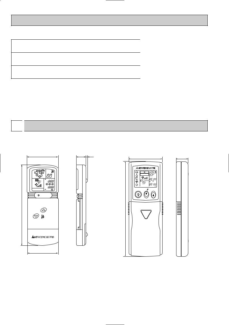
1. REMOTE CONTROLLER |
|
|
Unit : mm |
57 |
18 |
3 |
19 |
|
|
58 |
|
|
|
CHECK TESTRUN |
|
|
|
MODEL SELECT |
˚C |
˚C |
|
|
AMPM |
AM |
|
|
AMPM |
PM |
|
|
|
AM |
|
NOT AVAILABLE |
|
|
|
|
|
PM |
|
ON/OFF |
TEMP |
NOT AVAILABLE |
|
||
ON / OFF |
|
|
|
153 |
|
162 |
|
TEMP |
|
|
|
55
PK-2.5FLD PK-2.5FLD1 PK-3FLD PK-3FLD1 PK-4FLSD PK-4FLSD1
PK-2.5FLD2 PK-3FLD2 PK-4FLSD2
12

|
|
|
|
2. INDOOR UNIT |
|
Unit : mm |
|
PK-2.5FLD PK-3FLD |
|
|
|
PK-2.5FLD1 |
PK-3FLD1 |
|
|
PK-2.5FLD2 |
PK-3FLD2 |
Top |
|
|
|
||
|
|
62.5 |
|
A
235 |
45 |
235 |
45 |
235 |
45 |
235 |
13 |
|
|
|
|
Front |
|
|
Right side |
Left side |
1400 |
235 |
|
1090 Air intake |
|
340 |
|
197 |
Knock out hole for right piping
Refrigerant pipe. Drain pipe
C
Knock out hole for |
Liquid pipe |
Terminal block for control |
15 |
|
|
||
|
|
|
|
left piping |
|
|
|
Bolt
Terminal block for power supply Gas pipe
Drain hose for |
25 |
Drain hose |
|
||
left-hand side piping |
|
|
1110
|
42 |
58 |
|
55 (Gas pipe) |
|
183 |
120 |
|
|
|
(Liquid pipe) |
Drain hose
107
111
Lower side
Liquid pipe 9.52(3/8F)
Auto vane |
Gas pipe 15.88(5/8F) |
|
1120 |
|
240 |
552 Air outlet |
552 Air outlet |
|
100 |
39 |
|
4 |
|
Under panel |
|
|
|
|
|
|
|
|
|
|
Change vane (manual) |
||||||||||||
|
Removable at left-hand |
|
|
|
|
|
|
|
|
|
|
|
|
|
|
B |
||||||||
|
|
|
|
|
|
|
|
|
|
|
|
|
|
|
|
|||||||||
|
side piping |
|
|
|
Knock out hole for under-piping |
|||||||||||||||||||
|
|
|
|
|
|
|
|
|||||||||||||||||
|
|
|
|
|
|
|
|
Refrigerant pipe. Drain pipe |
||||||||||||||||
|
|
|
|
Knock out hole for piping |
|
|
|
|||||||||||||||||
|
|
|
|
|
|
|
|
|
|
|
|
|
|
|
|
|
|
|
||||||
A |
|
|
|
B |
|
|
|
|
|
|
|
|
|
C |
|
|
|
|||||||
30 |
|
|
|
|
|
|
|
|
|
|
|
|
|
30 |
|
|
|
|
||||||
|
|
|
|
|
|
|
|
|
|
|
|
|
|
|
|
|
|
|
|
|
|
|
|
|
|
|
|
|
|
|
|
|
|
|
|
|
|
|
|
|
|
|
|
|
|
|
100 |
|
|
|
|
|
|
|
|
|
|
|
|
|
|
|
|
|
|
|
|
|
|
|
|
|
|
|
|
|
|
|
|
|
|
|
|
|
|
|
|
|
65 |
|
|
|
|
|
|
|
|
|
|
|
|
|
|
|
|
|
|
|
|
|
|
|
|
|
|
|
|
|
|
|
|
|
||
|
|
|
|
|
|
|
|
|
|
|
|
|
|
|
|
|
|
|
|
|
|
|
|
|
|
|
|
|
|
|
|
|
|
|
|
|
|
|
|
|
|
|
39 |
|
|
|
|||
|
|
|
|
|
39 |
|
|
37 |
|
|
|
|
|
|
|
|
|
|
||||||
37 |
|
|
|
|
|
32 |
|
|
|
|
|
|
|
|
37 |
|
|
|
|
|||||
|
|
|
|
|
|
|
|
|
|
|
||||||||||||||
74 |
|
|
|
|
98 |
|
|
|
|
|
|
74 |
|
|
4 |
|
||||||||
|
|
|
|
|
|
|
|
|
|
|
|
|
|
|
|
|
|
|||||||
|
|
|
|
|
|
|
|
|
|
|
|
|
|
|
|
|
|
|
|
|
|
|
|
|
Unit center
|
|
|
990 |
|
|
245 |
|
|
|
|
|
|
10 |
91=(910) |
455 |
|
285 |
|
|
|
|
|
|
|
|
|
|
|
|
|||
|
|
|
900 |
|
|
19 |
|
|
|
|
Wall fixture |
18 |
18 Drainage range |
Drainage range |
91 |
|
10 |
30 |
29 |
|
|
|
|
on left-hand side |
on right-hand side |
|
|
|
||||
66-ø6 hole for |
|
|
|
|
|
|
184 |
30 |
80 |
280 |
tapping screw |
|
|
|
|
|
|
||||
|
|
|
|
|
|
|
|
|
|
|
32-ø12 hole for bolt |
|
|
|
|
|
|
|
|
|
60 |
225 |
240 |
180 |
280 |
|
314 |
30 |
|
|
|
|
|
|
|
|
|
||||||
|
|
12-ø6 hole for |
610 |
|
90 |
Rear piping opening |
||||
|
|
tapping screw |
Range for left rear piping opening |
|
|
|
||||
13
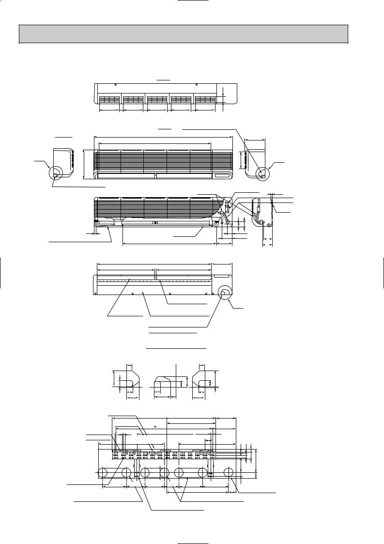
PK-4FLSD |
Unit : mm |
PK-4FLSD1 |
|
PK-4FLSD2 |
Top |
|
|
|
62.5 |
235 |
45 |
235 |
45 |
235 |
45 |
235 |
45 |
235 |
13 |
|
Front |
Knock out hole for right piping |
|
|
Right side |
Left side |
1680 |
235 |
|
1370 Air intake |
|
|
|
|
A |
|
197 |
340 |
|
C
Knock out hole for left piping
Liquid pipe Terminal block for control |
15 |
Bolt
|
|
|
|
42 |
58 |
|
|
25 |
|
Drain hose |
|
55 (Gas pipe) |
|
||
|
|
|
102 |
||||
Drain hose for left-hand side piping |
|
|
|
||||
1110 |
Drain hose |
183 |
120 |
111 |
|||
|
|||||||
|
|
|
|
|
(Liquid pipe) |
|
|
Terminal block for power supply Gas pipe
|
Gas pipe 19.05(3/4F) |
Lower side |
Liquid pipe 9.52(3/8F) |
1400 |
240 |
694 Air outlet |
694 Air outlet |
|
Change vane (manual) |
|
|
Under panel |
B |
|
|
|
Auto vane |
(Removable at left-hand side piping) |
|
Knock out hole for under-piping
Refrigerant pipe. Drain pipe
Knock out hole for wiring
|
|
|
A |
|
B |
|
C |
|
|
|
|
|
|
|
|
|
30 |
|
|
|
30 |
|
|
|
|
|
|
|
100 |
39 |
|
|
39 |
37 |
65 |
39 |
100 |
|
|
|
|
|
|
4 |
37 |
|
32 |
37 |
|
4 |
|
|
|
|
|
|
|
74 |
|
98 |
74 |
|
|
|
|
|
|||
|
|
|
|
|
|
|
|
|
|
|
|||
|
Unit out line |
Unit center |
|
|
|
|
|
|
|
|
|||
|
1270 |
|
|
|
245 |
|
|
|
|
||||
|
|
|
|
|
|
|
|
|
|
|
|||
|
|
Wall fixture |
13 |
91=(1183) |
595 |
|
|
|
|
|
|
||
|
|
|
|
285 |
|
|
|
|
|||||
|
|
|
|
|
|
|
|
|
|
||||
84-ø6 hole for |
|
18 |
18 |
|
|
900 |
|
|
19 |
|
|
|
|
tapping screw |
|
Drainage range |
Drainage range |
91 |
|
|
|
|
|||||
|
|
|
on left-hand side |
on right-hand side |
|
|
10 |
30 |
29 |
|
|||
|
|
|
|
|
|
|
|
|
|
|
|||
|
|
|
|
|
|
|
|
|
|
184 |
30 |
80 |
280 |
|
|
|
|
|
|
|
|
|
|
|
|
|
60 |
41-ø12 hole for bolt |
295 |
225 |
240 |
180 |
280 |
|
314 |
30 |
|
|
|
||
|
|
|
|
|
|||||||||
|
|
|
|
|
|
|
750 |
|
|
90 |
Rear piping opening |
||
Range for left rear piping opening |
Range for left rear piping opening |
12-ø6 hole for tapping screw
14
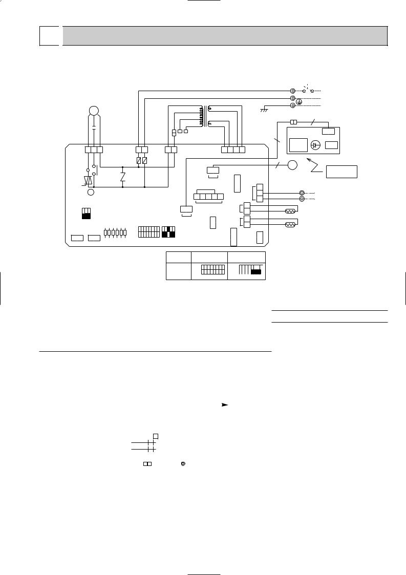
7 
 WIRING DIAGRAM
PK-2.5FLD PK-3FLD PK-4FLD PK-2.5FLD1 PK-3FLD1 PK-4FLD1 PK-2.5FLD2 PK-3FLD2 PK-4FLD2
|
|
MF |
|
|
|
|
|
|
|
|
|
220V |
|
|
10.6VAC |
|
||
|
|
|
|
|
|
|
|
|
|
|
|
|
|
|
|
|||
|
|
|
|
|
|
|
|
|
|
RED |
ORN |
YLW |
230V |
|
|
|
|
|
|
|
C |
|
|
|
|
|
|
|
240V |
|
|
14.5VAC |
|
||||
|
|
|
|
|
|
|
|
|
|
|
|
|
|
|
||||
|
|
|
|
|
|
|
|
|
|
|
|
|
T |
|
|
|
|
|
|
|
|
|
|
|
|
|
|
|
|
|
|
|
|
|
|
|
|
I.B |
RED |
WHT |
BLK |
|
|
|
|
RED |
BLU |
WHT YLW |
|
|
|
|
|
|
RED |
RED BRN |
|
|
|
|
|
|
|
|
|
|
|
||||||||
FAN1 |
1 |
3 |
5 |
|
|
|
|
CND |
1 3 |
1 |
3 |
CNT |
|
|
|
|
4 |
3 2 |
|
|
|
|
|
|
|
|
POWER |
|
|
|
TRANS |
|
|
|
|
|
|
|
|
|
|
|
|
|
|
F2 |
F1 |
|
|
|
|
|
|
|
|
|
|
|
|
X4 |
|
|
|
|
|
|
|
|
|
|
6 |
|
|
1 |
|
|
|
|
|
|
|
|
|
|
|
|
|
|
|
|
CN6V |
CN51 MULTIPLE |
||
|
|
|
|
|
|
|
|
|
|
|
|
|
|
|
VANE |
|
|
|
|
X4 |
|
|
|
|
ZNR |
|
|
|
|
1 |
2 |
3 |
4 |
5 |
|
||
|
|
|
|
|
|
|
|
|
|
|
|
|
|
|||||
|
SW3 |
|
|
|
|
|
|
|
|
7 |
|
1 |
CN50 |
|
CN21 |
|||
|
|
ON |
|
|
|
|
|
|
|
|
DRAIN |
|
PIPE |
|||||
|
|
|
|
|
|
|
|
|
|
|
|
|
||||||
|
|
OFF |
|
JR |
|
|
SW1 |
SW2 |
WIRELESS |
CN27 M.U.D |
|
INTAKE |
||||||
|
1 2 3 |
|
|
|
|
|
|
|
|
|
CN70 |
|
|
|
|
CN20 |
||
CN2B |
CN2A |
|
|
|
|
ON |
|
|
|
|
|
|
|
|
|
|
||
TWIN-2 |
TWIN-1 |
|
|
|
|
|
|
|
|
|
|
|
|
TIMER |
|
|||
|
|
|
|
OFF |
|
|
|
|
|
|
|
|
CN2 |
|||||
|
|
|
|
|
|
|
|
|
|
|
|
|
|
|
|
|||
|
|
|
|
|
|
|
|
|
|
|
|
|
|
|
|
|
|
|
|
|
|
1 |
2 |
3 |
4 |
5 |
6 |
1 2 3 4 5 6 7 8 1 2 3 4 5 |
|
|
|
|
|
|
|
||
GRN/YLW
BRN |
|
|
1 |
CN4T |
|
|
TRANS |
|
|
CN30 OUTDOOR |
1 2 3 |
|
2 |
|
|
1 |
|
|
2 |
|
|
1 |
|
|
CN28 TEST.L |
|
L |
POWER SUPPLY |
|
N~(1 PHASE) AC220-240V 50Hz AC220V 60Hz
TB2
7
|
Ru |
|
CNB |
W.B |
|
|
LD1 |
|
|
|
|
|
|
|
7 |
|
|
|
SW1 |
6 |
MV |
|
|
W.R |
|
|
|
REMOTE |
|
|
|
|
|
|
|
|
|
|
CONTROLLER |
ORN |
TB4 |
2 |
TO OUTDOOR UNIT |
|
|
||||
YLW |
|
1 |
CONNECTING WIRES |
|
|
|
|
DC12V |
|
RT2
RT1
|
|
MODELS |
PK-2.5FLD |
|
|
PK-4FLSD |
|
|
||||||||||
|
|
PK-3FLD |
|
|
|
|
||||||||||||
|
|
|
|
|
|
|
|
|
|
|
|
|
|
|
||||
|
|
SW1 |
|
ON |
|
|
ON |
|
|
|
|
|
|
|
|
|
|
|
|
|
|
|
|
|
|
|
|
|
|||||||||
|
|
|
OFF |
|
|
OFF |
|
|
|
|
|
|
|
|
|
|
||
|
|
|
|
|
|
|
|
|
|
|
|
|
|
|
||||
|
|
|
|
1 2 3 4 5 6 7 8 |
1 2 3 4 5 6 7 8 |
|
|
|
|
|||||||||
|
|
|
|
|
|
|
|
|
|
|
|
|
|
|
|
|
|
|
SYMBOL |
NAME |
SYMBOL |
|
|
|
NAME |
SYMBOL |
NAME |
||||||||||
|
|
|
|
|
|
|
|
|
|
|
|
|
|
|
|
|
||
C |
FAN MOTOR CAPACITOR |
MF |
FAN MOTOR |
|
|
|
|
|
|
|
|
|
TB2 |
TERMINAL BLOCK (POWER SUPPLY) |
||||
CN2<I.B> |
TIMER ADAPTOR CONNECTOR |
MV |
VANE MOTOR |
|
|
|
|
|
|
|
|
|
TB4 |
TERMINAL BLOCK |
||||
CN2A<I.B> |
TRANSMISSION WIRES No.1 CONNECTOR |
RT1 |
ROOM TEMPERATURE THERMISTOR |
(INDOOR/OUTDOOR CONNECTING WIRE) |
||||||||||||||
|
||||||||||||||||||
CN2B<I.B> |
TRANSMISSION WIRES No.2 CONNECTOR |
(0%/15k",25°C/5.4k" DETECT) |
X4<I.B> |
FAN MOTOR RELAY |
||||||||||||||
|
||||||||||||||||||
CN27<I.B> |
DRAIN LIFE-UP MECHANISM |
RT2 |
PIPE TEMPERATURE THERMISTOR |
ZNR |
VARISTOR |
|||||||||||||
CN28<I.B> |
TIME SHORTENING CONNECTOR |
(0%/15k". 25%/5.4k" DETECT) |
SW1<W.B> |
ON/OFF SWITCH |
||||||||||||||
|
||||||||||||||||||
CN51<I.B> |
MULTIPLE CONNECTOR |
Ru<W.B> |
RECEIVING SELECTOR UNIT |
LD1<W.B> |
LED (RUN INDICATOR) |
|||||||||||||
F1,2<I.B> |
FUSE(6.3A 250V) |
SW1<I.B> |
FUNCTION SELECTOR SWITCH |
W.B |
WIRELESS REMOTE CONTROLLER BOARD |
|||||||||||||
I.B |
INDOOR CONTROLLER BOARD |
SW2<I.B> |
UNIT SELECTOR SWITCH |
W.R |
WIRELESS REMOTE CONTROLLER |
|||||||||||||
JR |
JUMPER RESISTORS (FUNCTION SELECTOR) |
SW3<I.B> |
EMERGENCY OPERATION SWITCH |
|
|
|||||||||||||
|
|
T |
TRANSFORMER |
|
|
|
|
|
|
|
|
|
|
|
||||
NOTES:
1. Since the indoor fan motor (MF) is connected with 220V power, using 230, 240V power will require a setting change of the dip switch (SW1<I.B>) on the indoor controller board as shown in fig:w1.
|
|
|
|
|
SW1 |
|
|
|
|
|
SW1 |
||||||||||
|
|
ON |
|
|
|
|
|
|
|
|
|
|
ON |
|
|
|
|
|
|
|
|
|
|
|
|
|
|
|
|
|
|
|
|
|
|
|
|
|
|
||||
fig w1 |
Indoor fan motor (MF) for 230,240V. |
|
|
|
|
|
|
|
|
|
|
|
|
|
|
|
|
||||
|
|
OFF |
|
|
|
|
|
|
|
|
|
|
OFF |
|
|
|
|
|
|
|
|
|
|
||||||||||||||||||||
|
|
1 |
2 3 4 5 6 7 8 |
1 |
2 3 4 5 6 7 8 |
||||||||||||||||
2.Since the outdoor side electric wiring may change be sure to check the outdoor unit electric wiring for servicing.
3.Since the indoor transformer (T) is connected with 220V power, if 230,240V power is used. Change the wiring connection showing fig * : 2.
|
|
|
|
|
|
220V |
RED |
|
|
|
|
|
|
|
|||
|
|
|
|
|
|
|
|
|
|
fig w2 |
When power supply is 230V |
|
|
|
230V |
ORANGE |
|
|
|
|
|
|
|
|
|
|
|
|
220V |
|
|
|
240V |
YELLOW |
|
|
|
|
|
|
|
|||
4. Symbols used in wiring diagram above are, |
: Connector, |
: Terminal block. |
||||||
5. Emergency operation
If remote controller or microcomputer fails but there is no other trouble, emergency operation is possible by setting dip switch (SW3<I.B>) on the indoor controller board.
[Check items]
(1)Compressor and fan.
(2)Check the trouble position using self diagnostic function. If the result of self diagnosis indicates protective device such as freeze protection is functioning
emergency operation is not possible unless the cause is removed.
Emergency operation will be continuous operation mode due to power ON/OFF (ON/OFF with remote controller is not possible). [Emergency operation procedure]
(1)Set the dip switch (SW3 <I.B>) on the indoor controller board to 1 • 2 on and 3 off for cooling.
(2)Turn on outdoor unit side circuit breaker, then indoor unit side circuit breaker in this order.
(3)During emergency operation indoor fan runs at high speed but automatic vane remains stop. If vane is closed, open the vane by hands.
(4)Thermostat will not function.
(5)Emergency cooling should be limited to 10 hours maximum. (The indoor unit heat exchanger may freeze).
15
 Loading...