


PEFY-P20VMM-A
Mitsubishi PEFY-P20VMM-A, PEFY-P25VMM-A, PEFY-P32VMM-A, PEFY-P40VMM-A, PEFY-P50VMM-A Service Manual
...
TECHNICAL & SERVICE MANUAL
Air-Conditioners For Building Application
<Indoor unit>
PEFY-P20VMM-A,PEFY-P71VMM-A
PEFY-P25VMM-A,PEFY-P80VMM-A
PEFY-P32VMM-A,PEFY-P100VMM-A
PEFY-P40VMM-A,PEFY-P125VMM-A
PEFY-P50VMM-A,PEFY-P140VMM-A
PEFY-P63VMM-A
2001
Models
INDOOR UNIT
Ceiling Concealed
Series PEFY
CONTENTS
SAFETY PRECAUTIONS·························1
1. FEATURES············································3
2. PART NAMES AND FUNCTIONS········4
3. SPECIFICATION ···································6
4. OUTLINES AND DIMENSIONS············8
5.WIRING DIAGRAM ·····························10
6.
REFRIGERANT SYSTEM DIAGRAM
····12
7.TROUBLE SHOOTING························13
8. DISASSEMBLY PROCEDURE···········18
For use with the R407C & R22
SAFETY PRECAUTIONS
- Inadequate connection and fastening may generate heat and
cause a fire.
• Prepare for ty phoons and othe r str ong wi nds an d earthquak es
and install the unit at the specified place.
- Improper in stal lati on may cause th e unit to to pple and re sult in
injury.
• Always use an air c leaner, humidi fie r, electric hea ter, and other
accessories specified by Mitsubishi Electric.
- Ask an authorized technician to install the accessories. Improper
installati on by th e user may re sult in water leakag e, el ectric shoc k,
or fire.
• Never repair the uni t. If the air con dit ion er must be rep air ed,
consult the dealer.
- If the unit is repaired improperly, water leakage , electric shoc k, or
fire may result.
• Do not touch the heat exchanger fins.
- Improper handling may result in injury.
• If refrigerant gas leaks during installation work, ventilate the
room.
- If the refrigerant gas comes into contact with a flame, poisonous
gases will be released.
• Install the ai r cond itio ner ac cor ding to th is In stalla tion Man ual.
- If the unit is installed improperly, water leakage , electric shoc k, or
fire may result.
• Have all electr ic w ork don e b y a lic ensed ele ctrici an accor din g
to “Electric Facility Engineering Standard” and “Interior Wire
Regulations”and the instructions given in this manual and always use a special circuit.
- If the power source capacity is inadequa te or elec tric work is per-
formed improperly, electric shock and fire may result.
• Securely install the cover of control box and the panel.
- If the cov er and pan el are not ins tal led pro perly,dust or w ate r may
enter the outdoor unit and fire or electric shock may result.
• When installi ng an d mo ving the air co ndit ione r to anot her si te,
do not charge the it with a refrigerant differen t fr om the refrigerant (R407C or R22) specified on the unit.
- If a different refriger ant or air is mixed wit h the original refriger ant,
the refrigerant cycle may malfunction and the unit may be damaged.
• If the air conditioner is installed in a small room, measures
must be take n to pr event th e re fr ig er ant co ncen tr at ion from
exceeding the safety limit even if the refrigerant should leak.
- Consult the de aler rega rdin g the ap propr ia te me asures to pre-
vent the safety limit from being exceeded. Should the refrigerant
leak and cause th e safety li mit to be exceed ed , haza rds du e to
lack of oxygen in the room could result.
• When moving and reinstalling the air conditioner, consult the
dealer or an authorized technician.
- If the air conditioner is installed improperly, water leakage, elec-
tric shock, or fire may result.
• After completing installation work, make sure that refrigerant
gas is not leaking.
- If the refrigerant gas leaks and is exposed to a fan heater, stove,
oven, or other heat source, it may generate noxious gases.
• Do not re cons tr uc t or chan g e th e se ttin gs of the prote ct ion
devices.
- If the pressure switch, thermal switch, or other protection device
is shorted an d op erat ed f orci bly, or parts ot her th an th ose spec ified
by Mitsubishi Electric are used, fire or explosion may result.
1. Befor e instal lati on and elec tric work
s Before installing the unit, make sure you read all the
“Safety precautions”.
s The “Safety precautions” provide very important
points regarding safety. Make sure you follow them.
s This equipment may not be applicable to EN61000-3-
2: 1995 and EN61000-3-3: 1995.
s This equipment may cause the adverse effect on the
same supply system.
s Please report to or take consent by the supply au-
thority before connection to the system.
Symbols used in the text
Warning:
Describes precautions that should be observed to prevent danger
of injury or death to the user.
Caution:
Describes pr ecau tion s that shou ld be obse rved to pre vent dama ge
to the unit.
Symbols used in the illustrations
: Indicates an action that must be avoided.
: Indicates that important instructions must be followed.
: Indicates a part which must be grounded.
: Indicates tha t cau tion should be taken wit h rot ati ng parts. (This
symbol is displayed on the main unit label.) <Color: Yellow>
: Beware of electric shock (This sym bol is dis played on the main
unit label.) <Color: Yellow>
Warning:
Carefully read the labels affixed to the main unit.
Warning:
• Ask the dealer or an aut horized tec hnicia n to instal l the air conditioner.
- Improper installatio n b y the use r ma y result in w ater lea kage , elec -
tric shock, or fire.
• Install the air unit at a place that can withstand its weight.
- Inadequate str eng th may cause the uni t to fall down, res ult ing in
injuries.
• Use the specified cables for wiring. Make the connections securely so th at th e ou tsid e f or ce of th e ca ble is no t ap plie d to the
terminals.
1

2. Precautions for devices that use
R407C refrigerant
Caution:
• Do not use the existing refrigerant piping.
- The old refrigerant and refrigerator oil in the existing piping contains a large amount of chlorine which may cause the refrigerator
oil of the new unit to deteriorate.
• Use refriger ant pi ping made of ph osph orus
per.
deoxidized cop-
In addition, be sure
that the inner and outer surfaces
of the pipes are clean and
free of hazardous sulphur, oxides,
dust/dirt, shaving particles,
minant.
oils, moisture, or any other conta-
- Contaminan ts on th e in si de of the re fr ig er an t pi pi ng may caus e
the refrigerant residual oil to deteriorate.
• Store th e pipi ng to be us ed du ring inst alla tion indo or s and keep
both ends of the piping sealed until just before brazing. (Store
elbows and other joints in a plastic bag.)
- If dust, dirt, or water enters the refrigerant cycle, deterioration of
the oil and compressor trouble may result.
• Use ester oil, ether oil or alk ylb enzene (small amo unt ) as the
refrigerator oil to coat flares and flange connections.
- The refrigerat or oi l wi ll de gr ade if it is mi x ed wi th a larg e am ount of
mineral oil.
• Use liquid refrigerant to fill the system.
- If gas refrigerant is used to seal the system, the composition of
the refrigera nt in the cyli nder will chan ge and pe rfor manc e may
drop.
• Do not use a refrigerant other than R407C.
- If another refrigerant (R22, etc.) is used, the chlorine in the refrig-
erant may cause the refrigerator oil to deteriorate.
• Use a vacuum pump with a reverse flow check valve..
- The vacuum pump oil may flow back into the refriger ant cycl e and
cause the refrigerator oil to deteriorate.
• Do not use the following tools that are used with conventional
refrigerants.
(Gauge manifold, charge hose, gas leak detector, reverse flow
check valve, refrigerant charge base, vacuum gauge, refrigerant recovery equipment)
- If the conventional refrigerant and refrigerator oil are mixed in the
R407C, the refrigerant may deteriorated.
- If water is mixed in the R407C, the refrige ra tor oil may deteriorate.
- Since R407C do es no t cont ain any ch lor in e, ga s leak dete ctor s
for conventional refrigerants will not react to it.
• Do not use a charging cylinder.
- Using a charging cylind er ma y caus e the re friger ant to de terior ate.
• Be especially careful when managing the tools.
- If dust, dirt, or water gets in the refr igerant cyc le, the ref rige rant
may deteriorate.
2

PEFY-P20VMM-A
PEFY-P25VMM-A
PEFY-P32VMM-A
PEFY-P40VMM-A
PEFY-P50VMM-A
PEFY-P63VMM-A
PEFY-P71VMM-A
PEFY-P80VMM-A
PEFY-P100VMM-A
PEFY-P125VMM-A
PEFY-P140VMM-A
2.2/ 2.5
2.8/ 3.2
3.6/ 4.0
4.5/ 5.0
5.6/ 6.3
7.1/ 8.0
8.0/9.0
9.0/ 10.0
11.2/ 12.5
14.0/ 16.0
16.0/18.0
FEATURES
1
Indoor unit
Ceiling Concealed
Series PEFY
Models
Cooling capacity/Heating capacity
kW
3
PART NAMES AND FUNCTIONS
2
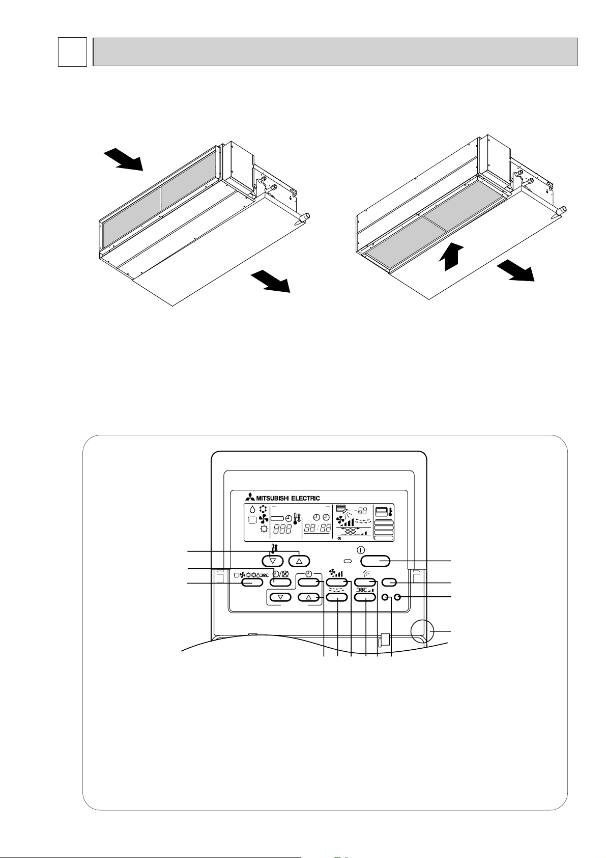
● Indoor (Main) Unit
● Remote controller
● Operation buttons
[PAR-20MAA]
●Once the controls are set, the same operation mode can
be repeated by simply pressing the ON/OFF button.
PAR-20MAA
ON/OFF
CENTRALLY CONTROLLED
ERROR CODE
CLOCK
ON OFF
˚C
CHECK
CHECK MODE
FILTER
TEST RUN
FUNCTION
˚C
1Hr.
NOT AVAILABLE
STAND BY
DEFROST
FILTER
CHECK TEST
TEMP.
TIMER SET
1
2
3
456879
0
C
A
B
Air inlet
Air outlet
1 [Room temperature adjustment] Button
2 [Timer/continuous] Button
3 [Selecting operation] Button
4 [Time selection] Button
[Time-setting] Button
5 [Louver] Button
6 [Fan speed adjustment] Button
Air inlet
Air outlet
[In case of rear inlet]
[In case of bottom inlet]
7 [Up/down airflow direction] Button
8 [Ventilation] Button
9 [Checking/built-in] Button
0 [Test run] Button
A [Filter] Button
B [ON/OFF] Button
C Position of built-in room temperature
•Never expose the remote controller to direct sunlight. Doing so can result in the erroneous measurement of room temperature.
•Never place any obstacle around the lower right-hand section of the remote controller.Doing so can
result in the erroneous measurement of room temperature.
4
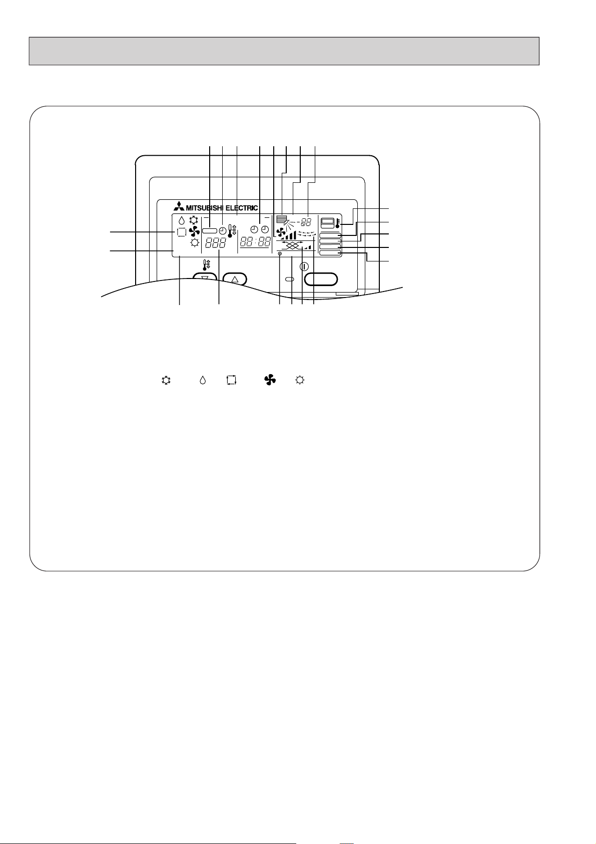
● Display
(A) Current time/Timer
(B) Centralized control
(C) Timer ON
(D) Abnormality occurs
(E) Operation mode: COOL, DRY, AUTO, FAN, HEAT
(F) Preparing for Heating mode
(G) Defrost mode
(H) Set temperature
(I) Power ON
(J) Louver
(K) Not available function
(L) Ventilation
(M) Function setting mode
(N) Test run mode
(O) Error check mode
(P) Filter sign
(Q)
Set effective for 1 hr.
(R) Sensor position
(S) Room temperature
(T) Airflow
(U) Fan speed
5
E
F
STAND BY
DEFROST
G
ABCD
CENTRALLY CONTROLLED
CHECK
TEMP.
˚C
ON OFF
CLOCK
ERROR CODE
HIKLJ
1Hr.
NOT AVAILABLE
SQTU
˚C
CHECK MODE
ON/OFF
FILTER
TEST RUN
FUNCTION
R
P
O
N
M
3
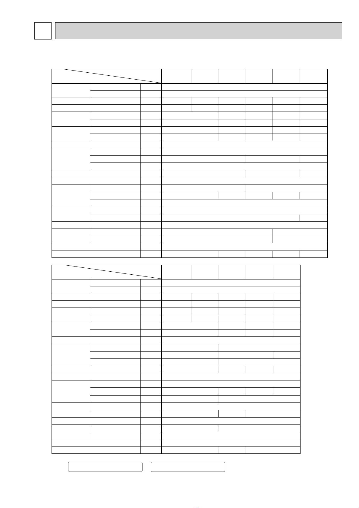
SPECIFICATION
3-1. Specification
Note: 1.Cooling / Heating capacity indicates the maximum value at operation under the following condition.
Cooling :Indoor 27¡CDB/19.0¡CWB Heating :Indoor 20¡C
:Outdoor 35¡CDB :Outdoor 7¡CDB/6¡CWB
2.The external static pressure is set to 50 Pa at factory shipment.
0.078
0.078
220-240
50
Galvanized steel plate
325
740
Cross fin( Alminium plate fin and copper tube)
Single phase induction motor
P.P. honeycomb
ø9.52
R1(External thread)
Power source
Model
PEFY-P20
VMM-A
PEFY-P25
VMM-A
PEFY-P32
VMM-A
PEFY-P40
VMM-A
PEFY-P50
VMM-A
Item
Dimension
Fan
Motor
Refrigerant
pipe dimension
Power consumption
Current
Cooling capacity
Heating capacity
External finish
Net weight
Heat exchanger
Air filter
Drain pipe dimension
Noise level
(Low-[Middle]-High)
Voltage
Frequency
Cooling
Heating
Cooling
Heating
Height
Width
Depth
Type
External static pressure
Type
Output
Gas(Flare)
Liquid(Flare)
~
/N V
Hz
kW
kW
kW
kW
A
A
mm
mm
mm
kg
m3/min
Pa
kW
mm
mm
dB
220-240
50
3.6
4.0
0.17
0.17
0.81
0.81
Galvanized steel plate
295
700
Cross fin( Alminium plate fin and copper tube)
7.5-9.0-10.5
30/50/100
Single phase induction motor
0.075
R1(External thread)
4.5
5.0
5.6
6.3
2.2
2.5
2.8
3.2
0.15
0.15
0.73
0.73
815
Note:1
Note:1
Note:1
Note:1
Note:2
Note:2
27
Sirocco fan
X
1
6.0-7.2-8.5 10.0-12.0-14.0 12.0-14.5-17.0
Sirocco fanX2
33
295
700
935
Airflow rate
(Low-[Middle]-High)
Power source
Model
PEFY-P71
VMM-A
PEFY-P63
VMM-A
PEFY-P80
VMM-A
PEFY-P100
VMM-A
PEFY-P125
VMM-A
Item
Dimension
Fan
Motor
Refrigerant
pipe dimension
Power consumption
Current
Cooling capacity
Heating capacity
External finish
Net weight
Heat exchanger
Air filter
Drain pipe dimension
Noise level
(Low-[Middle]-High)
Voltage
Frequency
Cooling
Heating
Cooling
Heating
Height
Width
Depth
Type
External static pressure
Type
Output
Gas(Flare)
Liquid(Flare)
~
/N V
Hz
kW
kW
kW
kW
A
A
mm
mm
mm
kg
m3/min
Pa
kW
mm
mm
dB
11.2
12.5
0.29
0.29
1.34
1.34
14.0
16.0
0.40
0.40
1.90
1.90
8.0
9.0
0.25
0.25
7.1
8.0
0.22
0.22
1.07
1.07
9.0
10.0
0.25
0.25
1.15
1.15
1,175
42
1,175
42
0.200
Sirocco fanX2
14.5-18.0-21.0
13.5-16.2-19.0
28.0-40.0
23.0-33.0
30/50/100 50/130
62 65
1,415 1,715
ø15.88 ø19.05
32-36-39
31-35-38
40-44 42-45
PEFY-P140
VMM-A
16.0
18.0
0.42
0.42
1.95
1.95
0.280
29.5-42.0
70
31-34-37 31-35-3828-32-3527-30-32
0.19
0.19
0.92
0.92
0.20
0.20
0.98
0.98
ø12.7
ø6.35
ø15.88
ø9.52
Airflow rate
(Low-[Middle]-High)
P.P. honeycomb
6
3-2. Electrical par ts specifications
7
Model
Parts
name
Transformer T (Primary) 50/60Hz 220-240V (Secondry) (18.4V 1.7A)
Room
temperature
thermistor
Liquid pipe
thermistor
Gas pipe
thermistor
Fuse
(Indoor con-
troller board)
Fan motor
(with Inner-
thermostat)
Innerthermostat
(Fan motor)
Symbol
MF1,2
PEFY-P20
VMM-A
TH21 Resistance 0˚C/15k
TH22 Resistance 0˚C/15k
TH23 Resistance 0˚C/15k½ ,10˚C/9.6k½ ,20˚C/6.3k½ ,25˚C/5.4k½ ,30˚C/4.3k½ ,40˚C/3.0k½
FUSE 250V 6.3A
PEFY-P25
VMM-A
4-pole Output 75W
D104P75MW
PEFY-P32
VMM-A
PEFY-P40
VMM-A
PEFY-P50
VMM-A
PEFY-P63
VMM-A
PEFY-P71
VMM-A
PEFY-P80
VMM-A
½ ,10˚C/9.6k½ ,20˚C/6.3k½ ,25˚C/5.4k½ ,30˚C/4.3k½ ,40˚C/3.0k½
½ ,10˚C/9.6k½ ,20˚C/6.3k½ ,25˚C/5.4k½ ,30˚C/4.3k½ ,40˚C/3.0k½
4-pole
Output 75W
D104P85MW
OFF 130˚C ± 5
ON 90˚C ± 20
4-pole Output 78W
D10CP95MW
PEFY-P100
NS-100VM-1
VMM-A
4-pole
Output
200W
PEFY-P125
VMM-A
4-pole
Output
280W
NS-125VM-1
PEFY-P140
VMM-A
an motor
F
capacitor
Linear
expansion valve
Power supply
terminal bed
Transmission
terminal bed
C1 8.0µFX µFX µFX µFX440V 8.0 440V 6.0 440V 8.0 440V
DC12V Stepping motor drive port
LEV
TB2 (L,N, ) 330V 30A
TB5
TB15
dimension ø3.2 (0~2000pulse)
EDM-402MD
(M1,M2,S)
(1,2)
300V 10A
DC12V Stepping motor drive
port dimension ø5.2 (0~20 00pulse)
EDM-804MD
DC12V
Stepping motor drive
por t dimension ø6.4
(0~2000pulse)
EDM-1004MD
 Loading...