

Mitsubishi Electric PAC-SH29TC-E Installation Manual
●Before starting installation, read the following safety precautions.
●The following precautions must be observed as it describes the serious matters for safety.
●
The safety precautions are described as follows with the degree of danger that occurs when the terminal block is handled wrong.
Describes precautions that must be observed to prevent danger of injury or death to the user.
Describes precautions that must be observed to prevent damage to the unit.
●After installation, make test operation and confirm that it works properly
Tell your customers to keep this installation manual together with the operation manual with them, and when they give or
sell this machine to other person put this installation manual and operation manual with it.
CAUTION
Ask installation to the dealer or an authorised technician.
If the terminal block is installed improperly by the customer, water leakage , electric shock, or fire may result.
Follow the installation manual to install the terminal block securely.
If the terminal block is installed improperly, water leakage , electric shock, or fire or other incidents may result.
Electrical wiring must be performed with electrical cables that do not exceed capacity.
Short circuit, heat generation, or fire may result.
WARNING
WARNING
Safety Precautions
CAUTION
WARNING
1. Outline
The terminal block is used as a relay to wire an indoor unit and two remote controllers or to wire a remote controller and multiple indoor units in order to perform grouping control.
2. Applicable model
Wall-mounting type (PKA-RP·KAL, PKA-RP·HAL)
3. Included parts
Terminal block (TB5) ·······1 Screw ·······1 Wire cable ·······1 (240 mm)
4. Installation procedure
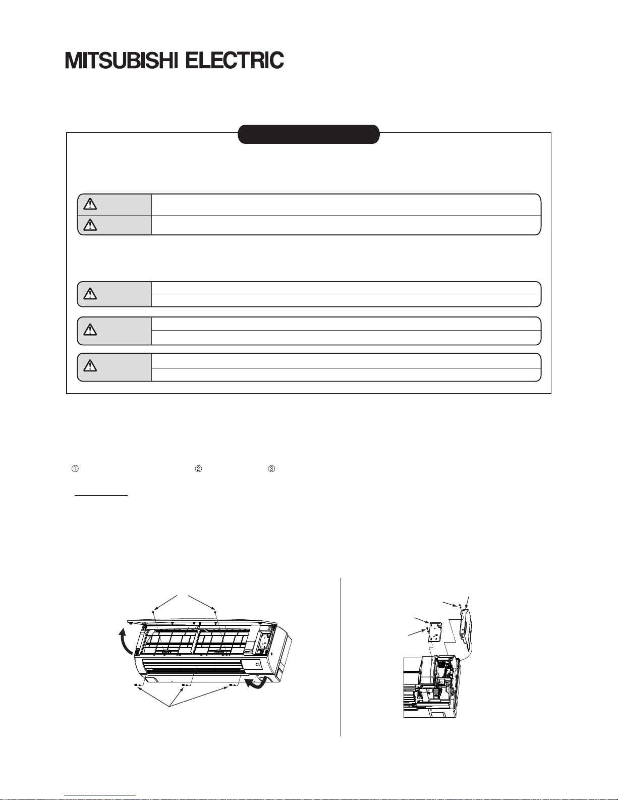
PKA-RP·KAL
1). Open the front grille and remove the 2 screws.
2). Remove the 3 screw covers and the 3 front panel screws.
3). Pull out the bottom of the front panel to the front.
Note: Beware that the panel does not contact with the vane while in the procedure.
4). Remove the terminal block cover and the control board cover by removing their respective screws.
Note: Be sure to keep the washers at hand.
Package Air Conditioner Optional Parts
Remote Controller Terminal Block Kit Installation Manual
Model No: PAC-SH29TC-E
Screws (2)
Pull out the bottom of the front
panel to the front.
Open the grill and
remove the 2 screws
Screw covers & screws (3)
Control board cover
Screw & washer
Electrical box cover
Screw & washer
Continued overleaf.
RG79L644H03
5). Secure terminal block with screw to the electrical control box.
6). Connect wire cable to terminal block and to connector CN22 on the indoor controller board.
7). Wire the wires of the cable that wire an indoor unit and 2 remote controllers or the cable that wire a remote con
troller and multiple indoor units for grouping control to the screw terminals at the bottom of terminal block .
Note: For more details about the methods for wiring the indoor unit and the remote controller(s), refer to the
installation manual attached with the appropriate indoor unit.
8). After the installation of the terminal block is complete, reinstall the removed parts in the reverse order.
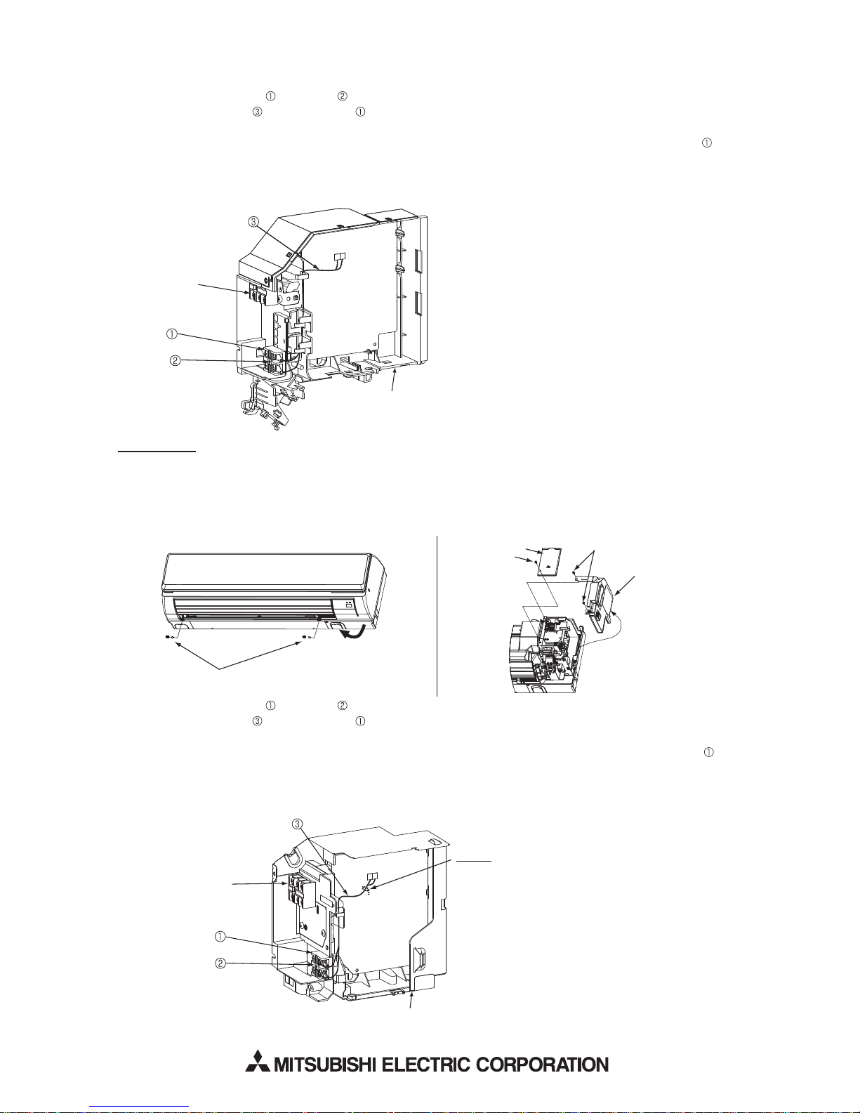
PKA-RP.HAL
1). Remove the 2 screw covers and the 2 front panel screws.
2). Pull out the bottom of the front panel to the front.
Note: Beware that the panel does not contact with the vane while in the procedure.
3). Remove the terminal block cover and the control board cover by removing their respective screws.
Control
(Indoor-outdoor
unit connection)
1
2
Controller board
Electrical control box
CN22 (BLU)
4). Secure terminal block with screw to the electrical control box.
5). Connect wire cable to terminal block and to connector CN22 on the indoor controller board.
6).
Wire the wires of the cable that wire an indoor unit and 2 remote controllers or the cable that wire a remote
controller and multiple indoor units for grouping control to the screw terminals at the bottom of terminal block .
Note: For more details about the methods for wiring the indoor unit and the remote controller(s), refer to the
installation manual attached with the appropriate indoor unit.
7). After the installation of the terminal block is complete, reinstall the removed parts in the reverse order.
Screw covers & screws (2)
Pull out the bottom of
the front panel to the front.
Control
(Indoor-outdoor
unit connection)
Controller board
Electrical control box
Fastener
Remove the fastener that ties the lead
wires together in the electrical control box,
and retie and refasten the lead wires together
with the lead wires from the terminal block.
1
2
CN22 (BLU)
Terminal board cover
Screw
Screws (2)
Control board cover
 Loading...