

Mitsubishi GB-50A Installation Manual
Mitsubishi Electric Air-conditioner Network System
Central Controller
Model: GB-50A
Before using the controller, please read this Installation Manual carefully to ensure correct
operation. Store this Installation Manual in a location that is easy to find.
1. Safety Precautions to be Observed without Fail..........1
2. Confirmation of Parts .................................................3
3. Product Feature.........................................................4
4. System Diagram ........................................................5
5. Installation Method ....................................................7
1. Part prepared at site..............................................7
2. Allowable length of M-NET transmission lines.........7
3. Installation method ................................................8
6. Wiring Method .........................................................11
1. Grounding cable. .................................................11
2. Cover removal and installation .............................11
3. M-NET transmission line ......................................12
4. LAN connection ...................................................12
7. Initial setting............................................................13
1. How to set the IP address with dip switches .........14
2. Setting of the service switch.................................14
8. Test Run .................................................................15
1. Collective operation ON/OFF ...............................15
2. Service LED display.............................................15
9. Example for System Configuration............................16
1. To control a K control model ................................16
2. To use system controllers on multiple units ..........16
10. External Input/Output Usage Method ......................16
1. External signal input function ...............................16
2. External signal output function .............................18
Installation Manual
Contents
This manual describes the installation of the central controller and wiring to the air conditioner. Refer to the
r
r
A
A
installation manual of the air conditioner. Carefully read item “1 Safety precautions to be observed without fail”
before installing the unit.
1 Safety Precautions to be Observed without Fail
* Hazards and levels of danger that can occur due to incorrect handling are classified by the following symbols.
WARNING Incorrect handling can result in death, serious injury, etc.
CAUTION Incorrect handling can result in injury or damage to the building or its contents.
* After reading this manual, keep in a handy place. When removing or repairing the unit, give this manual to the
installer. When the user changes, also give to the new user.
WARNING
Ask your dealer or technical
representative to install.
If incorrect installation is done by a customer, it
may cause an electric shock, fire, etc.
Securely install the controller according
to the installation manual.
If installation is not correct, it may cause an
electric shock, fire, etc.
Securely install in a place which can
withstand the weight of the controller.
If it is not enough, the unit may fall and
cause an injury.
Securely connect the wiring using the
specified cables and fix them so that the
stress from the cables is not applied to
the terminal connection sections.
If connection or fixing is not reliably
connected, it may cause heat generation, a
fire, etc.
The electric work should be perform by
authorized personal according to the
installation manual.
ny lack of electric circuit or any deficiency
caused by installation may result in an
electric shock or fire.
Do not move and re-install the unit by
yourself.
If installation is not correct, it may cause an
electric shock, fire, etc.
sk your dealer or technical representative.
Never modify or repair by yourself.
If the controller is modified or a repair is not
correct, it may cause an electric shock, fire,
etc.
Consult your dealer if repairs are necessary.
This appliance must be earthed (grounded).
Make sure to install a protect earth(PE)/grounding line .
Do not connect the PE (grounding) line to gas or water
pipes, lightning conductors or telephone grounding lines.
Improper grounding may cause an electric shock.
CAUTION
Do not install the controller in a place
where flammable gas could leak.
If gas leaks and collects around the unit, it
may cause a fire or explosion.
Do not use this controller in an
abnormal environment.
If the controller is used in a place where there is
much oil (including machine oil), steam o
sulfide gas, the performance of the controlle
may deteriorate or parts may be damaged.
Do not install this controller in a place
where the ambient temperature exceeds
40ºC (104ºF) or drops below 0ºC (32ºF),
also do not install in a place where it is
exposed to direct sunlight.
It may cause a deformation or malfunction.
Do not install this controller in a place
where steam is generated such as
bathroom, kitchen, etc.
Avoid placing where water condenses on
the walls. It may cause an electric shock or
malfunction.
1
Perform wiring so the tension is not
applied.
If tension is applied, it may cause
disconnection, heat generation or a fire.
Do not wash this controller with water.
It may cause an electric shock or
malfunction.
Use specified wires corresponding to
the current capacity for wiring.
Otherwise it may cause power leakage, heat
generation or
Do not touch the PCB (Printed Circuit
Board) with your hand or a tool. Also do
not get dirt on the PCB.
It may cause a fire or malfunction.
fire.
CAUTION
Do not install this controller in a place
where an acid or alkaline solution,
special spray, etc. is used frequently.
It may cause an electric shock or
malfunction.
Do not press the switches with sharp
objects.
It may cause an electric shock or
malfunction.
Do not connect an AC power source to the
M-NET terminal blocks of this device.
It may cause a breakdown or fire.
Do not touch the switches with wet hands.
It may cause an electric shock or
malfunction.
2
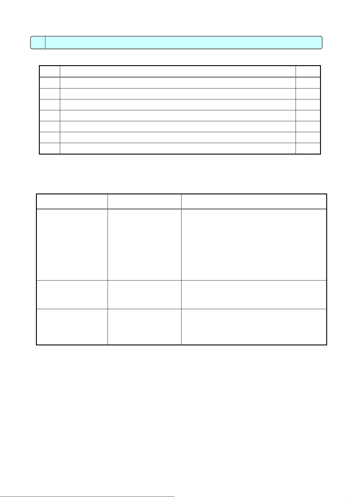
2 Confirmation of Parts
*Please confirm that in addition to this Installation Manual the following items are enclosed in the box.
No. Part name Qty.
1 Central controller 1
2 L-fitting 2
3 M3 (8mm (5/16in)) round head screw (for fixation of the fitting described in 2 above) 4
4 DIN rail attachment 2
5 M3 (6mm (1/4in)) round head screw (for fixation of the attachment described in 4 above) 8
6 Installation manual (this book) 1
7 Installation book 1
* The screws for installing to the control panel are not included. (M4 screws)
* In addition to the parts above, a power supply unit for transmission line, which supplies the power to the central controller
through the transmission line, must be purchased. When R410A, however, the power can be supplied also from the
R410A outdoor unit.
Unit that supplies the
power to GB-50A
The number of
connectable GB-50A
Remarks
PAC-SC50KUA 2 units *1 ● When only one GB-50A unit is connected
Up to three other system controllers can be
connected to the transmission line for central
control
(Up to three ON/OFF remote controllers, up to six
system remote controllers, up to six schedule
timers, or up to six group remote controllers can
be connected.)
● When two GB-50A units are connected
No other system controllers can be connected.
R410A outdoor unit
(connected to the
transmission line for
central control)
Outdoor unit other than
described above
1 unit Replace CN41 (power-supply switch connector) with
CN40 on only one outdoor unit.
Connectable number of indoor units will decrease by
4 units.
1 unit Connectable number of indoor units will decrease by
4 units.
(connected to
the indoor/outdoor
transmission line)
*1: Cannot be connected to the different transmission line for central control in the different system.
* Use PAC-SC50KUA (power supply unit) when “Charge” function is used, or multiple outdoor units are connected. Connect
only the M-NET terminal (TB2) on PAC-SC50KUA to the M-NET terminal on GB-50A.
3
6
)
3 Product Feature
1. Specification
Item Contents
Interface M-NET :DC30V/24V;0.13/0.15A
External I/O :DC12V or 24V (External power supply)
Ethernet :10Base-T
Environmental condition
Temperature Operating range 0 to 40ºC / 32 to 104ºF
Storage range -20 to 60º
Humidity 30~90%RH (No condensation)
Dimensions 130(H) x 250(W) x 38 (D) mm/5
Weight 1.1kg/2
1
/
lb
2
Installation Environment In the control panel box (indoor)
*This unit is installed and used in a business office or equivalent environment.
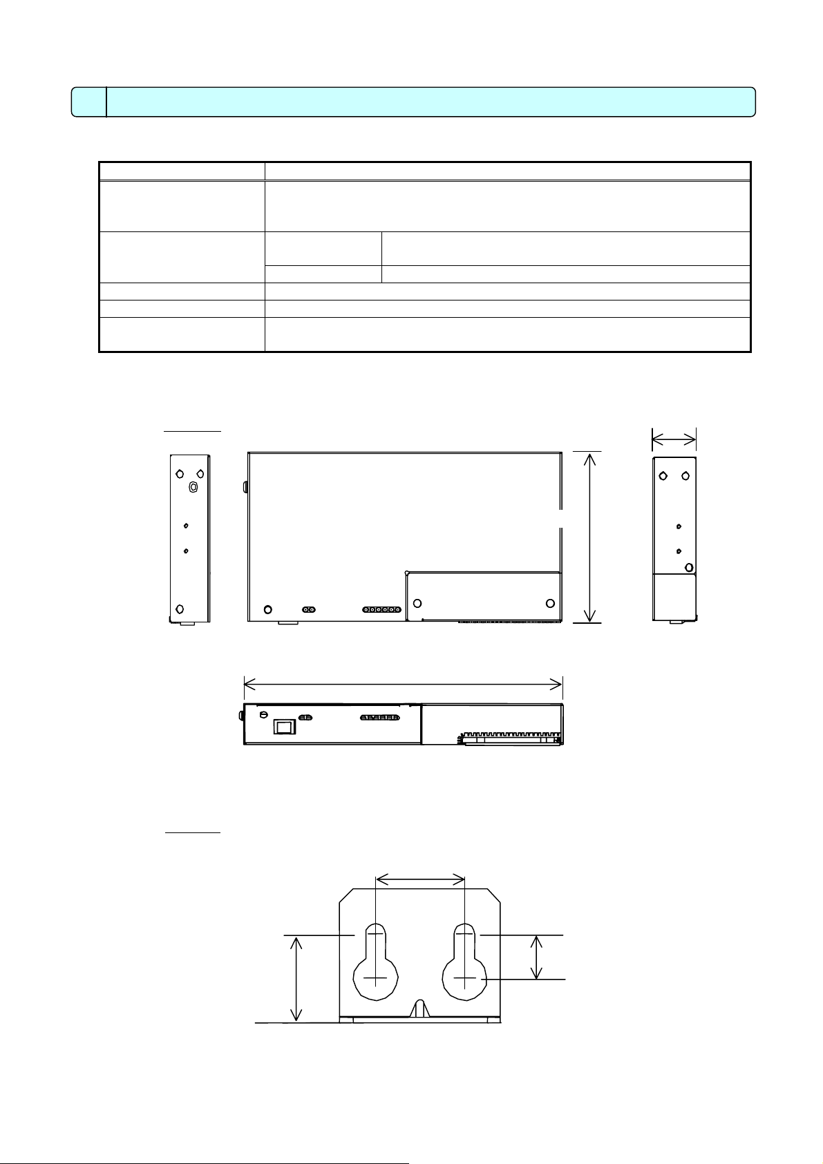
2. Outline dimensions
Main body
POWER LAN LINK/ACT 1 2 3 4 5
250 (97/8)
Fig. 3-1 Unit:mm(in)
L-fittings
20 (25/32
20 (25/32)
Fig. 3-2 Unit:mm(in)
1
/
(H) x9
8
C / -4 to 140ºF
7
/
(W) x 1
8
130 (51/8)
10 (25/64)
1
/
(D)in
2
38 (11/2)
4
)
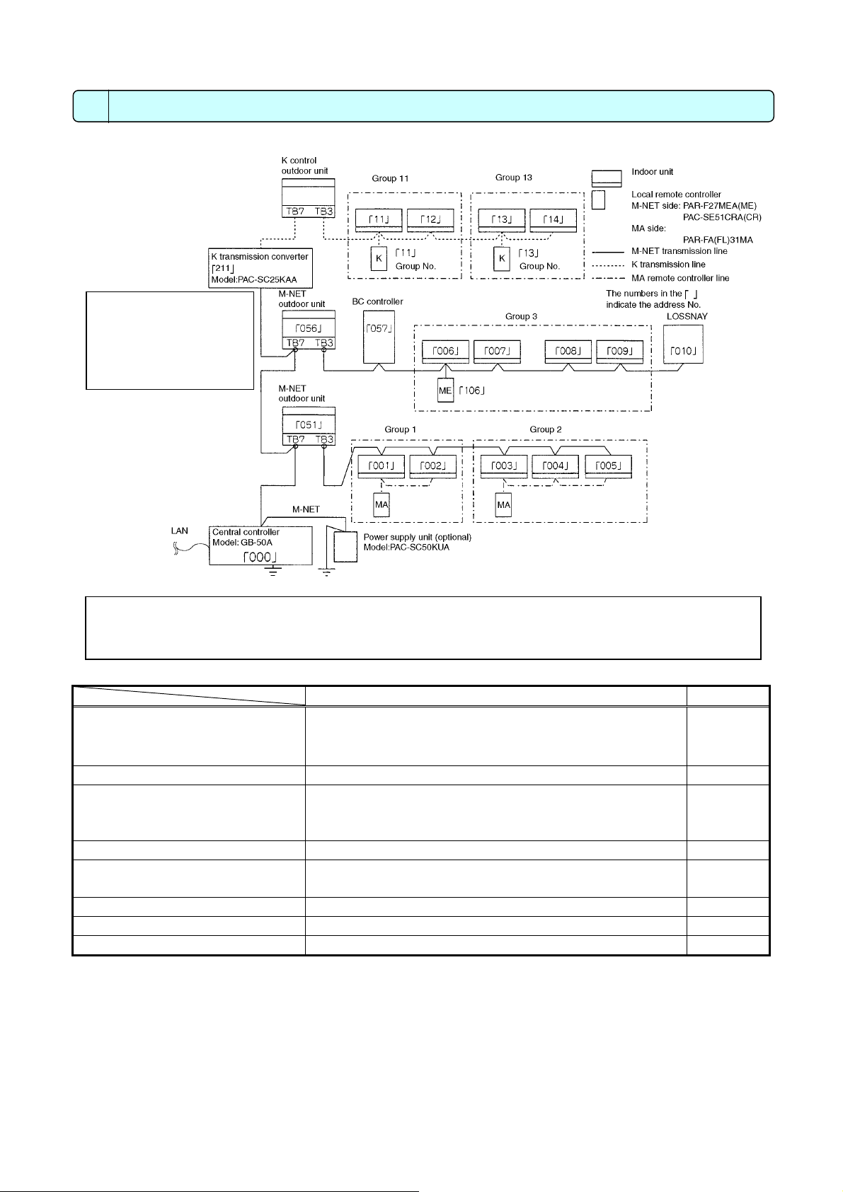
4 System Diagram
PAR -20/21MAA (MA
Note
●This diagram does not show
the AC power supply wiring.
Only the configuration for the
transmission line is shown.
* Address setting for each M-NET device (The address cannot be duplicated.)
* The K transmission converter (PAC-SC25KAA) and OA processing unit (LOSSNAY) are not included in
systems shipped to North America (USA & Canada).
Address setting method Address
Indoor unit Set the indoor unit you want to make them master unit in
the same group to the minimum address, and sequentially
set the indoor unit address in the same group.
Outdoor unit Min. indoor unit address in same refrigerant system + 50 51-100
BC controller/OS controller
* OS: Subsidiary Outdoor unit
K control side remote controller Same address as indoor unit master unit 1-50
M-NET remote controller Set to the minimum indoor unit master address in the
MA remote controller Address setting is unnecessary. OA processing unit/LOSSNAY After setting all the indoor units, set an arbitrary address. 1-50
K transmission converter Min. address of K control indoor unit + 200 201-250
Outdoor unit address in same refrigerant system + 1
However, for Sub-BC controller, minimum indoor unit
address that connects the local refrigerant piping + 50.
same group + 100.
1-50
52-100
101-200
5
 Loading...