

Page 1
TRANSISTORIZED INVERTER
FR-F500J
INSTRUCTION MANUAL (Detailed)
AIR-CONDITIONING INVERTER
FR-F520J-0.4K to 15K (F)
FR-F540J-0.4K to 15K (F)
WIRING
FUNCTIONS
PROTECTIVE
FUNCTIONS
SPECIFICATIONS
Chapter 1
Chapter 2
Chapter 3
Chapter 4
Page 2
Thank you for choosing this Mitsubishi Transistorized inverter.
This instruction manual (detailed) provides instructions for advanced use of the FR-
F500J series inverters.
Incorrect handling might cause an unexpected fault. Before using the inverter, always
read this instruction manual and the instruction manual (basic) [IB-0600129E]
packed with the product carefully to use the equipment to its optimum.
This section is specifically about safety matters
Do not attempt to install, operate, maintain or inspect the inverter until you have read
through this instruction manual (basic) and appended documents carefully and can
use the equipment correctly. Do not use the inverter until you have a full knowledge
of the equipment, safety information and instructions.
In this instruction manual (detailed), the safety instruction levels are classified into
"WARNING" and "CAUTION".
WARNING
CAUTION
Assumes that incorrect handling may cause hazardous
conditions, resulting in death or severe injury.
Assumes that incorrect handling may cause hazardous
conditions, resulting in medium or slight injury, or may cause
physical damage only.
Note that even the level may lead to a serious consequence
according to conditions. Please follow the instructions of both levels because they are
important to personnel safety.
CAUTION
1. Electric Shock Prevention
WARNING
zWhile power is on or when the inverter is running, do not open the front cover. You
may get an electric shock.
zDo not run the inverter with the front cover removed. Otherwise, you may access
the exposed high-voltage terminals or the charging part of the circuitry and get an
electric shock. Also, the inverter’s ability to withstand earthquakes will deteriorate.
zEven if power is off, do not remove the front cover except for wiring or periodic
inspection. You may access the charged inverter circuits and get an electric shock.
zBefore starting wiring or inspection, check to make sure that the 3-digit LED inverter
monitor is off, wait for at least 10 minutes after the power supply has been switched off,
and check to make sure that there are no residual voltage using a tester or the like.
zThis inverter must be earthed (grounded). Earthing (grounding) must conform to
the requirements of national and local safety regulations and electrical codes.
(NEC section 250, IEC 536 class 1 and other applicable standards)
zAny person who is involved in the wiring or inspection of this equipment should be
fully competent to do the work.
zAlways install the inverter before wiring. Otherwise, you may get an electric shock
or be injured.
zPerform setting dial and key operations with dry hands to prevent an electric shock.
You may get an electric shock.
zDo not subject the cables to scratches, excessive stress, heavy loads or pinching.
Otherwise you may get an electric shock.
zDo not change the cooling fan while power is on. It is dangerous to change the
cooling fan while power is on.
A-1
Page 3
2. Fire Prevention
CAUTION
zInstall the inverter (filter pack) on an incombustible wall without holes, etc.
Mounting it to or near combustible material can cause a fire.
zIf the inverter has become faulty, switch off the inverter power. A continuous flow of
large current could cause a fire.
z
Do not connect the resistor directly to the DC terminals P and N. This coule cause a fire.
3. Injury Prevention
CAUTION
zApply only the voltage specified in the instruction manual to each terminal to
prevent damage, etc.
zAlways connect to the correct terminal to prevent damage, etc.
zAlways make sure that polarity is correct to prevent damage, etc.
zWhile power is on or for some time after power-off, do not touch the inverter (filter
pack) or break register as they are hot and you may get burnt.
4. Additional Instructions
Also note the following points to prevent an accidental failure, injury, electric shock,
etc.
(1) Transportation and installation
CAUTION
zWhen carrying products, use correct lifting gear to prevent injury.
zDo not stack the inverter boxes higher than the number recommended.
zEnsure that installation position and material can withstand the weight of the
inverter. Install according to the information in the instruction manual.
zDo not install or operate if the inverter (filter pack) is damaged or has parts missing.
zWhen carrying the inverter, do not hold it by the front cover or setting dial; it may fall
off or fail.
zDo not stand or rest heavy objects on the inverter.
zCheck the inverter mounting orientation is correct.
zPrevent other conductive bodies as screws and metal fragments or other
flammable substance as oil from entering the inverter (filter pack).
zAs the inverter (filter pack) is a precision instrument, do not drop or subject it to impact.
zUse the inverter under the following environmental conditions: This could cause the
inverter (filter pack) damage.
Surrounding Air
Temperature
Ambient
humidity
Storage
temperature
Atmosphere
Environment
Altitude/
vibration
*1 Temperatures applicable for a short time, e.g. in transit.
*2 When using with the filter pack installed on the rear panel of the FR-F520J-15K or
FR-F540J-15K, do not install this combination on moving objects or places that
have vibrations exceeding 1.96m/s
-10°C to +50°C (non-freezing)
90%RH maximum (non-condensing)
-20°C to +65°C *1
Indoors (free from corrosive gas, flammable gas, oil mist,
dust and dirt)
Max.1000m above sea level 5.9m/s
2
.
2
or less *2
A-2
Page 4
(2) Wiring
CAUTION
zDo not fit capacitive equipment such as power factor correction capacitor, radio
noise filter (option FR-BIF(-H)) or surge suppressor to the output of the inverter.
zThe connection orientation of the output cables U, V, W to the motor will affect the
direction of rotation of the motor.
(3) Trial run
CAUTION
zCheck all parameters, and ensure that the machine will not be damaged by a
sudden start-up.
zWhen the load GD
output current may vary when the output frequency is in the 20Hz to 30Hz range.
If this is a problem, set the Pr.72 "PWM frequency selection" to 6kHz or higher.
(When setting the PWM to a higher frequency, check for noise or leakage current
problem and take countermeasures against it.)
(4) Operation
2
is small (at the motor GD or smaller) for 400V from 1.5K to 3.7K, the
WARNING
zWhen you have chosen the retry function, stay away from the equipment as it will
restart suddenly after an alarm stop.
zSince the key is valid only when functions are set (refer to page 116),
provide a circuit and switch separately to make an emergency stop (power off,
mechanical brake operation for emergency stop, etc).
zMake sure that the start signal is off before resetting the inverter alarm. A failure to
do so may restart the motor suddenly.
zThe load used should be a three-phase induction motor only. Connection of any other
electrical equipment to the inverter output may damage the equipment.
zDo not modify the equipment.
zDo not perform parts removal which is not instructed in this manual. Doing so may
lead to fault or damage of the inverter.
STOP
RESET
A-3
Page 5
CAUTION
zThe electronic thermal relay function does not guarantee protection of the motor
from overheating.
zDo not use a magnetic contactor on the inverter input for frequent starting/stopping
of the inverter.
zUse a noise filter to reduce the effect of electromagnetic interference. Otherwise
nearby electronic equipment may be affected.
zTake measures to suppress harmonics. Otherwise power supply harmonics from
the inverter may heat/damage the power capacitor and generator.
zWhen a 400V class motor is inverter-driven, please use an insulation-enhanced
motor or measures taken to suppress surge voltages. Surge voltages attributable to
the wiring constants may occur at the motor terminals, deteriorating the insulation of
the motor.
zWhen parameter clear or all clear is performed, reset the required parameters
before starting operations.
zThe inverter can be easily set for high-speed operation. Before changing its setting,
fully examine the performances of the motor and machine.
zIn addition to the inverter's holding function, install a holding device to ensure safety.
zBefore running an inverter which had been stored for a long period, always perform
inspection and test operation.
(5) Emergency stop
CAUTION
zProvide a safety backup such as an emergency brake which will prevent the
machine and equipment from hazardous conditions if the inverter fails.
zWhen the breaker on the inverter primary side trips, check for the wiring fault (short
circuit), damage of the inner parts of the inverter, etc. Identify the cause of the trip,
then remove the cause and power on the breaker.
zWhen any protective function is activated, take the appropriate corrective action,
then reset the inverter, and resume operation.
(6) Maintenance, inspection and parts replacement
CAUTION
zDo not carry out a megger (insulation resistance) test on the control circuit of the
inverter.
(7) Disposing of the inverter
CAUTION
zTreat as industrial waste.
(8) General instructions
Many of the diagrams and drawings in this instruction manual show the inverter without a
cover, or partially open. Never run the inverter in this status. Always replace the cover and
follow this instruction manual when operating the inverter.
A-4
Page 6

CONTENTS
1. WIRING 1
1.1 Standard connection diagram and terminal specifications........... 2
1.1.1 Standard connection diagram ......................................................................... 2
1.1.2 Explanation of main circuit terminals............................................................... 3
1.2 Main circuit terminals.................................................................... 7
1.2.1 Terminal block layout ...................................................................................... 7
1.2.2 Cables, wiring length, and crimping terminals................................................. 8
1.2.3 Wiring instructions ........................................................................................... 9
1.2.4 Selection of peripheral devices ..................................................................... 10
1.2.5 Leakage current and installation of earth (ground) leakage circuit breaker .. 11
1.2.6 Power-off and magnetic contactor (MC)........................................................ 15
1.2.7 Regarding the installation of the reactor........................................................ 16
1.2.8 Regarding noise (EMI) and the installation of a noise filter ........................... 17
1.2.9 Earthing (Grounding) precautions ................................................................. 18
1.2.10 Power supply harmonics............................................................................... 19
1.2.11 Harmonic suppression guideline ................................................................... 20
1.2.12 Inverter-driven 400V class motor .................................................................. 24
1.3 How to use the control circuit terminals ...................................... 25
1.3.1 Terminal block layout .................................................................................... 25
1.3.2 Wiring instructions ......................................................................................... 25
1.3.3 Changing the control logic............................................................................. 26
1.4 Input terminals............................................................................ 28
1.4.1 Run (start) and stop (STF, STR, STOP) ....................................................... 28
1.4.2 Connection of frequency setting potentiometer and
output frequency meter (10, 2, 5, 4, AU) ....................................................... 31
1.4.3 External frequency selection (REX, RH, RM, RL)......................................... 32
1.4.4 Indicator connection and adjustment (FM).................................................... 34
1.4.5 Control circuit common terminals (SD, 5, SE)............................................... 36
1.4.6 Signal inputs by contactless switches ........................................................... 36
1.5 How to use the input signals
(assigned terminals AU, RM, RH, STR) ..................................... 37
1.5.1 Multi-speed setting (RL, RM, RH, REX signals):
Pr. 60 to Pr. 63 setting "0, 1, 2, 8"
Remote setting (RL, RM, RH signals):
Pr. 60 to Pr. 63 setting "0, 1, 2" ..................................................................... 37
1.5.2 Second function selection (RT signal): Pr. 60 to Pr. 63 setting "3" ............... 37
1.5.3 Current input selection "AU signal": Pr. 60 to Pr. 63 setting "4" .................... 37
1.5.4 Start self-holding selection (STOP signal): Pr. 60 to Pr. 63 setting "5" ......... 38
1.5.5 Output shut-off (MRS signal): Pr. 60 to Pr. 63 setting "6" ............................. 38
CONTENTS
I
Page 7

1.5.6 External thermal relay input: Pr. 60 to Pr. 63 setting "7"................................39
1.5.7 Jog operation (JOG signal): Pr. 60 to Pr. 63 setting "9".................................39
1.5.8 Reset signal: Pr. 60 to Pr. 63 setting "10"......................................................40
1.5.9 PID control valid terminal: Pr. 60 to Pr. 63 setting "14"..................................41
1.5.10 PU operation/external operation switchover: Pr. 60 to Pr. 63 setting "16".....41
1.6 Connection to the stand-alone option .........................................42
1.6.1 Connection of the brake unit (FR-BU2)..........................................................42
1.6.2 Connection of the brake unit (FR-BU)............................................................44
1.6.3 Connection of the brake unit (BU type)..........................................................45
1.6.4 Connection of the high power factor converter (FR-HC)................................46
1.6.5 Connection of the power regeneration common converter (FR-CV)..............47
1.7 Handling of the RS-485 connector..............................................48
1.7.1 Connection of the parameter unit (FR-PU04) ................................................48
1.7.2 Wiring of RS-485 communication ..................................................................48
1.8 Design information ...................................................................... 52
1.9 Failsafe of the system which uses the inverter ...........................53
2. FUNCTIONS 57
2.1 Function (Parameter) list.............................................................58
2.2 List of parameters classified by purpose of use..........................71
2.3 Explanation of functions (parameters) ........................................73
2.3.1 Torque boost (Pr. 0 , Pr. 46 ) .........................................................................73
2.3.2 Maximum and minimum frequency (Pr. 1 , Pr. 2 ) .........................................74
2.3.3 Base frequency, base frequency voltage (Pr.3 , Pr.19 , Pr.47 ).....................75
2.3.4 Multi-speed operation (Pr. 4, Pr. 5, Pr. 6, Pr. 24 to Pr. 27, Pr. 80 to Pr. 87)..77
2.3.5 Acceleration/deceleration time (Pr. 7 , Pr. 8 , Pr. 20 , Pr. 44 , Pr. 45 ) ..........78
2.3.6 Selection and protection of a motor (Pr. 9 , Pr. 71 ).......................................80
2.3.7 DC injection brake (Pr. 10 , Pr. 11 , Pr. 12 ) ..................................................81
2.3.8 Starting frequency (Pr. 13 )............................................................................82
2.3.9 Load pattern selection (Pr. 14 )......................................................................83
2.3.10 Jog operation (Pr.15 , Pr.16 ).........................................................................84
2.3.11 RUN key rotation direction selection (Pr.17 ).................................................84
2.3.12 Stall prevention function and current limit function (Pr. 21 ) ..........................85
2.3.13 Stall prevention (Pr. 22 , Pr. 23 , Pr. 28 ) .......................................................87
2.3.14 Acceleration/deceleration pattern (Pr. 29 ) ....................................................89
2.3.15 Extended function display selection (Pr. 30 ).................................................90
2.3.16 Frequency jump (Pr. 31 to Pr. 36 )................................................................90
2.3.17 Speed display (Pr. 37 ) ..................................................................................91
2.3.18 Biases and gains of the frequency setting voltage (current)
(Pr. 38 , Pr. 39 , C2 to C7 ) ...........................................................................92
II
Page 8

2.3.19 Start-time earth (ground) fault detection selection (Pr. 40 ) .......................... 96
2.4 Output terminal function ............................................................. 96
2.4.1 Up-to-frequency sensitivity (Pr. 41 ) .............................................................. 96
2.4.2 Output frequency detection (Pr. 42 , Pr. 43 )................................................. 97
2.5 Current detection function .......................................................... 98
2.5.1 Output current detection functions (Pr. 48 , Pr. 49 )...................................... 98
2.5.2 Zero current detection (Pr. 50 , Pr. 51 )......................................................... 99
2.6 Display function ........................................................................ 100
2.6.1 Monitor display (Pr. 52 , Pr. 54 ).................................................................. 100
2.6.2 Setting dial function selection (Pr. 53 )........................................................ 101
2.6.3 Monitoring reference (Pr. 55 , Pr. 56 )......................................................... 102
2.7 Restart operation...................................................................... 102
2.7.1 Restart setting (Pr. 57 , Pr. 58 )................................................................... 102
2.8 Additional function .................................................................... 105
2.8.1 Remote setting function selection (Pr. 59 ) ................................................. 105
2.9 Terminal function selection....................................................... 109
2.9.1 Input terminal function selection (Pr. 60 , Pr. 61 , Pr. 62 , Pr. 63 ) .............. 109
2.9.2 Output terminal function selection (Pr. 64 , Pr. 65 ) .................................... 111
2.10 Operation selection function ..................................................... 112
2.10.1 Retry function (Pr. 66 , Pr. 67 , Pr. 68 , Pr. 69 ) .......................................... 112
2.10.2 PWM carrier frequency (Pr. 70 , Pr. 72 ) ..................................................... 114
2.10.3 Voltage input selection (Pr. 73 ) .................................................................. 115
2.10.4 Input filter time constant (Pr. 74 ) ................................................................ 116
2.10.5 Reset selection/PU stop selection (Pr. 75 )................................................. 116
2.10.6 Cooling fan operation selection (Pr. 76 )..................................................... 118
2.10.7 Parameter write disable selection (Pr. 77 ) ................................................. 119
2.10.8 Reverse rotation prevention selection (Pr. 78 )........................................... 120
2.10.9 Operation mode selection (Pr. 79 ) ............................................................. 120
2.10.10PID control (Pr. 88 to Pr. 94 )..................................................................... 124
2.11 Auxiliary function ...................................................................... 132
2.11.1 Slip compensation (Pr. 95 , Pr. 96 , Pr. 97 )................................................ 132
2.11.2 Automatic torque boost selection (Pr. 98 ) .................................................. 133
2.11.3 Motor primary resistance (Pr. 99 )............................................................... 134
2.12 Maintenance function ............................................................... 134
2.12.1 Maintenance output function (H1, H2 )........................................................ 134
2.12.2 Output phase failure protection selection (H8 )........................................... 135
2.13 Calibration parameters ............................................................. 137
2.13.1 Meter (frequency meter) calibration (C1 ) ................................................... 137
2.14 Clear parameters...................................................................... 140
2.14.1 Parameter clear (CLr )................................................................................. 140
III
CONTENTS
Page 9

2.14.2 Alarm history clear (ECL ) ............................................................................140
2.15 Communication parameters ...................................................... 141
2.15.1 Communication settings (n1 to n7 , n11 ) ...................................................143
2.15.2 Operation and speed command source (n8 , n9 ) .......................................158
2.15.3 Link startup mode selection (n10 )...............................................................159
2.15.4 EEPROM write selection (n12 ) ...................................................................161
2.16 Parameter unit (FR-PU04) setting.............................................162
2.16.1 PU display language selection (n13 ) ..........................................................162
2.16.2 PU buzzer control (n14 )..............................................................................162
2.16.3 PU contrast adjustment (n15 ) .....................................................................163
2.16.4 PU main display screen data selection (n16 )..............................................163
2.16.5 Disconnected PU detection/PU setting lock selection (n17 ) .......................164
3. PROTECTIVE FUNCTIONS 167
3.1 Errors (Alarms)..........................................................................168
3.1.1 Error (alarm) definitions ...............................................................................169
3.1.2 To know the operating status at the occurrence of alarm
(only when FR-PU04 is used)......................................................................177
3.1.3 Correspondence between digital and actual characters..............................177
3.1.4 Resetting the inverter ...................................................................................177
3.2 Troubleshooting ........................................................................178
3.2.1 Motor remains stopped ................................................................................178
3.2.2 Motor rotates in opposite direction...............................................................179
3.2.3 Speed greatly differs from the setting ..........................................................179
3.2.4 Acceleration/deceleration is not smooth ......................................................179
3.2.5 Motor current is large...................................................................................179
3.2.6 Speed does not increase .............................................................................179
3.2.7 Speed varies during operation .....................................................................179
3.2.8 Operation mode is not changed properly.....................................................180
3.2.9 Operation panel display is not operating......................................................180
3.2.10 Parameter write cannot be performed .........................................................180
3.2.11 Motor produces annoying sound..................................................................180
3.3 Precautions for maintenance and inspection ............................181
3.3.1 Precautions for maintenance and inspection...............................................181
3.3.2 Inspection item.............................................................................................181
3.3.3 Periodic inspection.......................................................................................181
3.3.4 Insulation resistance test using megger.......................................................182
3.3.5 Pressure test................................................................................................182
3.3.6 Daily and periodic inspection .......................................................................183
3.3.7 Replacement of parts...................................................................................186
3.3.8 Measurement of main circuit voltages, currents and powers .......................191
IV
Page 10

4. SPECIFICATIONS 195
4.1 Specification list........................................................................ 196
4.1.1 Ratings ........................................................................................................ 196
4.1.2 Common specifications............................................................................... 198
4.2 Outline dimension drawings ..................................................... 200
APPENDIX 205
APPENDIX 1 Parameter instruction code list..................................... 206
APPENDIX 2 SERIAL number check................................................. 211
CONTENTS
V
Page 11

1. WIRING
This chapter explains the basic "wiring" for use of this product. Always
read the instructions before use.
For description of "installation", refer to the instruction manual (basic).
1.1 Standard connection diagram and terminal
specifications .....................................................
1.2 Main circuit terminals ........................................ 7
1.3 How to use the control circuit terminals.......... 25
1.4 Input terminals.................................................... 28
1.5 How to use the input signals (assigned
terminals AU, RM, RH, STR) ..............................
1.6 Connection to the stand-alone option.............. 36
1.7 Handling of the RS-485 connector.................... 48
1.8 Design information............................................. 52
1.9 Failsafe of the system which uses the inverter 53
<Abbreviations>
•PU
Operation panel and parameter unit (FR-PU04)
•Inverter
Mitsubishi transistorized inverter FR-F500J series
•FR-F500J
Mitsubishi transistorized inverter FR-F500J series
•Pr.
Parameter number
•Filter pack
FR-BFP
2
37
Chapter 1
Chapter 2
Chapter 3
Chapter 4
1
Page 12
Standard connection diagram and terminal specifications
1.1 Standard connection diagram and terminal specifications
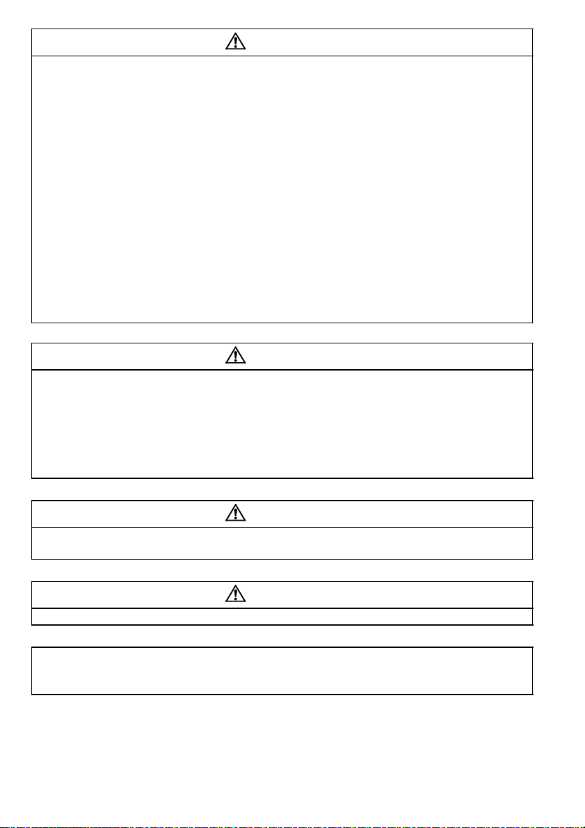
1.1.1 Standard connection diagram
zWith filter pack
*4
*4
*4
*4
Selected
SINK
*2
SOURCE
RS-485
connector
Inverter
*5
RUN
U
V
W
External transistor common
24VDC power supply
PC
Contact input common (source)
Take care not to short
terminals PC-SD.
*5
A
B
*5
*5
C
SE
Alarm output
Running
Open
collector
output
common
FM
Calibration
resistor
SD
Motor
IM
Earth (Ground)
Operation status
output
Open
collector
outputs
Indicator
1mA full-scale
Analog meter
(Digital indicator)
1mA
(+)
*1
3-phase AC
power supply
POINT
MCCB MC
Earth
*6
(Ground)
Jumper: Remove this
jumper to connect
the filter pack.
Control input
signals
(No voltage
input allowed)
Frequency setting signals (Analog)
Frequency setting
potentiometer
1/2W1kΩ
When using current input as the
frequency setting signal, turn the
AU signal on.
Forward rotation start
Reverse rotation start
Multi-speed
selection
Current input selection
Contact input common
*3
Current input(-)
4 to 20mADC(+)
Filter pack
R0
S0
T0
P1
GND
High speed
Middle speed
3
2
1
R
R/L1
S/L2
S
T/L3
T
P/+
P
P1
N/-
STF
STR
RH
RM
AU
SD
10
(+5V)
0 to 5VDC
2
0 to 10VDC
5
(Common)
4
(4 to 20mADC)
(-)
Control circuit terminalMain circuit terminal
REMARKS
*1. Not needed when the setting dial is used for calibration.
Used when calibration must be made near the frequency meter for such a reason as a remote frequency meter.
However, the frequency meter needle may not deflect to full-scale if the calibration resistor is connected.
In this case, use this resistor and setting dial together.
*2. You can switch the position of sink and source logic. Refer to page 26.
*3. When the setting potentiometer is used frequently, use a 2W1kΩ potentiometer.
*4. The terminal functions change with input terminal function selection (Pr. 60 to Pr. 63). (Refer to page 109.)
(RES, RL, RM, RH, RT, AU, STOP, MRS, OH, REX, JOG, X14, X16, (STR) signal selection)
*5. The terminal function changes with the setting of output terminal function selection (Pr. 64, Pr. 65). (Refer to
page 111.) (RUN, SU, OL, FU, RY, Y12, Y13, FDN, FUP, RL, Y95, LF, ABC signal selection)
*6. Connect the GND cable of the filter pack to the earth (ground) terminal of the inverter. Use the earth (ground)
terminal of the filter pack to earth (ground). For inverter earthing (grounding), earth (ground) the inverter
through the filter pack.
CAUTION
To prevent a malfunction due to noise, keep the signal cables more than 10cm away
from the power cables.
2
Page 13
Standard connection diagram and terminal specifications
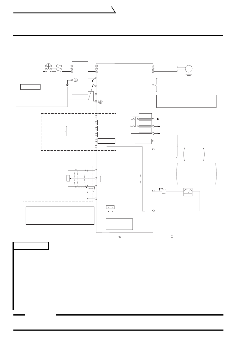
Without filter pack
MCCB
Earth (Ground)
MC
R/L1
S/L2
T/L3
U
V
W
P1
DC reactor
(FR-HEL/BEL: option)
P/+
N/-
1.1.2 Explanation of main circuit terminals
(1) Main circuit
zInverter
Motor
IM
Earth
(Ground)
Jumper: Remove
this jumper when
DC reactor is connected.
Termina l
Symbol
Terminal Name Description
R/L1, S/L2, T/L3 AC power input
U, V, W Inverter output
N/-
P/+, P1
DC voltage
common
Filter pack
connection
Earth (Ground)
Connect the R, S, T cables of the filter pack to these
terminals.
REMARKS
For the inverter without filter pack, connect these to the
commercial power supply.
Connect to a three-phase squirrel-cage motor.
DC voltage common terminal. This is not insulated from
the power and inverter output.
Remove the jumper across terminals P-P1 and connect
the P and P1 cables of the filter pack.
REMARKS
For the inverter without filter pack, remove the jumper
across terminals P-P1 and connect the optional DC
reactor (FR-HEL/BEL).
For earthing (grounding) the inverter chassis.
Connect the GND cable of the filter pack.
REMARKS
Earth (Ground) the inverter without filter pack.
1
WIRING
3
Page 14

Standard connection diagram and terminal specifications
zFilter pack
Termin al
Symbol
R0, S0, T0
Terminal Name Description
Commercial power
supply input
Earth (Ground)
Crimping
Termin al
Terminal Name
Symbol
R, S, T
Inverter power
supply
P, P1 DC reactor terminal
Inverter earth
GND
(ground)
connection
Connect to the commercial power supply.
For earthing (grounding) the filter pack. Must be earthed
(grounded).
Cable
Color
Black Connect to the R, S, T of the inverter.
Red
Green and
yellow
stripes
Remove the jumper across terminals PP1 and connect to the P and P1 terminals
of the inverter.
Connect to the earth (ground) terminal of
the inverter. (Refer to page 2.)
Description
4
Page 15
Standard connection diagram and terminal specifications
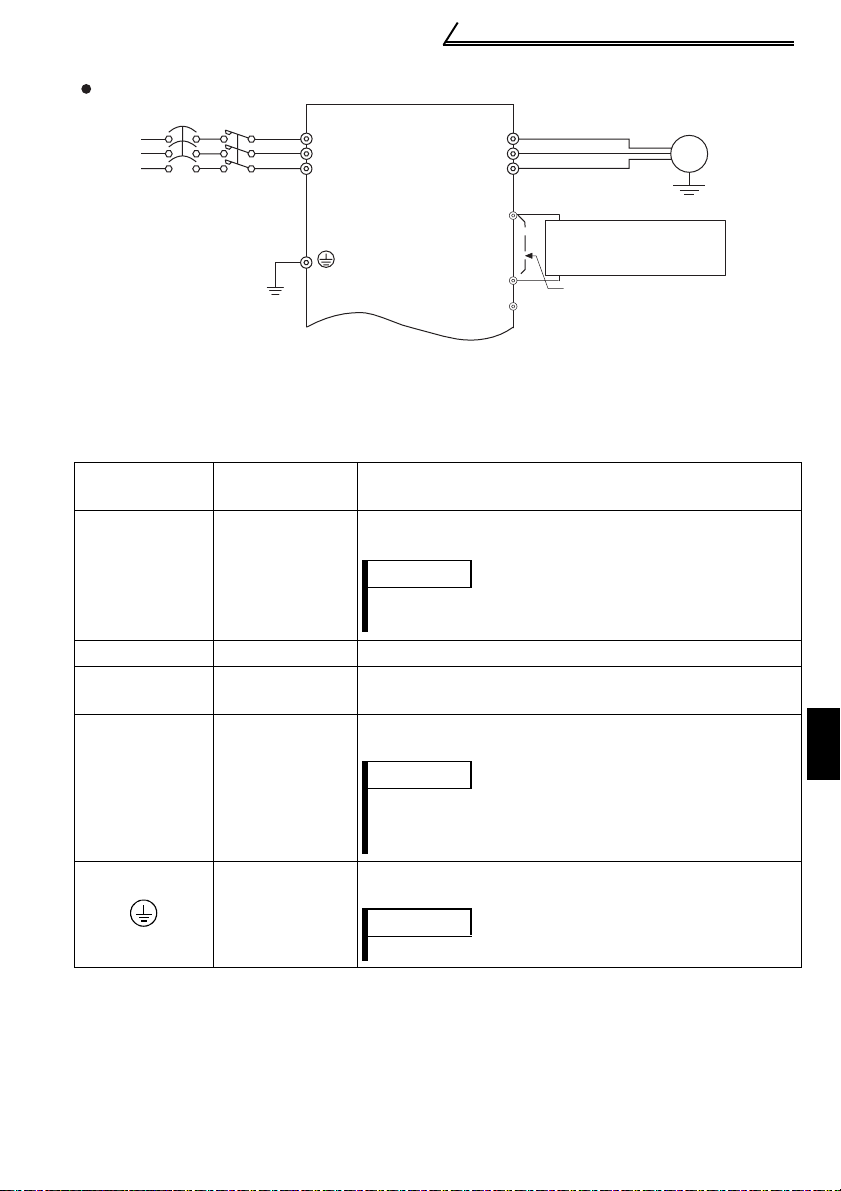
(2) Control circuit
Symbol Terminal Name Definition
Turn on the STF signal to
start forward rotation and
turn it off to stop.
Turn on the STR signal to
start reverse rotation and
turn it off to stop.
Turn on the RH, RM signals in
appropriate combinations to select
multiple speeds.
The priorities of the speed commands
are in order of jog, multi-speed setting
(RH, RM, RL, REX) and AU.
Only when the AU signal is turned on,
the inverter can be operated with the 4
to 20mADC frequency setting signal.
Turning the AU signal on makes voltage
input (across terminals 2-5) invalid.
Common terminal for contact input terminal (sink logic) and
terminal FM.
When connecting the transistor output (open collector
output), such as a programmable controller, when source
logic is selected, connect the external power supply
common for transistor output to this terminal to prevent a
malfunction caused by undesirable currents.
Common output terminal for 24VDC 0.1A power supply (PC
terminal).
Isolated from terminals 5 and SE.
When connecting the transistor output (open collector
output), such as a programmable controller, when sink logic
is selected, connect the external power supply common for
transistor output to this terminal to prevent a malfunction
caused by undesirable currents.
Common terminal for contact input terminal (source logic).
Can be used as 24VDC 0.1A power supply.
5VDC, Permissible load current 10mA.
STF
STR
RHRMMulti-speed
Contact input
AU
SD
(*1, *6)
Input signals
PC
(*1)
10
Forward rotation
start
Reverse rotation
start
selection
Current input
selection
Contact input
common (sink)
(initial setting)
External
transistor
common (source)
24VDC power
supply common
External
transistor
common (sink)
(initial setting)
Contact input
common (source)
24VDC power
supply
Frequency setting
power supply
When the STF and STR
signals are turned on
simultaneously, the stop
command is given.
The terminal
functions change
with input terminal
function selection
(Pr. 60 to Pr.63).
(*3)
1
WIRING
5
Page 16

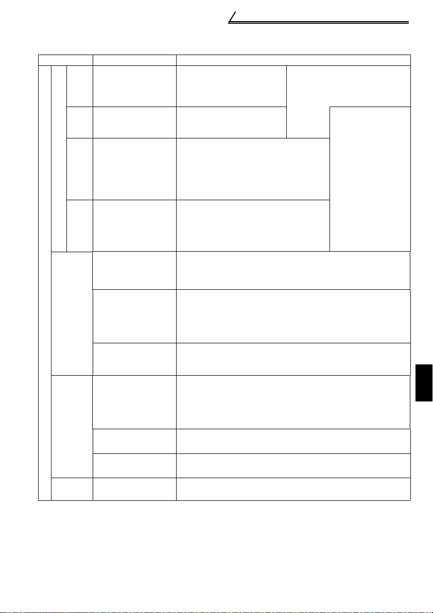
Standard connection diagram and terminal specifications
Symbol Terminal Name Definition
Inputting 0 to 5VDC (or 0 to 10V) provides the maximum output
Frequency setting
2
(voltage signal)
Frequency setting
4
(current signal)
Input signals
Frequency setting
Frequency setting
5
input common
A
BCAlarm output
Inverter
RUN
running
Open collector
Open collector
SE
common
Output signals
FM For meter
Indicator
frequency at 5V (10V) and makes input and output proportional.
Switch between 5V and 10V using Pr. 73 "0-5V, 0-10V selection".
Input resistance 10kΩ. Maximum permissible input voltage 20V
Input 4 to 20mADC. It is factory set at 0Hz for 4mA and at
60Hz for 20mA.
Maximum permissible input current 30mA. Input resistance
approximately 250Ω.
Turn ON signal AU for current input.
Turning the AU signal on makes voltage input invalid. Use any of
Pr. 60 to Pr. 63 (input terminal function selection) to set the AU
signal.
Frequency setting signal (terminal 2, 4) common terminal.
Do not earth (ground).
1 changeover contact output indicates
that the inverter protective function has
activated and the output stopped.
230VAC 0.3A, 30VDC 0.3A. Alarm:
discontinuity across B-C (continuity
across A-C), Normal: continuity across
B-C (discontinuity across A-C).(*5)
Switched low when the inverter output
frequency is equal to or higher than the
starting frequency (factory set to 0.5Hz
variable). Switched high during stop or
DC injection brake operation. (*2)
Permissible load 24VDC 0.1A (a
voltage drop is 3.4V maximum when
the signal is on)
Common terminal for inverter running terminal RUN.
The output signal across terminals FM-SD is factory set to about
1mA at 60Hz and is proportional to the corresponding output
frequency. Since output voltage is pulse waveform, a digital
meter can be connected.
Frequency permissible load current 1mA
Pulse specification 1440 pulses/s at 60Hz
The function of the
terminals changes
according to the
output terminal
function selection
(Pr. 64, Pr.65).
(*4)
(*6)
Using the parameter unit connection cable (FR-CB201 to
——
RS-485
connector
205), the parameter unit (FR-PU04) can be connected.
Communication operation can be performed using RS-485.
For details of RS-485 communication, refer to page 48.
Communication
*1. Do not connect terminals SD and PC each other or to the earth (ground).
For sink logic (factory setting), terminal SD acts as the common terminal of contact input.
For source logic, terminal PC acts as the common terminal of contact input. (Refer to
page 26 for switching method.)
*2. Low indicates that the open collector output transistor is on (conducts). High indicates
that the transistor is off (does not conduct).
*3. RL, RM, RH, RT, AU, STOP, MRS, OH, REX, JOG, RES, X14, X16, (STR) signal
selection (Refer to page 109.)
*4. RUN, SU, OL, FU, RY, Y12, Y13, FDN, FUP, RL, Y95, LF, ABC signal selection (Refer to
page 111.)
*5. To be compliant with the European Directive (Low Voltage Directive), the operating
capacity of relay outputs (A, B, C) should be 30VDC 0.3A.
*6. Terminals SD, SE and 5 are isolated from each other. Do not earth (ground).
Avoid connecting the terminal SD and 5 and the terminal SE and 5.
6
Page 17
1.2 Main circuit terminals
r
y
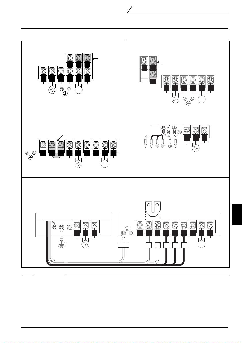
1.2.1 Terminal block layout
zFR-F520J-0.4K, 0.75K
N/- P/+
P1
Jumpe
Main circuit terminals
zFR-F520J-1.5K, 2.2K, 3.7K
z
FR-F540J-0.4K, 0.75K, 1.5K, 2.2K, 3.7K
N/-
Jumper
P/+
R/L1 S/L2 T/L3
Power supply
U V W
IM
Motor
zFilter pack
zFR-F520J-5.5K, 7.5K, 11K, 15K
FR-BFP-(H)0.4K to (H)15K
zFR-F540J-5.5K, 7.5K, 11K, 15K
Jumper
P1
P/+
R/L1 S/L2
N/-
Power supply
T/L3
U V W
IM
Motor
zConnection of the inverter and filter pack
(For details, refer to the instruction manual (basic).)
Filter pack
(FR-BFP)
R0 S0 T0
Earth
(Ground)
Power supply
GND
P1
Power suppl
RST P1PGND
To the inverter
terminal block
Jumper
N/-
P/+
P1
P1 P R S T
R/L1 S/L2 T/L3
Inverter
(FR-F500J)
R/L1 S/L2
T/L3
U V W
IM
Motor
R0 S0 T0
Power
supply
U V W
IM
Motor
1
WIRING
CAUTION
•Make sure the power cables are connected to the R0, S0, T0 of the filter pack (FR-
BFP) (If using the inverter without filter pack, connect to the R, S, T of the
inverter). Never connect the power cable to the U, V, W of the inverter. (Phase
need not be matched)
•Connect the motor to U, V, W. At this time, turning on the forward rotation switch
(signal) rotates the motor in the counterclockwise direction when viewed from the
motor shaft.
•When connecting the filter pack, make sure the jumper across the terminals P1-P
of the inverter is removed.
7
Page 18

Main circuit terminals
1.2.2 Cables, wiring length, and crimping terminals
The following table indicates a selection example for the wiring length of 20m.
<200V class>
2
)
Cable Sizes
AWG
R, S, T
U, V, W
Cable Sizes
AWG
PVC Cable
(mm2)
R, S, T U, V, W
PVC Cable
(mm2)
U, V, W
Ter-
Applicable
Inverter
FR-F520J-0.4K to
0.75K
FR-F520J-1.5K,
2.2K
FR-F520J-3.7K
FR-F520J-5.5K
FR-F520J-7.5K
FR-F520J-11K
FR-F520J-15K
Tight-
minal
ening
Screw
Torque
size
N
M3.5 1.2 2-3.5 2-3.5 2 2 14 14 2.5 2.5
M4 1.5 2-4 2-4 2 2 14 14 2.5 2.5
M4 1.5 5.5-4 5.5-4 3.5 3.5 12 12 4 2.5
M5 2.5 5.5-5 5.5-5 5.5 5.5 10 10 6 6
M5 2.5 14-5 8-5 14 8 6 8 16 10
M5 2.5 14-5 14-5 14 14 6 6 16 16
M6 4.4 22-6 22-6 22 22 4 4 25 25
Crimping
⋅
m
R, S, T U, V, W
Termin al
HIV Cable
(mm
R, S, T
U, V, W
<400V class>
Ter-
Applicable
Inverter
FR-F540J-0.4K to
3.7K
FR-F540J-5.5K
FR-F540J-7.5K
FR-F540J-11K
FR-F540J-15K
Tight-
minal
ening
Screw
Torque
size
N
M4 1.5 2-4 2-4 2 2 14 14 2.5 2.5
M4 1.5 5.5-4 2-4 3.5 2 12 14 4 2.5
M4 1.5 5.5-4 5.5-4 3.5 3.5 12 12 4 4
M4 1.5 5.5-4 5.5-4 5.5 5.5 10 10 6 6
M6 4.4 14-6 8-6 14 8 6 8 16 10
Crimping
Termin al
⋅
m
R, S, T U, V, W R, S, T U, V, W R, S, T U, V, W R, S, T
HIV Cable
(mm2)
*The terminal screw size of the filter pack (FR-BFP) is the same as that of the inverter.
Wiring length
• FR-F540J-0.4K ............................. 50m or less
• FR-F520J-0.4K to 3.7K
FR-F540J-0.75K to 3.7K ............... 100m or less
• FR-F520J-5.5K to 15K
FR-F540J-5.5K to 15K .................. 500m or less
CAUTION
•If the wiring length of the FR-F540J-0.4K or 0.75K is 30m or more, use the
carrier frequency of 1kHz.
•When automatic torque boost is selected in Pr. 98 "automatic torque boost
selection (motor capacity)", the wiring length must be 30m maximum. (Refer
to page 133.)
•If the wiring distance between the inverter and motor is long, the motor torque
will decrease due to the voltage drop of the main circuit cable (especially at
low-frequency output).
Use thick cables so that a voltage drop is 2% or less.
8
Page 19

Main circuit terminals
1.2.3 Wiring instructions
1) Use crimping terminals with insulation sleeve to wire the power supply and motor.
2) Application of power to the output terminals (U, V, W) of the inverter will damage the
inverter. Never perform such wiring.
3) After wiring, wire offcuts must not be left in the inverter (filter pack).
Wire offcuts can cause an alarm, failure or malfunction. Always keep the inverter
clean.
When drilling mounting holes in an enclosure etc., take care not to allow chips and
other foreign matter to enter the inverter.
4) Use cables of the recommended size to make a voltage drop 2% maximum.
If the wiring distance is long between the inverter and motor, a main circuit cable
voltage drop will cause the motor torque to decrease especially at the output of a
low frequency.
5) For long distance wiring, the high response current limit function may be reduced or
the devices connected to the secondary side may malfunction or become faulty
under the influence of a charging current due to the stray capacity of wiring.
Therefore, note the maximum overall wiring length.
6) Electromagnetic wave interference
The input/output (main circuit) of the inverter includes high frequency components,
which may interfere with the communication devices (such as AM radios) used near
the inverter. When using the inverter without the filter pack, install a FR-BIF(-H)
optional radio noise filter (for use on the input side only) or FR-BSF01 or FR-BLF
line noise filter to minimize interference.
7) Do not install a power capacitor, surge suppressor or radio noise filter (FR-BIF(-H)
option) on the output side of the inverter.
This will cause the inverter to trip or the capacitor and surge suppressor to be
damaged. If any of the above devices are connected, remove them.
8) Before starting wiring or other work after the inverter is operated, wait for at least 10
minutes after the power supply has been switched off, and check that there are no
residual voltage using a tester or the like. The capacitor is charged with high
voltage for some time after power off and it is dangerous.
9
1
WIRING
Page 20
Main circuit terminals
1.2.4 Selection of peripheral devices
Check the inverter type of the inverter you purchased. Appropriate peripheral devices
must be selected according to the capacity.
Refer to the following list and prepare appropriate peripheral devices:
<200V class>
Moulded Case Circuit Breaker
Motor
Output
Inverter Type
Earth Leakage Circuit Breaker (ELB)
(kW)
With filter pack Without filter pack
0.4 FR-F520J-0.4K
0.75 FR-F520J-0.75K
1.5 FR-F520J-1.5K 30AF/15A 30AF/15A S-N10
2.2 FR-F520J-2.2K
3.7 FR-F520J-3.7K
5.5 FR-F520J-5.5K 50AF/40A 50AF/50A S-N25
7.5 FR-F520J-7.5K
11 FR-F520J-11K
15 FR-F520J-15K 100AF/100A 225AF/125A S-N65
<400V class>
Motor
Output
Inverter Type
Earth Leakage Circuit Breaker (ELB)(*2,
(kW)
With filter pack Without filter pack
0.4 FR-F540J-0.4K
0.75 FR-F540J-0.75K
1.5 FR-F540J-1.5K 30AF/10A 30AF/10A S-N10
2.2 FR-F540J-2.2K
3.7 FR-F540J-3.7K
5.5 FR-F540J-5.5K 30AF/20A 30AF/30A S-N20, S-N21
7.5 FR-F540J-7.5K
11 FR-F540J-11K
15 FR-F540J-15K 50AF/50A 100AF/60A S-N35
(MCCB)(*1, *3) or
Magnetic
Contactor
(*2, *3)
30AF/5A 30AF/5A S-N10
30AF/10A 30AF/10A S-N10
30AF/15A 30AF/20A S-N10
30AF/30A 30AF/30A S-N20,S-N21
50AF/50A 100AF/60A S-N35
100AF/75A 100AF/75A S-N50
(MC)
Moulded Case Circuit Breaker
(MCCB)(*1, *3) or
Magnetic
Contactor
*3)
30AF/5A 30AF/5A S-N10
30AF/5A 30AF/5A S-N10
30AF/10A 30AF/15A S-N10
30AF/15A 30AF/20A S-N20, S-N21
30AF/30A 30AF/30A S-N20, S-N21
50AF/40A 50AF/50A S-N25
(MC)
• Select the MCCB according to the power supply
*1.
capacity.
• Install one MCCB per inverter.
MCCB
MCCB
INV
INV
IM
IM
*2. For installations in the United States or Canada, the
circuit breaker must be inverse time or instantaneous trip type.
*3. When the breaker on the inverter primary side trips, check for the wiring fault (short
circuit), damage to internal parts of the inverter, etc.
Identify the cause of the trip, then remove the cause and power on the breaker.
10
Page 21
Main circuit terminals
1.2.5 Leakage current and installation of earth (ground) leakage circuit breaker
Due to static capacitances existing in the inverter I/O wiring and motor, leakage
currents flow through them. Since their values depend on the static capacitances,
carrier frequency, etc., take the following countermeasures.
(1) To-earth (ground) leakage currents
Leakage currents may flow not only into the inverter's own line but also into the
other line through the earth (ground) cable, etc.
These leakage currents may operate earth (ground) leakage circuit breakers and
earth (ground) leakage relays unnecessarily.
Countermeasures
• If the carrier frequency setting is high, decrease the carrier frequency (Pr. 72) of the
inverter.
Note that motor noise increases. Selection of Soft-PWM control (Pr. 70) will make it
unoffending. (Factory setting)
• By using earth leakage circuit breakers designed for harmonic and surge
suppression in the inverter's own line and other line, operation can be performed
with the carrier frequency kept high (with low noise).
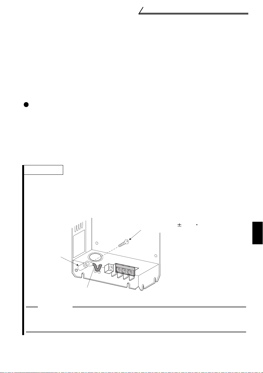
REMARKS
When the filter pack is provided, leakage current can be reduced by removing the earth (ground)
cable for the capacitive filter and securing it with the supplied screw for leakage current
countermeasure (plastic) and spacer (plastic). However, the noise reduction effect of the
capacitive filter is lost.
(Pull out the earth (ground) cable for the capacitive filter a little to wire.)
<Mounting method>
Filter pack
Screw for leakage current countermeasure (plastic)
(Tightening torque is 0.35 0.05N m)
1
Spacer
(plastic)
Earth (Ground) cable for capacitive filter
CAUTION
If the earth (ground) cable for the capacitive filter is removed, it is charged
while power is on or shortly after power off. Do not touch the earth (ground)
cable as you may get an electric shock.
11
WIRING
Page 22
Main circuit terminals
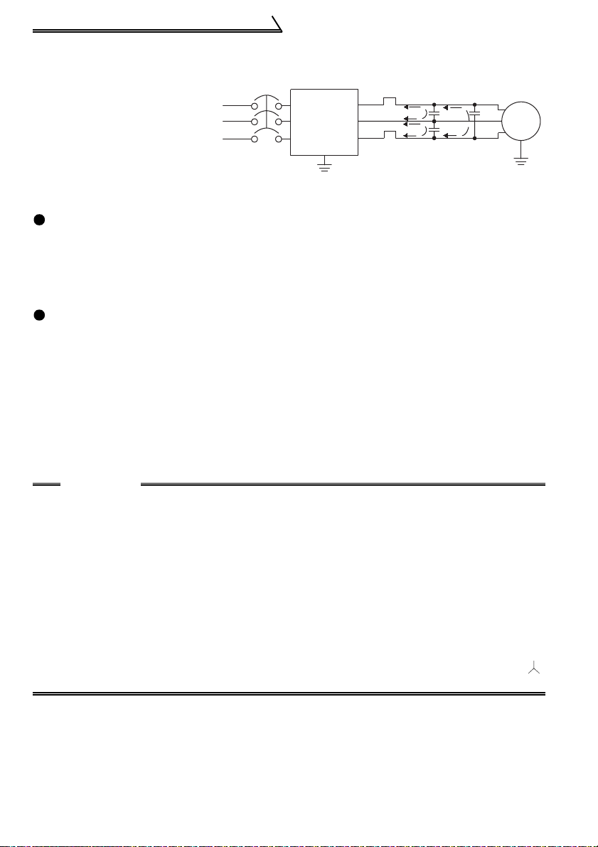
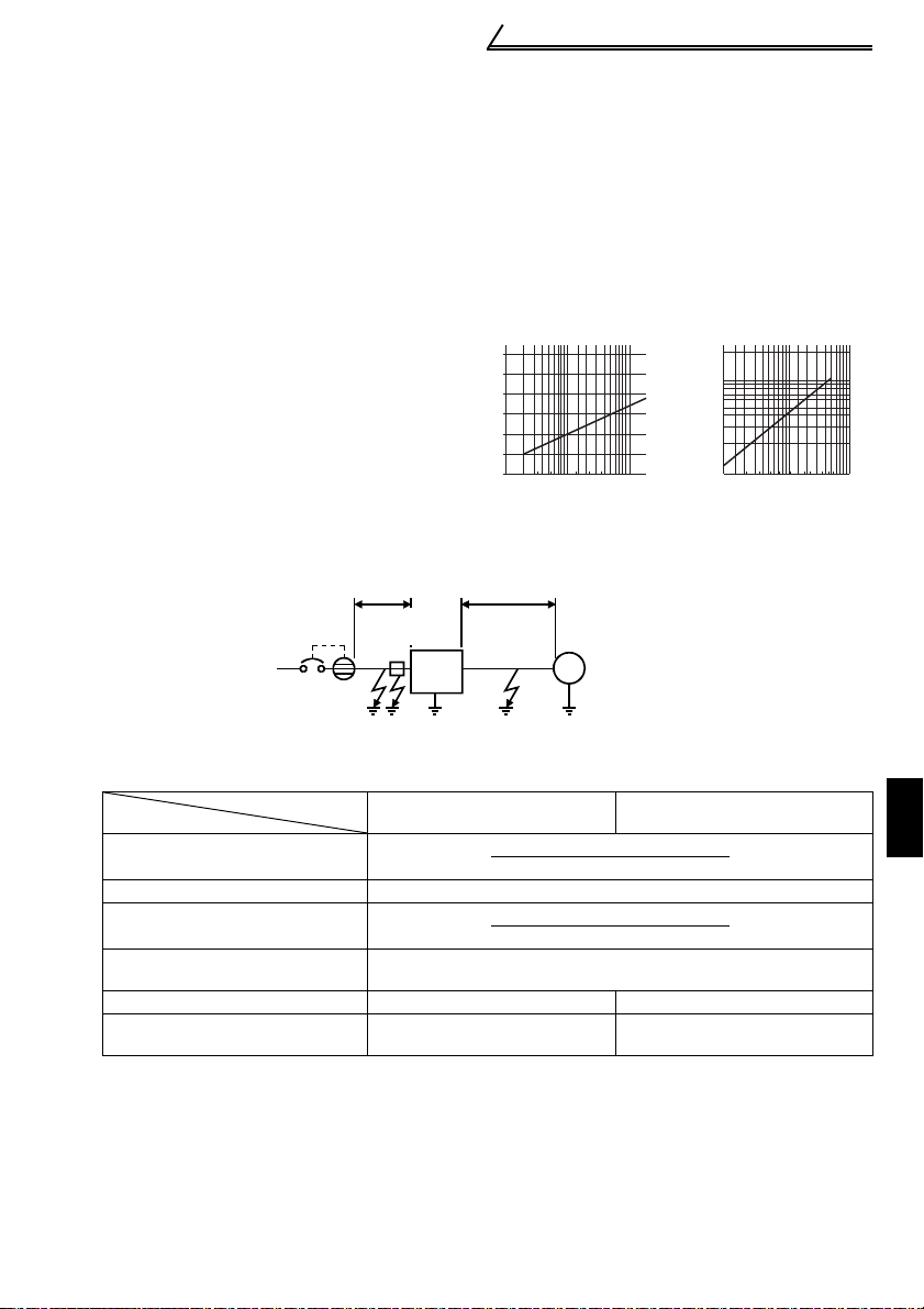
(2) Line-to-line leakage currents
Harmonics of
leakage currents
flowing in static
capacities between
Power
supply
MCCB
Inverter
the inverter output
cables may operate
the external thermal
Line-to-Line Leakage Current Path
relay unnecessarily.
Countermeasures
• Use the electronic thermal relay function of the inverter.
• Decrease the carrier frequency. Note that motor noise increases. Selection of
Soft-PWM (Pr. 70) makes it unoffending.
To ensure that the motor is protected against line-to-line leakage currents, it is
recommended to use a temperature sensor to directly detect motor temperature.
Installation and selection of moulded case circuit breaker
Install a moulded case circuit breaker (MCCB) on the power receiving side to
protect the wiring of the inverter primary side. Select the MCCB according to the
power supply side power factor (which depends on the power supply voltage, output
frequency and load). Especially for a completely electromagnetic MCCB, one of a
slightly large capacity must be selected since its operation characteristic varies with
harmonic currents. (Check it in the data of the corresponding breaker.) As an earth
(ground) leakage breaker, use the Mitsubishi earth (ground) leakage breaker
designed for harmonics and surge suppression. (Refer to page 10 for the
recommended models.)
Thermal relay
Line static
capacitances
Motor
IM
CAUTION
•Select the MCCB according to the inverter power supply capacity.
•Install one MCCB per inverter.
•The inverter has a protective function based on electronic overcurrent protection
(electronic thermal relay function) to protect the motor from overheating.
However, when running multiple motors with one inverter or operating a multipole motor, provide a thermal relay (OCR) between the inverter and motor. In this
case, set the electronic thermal relay function (electronic overcurrent protection)
of the inverter to 0A. And set the electronic overcurrent relay, add the line-to-line
leakage current to 1.0 times the current value at 50 Hz on the motor rating plate or
to 1.1 times the current value at 60 Hz.
•When the FR-BFP (filter pack) is used, leakage current is 4mA.(8mA for 400V
class.) (equivalent to one-phase of cable for the three-phase three wire
connection)
12
Page 23
Main circuit terminals
)
(3) Selecting the rated sensitivity current for the earth leakage circuit
breaker
When using the earth leakage circuit breaker with the inverter circuit, select its rated
sensitivity current as follows, independently of the PWM carrier frequency:
• Breaker for harmonic and surge
Rated sensitivity current:
I
∆n ≥ 10 × (lg1+Ign+lg2+lgm)
• Standard breaker
Rated sensitivity current:
I
∆n ≥ 10 × {lg1+lgn+3 × (lg2+lgm)}
lg1, lg2 : Leakage currents of cable
path during commercial
power supply operation
lgn : Leakage current of noise
filter on inverter input side
lgm : Leakage current of motor
during commercial power
supply operation
<Example>
22
2mm ×5m
NV
Filter
pack
Example of leakage
current per 1km in cable
path during commercial
power supply operation
when the CV cable is
routed in metal conduit
(200V 60Hz)
120
100
80
60
40
20
0
2 3.5 8 142238 80
Leakage current (mA)
Cable size (mm)
2mm ×70m
Inverter
5.5 3060100
φ
3 200V
IM
1.5kW
Leakage current
example of three-phase
induction motor
during commercial
power supply
operation
(200V 60Hz)
2.0
1.0
0.7
0.5
0.3
0.2
150
2
0.1
Leakage current (mA)
Motor capacity (kW
1.5 3 .7
2.2
7.5 152 21137
5.5 18.5
55
45
30
Ig1 Ign Ig2 Igm
Leakage current (Ig1) (mA)
Breaker for Harmonic and
Surge
20 ×
1000m
5m
Standard Breaker
= 0.10
Leakage current (Ign) (mA) 0 (without filter pack)
Leakage current (Ig2) (mA)
Motor leakage
current (Igm) (mA)
20 ×
70m
1000m
0.16
= 1.40
Total leakage current (mA) 1.66 4.78
Rated sensitivity current
(mA) (≥ Ig
× 10)
30 100
13
1
WIRING
Page 24

Main circuit terminals
CAUTION
•The earth (ground) leakage circuit breaker should be installed to the primary
(power supply) side of the inverter.
•In the connection neutral point earth (grounded) system, the sensitivity
current becomes worse for earth (ground) faults on the inverter secondary
side. Earthing (Grounding) must conform to the requirements of national and
local safety regulations and electrical codes. (NEC section 250, IEC 536 class
1 and other applicable standards)
•When the breaker is installed on the secondary side of the inverter, it may be
unnecessarily operated by harmonics if the effective value is less than the
rating. In this case, do not install the breaker since the eddy current and
hysteresis loss increase and the temperature rises.
•General products indicate the following models: BV-C1, BC-V, NVB, NV-L, NVG2N, NV-G3NA, NV-2F, earth (ground) leakage relay (except NV-ZHA), NV with
AA neutral wire open-phase protection
The other models are designed for harmonic and surge suppression: NV-C/
NV-S/MN series, NV30-FA, NV50-FA, BV-C2, earth (ground) leakage alarm
breaker (NF-Z), NV-ZHA, NV-H
14
Page 25
Main circuit terminals
r
1.2.6 Power-off and magnetic contactor (MC)
(1) Inverter input side magnetic contactor (MC)
On the inverter's input side, it is recommended to provide an MC for the following
purposes. (Refer to page 10 for selection)
1) To release the inverter from the power supply when the inverter protective function
is activated or the drive becomes faulty (e.g. emergency stop operation)
2) To prevent any accident due to an automatic restart at restoration of power after an
inverter stop made by a power failure
3) To rest the inverter for an extended period of time
The control power supply for inverter is always running and consumes a little power.
When stopping the inverter for an extended period of time, powering off the inverter
will save power slightly.
4) To separate the inverter from the power supply to ensure safe maintenance and
inspection work
The inverter's input side MC is used for the above purpose, select class JEM1038AC3 for the inverter input side current when making an emergency stop during
normal operation.
REMARKS
The MC may be switched on/off to start/stop the inverter. However, since repeated inrush
currents at power on will shorten the life of the converter circuit (switching life is about 100,000
times), frequent starts and stops must be avoided. Turn on/off the inverter start controlling
terminals (STF, STR) to run/stop the inverter.
As shown on the right,
always use the start signal
(ON or OFF across
terminals STF or STR-SD)
Power
supply
to make a start or stop.
(Refer to page 28)
*1. When the power supply
is 400V class, install a
step-down transformer.
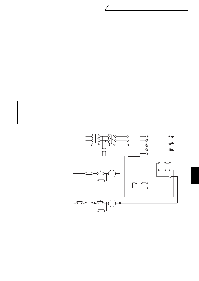
(2) Handling of output side magnetic contactor
In principle, do not provide a magnetic contactor between the inverter and motor and
switch it from off to on during operation. If it is switched on during inverter operation, a
large inrush current may flow, stopping the inverter due to overcurrent shut-off. When
an MC is provided for switching to the commercial power supply, for example, switch it
on/off after the inverter and motor have stopped.
MCCB
Operation ready
ON
OFF
MC
Start/Stop
OFF
Operation
RA
MC
Inverter Start/Stop Circuit Example
MC
R0
S0
T0
T (*1)
MC
RA
(with filter pack)
R
S
T
P1
P
RA
R
S
T
P1
P
Inverter
STF(STR)
SD
W
U
To
V
moto
A
B
C
1
WIRING
15
Page 26
Main circuit terminals
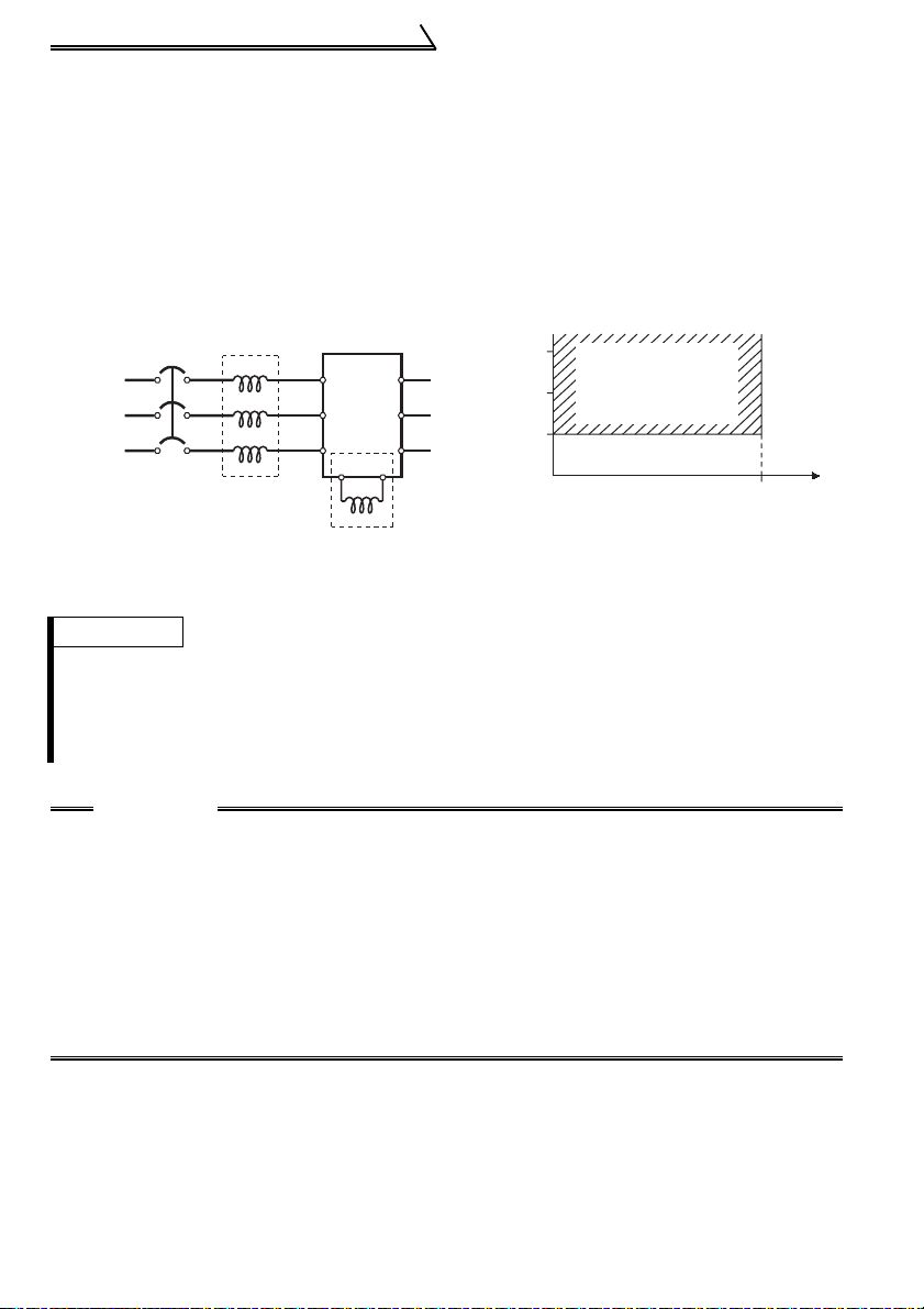
1.2.7 Regarding the installation of the reactor
When the inverter is installed near a large-capacity power transformer (500kVA or
more with the wiring length of 10m (32.81feet) or less) or the power capacitor is to be
switched, an excessive peak current will flow in the power supply input circuit,
damaging the converter circuit. In such a case, always install the reactor (FR-HEL(-H)
/FR-BEL(-H) or FR-HAL(-H)/FR-BAL(-H)). Since the filter pack includes a power factor
improving DC reactor, a reactor need not be installed separately.
Power
supply
MCCB
FR-HAL(-H)/
FR-BAL(-H)
R
S
TZ
Inverter
X
R
Y
S
T
P
FR-HEL(-H)/
FR-BEL(-H)(*)
P1
W
1500
U
V
1000
Power supply equipment
capacity (kVA)
Reactor installation
range
500
010
Wiring length (m)
REMARKS
*When connecting the FR-HEL(-H)/FR-BEL(-H) (filter pack), remove the jumper across
terminals P-P1.
The wiring length between the FR-HEL(-H)/FR-BEL(-H) and the inverter should be 5m
maximum and as short as possible.
Use the cables which are equal in size to those of the main circuit. (Refer to page 8)
CAUTION
•The power factor improving capacitor and surge suppressor on the inverter
output side may be overheated or damaged by the high frequency
components of the inverter output. Also, since an excessive current flows in
the inverter to activate overcurrent protection, do not install a capacitor or
surge suppressor. Use a power factor improving reactor for power factor
improvement.
•If a surge voltage occurs in the power supply system, this surge energy may
flow into the inverter, causing the inverter to display OV1, OV2 or OV3 and
come to an alarm stop. In such a case, also install the optional FR-HEL(-H)/FRBEL(-H) or FR-HAL(-H)/FR-BAL(-H) power factor improving reactor.
16
Page 27
Main circuit terminals
1.2.8
Regarding noise (EMI) and the installation of a noise filter
Some noise enters the inverter causing it to malfunction and others are generated by
the inverter causing the malfunction of peripheral devices. Though the inverter is
designed to have high immunity performance, it handles low-level signals, so it
requires the following general countermeasures to be taken.
(1) General countermeasures
• Do not run the power cables (I/O cables) and signal cables of the inverter in parallel
with each other and do not bundle them.
• Use twisted shield cables for the detector connecting and control signal cables and
connect the sheathes of the shield cables to terminal SD.
• Earth (Ground) the inverter, motor, etc. at one point.
• Capacitances exist between the inverter's I/O wiring, other cables, earth (ground)
and motor, through which leakage currents flow to cause the earth leakage circuit
breaker, earth (ground) leakage relay and external thermal relay to operate
unnecessarily. To prevent this, take appropriate measures, e.g. set the carrier
frequency in Pr. 72 to a low value, use an earth (ground) leakage circuit breaker
designed for suppression of harmonics and surges, and use the electronic thermal
relay function built in the inverter.
• The input and output of the inverter main circuit include high-degree harmonics,
which may disturb communication devices (AM radios) and sensors used near the
inverter.
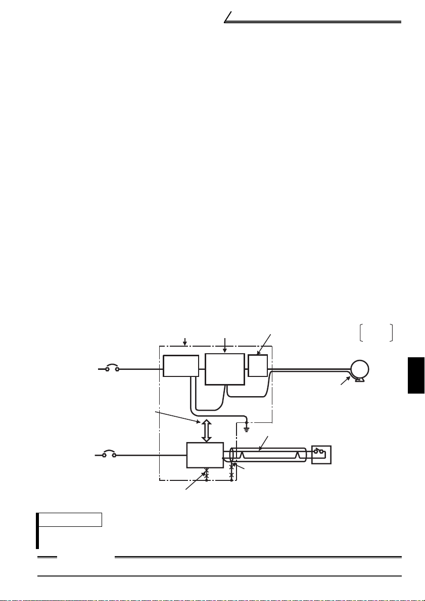
<Noise (EMI) reduction examples>
Inverter
power supply
Separate inverter and power
line by more than 30cm
and at least 10cm
from sensor circuit.
Control
power supply
Do not earth (ground)
enclosure directly.
Do not earth (ground)
control cable.
Enclosure
Filter
pack
Power
supply
for sensor
Reduce carrier
frequency.
Inverter
FRBLF
Do not earth (ground) shield but connect
it to signal common cable.
Install a line noise filter
on inverter's output side.
Use 4-core cable for motor
power cable and use one
cable as earth (ground) cable.
Use twisted pair shielded cable.
Sensor
FR-BLF
FR-BSF01
IM
Motor
1
WIRING
REMARKS
For the inverter without filter pack, install a line noise filter (FR-BLF, FR-BSF01) or radio noise
filter (FR-BIF) on the inverter input side as a noise reduction measure.
CAUTION
For compliance with the EU, EMC directive, please refer the instruction manual (basic).
17
Page 28
Main circuit terminals
1.2.9 Earthing (Grounding) precautions
z Leakage currents flow in the inverter (filter pack). To prevent an electric shock, the
inverter (filter pack) and motor must be earthed (grounded). Earthing (Grounding)
must conform to the requirements of national and local safety regulations and
electrical codes.
(NEC section 250, IEC 536 class 1 and other applicable standards)
z Use the dedicated earth (ground) terminal to earth (ground) the inverter (filter pack).
(Do not use the screw in the casing, chassis, etc.)
Use a tinned* crimping terminal to connect the earth (ground) cable. When
tightening the screw, be careful not to damage the threads.
*Plating should not include zinc.
z Use the thickest possible earth (ground) cable. Use the cable whose size is equal to
or greater than that indicated in the following table, and minimize the cable length.
The earthing (grounding) point should be as near as possible to the inverter.
2
Motor Capacity
2.2kW or less 2 (2.5) 2 (2.5)
3.7kW 3.5 (4) 2 (4)
5.5kW 5.5 (6) 3.5 (4)
7.5kW 14 (16) 3.5 (4)
11kW 14 (16) 5.5 (6)
15kW 22 (25) 14 (16)
Earth (Ground) Cable Size (Unit: mm
200V class 400V class
For use as a product compliant with the Low Voltage Directive, use PVC cable
whose size is indicated within parentheses.
)
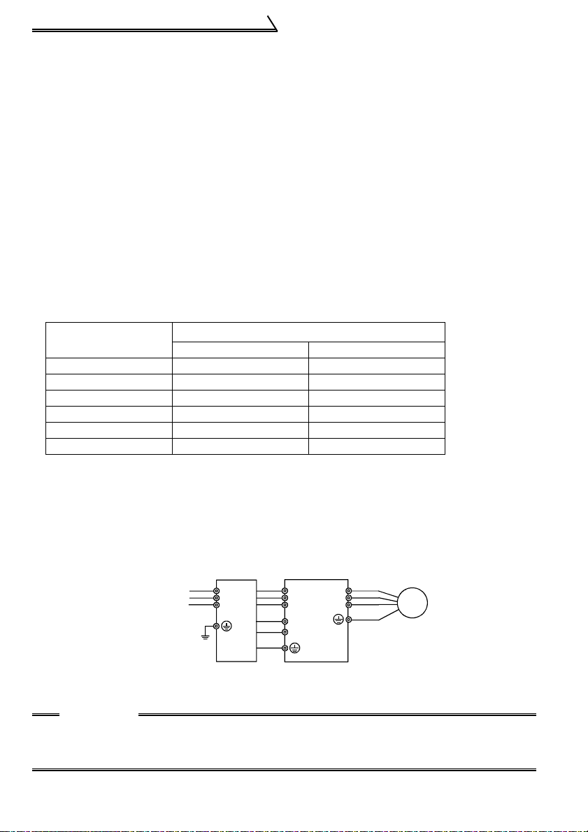
z As a noise reduction technique, use one wire of the four-core cable with the earth
(ground) terminal of the motor, and earth (ground) at one point from the filter pack
side via the inverter. (Refer to page 2.)
Inverter
R
S
T
P1
P
W
U
V
Motor
IM
Power
supply
Earthing
(Grounding)
Filter pack
R
R0
S
S0
T
T0
P1
P
GND
(For the type without filter pack, earth (ground) the motor with the inverter at one point
on the inverter side.)
CAUTION
When the inverter is run in the low acoustic noise mode, more leakage currents
occur than in the non-low acoustic noise mode due to high-speed switching
operation. Always earth (ground) the inverter, motor and filter pack before use.
18
Page 29
Main circuit terminals
1.2.10 Power supply harmonics
The inverter may generate power supply harmonics from its converter circuit to affect
the power generator, power capacitor etc. Power supply harmonics are different from
noise and leakage currents in source, frequency band and transmission path. Take the
following countermeasure suppression techniques.
The following table indicates differences between harmonics and noise:
Item Harmonics Noise
Frequency
Environment To-electric channel, power impedance To-space, distance, wiring path
Quantitative
understanding
Generated amount Nearly proportional to load capacity
Affected equipment
immunity
Suppression example Provide reactor.* Increase distance.
*The filter pack (FR-BFP) produces the same effect as when the DC reactor (FR-
HEL(-H)/FR-BEL(-H)) is connected.
Suppression technique
Harmonic currents produced
on the power supply side by
the inverter change with such
conditions as whether there
are wiring impedances and a
DC reactor (FR-HEL(-H)/FRBEL(-H) or FR-HAL(-H)/FRBAL(-H)) and the magnitudes
of output frequency and
output current on the load
side.
For the output frequency and output current, we understand that they should be
calculated in the conditions under the rated load at the maximum operating frequency.
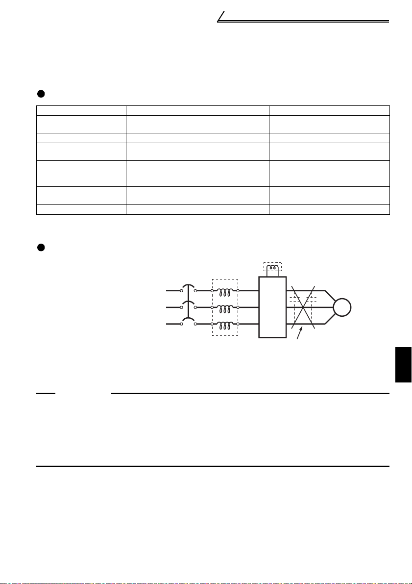
CAUTION
The power factor improving capacitor and surge suppressor on the inverter
output side may be overheated or damaged by the high frequency components
of the inverter output. Also, since an excessive current flows in the inverter to
activate overcurrent protection, do not provide a capacitor and surge
suppressor on the inverter output side when the motor is driven by the inverter.
To improve the power factor, insert a reactor on the inverter's primary side or
DC circuit. For full information, refer to page 16.
Normally 40th to 50th degrees or less
(up to 3kHz or less)
Theoretical calculation possible
Specified in standard per equipment
FR-HEL(-H)
/FR-BEL(-H)
MCCB
FR-HAL(-H)
/FR-BAL(-H)
High frequency (several 10kHz
to 1GHz order)
Random occurrence,
quantitative grasping difficult
Change with current variation
ratio (larger as switching speed
increases)
Different depending on maker's
equipment specifications
Motor
IM
Inverter
Do not provide power factor
improving capacitor.
1
WIRING
19
Page 30
Main circuit terminals
1.2.11 Harmonic suppression guideline
Harmonic currents flow from the inverter to a power receiving point via a power
transformer. The harmonic suppression guideline was established to protect other
consumers from these outgoing harmonic current.
The three-phase 200V input specifications 3.7kW or less are previously covered by
"Harmonic suppression guideline for household appliances and general-purpose
products" and other models are covered by "Harmonic suppression guideline for
consumers who receive high voltage or special high voltage". However, the generalpurpose inverter has been excluded from the target products covered by "Harmonic
suppression guideline for household appliances and general-purpose products" in
January 2004. Later, this guideline was repealed on September 6, 2004. All capacities
of all models are now target products of "Harmonic suppression guideline for
consumers who receive high voltage or special high voltage" (hereinafter referred to
as "Guideline for specific consumers").
"Guideline for specific consumers"
This guideline sets forth the maximum values of harmonic currents outgoing from a
high-voltage or especially high-voltage consumer who will install, add or renew
harmonic generating equipment. If any of the maximum values is exceeded, this
guideline requires that consumer to take certain suppression measures.
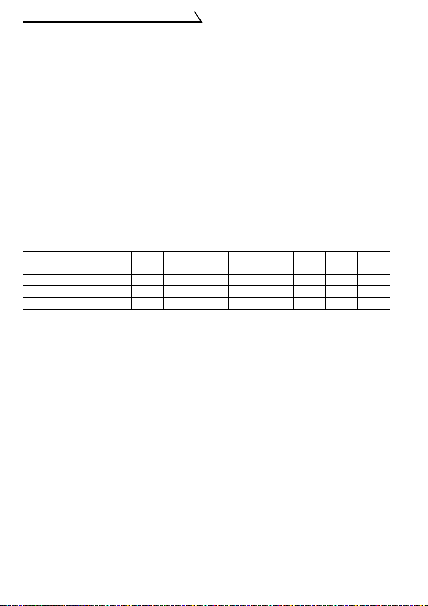
Table 1 Maximum Values of Outgoing Harmonic Currents per 1kW Contract Power
Received Power Voltage 5th 7th 11th 13th 17th 19th 23rd
6.6 kV 3.5 2.5 1.6 1.3 1.0 0.9 0.76 0.70
22 kV 1.8 1.3 0.82 0.69 0.53 0.47 0.39 0.36
33 kV 1.2 0.86 0.55 0.46 0.35 0.32 0.26 0.24
Over
23rd
20
Page 31

(1)
Application of the guideline for specific consumers
New installation/addition/
renewal of equipment
Calculation of equivalent
capacity sum
Not more than
reference capacity
Sum of equivalent
capacities
Over reference
capacity
Calculation of outgoing
harmonic current
Main circuit terminals
Is outgoing harmonic
current equal to or lower
than maximum value?
Not more than
maximum value
Harmonic suppression
technique is not required.
Over maximum value
Harmonic suppression
technique is required.
Table 2 Conversion Factors for FR-F500J Series
Class Circuit Type Conversion Factor (Ki)
Without reactor K31 = 3.4
Three-phase bridge
3
(Capacitorsmoothed)
With reactor (AC side) K32 = 1.8
With reactor (DC side) or filter pack K33 = 1.8
With reactors (AC, DC sides) K34 = 1.4
Table 3 Equivalent Capacity Limits
Received Power Voltage Reference Capacity
6.6kV 50 kVA
22/33 kV 300 kVA
66kV or more 2000 kVA
1
WIRING
21
Page 32

Main circuit terminals
Table 4 Harmonic Contents (Values of the fundamental current of 100%)
Reactor 5th 7th 11th 13th 17th 19th 23rd 25th
Not used 65 41 8.5 7.7 4.3 3.1 2.6 1.8
Used (AC side) 38 14.5 7.4 3.4 3.2 1.9 1.7 1.3
Used (DC side)
or with filter
pack
Used (AC, DC
sides)
30 13 8.4 5.0 4.7 3.2 3.0 2.2
28 9.1 7.2 4.1 3.2 2.4 1.6 1.4
1) Calculation of equivalent capacity (P0) of harmonic generating equipment
The "equivalent capacity" is the capacity of a 6-pulse converter converted from the
capacity of consumer's harmonic generating equipment and is calculated with the
following equation. If the sum of equivalent capacities is higher than the limit in
Table 3, harmonics must be calculated with the following procedure:
P0=Σ (Ki × Pi) [kVA]
Ki: Conversion factor (refer to Table 2)
Pi: Rated capacity of harmonic
generating equipment* [kVA]
i: Number indicating the conversion
circuit type
* Rated capacity: Determined by the
capacity of the applied motor and
found in Table 5. It should be noted
that the rated capacity used here is
used to calculate a generated
harmonic amount and is different
from the power supply capacity
required for actual inverter drive.
2) Calculation of outgoing harmonic current
Outgoing harmonic current = fundamental wave current (value converted from
received power voltage) × operation ratio × harmonic
content
• Operation ratio: Operation ratio = actual load factor × operation time ratio during
30 minutes
• Harmonic content: Found in Table 4.
22
Page 33

Main circuit terminals
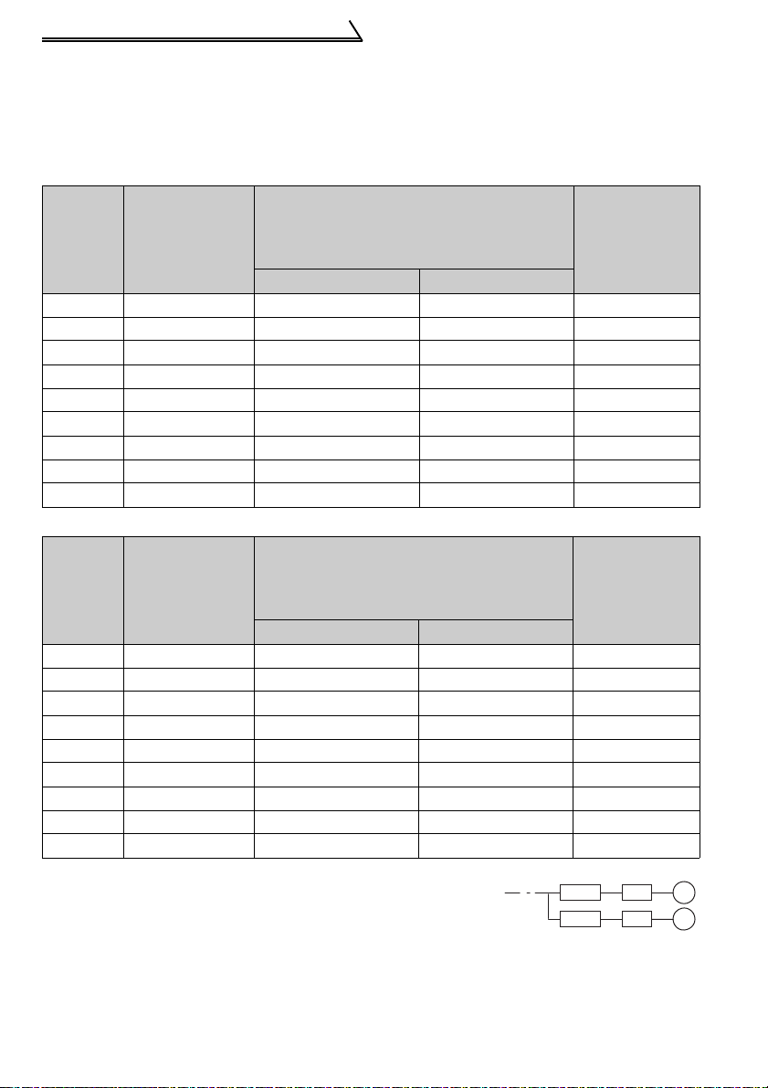
Table 5 Rated Capacities and Outgoing Harmonic Currents for Inverter Drive
(with filter pack)
Rated
Applied
Motor
(kW)
0.75 1.37 83 0.97 24.9 10.76 6.97 4.15 3.90 2.66 2.49 1.83
Current
[A]
400V 5th 7th 11th 13th 17th 19th 23rd 25th
0.4 0.81 49 0.57 14.7 6.37 4.12 2.45 2.30 1.57 1.47 1.08
1.5 2.75 167 1.95 50.10 21.71 14.03 8.35 7.85 5.34 5.01 3.67
2.2 3.96 240 2.81 72.00 31.20 20.16 12.00 11.28 7.68 7.20 5.28
3.7 6.50 394 4.61 118.2 51.2 33.10 19.70 18.52 12.61 11.82 8.67
5.5 9.55 579 6.77 173.7 75.27 48.64 28.95 27.21 18.53 17.37 12.74
7.5 12.8 776 9.07 232.8 100.9 65.18 38.80 36.47 24.83 23.28 17.07
11 18.5 1121 13.1 336.3 145.7 94.16 56.05 52.69 35.87 33.63 24.66
15 24.9 1509 17.6 452.7 196.2 126.8 75.45 70.92 48.29 45.27 33.20
6.6kV
Equivalent of
Fundamental
Wave
Current (mA)
Rated
Capacity
(kVA)
Outgoing Harmonic Current Converted from 6.6kV
(with filter pack, 100% operation ratio)
3) Harmonic suppression technique requirement
If the outgoing harmonic current is higher than; maximum value per 1kW (contract
power) × contract power, a harmonic suppression technique is required.
4) Harmonic suppression techniques
No. Item Description
Reactor installation
(ACL, DCL)
1
Installation of power
2
factor improving
capacitor
Transformer multiphase operation
3
Passive
4
(AC filter)
Active filter This filter detects the current of a circuit generating a harmonic
5
Install a reactor (ACL) in the AC side of the inverter or a reactor
(DCL) in its DC side or both to suppress outgoing harmonic
currents. (The DC reactor has already been installed in the type
with filter pack.)
When used with a series reactor, the power factor improving
capacitor has an effect of absorbing harmonic currents.
Use two transformers with a phase angle difference of 30
° as in -
∆, ∆-∆ combination to provide an effect corresponding to 12 pulses,
reducing low-degree harmonic currents.
A capacitor and a reactor are used together to reduce impedances
at specific frequencies, producing a great effect of absorbing
harmonic currents.
current and generates a harmonic current equivalent to a difference
between that current and a fundamental wave current to suppress
a harmonic current at a detection point, providing a great effect of
absorbing harmonic currents.
1
WIRING
23
Page 34

Main circuit terminals
1.2.12 Inverter-driven 400V class motor
In the PWM type inverter, a surge voltage attributable to wiring constants is generated
at the motor terminals. Especially for a 400V class motor, the surge voltage may
deteriorate the insulation. When the 400V class motor is driven by the inverter,
consider the following measures:
•Measures
It is recommended to take either of the following measures:
(1) Rectifying the motor insulation
For the 400V class motor, use an insulation-enhanced motor. Specifically
1) Specify the "400V class inverter-driven, insulation-enhanced motor".
2) For the dedicated motor such as the constant-torque motor and low-vibration
motor, use the "inverter-driven, dedicated motor".
CAUTION
When the wiring length between the motor and inverter is 40m or more, take
the above countermeasure and also set the long wiring mode in Pr. 70 "SoftPWM setting". (Refer to page 114 for Pr. 70.)
(2) Suppressing the surge voltage on the inverter side
On the secondary side of the inverter, connect the optional surge voltage
suppression filter (FR-ASF-H).
24
Page 35

How to use the control circuit terminals
1.3 How to use the control circuit terminals
1.3.1 Terminal block layout
In the control circuit of the inverter, the terminals are arranged as shown below:
Terminal arrangement
of control circuit
10 2 5 4
RUN
PC SE
A BC
Terminal screw
size: M3
Tightening torque: 0.5N m to 0.6N m
SD SD STF
Wire size: 0.3mm
STR
Terminal screw size: M2
Tightening torque: 0.22N m to 0.25N m
RM RH
AU
2
to 0.75mm
FM
2
1.3.2 Wiring instructions
1) Terminals SD, SE and 5 are common to the I/O signals isolated from each other. Do
not earth (ground) them.
Avoid connecting the terminal SD and 5 and the terminal SE and 5.
2) Use shielded or twisted cables for connection to the control circuit terminals and run
them away from the main and power circuits (including the 200V relay sequence
circuit).
3) Use two or more parallel micro-signal contacts or twin contacts to prevent contact
faults when using contact inputs since the control circuit input signals are microcurrents.
*Introduced products on bar terminals: (as of September, 2006)
Bar Terminal Model
With
Insulation Sleeve
Without
Maker
Phoenix
Contact
Co.,Ltd.
Terminal Screw Size
M3
(terminal A, B, C)
M2
(other than the above)
Wire Size
2
(mm
)
Insulation Sleeve
0.3 to 0.5 Al 0,5-6WH A 0,5-6
0.5 to 0.75 Al 0,75-6GY A 0,75-6
0.3 to 0.5 Al 0,5-6WH A 0,5-6
1
WIRING
Bar terminal crimping terminal: CRIMPFOX ZA3 (Phoenix Contact Co., Ltd.)
CAUTION
When using the bar terminal (without insulation sleeve), use care so that the
twisted wires do not come out.
25
Page 36

How to use the control circuit terminals
1.3.3 Changing the control logic
The input signals are set to sink
logic.
To change the control logic, the
jumper connector under the setting
dial must be moved to the other
position.
Change the jumper connector in
the sink logic position to source
logic position using tweezers, a pair
of long-nose pliers etc.
Change the jumper connector
position before switching power on.
CAUTION
•Make sure that the front cover is installed securely.
•The front cover is fitted with the capacity plate and the inverter unit with the
rating plate. Since these plates have the same serial numbers, always replace
the removed cover onto the original inverter.
•The sink-source logic change-over jumper connector must be fitted in only
one of those positions. If it is fitted in both positions at the same time, the
inverter may be damaged.
1) Sink logic type and source logic type
y In sink logic, a signal switches on when a current flows from the corresponding
signal input terminal.
Terminal SD is common to the contact input signals. Terminal SE is common to the
open collector output signals.
y In source logic, a signal switches on when a current flows into the corresponding
signal input terminal.
Terminal PC is common to the contact input signals. Terminal SE is common to the
open collector output signals.
z Current flow concerning the input/output
signal when sink logic is selected
Sink logic
Current
STF
STR
SD
R
R
Sink
connector
z Current flow concerning the input/output
signal when source logic is selected
Source logic
PC
Current
STF
STR
R
R
Source
connector
Inverter
RUN
SE
24VDC
Current flow
DC input (sink type)
<Example: QX40>
TB1
R
R
TB17
26
Inverter
RUN
SE
24VDC
Current flow
DC input (source type)
<Example: QX80>
TB1
R
R
TB18
Page 37

How to use the control circuit terminals
zWhen using an external power supply for transistor output
• Sink logic type
Use terminal PC as a common
terminal, and perform wiring as shown
below. (Do not connect terminal SD of
the inverter with terminal 0V of the
external power supply. When using
terminals PC-SD as a 24VDC power
supply, do not install an external power
supply in parallel with the inverter.
Doing so may cause a malfunction in
the inverter due to undesirable
currents.)
STF
STR
PC
SD
Current flow
Inverter
24VDC
(SD)
QY40P type transistor
output unit
Constant
voltage
circuit
TB1
TB2
TB17
TB18
24VDC
• Source logic type
Use terminal SD as a common
terminal, and perform wiring as shown
below. (Do not connect terminal PC of
the inverter with terminal +24V of the
external power supply. When using
terminals PC-SD as a 24VDC power
supply, do not install an external power
supply in parallel with the inverter.
Doing so may cause a malfunction in
the inverter due to undesirable
currents.)
PC
STF
STR
24VDC
SD
Inverter
24VDC
(SD)
QY80 type transistor
output unit
Constant
voltage
circuit
Fuse
TB1
TB2
TB17
TB18
Current flow
27
1
WIRING
Page 38

Input terminals
1.4 Input terminals
1.4.1 Run (start) and stop (STF, STR, STOP)
To start and stop the motor, first switch on the input power supply of the inverter to turn
on the magnetic contactor at the operation-ready when there is a magnetic contactor
on the input side, then start the motor with the forward or reverse rotation start signal.
(1) Two-wire type connection (STF, STR)
A two-wire type connection is shown
on the right.
1) The forward/reverse rotation
Power
supply
signal is used as both the start
and stop signals. Switch on
either of the forward and reverse
rotation signals to start the motor
rotation start
rotation start
in the corresponding direction.
Switch on both or switch off the
start signal during operation to
decelerate the inverter to a stop.
2) The frequency setting signal may
either be given by entering 0 to
5VDC (or 0 to 10VDC) across
frequency setting input terminals
2-5 or by setting the required
values in Pr. 4 to Pr. 6 "multispeed setting" (high, middle, low
speeds). (For multi-speed
Across
STF-SD
(STR)
operation, refer to page 32.)
3) After the start signal has been input, the inverter starts operating when the
frequency setting signal reaches or exceeds the "starting frequency" set in Pr. 13
(factory-set to 0.5Hz).
If the motor load torque is large or the "torque boost" set in Pr. 0 is small, operation
may not be started due to insufficient torque until the inverter output frequency
reaches about 3 to 6Hz.
If the "minimum frequency" set in Pr. 2 (factory setting = 0Hz) is 6Hz, for example,
merely entering the start signal causes the running frequency to reach the
minimum frequency of 6Hz according to the "acceleration time" set in Pr. 7.
4) To stop the motor, operate the DC injection brake for the period of "DC injection
brake operation time" set in Pr. 11 (factory setting = 0.5s) at not more than the DC
injection brake operation frequency or at not more than 0.5Hz.
To disable the DC injection brake function, set 0 in either of Pr. 11 "DC injection
brake operation time" or Pr. 12 "DC injection brake voltage".
In this case, the motor is coasted to a stop at not more than the frequency set in
Pr. 10 "DC injection brake operation frequency" (0 to 120Hz variable) or at not
more than 0.5Hz (when the DC injection brake is not operated).
5) If the reverse rotation signal is input during forward rotation or the forward rotation
signal is input during reverse rotation, the inverter is decelerated and then
switched to the opposite output without going through the stop mode.
28
MCCB
Forward
Reverse
Output frequency
ON
2-wire type connection example
R, S, T
Inverter
STF
STR (Pr.63= "- - -" )
SD
Time
Page 39

DC Injection Brake and Coasting to Stop Functionality
Operation
External Operation or Combined
Mode
Terminals STF
(STR)-SD
DC Injection
disconnected
Brake
DC injection brake
operated at not
DC injection
brake enabled
more than "DC
injection brake
operation
frequency" set in
Pr. 10
Coasted to a stop
at not more than
DC injection
brake disabled
"DC injection
brake operation
frequency" set in
Pr. 10
*1: Also stopped by the . Refer to page 116.
Starting frequency
Pr.13
(*1)
0.5Hz
Start signal
terminal
Across STF-SD
Across STR-SD
Output frequency
Operation
Pr. 79 = "0", "2", "3"
Set frequency
changed to 0Hz
(*1)
DC injection brake
operated at 0.5Hz
or less.
Coasted to a stop
at 0.5Hz or less.
STOP
RESET
DC injection brake
operation
frequency Pr. 10
3Hz
0.5Hz
0.5s
DC injection
brake operation
ON
time Pr. 11
(*3)
(*2)
ON
Start/Stop Timing Chart (for two-wire type)
PU Operation or Combined
Pr. 79 = "0", "1", "4"
Stop key
DC injection brake
operated at not
more than "DC
injection brake
operation
frequency" set in
Pr. 10
Coasted to a stop
at not more than
"DC injection
brake operation
frequency" set in
Pr. 10
DC injection brake disabledDC injection brake enabled
0.5Hz
0.5s
DC injection
brake operation
time Pr. 11
(*3)
ON
Input terminals
Operation
Set frequency
changed to 0Hz
DC injection brake
operated at 0.5Hz
or less.
Coasted to a stop
at 0.5Hz or less.
DC injection brake
not operated
(*4)
3Hz
Coasted to
a stop
Time
1
Start
signal
terminal
Across
STF-SD
Across
STR-SD
Starting
frequency
Pr.13
(*1)
0.5Hz
Output frequency
Start signal switched on
while DC injection brake
is being operated
Forward
rotation
3Hz
Reverse
rotation
DC injection brake operation
frequency Pr. 10
Forward
rotation
0.5Hz
3Hz
0.5s
(*4)
DC injection
brake enabled
DC injection brake
operation time Pr. 11
ON
ON
(*3)
ON ON
Forward-Reverse Rotation Switch-Over Timing Chart
29
WIRING
Time
Page 40

Input terminals
REMARKS
*1. The "starting frequency" in Pr. 13 (factory-set to 0.5Hz) may be set between 0 and 60Hz.
*2. If the next start signal is given during DC injection brake operation, the DC injection brake
is disabled and restart is made.
*3. The "DC injection brake operation time" in Pr. 11 (factory-set to 0.5s) may be set between
0 and 10s.
*4. The frequency at which the motor is coasted to a stop is not more than the "DC injection
brake operation frequency" set in Pr. 10 (factory setting = 3Hz; may be set between 0 and
120Hz) or not more than 0.5Hz.
*5. The "starting frequency" in Pr. 13, "DC injection brake operation time" in Pr. 11 and "DC
injection brake operation frequency" in Pr. 10 are the factory-set values.
(2) Three-wire type connection (STF, STR, STOP)
A three-wire type connection is shown on
the right. Assign the start self-holding
signal (STOP) to any of the input terminals.
To make a reverse rotation start, set Pr. 63
Power
supply
to "- - -" (factory setting).
1) Turning the STOP signal on makes start
self-holding function valid. In this case,
the forward/reverse rotation signal
functions only as a start signal.
(Note) Assign the stop signal to any of
Pr. 60 to Pr. 62 (input terminal
function selection).
2) Even if the start signal STF (STR) is
turned on once then off, the start signal
is kept on and starts the inverter. When
changing the direction of rotation, turn
the start signal STR (STF) on once and
then off.
3) To stop the inverter, turning off the STOP
signal once decelerates it to a stop.For
the frequency setting signal and the
operation of DC injection brake at a stop
time, refer to paragraphs 2) to 4) in (1)
Two-wire type connection. The right
diagram shows 3-wire type connection.
4) When the JOG signal is on, the STOP signal is invalid and the JOG signal has
precedence.
5) When the output stop signal MRS is turned on, the inverter output is shutoff.
However, self-holding function is not deactivated and the start signal is held.
MCCB
Forward
rotation start
Stop
Reverse
rotation start
Output frequency
Start
Stop
3-wire type connection example
ON
ON ON
R, S, T
Inverter
STF
STR (Pr.63= "- - -" )
STOP
SD
OFF
Time
30
Page 41

Input terminals
1.4.2 Connection of frequency setting potentiometer and output frequency meter (10, 2, 5, 4, AU)
The analog frequency setting input signals that may be entered are voltage and
current signals.
For the relationships between the frequency setting input voltages (currents) and
output frequencies, refer to the following diagram. The frequency setting input signals
are proportional to the output frequencies. Note that when the input signal is less than
the starting frequency, the output frequency of the inverter is 0Hz.
If the input signal of 5VDC (or 10V, 20mA) or higher is entered, the output frequency
does not exceed the maximum output frequency.
Frequency setting
voltage gain frequency
Frequency setting
current gain frequency
(Hz)
Output frequencies
Relationships between Frequency Setting Inputs and Output Frequencies
REMARKS
For the way to calibrate the output frequency meter, refer to the instruction manual (basic).
(1 to 120Hz)
Maximum frequency
(0 to 120Hz)
Minimum frequency
(0 to 120Hz)
Starting frequency
(0 to 60Hz)
0.5
Input voltage is
proportional to
output
frequency.
0
Frequency setting signal
5V
(10V)
(20mA)
Pr.13
Pr.73
Pr.2
Pr.1
Pr.38
Pr.39
1
(1) Voltage input (10, 2, 5)
Enter the frequency setting input signal of 0 to 5VDC (or 0 to 10VDC) across the
frequency setting input terminals 2-5. The maximum output frequency is reached
when 5V (10V) is input across terminals 2-5.
The power supply used may either be the inverter's built-in power supply or an external
power supply. For the built-in power supply, terminals 10-5 provide 5VDC output.
For operation at 0 to 5VDC, set "0" in
Pr. 73 to the 0 to 5VDC input. Use
terminal 10 for the built-in power
supply.
+5V 10
0 to 5VDC
2
5
For operation at 0 to 10VDC, set "1" in
Pr. 73 to the 0 to 10VDC input.
0 to 10VDC
31
2
5
WIRING
Page 42

Input terminals
(2) Current input (4, 5, AU)
To automatically perform operation under constant pressure or temperature control
using a fan, pump etc., enter the controller output signal of 4 to 20mADC across
terminals 4-5.
Terminals AU-SD must be shorted to use the 4 to 20mADC signal for operation.
When the multi-speed signal is input, the current input is ignored.
Automatic/manual
signal switching
Manual operation
Frequency setting
potentiometer
Automatic signal
4-20mADC
AU
SD
10
2
Inverter
5
4
Manual-Automatic Switching
Across
AU-SD
Operation
Automatic
operation
4 to 20mA
OFFON
Manual
operation
0 to 5V
(0 to 10V)
1.4.3 External frequency selection (REX, RH, RM, RL)
Up to 15 speeds (*) may be selected for an external command forward rotation start or
up to 7 speeds for an external command reverse rotation start according to the
combination of connecting the multi-speed select terminals REX, RH, RM and RL-SD,
and multi-speed operation can be performed as shown below by shorting the start
signal terminal STF (STR)-SD.
Speeds (frequencies) may be specified as desired from the operation panel or
parameter unit as listed below.
CAUTION
• * Change the setting of Pr. 63 "STR terminal function selection" to "8", and
assign and use as the 15-speed select signal (REX).
Change the setting of Pr. 60 "AU terminal function selection" to "0", and
assign and use as the low-speed run command (RL).
Has precedence over the main speed setting signal (0 to 5V, 0 to 10V, 4 to
20mADC).
Speed 1
(high speed)
Speed 2
(middle speed)
Speed 3
(low speed)
Output frequency (Hz)
ON ON ON ON
RH
RM
RL
REX
ON ON ON ON
Speed 5
Speed 4
Speed 6
Speed 7
ONONON
Time
32
RH
RM
RL
REX
Speed 10
Speed 11
Speed 9
Speed 8
Output frequency (Hz)
ON ON ON ON
ON ON ON ON
ONON ON ON ON ON ON ON
Speed 12
Speed 13
Speed 14
Speed 15
Time
ON ON ON ON
Page 43

Input terminals
Multi-Speed Setting
Terminal Input
REX-
Speed
RH-SDRM-SDRL-
SD*
Parameter
SD*
Speed 1
(high
OFF OFF OFF Pr. 4 0 to 120Hz
ON
speed)
Speed 2
(middle
OFF OFF OFF Pr. 5 0 to 120Hz
ON
speed)
Speed 3
(low
OFF OFF OFF Pr. 6 0 to 120Hz
ON
speed)
Speed 4 OFF OFF Pr. 24
Speed 5 OFF OFF Pr. 25 Pr. 6 setting when Pr. 25="- - -"
Speed 6 OFF OFF Pr. 26 Pr. 5 setting when Pr. 26="- - -"
Speed 7 OFF Pr. 27 Pr. 6 setting when Pr. 27="- - -"
Speed 8 OFF OFF OFF Pr. 80 0Hz when Pr. 80="- - -"
Speed 9 OFF OFF Pr. 81 Pr. 6 setting when Pr. 81="- - -"
Speed 10 OFF OFF Pr. 82 Pr. 5 setting when Pr. 82="- - -"
Speed 11 OFF Pr. 83 Pr. 6 setting when Pr. 83="- - -"
Speed 12 OFF OFF Pr. 84 Pr. 4 setting when Pr. 84="- - -"
Speed 13 OFF Pr. 85 Pr. 6 setting when Pr. 85="- - -"
Speed 14 OFF Pr. 86 Pr. 5 setting when Pr. 86="- - -"
Speed 15 Pr. 87 Pr. 6 setting when Pr. 87="- - -"
External
setting
ON
ON ON
ON ON
ON ON ON
ON ON
ON ON ON
ON ON ON
ON ON ON ON
OFF OFF OFF OFF
ON ON
ON ON
ON ON
ON ON ON
Frequency
setting
potentiometer
Set Frequency
Range
0 to 120Hz, - - -
0 to max. setting
Remarks
Pr. 6 setting when Pr. 24="- - -"
*When the RL and REX signals are used (15 speeds), a reverse rotation start
under external command and frequency setting using 4 to 20mA current input
signal cannot be made.
Power supply
Forward rotation
Multi-speed
selection
R
S
T
STF
REX
RH
RM
RL
SD
Inverter
U
V
W
*2
10
2
5
IM
Motor
*1
Frequency
setting
potentiometer
Multi-Speed Operation Connection Example
REMARKS
*1. When the frequency setting potentiometer is connected, the input signal of the frequency
setting potentiometer is ignored if the multi-speed select signal is switched on. (This also
applies to the 4 to 20mA input signal.)
*2. For a reverse rotation start, set Pr. 63 to "- - -" (factory setting) to make the STR signal of
terminal STR valid.
1
WIRING
33
Page 44

Input terminals
r
1.4.4 Indicator connection and adjustment (FM)
The output frequency, etc. of the inverter can be indicated by a DC ammeter of 1mA
full-scale deflection and maximum 300Ω internal resistance or a commercially
available digital indicator which is connected across terminals FM-SD.
The indicator can be calibrated from the operation panel or parameter unit. Note that
the reading varies according to the wiring distance if the indicator is placed away from
the inverter. In this case, connect a calibration resistor in series with the indicator as
shown below and adjust until the reading matches the operation panel or parameter
unit indication (indicator monitoring mode).
Install the indicator within 200m (50m for the digital indicator) of the inverter and
connect them by at least 0.3mm
Inverter
Calibration resistor*
FM
1mA
SD
REMARKS
* Not needed when calibration is made using the calibration parameter C1 "FM terminal
calibration". This resistor is used when calibration must be made near the frequency meter
for such a reason as a remote frequency meter. Note that the needle of the frequency meter
may not deflect to full-scale when the calibration resistor is connected. In this case, use both
the resistor and calibration parameter "C1".
CAUTION
•Refer to page 137 for the procedure of indicator adjustment.
2
twisted or shielded cables.
Inverter
(+)
Analog
indicator
(-)
(1mA full-scale)
FM
SD
Types of Indicators Connected
1440 pulses/s
Digital indicato
34
Page 45

Input terminals
Output waveform of terminal FM
The output signal of terminal FM has a pulse waveform as shown in the table below
and the number of its pulses is proportional to the inverter output frequency.
The output voltage (average voltage) is also proportional to the output frequency.
Terminal FM Output Voltage
Specifications
Output
Calibration parameter C1 (Pr. 900)
waveform
8V
Max. 2400 pulses/s
Number of
output
pulses
(pulses/
second)
Output
voltage
*1. 0.5V or less when a DC ammeter of 300Ω or less internal resistance is connected to
Set a full-scale value which
achieves 1440 pulses/s.
Pr. 55: frequency monitoring
reference
Pr. 56: current monitoring
reference
0 to 8VDC max. (*1)
(Approx. 5V at 1440 pulses/s)
measure the output voltage.
Inverter
24V
FM
SD
FM
Example of Inverter and Frequency
Meter
Adjustment
• Analog meter
To adjust the reading of an analog indicator (ammeter), turn the calibration resistor to
change the current.
When using the operation panel or parameter unit for adjustment, change the pulse
width of the output waveform (calibration parameter "C1") (adjust the current through
the adjustment of the output voltage) to adjust the reading. (For details, refer to page
137.)
REMARKS
It is not recommended to use a voltage type indicator because it is easily affected by a voltage
drop, induction noise, etc. and may not provide correct reading if the wiring distance is long.
35
1
WIRING
Page 46

Input terminals
• Digital indicator
Since the digital indicator counts and displays the number of pulses, adjust it from
the operation panel or parameter unit.
The inverter output, at which the reference pulses of 1440 pulses/s are output, can
be set in Pr. 55 when frequency monitoring is used as reference, or in Pr. 56 when
current monitoring is used as reference.
[Example] 1. To set the output across FM-SD to 1440 pulses/s at the inverter output
frequency of 120Hz, set "120" (Hz) in Pr. 55. (Factory setting: 60Hz)
2. To set the output across FM-SD to 1440 pulses/s at the inverter output
current of 15A, set "15" (A) in Pr. 56. (Factory setting: rated inverter
current)
1.4.5 Control circuit common terminals (SD, 5, SE)
Terminals SD, 5, and SE are all common terminals (0V) for I/O signals and are isolated
from each other.
Terminal SD is a common terminal for the contact input terminals (STF, STR, RH, RM,
AU) and frequency output signal (FM).
Terminal 5 is a common terminal for the frequency setting analog input signals. It
should be protected from external noise using a shielded or twisted cable.
Terminal SE is a common terminal for the open collector output terminal (RUN).
1.4.6 Signal inputs by contactless switches
If a transistor is used instead of a
contacted switch as shown on the
+24V
right, the input signals of the
inverter can control terminals STF,
STR, RH, RM, AU.
STF, etc.
Inverter
SD
External signal input using transistor
REMARKS
1.When using an external transistor connected to an external power supply, use terminal PC
to prevent a malfunctions due to undesirable currents. (Refer to page 26.)
2.Note that an SSR (solid-state relay) has a relatively large leakage current at OFF time and it
may be accidentally input to the inverter.
36
Page 47

How to use the input signals (assigned terminals
A
1.5 How to use the input signals (assigned terminals AU, RM, RH, STR)
AU, RM, RH, STR)
These terminals can be
changed in function by
setting Pr. 60 to Pr. 63.
Pr. 60 "AU terminal function selection"
Pr. 61 "RM terminal function selection"
Pr. 62 "RH terminal function selection"
Page 109
Pr. 63 "STR terminal function selection"
1.5.1 Multi-speed setting (RL, RM, RH, REX signals):
Pr. 60 to Pr. 63 setting "0, 1, 2, 8"
Remote setting (RL, RM, RH signals):
Pr. 60 to Pr. 63 setting "0, 1, 2"
• By entering frequency commands into the RL, RM, RH and REX signals and turning
on/off the corresponding signals, you can perform multi-speed operation (15
speeds). (For details, refer to page 32.)
• If the operation panel is away from the enclosure, you can perform continuous
variable-speed operation with signal contacts, without using analog signals. (For
details, refer to page 105.)
1.5.2 Second function selection (RT signal): Pr. 60 to Pr. 63 setting "3"
Pr. 44 "second acceleration/deceleration time"
Pr. 45 "second deceleration time"
Pr. 46 "second torque boost"
Pr. 47 "second V/F (base frequency)"
To set any of the above functions, turn on this
"RT signal".
Start
Second acceleration
/deceleration
Inverter
STF (STR)
RT
SD
1.5.3 Current input selection "AU signal": Pr. 60 to Pr. 63 setting "4"
When a fan, pump etc. is
used to perform operation
of constant- pressure/
temperature control,
automatic operation can
be performed by entering
the 4-20mADC output
signal of a regulator into
across terminals 4-5.
Automatic/manual
signal switching
Manual operation
Frequency setting
potentiometer
utomatic signal
4-20mADC
AU
SD
10
2
5
4
Inverter
When the 4-20mADC signal is used to perform operation, always short the AU signal.
REMARKS
The current input is ignored if the multi-speed signal is input.
Across
AU-SD
Operation
ON
Automatic
operation
4 to 20mA
OFF
Manual
operation
0 to 5V
(0 to 10V)
1
WIRING
37
Page 48

How to use the input signals (assigned terminals
AU, RM, RH, STR)
1.5.4 Start self-holding selection (STOP signal): Pr. 60 to Pr. 63
setting
"5"
This connection example is used when you want
to self-hold the start signal (forward rotation,
*
STOP
reverse rotation).
* Connected to the STOP signal to avoid
Stop
forward or reverse rotation if forward or
reverse rotation and stop are turned on
simultaneously.
1.5.5 Output shut-off (MRS signal):
Forward
rotation
Reverse
rotation
(Wiring example for sink logic)
Pr. 60 to Pr. 63 setting "6"
SD
STF
STR
Short the output stop terminal MRS-SD during inverter output to cause the inverter to
immediately stop the output. Open terminals MRS-SD to resume operation in about
10ms. Terminal MRS may be used as described below:
(1) To stop the motor by
mechanical brake (e.g.
Motor coasted
to stop
electromagnetic brake)
Terminals MRS-SD must be
shorted when mechanical brake is
operated and be opened before
the motor that has stopped
restarts.
(2) To provide interlock to
disable operation by the
inverter
After MRS-SD have been shorted,
the inverter cannot be operated if
Across
MRS Across
SD
STF (STR)
Output frequency
SD
ON
ON
0.5Hz
Pr. 13
"starting
frequency"
the start signal is given to the
inverter.
(3) To coast the motor to stop
The motor is decelerated according to the preset deceleration time and is stopped
by operating the DC injection brake at 3Hz or less. By using terminal MRS, the
motor is coasted to a stop.
38
Page 49

How to use the input signals (assigned terminals
r
A
A
A
AU, RM, RH, STR)
1.5.6 External thermal relay input: Pr. 60 to Pr. 63 setting "7"
When the external thermal relay or built-in thermal relay
of the motor (thermal relay protector,etc.) is actuated to
protect the motor from overheating, the inverter output
can shutoff and the corresponding alarm signal can be
outputted to hold at the stop status. Even if the thermal
relay contact resets, the motor cannot be restarted
Inverter
Thermal relay
U
V
W
OH
SD
Moto
IM
unless the reset terminals RES-SD are shorted for more
than 0.1s and then opened or a power-on reset is made.
The function may therefore be used as an external
emergency stop signal input.
1.5.7 Jog operation (JOG signal): Pr. 60 to Pr. 63 setting "9"
(1) Jog operation using external signals
Jog operation can be started/stopped by shorting the jog mode select terminals JOGSD and shorting/opening the start signal terminals STF or STR-SD. The jog frequency
and jog acceleration/deceleration time are set in Pr. 15 (factory setting 5Hz, variable
between 0 and 120Hz) and Pr. 16 (factory setting 0.5s, variable between 0 and 999s),
respectively, and their settings can be changed from the operation panel or parameter
unit.
The JOG signal has precedence over the multi-speed signal. (External)
Jog frequency Pr. 15
DC injection brake
ON
3Hz
ON
Reverse
rotation
ON
Time
cross JOG -
Forward rotation
cross STF-
Reverse rotation
cross STR-
SD
SD
SD
Forward
0.5Hz
rotation
Output frequency
1
WIRING
39
Page 50

How to use the input signals (assigned terminals
A
A
AU, RM, RH, STR)
1.5.8 Reset signal: Pr. 60 to Pr. 63 setting "10"
Used to reset the alarm stop state established when the inverter's protective function
is activated. The reset signal immediately sets the control circuit to the initial (cold)
status, e.g. initializes the electronic thermal relay function protection circuit. It shuts off
the inverter output at the same time. During reset, the inverter output is kept shut off.
To give this reset input, short terminals RES-SD for more than 0.1s. When the shorting
time is long, the operation panel or parameter unit displays the initial screen, which is
not a fault.
After opening terminals RES-SD (about 1s), operation is enabled.
The reset terminal is used to reset the inverter alarm stop state. If the reset terminal is
shorted, then opened while the inverter is running, the motor may be restarted during
coasting (refer to the timing chart below) and the output may be shut off due to
overcurrent or overvoltage.
Setting either "1" or "15" in reset selection Pr. 75 allows the accidental input of the
reset signal during operation to be ignored.
(For details, refer to page 116.)
When motor is restarted
during coasting, inverter
cross RES cross
STF (STR)-
activates current limit to
start acceleration.
Coasting
Output frequency
(Hz)
SD
SD
ON
ON
Coasting to stop
(Indicates motor speed)
Ordinary
acceleration
Coasting time
ON
T
T: Should be longer than the time of
coasting to stop.
CAUTION
Frequent resetting will make electronic thermal relay function invalid.
40
Page 51

How to use the input signals (assigned terminals
AU, RM, RH, STR)
1.5.9 PID control valid terminal:
Pr. 60 to Pr. 63 setting
"14"
To exercise PID control, turn on the X14 signal. When this signal is off, ordinary
inverter operation is performed. For more information, refer to page 124.
♦Related parameters♦
Pr. 88 "PID action selection", Pr. 89 "PID proportional band", Pr. 90 "PID integral time", Pr. 91
"PID upper limit", Pr. 92 "PID lower limit", Pr. 93 "PID action set point for PU operation", Pr. 94
"PID differential time" (Refer to page 124.)
1.5.10 PU operation/external operation switchover:
setting
"16"
Pr. 60 to Pr. 63
You can change the operation mode.
With "8" set in Pr. 79 "operation mode selection", turning on the X16 signal shifts the
operation mode to the external operation mode and turning off the X16 signal shifts it
to the PU operation mode. For details, refer to page 120.
♦Related parameters♦
Pr. 79 "operation mode selection" (Refer to page 120.)
41
1
WIRING
Page 52

Connection to the stand-alone option
1.6 Connection to the stand-alone option
The inverter accepts a variety of stand-alone option units as required.
Incorrect connection will cause inverter damage or accident. Connect and operate the
option unit carefully in accordance with the corresponding option unit manual.
1.6.1 Connection of the brake unit (FR-BU2)
When connecting the brake unit (FR-BU2(H)) to improve the brake capability at
deceleration, make connection as shown below.
(1) Connection example with the GRZG type discharging resistor
OFFON
*2
Three-phase AC
power supply
MCCB
MC
R/L1
S/L2
T/L3
T
MC
GRZG type
discharging resistor
U
V
W
Motor
IM
RR
MC
*4
Inverter
*1
*3
P/+
N/-
*3
5m or less
FR-BU2
PR
*1
P/+
N/-
BUE
SD
A
B
C
*1. Connect the inverter terminals (P/+, N/-) and brake unit (FR-BU2) terminals so that
their terminal names match with each other.
(Incorrect connection will damage the inverter and brake unit.)
*2. When the power supply is 400V class, install a step-down transformer.
*3. The wiring distance between the inverter, brake unit (FR-BU2) and discharging
resistor should be within 5m. Even when the wiring is twisted, the cable length must
not exceed 10m.
*4. It is recommended to install an external thermal relay to prevent overheat of brake
resistors.
<Recommended external thermal relay>
Brake Unit Discharging Resistor
FR-BU2-1.5K GZG 300W-50Ω TH-N20CXHZ 1.3A
FR-BU2-3.7K GRZG 200-10
FR-BU2-7.5K GRZG 300-5
FR-BU2-15K GRZG 400-2
FR-BU2-H7.5K GRZG 200-10
FR-BU2-H15K GRZG 300-5
Ω TH-N20CXHZ 3.6A
Ω TH-N20CXHZ 6.6A
Ω TH-N20CXHZ 1.1A
Ω TH-N20CXHZ 3.6A
Ω TH-N20CXHZ 6.6A
42
Recommended External
Thermal Relay
Page 53

Connection to the stand-alone option
CAUTION
•Set "1" in Pr. 0 "Brake mode selection" of the FR-BU2 to use GRZG type
discharging resistor.
•Do not remove a jumper across terminal P/+ and P1 except when connecting a
DC reactor.
(2) Connection example with the FR-BR(-H) type resistor
OFFON
*2
hree-phase AC
ower supply
MCCB MC
R/L1
S/L2
T/L3
Inverter
T
MC
U
V
W
P/+
*1
N/-
Motor
IM
*3
*3
5m or less
FR-BR
P
PR
FR-BU2
PR
P/+
*1
N/-
BUE
SD
*5
MC
TH1
TH2
*4
A
B
C
*1. Connect the inverter terminals (P/+, N/-) and brake unit (FR-BU2) terminals so that
their terminal names match with each other.
(Incorrect connection will damage the inverter and brake unit.)
*2. When the power supply is 400V class, install a step-down transformer.
*3. The wiring distance between the inverter, brake unit (FR-BU2) and resistor unit (FR-
BR) should be within 5m. Even when the wiring is twisted, the cable length must not
exceed 10m.
*4. Normal: across TH1-TH2...close, Alarm: across TH1-TH2...open
*5. A jumper is connected across BUE and SD in the initial status.
CAUTION
•Do not remove a jumper across terminal P/+ and P1 except when connecting a
DC reactor.
43
1
WIRING
Page 54

Connection to the stand-alone option
1.6.2 Connection of the brake unit (FR-BU)
When connecting the brake unit (FR-BU(H)) to improve the brake capability at
deceleration, make connection as shown below.
OFFON
T *2
FR-BR
P
PR
MC
TH1
TH2
Three-phase AC
power supply
MCCB
MC
R/L1
S/L2
T/L3
MC
U
V
W
Motor
IM
Inverter
P/+
N/−
*1
5m or less
FR-BU
PR
P/+
N/−
*4
HA
HB
HC
*1. Connect the inverter terminals (P/+, N/-) and brake unit (FR-BU (H)) terminals so
that their terminal signals match with each other. (Incorrect connection will damage
the inverter.)
*2. When the power supply is 400V class, install a step-down transformer.
*3. The wiring distance between the inverter, brake unit (FR-BU) and resistor unit (FR-
BR) should be within 5m. If twisted wires are used, the distance should be within
10m.
CAUTION
•If the transistors in the brake unit should become faulty, the resistor can be
unusually hot, causing a fire. Therefore, install a magnetic contactor on the
inverter's input side to configure a circuit so that a current is shut off in case
of fault.
•Do not remove a jumper across terminal P/+ and P1 except when connecting a
DC reactor.
44
Page 55

Connection to the stand-alone option
1.6.3 Connection of the brake unit (BU type)
Connect the brake unit (BU type) correctly as shown below. Incorrect connection will
damage the inverter. Remove the jumper across terminals HB-PC and terminals TBHC of the brake unit and fit it to across terminals PC-TB.
Three-phase AC
power supply
MCCB
T *
1
MC
R/L1
S/L2
T/L3
P/+
Inverter
N/−
Motor
U
V
W
IM
Fit a jumper
OFF
PC
ONMC
MC
Remove the
jumper
HCHBHA TB
OCR
Brake unit (BU type)
Electrical-discharge
resistor
P
PR
N
OCR
*1. When the power supply is 400V class, install a step-down transformer.
CAUTION
•The wiring distance between the inverter, brake unit and resistor unit should
be within 2m. If twisted wires are used, the distance should be within 5m.
•If the transistors in the brake unit should become faulty, the resistor can be
unusually hot, causing a fire. Therefore, install a magnetic contactor on the
inverter's power supply side to configure a circuit so that a current is shut off
in case of fault.
•Do not remove a jumper across terminal P/+ and P1 except when connecting a
DC reactor.
1
WIRING
45
Page 56

Connection to the stand-alone option
1.6.4 Connection of the high power factor converter (FR-HC)
When connecting the high power factor converter (FR-HC) to suppress power supply
harmonics, perform wiring securely as shown below. Incorrect connection will damage
the high power factor converter and inverter.
Power
supply
RSTR4S4T4 N
MCCB
MC1MC2
High power factor converter (FR-HC)
R4S4T4
From FR-HCL02
R3S3T3
MC2
External box
MC1
R2S2T2
FR-HCL01
S
R
T
P
Y1 or Y2 RDY RSO SE
*4
Inverter
R/L1
S/L2
T/L3
SD
RES *2
MRS *2
N/-
P/+ *3
*1
*1. The power input terminals R, S, T must be open. Incorrect connection will damage
the inverter.
*2. Use Pr. 60 to Pr. 63 (input terminal function selection) to assign the terminals used
for the RES and MRS signals.
*3. Do not insert MCCB between terminals P-N (P - P, N - N). Opposite polarity of
terminals N, P will damage the inverter.
*4. Be sure to connect terminal RDY of the FR-HC to the MRS signal assigned terminal
of the inverter, and connect terminal SE of the FR-HC to terminal SD of the inverter.
Without proper connecting, FR-HC will be damaged.
CAUTION
•Use sink logic (factory setting) when the FR-HC is connected. The FR-HC
cannot be connected when source logic is selected.
•The voltage phases of terminals R, S, T and terminals R4, S4, T4 must be
matched before connection.
•Do not connect the filter pack.
•Do not remove a jumper across terminal P and P1 except when connecting a
DC reactor.
46
Page 57

Connection to the stand-alone option
A
1.6.5 Connection of the power regeneration common converter (FR-CV)
When connecting the power regeneration common converter (FR-CV), connect the
inverter terminals (P/+, N/-) and power regeneration common converter (FR-CV)
terminals as shown below so that their symbols match with each other.
Three-phase
C power supply
MCCB
MC
1
Dedicated stand-alone
reactor (FR-CVL)
R/L11
R2/L12
S/L
21
T/L31
S2/L22
T2/L32
FR-CV type power
regeneration common converter
R2/L1
S2/L2
T2/L3
R/L11
S/L21
T/MC1
P/L+
N/L-
P24
SD
*4
RDYA
RDYB
RSO
SE
*5
R/L1
S/L2
T/L3
P/+
N/-
PC
SD
MRS
RES
SD
Inverter
*2
U
*1
*3
*3
IM
V
W
*1. Always keep the power input terminals R/L1, S/L2, T/L3 open. Incorrect connection
will damage the inverter.
*2. Do not insert an MCCB between the terminals P/+-N/- (between P/L+-P/+, between
N/L--N/-). Opposite polarity of terminals N/-, P/+ will damage the inverter.
*3. Use Pr. 60 to Pr. 63 (input terminal function selection) to assign the terminals used
for the MRS, RES signal.
*4. Always connect the power supply and terminals R/L11, S/L21, T/MC1.
Operating the inverter without connecting them will damage the power regeneration
common converter.
*5. Be sure to connect terminal RDYB of the FR-CV to the MRS signal assigned terminal
of the inverter, and connect terminal SE of the FR-CV to terminal SD of the inverter.
Without proper connecting, FR-CV will be damaged.
CAUTION
•The voltage phases of terminals R/L11, S/L21, T/MC1 and terminals R2/L1, S2/
L2, T2/L3 must be matched.
•Use sink logic (factory setting) when the FR-CV is connected. The FR-CV
cannot be connected when source logic is selected.
•Do not remove a jumper across terminal P/+ and P1.
•Do not connect the filter pack.
1
WIRING
47
Page 58

Handling of the RS-485 connector
1.7 Handling of the RS-485 connector
<RS-485 connector pin layout>
View A of the inverter (receptacle
side)
8) to 1)
View A
CAUTION
1. Do not plug the connector to a computer LAN port, fax modem socket,
telephone modular connector etc. The product could be damaged due to
differences in electrical specifications.
2. Pins 2 and 8 (P5S) are provided for the parameter unit power supply. Do not
use them for any other purpose or when making parallel connection by RS485 communication.
3. Refer to page 143 for the communication parameters.
1.7.1 Connection of the parameter unit (FR-PU04)
When connecting the parameter unit to the RS-485 connector, use the optional
parameter unit connection cable (FR-CB2 ).
CAUTION
When the parameter unit is used, the operation other than the stop key
STOP
( ) of the operation panel is disabled.
RESET
View A
1) SG
2) P5S
3) RDA
4) SDB
5) SDA
6) RDB
7) SG
8) P5S
Refer to page 162 for the parameters related to parameter unit setting.
1.7.2 Wiring of RS-485 communication
Use the RS-485 connector to perform communication operation from a personal
computer etc.
When the RS-485 connector is connected with a personal, FA or other computer
by a communication cable, a user program can run and monitor the inverter or
read and write to the parameters. For parameter setting, refer to page 141.
•Conforming standard: EIA-485 (RS-485)
•Transmission format: Multidrop link
•Communication speed: Max. 19200bps
•Overall extension: 500m
Refer to page 141 for the setting related to RS-485 communication operation.
48
Page 59

Handling of the RS-485 connector
<System configuration examples>
(1) Connection of a computer to the inverter (1:1 connection)
Station 0
Inverter
RS-485
connector
RJ-45 connector 2)
10BASE-T cable 1)
RS-485
interface/
terminal
Computer
Station 0
Inverter
RS-485
connector
RJ-45 connector 2)
10BASE-T cable 1)
RS-232C
cable
RS-232C RS-485
converter
Computer
RS-232C
connector
Max. 15m
REMARKS
Refer to the following when fabricating the cable on the user side.
Example of product available on the market (as of September, 2006)
Product Model Maker
1) 10BASE-T cable
SGLPEV-T 0.5mm
* Do not use pins No. 2, 8 (P5S).
× 4P
Mitsubishi Cable Industries, Ltd.
2) RJ-45 connector 5-554720-3 Tyco Electronics Corporation
49
1
WIRING
Page 60

Handling of the RS-485 connector
(2) Combination of computer and multiple inverters (1:n connection)
Station n
Computer
Station 0
Inverter
RS-485
connector
RS-485
interface/
terminal
Distribution
terminal
10BASE-T cable 1)
Station 1
Inverter
RS-485
connector
Distribution
terminal
RS-232C
cable
Computer
RS-232C
connector
Max. 15m
Converter
10BASE-T cable 1)
REMARKS
Refer to the following when fabricating the cable on the user side.
Example of product available on the market (as of September, 2006)
Product Model Maker
1) 10BASE-T cable SGLPEV-T 0.5mm × 4P* Mitsubishi Cable Industries, Ltd.
2) RJ-45 connector 5-554720-3 Tyco Electronics Corporation
* Do not use pins No. 2, 8 (P5S) of the 10BASE-T cable.
Station 1
(Max. 32 inverters)
Inverter
RS-485
connector
RJ-45 connector 2)
Station 2
Inverter
RS-485
connector
RJ-45 connector 2)
Inverter
RS-485
connector
Station n
Inverter
RS-485
connector
Terminating
resistor
Terminating
resistor
50
Page 61

Handling of the RS-485 connector
<Wiring methods>
1) Wiring of one RS-485 computer and one inverter
Computer Side Terminals
Signal
name
RDA
RDB
SDA
SDB
RSA
RSB
CSA
CSB
SG
FG
Description
Receive data
Receive data
Send data
Send data
Request to send
Request to send
Clear to send
Clear to send
Signal ground
Frame ground
2) Wiring of one RS-485 computer and "n" inverters (several inverters)
Cable connection and signal direction
10 BASE-T Cable
(*1)
2
0.2mm or more
RS-485 connector
Inverter
SDA
SDB
RDA
RDB
SG
Computer
RDA
RDB
SDA
SDB
RSA
RSB
CSA
CSB
SG
FG
Cable connection and signal direction
10 BASE-T Cable
(*1)
RDB
RDA
SDB
SG SGSG
SDA
Station 1 Station 2 Station n
Inverter
RDB
RDA
SDB
SDA
Inverter Inverter
RDB
RDA
SDB
SDA
Terminating
resistor
(*2)
REMARKS
*1. Make connection in accordance with the instruction manual of the computer to be used
with. Fully check the terminal numbers of the computer since they change with the model.
*2. The inverters may be affected by reflection depending on the transmission speed or
transmission distance. If this reflection hinders communication, provide a terminating
resistor. When the RS-485 connector is used for connection, a terminating resistor cannot
be fitted, so use a distributor. Connect the terminating resistor to only the inverter remotest
from the computer. (Terminating resistor: 100
Ω)
1
WIRING
51
Page 62

Design information
k
1.8 Design information
1) Provide electrical and mechanical interlocks for MC1 and MC2 which are used for
bypass operation.
When the wiring is incorrect and if there is a bypass operation circuit as shown
below, the inverter will be damaged by leakage current from the power supply due
to arcs generated at the time of switch-over or chattering caused by a sequence
error.
2) If the machine must not be restarted when power is restored after a power failure,
provide a magnetic contactor in the inverter's primary side and also make up a
sequence which will not switch on the start signal.
If the start signal (start switch) remains on after a power failure, the inverter will
automatically restart as soon as the power is restored.
3) Use two or more parallel micro-signal contacts or twin contacts to prevent a contact
fault when using contact inputs since the control circuit input signals are microcurrents.
4) Do not apply a large voltage to the contact input terminals (e.g. STF) to the control
circuit.
5) Always apply a voltage to the alarm output terminals (A, B, C) via a relay coil, lamp
etc.
6) Make sure that the specifications and rating match the system requirements.
1) Bypass 3) Low-level signal contacts
MC1
Power
supply
R
S
T
Inverter
U
V
W
MC2
Leakage current
Interloc
IM
Low-level signal contacts Twin contact
52
Page 63

Failsafe of the system which uses the inverter
1.9 Failsafe of the system which uses the inverter
When a fault occurs, the inverter trips to output a fault signal. However, a fault output signal
may not be output at an inverter fault occurrence when the detection circuit or output circuit
fails, etc. Although Mitsubishi assures best quality products, provide an interlock which
uses inverter status output signals to prevent accidents such as damage to machine when
the inverter fails for some reason and at the same time consider the system configuration
where failsafe from outside the inverter, without using the inverter, is enabled even if the
inverter fails.
(1) Interlock method which uses the inverter status output signals
By combining the inverter status output signals to provide an interlock as shown
below, an inverter alarm can be detected.
No
Interlock
Method
Inverter
protective
1)
function
operation
Inverter runn ing
2)
status
Inverter runn ing
3)
status
Inverter runn ing
4)
status
Check Method Used Signals Refer to Page
Operation check of an
alarm contact
Circuit error detection by
negative logic
Operation ready signal
check
Logic check of the start
signal and running signal
Logic check of the start
signal and output current
1) Check by the output of the inverter fault
signal
When the fault occurs and trips the
inverter, the fault output signal (ABC
signal) is output (ABC signal is assigned
to terminal ABC in the initial setting).
Check that the inverter functions properly.
In addition, negative logic can be set (on
when the inverter is normal, off when the
fault occurs).
Fault output signal
(ABC signal)
Operation ready signal
(RY signal)
Start signal
(STF signal, STR signal)
Running signal (RUN
signal)
Start signal
(STF signal, STR signal)
Output current detection
signal (Y12 signal)
Inverter alarm occurrence
(output shutoff)
Output frequency
ABC
(when output
at NC contact)
RES
ON
Reset ON
OFF
ON
109, 111
109, 111
OFF
Reset processing
(about 1s)
111
111
Time
1
WIRING
53
Page 64

Failsafe of the system which uses the inverter
2) Checking the inverter operating status by
the inverter operation ready completion
signal
Operation ready signal (RY signal) is
output when the inverter power is on and
the inverter becomes operative.
Check if the RY signal is output after
powering on the inverter.
3) Checking the inverter operating status by
the start signal input to the inverter and
inverter running signal.
Power
supply
STF
RH
Pr. 13 "starting frequency"
Output frequency
processing
RY
RUN
ON OFF
ON OFF
ON
DC injection brake
operation point
DC injection
brake operation
Reset
ON OFF
ON OFF
Time
The inverter running signal (RUN signal) is
output when the inverter is running (RUN signal is assigned to terminal RUN in the
initial setting).
Check if RUN signal is output when inputting the start signal to the inverter (forward
signal is STF signal and reverse signal is STR signal). For logic check, note that RUN
signal is output for the period from the inverter decelerates until output to the motor is
stopped, configure a sequence considering the inverter deceleration time.
4) Checking the motor operating status by the start signal input to the inverter and
inverter output current detection signal.
The output current detection signal (Y12 signal) is output when the inverter operates
and currents flows in the motor. Check if Y12 signal is output when inputting the start
signal to the inverter (forward signal is STF signal and reverse signal is STR signal).
Note that the current level at which Y12 signal is output is set to 120% of the inverter
rated current in the initial setting, it is necessary to adjust the level to around 20%
using no load current of the motor as reference with Pr.48 "Output current detection
level".
For logic check, as same as the inverter running signal (RUN signal), the inverter
outputs for the period from the inverter decelerates until output to the motor is
stopped, configure a sequence considering the inverter deceleration time.
Output
signal
ABC 99
RY 11
Pr. 64, Pr. 65
Setting
y When using various signals, assign functions to
Pr. 64, Pr. 65 (output terminal function selection)
referring to the table on the left.
RUN 0
Y12 12
CAUTION
•Changing the terminal assignment using Pr. 64, Pr. 65 (output terminal
function selection) may affect the other functions. Make setting after
confirming the function of each terminal.
54
Page 65

Failsafe of the system which uses the inverter
(2) Backup method outside the inverter
Even if the interlock is provided by the inverter status signal, enough failsafe is not
ensured depending on the failure status of the inverter itself. For example, even if the
interlock is provided using the inverter fault output signal, start signal and RUN signal
output, there is a case where a fault output signal is not output and RUN signal is kept
output even if an inverter fault occurs.
Provide a speed detector to detect the motor speed and current detector to detect the
motor current and consider the backup system such as checking up as below
according to the level of importance of the system.
1) Start signal and actual operation check
Check the motor running and motor current while the start signal is input to the inverter
by comparing the start signal to the inverter and detected speed of the speed detector
or detected current of the current detector. Note that the motor current runs as the
motor is running for the period until the motor stops since the inverter starts
decelerating even if the start signal turns off. For the logic check, configure a
sequence considering the inverter deceleration time. In addition, it is recommended to
check the three-phase current when using the current detector.
2) Command speed and actual operation check
Check if there is no gap between the actual speed and commanded speed by
comparing the inverter speed command and detected speed of the speed detector.
Controller
System failure
Inverter
1
Sensor
(speed, temperature,
air volume, etc.)
WIRING
To the alarm detection sensor
55
Page 66

MEMO
56
Page 67

2. FUNCTIONS
This chapter explains the "functions" for use of this product. For simple
variable-speed operation of the inverter, the factory settings of the
parameters may be used as they are. Set the necessary parameters to
meet the load and operational specifications. Refer to the instruction
manual (basic) for the operation procedures. Always read the
instructions before using the functions.
2.1 Function (Parameter) list ................................................. 58
2.2 List of parameters classified by purpose of use ........... 71
2.3 Explanation of functions (parameters)........................... 73
2.4 Output terminal function.................................................. 96
2.5 Current detection function .............................................. 98
2.6 Display function................................................................ 100
2.7 Restart operation .............................................................. 102
2.8 Additional function........................................................... 105
2.9 Terminal function selection ............................................. 109
2.10 Operation selection function ........................................... 112
2.11 Auxiliary function ............................................................. 132
2.12 Maintenance function....................................................... 134
2.13 Calibration parameters .................................................... 137
2.14 Clear parameters .............................................................. 140
2.15 Communication parameters ............................................. 141
2.16 Parameter unit (FR-PU04) setting ................................... 162
CAUTION
As the contact input terminals AU, RM, RH, STR, open collector
output terminal RUN and contact output terminals A, B, C can be
changed in functions by parameter setting, their signal names
used for the corresponding functions are used in this chapter
(with the exception of the connection diagram). Note that they
are not terminal names.
Chapter 1
Chapter 2
REMARKS
Parameter copy
Use of the parameter unit (FR-PU04) allows the parameter values to
be copied to another FR-F500J series inverter. After batch-reading
the parameters of the copy source inverter, you can connect the
parameter unit to the copy destination inverter and batch-write the
parameters.
For the operation procedure, refer to the instruction manual of the
parameter unit (FR-PU04).
57
Chapter 3
Chapter 4
Page 68

Function (Parameter) list
2.1 Function (Parameter) list
CAUTION
indicates that the setting can be changed during operation if Pr. 77 "parameter
write disable selection" has been set to "0" (factory setting). (Note that the Pr. 53, Pr.
70 and Pr. 72 values can be changed only during PU operation.)
Parameter
*1. The factory setting varies according to the inverter capacity.
*2. The factory setting varies according to the inverter capacity.
Indica-
tion
0 Torque boost 0 to 15% 0.1%
1 Maximum frequency 0 to 120Hz 0.1Hz 60Hz 74
2 Minimum frequency 0 to 120Hz 0.1Hz 0Hz 74
3 Base frequency 0 to 120Hz 0.1Hz 60Hz 75
4
5
6
7 Acceleration time 0 to 999s 0.1s
8 Deceleration time 0 to 999s 0.1s
9
30
79
<200V class>
0.4K to 3.7K: 6%, 5.5K, 7.5K: 4%, 11K, 15K : 3%
<400V class>
0.4K, 0.75K: 6%, 1.5K, 2.2K: 5%, 3.7K: 4%, 5.5K, 7.5K: 3%, 11K, 15K: 2%
Pr. 7 - - - - - 7.5K or less: 5s, 11K or more: 15s
Pr. 8 - - - - - 7.5K or less: 10s, 11K or more: 30s
Multi-speed setting
(high speed)
Multi-speed setting
(middle speed)
Multi-speed setting
(low speed)
Electronic thermal O/L
relay
Extended function
display selection
Operation mode
selection
Name
Setting
Range
0 to 120Hz 0.1Hz 60Hz 77
0 to 120Hz 0.1Hz 30Hz 77
0 to 120Hz 0.1Hz 10Hz 77
0 to 100A 0.1A
0, 1 1 0 90
0 to 4, 7, 8 1 0 120
Minimum
Setting
Increments
Factory
Setting
6%/5%/
4%/3%/
5s/15s
10s/30s
Rated
inverter
current
2%
(*1)
(*2)
(*2)
Refer
To:
73
78
78
80
Cus-
tomer
Setting
58
Page 69

Function (Parameter) list
The extended function parameters are made valid by setting "1" in Pr. 30 "extended
function display selection". (For more detailed information on the way to set Pr. 30,
refer to the instruction manual (basic).)
Func-
Para-
tion
Standard operation functions
*3 The factory setting varies according to the inverter capacity.
0.4K to 7.5K .................4%
11K, 15K.......................2%
Indica-
meter
tion
10
11
12
13
14
15 Jog frequency 0 to 120Hz 0.1Hz 5Hz 84
16
17
19
20
21
22
23
Name Setting Range
Parameters 0 to 9 are basic function parameters.
DC injection
brake
operation
frequency
DC injection
brake
operation time
DC injection
brake voltage
Starti ng
frequency
Load pattern
selection
Jog
acceleration/
deceleration
time
RUN key
rotation
direction
selection
Base frequency
voltage
Acceleration/
deceleration
reference
frequency
Stall
prevention
function
selection
Stall
prevention
operation level
Stall
prevention
operation level
compensation
factor at
double speed
0 to 120Hz 0.1Hz 3Hz 81
0 to 10s 0.1s 0.5s 81
0 to 15% 0.1%
0 to 60Hz 0.1Hz 0.5Hz 82
0: For constant-torque
loads,
1: For reduced-torque
loads,
2: For vertical lift loads,
3: For vertical lift loads
0 to 999s 0.1s 0.5s 84
0: Forward rotation,
1: Reverse rotation
0 to 800V, 888, - - - 1V - - - 75
1 to 120Hz 0.1Hz 60Hz 78
0 to 31, 100 1 0 85
0 to 150% 1% 120% 87
0 to 200%, - - - 1% - - - 87
59
Minimum
Setting
Increments
Factory
Setting
4%/2%
(*3)
1183
1084
Refer
To:
81
Cus-
tomer
Setting
Parameter List
2
FUNCTIONS
Page 70

Function (Parameter) list
Func-
tion
Standard operation functions
Para-
meter
Indica-
tion
Name Setting Range
Minimum
Setting
Increments
Factory
Setting
Multi-speed
24
setting
0 to 120Hz, - - - 0.1Hz - - - 77
(speed 4)
Multi-speed
25
setting
0 to 120Hz, - - - 0.1Hz - - - 77
(speed 5)
Multi-speed
26
setting
0 to 120Hz, - - - 0.1Hz - - - 77
(speed 6)
Multi-speed
27
setting
0 to 120Hz, - - - 0.1Hz - - - 77
(speed 7)
Stall
prevention
28
operation
reduction
0 to 120Hz 0.1Hz 60Hz 87
starting
frequency
0: Linear acceleration/
deceleration,
1: S-pattern acceleration/
deceleration A,
2: S-pattern acceleration/
1089
29
Acceleration/
deceleration
pattern
deceleration B
Parameter 30 is basic function parameter.
31
32
33
34
35
36
Frequency
jump 1A
Frequency
jump 1B
Frequency
jump 2A
Frequency
jump 2B
Frequency
jump 3A
Frequency
jump 3B
0 to 120Hz, - - - 0.1Hz - - - 90
0 to 120Hz, - - - 0.1Hz - - - 90
0 to 120Hz, - - - 0.1Hz - - - 90
0 to 120Hz, - - - 0.1Hz - - - 90
0 to 120Hz, - - - 0.1Hz - - - 90
0 to 120Hz, - - - 0.1Hz - - - 90
37 Speed display 0, 0.1 to 999 0.1 0 91
Frequency
38
setting voltage
1 to 120Hz 0.1Hz 60Hz 92
gain frequency
Frequency
39
setting current
1 to 120Hz 0.1Hz 60Hz 92
gain frequency
Start-time
40
earth (ground)
fault detection
0: Not detected
1: Detected
1096
selection
Refer
To:
Cus-
tomer
Setting
60
Page 71

Function (Parameter) list
Func-
tion
Output terminal functions
Second functions
Current detection
Para-
meter
41
42
43
44
45
46
47
48
49
50
51
Indica-
tion
Name Setting Range
Up-tofrequency
sensitivity
Output
frequency
detection
Output
frequency
detection for
reverse
rotation
Second
acceleration/
deceleration
time
Second
deceleration
time
Second
torque boost
Second V/F
(base
frequency)
Output current
detection level
Output current
detection
signal delay
time
Zero current
detection
level
Zero current
detection
period
0 to 100% 1% 10% 96
0 to 120Hz 0.1Hz 6Hz 97
0 to 120Hz, - - - 0.1Hz - - - 97
0 to 999s 0.1s 5s 78
0 to 999s, - - - 0.1s - - - 78
0 to 15%, - - - 0.1% - - - 73
0 to 120Hz, - - - 0.1Hz - - - 75
0 to 150% 1% 120% 98
0 to 10s 0.1s 0s 98
0 to 150% 1% 5% 99
0.05 to 1s 0.01s 0.5s 99
Minimum
Setting
Increments
Factory
Setting
Refer
To:
Cus-
tomer
Setting
Parameter List
61
2
FUNCTIONS
Page 72

Function (Parameter) list
Func-
tion
Display functions
Automatic restart
Additional function
functions
Para-
meter
52
53
54
55
56
57
58
59
Indica-
tion
Name Setting Range
0: Output frequency,
Operation
panel display
data selection
1: Output current,
100:Set frequency
during stop/output
frequency during
operation
Frequency
setting
operation
selection
FM terminal
function
selection
0: Setting dial
frequency setting
mode
1: Setting dial
potentiometer mode
0: Output frequency
monitor
1: Output current
monitor
Frequency
monitoring
0 to 120Hz 0.1Hz 60Hz 102
reference
Current
monitoring
0 to 100A 0.1A
reference
Restart
coasting time
Restart
cushion time
0 to 5s, - - - 0.1s - - - 102
0 to 60s 0.1s 1s 102
0: Without remote
setting function
1: With remote setting
Remote
setting
function
selection
function
With frequency setting
storage function
2: With remote setting
function
Without frequency
setting storage
function
Minimum
Setting
Increments
Factory
Setting
Refer
To:
Cus-
tomer
Setting
10100
10101
10100
Rated
inverter
102
current
10105
62
Page 73

Function (Parameter) list
Func-
tion
Terminal function selection
Operation selection functions
Para-
meter
60
61
62
63
64
65
66
67
68
69
Indica-
tion
Name Setting Range
AU terminal
function
selection
RM terminal
function
selection
RH terminal
function
selection
STR terminal
function
0: RL, 1: RM, 2: RH,
3: RT, 4: AU, 5: STOP,
6: MRS, 7: OH,
8: REX, 9: JOG,
10: RES, 14: X14,
16: X16,
- - -: STR (The STR
signal can be
assigned to the STR
terminal only.)
selection
RUN terminal
function
selection
A, B, C
terminal
function
0:RUN, 1:SU, 3:OL,
4:FU, 11:RY, 12:Y12,
13:Y13, 14:FDN,
15:FUP, 16:RL,
95:Y95 98:LF, 99:ABC
selection
0: OC1 to 3, OV1 to 3,
THM, THT, GF,
Retry
selection
OHT, OLT, PE, OPT
1: OC1 to 3,
2: OV1 to 3,
3: OC1 to 3, OV1 to 3
0: No retry
1 to 10:
Number of
retries at
alarm
occurrence
Without alarm output
during retry operation
101 to 110:
With alarm output
during retry operation
Retry waiting
time
Retry count
display erase
0.1 to 360s 0.1s 1s 112
0: Cumulative count
erase
Minimum
Setting
Increments
Factory
Setting
14109
Refer
To:
Cus-
tomer
Setting
11109
Parameter List
12109
1- - -109
1 0 111
1 99 111
10112
10112
10112
2
63
FUNCTIONS
Page 74

Function (Parameter) list
Func-
tion
Operation selection
Para-
Indica-
meter
70
tion
Soft-PWM
setting
71 Applied motor
functions
72
PWM
frequency
selection
73
74
0-5V/0-10V
selection
Input filter
time constant
Name Setting Range
.
Soft-
Long wiring
PWM
0 Absence Absence
1 Presence Absence
10 Absence Presence
11 Presence Presence
mode
0:Thermal characteristic
for Mitsubishi
standard motor
1:Thermal characteristic
for Mitsubishi
constant-torque motor
0 to 15 1 1 114
0: For 0 to 5VDC input
1: For 0 to 10VDC input
0: 2-step moving
average processing
1 to 8:
Exponential
average value of 2n
at the setting of n
Minimum
Setting
Increments
Factory
Setting
Refer
To:
111114
1080
10115
11116
Cus-
tomer
Setting
64
Page 75

Function (Parameter) list
Func-
tion
Operation selection functions
Multi-speed operation function
Para-
meter
75
76
77
78
80
81
82
83
Indica-
tion
Name Setting Range
0: Reset normally
enabled/PU stop
key disabled
1: Enabled at alarm
Reset
selection/PU
stop selection
Cooling fan
operation
selection
Parameter
write disable
selection
Reverse
rotation
prevention
selection
Parameter 79 is basic function parameter.
Multi-speed
setting
(speed 8)
Multi-speed
setting
(speed 9)
Multi-speed
setting
(speed 10)
Multi-speed
setting
(speed 11)
occurrence only/PU
stop key disabled
14:Reset normally
enabled/normally
decelerated to stop
15: Enabled at alarm
occurrence only/
normally
decelerated to stop
0: Operation started at
power on
1: Cooling fan ON/
OFF control
0: Write is enabled
only during a stop
1: Write disabled
(except some
parameters)
2: Write during
operation enabled
0: Both forward
rotation and reverse
rotation enabled,
1: Reverse rotation
disabled,
2: Forward rotation
disabled
0 to 120Hz, - - - 0.1Hz - - - 77
0 to 120Hz, - - - 0.1Hz - - - 77
0 to 120Hz, - - - 0.1Hz - - - 77
0 to 120Hz, - - - 0.1Hz - - - 77
Minimum
Setting
Increments
Factory
Setting
114116
10118
10119
10120
Refer
To:
Cus-
tomer
Setting
Parameter List
2
FUNCTIONS
65
Page 76

Function (Parameter) list
Func-
tion
Multi-speed operation function
PID control
Slip compensation
Para-
meter
84
85
86
87
88
89
90
91
92
93
94
95
96
97
98
Indica-
tion
Name Setting Range
Multi-speed
setting
0 to 120Hz, - - - 0.1Hz - - - 77
(speed 12)
Multi-speed
setting
0 to 120Hz, - - - 0.1Hz - - - 77
(speed 13)
Multi-speed
setting
0 to 120Hz, - - - 0.1Hz - - - 77
(speed 14)
Multi-speed
setting
0 to 120Hz, - - - 0.1Hz - - - 77
(speed 15)
PID action
selection
20: PID reverse action,
21: PID forward action
PID
proportional
0.1 to 999%, - - - 0.1% 100% 124
band
PID integral
time
PID upper
limit
PID lower
limit
0.1 to 999s, - - - 0.1s 1s 124
0 to 100%, - - - 0.1% - - - 124
0 to 100%, - - - 0.1% - - - 124
PID action set
point for PU
0 to 100% 0.01% 0% 124
operation
PID
differential
0.01 to 10s, - - - 0.01s - - - 124
time
Rated motor
slip
0 to 50%, - - - 0.01% - - - 132
Slip
compensation
0.01 to 10s 0.01s 0.5s 132
time constant
Constantpower range
slip
0, - - - 1 - - - 132
compensation
selection
Automatic
torque boost
selection
0.2 to 15kW, - - - 0.01kW - - - 133
(Motor
capacity)
Minimum
Setting
Increments
Factory
Setting
120124
Refer
To:
Cus-
tomer
Setting
99
Automatic torque boost
Motor primary
resistance
0 to 50
Ω, - - - 0.01Ω - - - 134
66
Page 77

Additional parameters
Func-
tion
Maintenance
Parame-
ters
H1 (503)
H2 (504)
function
H8 (251)
Indi-
cation
Name Setting Range
Maintenance
timer
Maintenance
timer alarm output
set time
Output phase
failure protection
selection
0 to 999
0 to 999, - - -
0, 1 1 0 135
Minimum
Setting
Incre-
ments
1
(1000h)
1
(1000h)
Function (Parameter) list
Factory
Setting
0134
87
(87000h)
Refer
To:
134
Cus-
tomer
Setting
Parameter List
67
2
FUNCTIONS
Page 78

Function (Parameter) list
Communication Parameters
Func
Parame-
tion
n1 (331)
n2 (332)
n3 (333) Stop bit length
n4 (334)
n5 (335)
n6 (336)
n7 (337)
n8 (338)
Communication Parameters
n9 (339)
(340)
(341)
(342)
ter
n10
n11
n12
Indica-
tion
Communication
station number
Communication
speed
Parity check
presence/
absence
Number of
communication
retries
Communication
check time
interval
Waiting time
setting
Operation
command source
Speed command
source
Link startup
mode selection
CR/LF selection
EEPROM write
selection
Name Setting Range
0 to 31: Specify
the station
number of the
inverter.
48: 4800bps,
96: 9600bps,
192: 19200bps
0, 1: (Data length 8),
10, 11: (Data
length 7)
0: Absent,
1: With odd parity
check,
2: With even
parity check
0 to 10, - - - 1 1 143
0 to 999s, - - - 0.1s 0s 143
0 to 150ms, - - - 1 - - - 143
0: Command
source is
computer,
1: Command
source is
external
terminal
0: Command
source is
computer,
1: Command
source is
external
terminal
0: As set in Pr. 79.
1: Started in
computer link
operation mode.
0: Without CR/LF,
1: With CR,
without LF
2: With CR/LF
0: Write to RAM
and EEPROM
1: Write to RAM
only
Minimum
Setting
Incre-
ments
Factory
Setting
Refer
To:
10143
1 192 143
11143
12143
10158
10158
10159
11143
10161
Cus-
tomer
Setting
68
Page 79

Function (Parameter) list
PU parameters
When the parameter unit (FR-PU04) is used, operation from the operation panel is
not accepted. (The stop key ( ) is valid)
Func
Parame-
tion
(145)
(990)
(991)
(992)
PU parameters
(993)
ter
n13
n14
n15
n16
n17
Indica-
tion
PU display
language
selection
PU buzzer
control
PU contrast
adjustment
PU main display
screen data
selection
Disconnected
PU detection/PU
setting lock
STOP
RESET
Name Setting Range
0: Japanese,
1: English,
2: German,
3: French,
4: Spanish,
5: Italian,
6: Swedish,
7: Finnish
0: Without sound,
1: With sound
0 (Light)
63 (Dark)
0: Selectable
between
output
frequency and
output current
100:
(during stop):
Set frequency,
output current
(during
operation):
Output
frequency, output
current
0: Without
disconnected
PU error,
1: Error at
disconnected
PU,
10:Without
disconnected
PU error (PU
operation
disable)
Minimum
Setting
Incre-
Factory
Setting
Refer
To:
ments
10162
11162
158163
10163
10164
Cus-
tomer
Setting
Parameter List
2
FUNCTIONS
69
Page 80

Function (Parameter) list
Calibration parameters
Func-
Parame-
tion
ters
C1 (900)
C2 (902)
C3 (902)
C4 (903)
C5 (904)
C6 (904)
Calibration parameters
C7 (905)
C8 (269) Parameter for manufacturer setting. Do not set.
CLr Parameter clear
Indi-
cation
FM terminal
calibration
Frequency
setting voltage
bias frequency
Frequency setting
voltage bias
Frequency setting
voltage gain
Frequency
setting current
bias frequency
Frequency setting
current bias
Frequency setting
current gain
Name Setting Range
137
0 to 60Hz 0.1Hz 0Hz 92
0 to 300% 0.1% 0% (*4) 92
0 to 300% 0.1%
0 to 60Hz 0.1Hz 0Hz 92
0 to 300% 0.1%
0 to 300% 0.1%
0: Not executed
1: Parameter clear
10: All clear
Minimum
Setting
Increments
Factory
Setting
10140
96%
(*4)
20%
(*4)
100%
(*4)
Refer
To:
92
92
92
Cus-
tomer
Setting
ECL
Clear parameters
Alarm history
clear
0: Not cleared,
1: Alarm history
clear
10140
*4. Factory settings may differ because of calibration parameters.
REMARKS
1. The parameter number in parentheses is the one for use with the parameter unit (FR-PU04).
2. Set "9999" when setting a value "- - -" using the parameter unit (FR-PU04).
3. The decimal places of a value 100 or more (3 digits or more) cannot be displayed.
70
Page 81

List of parameters classified by purpose of use
2.2 List of parameters classified by purpose of use
Set the parameters according to the operating conditions. The following list indicates
purpose of use and corresponding parameters.
Purpose of Use
Use of extended function parameters Pr. 30
Operation mode selection
Acceleration/deceleration time/pattern
adjustment
Selection of output characteristics
optimum for load characteristics
Output frequency restriction (limit) Pr. 1, Pr. 2
Operation over 60Hz
Adjustment of frequency setting signals
and outputs
Motor output torque adjustment Pr. 0, Pr. 98
Brake operation adjustment Pr. 10, Pr. 11, Pr. 12
Related to operation
Multi-speed operation
Jog operation Pr. 15, Pr. 16
Frequency jump operation Pr. 31, Pr. 32, Pr. 33, Pr. 34, Pr. 35, Pr. 36
Automatic restart after instantaneous
power failure operation
Slip compensation setting Pr. 95 to Pr. 97
Setting of output characteristics matching
the motor
Electromagnetic brake operation timing Pr. 42, Pr. 64, Pr. 65
Sub-motor operation
Operation in communication with
personal computer
operation
Operation under PID control
Related to application
Noise reduction Pr. 70, Pr. 72
Parameter numbers which must be set
Pr. 53, Pr. 79
(Communication parameters n10, n17)
Pr. 7, Pr. 8, Pr. 16, Pr. 20, Pr. 29, Pr. 44, Pr. 45
Pr. 3, Pr. 14, Pr. 19, Pr. 44, Pr. 45
Pr. 1, Pr. 38, Pr. 39,
calibration parameter C4, C7
Pr. 38, Pr. 39, Pr. 73,
calibration parameter C2 to C7
Pr. 1, Pr. 2, Pr. 4, Pr. 5, Pr. 6, Pr. 24, Pr. 25, Pr.
26, Pr. 27, Pr. 80, Pr. 81, Pr. 82, Pr. 83, Pr. 84,
Pr. 85, Pr. 86, Pr. 87
Pr. 57, Pr. 58
Pr. 3, Pr. 19, Pr. 71
Pr. 0, Pr. 3, Pr. 7, Pr. 8, Pr. 44, Pr. 45,
Pr. 46, Pr. 47
Communication parameters n1 to n12
Pr. 60 to Pr. 65, Pr. 73, Pr. 79, Pr. 88
to Pr. 94
Parameter Numbers
2
71
FUNCTIONS
Page 82

List of parameters classified by purpose of use
Purpose of Use
Frequency meter calibration
Display of monitor on operation panel or
parameter unit (FR-PU04)
Related to
monitoring
Display of speed, etc. Pr. 37, Pr. 52
Parameter numbers which must be set
Pr. 54, Pr. 55, Pr. 56,
calibration parameter C1
Pr. 52, communication parameter n16
Parameter Numbers
Function write prevention Pr. 77
Reverse rotation prevention (Pr. 17), Pr. 78
Current detection Pr. 48 to Pr. 51, Pr. 64, Pr. 65
Motor stall prevention Pr. 21, Pr. 22, Pr. 23, Pr. 28
Related to incorrect
operation prevention
Input terminal function assignment Pr. 60 to Pr. 63
Output terminal function assignment Pr. 64, Pr. 65
Increased cooling fan life Pr. 76
Motor protection from overheat Pr. 9, Pr. 71
Automatic restart operation at alarm stop Pr. 66 to Pr. 69
Setting of earth (ground) fault overcurrent
Others
protection
Pr. 40
Inverter reset selection Pr. 75
Maintenance timer output Additional parameters H1, H2
Output phase failure protection selection Maintenance parameter H8
72
Page 83

Explanation of functions (parameters)
2.3 Explanation of functions (parameters)
2.3.1 Torque boost (Pr. 0 , Pr. 46 )
Increase the setting value when the
distance between the inverter and
motor is long or when the motor torque
in the low speed range is insufficient
(when stall prevention is activated), etc.
Motor torque in the low-frequency
range can be adjusted to the load to
increase the starting motor torque.
Parameter Name Factory Setting Setting Range Remarks
0 Torque boost
Second
46
torque boost
6%/5%/4%/3%/
2%(*)
- - -
Pr.0
Pr.46
0 to 15%
0 to 15%,
- - -
Setting range
*The factory setting varies according
to the inverter capacity. (Refer to the
following table for details.)
- - -: Function invalid. Setting is
enabled when Pr. 30 = "1".
<Setting>
•Assuming that the base frequency voltage is 100%, set the 0Hz voltage in %.
Use the RT signal to switch between two different torque boosts. (Turn on the RT
signal to make Pr. 46 valid(*).)
REMARKS
* The RT signal acts as the second function selection signal and makes the other second functions valid.
When using an inverter-dedicated motor (constant-torque motor), make setting as
indicated below.
(If the factory set Pr. 71 value is changed to the setting for use with a constant-torque
motor, the Pr. 0 setting changes to the corresponding value in the following table.)
<200V class>
Inverter Capacity Factory Setting Constant-torque Motor Setting
0.4K, 0.75K
1.5K to 3.7K 4%
5.5K, 7.5K 4% 3%
11K, 1 5 K 3% 2%
6%
<400V class>
Inverter Capacity Factory Setting Constant-torque Motor Setting
0.4K, 0.75K 6% 6% (no change)
1.5K
2.2K 3%
3.7K 4% 3%
5.5K, 7.5K 3% 2%
11K, 1 5 K 2% 2% (no change)
5%
6% (no change)
4%
Output voltage
Output frequency (Hz)
0
2
CAUTION
•Selecting automatic torque boost control makes this parameter setting invalid.
•A too large setting may cause the motor to overheat or result in an
overcurrent trip. The guideline is about 10% at the greatest.
♦Related parameters♦
• RT signal (second function "Pr. 46") setting⇒ Pr. 60 to Pr. 63 "input terminal function selection"
(refer to page 109)
• Constant-torque motor setting ⇒ Pr. 71 "applied motor" (refer to page 80)
• Automatic torque boost control selection ⇒ Pr. 98 "automatic torque boost selection (motor
capacity)" (refer to page 133)
73
FUNCTIONS
Page 84

Explanation of functions (parameters)
2.3.2 Maximum and minimum frequency (Pr. 1 , Pr. 2 )
You can clamp the upper and
lower limits of the output
frequency.
Parameter Name Factory Setting Setting Range
1 Maximum frequency 60Hz 0 to 120Hz
2 Minimum frequency 0Hz 0 to 120Hz
<Setting>
•Use Pr. 1 to set the upper limit of the output frequency. If the frequency of the
frequency command entered is higher than the setting, the output frequency is
clamped at the maximum frequency.
•Use Pr. 2 to set the lower limit of the output frequency.
Output frequency (Hz)
Pr.1
Pr.2
(4mA)
Set frequency
0
5,10V
(20mA)
REMARKS
When using the potentiometer (frequency setting potentiometer) connected across terminals
2-5 to perform operation above 60Hz, change the Pr. 1 and Pr. 38 (Pr. 39 when using the
potentiometer across terminals 4-5) values.
CAUTION
If the Pr. 2 setting is higher than the Pr. 13 "starting frequency" value, note
that the motor will run at the frequency set in Pr. 2 according to the
acceleration time setting by merely switching the start signal on, without
entry of the command frequency.
♦Related parameters♦
• Starting frequency setting⇒ Pr. 13 "starting frequency" (refer to page 82)
• Maximum frequency setting using external potentiometer
⇒ Pr. 30 "extended function display selection" (refer to page 90),
Pr. 38 "frequency setting voltage gain frequency",
Pr. 39 "frequency setting current gain frequency" (refer to page 92)
74
Page 85

Explanation of functions (parameters)
2.3.3 Base frequency, base frequency voltage (Pr.3 , Pr.19 , Pr.47 )
Used to adjust the inverter
outputs (voltage, frequency) to
the motor rating.
Parameter Name
3 Base frequency 60Hz 0 to 120Hz
Base frequency
19
voltage
Second V/F
47
(base frequency)
Factory
Setting
- - -
- - -
<Setting>
•In Pr. 3 and Pr. 47, set the base frequency (motor's rated frequency).
Use the RT signal to switch between these two different base frequencies.
(Turn on the RT signal to make Pr. 47 valid.) (*)
When running the standard motor, generally set the "base frequency" to the rated
frequency of the motor. When running the motor using electronic bypass operation,
set the base frequency to the same value as the power supply frequency.
If only "50Hz" is given on the motor rating plate as the frequency, always set the
"base frequency" to "50Hz". If it remains at "60Hz", the voltage may become too low
and torque shortage occurs, resulting in an overload trip. Special care must be taken
when "1" is set in Pr. 14 "load pattern selection".
If "50Hz/60Hz" is given on the motor rating plate as the frequency, always set the
"base frequency" to "60Hz". When running the motor using commercial power
supply-inverter switch-over operation, set the base frequency to the same value as
the power supply frequency.
•Set the base voltage (e.g. rated voltage of motor) in Pr. 19.
Pr.19
Output voltage
Setting
Range
0 to 800V,
888, - - -
0 to 120Hz,
- - -
Output
frequency (Hz)
Pr.3
Pr.47
Remarks
888: 95% of power supply voltage
- - -: Same as power supply voltage
Setting is enabled when Pr. 30 = "1".
- - -: Function invalid
Setting is enabled when Pr. 30 = "1".
75
2
FUNCTIONS
Page 86

Explanation of functions (parameters)
CAUTION
1. Set 60Hz in Pr. 3 "base frequency" when using a Mitsubishi constant-torque
motor.
2. When automatic torque boost is selected, Pr. 47 is invalid. When automatic
torque boost is selected, setting "- - -" or "888" in Pr. 19 uses the rated
output voltage.
REMARKS
* The RT signal serves as the second function selection signal and makes the other second
functions valid.
♦Related parameters♦
When rated motor frequency is "50Hz" ⇒ Pr. 14 "load pattern selection" (refer to page 83)
•
• RT signal (second function "Pr. 47") setting ⇒ Pr. 60 to Pr. 63 (input terminal function selection)
• Motor setting ⇒ Pr. 71 "applied motor" (refer to page 80)
(refer to page 109)
• Automatic torque boost selection ⇒ Pr. 98 "automatic torque boost selection (motor capacity)"
(refer to page 133)
76
Page 87

Explanation of functions (parameters)
S
1
2.3.4 Multi-speed operation (Pr. 4 , Pr. 5 , Pr. 6 , Pr. 24 to Pr. 27 , Pr. 80 to Pr. 87 )
Used to switch between the predetermined running speeds.
Any speed can be selected by merely switching on/off the corresponding
contact signals (RH, RM, RL, REX signals).
By using these functions with Pr. 1 "maximum frequency" and Pr. 2 "minimum
frequency", up to 17 speeds can be set.
This function is valid in the external operation mode or in the combined
operation mode which is available when Pr. 79 = "3" or "4".
peed
(high speed)
Output frequency (Hz)
ON ONONON
RH
RM
RL
Priority: RL>RM>RH
REX
Speed 2
(middle speed)
Speed 3
(low speed)
ON ON ONON
Parameter Name
Multi-speed setting
4
(high speed)
Multi-speed setting
5
(middle speed)
Multi-speed setting
6
(low speed)
24 to 27
80 to 87
<Setting>
Multi-speed setting
(speeds 4 to 7)
Multi-speed setting
(speeds 8 to 15)
Speed 5
Speed 4
Speed 6
Speed 7
ONONON
Time
RH
RM
RL
EX
Factory
Setting
60Hz 0 to 120Hz
30Hz 0 to 120Hz
10Hz 0 to 120Hz
- - -
- - -
0 to 120Hz,
0 to 120Hz,
•Set the running frequencies in the corresponding parameters.
Each speed (frequency) can be set as desired between 0 and 120Hz during inverter
operation.
When the parameter of any multi-speed setting is read, turn the to change the
setting.
In this case, press the ( ) to store the frequency. (This is also enabled in
the external mode.)
The setting is reflected by pressing the ( ).
SET
WRITE
SET
•Assign the terminals used for signals RH, RM, RL and REX using Pr. 60 to Pr. 63.
(Changing the terminal assignment using Pr. 60 to Pr. 63 (output terminal function
selection) may affect the other functions. Check the functions of the corresponding
terminals before making setting.)
77
Speed 10
Speed 11
Speed 9
Speed 8
Output frequency (Hz)
ON ON ON ON
ON ON ON ON
ONON ON ON ON ON ON ON
Setting
Range
"- - -" = no setting. Setting
- - -
enabled when Pr. 30 = "1".
"- - -" = no setting. Setting
- - -
WRITE
enabled when Pr. 30 = "1".
Speed 12
Speed 13
Speed 14
Speed 15
ON ON ON ON
Remarks
Time
2
FUNCTIONS
Page 88

Explanation of functions (parameters)
)
CAUTION
1. The multi-speed settings override the main speeds (across terminals 2-5, 45, setting dial). When the multi-speed settings and setting dial are used in
the combined operation mode (Pr. 79 = 3), the multi-speed settings have
precedence.
2. The multi-speeds can also be set in the PU or external operation mode.
3. For 3-speed setting, if two or three speeds are simultaneously selected,
priority is given to the set frequency of the lower signal.
4. Pr. 24 to Pr. 27 and Pr. 80 to Pr. 87 settings have no priority between them.
5. The parameter values can be changed during operation.
6. When using this function with the jog signal, the jog signal has precedence.
REMARKS
The frequency-set external terminals have the following priority:
Jog > multi-speed operation > AU (terminal 4) > terminal 2
♦Related parameters♦
Maximum, minimum frequency setting ⇒ Pr. 1 "maximum frequency", Pr. 2 "minimum frequency"
•
(refer to page 74)
• Assignment of signals RH, RM, RL, REX to terminals ⇒ Pr. 60 to Pr. 63 (input terminal function
selection) (refer to page 109)
• External operation mode setting ⇒ Pr. 79 "operation mode selection" (refer to page 120)
• Computer link mode ⇒ Pr. 79 "operation mode selection" (refer to page 120), communication
parameter n10 "link startup mode selection" (refer to page 159)
• Speed command source ⇒ Communication parameter n9 "speed command source"
(refer to page 158)
2.3.5 Acceleration/deceleration time (Pr. 7 , Pr. 8 , Pr. 20 , Pr. 44 , Pr. 45 )
Used to set motor acceleration/
deceleration time.
Set a larger value for a slower
speed increase/decrease or a
smaller value for a faster speed
increase/decrease.
Parameter Name
7 Acceleration time 10s/30s 0 to 999s 7.5K or less: 5s, 11K or more: 15s
8 Deceleration time 5s 0 to 999s 7.5K or less: 10s, 11K or more: 30s
Acceleration/
20
deceleration reference
frequency
Second acceleration/
44
deceleration time
Second deceleration
45
time
Factory
Setting
60Hz 1 to 120Hz
5s 0 to 999s
- - -
Pr.7
Pr.44
Output frequency (Hz
Setting
Range
0 to 999s,
- - -
78
Pr.20
Constant speed
Acceleration Deceleration
Acceleration
time
Setting is enabled when
Pr. 30 = "1".
Setting is enabled when
Pr. 30 = "1".
- - -:
acceleration time=
deceleration time.
Running
frequency
Time
Deceleration
time
Remarks
Setting is
enabled when
Pr. 30 = "1".
Pr.8
Pr.45
Page 89

Explanation of functions (parameters)
<Setting>
•Use Pr. 7 and Pr. 44 to set the acceleration time required to reach the frequency set
in Pr. 20 from 0Hz.
•Use Pr. 8 and Pr. 45 to set the deceleration time required to reach 0Hz from the
frequency set in Pr. 20.
•Pr. 44 and Pr. 45 are valid when the RT signal is on. (When the RT signal is on, the
other second functions (Pr. 44, Pr. 45, Pr. 46, Pr. 47) are also selected.)
•Set "- - -" in Pr. 45 to make the deceleration time equal to the acceleration time (Pr. 44).
CAUTION
1. In S-shaped acceleration/deceleration pattern A (refer to page 89), the set
time is the period required to reach the base frequency set in Pr. 3.
• Acceleration/deceleration time formula when the set frequency is the base
frequency or higher
t = 4×
9
T
(Pr.3)
× f
2
T: Acceleration/deceleration time setting (s)
f : Set frequency (Hz)
•Guideline for acceleration/deceleration time at the base frequency of 60Hz
(0Hz to set frequency)
Frequency setting (Hz)
Acceleration/
deceleration time (s)
5 5 12
15 15 35
2. If the Pr. 20 setting is changed, the settings of calibration functions Pr. 38
and Pr. 39 (frequency setting signal gains) remain unchanged.
To adjust the gains, adjust calibration functions Pr. 38 and Pr. 39.
3. When the setting of Pr. 7, Pr. 8, Pr. 44 or Pr. 45 is "0", the acceleration/
deceleration time is 0.04s.
4. If the acceleration/deceleration time is set to the shortest value, the actual
motor acceleration/deceleration time cannot be made shorter than the
shortest acceleration/deceleration time which is determined by the
mechanical system's J (moment of inertia) and motor torque.
5
2
+
T
9
60 120
2
♦Related parameters♦
• Base frequency setting ⇒ Pr. 3 "base frequency" (refer to page 75)
• Acceleration/deceleration pattern, S-pattern acceleration/deceleration A
Pr. 29 "acceleration/deceleration pattern" (refer to page 89)
⇒
• Calibration function ⇒ Pr. 38 "frequency setting voltage gain frequency"
• RT signal setting ⇒ Pr. 60 to Pr. 63 (input terminal function selection) (refer to page 109)
• Jog acceleration/deceleration time ⇒ Pr. 16 "jog acceleration/deceleration time"
Pr. 39 "frequency setting current gain frequency" (refer to page 92)
(refer to page 84)
79
FUNCTIONS
Page 90

Explanation of functions (parameters)
2.3.6
Selection and protection of a motor (Pr. 9 , Pr. 71 )
Set the motor used and protect the motor from overheat.
This feature provides the optimum protective characteristics, including reduced
motor cooling capability, at low speed.
POINT
•When using the Mitsubishi constant-torque motor
Set "1" in Pr. 71 for V/F control or automatic torque boost control.
The electronic thermal relay function is set to the thermal characteristic of the
constant-torque motor.
•When you selected the Mitsubishi constant-torque motor, the values of the following
parameters are automatically changed. (only when the setting values of those
parameters are at factory setting)
Pr. 0 "torque boost", Pr. 12 "DC injection brake voltage"
Para
meter
9
71 Applied motor 0 0, 1 Setting is enabled when Pr. 30 = "1"
Name
Electronic thermal
O/L relay
Factory
Setting
Rated
inverter
current(*)
Setting
Range
0 to 100A
Remarks
• * 0.75K or less is set to 85% of the rated inverter current.
<Setting>
•Refer to the following list and set Pr. 71 according to the motor used.
Pr. 71 Setting Thermal Characteristic of the Electronic Thermal Relay Function
0 Thermal characteristics of a standard motor
1
Thermal characteristics of a Mitsubishi constant-torque motor
(This provides a 100% continuous torque characteristic in the low-speed range.)
•Set the rated current [A] of the motor in Pr. 9. (Normally set the rated current at 50Hz.)
•Setting "0" in Pr. 9 disables electronic thermal relay function (motor protective
function). (The protective function of the inverter is activated.)
CAUTION
•When two or more motors are connected to the inverter, they cannot be
protected by the electronic thermal relay function. Install an external thermal
relay to each motor.
•When a difference between the inverter and motor capacities is large and the
setting becomes less than half amount of the rated inverter current, the
protective characteristics of the electronic thermal relay function will be
deteriorated. In this case, use an external thermal relay.
•A special motor cannot be protected by the electronic thermal relay function.
Use an external thermal relay.
CAUTION
Set this parameter correctly according to the motor used.
Incorrect setting may cause the motor to overheat and burn.
♦Related parameters♦
•
Automatic torque boost ⇒ Pr. 98 "automatic torque boost selection (Motor capacity)" (refer to page 133)
• Pr. 0 "torque boost" ⇒ refer to page 73
• Pr. 12 "DC injection brake voltage" ⇒ refer to page 81
80
Page 91

Explanation of functions (parameters)
2.3.7 DC injection brake (Pr. 10 , Pr. 11 , Pr. 12 )
Braking torque and timing to stop
the motor can be adjusted with
settings of DC injection brake
voltage (torque) at a stop,
operation time, and frequency at
an operation start.
Output frequency (Hz)
DC injection
brake voltage
Pr.12
"Operation
voltage"
Pr.11 "Operation time"
Pr.10
"Operation
frequency"
Time
Time
Parameter Name
DC injection brake
10
operation frequency
DC injection brake
11
operation time
12 DC injection brake voltage 4%/2%(*) 0 to 15%
* The factory setting varies according to the inverter capacity. (7.5K or less/11K or more)
Factory
Setting
3Hz 0 to 120Hz
0.5s 0 to 10s
Setting
Range
Remarks
Setting is enabled when
Pr. 30 = "1".
(When Pr. 11 is set to "0s" or
Pr. 12 is set to "0%", DC
injection brake is not
operated.)
CAUTION
•A too large setting of Pr.12 "DC injection brake voltage" activates protection
function of electronic thermal relay function and can cause the inverter life to
be shorter.
<Setting>
•Use Pr. 10 to set the frequency at which the DC injection brake operation is started.
•Use Pr. 11 to set the period during when the brake is operated.
•Use Pr. 12 to set the percentage of the power supply voltage.
•When using an inverter dedicated motor (constant-torque motor), set the following
value. (If the Pr. 71 value is changed to the setting for use with a constant-torque
motor without changing the Pr. 12 value from the factory setting, the Pr. 12 setting is
automatically changed to the following.)
Inverter Capacity Factory Setting Constant-torque Motor Setting
0.4K to 3.7K 4% 4% (no change)
5.5K, 7.5K 4% 2%
11K , 1 5 K 2% 2% (no change)
.
CAUTION
2
FUNCTIONS
Install a mechanical brake. No holding torque is provided.
♦Related parameters♦
• Pr. 71 "applied motor" ⇒ refer to page 80
81
Page 92

Explanation of functions (parameters)
2.3.8 Starting frequency (Pr. 13 )
The starting frequency at
which the start signal is
turned on can be set in the
range 0 to 60Hz.
Frequency which is output
by the inverter first at a start
and gives great influence to
the starting torque. About 1
to 3Hz for vertical lift
applications, or up to 5Hz to
the maximum. For other than
vertical lift applications,
factory setting of about
0.5Hz is recommended.
Output frequency
(Hz)
Pr.13
Setting range
Forward rotation
60
0
Frequency setting signal (V)
ON
Time
Parameter Name
13 Starting frequency 0.5Hz 0 to 60Hz Setting is enabled when Pr. 30 = "1".
Factory
Setting
Setting
Range
Remarks
CAUTION
The inverter will not start if the frequency setting signal is less than the value
set in Pr. 13 "starting frequency".
For example, when 5Hz is set in Pr. 13, the motor will not start running until the
frequency setting signal reaches 5Hz.
CAUTION
Note that when Pr. 13 is set to any value equal to or less than Pr. 2
"minimum frequency", simply turning on the start signal will run the motor
at the preset frequency even if the command frequency is not input.
♦Related parameters♦
• Minimum frequency setting ⇒ Pr. 2 "minimum frequency" (refer to page 74)
82
Page 93

Explanation of functions (parameters)
2.3.9 Load pattern selection (Pr. 14 )
You can select the optimum output characteristic (V/F characteristic) for the
application and load characteristics.
Pr.14 = 0
For constant-torque
loads
(e.g. conveyor, cart)
100%
Output
voltage
Base frequency
Output frequency (Hz)
Parameter Name
Load pattern
14
selection
Pr.14 = 1
For reduced-torque
loads
(Fan, pump)
100%
Output
voltage
Base frequency
Output frequency (Hz)
(Factory setting)
Factory
Setting
1 0, 1, 2, 3
100%
Pr.0
Pr.46
Setting
Range
Pr.14 = 2
For lift
Forward
rotation
Output
voltage
Reverse
rotation
Base frequency
Output frequency (Hz)
Boost for forward rotation
...Pr. 0 (Pr.46) setting
Boost for reverse rotation
...0%
For lift
100%
Output
Pr.0
Pr.46
Boost for forward rotation
...0%
Boost for reverse rotation
...Pr. 0 (Pr.46) setting
Remarks
0: For constant-torque loads
1: For reduced-torque loads
2: For vertical lift loads
3: For vertical lift loads
Pr.14 = 3
Reverse
rotation
voltage
Forward
rotation
Base frequency
Output frequency (Hz)
Setting is
enabled when
Pr. 30 = "1".
CAUTION
1. When automatic torque boost control is selected, this parameter setting is
ignored.
2. Pr. 46 "second torque boost" is made valid when the RT signal turns on.
The RT signal acts as the second function selection signal and makes the
other second functions valid.
♦Related parameters♦
•
Automatic torque boost ⇒ Pr. 98 "automatic torque boost selection (motor capacity)"
(refer to page 133)
•Boost setting ⇒ Pr. 0 "torque boost", Pr. 46 "second torque boost" (refer to page 73)
•Assignment of RT signal to terminal when second torque boost is used
Pr. 60 to Pr. 63 (input terminal function selection) (refer to page 109)
⇒
83
2
FUNCTIONS
Page 94

Explanation of functions (parameters)
2.3.10 Jog operation (Pr.15 , Pr.16 )
To start/stop jog operation in the
external operation mode, choose the
jog operation function in input terminal
function selection, turn on the jog
signal, and turn on/off the start signal
(STF, STR).
You can choose the jog operation
mode from the parameter unit (FRPU04) and perform jog operation
using the or .
FWD
REV
(Can be read as the basic
parameters when the FR-PU04 is
connected.)
Set the frequency and acceleration/deceleration time for jog operation.
Parameter Name Factory Setting Setting Range Remarks
15 Jog frequency 5Hz 0 to 120Hz
Jog acceleration/
16
deceleration time
0.5s 0 to 999s
CAUTION
•In S-shaped acceleration/deceleration pattern A, the acceleration/deceleration
time is the period of time required to reach Pr. 3 "base frequency", not Pr. 20
"acceleration/deceleration reference frequency".
•The acceleration time and deceleration time cannot be set separately for jog
operation.
•The Pr. 15 "Jog frequency" value should be equal to or higher than the Pr. 13
"starting frequency" setting.
•Assign the jog signal using any of Pr. 60 to Pr. 63 (input terminal function
selection).
•Select PU operation mode to perform PU JOG operation. (Refer to page 120.)
utput frequency (Hz)
Pr.20
Jog frequency
setting range
Pr.15
JOG signal
STF signal
Setting is enabled when
Pr. 30 = "1".
Forward
rotation
Pr.16
ON
ON
♦Related parameters♦
•
Assignment of jog signal to terminal ⇒ Pr. 60 to Pr. 63 (input terminal function selection)
(refer to page 109)
•Acceleration/deceleration pattern S-shaped acceleration/deceleration A
Pr. 29 "acceleration/deceleration pattern" (refer to page 89)
⇒
2.3.11 RUN key rotation direction selection (Pr.17 )
Used to choose the direction of rotation by operating the key of the operation panel.
Parameter Name
RUN key rotation
17
direction selection
Factory
Setting
Setting
Range
00, 1
Refer to (page 75)
Refer to , (page 78)
84
RUN
Remarks
0: Forward rotation
1: Reverse rotation
Setting is enabled
when Pr. 30 = "1".
Page 95

Explanation of functions (parameters)
2.3.12 Stall prevention function and current limit function (Pr. 21 )
You can make setting to prevent stall caused by overcurrent and/or to prevent the
inverter from resulting in an overcurrent trip (to disable fast-response current limit
that limits the current) when an excessive current flows due to sudden load
fluctuation or ON-OFF on the output side of a running inverter.
• Stall prevention
If the current exceeds the stall prevention operation level (Pr.22), the output
frequency of the inverter is automatically varied to reduce the current.
• High response current limit
If the current exceeds the limit value, the output of the inverter is shut off to
prevent an overcurrent.
Parameter Name
Stall prevention
21
function selection
Stall
Prevention
High
Response
Current
Limit
Pr. 21
Setting
10 26
11 27
12 28
13 29
14 30
15
*1 When "Operation not continued for OL
*2 Since both fast response current limit and
:
Activated
: Not
activated
016
117
218
319
420
521
622
723
824
925
signal output" is selected, the "OLT" alarm
code (stopped by stall prevention) is
displayed and operation stopped.
(Alarm stop display " ")
stall prevention are not activated, OL signal
and OLT are not output.
Operation
Selection
:
Activated
: Not
activated
speed
Constant
Acceleration
Factory
Setting
0 0 to 31, 100
OL Signal
Output
:
Operation
continued
:
Operation
not
continued
(*1)
Deceleration
(*2) 31 (*2)
85
Setting
Range
Pr. 21
Setting
100
Regene
Remarks
Setting is enabled when Pr. 30 =
"1".
Stall
Prevention
High
Response
Current
Limit
:
Activated
:Not
activated
Driving
rative
Operation
Selection
:
Activated
:Not
activated
Constant
Acceleration
OL Signal
Output
:
Operation
continued
:
Operation
not
continued
(*1)
speed
Deceleration
(*2)
2
FUNCTIONS
Page 96

Explanation of functions (parameters)
CAUTION
•If the load is heavy or the acceleration/deceleration time is short, the stall
prevention may be activated and the motor not stopped in the preset
acceleration/deceleration time. Therefore, set optimum values to the Pr. 21
and stall prevention operation level.
•When the fast response current limit has been set in Pr. 21 (factory setting),
torque will not be provided at the Pr. 22 setting of 140% or higher. At this time,
make setting so that the fast response current limit is not activated.
•In vertical lift applications, make setting so that the fast response current limit
is not activated. Torque may not be produced, causing a drop due to gravity.
CAUTION
Always perform test operation.
Stall prevention operation performed during acceleration may increase the
acceleration time.
Stall prevention operation performed during constant speed may cause
sudden speed changes.
Stall prevention operation performed during deceleration may increase the
deceleration time, increasing the deceleration distance.
86
Page 97

Explanation of functions (parameters)
2.3.13 Stall prevention (Pr. 22 , Pr. 23 , Pr. 28 )
Set the output current level (% value to the rated inverter output current) at
which the output frequency will be adjusted to prevent the inverter from stopping
due to overcurrent etc.
During high-speed operation above the rated motor frequency, acceleration
may not be made because the motor current does not increase. To improve
the operating characteristics of the motor in this case, the stall prevention
level can be reduced in the high frequency range. This function is effective for
performing operation up to the high speed range on a centrifugal separator
etc. Normally, set 60Hz in Pr. 28 "stall prevention operation reduction starting
frequency" and 100% in Pr. 23.
Parameter Name
Stall prevention operation
22
level
Stall prevention operation
23
level compensation factor at
double speed
Stall prevention operation
28
reduction starting frequency
Pr.22
Stall prevention
operation level (%)
When
Pr.28
120Hz
="- - -"Pr.23
Pr.23
Output
frequency (Hz)
Factory
Setting
120% 0 to 150%
- - -
60Hz 0 to 120Hz
Reduction ratio
compensation factor (%)
<Setting>
•Generally, set 120% (factory setting) in Pr. 22 "stall prevention operation level".
Setting "0" in Pr. 22 disables stall prevention operation.
•To reduce the stall prevention operation level in the high frequency range, set the
reduction starting frequency in Pr. 28 "stall prevention operation reduction starting
frequency" and the reduction ratio compensation factor in Pr. 23.
Formula for stall prevention operation level
Stall prevention operation level (%) = A + B ×[
where, A =
Pr. 28 (Hz)
output frequency (Hz) 120Hz
•By setting "- - -" (factory setting) in Pr. 23, the stall prevention operation level is
constant at the Pr. 22 setting up to 120Hz.
× Pr. 22 (%)
, B =
Setting
Range
0 to 200%,
- - -
Setting example
120
90
72
60
Stall prevention
operation level (%)
Pr. 22-A
Pr. 22-B 100
Pr. 28 (Hz)
- - -: Pr. 22
(Pr.22=
Pr.23=100%, Pr.28= Hz)
0
60
]×[
× Pr. 22 (%)
Remarks
equally
120%,
80100120
Pr. 23-100
Setting is
enabled
when
Pr. 30 = "1".
60
Output
frequency (Hz)
]
2
FUNCTIONS
87
Page 98

Explanation of functions (parameters)
REMARKS
When the fast response current limit is set in Pr. 21 "stall prevention function selection"
(factory setting), do not set any value above 140% in Pr. 22. The torque will not be developed
by doing so.
If the Pr. 22 value is set to higher than 140%, make setting in Pr. 21 to disable the high
response current limit.
In vertical lift applications, make setting so the fast response current limit is not activated.
Torque may not be produced, causing a drop due to gravity.
CAUTION
Do not set a small value as the stall prevention operation current. Otherwise,
torque generated will reduce.
Test operation must be performed.
Stall prevention operation during acceleration may increase the acceleration
time.
Stall prevention operation during constant speed may change the speed
suddenly.
Stall prevention operation during deceleration may increase the deceleration
time, increasing the deceleration distance.
to Refer to to (page 77)
88
Page 99

Explanation of functions (parameters)
2.3.14 Acceleration/deceleration pattern (Pr. 29 )
Set the acceleration/deceleration pattern.
Set value 0
[Linear
acceleration/deceleration]
Output
frequency (Hz)
Parameter Name
Acceleration/
29
deceleration pattern
[S-pattern
acceleration/deceleration A]
Time
Set value 1
[S-pattern
acceleration/deceleration B]
fb
Output
frequency (Hz)
Factory
Setting
0 0, 1, 2 Setting is enabled when Pr. 30 = "1".
Time
Setting
Range
Output
frequency (Hz)
Set value 2
f1
f2
Remarks
Time
<Setting>
Pr. 29
Setting
0
1
2
CAUTION
* As the acceleration/deceleration time, set the time taken to reach the Pr. 3
"base frequency" value, not the Pr. 20 "acceleration/deceleration reference
frequency" value.
♦Related parameters♦
Base frequency (acceleration/deceleration time setting) setting ⇒ Pr. 3 "base frequency"
•
• Pr. 20 "acceleration / deceleration reference frequency" ⇒ refer to page 78
• For setting of "1" (S-pattern acceleration/deceleration A)
⇒
Pr. 44 "second acceleration/deceleration time", Pr. 45 "second deceleration time" (refer to
page 78)
Function Description
Linear
acceleration/
deceleration
S-pattern
acceleration/
deceleration A (*)
S-pattern
acceleration/
deceleration B
Acceleration is made to the set frequency linearly.
(Factory setting)
For machine tool spindle applications, etc.
Used when acceleration/deceleration must be made in a short
time to a high-speed range of not lower than the base
frequency. Acceleration/deceleration is made in a pattern
where fb (base frequency) acts as the inflection point of an S
shape, and you can set the acceleration/deceleration time
which matches the motor torque reduction in the constantoutput operation range of not lower than the base frequency.
For prevention of load shifting in conveyor and other
applications. Since acceleration/deceleration is always made in
an S shape from f2 (current frequency) to f1 (target frequency),
this function eases shock produced at acceleration/
deceleration and is effective for load collapse prevention, etc.
89
(refer to page 75)
2
FUNCTIONS
Page 100

Explanation of functions (parameters)
2.3.15 Extended function display selection (Pr. 30 )
Used to display the extended function parameters.
Refer to page 58 for the extended function parameter list.
Refer to the instruction manual (basic) for the parameter setting method.
Parameter N ame
Extended function
30
display selection
Factory
Setting
00, 1
Setting
Range
Remarks
0: Without display,
1: With display
2.3.16 Frequency jump (Pr. 31 to Pr. 36 )
When it is desired to avoid
resonance attributable to the
natural frequency of a
mechanical system, these
Pr.36
Pr.35
parameters allow resonant
frequencies to be jumped. Up
to three areas may be set,
Pr.34
Pr.33
with the jump frequencies set
to either the top or bottom
point of each area.
The value set to 1A, 2A or 3A
Running frequency (Hz)
Pr.32
Pr.31
is a jump point and operation
is performed at this frequency.
Parameter Na me
31 Frequency jump 1A --- 0 to 120Hz,--32 Frequency jump 1B --- 0 to 120Hz,--33 Frequency jump 2A --- 0 to 120Hz,--34 Frequency jump 2B --- 0 to 120Hz,--35 Frequency jump 3A --- 0 to 120Hz,--36 Frequency jump 3B --- 0 to 120Hz,---
Factory
Setting
Setting Range Remarks
Frequency jump
2A
1B
1A
• - - -: Function invalid
•Setting is enabled when Pr.
30 = "1"
3B
3A
2B
<Setting>
•To fix the frequency at 30Hz between Pr. 33 and Pr. 34
(30Hz and 35Hz), set 30Hz in Pr. 33 and 35Hz in Pr. 34.
•To jump to 35Hz between 30 and 35Hz, set 35Hz in
Pr. 33 and 30Hz in Pr. 34.
CAUTION
During acceleration/deceleration, the running frequency within the set area is
valid.
REMARKS
Write disable error " " occurs if the frequency jump setting ranges overlap.
90
Pr.34:35Hz
Pr.33:30Hz
Pr.33:35Hz
Pr.34:30Hz
 Loading...