

Page 1

www.mivec.co.nz
ENGINE
4G9 SERIES
CONTENTS
GENERAL INFORMATION 11A-0-3. . . . . . . . . . . . . . . . . . . . . . . . . . . . . . . . . . . . . . . . . . .
1.SPECIFICATIONS 11A-1-1. . . . . . . . . . . . . . . . . . . . . . . . . . . . . . . . . . . . . . . . . . . . . . . .
SERVICE SPECIFICATIONS 11A-1-1. . . . . . . . . . . . . . . . . . . . . . . . . . . . . . . . . . . .
REWORK DIMENSIONS 11A-1-4. . . . . . . . . . . . . . . . . . . . . . . . . . . . . . . . . . . . . . . .
TORQUE SPECIFICATIONS 11A-1-5. . . . . . . . . . . . . . . . . . . . . . . . . . . . . . . . . . .
NEW TIGHTENING METHOD–BY USE OF BOLTS TO BE
TIGHTENED IN PLASTIC AREA 11A-1-7
SEALANT 11A-1-7. . . . . . . . . . . . . . . . . . . . . . . . . . . . . . . . . . . . . . . . . . . . . . . . . . . . . . . .
FORM-IN-PLACE GASKET 11A-1-8. . . . . . . . . . . . . . . . . . . . . . . . . . . . . . . . . . . . .
2.SPECIAL TOOLS 11A-2-1. . . . . . . . . . . . . . . . . . . . . . . . . . . . . . . . . . . . . . . . . . . . . . . . .
3.ALTERNATOR AND IGNITION SYSTEM 11A-3-1. . . . . . . . . . . . . . . . . . . . . . . .
4.TIMING BELT 11A-4-1. . . . . . . . . . . . . . . . . . . . . . . . . . . . . . . . . . . . . . . . . . . . . . . . . . . . .
5.FUEL AND EMISSION CONTROL SYSTEM 11A-5-1. . . . . . . . . . . . . . . . . . . . .
5a.THROTTLE BODY AND EGR SYSTEM (GDI) 11A-5a-1. . . . . . . . . . . . . . . . .
6.INTAKE AND EXHAUST MANIFOLD 11A-6-1. . . . . . . . . . . . . . . . . . . . . . . . . . . .
6a.INTAKE MANIFOLD (GDI) 11A-6a-1. . . . . . . . . . . . . . . . . . . . . . . . . . . . . . . . . . . . . .
6b.EXHAUST MANIFOLD (GDI) 11A-6b-1. . . . . . . . . . . . . . . . . . . . . . . . . . . . . . . . . . .
6c.INJECTOR AND FUEL PUMP ASSEMBLY (GDI) 11A-6c-1. . . . . . . . . . . . .
6d.INTAKE AND EXHAUST MANIFOLD
<4G94–GDI for PAJERO io> 11A-6d-1
7.WATER PUMP AND WATER HOSE 11A-7-1. . . . . . . . . . . . . . . . . . . . . . . . . . . . . .
8.ROCKER ARMS AND CAMSHAFTS 11A-8-1. . . . . . . . . . . . . . . . . . . . . . . . . . . . .
8a.ROCKER COVER AND CAMSHAFTS (MIVEC) 11A-8a-1. . . . . . . . . . . . . . .
8b.ROCKER ARMS AND ROCKER SHAFT CAPS (MIVEC) 11A-8b-1. . . . .
9.CYLINDER HEAD AND VALVES 11A-9-1. . . . . . . . . . . . . . . . . . . . . . . . . . . . . . . . .
10.FRONT CASE AND OIL PUMP 11A-10-1. . . . . . . . . . . . . . . . . . . . . . . . . . . . . . . . .
11.PISTON AND CONNECTING ROD 11A-11-1. . . . . . . . . . . . . . . . . . . . . . . . . . . . . .
12.CRANKSHAFT, CYLINDER BLOCK, FLYWHEEL AND DRIVE
PLATE 11A-12-1
. . . . . . . . . . . . . . . . . . . . . . . . . . . . . . . . . . . . . . . . . . . . . . . . . . . . . . . . . . .
. . . . . . . . . . . . . . . . . . . . . . . . . . . . . . . . . . . .
. . . . . . . . . . . . . . . . . . . . . . . . . . . . . . .
11A-0-1
E
Mar . 2001Mitsubishi Motors Corporation Revised
PWEE9502-I
Page 2

www.mivec.co.nz
11A-0-2
NOTES
E
May 1995Mitsubishi Motors Corporation
PWEE9502
Page 3
www.mivec.co.nz
4G9 ENGINE (E-W) -
General Information
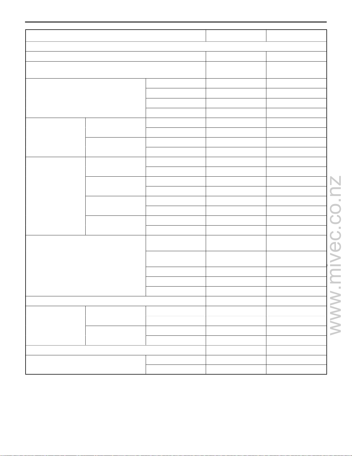
GENERAL INFORMATION
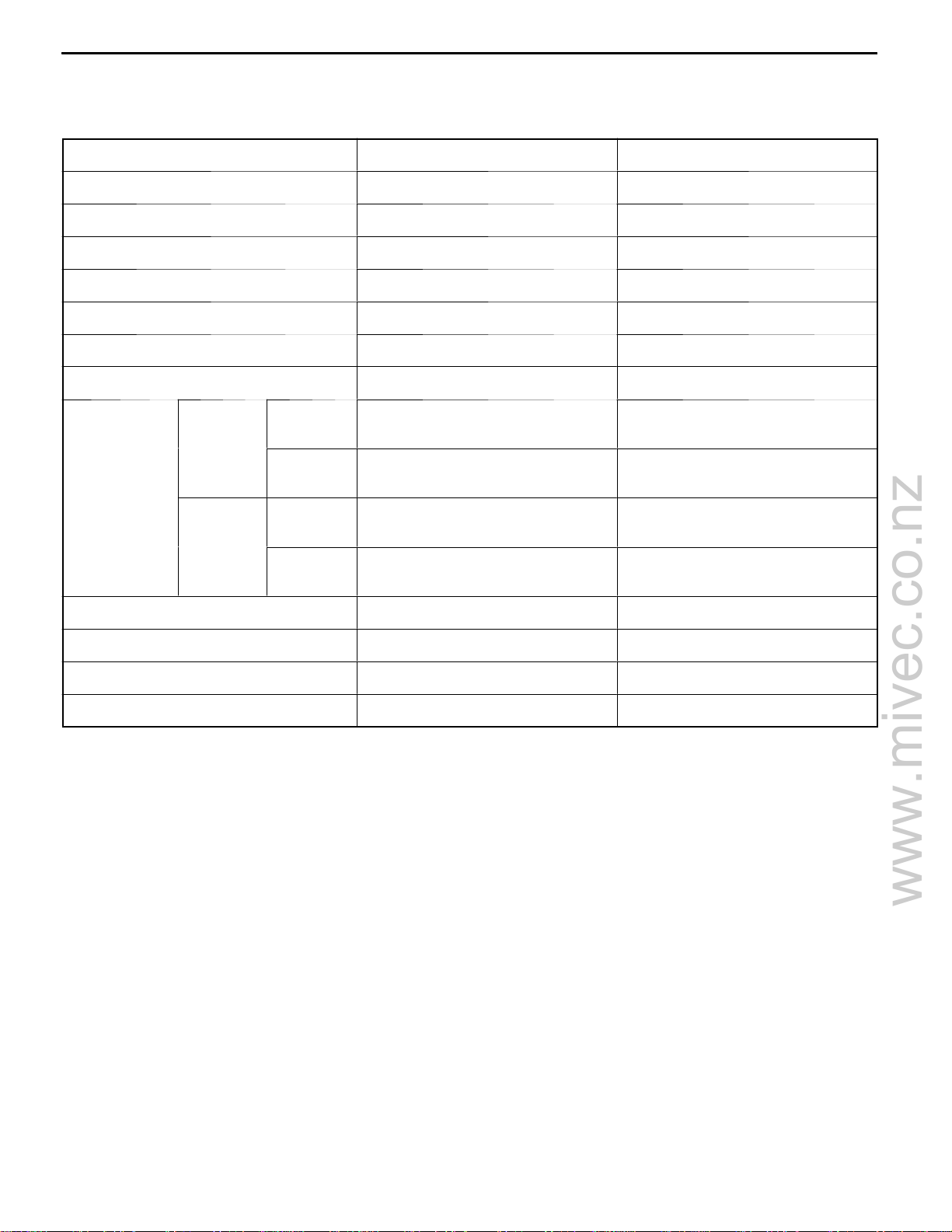
4G92
Descriptions 4G92- SOHC 4G92-DOHC- MIVEC
Type In-line OHV, SOHC In-line OHV, DOHC
Number of cylinders 4 4
Combustion chamber Pentroof type Pentroof type
11A-0-3
Total displacement dm
Cylinder bore mm 81.0 81.0
Piston stroke mm 77.5 77.5
Compression ratio 10.0 11.0
V alve timing Intake
Lubrication system Pressure feed, full-flow filtration Pressure feed, full-flow filtration
Oil pump type Trochoid type Trochoid type
Cooling system Water-cooled forced circulation Water-cooled forced circulation
Water pump type Centrifugal impeller type Centrifugal impeller type
3
valve
Exhaust
valve
Opens
(BTDC)
Closes
(ABDC)
Opens
(BBDC)
Closes
(ATDC)
1,597 1,597
20_,14_* 17_(Low-speed cam)
47.5_(High-speed cam)
42_,58_* 31_(Low-speed cam)
72.5_(High-speed cam)
54_,52_* 41_(Low-speed cam)
70_(High-speed cam)
2_,16_* 11_(Low-speed cam)
35_(High-speed cam)
*: LANCER for general export and CARISMA for 6B model
E
July 1997Mitsubishi Motors Corporation Revised
PWEE9502-C
Page 4
www.mivec.co.nz
11A-0-4
4G9 ENGINE (E- W) -
General Information
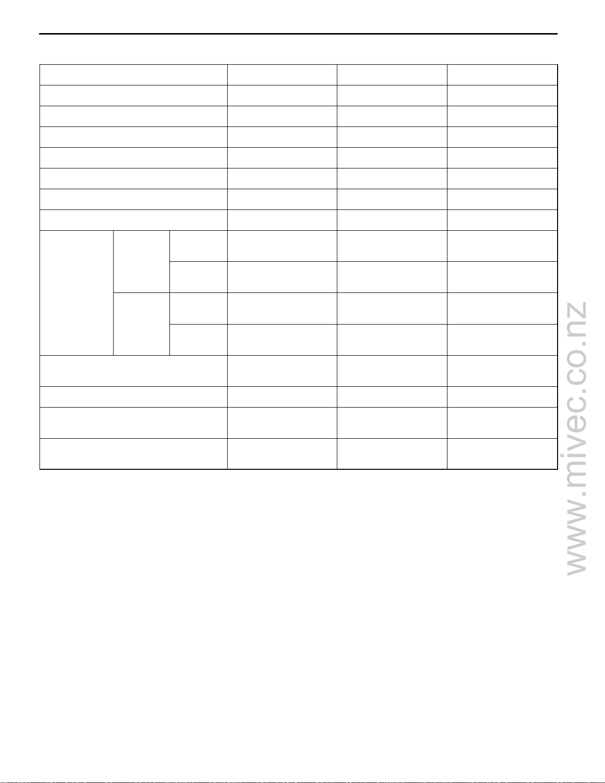
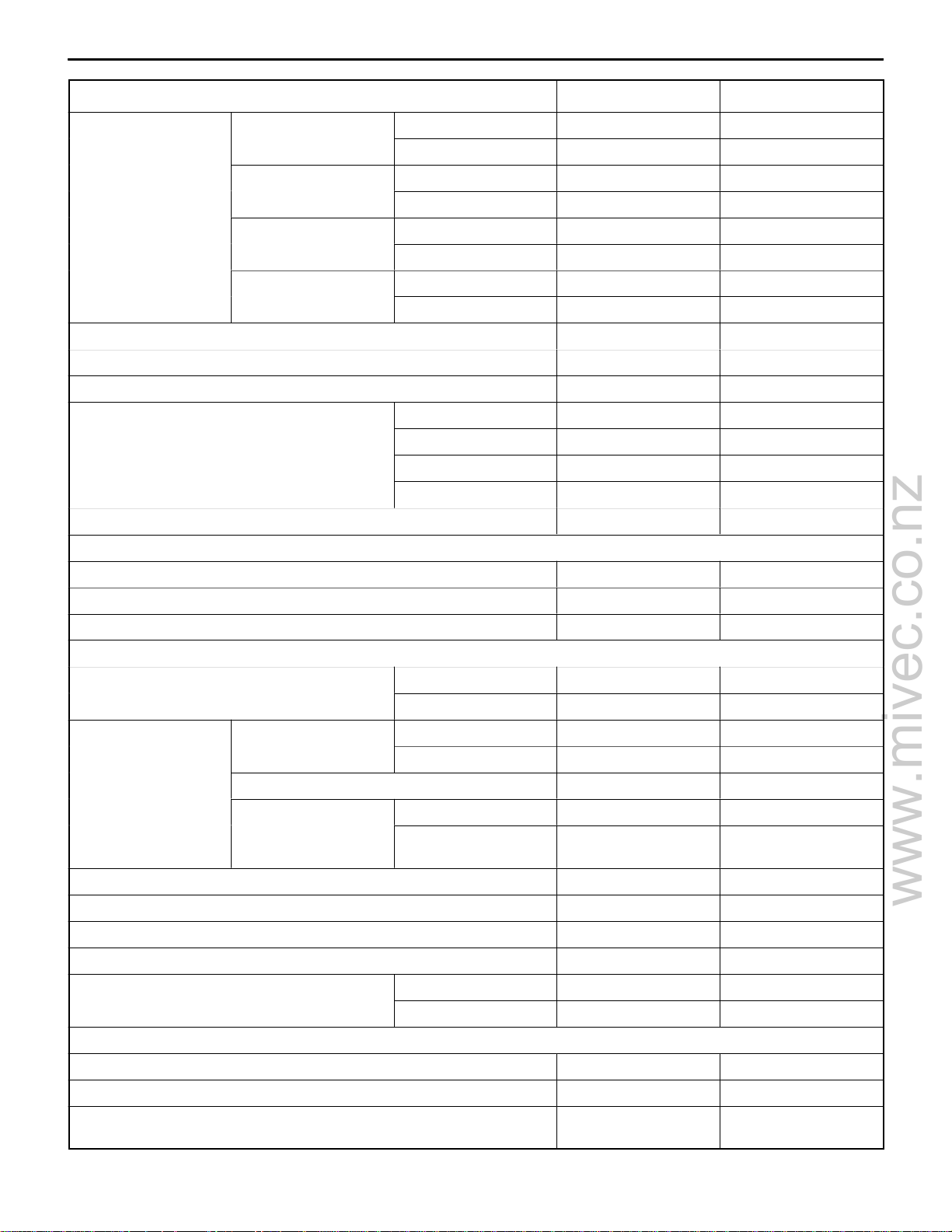
4G93
Descriptions 4G93-SOHC 4G93-DOHC 4G93- DOHC - GDI
Type In-line OHV, SOHC In-line OHV, DOHC In-line OHV, DOHC
Number of cylinders 4 4 4
Combustion chamber Pentroof type Pentroof type Pentroof type
Total displacement dm
Cylinder bore mm 81.0 81.0 81.0
Piston stroke mm 89.0 89.0 89.0
Compression ratio 10.0, 9.5 10.5 11.7*1, 12.0*
Valve timing Intake
Lubrication system Pressure feed, full-
Oil pump type Trochoid type Trochoid type Trochoid type
Cooling system Water-cooled forced
3
valve
Exhaust
valve
Opens
(BTDC)
Closes
(ABDC)
Opens
(BBDC)
Closes
(ATDC)
1,834 1,834 1,834
_
14
_
50
_
58
_
10
flow filtration
circulation
_
20
_
60
_
61
_
15
Pressure feed, fullflow filtration
Water-cooled forced
circulation
_
15
_
56
_
55
_
15
Pressure feed, fullflow filtration
Water-cooled forced
circulation
2
Water pump type Centrifugal impeller
type
*1: Up to 1999 model
2
*
: From 2000 model
Centrifugal impeller
type
Centrifugal impeller
type
E
May 2000Mitsubishi Motors Corporation Revised
PWEE9502-G
Page 5
www.mivec.co.nz
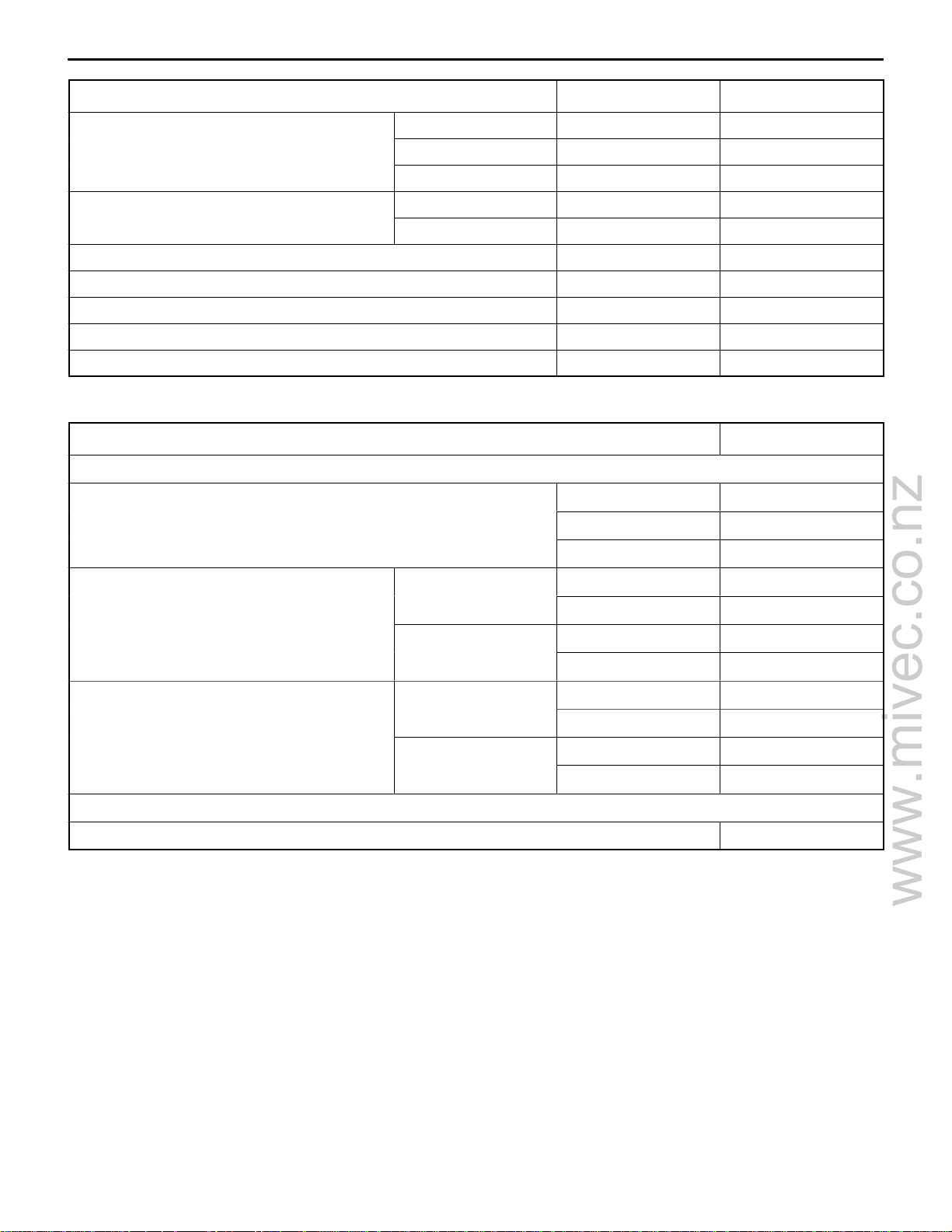
4G9 ENGINE (E–W) – General Information
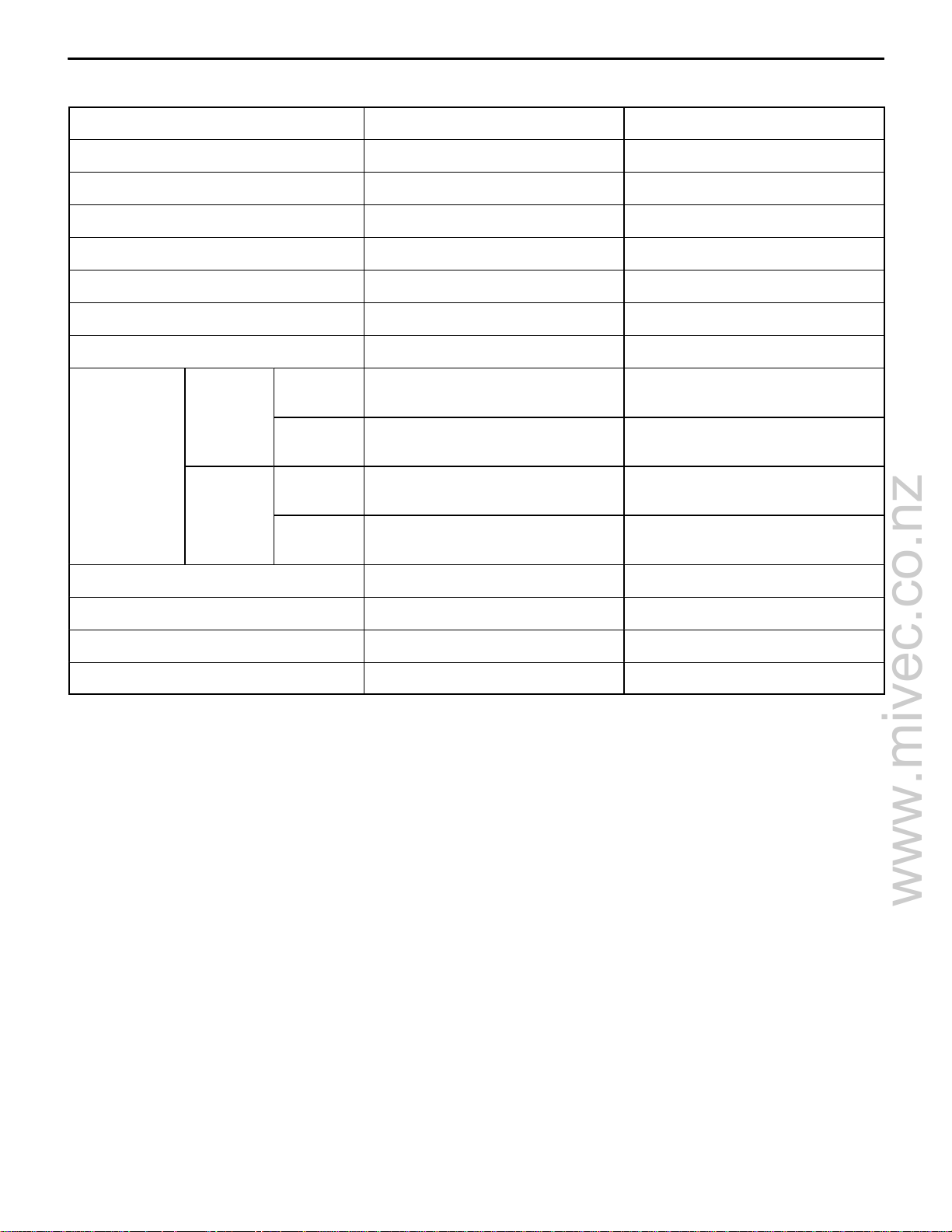
4G94
Descriptions 4G94–SOHC 4G94–DOHC–GDI
Type In-line OHV, SOHC In-line OHV, DOHC
Number of cylinders 4 4
Combustion chamber Pentroof type Pentroof type
11A-0-5
Total displacement dm
Cylinder bore mm 81.5 81.5
Piston stroke mm 95.8 95.8
Compression ratio 9.5 10.6
Valve timing Intake
Lubrication system Pressure feed, full-flow filtration Pressure feed, full-flow filtration
Oil pump type Trochoid type Trochoid type
Cooling system Water-cooled forced circulation Water-cooled forced circulation
Water pump type Centrifugal impeller type Centrifugal impeller type
3
valve
Exhaust
valve
Opens
(BTDC)
Closes
(ABDC)
Opens
(BBDC)
Closes
(ATDC)
1,999 1,999
2_ 15_
58_ 51_
58_ 55_
10_ 15_
E
E
July 1997Mitsubishi Motors Corporation Revised
Mar. 2001Mitsubishi Motors Corporation Revised
PWEE9502-C
PWEE9502-I
Page 6
www.mivec.co.nz
4G9 ENGINE (E–W) – Specifications
GSC
GSC
GSC
GSC
GSC
SC
GC
4G93 DOHC GDI
4G94 DOHC GDI
1. SPECIFICATIONS
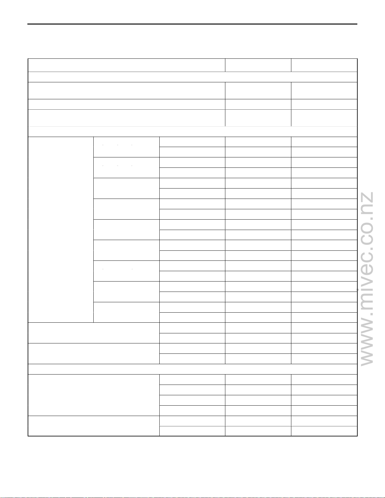
SERVICE SPECIFICATIONS
Items Standard value Limit
Timing belt
Auto-tensioner rod protrusion amount (When removed from engine)mm11 –
Auto-tensioner rod stroke mm Within 1 –
Auto-tensioner rod protrusion amount (When checking with installed
on engine) mm
Rocker arms and camshaft
Camshaft cam
height mm
Valve clearance mm Intake 0.09 –
Camshaft journal O.D. mm SOHC 26.0 –
Rocker cover and camshaft (MIVEC)
Camshaft height mm Intake A 36.41 36.91
Valve clearance (cold engine) mm Intake 0.1 –
4G92–SOHC*
4G92–SOHC*
4G92–SOHC*
4G93–SOHC*
4G93–SOHC*
4G94–SOHC
4G93–DOHC
4G93–DOHC–GDI
4G94–DOHC–GDI
1
2
3
4
5
Intake 37.34 36.84
Exhaust 36.79 36.29
Intake 37.78 37.28
Exhaust 37.83 37.33
Intake 36.92 36.42
Exhaust 36.70 36.65
Intake 37.53 37.03
Exhaust 37.64 37.14
Intake 37.11 36.61
Exhaust 37.15 36.65
Intake 37.91 37.41
Exhaust 37.70 37.20
Intake 35.31 34.81
Exhaust 35.20 34.70
Intake 35.49 34.99
Exhaust 34.73 34.23
Intake 35.49 34.99
Exhaust 34.91 34.41
Exhaust 0.20 –
DOHC 45.0 –
Intake B 33.58 33.08
Exhaust A 35.83 35.33
Exhaust B 34.24 33.74
Exhaust 0.2 –
3.8 – 4.5 –
11A-1-1
*1: LANCER for Europe and CARISMA for Europe
*2: LANCER for general export and CARISMA for 6B model
*3: LANCER for Europe (from 2001 model) and CARISMA for Europe (from 2001 model)
*4: Except for Europe
*5: For Europe
E
Jun. 2002Mitsubishi Motors Corporation Revised
PWEE9502-K
Page 7
www.mivec.co.nz
11A-1-2
Items Standard value Limit
Cylinder head and valve
Cylinder head gasket surface flatness mm Less than 0.03 0.2
4G9 ENGINE (E–W) – Specifications
Grinding limit of cylinder head gasket surface mm
*Total resurfacing depth of both cylinder head and cylinder block
Cylinder head overall height mm SOHC 119.9 – 120.1 –
DOHC 131.9 – 132.1 –
DOHC–MIVEC 119.8 – 120.0 –
DOHC–GDI 131.9 – 132.1 –
Thickness of valve
head (margin) mm
Valve overall height
mm
SOHC Intake 1.0 0.5
Exhaust 1.3 0.8
DOHC Intake 1.0 0.5
Exhaust 1.2 0.7
SOHC Intake 110.15 109.65
Exhaust 113.70 113.20
DOHC Intake 104.19 103.69
Exhaust 103.87 103.37
DOHC–MIVEC Intake 115.63 115.13
Exhaust 115.63 115.13
DOHC–GDI Intake 104.19 103.69
Exhaust 103.87 103.37
– 0.2*
Valve spring free length mm SOHC (with lash ad-
juster)
SOHC (with adjust-
ing screw)
DOHC 45.0 44.0
DOHC–MIVEC 51.5 50.5
DOHC–GDI 44.8 43.8
Valve spring out-of-squareness Max. 2_ 4_
Valve stem to valve
guide clearance mm for PAJERO io
Valve seat valve contact width mm 0.9 – 1.3 –
Valve guide projection from cylinder head
upper surface mm
Except DOHC–GDI
DOHC–GDI
for PAJERO io
Intake 0.02 – 0.05 0.10
Exhaust 0.05 – 0.09 0.15
Intake 0.02 – 0.05 0.10
Exhaust 0.04– 0.06 0.15
SOHC 14.0 –
DOHC 19.0 –
50.9 49.9
49.5 48.5
E
Jun. 2002Mitsubishi Motors Corporation Revised
PWEE9502-K
Page 8
www.mivec.co.nz
4G9 ENGINE (E–W) – Specifications
Items LimitStandard value
11A-1-3
Valve stem projection mm
Cylinder head bolt shank length mm – 96.4
Valve stem O.D. mm 6.0 –
V alve face angle 45_ – 45.5_ –
Valve spring load/installed height N/mm SOHC 216/44.2 –
Valve guide I.D. mm 6.0 –
Font case, oil pump and oil pan
Oil pump tip clearance mm 0.06 – 0.18 –
SOHC Intake 49.30 49.80
Exhaust 49.35 49.85
DOHC Intake 46.70 47.20
Exhaust 46.65 47.15
DOHC–MIVEC Intake 58.13 58.63
Exhaust 57.85 58.35
DOHC–GDI Intake 46.70 47.20
Exhaust 46.65 47.15
DOHC 255/44.5 –
DOHC–MIVEC 255/44.5 –
DOHC–GDI 196/37.5 –
Oil pump side clearance mm 0.04 – 0.10 –
Oil pump body clearance mm 0.10 – 0.18 0.35
Piston and connecting rod
Piston ring to piston ring groove clearance
mm
Piston ring end gap
mm
Crankshaft pin oil clearance mm 0.02 – 0.05 0.1
Piston pin press-in load N [Room temperature] 4,500 – 14,700 –
Connecting rod big end side clearance mm 0.10 – 0.25 0.4
Piston pin O.D. mm 19.0 –
Piston O.D. mm 4G92, 4G93 81.0 –
Crankshaft, cylinder block, flywheel and drive plate
No. 1 4G92, 4G93 0.25 – 0.40 0.8
No. 2 0.40 – 0.55 0.8
Oil ring SOHC (4G92, 4G93) 0.20 – 0.60 1.0
No. 1 0.03 – 0.07 0.1
No. 2 0.02 – 0.06 0.1
4G94 0.15 – 0.30 0.8
SOHC (4G94),
DOHC
4G94 81.5 –
0.10 – 0.35 1.0
Crankshaft journal oil clearance mm 0.02 – 0.04 0.1
Cylinder block gasket surface flatness mm 0.05 0.1
Grinding limit of cylinder block gasket surface mm
*Total resurfacing depth of both cylinder head and cylinder block
E
Mar . 2001Mitsubishi Motors Corporation Revised
PWEE9502-I
– 0.2*
Page 9
www.mivec.co.nz
11A-1-4
Items LimitStandard value
Cylinder block overall height mm 4G92 243.5 –
Cylinder block I.D. mm 4G92, 4G93 81.0 –
Piston to cylinder clearance mm 0.02 – 0.04 –
Bearing cap bolt shank length mm – 71.1
Crankshaft end play mm 0.05 – 0.25 0.4
Crankshaft journal O.D. mm 50 –
Crankshaft pin O.D. mm 45 –
4G9 ENGINE (E–W) – Specifications
4G93 263.5 –
4G94 286.7 –
4G94 81.5 –
REWORK DIMENSIONS
Items Standard value
Cylinder head and valve
Oversize rework dimensions of valve guide hole (both intake and
exhaust) mm
Oversize rework dimensions of intake valve
seat hole mm
Oversize rework dimensions of exhaust valve
seat hole mm
Crankshaft, flywheel and drive plate
Crankshaft out of roundness and taper of journal and pin mm 0.005
NOTE
O.D.: Outer diameter
I.D.: Inner diameter
O.S.: Oversize diameter
SOHC 0.30 O.S. 31.80 – 31.83
DOHC 0.30 O.S. 34.30 – 34.32
SOHC 0.30 O.S. 29.30 – 29.32
DOHC 0.30 O.S. 30.80 – 30.82
0.05 O.S. 11.05 – 11.07
0.25 O.S. 11.25 – 11.27
0.50 O.S. 11.50 – 11.52
0.60 O.S. 32.10 – 32.13
0.60 O.S. 34.60 – 34.62
0.60 O.S. 29.60 – 29.62
0.60 O.S. 31.10 – 31.13
E
Mar . 2001Mitsubishi Motors Corporation Revised
PWEE9502-I
Page 10

www.mivec.co.nz
4G9 ENGINE (E–W) – Specifications
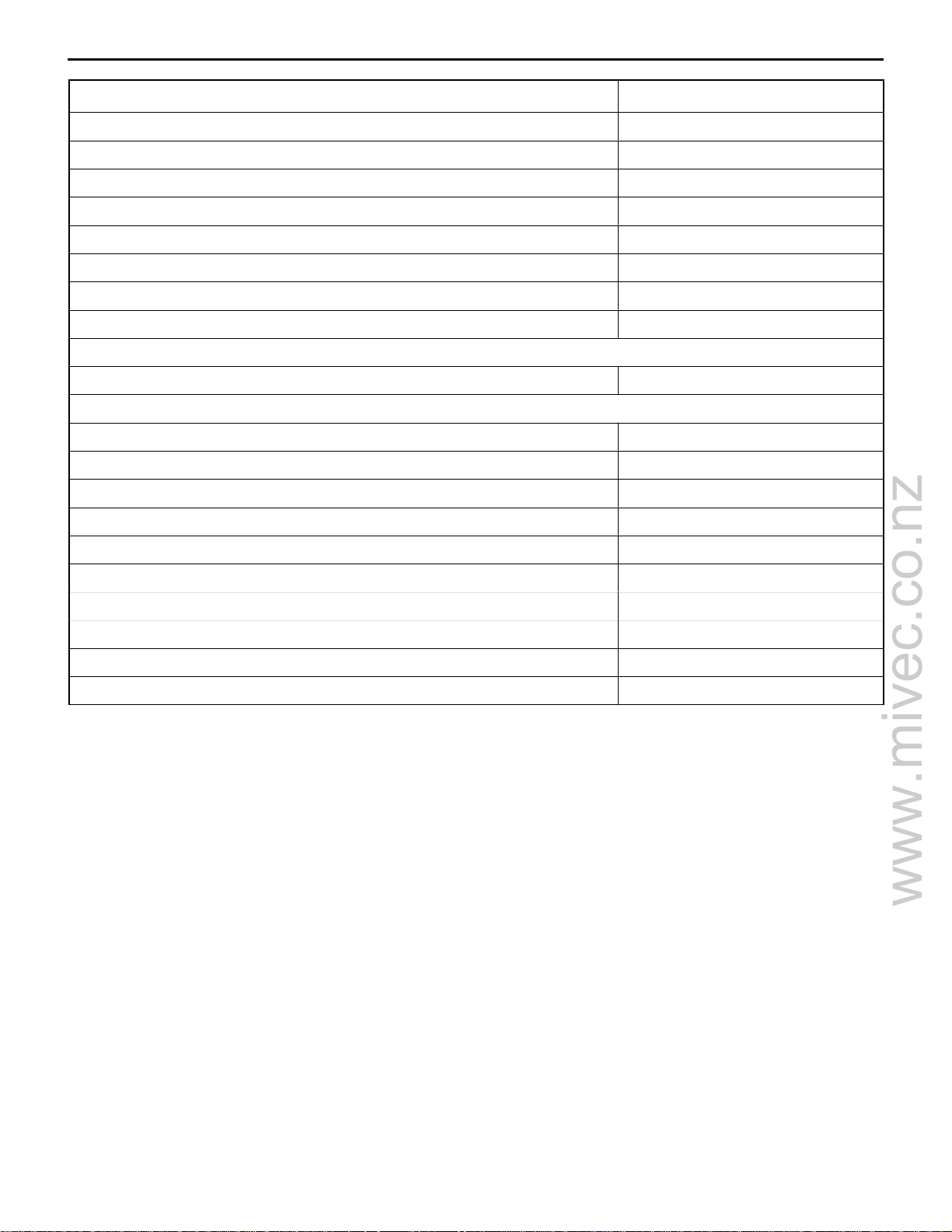
TORQUE SPECIFICATIONS
Items Nm
Alternator and ignition system
Oil level gauge 13
Distributor 12
Ignition coil 10
Spark plug 25
Crankshaft bolt 182 ± 4
Alternator brace (M8) 23
Alternator brace (M10) 49
Lock bolt 23
Adjusting bolt 5
Power steering pump pulley 25
Power steering pump bracket stay 49
Power steering pump bracket (M8) 21
11A-1-5
Power steering pump bracket (M10) 44
Alternator pivot bolt 44
Center cover 3
Ignition failure sensor (M6) 5
Ignition failure sensor (M8) 23
Ignition failure sensor bracket 10
Cam position sensor 9
Cam position sensor support 13
Cam position sensing cylinder 21
Engine cover 2.9
Timing belt
Camshaft sprocket bolt 88
Cam position sensor 9.8
Crank angle sensor 9.8
Timing belt rear cover 11
Timing belt rear upper cover 11
Timing belt tensioner 24
Engine support bracket, right 49
Accessory mount 49
Timing belt cover 11
Tensioner pulley bolt 49
Tensioner arm bolt 44
Auto-tensioner bolt 13
Idler pulley bolt 36
E
Jun. 2002Mitsubishi Motors Corporation Revised
PWEE9502-K
Page 11

www.mivec.co.nz
11A-1-6
Items Nm
Fuel system and emission system
Breather tube 21
Fuel pump 18
Carburetor 17
EGR valve 21
Cover <Without EGR valve> 12
Fuel return pipe 9
Delivery pipe 12
Fuel pressure regulator 9
Throttle body stay <MIVEC> 23
Throttle body stay <4G94> 24
Throttle body 19
Throttle cable bracket 19
Stay 24
4G9 ENGINE (E–W) – Specifications
Harness bracket 11
Vacuum hose and pipe assembly <Engine with solenoid valve> (Flange bolt) 11
Vacuum hose and pipe assembly <Engine with solenoid valve> (Bolt and
washer assembly)
Vacuum hose and pipe assembly <Engine without solenoid valve> 10
Solenoid valve assembly 9
Throttle body and EGR system (GDI)
Air intake resonator 9
Intake manifold stay (M8) 20
Intake manifold stay (M10) 30
Water hose clamp 13
Water pipe 11
Throttle body 18
Throttle body stay
<CARISMA from 2001 model, SPACE STAR from 2001 model, GALANT>
Throttle body stay <For PAJERO io – 4G94> 18
EGR valve (Bolt and washer assembly) 18
9
24
EGR valve (Flange bolt) 24
Engine hanger 18
EGR valve support bolt 18
EGR valve support nut 23
Air by-pass valve 9
Mar . 2001Mitsubishi Motors Corporation RevisedPWEE9502-K
E
E
Jun. 2002Mitsubishi Motors Corporation Revised
PWEE9502-I
Page 12

www.mivec.co.nz
4G9 ENGINE (E–W) – Specifications
Items Nm
Intake manifold and exhaust manifold
Exhaust manifold (M8) 18
Exhaust manifold (M10) 29
Exhaust manifold bracket (M8) 19
Exhaust manifold bracket (M10 Bolt and washer assembly) 35
Exhaust manifold bracket (M10 Flange bolt) 98
Engine hanger (Bolt with head mark “4”) 12
Engine hanger (Bolt with head mark “7”) 19
Oil level gauge guide 14
Boost sensor 5
Intake air temperature sensor 13
Heat protector 13
Intake manifold 20
Intake manifold stay 31
11A-1-6a
Oxygen sensor 44
Intake manifold (GDI)
Vacuum pipe and hose <Except for PAJERO io> 11
Vacuum pipe and hose <For PAJERO io> 9
Solenoid valve 9
Fuel pump protector 23
Connector bracket 11
Branch tube (M6 x 14) 11
Branch tube (M6 x 18) 9
Intake manifold stay 30
Accelerator cable bracket 9
V acuum pipe 11
Intake manifold 19
Exhaust manifold (GDI)
Oil level gauge guide 13
Exhaust manifold cover 13
Engine hanger bolt 24
Engine hanger nut (M8) 18
Engine hanger nut (M10) 29
Exhaust manifold bracket (M8 × 20) 18
Exhaust manifold bracket (M8 × 22) 35
Exhaust manifold bracket (M8 × 25) 19
Exhaust manifold bracket (M10) 35
Exhaust manifold bracket <For PAJERO io> 98
E
Jun. 2002Mitsubishi Motors Corporation Revised
PWEE9502-K
Page 13

www.mivec.co.nz
11A-1-6b
Items Nm
Exhaust manifold (M8) 17
Exhaust manifold (M10) 29
Injector and fuel pump assembly (GDI)
Fuel low pressure pipe (M6) 18
Fuel low pressure pipe (M8) 9
Fuel nipple 9
Clamp 9
Fuel feed pipe 11
Fuel pump 17
Harness bracket 11
Fuel pipe 11
Fuel return pipe 11
Fuel return pipe clamp 9
Fuel high pressure regulator 18
4G9 ENGINE (E–W) – Specifications
Fuel pressure sensor <Except for PAJERO io> 23
Fuel pressure sensor <For PAJERO io> 18
Spacer 18
Pump camshaft case 23
Injector holder 22
Delivery pipe and injector 11
Intake and exhaust manifold <4G94–GDI for PAJERO io>
V acuum pipe and hose 9
Solenoid valve 9
Fuel pump protector 23
Connector bracket 11
Intake manifold stay nut 29
Intake manifold stay bolt 31
Low pressure fuel pipe 9
Intake manifold 20
Exhaust manifold cover 13
Engine hanger 18
Exhaust manifold bracket 98
Exhaust manifold (M8) 17
Exhaust manifold (M10) 29
Water pump and water hose
Water pump 24
Water inlet pipe 14
Thermostat case 24
E
Jun. 2002Mitsubishi Motors Corporation Revised
PWEE9502-K
Page 14

www.mivec.co.nz
4G9 ENGINE (E–W) – Specifications
Items Nm
Water inlet fitting <Except PAJERO io> 19
Water inlet fitting <PAJERO io> 24
Water by-pass fitting 24
Water pipe 14
Water outlet fitting <Except PAJERO io> 19
Water outlet fitting <PAJERO io> 24
Engine coolant temperature gauge unit 10
Engine coolant temperature sensor 29
Water fitting 24
Rocker arms and camshaft
Lock nut 9
Rocker arm shaft 31
Harness bracket 10
Rocker cover 3.5
11A-1-6c
Bearing cap bolt (M6) 11
Bearing cap bolt (M8) 24
Beam camshaft cap (M6) 11
Beam camshaft cap (M8) 21
Rocker cover and camshafts (MIVEC)
Rocker cover 4
Oil pump 11
Arm spring holder 11
Camshaft bearing cap (M6) 11
Camshaft bearing cap (M8) 23
Oil control valve 9
Rocker arms and rocker shaft caps (MIVEC)
Rocker shaft cap 11
Cylinder head and valves
CylInder head bolt 74 Nm and then completely loosen,
finally tighten 20 Nm + 90_ + 90_
Oil pressure switch 10
Front case and oil pump
Oil pump cover 10
Oil pump case 14
Relief plug 44
Oil screen 19
Oil pan 9
Upper oil pan (M6) 9
E
Jun. 2002Mitsubishi Motors Corporation Revised
PWEE9502-K
Page 15
www.mivec.co.nz
11A-1-6d
Items Nm
Upper oil pan (M8) 24
Lower oil pan 11
Cover 7
Baffle plate <DOHC–MPI> 7
Baffle plate <Except DOHC–MPI> 11
Drain plug 39
Oil pressure switch 10
Transmission stay 23
Piston and connecting rod
Connecting rod cap nut 20 + 90_ to 100_
Crankshaft, cylinder block, flywheel and drive plate
Bearing cap bolt 25 + 90_ to 100_
Oil seal case 11
Bell housing cover (Flange bolt) 10
4G9 ENGINE (E–W) – Specifications
Bell housing cover (Bolt and washer assembly) 9
Rear plate <SPACE STAR> 10
Rear plate <Except SPACE STAR> 11
Drive plate bolt 98
Flywheel bolt 98
Baffle plate 9
Knock sensor 23
E
Jun. 2002Mitsubishi Motors Corporation Revised
PWEE9502-K
Page 16
www.mivec.co.nz
4G9 ENGINE (E- W) -
Specifications
11A-1-7
NEW TIGHTENING METHOD - BY USE OF BOLTS TO BE TIGHTENED IN PLASTIC AREA
A new type of bolts, to be tightened in plastic area, is currently used for some parts of the engine.
The tightening method for bolts of this type is different from the conventional one. Be sure to observe
the method described in the text when tightening the bolts.
Service limits are provided for the bolts. Make sure that the service limits described in the text are strictly
observed.
D
Areas where the bolts are in use:
(1) Cylinder head bolts
(2) Main bearing cap bolts
(3) Connecting rod cap bolts
D
Tightening method
After tightening the bolts to the specified torque, tighten them another 90_or 180_(twice 90_). The
tightening method varies on different areas. Observe the tightening method described in the text.
SEALANT
Items Specified sealant Quantity
Water pump Mitsubishi Genuine Part No.MD970389 or equivalent As required
Thermostat case Mitsubishi Genuine Part No.MD970389 or equivalent As required
Water by-pass fitting Mitsubishi Genuine Part No.MD970389 or equivalent As required
Water fitting Mitsubishi Genuine Part No.MD970389 or equivalent As required
Engine coolant temperature sensor 3M Nut Locking Part No.4171 or equivalent As required
Engine coolant temperature gauge unit 3M ATD Part No.8660 or equivalent As required
Camshaft bearing cap 3M ATD Part No.8660 or equivalent As required
Semi-circular packing 3M ATD Part No.8660 or equivalent As required
Rocker cover 3M ATD Part No.8660 or equivalent As required
Beam camshaft cap Mitsubishi Genuine Part No.MD970389 or equivalent As required
Cover 3M ATD Part No.8660 or equivalent As required
Cylinder head Mitsubishi Genuine Part No.MD970389 or equivalent As required
Oil pressure switch 3M ATD Part No.8660 or equivalent As required
Water outlet fitting Mitsubishi Genuine Part No.MD970389 or equivalent As required
Oil pump case Mitsubishi Genuine Part No.MD970389 or equivalent As required
Oil pan/Upper oil pan/Lower oil pan Mitsubishi Genuine Part No.MD970389 or equivalent As required
Oil seal case Mitsubishi Genuine Part No.MD970389 or equivalent As required
Drive plate bolt 3M Nut Locking Part No.4171 or equivalent As required
Flywheel bolt 3M Nut Locking Part No.4171 or equivalent As required
Cam position sensor support Mitsubishi Genuine Part No.MD970389 or equivalent As required
Oil control valve 3M ATD Part No.8660 or equivalent As required
Camshaft holder 3M ATD Part No.8660 or equivalent As required
E
July 2000Mitsubishi Motors Corporation Revised
PWEE9502-H
Page 17

www.mivec.co.nz
11A-1-8
4G9 ENGINE (E-W) -
Specifications
FORM-IN-PLACE GASKET
The engine has several areas where the form-in-place gasket (FIPG) is in use. To ensure that the gasket
fully serves its purpose, it is necessary to observe some precautions when applying the gasket. Bead
size, continuity and location are of paramount importance. Too thin a bead could cause leaks. Too thick
a bead, on the other hand, could be squeezed out of location, causing blocking or narrowing of the
fluid feed line. To eliminate the possibility of leaks from a joint, therefore, it is absolutely necessary to
apply the gasket evenly without a break, while observing the correct bead size.
The FIPG used in the engine is a room temperature vulcanization (RTV) type and is supplied in a 100-gram
tube (Part No. MD970389 or MD997110). Since the RTV hardens as it reacts with the moisture in the
atomospheric air, it is normally used in the metallic flange areas. The FIPG, Part No. MD970389, can
be used for sealing both engine oil and coolant, while Part No. 997110 can only be used for engine
oil sealing.
Disassembly
The parts assembled with the FIPG can be easily disassembled without use of a special method. In
some cases, however, the sealant between the joined surfaces may have to be broken by lightly striking
with a mallet or similar tool. A flat and thin gasket scraper may be lightly hammered in between the
joined surfaces. In this case, however, care must be taken to prevent damage to the joined surfaces.
For removal of the oil pan, the special tool “Oil Pan Remover” (MD998727) is available. Be sure to use
the special tool to remove the oil pan. <Except aluminium die-cast oil pans>
Surface Preparation
Thoroughly remove all substances deposited on the gasket application surfaces, using a gasket scraper
or wire brush. Check to ensure that the surfaces to which the FIPG is to be applied is flat. Make sure
that there are no oils, greases and foreign substances deposited on the application surfaces. Do not
forget to remove the old sealant remained in the bolt holes.
Form-In-Place Gasket Application
When assembling parts with the FIPG, you must observe some precautions, but the procedures is very
simple as in the case of a conventional precut gasket.
Applied FIPG bead should be of the specified size and without breaks. Also be sure to encircle the
bolt hole circumference with a completely continuous bead. The FIPG can be wiped away unless it is
hardened. While the FIPG is still moist (in less than 15 minutes), mount the parts in position. When
the parts are mounted, make sure that the gasket is applied to the required area only. In addition, do
not apply any oil or water to the sealing locations or start the engine until a sufficient amount of time
(about one hour) has passed after installation is completed.
The FIPG application procedure may vary on different areas. Observe the procedure described in the
text when applying the FIPG.
E
May 1995Mitsubishi Motors Corporation
PWEE9502
Page 18

www.mivec.co.nz
4G9 ENGINE (E-W) -
Special Tools
2. SPECIAL TOOLS
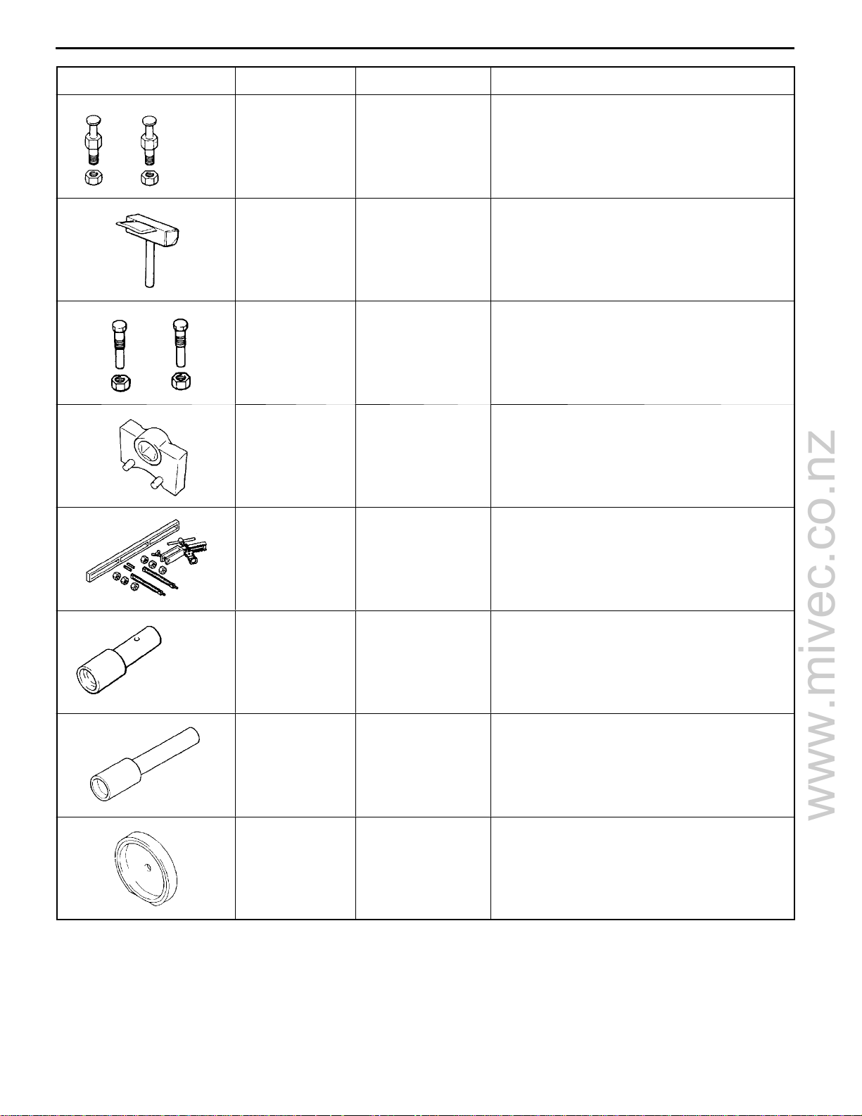
Tool Number Name Use
MB990938 Handle Use with MD998776
11A-2-1
MB990767 Crankshaft pulley
holder
MD998440 Leak-down tester Leak-down test of lash adjuster
MD998442 Air bleed wire Air bleeding of lash adjuster
MD998713 Camshaft oil seal
installer
Holding camshaft sprocket when loosening
and tightening of bolt.
Use with MD998719
Installation of camshaft oil seal
MD998716 Crankshaft wrench Rotation of crankshaft when installing piston
and timing belt.
MD998717 Crankshaft front oil
seal installer
MB991653 Cylinder head bolt
wrench
MB991659 Guide D Removal of piston pin (Use with MD998780)
Installation of crankshaft front oil seal
Tightening and loosening of cylinder head bolt
E
Nov. 1995Mitsubishi Motors Corporation Revised
PWEE9502-A
Page 19
www.mivec.co.nz
11A-2-2
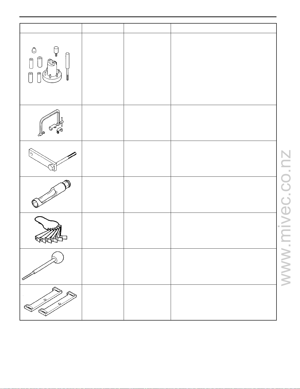
Tool UseNameNumber
4G9 ENGINE (E-W) -
Special Tools
MD998719 Pulley holder pin
(2)
MD998727 Oil pan remover Removal of the oil pan
MD998754 Pin Use with MB990767
MD998767 Tensioner pulley
socket wrench
Use with MB990767
Adjustment of timing belt tension
MD998772 Valve spring
compressor
MD998774 Valve stem seal
installer
MD998775 Valve stem seal
installer
MD998776 Crankshaft rear oil
seal installer
Removal and installation of valve and related
parts
Installation of valve stem seal
Installation of valve stem seal
Installation of crankshaft rear oil seal
Use with MB990938
E
Nov. 1995Mitsubishi Motors Corporation
PWEE9502-A
Revised
Page 20
www.mivec.co.nz
4G9 ENGINE (E-W) -
Tool UseNameNumber
Special Tools
11A-2-3
MD998780 SETTING TOOL
Piston pin
MD998735 Valve spring
compressor
MD998781 Flywheel stopper Holding flywheel and drive plate
Removal and installation of piston pin
Compression of valve spring
MB991477 Valve adjusting
wrench
MB991478 Valve adjusting
wrench feeler
gauge set
MB991479 Rocker arm
piston checker
MD998784 Valve spring
compressor
adapter
Adjustment of valve clearance (MIVEC)
Adjustment of valve clearance (MIVEC)
Adjustment of valve clearance (MIVEC)
Compression of valve spring (MIVEC)
(Use with MD998772)
E
Nov. 1995Mitsubishi Motors Corporation Revised
PWEE9502-A
Page 21
www.mivec.co.nz
4G9 ENGINE (E–W) – Alternator and Ignition System
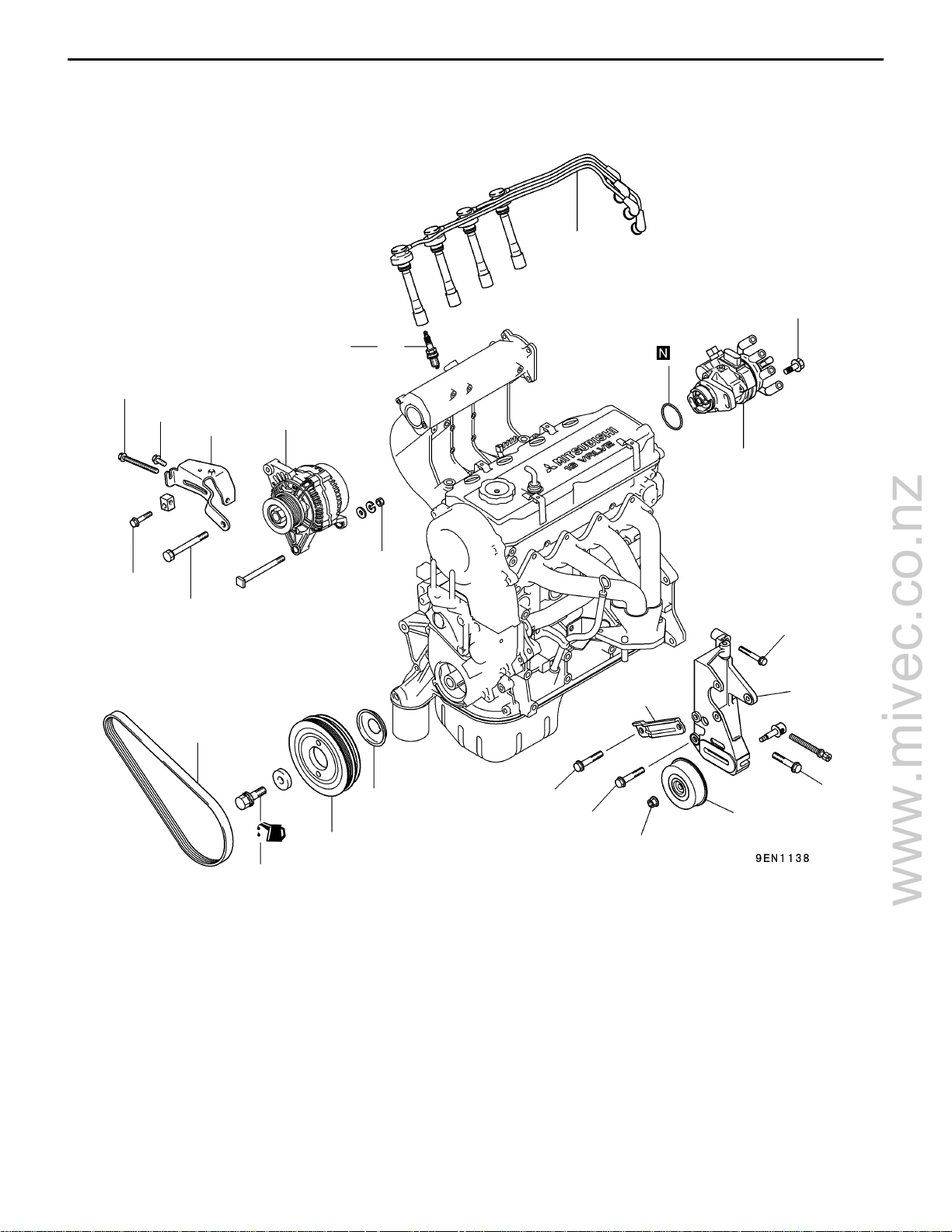
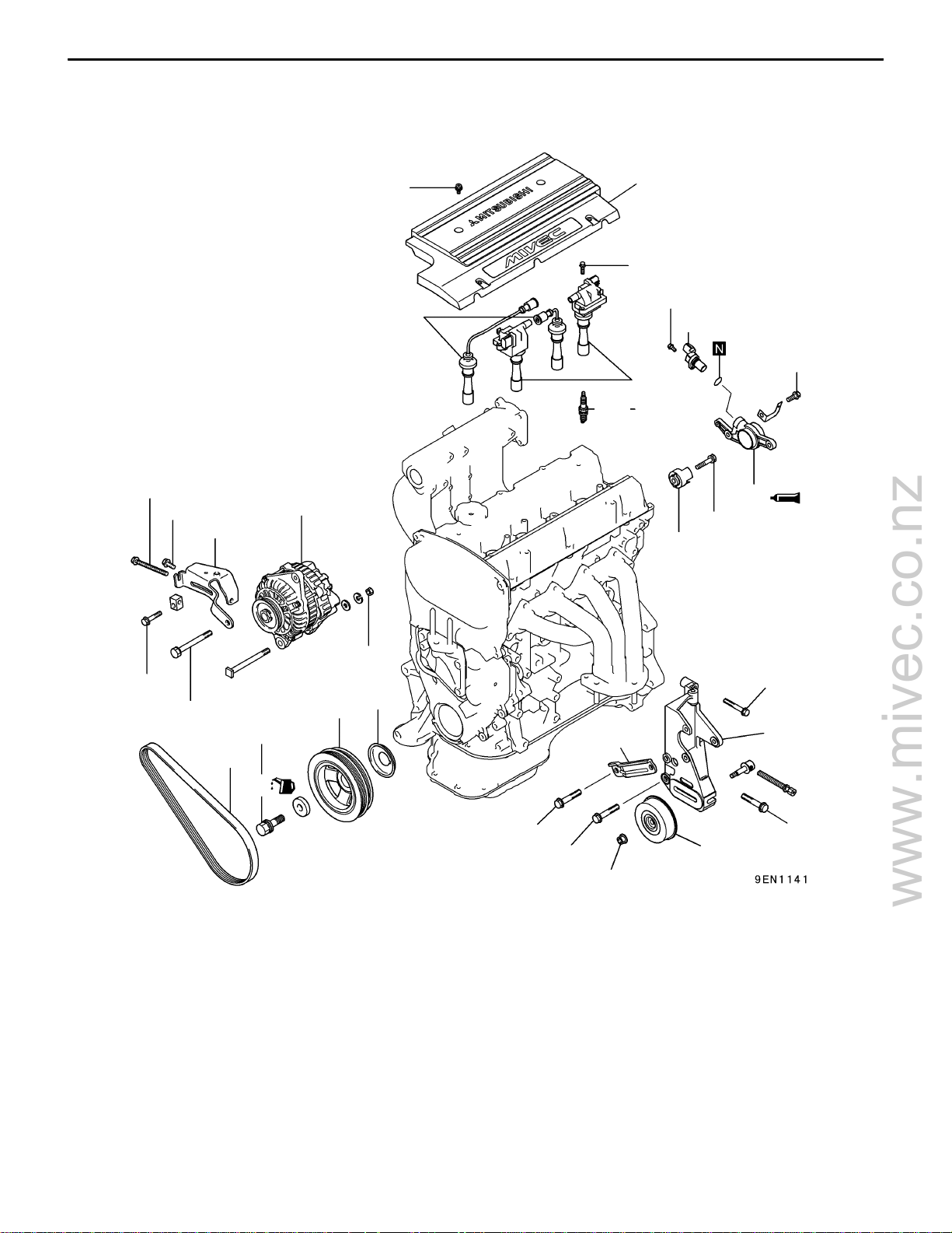
3. ALTERNATOR AND IGNITION SYSTEM
REMOVAL AND INSTALLATION <SOHC> (Engines with distributor)
7
11A-3-1
12 Nm
5 Nm
23 Nm
23 Nm
49 Nm
25 Nm
3
2
8
9
10
44 Nm
21 Nm
12
13
1
6
4
5
49 Nm
44 Nm
11
25 Nm
44 Nm
182 ± 4 Nm
Removal steps
1. Drive belt*
2. Alternator
3. Alternator brace
AA""BA 4. Crankshaft bolt
"BA 5. Crankshaft pulley
"BA 6. Front flange
7. Spark plug cable
E
Apr. 2002Mitsubishi Motors Corporation Revised
PWEE9502-J
8. Spark plug
9. O-ring
10. Distributor
11. Power steering pump pulley
12. Power steering pump bracket stay
13. Power steering pump bracket
NOTE:
*: For details of adjustment, refer to the relevant model’s
chassis workshop manual.
Page 22
www.mivec.co.nz
11A-3-2
4G9 ENGINE (E–W) – Alternator and Ignition System
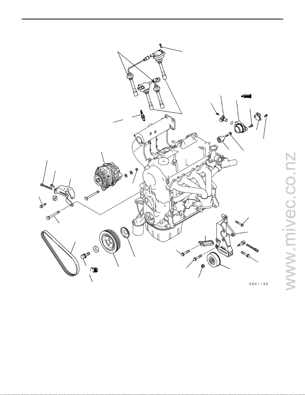
REMOVAL AND INSTALLATION <SOHC for other than PAJERO io>
(Engines without distributor)
23 Nm
5 Nm
23 Nm
7
9
25 Nm
10 Nm
8
9 Nm
11
12
13 Nm
10
5 Nm
2
13
21 Nm
3
44 Nm
49 Nm
1
4
182 ± 4 Nm
Removal steps
1. Drive belt*
2. Alternator
3. Alternator brace
AA""BA 4. Crankshaft bolt
"BA 5. Crankshaft pulley
"BA 6. Front flange
7. Spark plug cable
8. Ignition coil
9. Spark plug
10. Ignition failure sensor (From 2001
model vehicles for Europe)
21 Nm
15
49 Nm
16
6
44 Nm
5
NOTE:
*: For details of adjustment, refer to the relevant model’s
chassis workshop manual.
44 Nm
25 Nm
11. Cam position sensor
"AA 12. Cam position sensor support
13. Cam position sensing cylinder
14. Power steering pump pulley
15. Power steering pump bracket stay
16. Power steering pump bracket
14
E
Apr. 2002Mitsubishi Motors Corporation Revised
PWEE9502-J
Page 23
www.mivec.co.nz
4G9 ENGINE (E–W) – Alternator and Ignition System
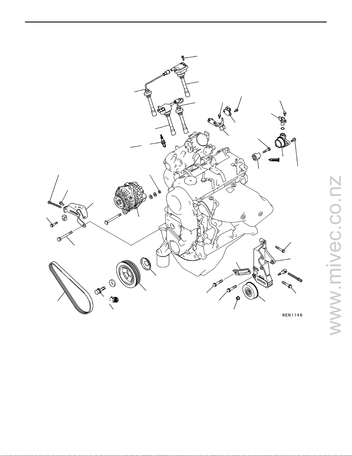
REMOVAL AND INSTALLATION <SOHC for PAJERO io>
(Engines without distributor)
10 Nm
8
11A-3-2a
23 Nm
5 Nm
23 Nm
49 Nm
7
7
10 Nm
5 Nm
9 Nm
12
11
10
21 Nm
25 Nm
8
9
13
44 Nm
14
13 Nm
3
2
21 Nm
16 17
1
Removal steps
1. Drive belt*
2. Alternator
3. Alternator brace
AA""BA 4. Crankshaft bolt
"BA 5. Crankshaft pulley
"BA 6. Front flange
7. Spark plug cable
8. Ignition coil
9. Spark plug
E
4
182 ± 4 Nm
Jun. 2002Mitsubishi Motors Corporation Revised
5
6
PWEE9502-K
49 Nm
44 Nm
25 Nm
10. Ignition failure sensor (For Europe)
11. Ignition failure sensor bracket
(For Europe)
12. Cam position sensor
"AA 13. Cam position sensor support
14. Cam position sensing cylinder
15. Power steering pump pulley
16. Power steering pump bracket stay
17. Power steering pump bracket
NOTE
*: For details of adjustment, refer to the relevant model’s
chassis workshop manual.
15
44 Nm
Page 24
www.mivec.co.nz
11A-3-2b
4G9 ENGINE (E-W) -
Alternator and Ignition System
Intentionally blank
E
Dec. 1998Mitsubishi Motors Corporation Added
PWEE9502-E
Page 25
www.mivec.co.nz
4G9 ENGINE (E–W) – Alternator and Ignition System
REMOVAL AND INSTALLATION <DOHC>
3 Nm
9
11A-3-3
7
10 Nm
8
5 Nm
23 Nm
23 Nm
29 Nm
3
182 ± 4 Nm
1
4
10
25 Nm
11
2
23 Nm
44 Nm
21 Nm
6
5
14
44 Nm
49 Nm
44 Nm
13
12
25 Nm
Removal steps
1. Drive belt*
2. Alternator
3. Alternator brace
AA""BA 4. Crankshaft bolt
"BA 5. Crankshaft pulley
"BA 6. Front flange
7. Center cover
8. Ignition coil
E
E
Nov. 1995Mitsubishi Motors Corporation
Apr. 2002Mitsubishi Motors Corporation Revised
PWEE9502-A
PWEE9502-J
9. Spark plug cable
10. Spark plug
11. Ignition failure sensor
12. Power steering pump pulley
13. Power steering pump bracket stay
14. Power steering pump bracket
NOTE:
*: For details of adjustment, refer to the relevant model’s
chassis workshop manual.
Page 26
www.mivec.co.nz
11A-3-4
4G9 ENGINE (E–W) – Alternator and Ignition System
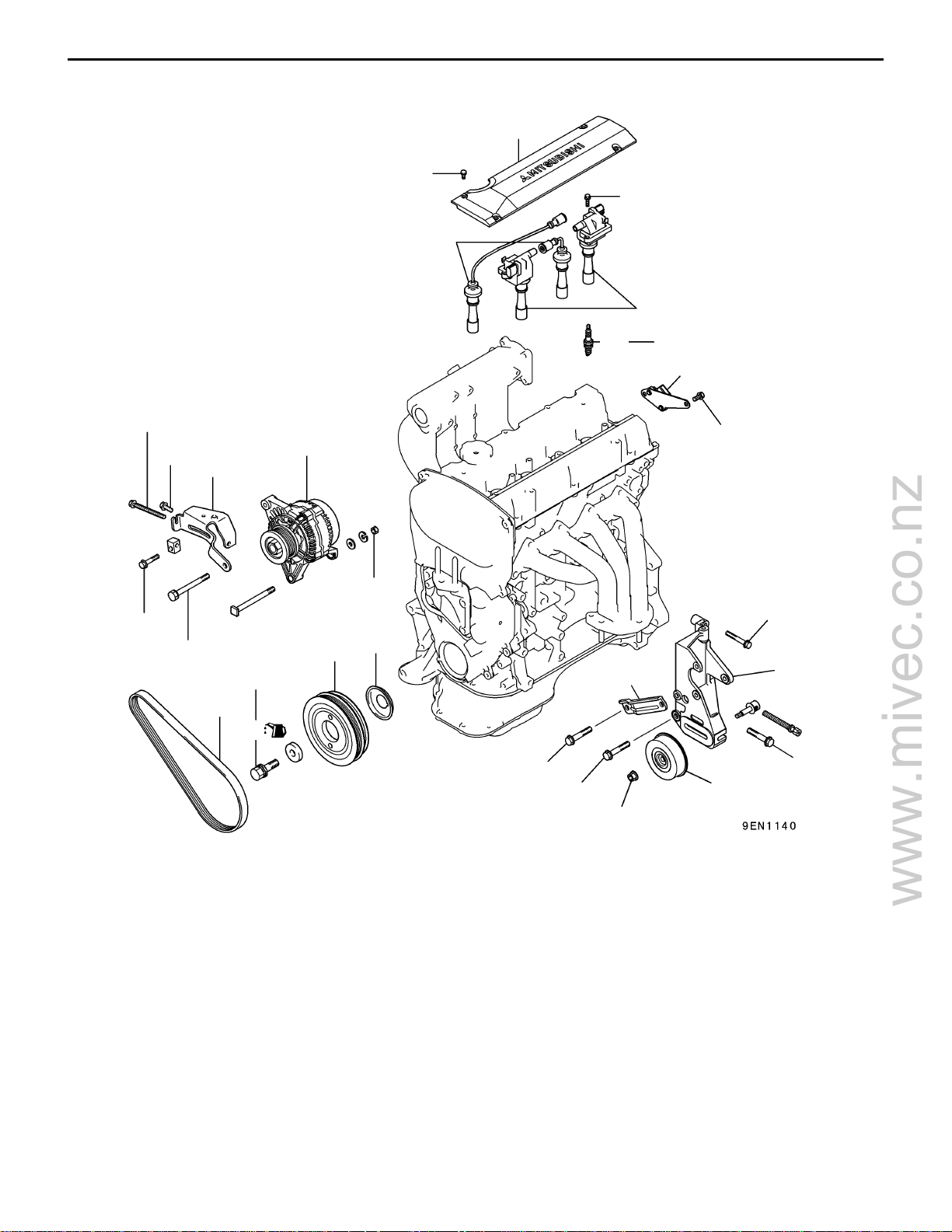
REMOVAL AND INSTALLATION <DOHC–MIVEC>
5 Nm
23 Nm
3 Nm
8
7
10 Nm
9 Nm
11
13 Nm
9
25 Nm
10
2
3
21 Nm
12
13
23 Nm
49 Nm
182 ± 4 Nm
1
4
Removal steps
1. Drive belt*
2. Alternator
3. Alternator brace
AA""BA 4. Crankshaft bolt
"BA 5. Crankshaft pulley
"BA 6. Front flange
7. Center cover
8. Spark plug cable
9. Ignition coil
44 Nm
5
21 Nm
6
15
49 Nm
44 Nm
25 Nm
10. Spark plug
11. Cam position sensor
"AA 12. Cam position sensor support
13. Cam position sensing cylinder
14. Power steering pump pulley
15. Power steering pump bracket stay
16. Power steering pump bracket
NOTE:
*: For details of adjustment, refer to the relevant model’s
chassis workshop manual.
14
16
44 Nm
E
E
Nov. 1995Mitsubishi Motors Corporation Added
Apr. 2002Mitsubishi Motors Corporation Revised
PWEE9502-A
PWEE9502-J
Page 27
www.mivec.co.nz
4G9 ENGINE (E–W) – Alternator and Ignition System
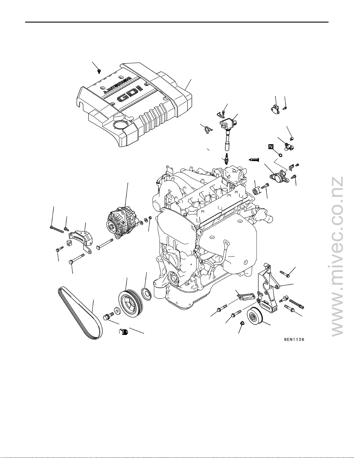
REMOVAL AND INSTALLATION
<DOHC–GDI for CARISMA, SPACE STAR, SPACE RUNNER, GALANT>
2.9 Nm
7
14
10 Nm
9
11A-3-5
5 Nm
5 Nm
23 Nm
23 Nm
49 Nm
8
9 Nm
11
25 Nm
10
12
2
13
13 Nm
21 Nm
3
44 Nm
6
21 Nm
5
16
17
1
4
182 ± 4 Nm
Removal steps
1. Drive belt*
2. Alternator
3. Alternator brace
AA""BA 4. Crankshaft bolt
"BA 5. Crankshaft pulley
"BA 6. Front flange
7. Engine cover
8. Earth strap (From 2001 model for
CARISMA, From 2001 model for
SPACE STAR)
9. Ignition coil
10. Spark plug
E
E
Nov. 1995Mitsubishi Motors Corporation
Apr. 2002Mitsubishi Motors Corporation Revised
PWEE9502-A
PWEE9502-J
49 Nm
44 Nm
25 Nm
11. Cam position sensor
"AA 12. Cam position sensor support
13. Cam position sensing cylinder
14. Ignition failure sensor (From 2001
model for CARISMA, From 2001
model for SPACE STAR)
15. Power steering pump pulley
16. Power steering pump bracket stay
17. Power steering pump bracket
NOTE:
*: For details of adjustment, refer to the relevant model’s
chassis workshop manual.
15
44 Nm
Page 28
www.mivec.co.nz
11A-3-6
4G9 ENGINE (E–W) – Alternator and Ignition System
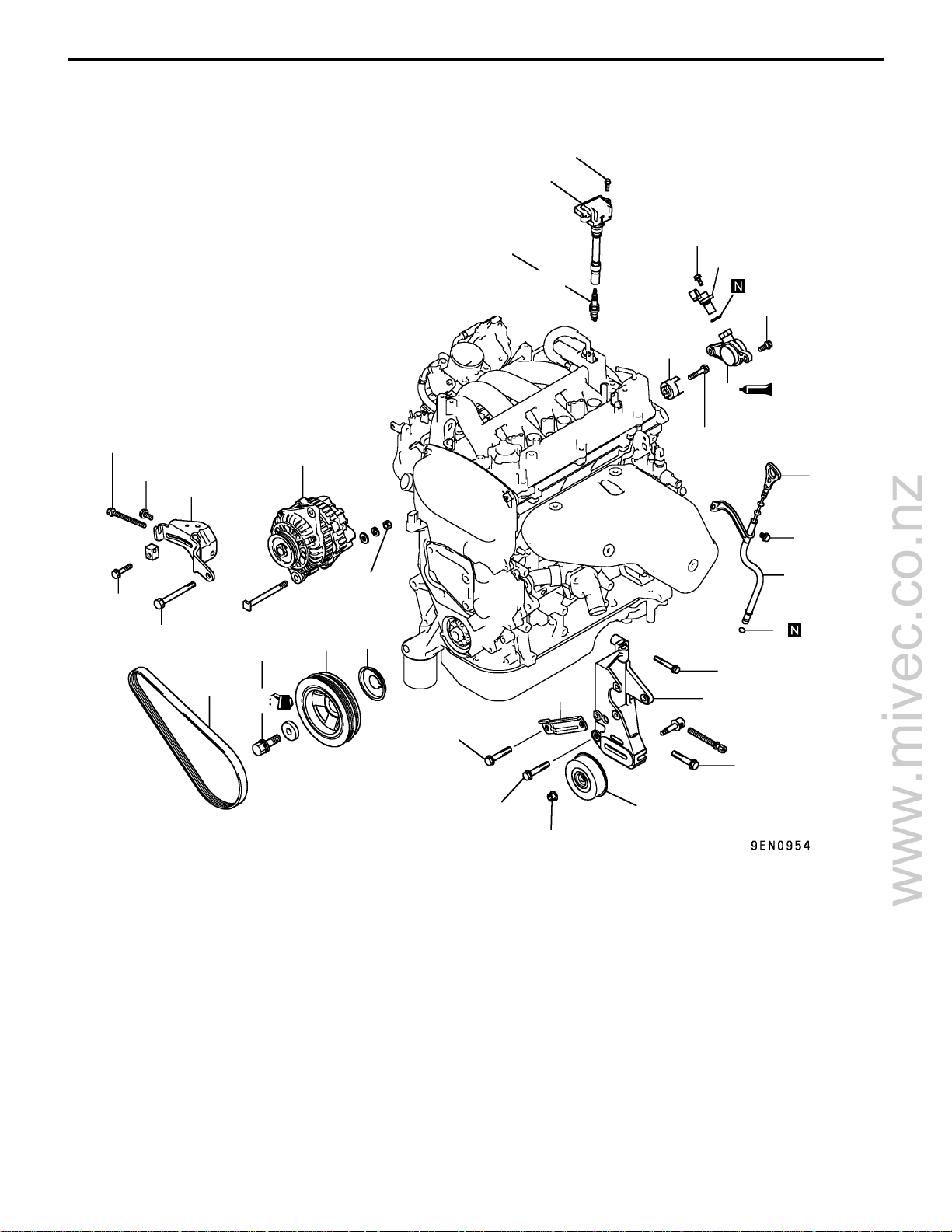
REMOVAL AND INSTALLATION <DOHC–GDI for PAJERO io>
10 Nm
13
5 Nm
23 Nm
23 Nm
44 Nm
6
3
4
182 ± 4 Nm
7
25 Nm
9 Nm
15
14
13 Nm
17
16
21 Nm
5
1
13 Nm
2
3
8
44 Nm
9
11
21 Nm
12
Removal steps
1. Oil level gauge
2. Oil level gauge guide
3. O-ring
4. Drive belt*
5. Alternator
6. Alternator brace
AA""BA 7. Crankshaft bolt
"BA 8. Crankshaft pulley
"BA 9. Front flange
49 Nm
44 Nm
44 Nm
25 Nm
"AA 16. Cam position sensor support
NOTE:
*: For details of adjustment, refer to the relevant model’s
chassis workshop manual.
10
10. Power steering pump pulley
11. Power steering pump bracket stay
12. Power steering pump bracket
13. Ignition coil
14. Spark plug
15. Cam position sensor
17. Cam position sensing cylinder
E
E
Nov. 1995Mitsubishi Motors Corporation Added
Mar . 2001Mitsubishi Motors Corporation Revised
PWEE9502-A
PWEE9502-I
Page 29
www.mivec.co.nz
MD998781
4G9 ENGINE (E–W) – Alternator and Ignition System
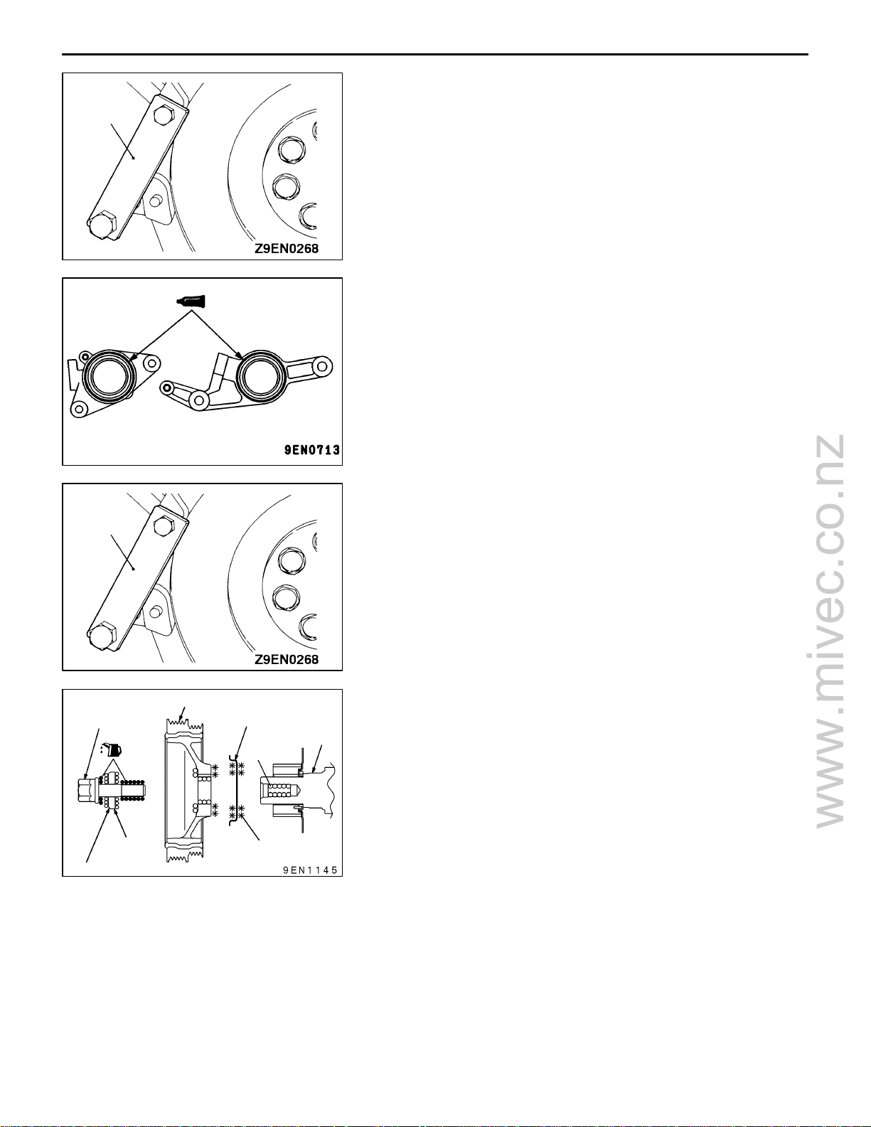
REMOVAL SERVICE POINT
AA" CRANKSHAFT BOLT REMOVAL
(1) Use the special tool to hold the flywheel or the drive
plate, and then loosen the crankshaft mounting bolts.
INSTALLATION SERVICE POINTS
"AA CAM POSITION SENSOR SUPPORT
INSTALLATION
(1) Apply a 3 mm bead of form-in-place gasket (FIPG) to
the area shown.
Specified sealant:
Mitsubishi Genuine Part No. MD970389 or
equivalent.
11A-3-7
MD998781
Crankshaft pulley
Crankshaft bolt
Washer
Big chamfered side
Front flange
Crankshaft
Clean
Degrease
"BA FRONT FLANGE / CRANKSHAFT PULLEY /
CRANKSHAFT BOLT INSTALLATION
(1) Use the special tool to hold the flywheel or the drive
plate.
(2) Clean and then degrease the front flange contacting
surface of the crankshaft pulley.
NOTE
Degreasing is necessary to prevent decrease in the friction
between contacting surfaces.
(3) Clean the bolt hole in the crankshaft, the crankshaft
contacting surface and washer contacting surface of the
crankshaft pulley, and the washer.
(4) Apply an appropriately small amount of oil to the threads
and seating surface of the crankshaft bolt.
(5) Tighten the crankshaft bolt to the specified torque of 182
± 4 Nm.
E
E
Nov. 1995Mitsubishi Motors Corporation
Jun. 2002Mitsubishi Motors Corporation Revised
PWEE9502-A
PWEE9502-K
Page 30
www.mivec.co.nz
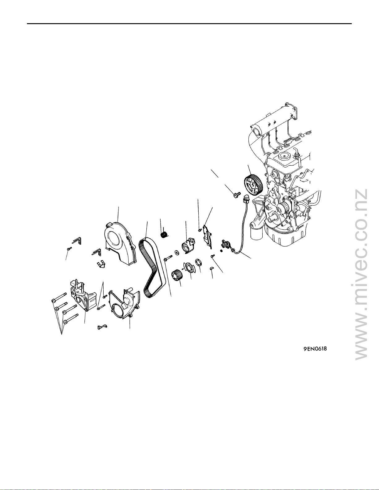
4G9 ENGINE (E–W) – Timing Belt
4. TIMING BELT
REMOVAL AND INSTALLATION <SOHC for CARISMA (Up to 1999 model),
LANCER (Except from 2001 model for Europe), GALANT>
11A-4-1
11 N m
49 Nm
88 Nm
14
13
11 N m
1
5
4
6
7
8
11 N m
10
11
9.8 Nm
12
9
23 Nm
3
2
Removal steps
1. Timing belt front upper cover
2. Timing belt front lower cover
3. Engine support bracket, right
AA""DA 4. Timing belt
"CA 5. Tensioner spring
"BA 6. Timing belt tensioner
7. Timing belt rear cover
E
Mar . 2001Mitsubishi Motors Corporation Revised
PWEE9502-I
8. Crankshaft angle sensor
(Engines without distributor)
"GA 9. Crankshaft sprocket
"GA 10. Crankshaft spacer
(Engines without distributor)
"GA 11. Crankshaft sensing blade
(Engines without distributor)
12. Crankshaft key
AB""AA 13. Camshaft sprocket bolt
14. Camshaft sprocket
Page 31

www.mivec.co.nz
11A-4-1a
4G9 ENGINE (E–W) – Timing Belt
REMOVAL AND INSTALLATION
<SOHC for CARISMA (From 2000 model), LANCER (From 2001 model for
Europe), SPACE STAR>
11 N m
11 N m
88 Nm
14
13
1
5
11 Nm
7
4
6
10
11
12
8
9.8 Nm
9
23 Nm
49 Nm
2
3
Removal steps
1. Timing belt front upper cover
2. Timing belt front lower cover
3. Engine support bracket, right
AA""DA 4. Timing belt
"CA 5. Tensioner spring
"BA 6. Timing belt tensioner
7. Timing belt rear cover
8. Crankshaft angle sensor
(Engines without distributor)
E
Apr. 2002Mitsubishi Motors Corporation Revised
PWEE9502-J
"GA 9. Crankshaft sprocket
"GA 10. Crankshaft spacer
(Engines without distributor)
"GA 11. Crankshaft sensing blade
(Engines without distributor)
12. Crankshaft key
AB""AA 13. Camshaft sprocket bolt
14. Camshaft sprocket
Page 32

www.mivec.co.nz
4G9 ENGINE (E- W) -
Timing Belt
11A-4-1b
Intentionallyblank
E
May 2000Mitsubishi Motors Corporation Added
PWEE9502-G
Page 33

www.mivec.co.nz
11A-4-2
4G9 ENGINE (E–W) – Timing Belt
REMOVAL AND INSTALLATION <SOHC for PAJERO io>
11 N m
49 Nm
88 Nm
14
13
1
23 Nm
11 N m
5
6
7
8
3
10
11
12
9.8 Nm
9
4
2
Removal steps
1. Timing belt front upper cover
2. Timing belt front lower cover
3. Accessory mount
AA""DA 4. Timing belt
"CA 5. Tensioner spring
"BA 6. Timing belt tensioner
7. Timing belt rear cover
E
Mar . 2001Mitsubishi Motors Corporation Revised
PWEE9502-I
8. Crankshaft angle sensor
"GA 9. Crankshaft sprocket
"GA 10. Crankshaft spacer
"GA 11. Crankshaft sensing blade
12. Crankshaft key
AB""AA 13. Camshaft sprocket bolt
14. Camshaft sprocket
Page 34

www.mivec.co.nz
4G9 ENGINE (E–W) – Timing Belt
REMOVAL AND INSTALLATION <DOHC>
11A-4-2a
19
11 N m
49 Nm
11 N m
3
88 Nm
4
18
17
5
24 Nm
1
6
10
36 Nm
11
11 N m
44 Nm
7
14
16
15
13
20
9
11 N m
8
13 Nm
9.8 Nm
12
2
Removal steps
1. Timing belt upper cover
2. Timing belt lower cover
3. Engine support bracket
AA""FA 4. Timing belt
5. Tensioner pulley
6. Tensioner arm
7. Shaft
"EA 8. Auto-tensioner
9. Timing belt rear cover
10. Idler pulley
E
Mar . 2001Mitsubishi Motors Corporation Revised
PWEE9502-I
11. Cam position sensor
12. Crankshaft angle sensor
"GA 13. Crankshaft sprocket
"GA 14. Crankshaft spacer
"GA 15. Crankshaft sensing blade
16. Crankshaft sprocket key
AB""AA 17. Camshaft sprocket bolt
18. Camshaft sprocket
19. Timing belt rear cover
20. Timing belt rear cover
Page 35

www.mivec.co.nz
11A-4-2b
4G9 ENGINE (E–W) – Timing Belt
REMOVAL AND INSTALLATION <DOHC–MIVEC>
18
11 N m
88 Nm
11 Nm
4
16
17
5
48 Nm
1
6
10
7
35 Nm
48 Nm
15
13
14
12
11 Nm
3
49 Nm
Removal steps
1. Timing belt front upper cover
2. Timing belt front lower cover
3. Engine support bracket, right
AA""FA 4. Timing belt
5. Tensioner pulley
6. Tensioner arm
7. Shaft
"EA 8. Auto tensioner
9. Timing belt rear cover
10. Idler pulley
2
13 Nm
8
11 Nm
19
9
9.8 Nm
11. Crankshaft angle sensor
"GA 12. Crankshaft sprocket
"GA 13. Crankshaft spacer
"GA 14. Crankshaft sensing blade
15. Crankshaft key
AB""AA 16. Camshaft sprocket bolt
17. Camshaft sprocket
18. Timing belt rear cover
19. Timing belt rear cover
11
E
Mar . 2001Mitsubishi Motors Corporation Revised
PWEE9502-I
Page 36

www.mivec.co.nz
4G9 ENGINE (E–W) – Timing Belt
REMOVAL AND INSTALLATION
<DOHC–GDI for CARISMA, SPACE STAR, SPACE RUNNER>
21
11 Nm
11 Nm
4
11A-4-2c
19
49 Nm
11 Nm
3
88 Nm
17
1
48 Nm
5
48 Nm
6
9
7
35 Nm
18
10
13
12
15
14
11 Nm
16
20
8
11 Nm
13 Nm
2
12
9.8 Nm
9.8 Nm
11
Removal steps
1. Timing belt front upper cover
2. Timing belt front lower cover
3. Engine support bracket, right
AA""FA 4. Timing belt
5. Tensioner pulley
6. Tensioner arm
7. Shaft
"EA 8. Auto tensioner
9. Timing belt rear cover
10. Idler pulley
11. Crankshaft angle sensor
(Up to 1999 model)
12. Crankshaft angle sensor
(From 2000 model)
E
Mar . 2001Mitsubishi Motors Corporation Revised
PWEE9502-I
"GA 13. Crankshaft sprocket
"GA 14. Crankshaft spacer
"GA 15. Crankshaft sensing blade
16. Crankshaft key
AB""AA 17. Camshaft sprocket bolt
18. Camshaft sprocket
19. Timing belt rear cover
(Up to 2000 model)
20. Timing belt rear cover
(Up to 2000 model)
21. Timing belt rear upper cover
(From 2001 model)
Page 37

www.mivec.co.nz
11A-4-2d
4G9 ENGINE (E–W) – Timing Belt
REMOVAL AND INSTALLATION <DOHC–GDI for GALANT>
18
11 Nm
4
49 Nm
11 Nm
3
88 Nm
17
16
1
48 Nm
5
48 Nm
6
7
35 Nm
10
14
13
15
12
9
8
13 Nm
11 Nm
9.8 Nm
11
2
Removal steps
1. Timing belt front upper cover
2. Timing belt front lower cover
3. Engine support bracket, right
AA""FA 4. Timing belt
5. Tensioner pulley
6. Tensioner arm
7. Shaft
"EA 8. Auto tensioner
9. Timing belt rear cover
E
Mar . 2001Mitsubishi Motors Corporation Revised
PWEE9502-I
10. Idler pulley
11. Crankshaft angle sensor
"GA 12. Crankshaft sprocket
"GA 13. Crankshaft spacer
"GA 14. Crankshaft sensing blade
15. Crankshaft key
AB""AA 16. Camshaft sprocket bolt
17. Camshaft sprocket
18. Timing belt rear upper cover
Page 38

www.mivec.co.nz
4G9 ENGINE (E–W) – Timing Belt
REMOVAL AND INSTALLATION <DOHC–GDI for PAJERO io>
21
11 Nm
19
11 Nm
4
88 Nm
17
18
11A-4-2e
49 Nm
11 N m
5
1
48 Nm
6
10
7
15
20
14
35 Nm
48 Nm
16
12
13
11 Nm
11 Nm
9
9.8 Nm
11
11 Nm
8
3
13 Nm
2
Removal steps
1. Timing belt front upper cover
2. Timing belt front lower cover
3. Accesory mount
AA""FA 4. Timing belt
5. Tensioner pulley
6. Tensioner arm
7. Shaft
"EA 8. Auto tensioner
9. Timing belt rear cover
10. Idler pulley
E
Mar . 2001Mitsubishi Motors Corporation Revised
PWEE9502-I
11. Bracket
12. Crankshaft angle sensor
"GA 13. Crankshaft sprocket
"GA 14. Crankshaft spacer
"GA 15. Crankshaft sensing blade
16. Crankshaft key
AB""AA 17. Camshaft sprocket bolt
18. Camshaft sprocket
19. Timing belt rear cover <4G93>
20. Timing belt rear cover <4G93>
21. Timing belt rear upper cover
<4G94>
Page 39

www.mivec.co.nz
11A-4-2f
4G9 ENGINE (E- W) -
Timing Belt
Intentionallyblank
E
May 2000Mitsubishi Motors Corporation Added
PWEE9502-G
Page 40

www.mivec.co.nz
4G9 ENGINE (E-W) -
REMOVAL SERVICE POINTS
AA"
(1) Mark belt running direction for reinstallation.
TIMING BELT REMOVAL
Timing Belt
11A-4-3
MD998719
or
MD998754
MB990767
AB"
<With rocker cover removed> (Except SOHC)
(1) Use a wrench to hold the hexagonal part of the camshaft,
CAMSHAFT SPROCKET BOLT REMOVAL
and then remove the camshaft sprocket mounting bolt.
INSTALLATION SERVICE POINTS
MD998719
or
MD998754
E
MB990767
Nov. 1995Mitsubishi Motors Corporation Revised
"AA
PWEE9502-A
CAMSHAFT SPROCKET BOLT INSTALLATION
Page 41

www.mivec.co.nz
11A-4-4
4G9 ENGINE (E-W) -
Timing belt
Exhaust
side
“A”
Pliers
Tensioner
pulley fixing
bolt
Tensioner
“B”
"BA
TIMING BELT TENSIONER INSTALLATION
(1) Let the pulley of the timing belt tensioner comr closest
to the exhaust side. Temporarily tighten the tensioner
pulley fixing bolt.
"CA
TENSIONER SPRING INSTALLATION
(1) Insert the tip A (shorter one) of the tensioner spring into
the oil pump case.
(2) Use pliers or similar tool to pinch the tip B (longer one),
and then hook it to the tensioner bracket arm.
"DA
TIMING BELT INSTALLATION
(1) Turn the crankshaft sprocket by three teeth from the timing
mark.
Caution
Aligning the timing marks positions the piston to the
topdead centre. Then, if the camshaftturns,thevalves
may hit and damage the pistons.
Timing mark
Timing marks
E
(2) Check that the timing belt tensioner and tensioner spring
are installed correctly. (Refer to the service points B and
C.)
(3) Align the timing marks on the camshaft sprocket to that
on the cylinder head.
(4) Align the timing mark on the crankshaft sprocket to that
on the oil pump case.
(5) Place the timing belt over t he sprocket according in the
following order.
1. Crankshaft sprocket
2. Water pump sprocket
3. Camshaft sprocket
4. Tension pulley
May 1995Mitsubishi Motors Corporation
PWEE9502
Page 42

www.mivec.co.nz
MD998716
4G9 ENGINE (E-W) -
(6) Slightly loosen the tensioner pulley fixing bolt which is
tightened temporarily to tighten the belt by a force of
the tensioner spring.
(7) Turn th e crankshaft clockwise by two turns.
(8) Check that the timing marks are aligned.
(9) Tighten the fixing bolt of the tensioner pulley.
Timing Belt
11A-4-5
Set hole (A)
Set hole (B)
"EA
(1) If the auto-tensioner rod is fully extended, set it in the
(2) Install the auto-tensioner
AUTO-TENSIONER INSTALLATION
retracted position with the following procedure.
1) Hold the auto-tensioner in a vice, being careful not
to tilt it.
2) Slowly close the vice to force the rod in to align hole
(A) of the rod with the set hole (B).
3) Insert a 2.0-mm-Allen key in diameter or similar into
the set holes.
4) Remove the auto-tensioner from the vice.
Leave the align key until installation of the timing belt
is completed.
E
Nov. 1995Mitsubishi Motors Corporation Revised
PWEE9502-A
Page 43

www.mivec.co.nz
11A-4-6
4G9 ENGINE (E-W) -
Timing Belt
Timing mark
Timing marks
Paper clip
"FA
(1) Make sure that the auto-tensioner is installed properly.
(2) Align the timing mark on each sprocket with the
(3) Turn the crankshaft sprocket one half the tooth width
(4) Fit t he timing belt to the intake camshaft sprocket and
TIMING BELT INSTALLATION
(Refer to service point F.)
corresponding mark on the timing belt.
counterclockwise.
secure with a paper clip at the illustrated position.
Timing mark
Timing mark
E
Nov. 1995Mitsubishi Motors Corporation Revised
(5) Use two wrenches to fit the timing belt to the exhaust
sprocket while aligning the timing marks.
PWEE9502-A
Page 44

www.mivec.co.nz
4G9 ENGINE (E-W) -
(6) Secure the timing belt with a paper clip at the illustrated
position.
(7) Fit the belt to the idler pulley water pump sprocket,
crankshaft sprocket and tensioner pulley in that order.
Idler pulley
Water
pump
sprocket
Timing Belt
11A-4-7
Tensioner
pulley
Crankshaft sprocket
(8) Raise the tensioner pulley in the direction of an arrow
and tighten the tensioner pulley bolt.
(9) Remove the two paper clips.
(10)Make sure that all timing marks are in alignment.
(11)Give a 1/4 counterclockwise turn to the crankshaft. Then
turn the crankshaft clockwise to align the timing marks
again.
E
May 1995Mitsubishi Motors Corporation
PWEE9502
Page 45

www.mivec.co.nz
11A-4-8
MD998767
4G9 ENGINE (E–W) – Timing Belt
(12)Install the special tool and a torque wrench to the tensioner
pulley.
(13)Using torque wrench, torque to 2.6 Nm.
(14)While holding the tensioner pulley to prevent it from
turning, tighten the center bolt to the specified torque.
(15)Give two clockwise turns to the crankshaft and leave
as it is for approx. 15 minutes.
(16)Check if the Allen wrench inserted during installation of
the auto-tensioner can be pulled out lightly. If it can be
pulled out lightly , the belt is properly tensioned. Therefore,
pull out the wrench. The belt is also properly tensioned
if the auto-tensioner projection is of standard value.
Standard value: 3.8 – 4.5 mm
(17)If the wrench cannot be pulled out lightly, repeat the steps
(12) through (15) to obtain appropriate belt tension.
NOTE
Check the tightening torque of the crankshaft bolt always
after rotating the crankshaft counterclockwise using the
crankshaft bolt. Retighten the bolt if the tightening torque
is not up to specification.
Crankshaft
sprocket
Clean
Crankshaft sensing blade
Crankshaft
Crankshaft spacer
Degrease
Oil pump case
"GA CRANKSHAFT SENSING BLADE / CRANKSHAFT
SPACER / CRANKSHAFT SPROCKET
INSTALLATION
(1) Clean and then degrease the following surfaces and parts:
front surface of oil pump case, sprocket mounting surface
of crankshaft, crankshaft spacer, crankshaft sensing
blade, and crankshaft sprocket.
NOTE
Degreasing is necessary to prevent decrease in the friction
between contacting surfaces.
(2) Clean the crankshaft contacting surface of the crankshaft
sprocket.
INSPECTION 11300200077
TIMING BELT
Replace belt if any of the following conditions exist.
(1) Hardening of back rubber.
Back side is glossy without resilience and leaves no indent
when pressed with fingernail.
(2) Cracks on rubber back.
Cracks
(3) Cracks or peeling of canvas.
(4) Cracks on tooth bottom.
(5) Cracks on belt sides.
Peeling
Cracks
Cracks
E
E
May 1995Mitsubishi Motors Corporation
Mar . 2001Mitsubishi Motors Corporation Revised
PWEE9502
PWEE9502-I
Page 46

www.mivec.co.nz
Rounded edge
Abnormal wear
(Fluffy strand)
Rubber exposed
Tooth missing
and canvas
fiber exposed
4G9 ENGINE (E-W) -
(6) Abnormal wear of belt sides. The sides are normal if
they are sharp as if cut by a knife.
(7) Abnormal wear on teeth.
(8) Missing tooth.
Timing Belt
11A-4-9
98 to 196 N
11 mm
Stroke
TENSIONER PULLER, IDLER PULLEY
(1) Check the pulley for smooth rotation, excessive play,
abnormal noise. Replace it if necessary.
AUTO-TENSIONER
(1) Check the tensioner for oil leaks. Replace it if necessary.
(2) Check the rod end for wear or damage. Replace the
tensioner if necessary.
(3) Measure the rod projection length. If not within the
standard value, replace the tensioner.
Standard value: 11 mm
(4) Press the rod by a force of 98 to 196 N and measure
the rod stroke. If not within the standard value, replace
the tensioner.
Standard value: 1 mm or less
E
May 1995Mitsubishi Motors Corporation
PWEE9502
Page 47

www.mivec.co.nz
4G9 ENGINE (E-W) -
Fuel and Emission Control System
5. FUEL AND EMISSION CONTROL SYSTEM
REMOVAL AND INSTALLATION <SOHC-CARBURETOR>
11A-5-1
3
2
21 Nm
18 Nm
17 Nm
8
4
9
5
6
7
1
21 Nm
10
11
Removal steps
1. Breather tube
2. Fuel hose
3. Fuel hose
4. Fuel pump
5. Gasket
6. Insulator
7. Gasket
8. Carburetor
9. Gasket
10. EGR valve
11. Gasket
E
Nov. 1996Mitsubishi Motors Corporation
PWEE9502-B
Revised
Page 48

www.mivec.co.nz
11A-5-2
4G9 ENGINE (E–W) – Fuel and Emission Control System
REMOVAL AND INSTALLATION <SOHC–MPI for other than PAJERO io>
12 Nm
9 Nm
10
16
17
19 Nm
2
15
13
14
12
Engine with solenoid valve Flange
Engine with solenoid valve Washer
Engine without solenoid valve
1
11 N m
9 Nm
10Nm
3
19
21
21 Nm
11
7
24 Nm
4
20
6
12 Nm
9
8
9 Nm
Removal steps
1. Vacuum hose and pipe assembly
2. Throttle body
"CA 3. Gasket
4. Engine hanger (4G94)
5. Throttle body stay (4G94)
6. Vacuum hose
7. Fuel hose
"BA 8. Fuel pressure regulator
9. O-ring
10. Delivery pipe and injector
11. Insulator
12. Insulator
5
18
9 Nm
"AA 13. Injector
14. O-ring
15. Grommet
16. Delivery pipe
17. Fuel return pipe
18. Solenoid valve assembly
(Engine with solenoid valve)
19. EGR valve
(Engine with EGR valve)
20. Cover
(Engine without EGR valve)
21. Gasket
Mar . 2001Mitsubishi Motors Corporation Revised
E
E
Nov. 1996Mitsubishi Motors Corporation Revised
PWEE9502-I
PWEE9502-B
Page 49

www.mivec.co.nz
4G9 ENGINE (E–W) – Fuel and Emission Control System
REMOVAL AND INSTALLATION <SOHC–MPI for PAJERO io>
9 Nm
12 Nm
8
18
24 Nm
11A-5-3
17
1
19 Nm
11
3
15
16
14
5
11 N m
6
13
2
12
22 Nm
20
9 Nm
4
21
7
9
19
9 Nm
10
9 Nm
Removal steps
1. Stay (From 2002 model)
2. Harness bracket
3. Throttle cable bracket
4. Vacuum hose and pipe assembly
5. Throttle body
"CA 6. Gasket
7. Vacuum hose
8. Fuel hose
"BA 9. Fuel pressure regulator
10. O-ring
11. Delivery pipe and injector
E
E
Nov. 1996Mitsubishi Motors Corporation
Jun. 2002Mitsubishi Motors Corporation Revised
PWEE9502-B
PWEE9502-K
12. Insulator
13. Insulator
"AA 14. Injector
15. O-ring
16. Grommet
17. Delivery pipe
18. Fuel return pipe
19. Solenoid valve assembly
20. EGR valve
21. Gasket
Revised
Page 50

www.mivec.co.nz
11A-5-4
4G9 ENGINE (E–W) – Fuel and Emission Control System
REMOVAL AND INSTALLATION <DOHC>
11 N m
15
14
12
13
11
1
10
9 Nm
6
9
10 Nm
17
3
9 Nm
2
23 Nm
16
4
23 Nm
18 Nm
8
7
9 Nm
Removal steps
1. Vacuum pipe assembly
2. Throttle body assembly
"CA 3. Gasket
4. Throttle body stay (MIVEC)
5. Vacuum hose
6. Fuel hose
"BA 7. Fuel pressure regulator
8. O-ring
9. Delivery pipe and injector
5
10. Insulator
11. Insulator
"AA 12. Injector
13. O-ring
14. Grommet
15. Delivery pipe
16. Fuel return pipe
17. Solenoid valve
E
E
Nov. 1996Mitsubishi Motors Corporation
Jun. 2002Mitsubishi Motors Corporation Revised
PWEE9502-B
PWEE9502-K
Revised
Page 51

www.mivec.co.nz
4G9 ENGINE (E-W) -
Fuel and Emission Control System
INSTALLATION SERVICE POINTS
"AA
(1) Apply a small amount of new engine oil to the O-ring.
(2) While turning the injector to the left and right, install it
(3) Check that the injector turns smoothly. If it does not turn
Injector connector
AB
Delivery pipe
(4) Check that the clearance between the injector connector
11A-5-5
INJECTORS INSTALLATION
Caution
Be sure not to let engine oil get into the delivery
pipe.
to t he delivery pipe.
smoothly, the O-ring may be trapped. Remove the injector
and check the O-ring for damage, and then re-insert it
into the delivery pipe and check once again.
and the delivery pipe is uniform (A = B).
<SOHC-MPI for other
than PAJERO io>
Projection
"BA
(1) Apply a small amount of new engine oil to the O-ring.
(2) Check that the fuel pressure regulator turns smoothly.
"CA
(1) Position the projection as shown in the illustration.
FUEL PRESSURE REGULATOR INSTALLATION
Insert the fuel pressure regulator into the delivery pipe
being careful not to damage the O-ring.
Caution
Be sure not to let engine oil get into the delivery
pipe.
If it does not turn smoothly, the O-ring may be trapped.
Remove the fuel pressure regulator and check the O-ring
for damage, and then re-insert it into the delivery pipe
and check once again.
GASKET INSTALLATION
E
Dec. 1998Mitsubishi Motors Corporation Added
PWEE9502-E
Page 52

www.mivec.co.nz
11A-5-6
<SOHC-MPI
forPAJEROio>
Projection
4G9 ENGINE (E-W) -
Fuel and Emission Control System
E
Dec. 1998Mitsubishi Motors Corporation Added
PWEE9502-E
Page 53

www.mivec.co.nz
4G9 ENGINE (E- W) -
Throttle Body and EGR System (GDI)
11A-5a-1
5a. THROTTLE BODY AND EGR SYSTEM (GDI)
REMOVAL AND INSTALLATION <Up to 2000 model for CARISMA, 1999 model for
SPACE STAR, SPACE RUNNER>
18 Nm
6
7
18 Nm
32
9Nm
18 Nm
14
13
18 Nm
12
24 Nm
17
11
4
15
16
9Nm
14
8
30 Nm
1
10
18 Nm
5
9
Removal steps
1. Air intake plenum resonator
2. O-ring
"BA
"AA
E
3. Intake manifold stay
4. Water hose
5. Water hose (Up to 1998 model for
CARISMA, SPACE RUNNER)
6. Throttle body
7. Throttle body gasket
8. Ignition harness
9. Water hose
10. EGR valve
11. EGR valve gasket
May 2000Mitsubishi Motors Corporation Revised
PWEE9502-G
12. Engine hanger
13. EGR valve support
14. Gasket
15. Water hose (Up to 1998 model for
CARISMA, SPACE RUNNER)
16. Air by-pass valve
(Up to 1998 model for CARISMA,
SPACE RUNNER)
17. Air by-pass valve gasket
(Up to 1998 model for CARISMA,
SPACE RUNNER)
Page 54

www.mivec.co.nz
11A-5a-2
4G9 ENGINE (E–W) – Throttle Body and EGR System (GDI)
REMOVAL AND INSTALLATION
<From 2001 model for CARISMA, SPACE STAR and GALANT>
20 Nm
24 Nm
10
18 Nm
2
6
7
3
24 Nm
5
8
12
4
11
12
30 Nm
9
24 Nm
18 Nm
1
Removal steps
"BA 1. Intake manifold stay (For GALANT)
2. Water hose
3. Water hose
4. Water hose
5. Throttle body stay
6. Throttle body
E
Apr. 2003Mitsubishi Motors Corporation Revised
PWEE9502-L
"AA 7. Throttle body gasket
8. Ignition harness
9. Water hose
10. EGR valve
11. EGR valve support
12. Gasket
Page 55

www.mivec.co.nz
4G9 ENGINE (E- W) -
Throttle Body and EGR System (GDI)
REMOVAL AND INSTALLATION <For PAJERO io - 4G93>
1
18 Nm
9
14
11A-5a-3
18 Nm
2
8
11 Nm
10
18 Nm
15
13
23 Nm
7
11 Nm
14
12
3
16
11
5
13 Nm
6
18 Nm
4
Removal steps
1. Water hose
2. Water hose
3. Water hose
4. Water hose
5. Water hose
6. Water hose clamp
7. Water pipe
8. Water pipe
E
July 2000Mitsubishi Motors Corporation Revised
PWEE9502-H
"AA
9. Throttle body
10. Throttle body gasket
11. EGR valve
12. EGR valve gasket
13. EGR valve support
14. Gasket
15. Engine hanger
Page 56

www.mivec.co.nz
11A-5a-4
4G9 ENGINE (E- W) -
Throttle Body and EGR System (GDI)
REMOVAL AND INSTALLATION <For PAJERO io - 4G94>
1
18 Nm
15
18 Nm
2
18 Nm
11
8
18 Nm
16
10
14
23 Nm
11 Nm
14
7
9
3
13
12
13 Nm
6
5
18 Nm
11 Nm
Removal steps
1. Water hose
2. Water hose
3. Water hose
4. Water hose
5. Water hose
6. Water hose clamp
7. Water pipe
8. Water pipe
4
9. Throttle body stay
10. Throttle body
"AA
11. Throttle body gasket
12. EGR valve
13. EGR valve gasket
14. EGR valve support
15. Gasket
16. Engine hanger
E
July 2000Mitsubishi Motors Corporation Revised
PWEE9502-H
Page 57

www.mivec.co.nz
4G9 ENGINE (E- W) -
Throttle Body and EGR System (GDI)
11A-5a-5
<Up to 2000 model for
CARISMA,1999model
for SPACE STAR,
SPACE RUNNER>
<From 2001 model for CARISMA,
From 2001 model for SPACE STAR,
GALANT>
Tab
INSTALLATION SERVICE POINTS
"AA
THROTTLE BODY GASKET
<PAJERO io>
<Up to 2000 model>
Bolt
Intake
manifold
stay
Cylinder block
<From 2001 model>
Bolt
Intake manifold
Intake manifold
"BA
INTAKE MANIFOLD STAY INSTALLATION
(1) Tighten the four bolts at the top and bottom of the stay
handtight.
(2) Check that the stay seating surface is in close contact
with the bosses on the intake manifold and the cylinder
block.
(3) Tighten the four bolts to the specified torque.
Cylinder
block
Bolt
Intake manifold
stay
Bolt
E
July 2000Mitsubishi Motors Corporation Added
PWEE9502-H
Page 58

www.mivec.co.nz
4G9 ENGINE (E–W) – Intake and Exhaust Manifold
6. INTAKE AND EXHAUST MANIFOLD
REMOVAL AND INSTALLATION <SOHC–CARBURETOR>
20 Nm
11A-6-1
20 Nm
2
3
5
4
9
7
Bolt with head mark “4”
Bolt with head mark “7”
13
14 Nm
29 Nm
6
12 Nm
19 Nm
12
18 Nm
13 Nm
8
31 Nm
1
11
Bolt with head mark “4”
Bolt with head mark “7”
Removal steps
1. Engine hanger
"BA 2. Intake manifold stay
3. Intake manifold
4. Intake manifold gasket
5. Oil level gauge
6. Oil level gauge guide
12 Nm
19 Nm
10
13 Nm
19 Nm
7. O-ring
8. Exhaust manifold cover
9. Engine hanger
"AA 10. Exhaust manifold bracket A
"AA 11. Exhaust manifold bracket B
12. Exhaust manifold
13. Exhaust manifold gasket
E
E
Nov. 1996Mitsubishi Motors Corporation
Mar . 2001Mitsubishi Motors Corporation Revised
PWEE9502-B
PWEE9502-I
Revised
Page 59

www.mivec.co.nz
11A-6-2
4G9 ENGINE (E–W) – Intake and Exhaust Manifold
REMOVAL AND INSTALLATION <SOHC–MPI–FRONT WHEEL DRIVE (4G92 and
4G93–Except from 2001 model for Europe)>
20 Nm
20 Nm
31 Nm
Bolt with head mark “4”
Bolt with head mark “7”
3
1
4
2
12 Nm
19 Nm
7
13
5
6
14 Nm
29 Nm
18 Nm
12
Bolt with head mark “4”
Bolt with head mark “7”
Removal steps
1. Engine hanger
2. Intake manifold stay
3. Intake manifold
4. Intake manifold gasket
5. Oil level gauge
6. Oil level gauge guide
11
10
9
19 Nm
12 Nm
19 Nm
7. O-ring
8. Exhaust manifold cover
9. Engine hanger
"AA 10. Exhaust manifold bracket A
"AA 11. Exhaust manifold bracket B
12. Exhaust manifold
13. Exhaust manifold gasket
8
13 Nm
Nov. 1996Mitsubishi Motors Corporation Revised
E
E
Mar . 2001Mitsubishi Motors Corporation Revised
PWEE9502-B
PWEE9502-I
Page 60

www.mivec.co.nz
4G9 ENGINE (E–W) – Intake and Exhaust Manifold
11A-6-2a
REMOVAL AND INSTALLATION <SOHC–MPI–FRONT WHEEL DRIVE (4G92 and
4G93–From 2001 model for Europe)>
20 Nm
20 Nm
31 Nm
3
19 Nm
1
4
7
14 Nm
13
2
30 Nm
12
5
6
8
44 Nm
18 Nm
13 Nm
10
Removal steps
1. Engine hanger
2. Intake manifold stay
3. Intake manifold
4. Intake manifold gasket
5. Oil level gauge
6. Oil level gauge guide
7. O-ring
14
9
19 Nm
11
19 Nm
13 Nm
35 Nm
8. Oxygen sensor
9. Engine hanger
10. Exhaust manifold cover
11. Exhaust manifold bracket B
12. Exhaust manifold
13. Exhaust manifold gasket
14. Exhaust manifold bracket A
E
E
Nov. 1996Mitsubishi Motors Corporation
Mar . 2001Mitsubishi Motors Corporation Revised
PWEE9502-B
PWEE9502-I
Revised
Page 61

www.mivec.co.nz
11A-6-2b
4G9 ENGINE (E–W) – Intake and Exhaust Manifold
REMOVAL AND INSTALLATION <SOHC–MPI–FRONT WHEEL DRIVE (4G94)>
20 Nm
2
20 Nm
31 Nm
3
4
5
6
14 Nm
12
1
11
29 Nm
18 Nm
10
9
7
8
19 Nm
13 Nm
19 Nm
Removal steps
1. Intake manifold stay
2. Intake manifold
3. Intake manifold gasket
4. Oil level gauge
5. Oil level gauge guide
6. O-ring
Nov. 1996Mitsubishi Motors Corporation Revised
E
E
Mar . 2001Mitsubishi Motors Corporation Revised
PWEE9502-B
PWEE9502-I
"AA 9. Exhaust manifold bracket A
"AA 10. Exhaust manifold bracket B
7. Exhaust manifold cover
8. Engine hanger
11. Exhaust manifold
12. Exhaust manifold gasket
Page 62

www.mivec.co.nz
4G9 ENGINE (E–W) – Intake and Exhaust Manifold
11A-6-2c
REMOVAL AND INSTALLATION
<SOHC–MPI – REAR WHEEL DRIVE (4G93 – Except from 2002 model for
Europe)>
6
4
19 Nm
31 Nm
20 Nm
8
13 Nm
7
12
13 Nm
5
11
9
18 Nm
1
10
35 Nm
29 Nm
2
14 Nm
3
Removal steps
1. Oil level gauge
2. Oil level gauge guide
3. O-ring
4. Engine hanger
5. Intake manifold stay
6. Intake manifold
E
E
Nov. 1996Mitsubishi Motors Corporation
Jun. 2002Mitsubishi Motors Corporation Revised
PWEE9502-B
PWEE9502-K
"AA 10. Exhaust manifold bracket
7. Intake manifold gasket
8. Exhaust manifold cover
9. Engine hanger
11. Exhaust manifold
12. Exhaust manifold gasket
Revised
Page 63

www.mivec.co.nz
11A-6-2d
4G9 ENGINE (E–W) – Intake and Exhaust Manifold
REMOVAL AND INSTALLATION
<SOHC–MPI – REAR WHEEL DRIVE (4G93 – from 2002 model for Europe)>
20 Nm
8
13 Nm
7
6
4
5
12
11
13 Nm
9
19 Nm
18 Nm
35 Nm
1
31 Nm
Removal steps
1. Oil level gauge
2. Oil level gauge guide
3. O-ring
4. Engine hanger
5. Intake manifold stay
6. Intake manifold
1
29 Nm
10
2
14 Nm
3
7. Intake manifold gasket
8. Exhaust manifold cover
9. Engine hanger
"AA 10. Exhaust manifold bracket
11. Exhaust manifold
12. Exhaust manifold gasket
E
E
Nov. 1996Mitsubishi Motors Corporation
Jun. 2002Mitsubishi Motors Corporation Revised
PWEE9502-B
PWEE9502-K
Revised
Page 64

www.mivec.co.nz
4G9 ENGINE (E–W) – Intake and Exhaust Manifold
11A-6-2e
REMOVAL AND INSTALLATION <SOHC–MPI – REAR WHEEL DRIVE (4G94)>
6
4
19 Nm
31 Nm
8
20 Nm
13 Nm
7
13 Nm
12
5
11
9
18 Nm
1
29 Nm
10
Removal steps
1. Oil level gauge
2. Oil level gauge guide
3. O-ring
4. Engine hanger
5. Intake manifold stay
6. Intake manifold
98 Nm
2
14 Nm
3
7. Intake manifold gasket
8. Exhaust manifold cover
9. Engine hanger
"AA 10. Exhaust manifold bracket
11. Exhaust manifold
12. Exhaust manifold gasket
E
E
Nov. 1996Mitsubishi Motors Corporation
Jun. 2002Mitsubishi Motors Corporation Added
PWEE9502-B
PWEE9502-K
Revised
Page 65

www.mivec.co.nz
11A-6-2f
4G9 ENGINE (E–W) – Intake and Exhaust Manifold
Intentionally blank
E
E
Nov. 1996Mitsubishi Motors Corporation
Jun. 2002Mitsubishi Motors Corporation Added
PWEE9502-B
PWEE9502-K
Revised
Page 66

www.mivec.co.nz
4G9 ENGINE (E–W) – Intake and Exhaust Manifold
REMOVAL AND INSTALLATION <DOHC>
20 Nm
Bolt with head mark “4”
Bolt with head mark “7”
3
1
20 Nm
4
2
11A-6-3
12 Nm
19 Nm
12
11
29 Nm
31 Nm
Removal steps
1. Engine hanger
2. Intake manifold stay
3. Intake manifold
4. Intake manifold gasket
5. Oil level gauge
6. Oil level gauge guide
18 Nm
Bolt with head mark “4”
Bolt with head mark “7”
12 Nm
19 Nm
5
8
10
6
9
7
19 Nm
7. O-ring
8. Engine hanger
"AA 9. Exhaust manifold bracket A
"AA 10. Exhaust manifold bracket B
11. Exhaust manifold
12. Exhaust manifold gasket
14 Nm
E
E
Mar . 2001Mitsubishi Motors Corporation Revised
Nov. 1996Mitsubishi Motors Corporation
PWEE9502-I
PWEE9502-B
Revised
Page 67

www.mivec.co.nz
11A-6-4
Bracket A
Exhaust
manifold
Exhaust
manifold
Bracket
4G9 ENGINE (E–W) – Intake and Exhaust Manifold
INSTALLATION SERVICE POINT
Bracket B
"AA EXHAUST MANIFOLD BRACKET INSTALLATION
<FRONT WHEEL DRIVE>
(1) Install temporarily the exhaust manifold brackets A and
B as shown in the illustration.
(2) Check that both brackets are in close contact with the
bosses, and then tighten fully the bracket mounting bolts.
<REAR WHEEL DRIVE>
(1) T emporarily install the exhaust manifold bracket as shown
in the illustration.
(2) Verify that the bracket is brought into close contact with
the boss on the exhaust manifold, then tighten the bolts
to the specified torque.
Intake
manifold
“UP” mark
Intake
manifold
stay
Cylinder block
"BA INTAKE MANIFOLD STAY INSTALLATION
<FRONT WHEEL DRIVE>
(1) Check to ensure that the intake manifold stay is in close
contact with the intake manifold and the cylider block
before tightening the respective mounting bolts to the
specified torque.
<REAR WHEEL DRIVE>
(1) Install the intake manifold stay with its “UP” mark directed
toward the intake manifold.
E
E
Nov. 1996Mitsubishi Motors Corporation
Mar . 2001Mitsubishi Motors Corporation Revised
PWEE9502-B
PWEE9502-I
Added
Page 68

www.mivec.co.nz
4G9 ENGINE (E- W) -
Intake Manifold (GDI)
11A-6a-1
6a. INTAKE MANIFOLD (GDI)
REMOVAL AND INSTALLATION <Up to 2000 model for CARISMA, 1999 model for
SPACE STAR, SPACE RUNNER>
1
11 Nm
9Nm
6
8
11 Nm
11 Nm
5
2
19 Nm
3
9Nm
4
7
9
10
19 Nm
Removal steps
1. Air by-pass hose
(Up to 1998 model for CARISMA,
SPACE RUNNER)
2. Vacuum pipe and hose
3. Bracket
4. Solenoid valve
E
E
Jun. 1998Mitsubishi Motors Corporation
May 2000Mitsubishi Motors Corporation Revised
PWEE9502-D
PWEE9502-G
5. Connector bracket
6. Accelerator cable bracket
7. Vacuum hose
8. Vacuum pipe
9. Intake manifold
10. Intake manifold gasket
Revised
Page 69

www.mivec.co.nz
11A-6a-1a
4G9 ENGINE (E–W) – Intake Manifold (GDI)
REMOVAL AND INSTALLATION
<From 2001 model for CARISMA, SPACE STAR and GALANT>
2
4
11 Nm
19 Nm
19 Nm
11 Nm
3
5
1
Removal steps
1. Vacuum pipe and hose
2. Purge hose
3. Solenoid valve
E
E
Jun. 1998Mitsubishi Motors Corporation Added
Apr. 2003Mitsubishi Motors Corporation Revised
PWEE9502-D
PWEE9502-L
4. Vacuum pipe
5. Intake manifold
Page 70

www.mivec.co.nz
4G9 ENGINE (E- W) -
Intake Manifold (GDI)
11A-6a-1b
Intentionallyblank
E
E
Jun. 1998Mitsubishi Motors Corporation
May 2000Mitsubishi Motors Corporation Added
PWEE9502-D
PWEE9502-G
Revised
Page 71

www.mivec.co.nz
11A-6a-2
4G9 ENGINE (E-W) -
Intake Manifold (GDI)
REMOVAL AND INSTALLATION <For SPACE RUNNER>
11 Nm
9Nm
6
11 Nm
8
2
11 Nm
5
7
3
4
1
9Nm
19 Nm
9
19 Nm
Removal steps
1. Air by-pass hose
2. Vacuum pipe and hose
3. Bracket
4. Solenoid valve
5. Connector bracket
10
6. Accelerator cable bracket
7. Vacuum hose
8. Vacuum pipe
9. Intake manifold
10. Intake manifold gasket
E
Jun. 1998Mitsubishi Motors Corporation Added
PWEE9502-D
Page 72

www.mivec.co.nz
4G9 ENGINE (E-W) -
Intake Manifold (GDI)
REMOVAL AND INSTALLATION <For PAJERO io>
11A-6a-3
9Nm
9Nm
6
1
4
11 Nm
9Nm
3
7
9
23 Nm
19 Nm
2
9Nm
10
11 Nm
5
8
30 Nm
Removal steps
1. P.C.V. hose
2. Vacuum pipe and hose
3. Solenoid valve
4. Fuel pump protector
5. Connector bracket
6. Branch tube
7. Gasket
"AA 8. Intake manifold stay
9. Intake manifold
10. Intake manifold gasket
E
Dec. 1998Mitsubishi Motors Corporation Added
PWEE9502-E
Page 73

www.mivec.co.nz
11A-6a-4
Intake
manifold
Intake
manifold
stay
Cylinder block
4G9 ENGINE (E-W) -
INSTALLATION SERVICE POINT
"AA
(1) Check to ensure that the intake manifold stay is in close
contact with the intake manifold and the cylinder block
before tightening the respective mounting bolts to the
specified torque.
Intake Manifold (GDI)
INTAKE MANIFOLD STAY INSTALLATION
E
Dec. 1998Mitsubishi Motors Corporation Added
PWEE9502-E
Page 74

www.mivec.co.nz
4G9 ENGINE (E- W) -
Exhaust Manifold (GDI)
11A-6b-1
6b. EXHAUST MANIFOLD (GDI)
REMOVAL AND INSTALLATION <For CARISMA, SPACE STAR, SPACE RUNNER>
9
8
17 Nm
5
6
13 Nm
35 Nm
4
29 Nm
18 Nm
7
24 Nm
35 Nm
1
18 Nm
13 Nm
2
13 Nm
3
Removal steps
1. Oil level gauge
2. Oil level gauge guide
3. O-ring
4. Exhaust manifold cover
5. Engine hanger
"AA
"AA
E
6. Exhaust manifold bracket A
7. Exhaust manifold bracket B
8. Exhaust manifold
9. Exhaust manifold gasket
May 2000Mitsubishi Motors Corporation Revised
PWEE9502-G
Page 75

www.mivec.co.nz
11A-6b-1a
REMOVAL AND INSTALLATION <For GALANT>
5
24 Nm
11
10
4
9
17 Nm
13 Nm
44 Nm
6
8
29 Nm
19 Nm
7
1
13 Nm
2
35 Nm 13 Nm
35 Nm
Removal steps
1. Oil level gauge
2. Oil level gauge guide
3. O-ring
4. Oxygen sensor
5. Engine hanger
6. Exhaust manifold cover
7. Exhaust manifold bracket B
8. Heat protector
9. Exhaust manifold
10. Exhaust manifold gasket
11. Exhaust manifold bracket A
E
May 2000Mitsubishi Motors Corporation Added
PWEE9502-G
3
Page 76

www.mivec.co.nz
4G9 ENGINE (E- W) -
Exhaust Manifold (GDI)
11A-6b-1b
Intentionallyblank
E
May 2000Mitsubishi Motors Corporation Added
PWEE9502-G
Page 77

www.mivec.co.nz
11A-6b-2
4G9 ENGINE (E-W) -
Exhaust Manifold (GDI)
REMOVAL AND INSTALLATION <For PAJERO io>
13 Nm
5
4
1
2
18 Nm
29 Nm
Removal steps
1. Exhaust manifold cover
2. Engine hanger
"BA 3. Exhaust manifold bracket
4. Exhaust manifold
5. Exhaust manifold gasket
29 Nm
17 Nm
3
98 Nm
E
Dec. 1998Mitsubishi Motors Corporation Revised
PWEE9502-E
Page 78

www.mivec.co.nz
Bracket B
4G9 ENGINE (E-W) -
INSTALLATION SERVICE POINTS
"AA
(1) Slide the washers over the bolts with the chamfered side
toward the bolt.
(2) Install temporarily the exhaust manifold brackets A and
Bracket A
Exhaust
manifold
B as shown in the illustration.
(3) Check that both brackets are in close contact with the
bosses, and then tighten fully the bracket mounting bolts.
Exhaust Manifold (GDI)
EXHAUST MANIFOLD BRACKET INSTALLATION
11A-6b-3
Exhaust
manifold
Bracket
Shear-droop
"BA
(1) The washers must be installed with the shear-drooped
(2) Temporarily install the exhaust manifold bracket as shown
(3) Verify that the bracket is brought into close contact with
EXHAUST MANIFOLD BRACKET INSTALLATION
side toward the bolts.
in the illustration.
the boss on the exhaust manifold, then tighten the bolts
to the specified torque.
E
Dec. 1998Mitsubishi Motors Corporation Added
PWEE9502-E
Page 79

www.mivec.co.nz
4G9 ENGINE (E- W) -
Injector and Fuel Pump Assembly (GDI)
11A-6c-1
6c. INJECTOR AND FUEL PUMP ASSEMBLY (GDI)
REMOVAL AND INSTALLATION <Up to 2000 model for CARISMA, 1999 model for
SPACE STAR, SPACE RUNNER>
9Nm
6
11 Nm
13
18 Nm
9Nm
2
11 Nm
27
11 Nm
11 Nm
26
31
22 Nm
28
29
14
11 Nm
17
3
1
15
7
10
9
8
17±2Nm
16
18
21
20
9Nm
22
19
23 Nm
38
11
4
12
5
35
36
30
23
37
33
25
34
32
24
23 Nm
Removal steps
1. Fuel hose
2. Fuel low pressure pipe
3. O-ring
4. Fuel nipple
5. O-ring
6. Clamp
"FA
"FA
"EA
E
7. Fuel feed pipe
8. Backup ring
9. O-ring
10. Backup ring
11. Fuel pump
12. O-ring
13. Harness bracket
14. Fuel return pipe
15. Backup ring
16. O-ring
17. Backup ring
18. Fuel high pressure regulator
19. Flange
May 2000Mitsubishi Motors Corporation Revised
PWEE9502-G
"DA
"CA
"BA
"AA
"AA
"AA
"AA
20. Fuel pressure sensor
21. O-ring
22. Backup ring
23. Pump camshaft case
24. O-ring
25. O-ring
26. Harness bracket
27. Injector harness
28. Washer
29. Injector holder
30. Delivery pipe and injector
31. Insulator
32. Injector gasket
33. Injector
34. Corrugated washer
35. Backup ring
36. O-ring
37. Backup ring
38. Delivery pipe
Page 80

www.mivec.co.nz
11A-6c-1a
4G9 ENGINE (E–W) – Injector and Fuel Pump Assembly (GDI)
REMOVAL AND INSTALLATION
<From 2001 model for CARISMA, SPACE STAR and GALANT>
11 Nm
11 Nm
23 Nm
6
9
1
2
11 Nm
22 Nm
12
13
3
11 Nm
4
9
8
8
7
7
5
17 Nm
10
11
19
22
18
20
21
17
16
14
15
Removal steps
1. Injector harness
2. Flange
"IA 3. Fuel pressure sensor
"IA 4. Backup ring
"IA 5. O-ring
"HA 6. Fuel pipe
"HA 7. Backup ring
"HA 8. O-ring
"HA 9. Backup ring
"GA 10. Fuel pump
"GA 11 . O-ring
E
Apr. 2003Mitsubishi Motors Corporation Revised
PWEE9502-L
12. Washer
13. Injector holder
"BA 14. Delivery pipe and injector
15. Insulator
16. Injector gasket
"AA 17. Corrugated washer
"AA 18. Backup ring
"AA 19. O-ring
"AA 20. Backup ring
21. Injector
22. Delivery pipe
Page 81

www.mivec.co.nz
4G9 ENGINE (E- W) -
Injector and Fuel Pump Assembly (GDI)
REMOVAL AND INSTALLATION <For PAJERO io - 4G94>
11 Nm
23 Nm
8
11
3
11A-6c-1b
11 Nm
4
11 Nm
22 Nm
14
15
5
10
11 Nm
6
11
10
9
9
7
17 Nm
12
13
21
24
20
22
23
19
18
2
1
16
17
Removal steps
1. Fuel hose
2. Fuel hose
3. Injector harness
4. Flange
"IA
"IA
"IA
"HA
"HA
"HA
"HA
"JA
E
5. Fuel pressure sensor
6. Backup ring
7. O-ring
8. Fuel pipe
9. Backup ring
10. O-ring
11. Backup ring
12. Fuel pump
July 2000Mitsubishi Motors Corporation Revised
PWEE9502-H
"JA
"BA
"AA
"AA
"AA
"AA
13. O-ring
14. Washer
15. Injector holder
16. Delivery pipe and injector
17. Insulator
18. Injector gasket
19. Corrugated washer
20. Backup ring
21. O-ring
22. Backup ring
23. Injector
24. Delivery pipe
Page 82

www.mivec.co.nz
11A-6c-2
4G9 ENGINE (E- W) -
Injector and Fuel Pump Assembly (GDI)
REMOVAL AND INSTALLATION <For PAJERO io - 4G93>
10
11 Nm
18 Nm
20
9Nm
11 Nm
2
17±2Nm
11
12
13
3
14
15
17
18
19
22
16
21
18 Nm
5
18 Nm
11 Nm
4
9Nm
7
6
23
35
30
31
33
34
1
29
9
8
9Nm
22 Nm
25
24
32
27
28
26
Removal steps
1. Injector harness
2. Fuel hose
3. Fuel hose
4. Fuel hose
5. Fuel pipe
6. Fuel nipple
7. O-ring
8. Fuel nipple
9. O-ring
"FA
10. Fuel feed pipe
11. Backup ring
12. O-ring
13. Backup ring
"FA
14. Fuel pump
15. O-ring
16. Fuel return pipe
17. Backup ring
18. O-ring
19. Backup ring
E
July 2000Mitsubishi Motors Corporation Revised
PWEE9502-H
"EA
"DA
"BA
"AA
"AA
"AA
"AA
20. Fuel high pressure regulator
21. Fuel pressure sensor
22. Backup ring
23. O-ring
24. Spacer
25. Washer
26. Injector holder
27. Delivery pipe and injector
28. Insulator
29. Injector gasket
30. Corrugated washer
31. Backup ring
32. O-ring
33. Backup ring
34. Injector
35. Delivery pipe
Page 83

www.mivec.co.nz
4G9 ENGINE (E-W) -
Cut surface
Backup ring
Corrugated washer
Injector and Fuel Pump Assembly (GDI)
11A-6c-3
INSTALLATION SERVICE POINTS
"AA
(1) Attach the backup rings and O-ring to the injector. The
(2) Coat the corrugated washer with white vaseline and install
BACKUP RING / O-RING / CORRUGATED
WASHER INSTALLATION
thicker backup ring must be so installed that the inside
cut surface is directed as shown in the illustration.
it to the injector as shown.
Caution
Always replace the corrugated washer with new one.
Reused corrugated washer can cause fuel or gas
leaks.
<CARISMA>
<PAJERO io>
Mating marks
Mating marks
"BA
(1) Lubricate O-ring in the injector with spindle oil or gasoline.
(2) Insert the injector straight into the injector mounting hole
(3) Turn the injector clockwise and counterclockwise. If it
(4) Align the mating mark on the injector with that on the
(5) Install the injector gaskets and insulators on the cylinder
(6) Install the delivery pipe and injector assembly onto the
(7) Install the injector holders and the washers to the assembly
DELIVERY PIPE AND INJECTOR ASSEMBLY
INSTALLATION
in the delivery pipe.
dose not rotate smoothly, remove it to check for damaged
O-ring. Damaged O-ring must be replaced with a new
one. Reinstall the injector and check for smooth rotation
again.
delivery pipe.
head. The insulator can drop off easily. Apply vaseline
to it before installation so that it may be held in position.
cylinder head, then tighten the fasteners temporarily.
and tighten the fasteners to the specified torque.
Caution
Strictly observe the specified torque.
Injector
gasket
E
Dec. 1998Mitsubishi Motors Corporation Revised
PWEE9502-E
Page 84

www.mivec.co.nz
11A-6c-4
4G9 ENGINE (E-W) -
Injector and Fuel Pump Assembly (GDI)
<CARISMA>
3
<PAJERO io>
3
O-ring
1
1
Coupling
key
(8) Tighten the fasteners of the delivery pipe and injector
assembly to the specified torque in the order given in
the illustration.
4
Groove
4
"CA
PUMP CAMSHAFT CASE INSTALLATION
(1) Apply small amount of engine oil to the O-ring (larger
one) on the case.
2
2
(2) Install the pump camshaft case onto the cylinder head
while aligning the coupling keys of the case with the
grooves in the rear end face of the camshaft.
Camshaft
Backup ring
Cut surface
Cut surface
Backup ring
NOTE
The coupling keys and the grooves at the camshaft rear
end are offset with respect to the camshaft center.
(3) Tighten the case mounting bolts to the specified torque.
"DA
FUEL PRESSURE SENSOR INSTALLATION
(1) Install the backup ring to the fuel pressure sensor with
its inside cut surface in the illustrated direction.
(2) Install the fuel pressure sensor straight into the fuel
pressure regulator with labeled surface upward.
(3) Tighten the fuel pressure sensor mounting bolt to the
specified torque.
"EA
FUEL HIGH PRESSURE REGULATOR
INSTALLATION
(1) Install the fuel high pressure regulator on the pump
camshaft case <for CARISMA> or onto the spacer <for
PAJERO io> and tighten the 3 bolts lightly (with somewhat
larger torque than fingertight). Tightening to the
specification is to be carried out in the step described
in "FA.
E
Dec. 1998Mitsubishi Motors Corporation Revised
PWEE9502-E
Page 85

www.mivec.co.nz
4G9 ENGINE (E-W) -
Cut surface
Backup ring
Injector and Fuel Pump Assembly (GDI)
11A-6c-5
(2) Fit the backup rings and the O-ring on both ends of the
fuel return pipe. Note that the larger backup ring must
be installed with the inside cut surface in the direction
shown in the illustration.
(3) Lubricate the O-rings on both ends of the pipe with spindle
oil or gasoline.
(4) Insert the fuel return pipe ends straight in the respective
mounting holes of the pressure regulator and the delivery
pipe. Be sure to insert the pipe fully to the stop using
care not to twist it.
(5) Tighten the bolts at both ends of the pipe to the specified
torque.
"FA
FUEL PUMP / FUEL FEED PIPE INSTALLATION
(1) Insert the fuel pump into the mounting hole in the pump
camshaft case <for CARISMA> or in the cylinder head
<for PAJERO io>, and secure it temporarily with 4 bolts
(tighten somewhat with a larger torque than fingertight).
(2) Fit the backup rings and the O-ring on both ends of the
feed pipe. Note that the larger backup ring must be
installed with the inside cut surface in the direction shown
in the illustration.
(3) Lubricate the O-rings on both ends of the pipe with spindle
oil or gasoline.
(4) Insert the fuel feed pipe ends straight in the respective
mounting holes of the fuel and the delivery pipe. Be sure
to insert the pipe fully to the stop using care not to twist
it.
(5) Tighten the bolts at ends of the pipe to the specified
torque.
(6) Tighten the mounting bolts of the fuel pressure regulator
to the specified torque.
<CARISMA>
1
4
<PAJERO io>
4
E
(7) Using a torque wrench having the minimum scale of 0.5
Nm, tighten the fuel pump mounting bolts in the following
order.
1) Tighten the bolts to 5 Nm in the order given in the
3
illustration.
2) Tighten the bolts to 17 Nm in the order given in the
illustration. The torque variation among 4 bolts must
be within 2 Nm.
Caution
2
Strictly observe the specified tightening torque.
Deviation from the specification can cause problems
such as leakage or the like.
3
21
Dec. 1998Mitsubishi Motors Corporation Added
PWEE9502-E
Page 86

www.mivec.co.nz
11A-6c-6
4G9 ENGINE (E- W) -
Injector and Fuel Pump Assembly (GDI)
"GA
(1) Apply engine oil to the roller of the fuel pump and O-ring.
(2) Insert the fuel pump into the mounting hole in the cylinder
(3) Using a torque wrench (minimum graduations of 0.5 Nm),
1
4
3
2
O-RING / FUEL PUMP INSTALLATION
head and lightly tighten the four bolts.
follow these steps to tighten the fuel pump mounting bolts.
1) Tighten the bolts to 4.9 Nm in the order shown.
2) Tighten the bolts to 17±2 Nm in the order shown.
Variations in torque among the four bolts should be
within 2 Nm.
Caution
Strictly observe the tightening order. A leak and other
problem could result if the torque specifications and
torquing order are not met.
Backup ring
(no special orientation)
Backup ring
(thicker one)
E
Cut surface
May 2000Mitsubishi Motors Corporation Added
"HA
(1) Fit the backup rings and O-ring to both ends of the fuel
(2) Coat the O-rings on both ends of the pipe with spindle
(3) Insert the fuel pipe straight into the mounting hole in
(4) Tighten the bolts on both ends of the fuel pipe to the
O-RING / BACKUP RING / FUEL PIPE
INSTALLATION
pipe. Mount the backup ring (thicker one) so that its inner
cut surface faces in the direction shown.
oil or gasoline.
the delivery pipe. Insert it all the way into the hole, ensuring
that it does not twist.
specified torque.
PWEE9502-G
Page 87

www.mivec.co.nz
4G9 ENGINE (E- W) -
Injector and Fuel Pump Assembly (GDI)
11A-6c-7
Backup ring
Fuel pressure sensor
Delivery pipe
Cut surface
Label
surface
"IA
(1) Fit the backup ring to the fuel pressure sensor so that
(2) Being attentive to the shape of the connector and label
"JA
(1) Apply engine oil to the O-ring.
O-RING / BACKUP RING / FUEL PRESSURE
SENSOR INSTALLATION
its inner cut surface faces in the direction shown.
surface of the fuel pressure sensor, install the fuel pressure
sensor in the direction shown.
O-RING / FUEL PUMP INSTALLATION
(2) Insert the fuel pump into the mounting hole in the cylinder
head and lightly tighten the four bolts.
(3) Using a torque wrench (minimum graduations of 0.5 Nm),
follow these steps to tighten the fuel pump mounting bolts.
1) Tighten the bolts to 4.9 Nm in the order shown.
1
4
E
3
2
July 2000Mitsubishi Motors Corporation Revised
2) Tighten the bolts to 17±2 Nm in the order shown.
Variations in torque among the four bolts should be
within 2 Nm.
Caution
Strictly observe the tightening order. A leak and other
problem could result if the torque specifications and
torquing order are not met.
PWEE9502-H
Page 88

www.mivec.co.nz
4G9 ENGINE (E- W) -
Intake and Exhaust Manifold <4G94 - GDI for PAJERO io>
6d. INTAKE AND EXHAUST MANIFOLD
<4G94- GDI for PAJERO io>
REMOVAL AND INSTALLATION
1
11A-6d-1
9Nm
11 Nm
7
29 Nm
9Nm
9
20 Nm
4
3
5
13 Nm
23 Nm
11
2
9Nm
10
8
15
6
14
12
18 Nm
31 Nm
"BA
Removal steps
1. P.C.V. hose
2. Purge hose
3. Vacuum pipe and hose
4. Solenoid valve
5. Fuel pump protector
6. Connector bracket
7. Intake manifold stay
8. Low pressure fuel pipe
29 Nm
17 Nm
"AA
13
98 Nm
9. Intake manifold
10. Intake manifold gasket
11. Exhaust manifold cover
12. Engine hanger
13. Exhaust manifold bracket
14. Exhaust manifold
15. Exhaust manifold gasket
E
July 2000Mitsubishi Motors Corporation Added
PWEE9502-H
Page 89

www.mivec.co.nz
11A-6d-2
Exhaust
manifold
Bracket
4G9 ENGINE (E- W) -
Shear-droop
Intake and Exhaust Manifold <4G94 - GDI for PAJERO io>
INSTALLATION SERVICE POINTS
"AA
(1) The washers must be installed with the shear-drooped
(2) Temporarily install the exhaust manifold bracket as shown
(3) Verify that the bracket is brought into close contact with
EXHAUST MANIFOLD BRACKET INST ALLATION
side toward the bolts.
in the illustration.
the boss on the exhaust manifold, then tighten the bolts
to the specified torque.
Intake
manifold
Intake
manifold
stay
Cylinder block
"BA
(1) Check to ensure that the intake manifold stay is in close
INTAKE MANIFOLD STAY INSTALLATION
contact with the intake manifold and the cylinder block
before tightening the respective mounting bolts to the
specified torque.
E
July 2000Mitsubishi Motors Corporation Added
PWEE9502-H
Page 90

www.mivec.co.nz
4G9 ENGINE (E–W) – Water Pump and Water Hose
11A-7-1
7. WATER PUMP AND WATER HOSE 11301790016
REMOVAL AND INSTALLATION <SOHC – FRONT WHEEL DRIVE>
10 Nm
1
29 Nm
24 Nm
10
2
14 Nm
14 Nm
3
24 Nm
4
8
7
6
9
19 Nm
5
19 Nm
11
12
Removal steps
1. Water hose
(Except carburetor engines)
2. Water hose
"GA 3. Engine coolant temperature sensor
"FA 4. Engine coolant temperature gauge
unit
"EA 5. Water outlet fitting
6. Water inlet fitting
"DA 7. Thermostat
"CA 8. Thermostat case
"BA 9. O-ring
"BA 10. Water inlet pipe
"BA 11. O-ring
"AA 12. Water pump
E
E
Nov. 1996Mitsubishi Motors Corporation
Jun. 2002Mitsubishi Motors Corporation Revised
PWEE9502-B
PWEE9502-K
Revised
Page 91

www.mivec.co.nz
11A-7-2
4G9 ENGINE (E–W) – Water Pump and Water Hose
REMOVAL AND INSTALLATION <SOHC – REAR WHEEL DRIVE>
2
14 Nm
24 Nm
24 Nm
1
17
10 Nm
6
29 Nm
5
8
4
7
24 Nm
24 Nm
3
11
13
13
14
12
14 Nm
15
10
13
16
Removal steps
1. Water hose
2. Water hose
3. Water hose
4. Water pipe
"GA 5. Engine coolant temperature sensor
"FA 6. Engine coolant temperature gauge
unit
"IA 7. Water fitting
"EA 8. Water outlet fitting
16
24 Nm
10
24 Nm
9
9. Water inlet fitting
"DA 10. Thermostat
"HA 11. Water by-pass fitting
"BA 12. Water pipe
"BA 13. O-ring
"CA 14. Thermostat case
"BA 15. Water pipe
"BA 16. O-ring
"AA 17. Water pump
E
E
May 1995Mitsubishi Motors Corporation
Jun. 2002Mitsubishi Motors Corporation Revised
PWEE9502
PWEE9502-K
Page 92

www.mivec.co.nz
4G9 ENGINE (E–W) – Water Pump and Water Hose
REMOVAL AND INSTALLATION <DOHC – FRONT WHEEL DRIVE>
11A-7-3
24 Nm
1
2
14 Nm
14 Nm
29 Nm
3
10 Nm
4
24 Nm
8
7
6
9
5
19 Nm
11
12
Removal steps
1. Water hose A (Except GDI engine)
2. Water hose B (Except GDI engine)
"GA 3. Engine coolant temperature sensor
"FA 4. Engine coolant temperature gauge
unit
"EA 5. Water outlet fitting
6. Water inlet fitting
10
19 Nm
"DA 7. Thermostat
"CA 8. Thermostat case
"BA 9. O-ring
"BA 10. Water inlet pipe
"BA 11. O-ring
"AA 12. Water pump
E
E
Nov. 1996Mitsubishi Motors Corporation
Jun. 2002Mitsubishi Motors Corporation Revised
PWEE9502-B
PWEE9502-K
Revised
Page 93

www.mivec.co.nz
11A-7-4
4G9 ENGINE (E–W) – Water Pump and Water Hose
REMOVAL AND INSTALLATION <DOHC – REAR WHEEL DRIVE>
10 Nm
24 Nm
4
13
24 Nm
2
1
29 Nm
3
24 Nm
24 Nm
7
9
11
12
Removal steps
"GA 1. Engine coolant temperature sensor
"FA 2. Engine coolant temperature gauge
unit
"IA 3. Water fitting
"EA 4. Water outlet fitting
5. Water inlet fitting
"DA 6. Thermostat
12
24 Nm
10
8
9
14 Nm
9
24 Nm
6
"HA 7. Water by-pass fitting
"BA 8. Water pipe
"BA 9. O-ring
"CA 10. Thermostat case
"BA 11. Water pipe
"BA 12. O-ring
"AA 13. Water pump
5
E
E
May 1995Mitsubishi Motors Corporation
Jun. 2002Mitsubishi Motors Corporation Revised
PWEE9502
PWEE9502-K
Page 94

www.mivec.co.nz
4G9 ENGINE (E–W) – Water Pump and Water Hose
INSTALLATION SERVICE POINTS
"AA WATER PUMP INSTALLATION
(1) Apply 3 mm diameter of Form-In-Place Gasket (FIPG)
to the location shown in the illustration.
Specified sealant:
Mitsubishi Genuine Part No.MD970389 or
equivalent
"BA WATER INLET PIPE <FRONT WHEEL
DRIVE>/WATER PIPE <REAR WHEEL
DRIVE>/O-RING INSTALLATION
(1) Replace the O-ring of the water inlet pipe <FRONT WHEEL
DRIVE> or water pipe <REAR WHEEL DRIVE>, and then
apply water to the O-ring to make installation easy.
Caution
1. Never apply any oil or grease to the O-ring.
2. Secure the water pipe after the thermostat case
has been installed.
11A-7-5
Jiggle valve
<FRONT WHEEL DRIVE>
"CA THERMOSTAT CASE INSTALLATION
(1) Apply 3 mm diameter of Form-In-Place Gasket (FIPG)
to the location shown in the illustration.
Specified sealant:
Mitsubishi Genuine Part No.MD970389 or
equivalent
"DA THERMOSTAT INSTALLATION
(1) Install the thermostat so that the jiggle valve is facing
straight up.
"EA WATER OUTLET FITTING INSTALLATION
(1) Apply 3 mm diameter of Form-In-Place Gasket (FIPG)
to the location shown in the illustration.
Specified sealant:
E
E
Nov. 1996Mitsubishi Motors Corporation
Jun. 2002Mitsubishi Motors Corporation Revised
PWEE9502-B
PWEE9502-K
Mitsubishi Genuine Part No.MD970389 or
equivalent
Revised
Page 95

www.mivec.co.nz
11A-7-6
<REAR WHEEL DRIVE>
4G9 ENGINE (E–W) – Water Pump and Water Hose
"FA ENGINE COOLANT TEMPERATURE GAUGE UNIT
INSTALLATION
(1) Apply the specified sealant to the threads.
Specified sealant:
3M ATD Part No.8660 or equivalent
"GA ENGINE COOLANT TEMPERATURE SENSOR
INSTALLATION
(1) When reusing the sensor, apply the specified sealant
to the threads.
Specified sealant:
3M Nut Locking Part No.4171 or equivalent
"HA WATER BY-PASS FITTING INSTALLATION
(1) Apply 3 mm diameter of Form-In-Place Gasket (FIPG)
to the location shown in the illustration.
Specified sealant:
Mitsubishi Genuine Part No.MD970389 or
equivalent.
"IA WATER FITTING INSTALLATION
(1) Apply 3 mm diameter of Form-In-Place Gasket (FIPG)
to the location shown in the illustration.
Specified sealant:
E
E
May 1995Mitsubishi Motors Corporation
Jun. 2002Mitsubishi Motors Corporation Added
PWEE9502
PWEE9502-K
Mitsubishi Genuine Part No.MD970389 or
equivalent.
Page 96

www.mivec.co.nz
4G9 ENGINE (E–W) – Rocker Arms and Camshafts
11A-8-1
8. ROCKER ARMS AND CAMSHAFTS 11300540070
REMOVAL AND INSTALLATION <SOHC (with Adjusting screw)>
35 Nm
9 Nm
8
14
15
2
3
1
4
5
31 Nm
9
13
10
17
18
11
12
19
9 Nm
16
6
7
Removal steps
1. Breather hose
2. P.C.V. hose
3. Oil filler cap
4. Rocker cover
5. Rocker cover gasket
6. Oil seal
"EA 7. Oil seal
"DA 8. Rocker arm spring
"CA 9. Rocker arms and rocker arm shaft
IN
10. Rocker arms and rocker arm shaft
EX
20
Apply engine oil to
all moving parts
before installation.
11. Rocker arm B
12. Rocker arm A
"BA 13. Rocker arm shaft
"AA 14. Adjusting screw
15. Nut
16. Rocker arm C
"BA 17. Rocker arm shaft
"AA 18. Adjusting screw
19. Nut
20. Camshaft
E
E
May 1995Mitsubishi Motors Corporation
Mar . 2001Mitsubishi Motors Corporation Revised
PWEE9502
PWEE9502-I
Page 97

www.mivec.co.nz
11A-8-1a
4G9 ENGINE (E–W) – Rocker Arms and Camshafts
REMOVAL AND INSTALLATION <SOHC (with Lash adjuster)>
35 Nm
2
3
1
31 Nm
4
59
13
10
8
16
12
11
14
17
15
6
7
Removal steps
1. Breather hose
2. P.C.V. hose
3. Oil filler cap
4. Rocker cover
5. Rocker cover gasket
6. Oil seal
"EA 7. Oil seal
"DA 8. Rocker arm spring
"CA 9. Rocker arms and rocker arm shaft
IN
10. Rocker arms and rocker arm shaft
EX
18
Apply engine oil to all
moving parts before
installation.
11. Rocker arm B
12. Rocker arm A
"BA 13. Rocker arm shaft
AA""FA 14. Lash adjuster
15. Rocker arm C
"BA 16. Rocker arm shaft
AA""FA 17. Lash adjuster
18. Camshaft
E
E
May 1995Mitsubishi Motors Corporation
Mar . 2001Mitsubishi Motors Corporation Revised
PWEE9502
PWEE9502-I
Page 98

www.mivec.co.nz
4G9 ENGINE (E- W) -
Rocker Arms and Camshafts
11A-8-1b
Intentionallyblank
E
E
May 1995Mitsubishi Motors Corporation
May 2000Mitsubishi Motors Corporation Added
PWEE9502
PWEE9502-G
Page 99

www.mivec.co.nz
11A-8-2
4G9 ENGINE (E- W) -
Rocker Arms and Camshafts
REMOVAL AND INSTALLATION <DOHC>
2
3
4
5
9
1
11 Nm
24 Nm
11
3.5 Nm
8
6
7
13
12
10
14
15
Removal steps
1. Breather hose
2. P.C.V. hose
3. P.C.V. valve
4. P.C.V. valve gasket
5. Oil filler cap
"KA
"JA
E
E
6. Rocker cover
7. Rocker cover gasket A
8. Rocker cover gasket B
9. Semi-circular packing
May 1995Mitsubishi Motors Corporation
May 2000Mitsubishi Motors Corporation Revised
PWEE9502
PWEE9502-G
"HA
"GA
"GA
AA""FA
Apply engine oil to
all moving parts
before installation.
10. Oil seal
11. Bearing cap
12. Intake camshaft
13. Exhaust camshaft
14. Rocker arm
15. Lash adjuster
Page 100

www.mivec.co.nz
4G9 ENGINE (E-W) -
Rocker Arms and Camshafts
REMOVAL AND INSTALLATION <DOHC-GDI>
11 Nm
11A-8-1
23 Nm
2a
1
3.5 Nm
23 Nm
9
5
3
3.5 Nm
4
11
6
7
10
12
2
8
13
Apply engine oil to all
moving parts before
installation.
14
Removal steps
1. Breather hose
2. P.C.V hose
3. P.C.V valve
4. P.C.V valve gasket
5. Oil filler cap
6. Rocker cover
7. Rocker cover gasket
E
July 1997Mitsubishi Motors Corporation Added
PWEE9502-C
"LA
"KA
"JA
"JA
8. Oil seal
9. Beam camshaft cap
10. Gasket
11. Intake camshaft
12. Exhaust camshaft
13. Rocker arm
14. Lash adjuster
 Loading...