

Page 1

Z6/Z6T/Z6S/Z6W
Z6 Pro/Z6 Expert/Z6Vet
Z8/Z8S/Z8 Pro/Z8 Expert
Diagnostic Ultrasound System
Service Manual
Revision 5.0
Page 2

Page 3

Table of Content
Table of Content................................................................................................................... i
Revision History ................................................................ ................................ .................. I
Intellectual Property Statement .......................................................................................... I
Applicable for....................................................................................................................... I
Statement ............................................................................................................................ II
Responsibility on the Manufacturer Party ........................................................................ II
Customer Service Department ........................................................................................... II
1 Preface....................................................................................................................... 1-1
1.1 Meaning of Signal Words ................................................................................................. 1-1
1.2 Meaning of Symbols ........................................................................................................ 1-1
1.2.1 Meaning of Safety Symbols ...................................................................................... 1-1
1.2.2 Warning Labels ........................................................................................................ 1-2
1.2.3 General Symbols ..................................................................................................... 1-2
1.3 Safety Precautions .......................................................................................................... 1-4
1.3.1 Electric safety .......................................................................................................... 1-4
1.3.2 Mechanical Safety .................................................................................................... 1-5
1.3.3 Personnel Safety ...................................................................................................... 1-5
1.3.4 Other ....................................................................................................................... 1-5
2 Product Specifications ............................................................................................. 2-1
2.1 Overview ................................................................ ......................................................... 2-1
2.1.1 Intended Use ........................................................................................................... 2-1
2.1.2 Introduction of Each Unit .......................................................................................... 2-1
2.1.3 Peripherals Supported ............................................................................................. 2-7
2.2 Specifications .................................................................................................................. 2-8
2.2.1 Dimensions and Weight ........................................................................................... 2-8
2.2.2 Electrical Specifications ............................................................................................ 2-8
2.2.3 Environmental Conditions......................................................................................... 2-8
2.2.4 Monitor Specification ................................................................................................ 2-8
3 System Installation ................................................................................................... 3-1
3.1 Preparations for Installation ............................................................................................. 3-1
3.1.1 Electrical Requirements ........................................................................................... 3-1
3.1.2 Installation Condition ................................................................................................ 3-2
3.2 Unpacking ....................................................................................................................... 3-2
3.2.1 Unpacking ................................................................................................................ 3-3
3.2.2 Checking.................................................................................................................. 3-5
3.3 Installation of Main Unit ................................................................................................... 3-5
3.3.1 Installing Battery ...................................................................................................... 3-5
3.3.2 Control Panel Adjusting ................................ ............................................................ 3-5
3.3.3 Display Adjusting ...................................................................................................... 3-6
3.3.4 Installing Probe Holder ............................................................................................. 3-7
3.3.5 Connecting a Probe ................................................................................................. 3-7
3.4 Installing Peripherals ....................................................................................................... 3-8
3.4.2 Video Printer Installation........................................................................................... 3-8
3.4.3 Installing a Graph / Text Printer ................................................................................ 3-9
i
Page 4

3.4.4 Installing External DVD-R/W .................................................................................... 3-9
3.5 System Configuration .................................................................................................... 3-10
3.5.1 Power ON / OFF .................................................................................................... 3-10
3.5.2 Enter Doppler ......................................................................................................... 3-10
3.5.3 System Preset ........................................................................................................ 3-11
3.5.4 Print Preset ............................................................................................................ 3-13
3.5.5 Network Preset ...................................................................................................... 3-15
3.5.6 System Information ................................................................................................ 3-18
4 Hardware Principle ................................................................................................... 4-1
4.1 General Structure of Hardware System ............................................................................ 4-1
4.2 Main Unit ......................................................................................................................... 4-2
4.2.1 Probe Board............................................................................................................. 4-2
4.2.2 Main board ............................................................................................................... 4-3
4.2.3 IO Broad .................................................................................................................. 4-5
4.2.4 4D Drive Board ................................................................................................ ........ 4-6
4.2.5 Ultrasound System Monitor ...................................................................................... 4-7
4.2.6 Ultrasound System Indicator .................................................................................... 4-8
4.2.7 Display ..................................................................................................................... 4-9
4.2.8 Control Panel ......................................................................................................... 4-10
4.3 Power System ................................................................ ................................................ 4-11
4.3.1 Power Output of the Power Supply module and Supporting Function Distribution .... 4-11
4.3.2 System Power-on Control ...................................................................................... 4-12
5 Function and Performance Checking Method ........................................................ 5-1
5.1 Instruction ....................................................................................................................... 5-1
5.2 Checking System Status .................................................................................................. 5-1
5.2.1 System Running Status ................................ ............................................................ 5-1
5.2.2 System Running Status ................................ ............................................................ 5-1
5.3 General exam.................................................................................................................. 5-2
5.3.1 Check Flow .............................................................................................................. 5-2
5.3.2 Checking Content .................................................................................................... 5-2
5.4 Function Checks.............................................................................................................. 5-4
5.4.1 Check Flow .............................................................................................................. 5-5
5.4.2 Checking Content .................................................................................................... 5-5
5.5 Performance Test .......................................................................................................... 5-12
5.5.1 Test Process .......................................................................................................... 5-12
5.5.2 Test Content........................................................................................................... 5-12
6 Software Upgrade and Maintenance ........................................................................ 6-1
6.1 Enter the Maintenance Window.......................................................................................... 6-1
6.2 System Software Installation/ Restoration ........................................................................ 6-2
6.3 Installation of Optional Devices ........................................................................................ 6-2
6.4 Data Backup and Storage ................................................................................................ 6-5
6.4.1 Manage Settings ................................................................ ...................................... 6-5
6.4.2 Patient Data Backup and Restore............................................................................. 6-6
6.5 Software Maintenance ..................................................................................................... 6-7
6.5.1 Product Configuration .............................................................................................. 6-7
6.5.2 Log Maintenance ..................................................................................................... 6-7
6.6 Display Parameter Setting ............................................................................................... 6-9
6.7 HDD Partition ................................................................................................................ 6-10
7 Structure and Assembly/Disassembly .................................................................... 7-1
ii
Page 5

7.1 Structure of the Complete System ................................................................................... 7-1
7.2 Field Replaceable Unit .................................................................................................... 7-2
7.3 Preparations .................................................................................................................. 7-13
7.3.1 Tools Required ....................................................................................................... 7-13
7.3.2 Engineers Required ............................................................................................... 7-13
7.3.3 Assembly/Disassembly Required ........................................................................... 7-13
7.4 Assembly/Disassembly .................................................................................................. 7-13
7.4.1 Battery Connecting Board ...................................................................................... 7-14
7.4.2 Power Supply Module ............................................................................................ 7-16
7.4.3 IO Broad ................................................................................................................ 7-19
7.4.4 Probe Board........................................................................................................... 7-20
7.4.5 Main Board and CPU Module ................................................................................. 7-21
7.4.6 Top Cover Assembly of Keyboard ........................................................................... 7-23
7.4.7 Display Assembly ................................................................................................... 7-27
7.4.8 Hard Disk ............................................................................................................... 7-31
7.4.9 Speaker ................................................................................................................. 7-32
8 System Diagnosis and Support ............................................................................... 8-1
8.1 General Status Indicator .................................................................................................. 8-1
8.1.1 Status Indicators of the Control Panel ....................................................................... 8-1
8.1.2 Status Indicator of the Power Supply on the IO Board ............................................... 8-2
8.1.3 Status of whole machine .......................................................................................... 8-2
8.2 Starting Process of the Whole System ............................................................................. 8-3
8.2.1 Start Process of Complete System ........................................................................... 8-4
8.2.2 Start-up Process of BIOS ......................................................................................... 8-5
8.2.3 Start-up of Linux ....................................................................................................... 8-5
8.2.4 Start-up of Doppler ................................................................ ................................... 8-6
8.3 Alarming and Abnormal Information ................................................................................. 8-8
8.3.1 Turning on the System Configuration File is Abnormal .............................................. 8-9
8.3.2 The voltage of system power is abnormal ................................................................. 8-9
8.3.3 Temperature Alarming .............................................................................................. 8-9
8.3.4 Fan Alarming .......................................................................................................... 8-10
8.3.5 Battery Alarming..................................................................................................... 8-10
8.3.6 PHV Related Alarming............................................................................................. 8-11
9 Care and Maintenance .............................................................................................. 9-1
9.1 Overview ................................................................ ......................................................... 9-1
9.1.1 Tools, Measurement Devices and Consumables....................................................... 9-1
9.1.2 Care and Maintenance Items ................................................................................... 9-2
9.2 Cleaning .......................................................................................................................... 9-3
9.2.1 Clean the System ..................................................................................................... 9-3
9.2.2 Content ................................................................ .................................................... 9-3
9.2.3 Clean the Peripherals ............................................................................................... 9-6
9.3 Checking ................................................................ ......................................................... 9-6
9.3.1 General check .......................................................................................................... 9-6
9.3.2 System Function Check ........................................................................................... 9-7
9.3.3 Peripherals and Options Check ................................................................................ 9-8
9.3.4 Mechanical Safety Inspection ................................................................................... 9-8
9.3.5 Electrical Safety Inspection ...................................................................................... 9-9
10 Troubleshooting of Regular Malfunctions............................................................. 10-1
10.1 System cannot be powered on ...................................................................................... 10-1
iii
Page 6

10.1.1 Module or Board Related ....................................................................................... 10-1
10.1.2 Key Points Supporting Troubleshooting .................................................................. 10-1
10.1.3 Troubleshooting ..................................................................................................... 10-1
10.2 System Cannot Start up Normally .................................................................................. 10-2
10.2.1 Module or Board Related ....................................................................................... 10-2
10.2.2 Key Points Supporting Troubleshooting .................................................................. 10-2
10.2.3 Troubleshooting ..................................................................................................... 10-2
10.3 Image Fault ................................................................................................................... 10-3
10.3.1 Module or Board Related ....................................................................................... 10-3
10.3.2 Key Points Supporting Troubleshooting .................................................................. 10-4
10.3.3 Troubleshooting ..................................................................................................... 10-4
10.4 Probe Socket System Malfunction ................................ ................................................. 10-5
10.4.1 Module or Board Related ....................................................................................... 10-5
10.4.2 Key Points Supporting Troubleshooting .................................................................. 10-5
10.4.3 Troubleshooting ..................................................................................................... 10-5
10.5 IO Interface System ....................................................................................................... 10-6
10.5.1 Module or Board Related ....................................................................................... 10-6
10.5.2 Key Points Supporting Troubleshooting .................................................................. 10-6
10.5.3 Troubleshooting ..................................................................................................... 10-6
10.6 Control Panel ................................ ................................................................ ................ 10-7
10.6.1 Module or Board Related ....................................................................................... 10-7
10.6.2 Key Points Supporting Troubleshooting .................................................................. 10-7
10.6.3 Troubleshooting ..................................................................................................... 10-7
10.7 LCD Display .................................................................................................................. 10-8
10.7.1 Module or Board Related ....................................................................................... 10-8
10.7.2 Key Points Supporting Troubleshooting .................................................................. 10-8
10.7.3 Troubleshooting ..................................................................................................... 10-8
Appendix A ELECTRICAL SAFETY INSPECTION....................................................A-1
Appendix B Phantom Usage Illustration..................................................................B-1
iv
Page 7
Revision History
Revision
Date
Reason for Change
1.0
2016.12
Initial release
2.0
2017.11.20
In section 7.2, update the HDD assembly and ECG assembly for Z6
VET system due to incompatible version update
3.0
2018.8
Add part numbers of AC-DC board and DC-DC board in chapter 7
4.0
2019.8
Add part number of CPU Module and relevant comments in chapter 7
5.0
2019.9
Update part number of main board
Mindray may revise this publication from time to time without written notice.
© 2019 Shenzhen Mindray Bio-medical Electronics Co., Ltd. All Rights Reserved.
Intellectual Property Statement
SHENZHEN MINDRAY BIO-MEDICAL ELECTRONICS CO., LTD. (hereinafter called Mindray)
owns the intellectual property rights to this Mindray product and this manual. This manual may
referring to information protected by copyright or patents and does not convey any license under
the patent rights or copyright of Mindray, or of others.
Mindray intends to maintain the contents of this manual as confidential information. Disclosure of
the information in this manual in any manner whatsoever without the written permission of Mindray
is strictly forbidden.
Release, amendment, reproduction, distribution, rental, adaptation, translation or any other
derivative work of this manual in any manner whatsoever without the written permission of Mindray
is strictly forbidden.
, , , , , BeneView, WATO,
BeneHeart, are the trademarks, registered or otherwise, of Mindray in China and other
countries. All other trademarks that appear in this manual are used only for informational or
editorial purposes. They are the property of their respective owners.
Applicable for
This service manual is applicable for the service engineers, authorized service personnel and
service representatives of this ultrasound system.
I
Page 8
Statement
WARNING:
It is important for the hospital or organization that employs this
equipment to carry out a reasonable service/maintenance plan.
Neglect of this may result in machine breakdown or injury of human
health.
Manufacturer:
Shenzhen Mindray Bio-Medical Electronics Co., Ltd.
Address:
Mindray Building,Keji 12th Road South,High-tech industrial
park,Nanshan,Shenzhen 518057,P.R.China
Website:
www.mindray.com
E-mail Address:
Tel:
+86 755 81888998
Fax:
+86 755 26582680
This service manual describes the product according to the most complete configuration; some of
the content may not apply to the product you are responsible for. If you have any questions, please
contact Mindray Customer Service Department.
Do not attempt to service this equipment unless this service manual has been consulted and is
understood. Failure to do so may result in personnel injury or product damage.
Responsibility on the Manufacturer Party
Mindray is responsible for the effects on safety, reliability and performance of this product, only if:
All installation operations, expansions, changes, modifications and repairs of this product are
conducted by Mindray authorized personnel;
The electrical installation of the relevant room complies with the applicable national and local
requirements;
The product is used in accordance with the instructions for use.
Mindray's obligation or liability under this warranty does not include any transportation or other
charges or liability for direct, indirect or consequential damages or delay resulting from the improper
use or application of the product or the use of parts or accessories not approved by Mindray or
repairs by people other than Mindray authorized personnel.
This warranty shall not extend to:
Any Mindray product which has been subjected to misuse, negligence or accident;
Any Mindray product from which Mindray's original serial number tag or product identification
markings have been altered or removed;
Any products of any other manufacturers.
Customer Service Department
II
Page 9
1 Preface
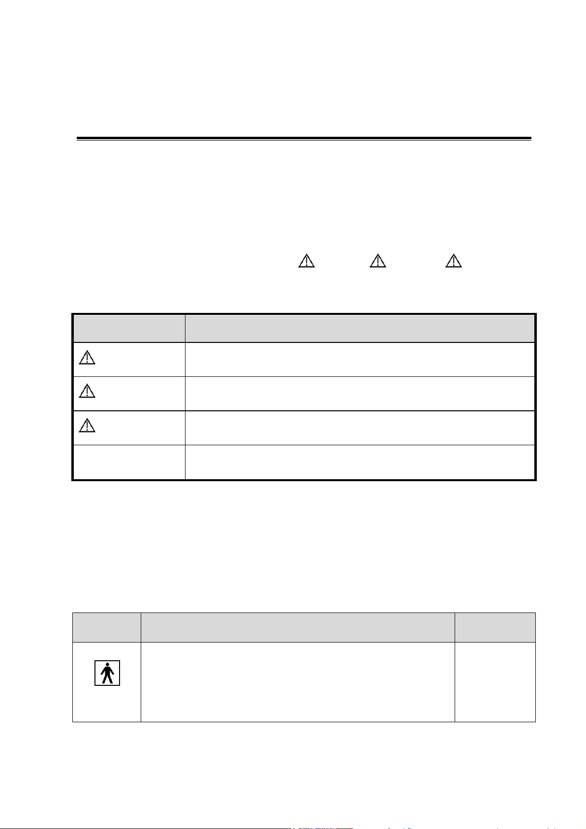
Signal word
Meaning
DANGER
Indicates death or serious injury may occur imminently in this
hazardous situation if not avoided.
WARNING
Indicates death or serious injury may occur potentially in this
hazardous situation if not avoided.
CAUTION
Indicates minor or moderate injury may occur potentially in this
hazardous situation if not avoided.
NOTE
Indicates property damage may occur potentially in this hazardous
situation if not avoided.
Symbol
Meaning
Location
Type-BF applied part
The ultrasound probes connected to this system are type-BF
applied parts.
The ECG module connected to this system is Type-BF applied
part.
Above the IO
panel
This chapter describes important issues related to safety precautions, as well as the labels and
icons on the ultrasound machine.
1.1 Meaning of Signal Words
In this operator’s manual, the signal words DANGER, WARNING, CAUTION and
NOTE are used regarding safety and other important instructions. The signal words and their
meanings are defined as follows. Please understand their meanings clearly before reading this
manual.
1.2 Meaning of Symbols
The meaning and location of the safety symbols and warning labels on the ultrasound machine are
described in the following tables, please read them carefully before using the system.
1.2.1 Meaning of Safety Symbols
Preface 1-1
Page 10
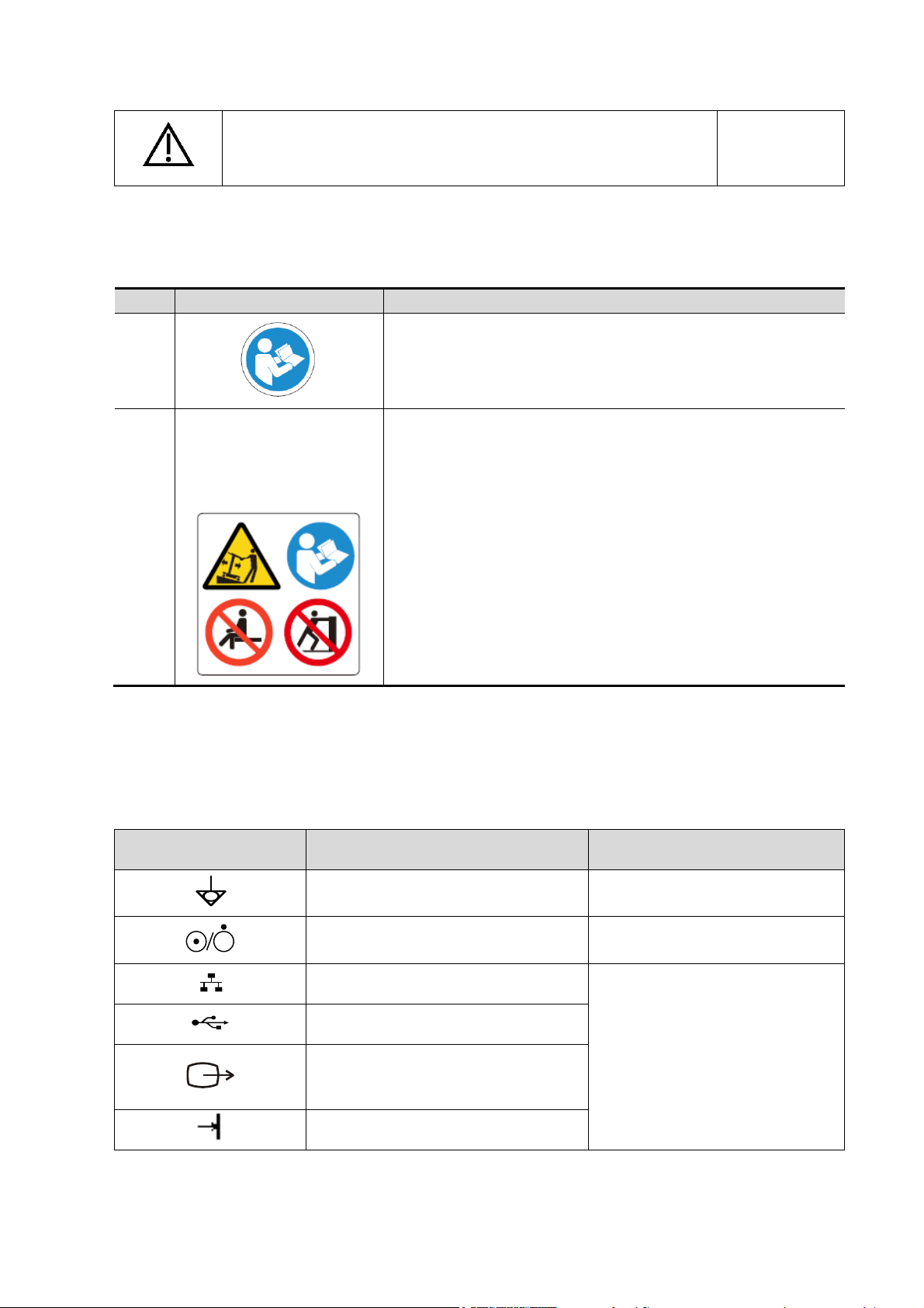
Caution
On the rear
panel
No.
Warning Labels
Meaning
1.
Please carefully read this manual before use device.
2.
The following labels are
available when the system
works with the mobile
trolley.
a. Do not place the device on a sloped surface. Otherwise the
device may slide, resulting in personal injury or the device
malfunction. Two persons are required to move the device
over a sloped surface.
b. Do not sit on the device.
c. DO NOT push the device. When the casters are locked.
Symbol
Meaning
Location
Equipotentiality
Power panel
Power button
Upper right corner on the control
panel
Network port
IO panel
USB port
Video output
Remote port
1.2.2 Warning Labels
1.2.3 General Symbols
This system uses the symbols listed in the following table, and their meanings are explained as
well.
1-2 Preface
Page 11
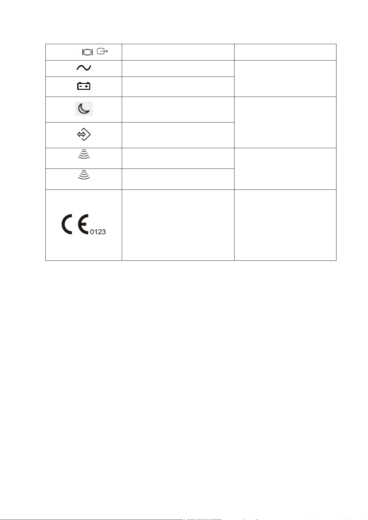
VGA port
VGA signal output
AC indicator
Lower left corner on the control
panel
Battery indicator
Standby indicator
Lower right corner on the control
panel
Hard disk indicator
A
Probe connector A
Rear panel
B
Probe connector B
This product is provided with a CE
marking in accordance with the
regulations stated in Council
Directive 93 / 42 / EEC concerning
Medical Devices. The number
adjacent to the CE marking (0123) is
the number of the EU-notified body
certified for meeting the
requirements of the Directive.
Preface 1-3
Page 12
1.3 Safety Precautions
DANGER
Do not operate this system in an atmosphere containing flammable or
explosive gases such as anesthetic gases, oxygen, and hydrogen or
explosive fluid such as ethanol because an explosion may occur.
WARNING:
1.
Do connect the power plug of this system and power plugs of
the peripherals to wall receptacles that meet the ratings
indicated on the rating nameplate. Using a multifunctional
receptacle may affect the system grounding performance, and
cause the leakage current to exceed safety requirements.
2.
Do not use any cables other than the cables provided with the
device by Mindray.
3.
Use the cable provided with this system to connect the printer.
Other cables may result in electric shock.
4.
Disconnect the AC power before you clean or uninstall the
ultrasound machine, otherwise, electric shock may result.
5.
Do not use this system simultaneously with equipment such as
an electrosurgical unit, high-frequency therapy equipment, or a
defibrillator, etc.; otherwise electric shock may result.
6.
This system is not water-proof. If any water is sprayed on or
into the system, electric shock may result.
CAUTION:
1.
DO NOT connect or disconnect the system’s power cord or its
accessories (e.g., a printer or a recorder) without turning OFF
the power first. This may damage the system and its
accessories or cause electric shock.
2.
Avoid electromagnetic radiation when perform performance
test on the ultrasound system.
3.
In an electrostatic sensitive environment, don’t touch the
device directly. Please wear electrostatic protecting gloves if
necessary.
4.
You should use the ECG leads provided with the ECG module.
Otherwise it may result in electric shock.
Please read the following precautions carefully to ensure the safety of the patient and the
operator when using the probes.
1.3.1 Electric safety
1-4 Preface
Page 13
1.3.2 Mechanical Safety
WARNING:
1.
When moving the system, you should first power off the
system, fold the LCD display, disconnect the system from
other devices (including probes) and disconnect the system
from the power supply.
2.
Do not subject the probes to knocks or drops. Use of a
defective probe may cause electric shock to the patient.
CAUTION:
1.
Do not expose the system to excessive vibration (during the
transportation) to avoid device dropping, collision, or
mechanical damage.
2.
When you place the system on the mobile trolley and move
them together, you must secure all objects on the mobile trolley
to prevent them from falling. Otherwise you should separate the
system from the mobile trolley and move them individually.
When you have to move the system with the mobile trolley
upward or downward the stairs, you must separate them first
and then move them individually.
3.
Do not move the ultrasound system if the HDD indicator is
green, sudden shake may cause the HDD in damage.
NOTE:
1.
The user is not allowed to open the covers and panel of the system, neither
device disassemble is allowed.
2.
To ensure the system performance and safety, only Mindray engineers or
engineers authorized by Mindray can perform maintenance.
3.
Only technical professionals from Mindray or engineers authorized by Mindray
after training can perform maintenance.
NOTE:
For detailed operation and other information about the ultrasound system, please refer
to the operator’s manual.
1.3.3 Personnel Safety
1.3.4 Other
Preface 1-5
Page 14

Page 15
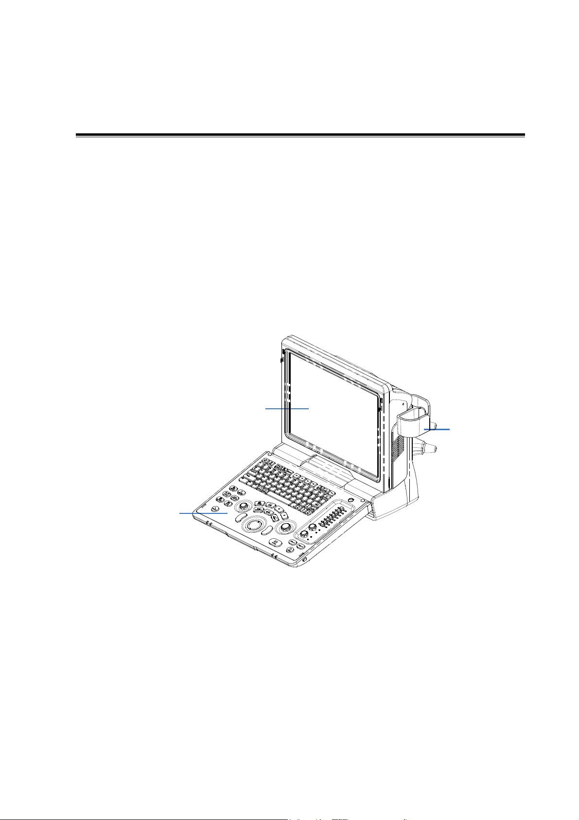
2 Product Specifications
1 2 3
2.1 Overview
2.1.1 Intended Use
Z6 series and Z8 series are diagnostic ultrasound system, which are intended for use in clinical
ultrasonic diagnosis.
2.1.2 Introduction of Each Unit
Rear view:
Product Specifications 2-1
Page 16
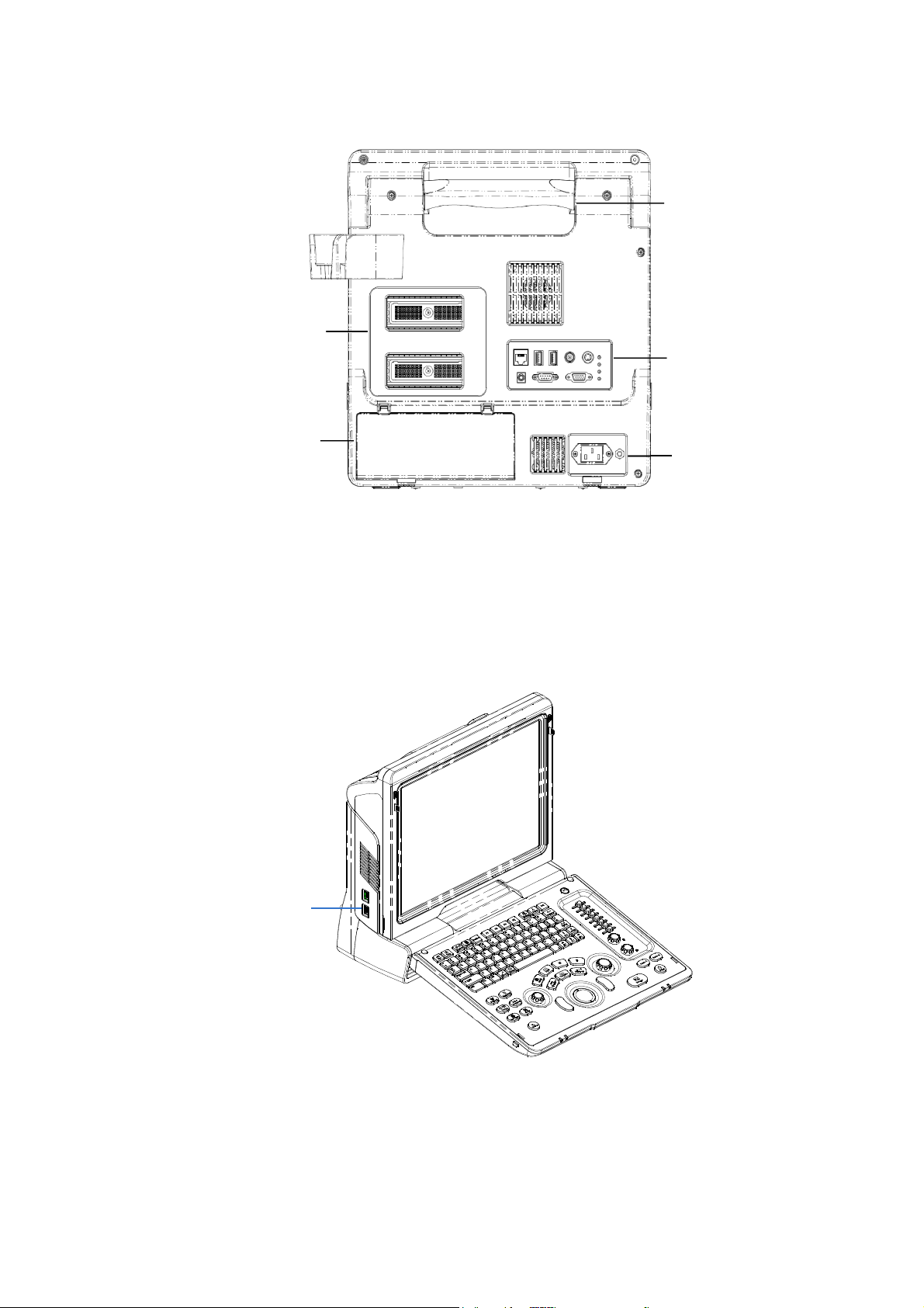
9
4
7 5 6
8
Left side:
2-2 Product Specifications
Page 17
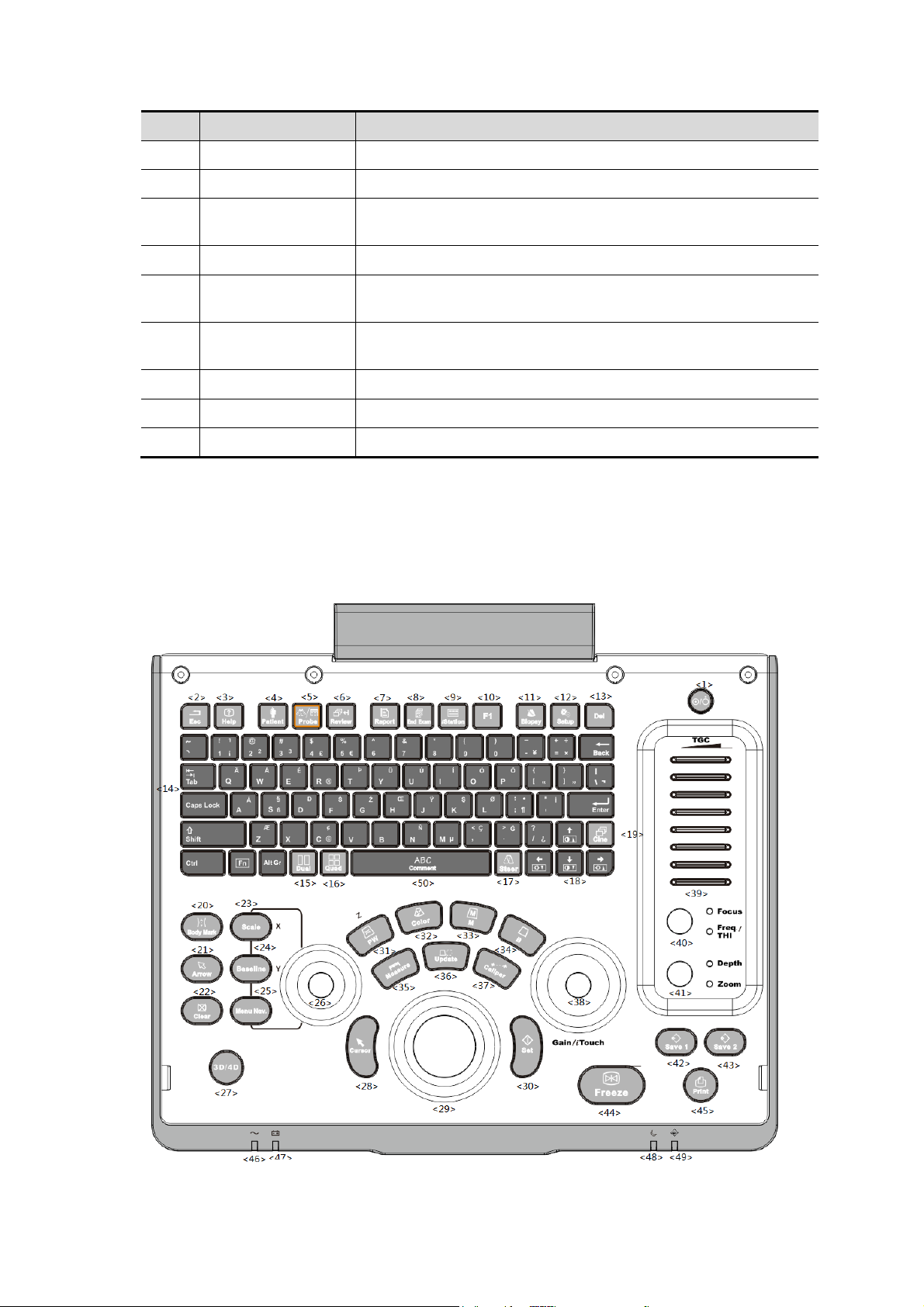
No.
Name
Function
1
Probe holder
Sets the probe
2
Display
Displays the image and parameters
3
Control Panel
Man-machine interface for operation control, for details,
please refer to “2.1.2.1 Control Panel”.
4
Handle
For lifting the machine
5
IO Panel
Signal input / output panel, for details, please refer to “2.1.2.2
IO Panel”.
6
Power supply
panel
Signal input / output panel, for details, please refer to “2.1.2.3
Power Supply Panel”.
7
Probe sockets
Sockets connecting probes and the main unit
8
Battery cover
Covering battery
9
USB ports
For connecting USB device (2 ports)
2.1.2.1 Control Panel
Product Specifications 2-3
Page 18

No.
Name
Description
Function
1
/
Power button
Off: when system is turned off;
Green: when system is turned on by pressing this
button.
2
Esc
Exit
Press to exit the current status to the previous
status.
3
Help
/
Press to display or hide the help information on
screen.
4
Patient
Patient
Information
Press to open/ exit patient information screen.
5
Probe
Probe switch
Press to switch Probe and Exam Type
6
Review
/
Press to review the stored images.
7
Report
/
Press to open or close the diagnosis reports.
8
End Exam
/
Press to end an exam.
9
iStation
/
Press to enter or exit the patient information
management system.
10
F1
User-defined key
You can assign a function to the key.
11
Biopsy
/
Press to show or hide the biopsy guide line.
12
Setup
/
Press to open/close the setup menu.
13
Del / Press to delete the comment, etc.
14
/
Alphanumeric
keys
Same as on PC
15
Dual
Dual-split screen
Press to enter Dual mode from non-Dual mode;
Press to switch between windows in Dual mode.
16
Quad
Quad-split screen
Press to enter Quad mode from non-quad mode;
Press to switch between windows in Quad mode.
17
Steer
/
Press to activate the steer function for linear probe.
18
/
Direction key
To adjust LCD brightness or contrast when pressing
with <Fn> key.
19
Cine
/
Press to enter or exit the cine review status.
20
Body Mark
/
Press to enter or exit the Body Mark status.
21
Arrow
/
Press to enter or exit the arrow comment status.
22
Clear
/
Press to clear the comments or measurement
calipers on the screen.
23
Scale
/
Press to adjust image parameter of Scale.
24
Baseline
/
Press to adjust image parameter of Baseline.
25
Menu Nav.
/
Multifunction knob
26
/
/
To adjust the image parameter combed with the key
of Scale/Baseline/Nav.Rot
2-4 Product Specifications
Page 19

No.
Name
Description
Function
27
3D/4D
/
Press to enter or exit the 3D/4D status.
28
Cursor
/
Press to show the cursor.
29
/
Trackball
Roll the trackball to change the cursor position.
30
Set
/
Press to confirm an operation, same as the
left-button of a mouse.
31
PW / Press to enter PW mode
32
Color
/
Press to enter Color mode
33
M / Press to enter M mode
34
B / Press to enter B mode
35
Measure
/
Press to enter/ exit Application Measurement
36
Update
/
Measurement status: press to switch between the
fixed and active end of the caliper;
Multi-imaging mode: press to change the currently
active window.
iScape: press to start/stop image acquisition.
37
Caliper
/
Press to enter/ exit General Measurement
38
Gain/ iTouch
/
Rotate: to adjust the gain
Press: to enter/ exit iTouch
39
TGC
/
Move to adjust time gain compensation.
40
Focus
Freq./THI
/
Press: to switch between Focus and Freq./THI;
Rotate: to adjust corresponding parameter
41
Depth
Zoom
/
Press: to switch between Depth and Zoom;
Rotate: to adjust corresponding parameter
42
Save 1
/
Press to save, user-defined key
43
Save 2
/
Press to save, user-defined key
44
Freeze
/
Press to freeze or unfreeze the image.
45
Print
/
Press to print: user-defined key.
46
/
Indicator 1
AC indicator
AC supply: light green;
Battery supply: light off.
47
/
Indicator 2
Battery status indicator
Charging: light in orange
Full: light in green
Discharge (electricity >20%): light in green
Discharge (electricity <20%): blinking in orange
Discharge (electricity <5%): blinking in orange
rapidly
Non-charge/ discharge: light off
Product Specifications 2-5
Page 20
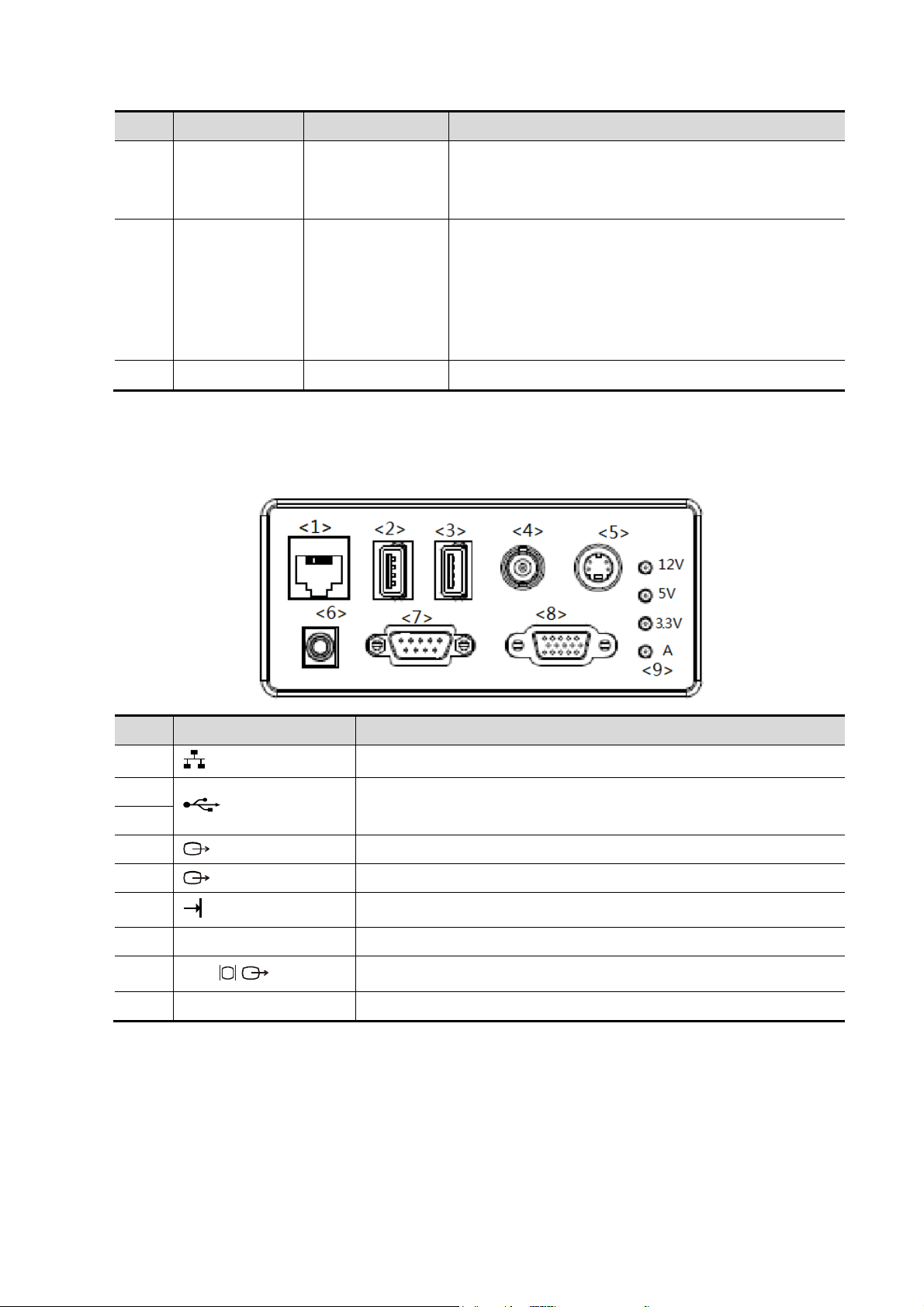
No.
Name
Description
Function
48
/
Indicator 3
Standby indicator
Standby: blinking in orange
Other status: light off
49
/
Indicator 4
HDD status indicator
Read/ write: blinking in green
Other status: light off
NOTE: DO NOT move the machine when the
indicator blinking in green. Otherwise the HDD may
be damaged by sudden shake.
50
comment
/
Press to enter or exit the comment status.
No.
Symbol
Function
1
Network port
2
USB ports
3
4
Separate video output, connecting video printer or LCD
5
Composite video output
6
Remote control port
7
ECG
ECG port
8
VGA
VGA signal output
9
/
Power indicator
2.1.2.2 IO Panel
The IO panel is on the back of the main system.
2-6 Product Specifications
Page 21
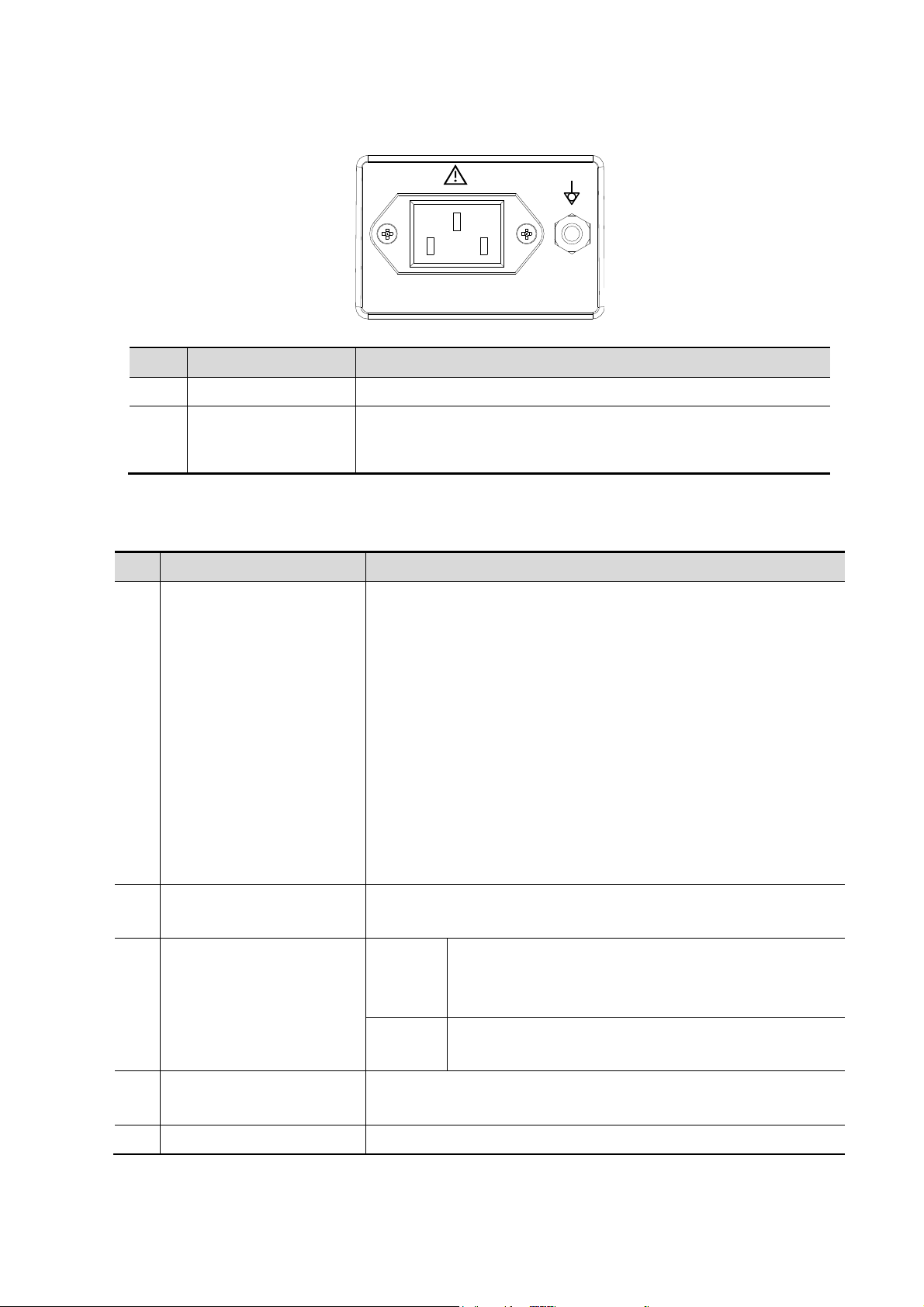
2.1.2.3 Power Supply Panel
<1>
<2>
100-240~ 50/60Hz 1.5-0.8A
No.
Name
Function
1
Power inlet
AC power inlet
1
Equipotential
terminal
Used for equipotential connection, that balances the protective
earth potentials between the system and other electrical
equipment.
No.
Item
Model
1.
Graph / text printer
HP Color LaserJet CM1015 MFP
HP LaserJet p1007
HP LaserJet 1020 plus
HP Officejet 7000 wide format
HP Deskjet 1050
HP Deskjet Ink Advantage 2020hc
HP Deskjet Ink Advantage 2010 printer
HP Officejet Pro 8100
HP Deskjet 1000-J110a
EPSON Stylus PHOTO R230
EPSON Stylus PHOTO R270
HP LaserJet CP1025
2.
Color Video Printer
SONY UP-20
MITSUBISHI CP910E
3.
Black and White Video
Printer
Analog
SONY UP-897MD
SONY UP-X898MD
MITSUBISHI P93W-Z
Digital
SONY UP-D897
SONY UP-D898MD
4.
Footswitch
USB port: 971-SWNOM (2-pedal)
USB port: 971-SWNOM (3-pedal)
5.
DVD drive
SE-208GB Samsung
2.1.3 Peripherals Supported
Product Specifications 2-7
Page 22
NOTE:
If the ultrasound system cannot recognize the SONY UP-X898MD and SONY
UP-D898MD printers automatically, you may need to change the settings on the printer:
push <PUSH ENTER> to enter the main menu and select [DIGITAL]->[DRIVER], and
select [897].
2.2 Specifications
Voltage
100-240V~
Current
1.5-0.8A
Frequency
50/60Hz±3Hz
Operating conditions
Storage and transportation
conditions
Ambient temperature
0℃~40℃
-20℃~55℃
Relative humidity
30%~85% (no condensation)
30%~95% (no condensation)
Atmospheric pressure
700hPa~1060hPa
700hPa~1060hPa
Warning :
Do not use this system in the conditions other than those
specified
Voltage
12V
Dimension
15 inch
Resolution
1024×768
Adjustable angle
≤30 degree
2.2.1 Dimensions and Weight
Dimensions:
Fold:378mm(H)×190mm(D)×415mm(W)
Unfold:396mm(H)×476mm(D)×415mm(W)
Net weight:≤8.8Kg(including battery,no probe holder)
2.2.2 Electrical Specifications
2.2.3 Environmental Conditions
2.2.4 Monitor Specification
2-8 Product Specifications
Page 23
3 System Installation
NOTE:
Do not install the machine in the following locations:
Locations near heat generators;
Locations of high humidity;
Locations with flammable gases.
WARNING:
DO NOT connect this system to outlets with the same circuit
breakers and fuses that control the current of devices such as
life-support systems. If this system malfunctions and generates
an over current, or when there is an instantaneous current at
power ON, the circuit breakers and fuses of the building’s
supply circuit may be tripped.
3.1 Preparations for Installation
3.1.1 Electrical Requirements
3.1.1.1 Requirement of Regulated Power Supply
Requirement of power supply is referring to 2.2.2.Due to the difference of the power supply
stability of different districts, please advise the user to adopt a regulator of good quality and
performance such as an on-line UPS.
3.1.1.2 Grounding Requirements
The power cord of the system is a three-wire cable, the protective grounding terminal of which
is connected with the grounding phase of the power supply. Please ensure that the grounding
protection of the power supply works normally.
3.1.1.3 EMI Limitation
Ultrasound machines are susceptible to Electromagnetic Interference (EMI) from radio
frequencies, magnetic fields, and transient in the air wiring. They also generate EMI.
Possible EMI sources should be identified before the unit is installed. Electrical and electronic
equipment may produce EMI unintentionally as the result of defect.
These sources include: medical lasers, scanners, monitors, cauterizing guns and so on. Besides,
other devices that may result in high frequency electromagnetic interference such as mobile phone,
radio transceiver and wireless remote control toys are not allowed to be presented or used in the
room. Turn off those devices to make sure the ultrasound system can work in a normal way.
System Installation 3-1
Page 24

3.1.2 Installation Condition
3.1.2.1 Space Requirements
Place the system with the necessary accessories at a proper position for convenient use.
1. Place the system in a room with good ventilation or having an air conditioning unit.
2. Leave at least 20cm clearance around the system to ensure effective cooling.
3. A combination lighting system in the room (dim/bright) is recommended.
4. Except the receptacle dedicated for the ultrasound system, at least 3-4 spare receptacles
on the wall are available for the other medical devices and peripheral devices.
5. Power outlet and place for any external peripheral are within 2 m of each other with
peripheral within 1 m of the unit to connect cables.
3.1.2.2 Network Environment
The wired LAN is supported by this ultrasound system.
Confirm the network devices and network conditions before the installation.
1. General information: default gateway IP address, and the other routers related information.
2. DICOM application information: DICOM server name, DICOM port, channels, and IP
address.
3.1.2.3 Confirmation before Installation
Please confirm the following items before installation:
1. The video format used in the region or country where the system is installed.
2. The language used in the region or country where the system is installed.
3. The power voltage and frequency used in the region or country where the system is
installed.
4. Obstetric formulae and other measurement formulae used in the region or country where
the system is installed.
5. Other settings to be used in the region or country where the system is installed but different
from the factory settings.
6. The doctor’s habits when using the system.
Please confirm the items above prior to the installation training, and do the system settings
according to the universal setting of installed region or country.
3.2 Unpacking
Tools Required: None.
Installation duration: 1 person, 0.5 hour.
3-2 System Installation
Page 25
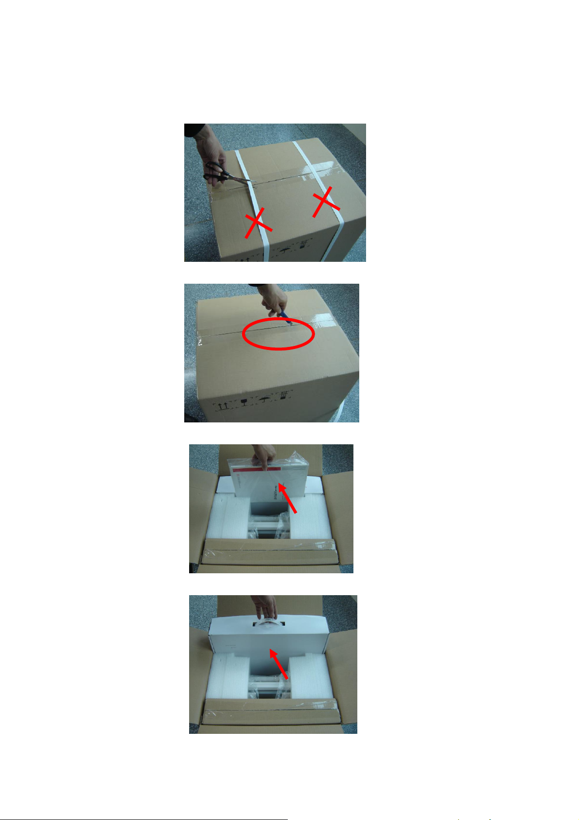
3.2.1 Unpacking
1. Use the scissor to clip the 2 rubber belts as follows:
2. Use a knife to open the tapes:
3. Take out the operation manual:
4. Take out the probe box 1:
System Installation 3-3
Page 26
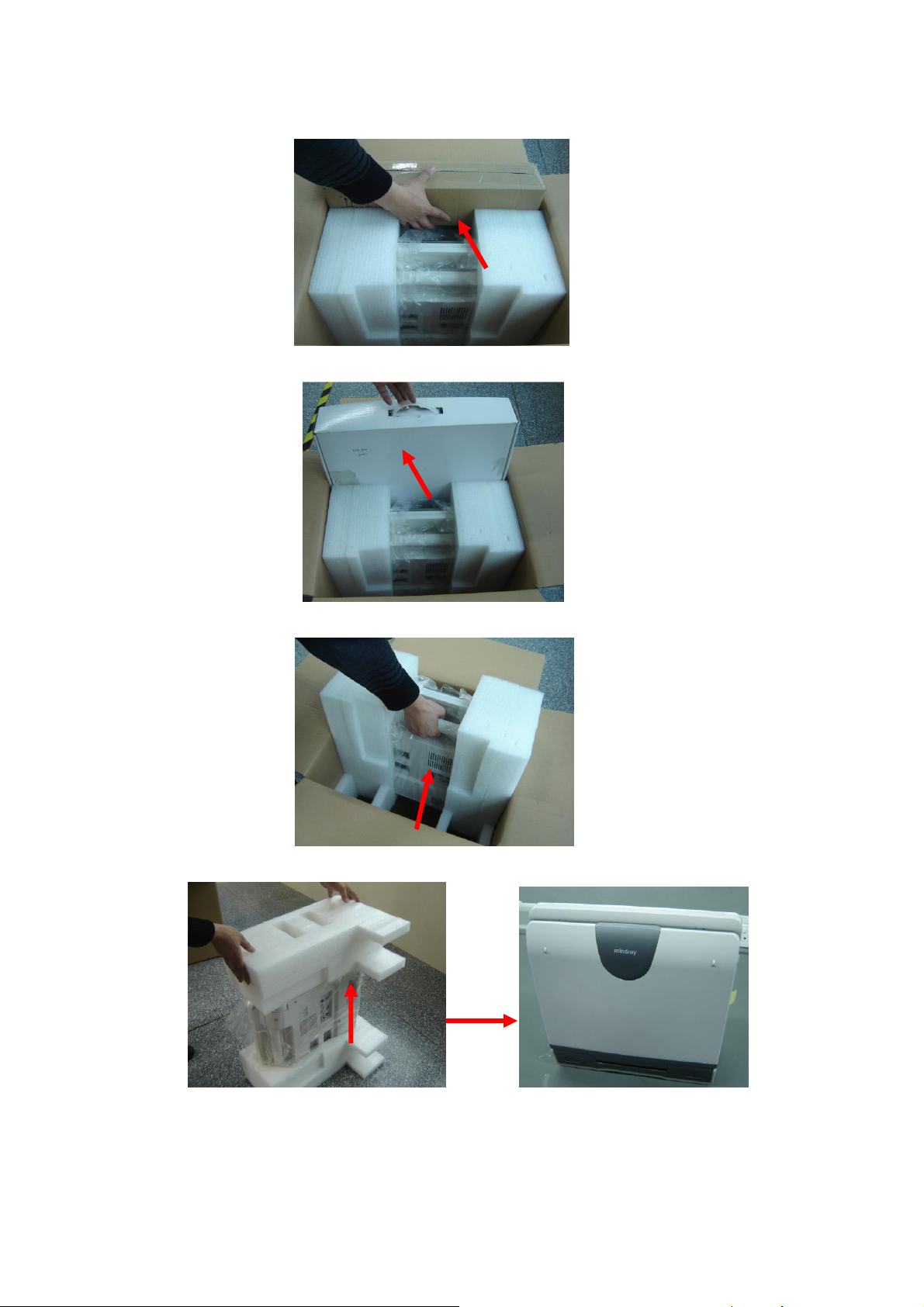
5. Take out the accessory box:
6. Take out the probe box2, as follows (the box is below the accessory box):
7. Hold the handle tightly and pull the machine with the surrounding foam:
8. Remove the surrounding protective foam to take out the main system.
3-4 System Installation
Page 27
3.2.2 Checking
Battery
1. After unpacking, check the objects in the container with the package list to see if anything is in
short supply or is wrong.
2. Inspect and make sure there is no damage to the machine, no indentation, no cracks.
3.3 Installation of Main Unit
3.3.1 Installing Battery
As shown in the following figure.
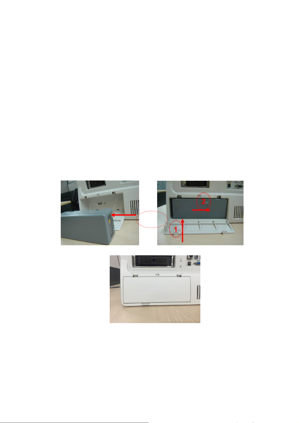
1. Open the battery cover and put the battery near the bay (Note that the battery shall be put
in correct direction).
2. Push the battery into the battery bay ①, and push to the right side as ② until it’s tightly
locked.
3. Close the battery cover.
Figure 3-1 Installing Battery
3.3.2 Control Panel Adjusting
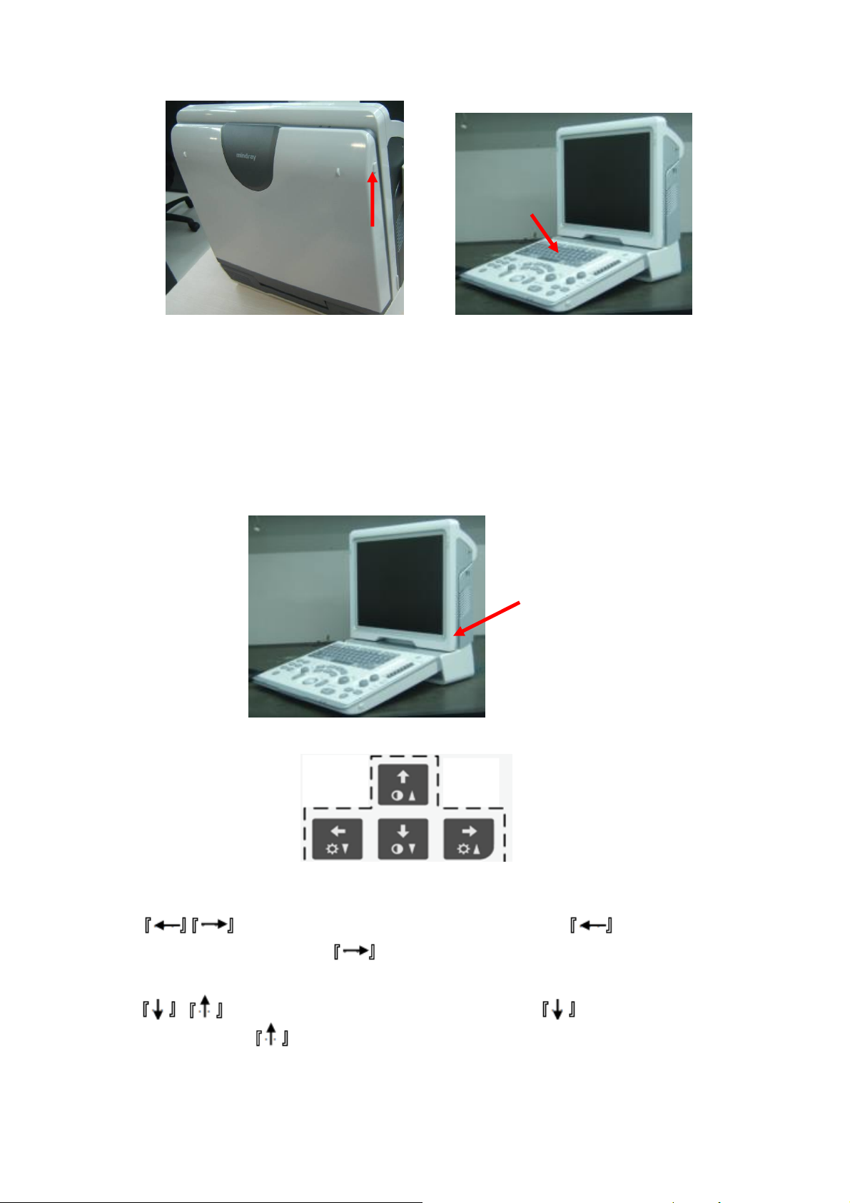
Press the ① lock buttons on the both sides of the control panel as illustrated in the following
picture, open the control panel.
System Installation 3-5
Page 28
Hold the bottom of the
monitor to adjust the
display angle
The clip on the right
side keyboard
Maximum
folding
position
Figure 3-2 Control Panel Adjustment
3.3.3 Display Adjusting
1. Open the display as described in 3.3.2
2. Put the finger into the bottom of the display and pull the display to tilt the display (30
degrees max.)
3. Ear off the screen protective film.
Figure 3-3 Open and tilt the display
Press <Fn>+ directional keys to adjust brightness and contrast.
Brightness Adjustment:
brightness; and press <Fn>+ to increase the brightness.
Contrast adjustment:
and press <Fn>+ to increase the contrast.
3-6 System Installation
refer to the brightness control keys; press <Fn>+ to decrease the
, refer to the contrast control keys; press <Fn>+ to decrease the contrast;
Page 29
Restore the factory default settings
NOTE:
On the monitor, the brightness adjustment comes before contrast. After readjusting the
monitor’s contrast and brightness, adjust all preset and peripheral settings.
Press the
holder
downwards to
lock it
Open the page via “Setup <F10>→General” and restore the brightness/contrast to factory
default setting.
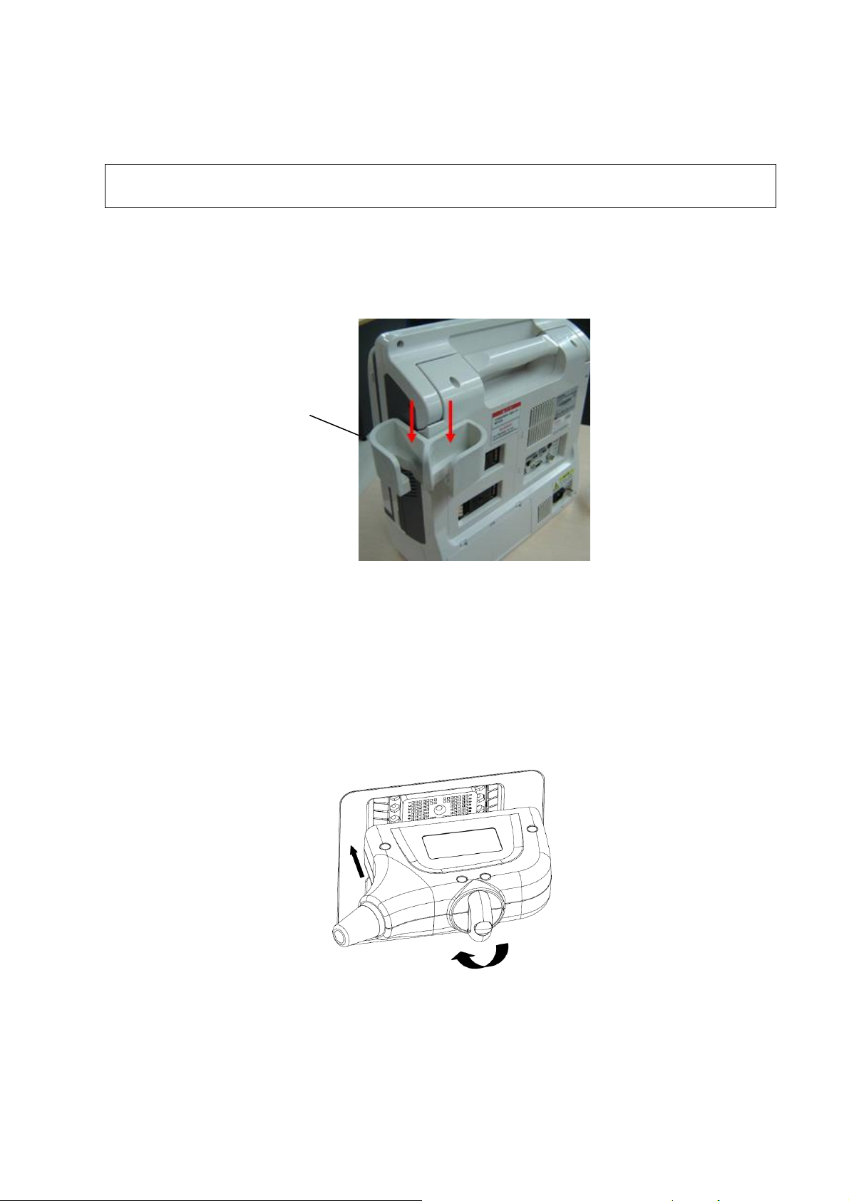
3.3.4 Installing Probe Holder
Fix the probe holder hanger into the groove in the right side and the rear-right side of the main
unit, and push downwards to confirm the installation.
Figure 3-4 Installing the Probe Holder
3.3.5 Connecting a Probe
1. Check the probe connector, if is not open, Turn the locking lever anticlockwise to open it.
2. Keep the cable toward probe holder and insert the connector into the port.
3. Turn the locking lever 90° clockwise in the horizontal position to lock the probe connector.
4. Place the probe properly to avoid being trod or wrapping with other devices. DO NOT allow the
probe head to be hung freely.
5. To disconnect the probe, turn the locking lever 90° anticlockwise and pull the probe straight out.
System Installation 3-7
Page 30
NOTE:
Before inserting the connector into the probe port, inspect the connector pin. If the pin is
bent, do not use the probe until it has been inspected / repaired / replaced.
USB port
Cable of the
footswitch
3.4 Installing Peripherals
For the models of the supported peripherals, please refer to “2.1.3 Supported Peripherals”.
3.4.1.1 Footswitch Installation
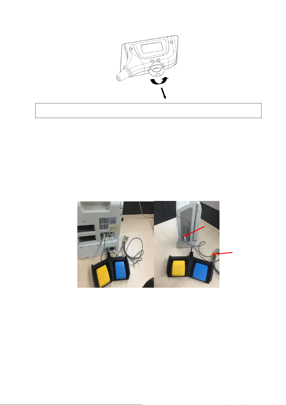
1. Connecting: Take 971-SWNOM as an example: insert the USB connector to the system
available USB ports (on the left and rear of the machine).then the footswitch can be used
directly.
2. For settings of footswitch, please refer to 3.5.3 system preset.
Figure 3-5 Footswitch connection
3.4.2 Video Printer Installation
Analog video printer:
1. Connect one end of the signal line to the Video In interface of the printer, and the other to
the video output port in the ultrasound system IO panel.
2. Connect the Remote control line to the Remote interface in the ultrasound system IO
panel.
3-8 System Installation
Page 31
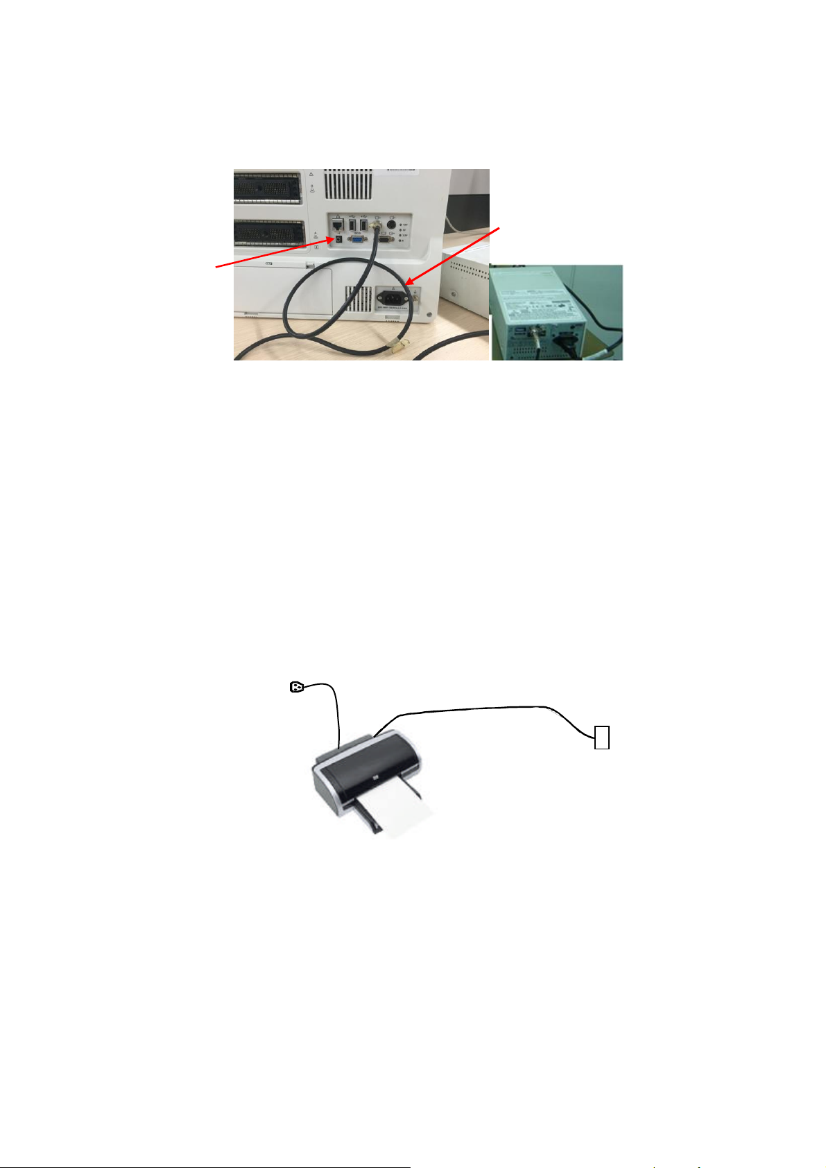
3. Insert the power cord to a power supply receptacle that is well grounded.
Remote port
Video cable
Figure 3-6 Installing Analog Video Printer
Digital Video Printer
1. Connect one terminal of the data cable of the video printer to the USB port of the
ultrasound system and the other terminal to the video input port of the video printer;
2. Insert the power cord to a power supply receptacle that is well grounded.
3. Please refer to 3.5.4 for the driver installation. And you need not install the driver of the
printer listed in section “2.1.3”.
3.4.3 Installing a Graph / Text Printer
A graph / text printer is configured with power cord and data cable, and is connected to the
system via the USB port. The connection method is described as follows:
1. Connect the data cable to the USB port in the ultrasound system.
2. Plug the power plug into a power supply receptacle that is well grounded.
3. Please refer to 3.5.4 for the driver installation. And you need not install the driver of the printer
listed in section “2.1.3”.
3.4.4 Installing External DVD-R/W
1. Connect the USB cable connector of the external DVD recorder to the USB port in the
System Installation 3-9
Page 32
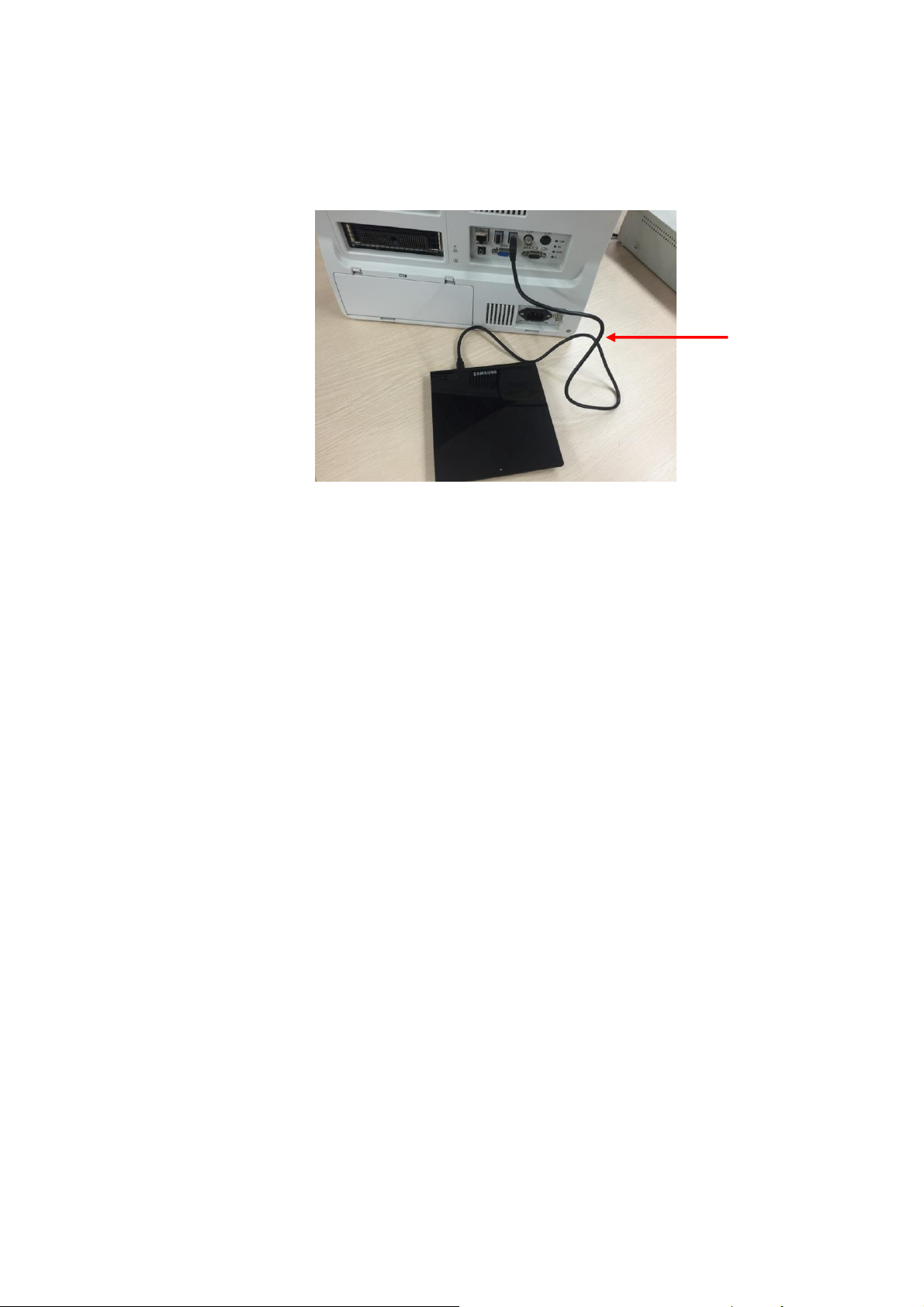
ultrasound system;
USB
cable
2. Connect the power supply adapter plug of the DVD recorder to an appropriate receptacle that
is well grounded.
Figure 3-7 Installing External DVD
3.5 System Configuration
3.5.1 Power ON / OFF
Connect the system power cord to the AC power, and make sure the ultrasound system and
other optional devices are correctly connected.
When the AC indicator is green, you can turn on the power button (located at the upper right
corner of the system) to initiate the system. After being normally rebooted, it will display image
interface. Or press the power button directly when the battery is of sufficient capacity.
3.5.2 Enter Doppler
After the system is powered on after initiation (about 30S), it enters Doppler directly:
3-10 System Installation
Page 33
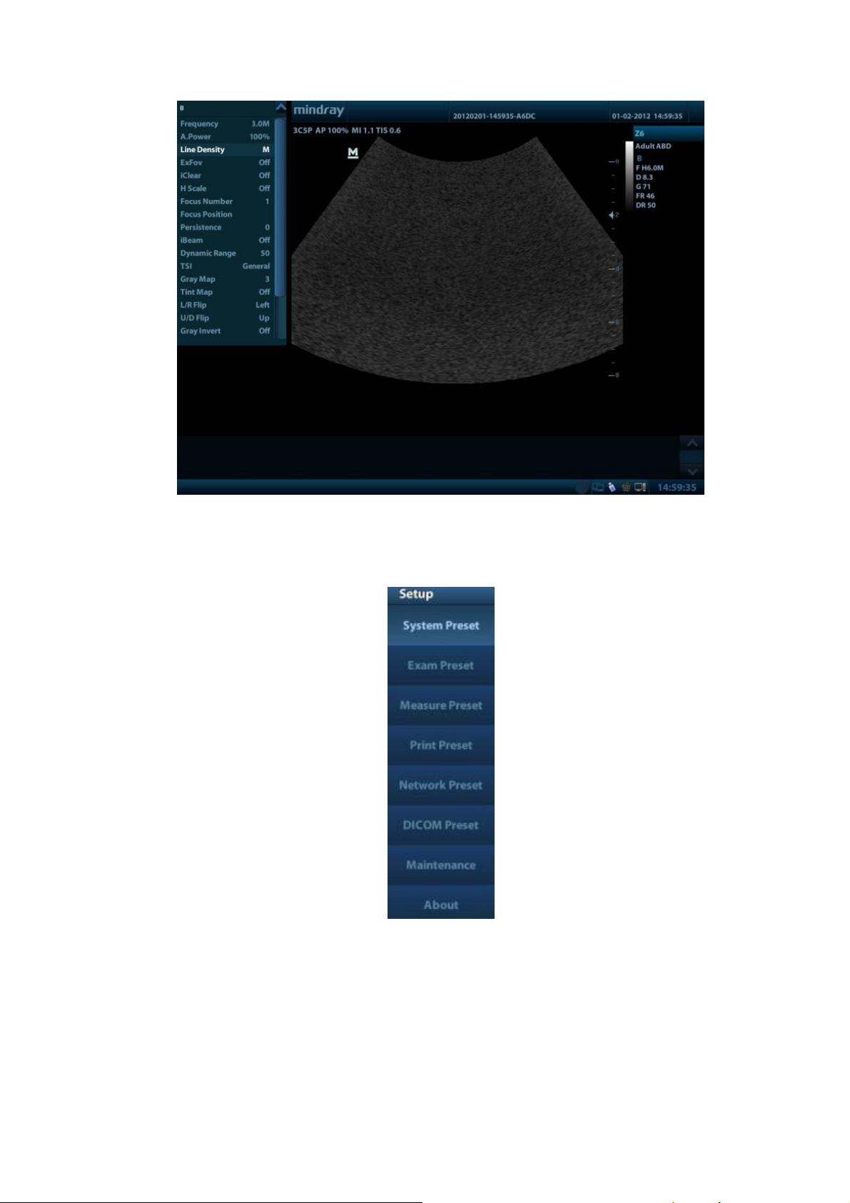
3.5.3 System Preset
1. Press the <Setup> key to enter the [Setup] menu.
2. Click <System Preset> to enter the screen as follows:
Region
System Installation 3-11
Page 34
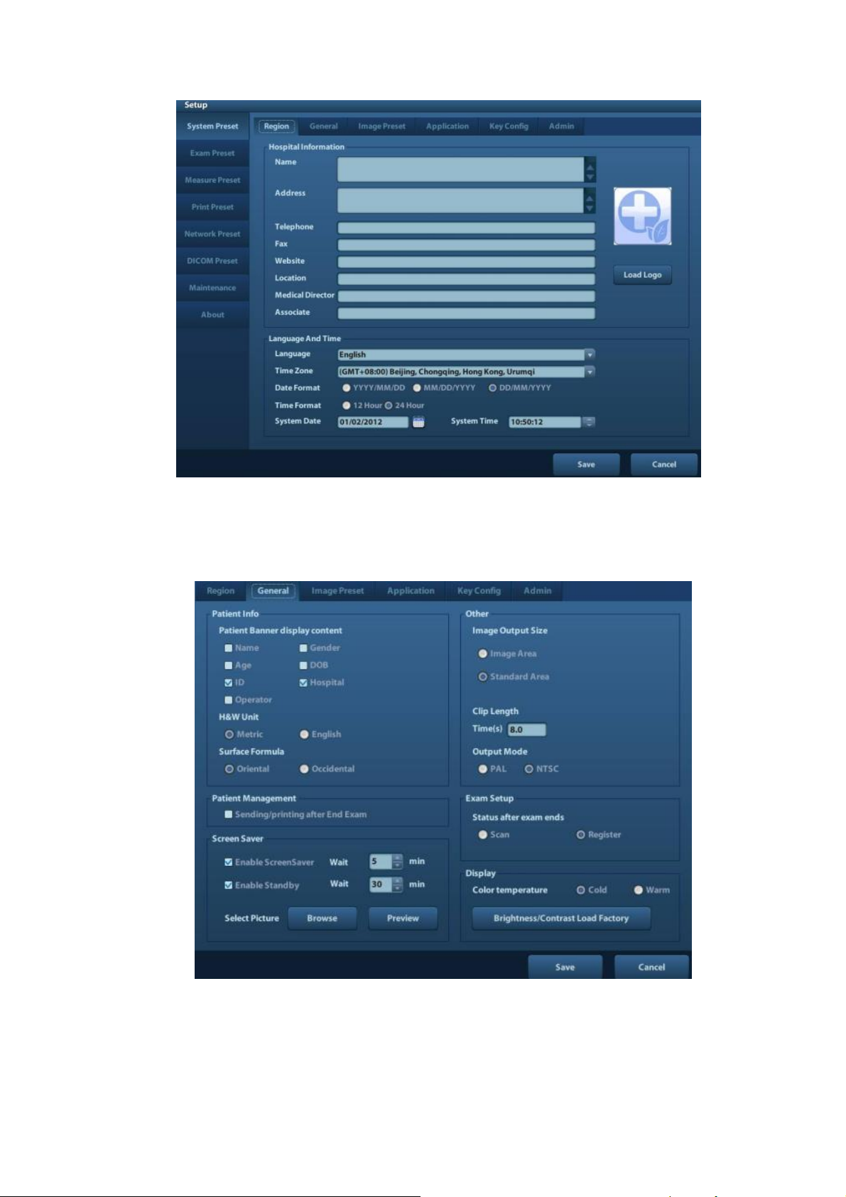
In the Region page, set the system language, date format, date, time and hospital related
information, etc.
General
Click <System Preset> to enter:
In this page, set the time of standby, brightness/contrast and color temperature of display,etc.
Key Config
3-12 System Installation
Page 35
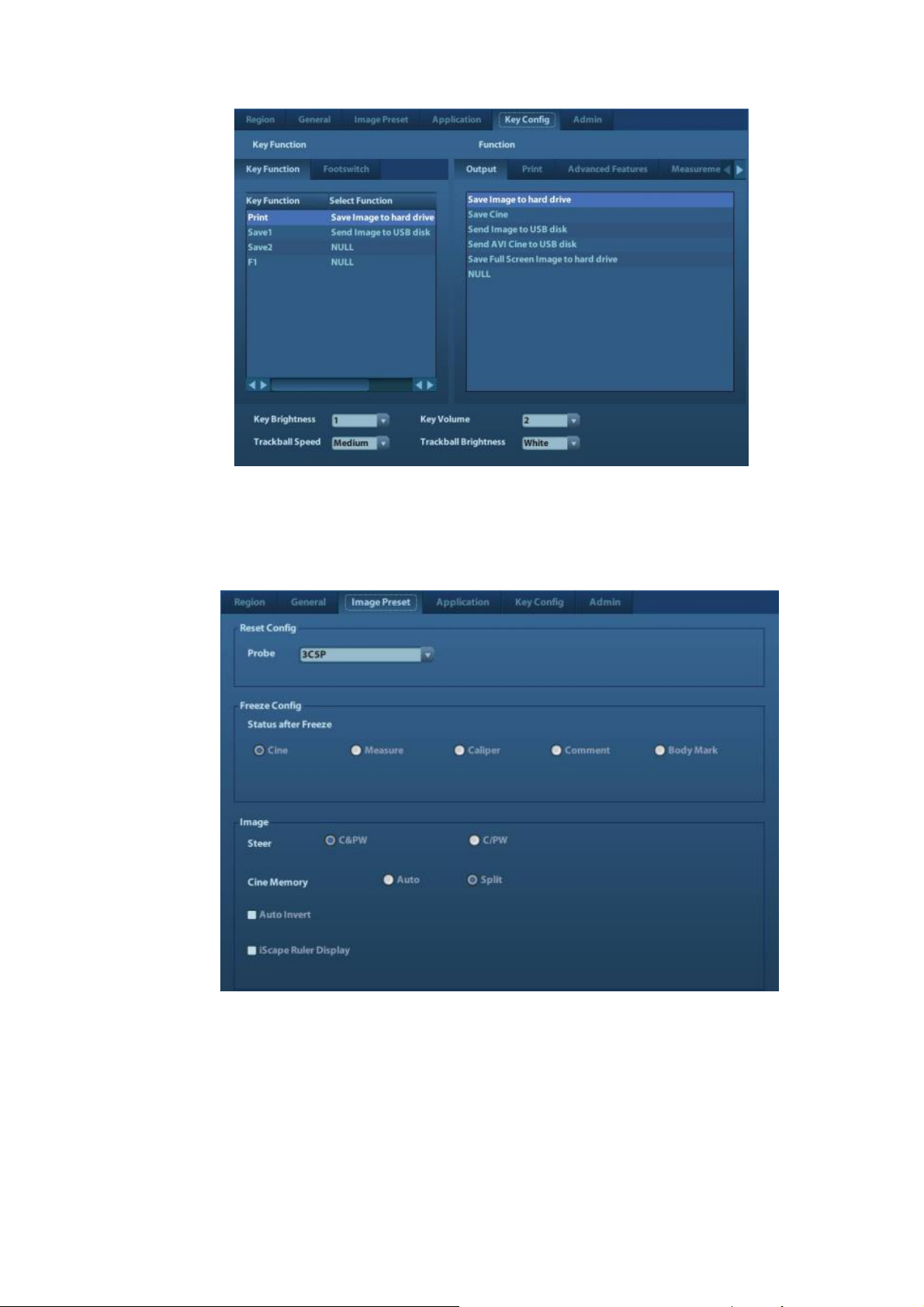
1) Function of keyboard keys F1 and the footswitch keys (left, mid, right) are user-defined.
2) Key brightness, key volume, trackball backlight and trackball sensitivity can be adjusted.
Image Preset
Click [Image Preset] to enter:
General image parameters can be set in this page.
3.5.4 Print Preset
1. Press <Setup> and click [Print Preset] to set video printer, graph/text printer parameters:
System Installation 3-13
Page 36
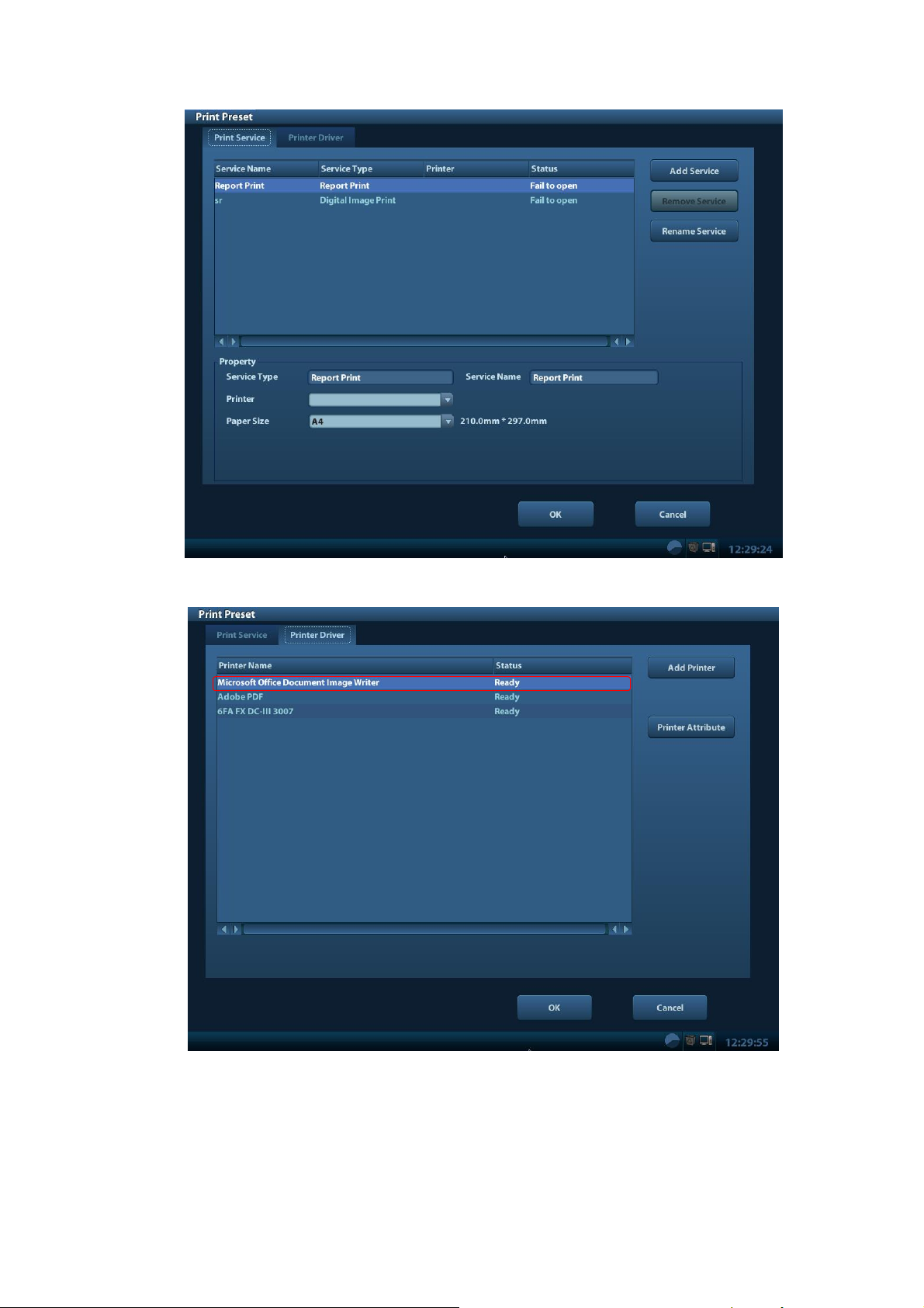
2. After connecting the local printer, Click “Printer Driver”, the system will display the printer name
and status (Ready) automatically which already installed printer driver successfully.
3. Return “Printer Service” page, Select the corresponding service from the printer list and
increase the service.
The system integrates drivers of HP printers, after HP printers are connected, drivers will be
installed automatically (about 10s).If auto installation fails, icon will display on the right lower corner
of the screen to warn you that manual installation is necessary. The driver installation method is as
follows:
3-14 System Installation
Page 37
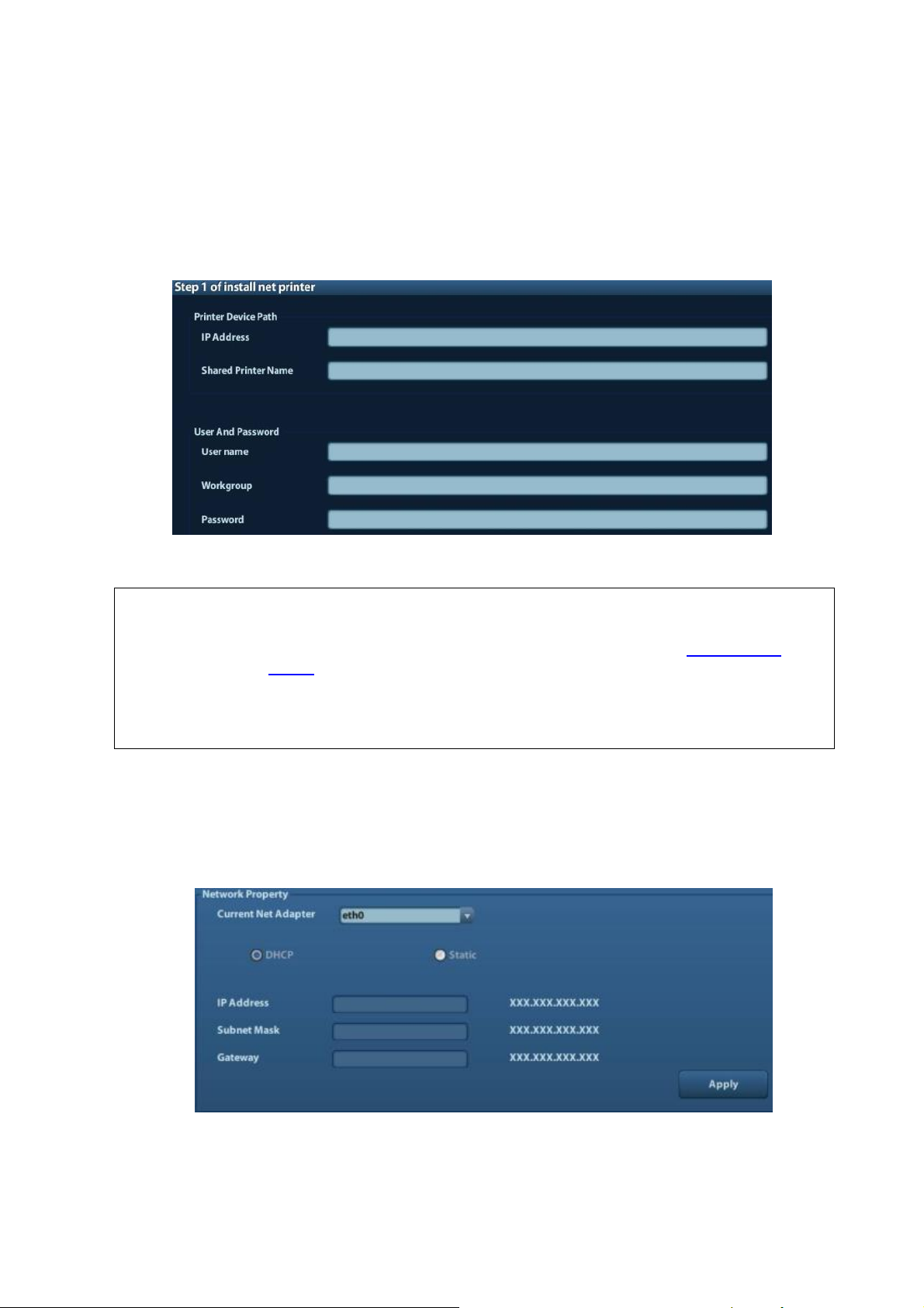
a) Download the ppd file from HP official website (contact R&D engineer if necessary), and copy
NOTE:
1.
Before connect the network printer, make sure the ultrasound system and the
printer are in the same network domain, and the network is working normally.
2.
The IP address and the server name should be valid, e.g. \\10.2.40.123 or
\\5-HP, otherwise, the system will fail to connect.
3.
If the server has set accessing limitation, the system will prompt a dialogue
box to identify the user. Enter the correct user name, domain name and
password, and then click [OK].
the ppd file to the storage device (USB disk as an example).
b) Connect the U disk to the USB port nearside the control panel of ultrasound system, click the
icon to pop up the screen, select the U disk to run the ppd file and finish the installation.
Add network printer
1. In “Printer Driver” screen, click [Add Network Printer] to pop up the screen, enter the necessary
information (IP address, shared printer name, server name, domain name and password).
2. After successful connection, the newly added network printer name will be shown in the printer
driver list.
3.5.5 Network Preset
3.5.5.1 Network Preset
Open “[Setup]→[Network Preset]” to enter the screen.
1) Please select the network type according the actually status, Select “DHCP”, click [OK].
2) Or, select “Static”, and input the IP address, subnet mask and gateway, then click [OK].
System Installation 3-15
Page 38
Name
Description
Current Network Adapter
To select the network connection mode
DHCP
/ Static
If “DHCP” is selected, IP address will be automatically obtained
from DNS server; if “Static” is selected (using static IP address),
you need to enter the IP address.
IP Address
IP address of the system should be at the same network segment
with the server IP.
Subnet Mask
Used to set different network segment.
Gateway
Used to set the gateway IP.
3.5.5.2 DICOM Preset
NOTE:
Only if DICOM basic option is configured, [DICOM Local], [DICOM Server], [DICOM
Service] are available.
NOTE:
1.
AE Title should be the same with the SCU AE Title preset in the server
(PACS/RIS/HIS).
2.
DICOM communication port in the ultrasound system should be the same
with the one in the server.
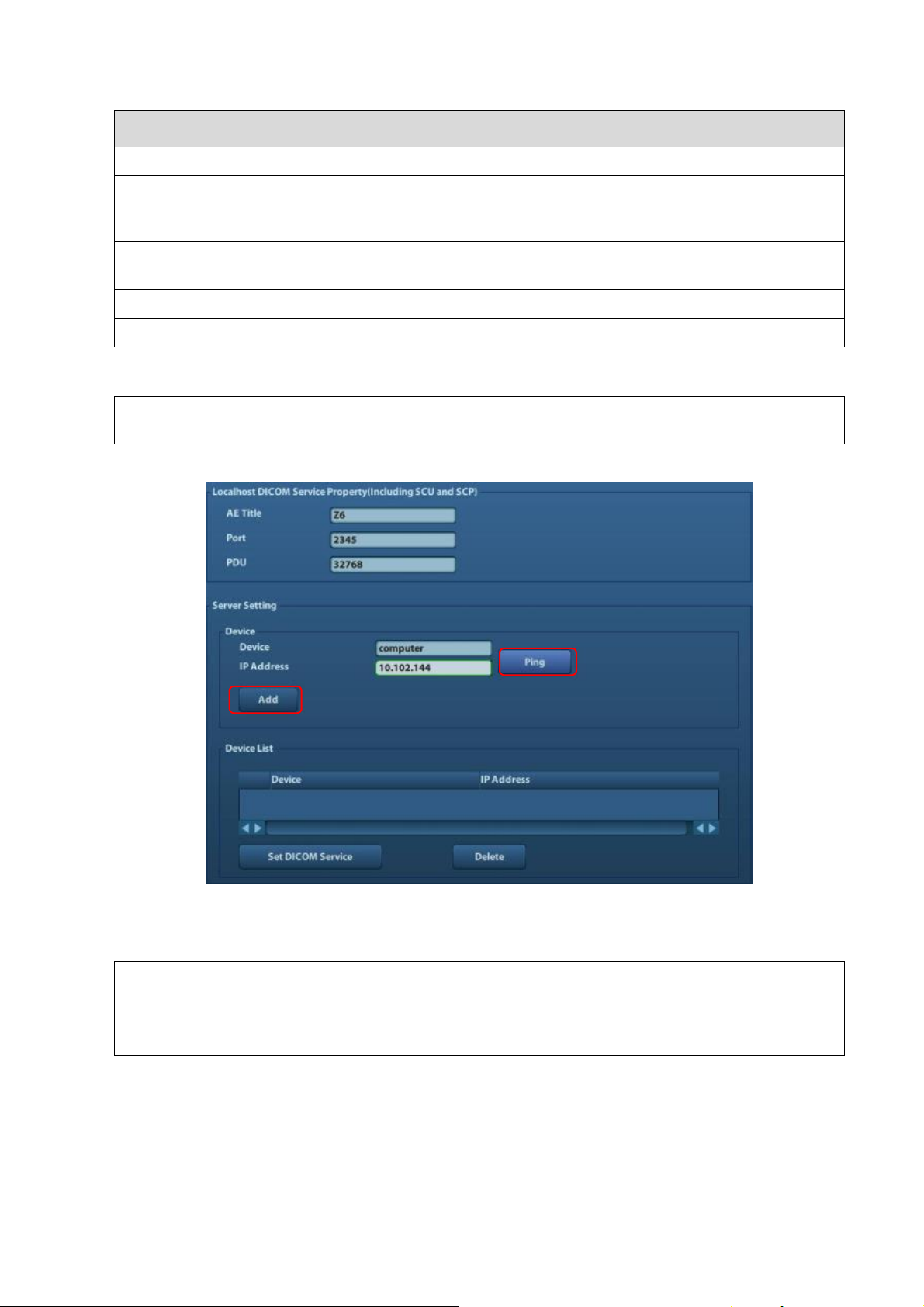
1. Click [DICOM Preset] to open the DICOM preset screen.
DICOM Setting
Enter the AE Title of the ultrasound system, port and PDU according to the actual situation, and
then click [OK] to exit the screen.
DICOM Server Setting
1) Enter the device name and the IP address.
2) You can ping other machines to verify connection after entering the correct IP address.
Also you can check the connection of the already added server in the list.
3-16 System Installation
Page 39
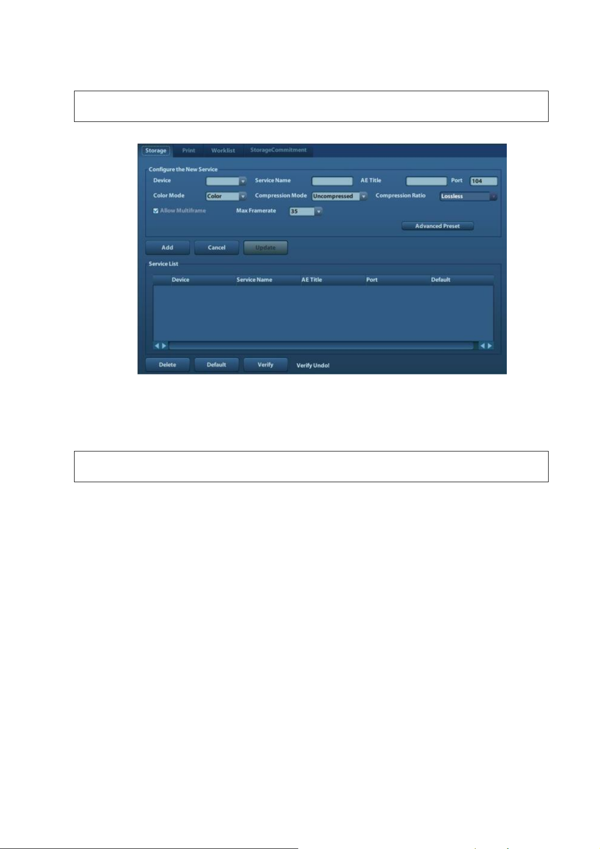
3) If connection is successful, click [Add] to add the service to the Service list.
NOTE:
If the currently entered name has already existed, the system will pop up: “The server
name exists!” Click [OK] to enter another name.
NOTE:
DICOM Work list can be configured only after DICOM Basic is configured, and if
DICOM Work list function is not configured, the “Work list” page is not accessible.
2. Click [DICOM Service] to open the DICOM Service screen.
Only when the system is configured with DICOM basic function module, and installed DICOM
Work list, MPPS, DICOM Structured Reporting and Query/ Retrieve modules, can the
corresponding preset settings be found in DICOM Service screen.
The DICOM Service Setting is used to set properties of DICOM services as Storage, Print, Work
list, MPPS, Storage Commitment and Query/ Retrieve.
System Installation 3-17
Page 40
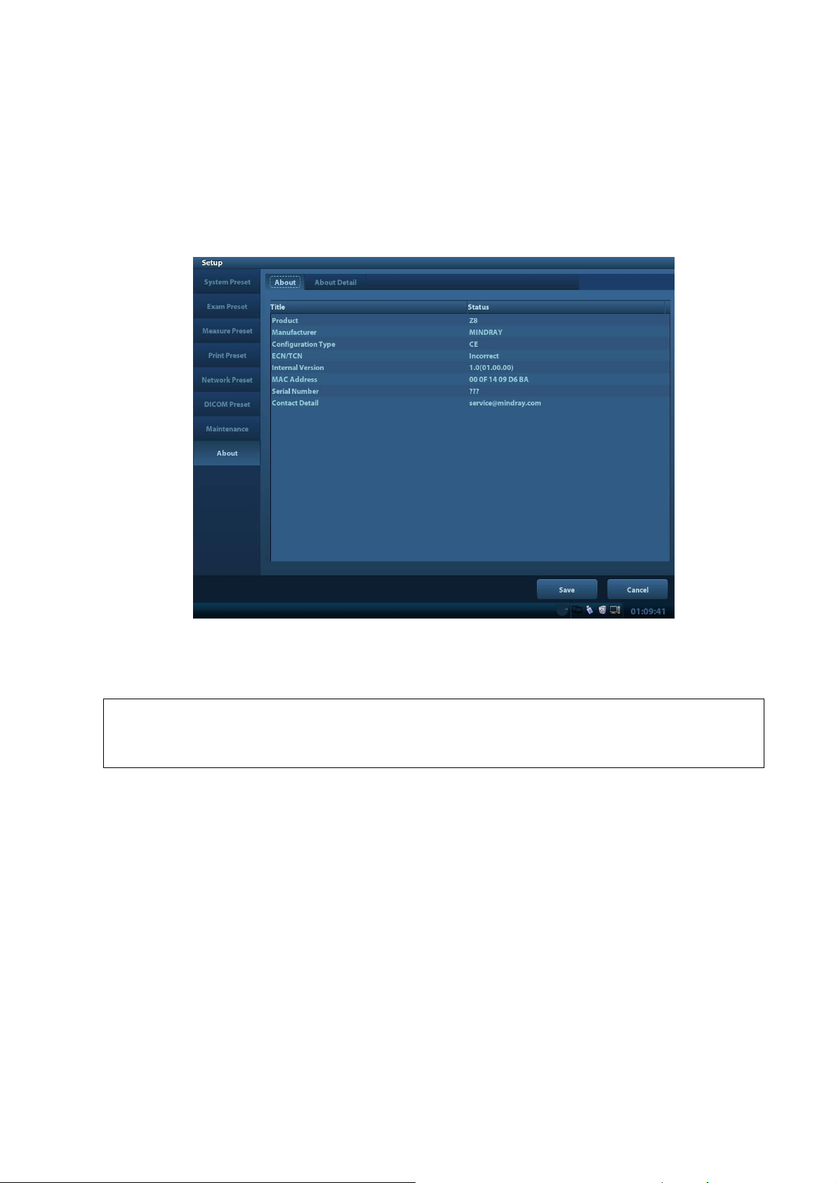
3.5.6 System Information
NOTE:
1.
Be sure to confirm the system information before and after the software
maintenance.
2.
Ask the user to save the current system information if necessary.
In System Information screen, it displays the product configuration, software version, hardware
& boards, and driver related information. You can check the product information here.
1. Press the <Setup> and click [System Info].
2. Click [About Detail] to check the detailed board information.
3. Click [Save] to export the information in the format of “*.TXT”; click [Exit] to return to the Setup
menu.
3-18 System Installation
Page 41
4 Hardware Principle
DC-DC
board
AC IN
Battery
connecting
board
Battery
AC-DC
board
Main
board
Probe
board
IO board
Fan
Charge/
discharge
Fan
Monitor
Control panel
Power supply
Comm&control
Ultrasound signal
CPU
module
4D drive
board
4.1 General Structure of Hardware System
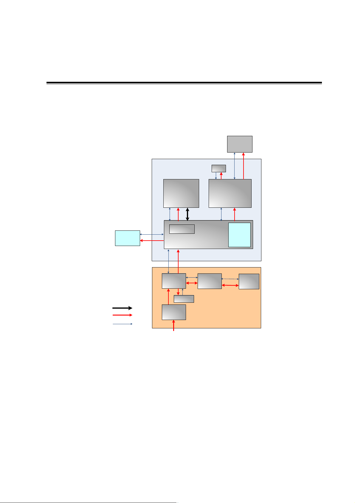
Figure 4-1 Schematic Diagram of System
As a portable black-and-white ultrasonic product,the system supports two probe slots.
The detailed structure of hardware system is in the figure above, and they can be divided into 4
modules:
Main unit module
Power supply module
Monitor module
Control panel module
The detailed description of 4 modules will be in the following:
Hardware Principle 4-1
Page 42
4.2 Main Unit
High-voltage
switch
Relay
CPLD
Probe socket
A
(156 pin)
Relay driving
circuit
Probe
socket B
(156 pin)
POUTA[128:1]
POUTB[128:1]
Aprobe socket control signal
(note 1)
RELAY_EN
PRB_A_VDD_EN,
PRB_A_VCC_EN,
HV_PWR_SW1
BOARD_ID[7:0]
3.3V/5V/+95V/-95V
Power ON/OFF
Control circuit
POUT[128:1]
Drive
LC filter
Drive
Drive
Bprobe socket control signal
(note 2)
PRB_B_VDD_EN,
PRB_B_VCC_EN,
HV_PWR_SW2
3.3V/5V/+95V/-95V
Power ON/OFF
Control panel
BOARD ID
CTRL_PROBE_A_245_OE_N
+5V
+95V
-95V
RELAY_PWR_EN
Note:
1.A probe socket control signal:
PROBE_A_SPI_CLK/CLK
PROBE_A_SPI_CS/nLE
PROBE_A_SPI_DIN/DATA0
PROBE_A_SPI_DOUT/DP_SWITCH
PROBE_A_SPI_nWP/DATA1
PROBE_A_SPI_SEL
Probe board
control signal
CTRL_PROBE_B_245_OE_N
PRB_A_ON
VDD
A probe socket control
signal
VDD
PRB_B_ON
probe socket control
signal
Drive
Highvoltage
switch
signal
Drive
Drive
LDOD+3V3
A+5V
A+95V
A-95V
+5V
D+3V3
2.B probe socket control signal:
PROBE_B_SPI_CLK/CLK
PROBE_B_SPI_CS/nLE
PROBE_B_SPI_DIN/DATA0
PROBE_B_SPI_DOUT/DP_SWITCH
PROBE_B_SPI_nWP/DATA1
PROBE_B_SPI_SEL
Z6 series probe board
Relay
Relay
4D signals
4D signal(note
3)
4D signals(note
3)
3.4D including:
4D_SIN+
4D_SIN 4D_COS+
4D_COS 4D_HALL
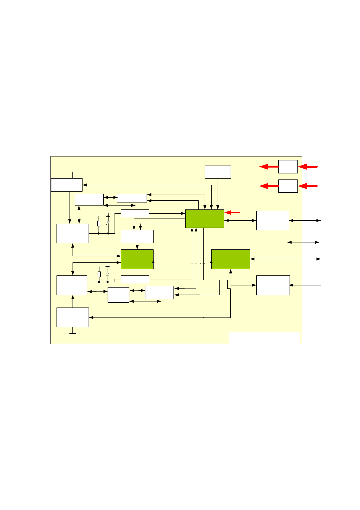
The main unit mainly involves 3 boards:
Probe board
Main board
IO board
4D drive board
4.2.1 Probe Board
4.2.1.1 Probe Board of Z6 Series and Z8 series
Figure 6-3 Principle Diagram of Z6 Series and Z8 series’ Probe Board
The function of Z6 series and Z8 series probe board describes as following:
The ultrasound signal is transferred from 64-channel to 128-array by the high-voltage
switch on the probe board.
Probe information could be obtained by probe board via reading probe online signal and
probe ID.
4-2 Hardware Principle
Page 43
The probe board supplies power to corresponding Flash of saving probe ID when reading
Main
board
HVISO
32ch/
64ch
BF FPGA
Control
signal
DATA
DSP
FPGA
High-voltage
control signal
IQ
DDR2
UPLOAD
DDR2
PCIE X1
CPLD control signal
Rx9~
16
Rx49~64
Or
Rx25~32
Rx1~8
…
...
LVDS*8
Tx9~16
Tx49~64
Or
Tx25~32
Tx1~8
Probe
board
PCIE
PHY
Comm
control
bus
Control
signal
…
...
High-
voltage
pulse
output
circuit
Drive
circuit
Tx
TGC
8-channel
digital
LNA VGA ADC
Rx
8-channel
analog
Control signal
Control signal
main CPU
Clock
circuit
Clock
clocl
4D drive
board
4D drive signal
probe ID, and Flash power shuts off after getting probe ID.
Support two 156-array probes (A and B), and only one probe could be chosen by relay
switching on the probe board.
Support 192-array probe and bi-planar probe.
Support 192-array probe and bi-planar probe; the probe board controls the probe 5V output;
the main board supplies the ±95V output to 192-array probe or bi-planar probe.
Support 4D probe; recognize the probe via the ID code; switch the 4D drive signal via the
electrical relay to make the 4D probe work normally.
4.2.2 Main board
The main board could be divided into two parts: front-end of the main board and back-end of the
main board.
4.2.2.1 Front-end of main board
Hardware Principle 4-3
Figure 4-4 Principle Diagram of Front-end of the Main Board
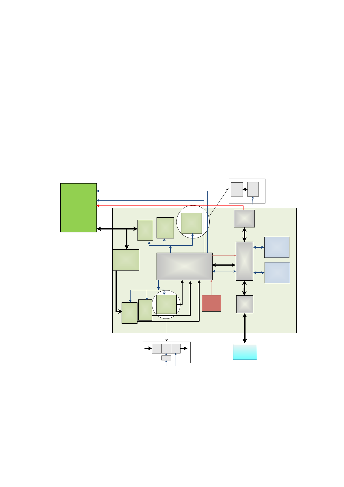
As shown in the figure above, ultrasound front-end internal structure consists of ultrasound
receiving module(Rx1~Rx64), ultrasound transmission module(Tx1~Tx64), high-voltage isolation
module(HVISO), BF FPGA module, DSP FPGA module ,PCIE_PHY module and so on.
Function describes as following:
Support 32/64-channel high-voltage isolation(HVISO)to protect ultrasound receiving
module(Rx)to avoid ultrasound transmission high-voltage contamination.
Page 44
32/64-channel transmission wave forms according to scanning time sequence and control
IO board
PCIE
PHY
PCIE X1
SATA
HDD
VGAUSB
Video
S-
Video
Remote
Ethernet
MUL FPGA
LPC
LVDS
USB
CPU module
SATA
+12V
LVDS
Display
SMBUS
Control signal
of the inverter
Video
Encoder
Cont
rol
Data
USB
lateral
USB
System monitor
circuit
Power supply
module
ARM control signal
HDD
indicator
Control signal of
parameter board
Control panel
Main board
Status
indicator
5V
12V
3.3V
POWER
12V
5V
5VSTB
Status
indicator
Power_BTN_N
Closed status indicator on
the control panel
ARM
Power
manage
ment
FPGA
Control
signal
Power on/off
signal
Audio
Codec
Audio
power
amplifier
Speaker
ECG
parameters.
32/64-channel transmission wave forms to 32/64-channel high-voltage transmission wave
by driver.
Echo receiving LNA is to enlarge fixed gain.
By the control of TGC, echo receiving carries out variable gain amplification by depth.
32/64-channel analog echo could be switched to 32/64-channel digital signal by ADC.
BF FPGA combines 64-channel echo signal to output to DSP FPGA, and DSP FPGA is
sent to signal processing to a single image which is uploaded to CPU module by
PCIE_PHY, then CPU module performs post processing.
PCI_PHY implements PCIE interface switching.
BF FPGA can communicate with the CPU module through transferring DSP FPGA.
The CPU module communicates with the probe board via BF FPGA.
DSP FPGA controls the 4D drive board to output the 4D signal to the probe board.
4.2.2.2 Back-end of Main Board
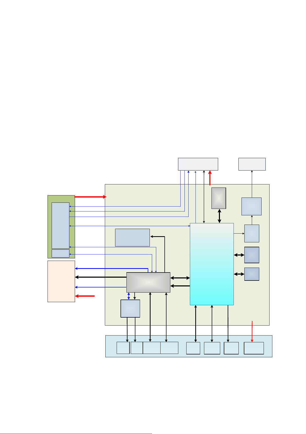
Back-end of main board is the core of back-end ultrasound system, which mainly includes back-end
of main board, CPU module, IO interface board, monitor assembly and control panel. Mainly
Figure 4-5 The Schematic Diagram of Back-end of Main Board
4-4 Hardware Principle
Page 45
implements display interface, user's operation interface, power module controlling interface and all
Main Board
Video S-Video Remote
MUL FPGA
Video
Encoder
Control
Data
VGAUSB Ethernet
CPU
module
System
Monitor
Circuit
Status
Indicator
ECG
kinds of Peripherals Supported interface.
Also provides system monitoring, running status of the monitor system, indicator of system status
and running status of the indicating system via LED.
Function describes as following:
Back-end of main board connects to front-end of main board via PCIE PHY.
The USB on the lateral of Main board is the output of the CPU module.
The relevant signal in HDD of the main board is output of the CPU module.
Back-end of the main board MUL FPGA implements display ports, it also supports display
assembly, video and s-video interface of IO board.
Multifunction FPGA on the back-end of the main board is to implement the REMOTE port
on the IO panel.
Multifunction FPGA on the back-end of the main board is to implement the ECG port on the
IO panel.
The CPU module implements interfaces including USB, Ethernet and VGA on the IO
board.
System monitor circuit connects Multifunction FPGA though smbus.
Multifunction FPGA communicates with ARM by serial port to control transmission
high-voltage, and also implements ARM update by serial port.
FPGA on the power supply module implements the machine power on/off by the switch
signal.
Standby indicator, AC present indicator and working status indicator on the control panel
are output by FPGA.
The control panel implements communication with CPU module by USB.
CPU output the audio signal to the speaker on the front cover of main unit, via audio coder
and audio amplifier.
4.2.3 IO Broad
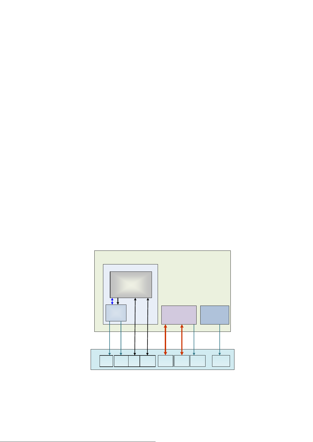
Figure 4-6 Principle Diagram of IO Board
IO board is connected to the main board via connectors in order to implement the user interface
function and indicate if the power is normal.
Hardware Principle 4-5
Page 46
IO board supports Video and S-Video, and the two channels of signal get by Video
Main board
Probe Connected Assembly
Probe board
4D Drive Board
Communication signal
Power
amplication
Voltage
control
Motor driving signal
4D probe Hall return signal
12V
Socket connection
4D
probe
Socket connection
Communication &
Control
Power supply
Ultrasonic signal
Socket connection
Encoder driven by Multifunction FPGA.
IO board supports REMOTE signal, which is obtained by Multifunction FPGA on the main
board.
IO board supports ECG signal, which is obtained by Multifunction FPGA on the main board.
USB signal, Ethernet signal and VGA signal on the IO board are obtained by CPU module
output.
Status indicators of IO board respectively refers to12V, 5V and 3.3V powers are normally
working.
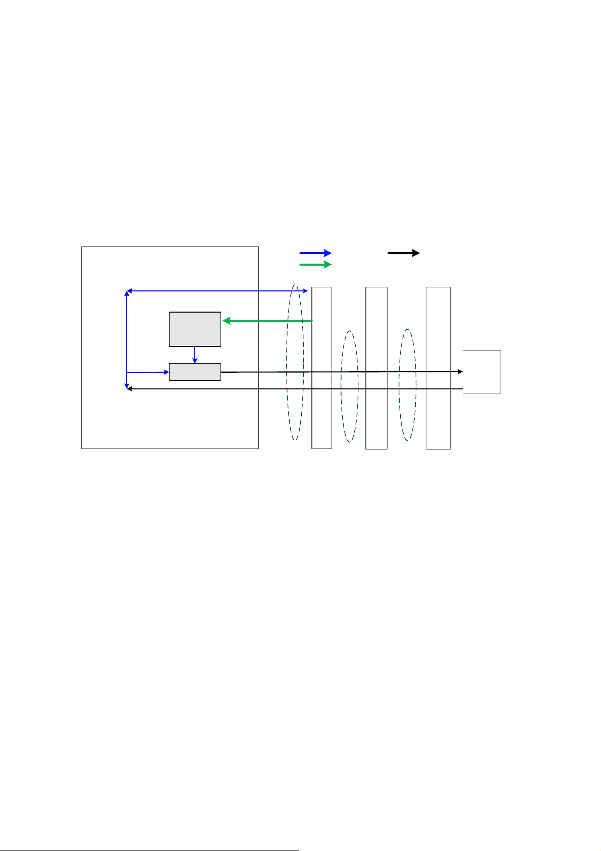
4.2.4 4D Drive Board
Amplifies 4D drive signal power and output signal matching the power requirement to drive the
transducer to the desired position;
Provide 4D Hall signal returning channel.
4-6 Hardware Principle
Page 47
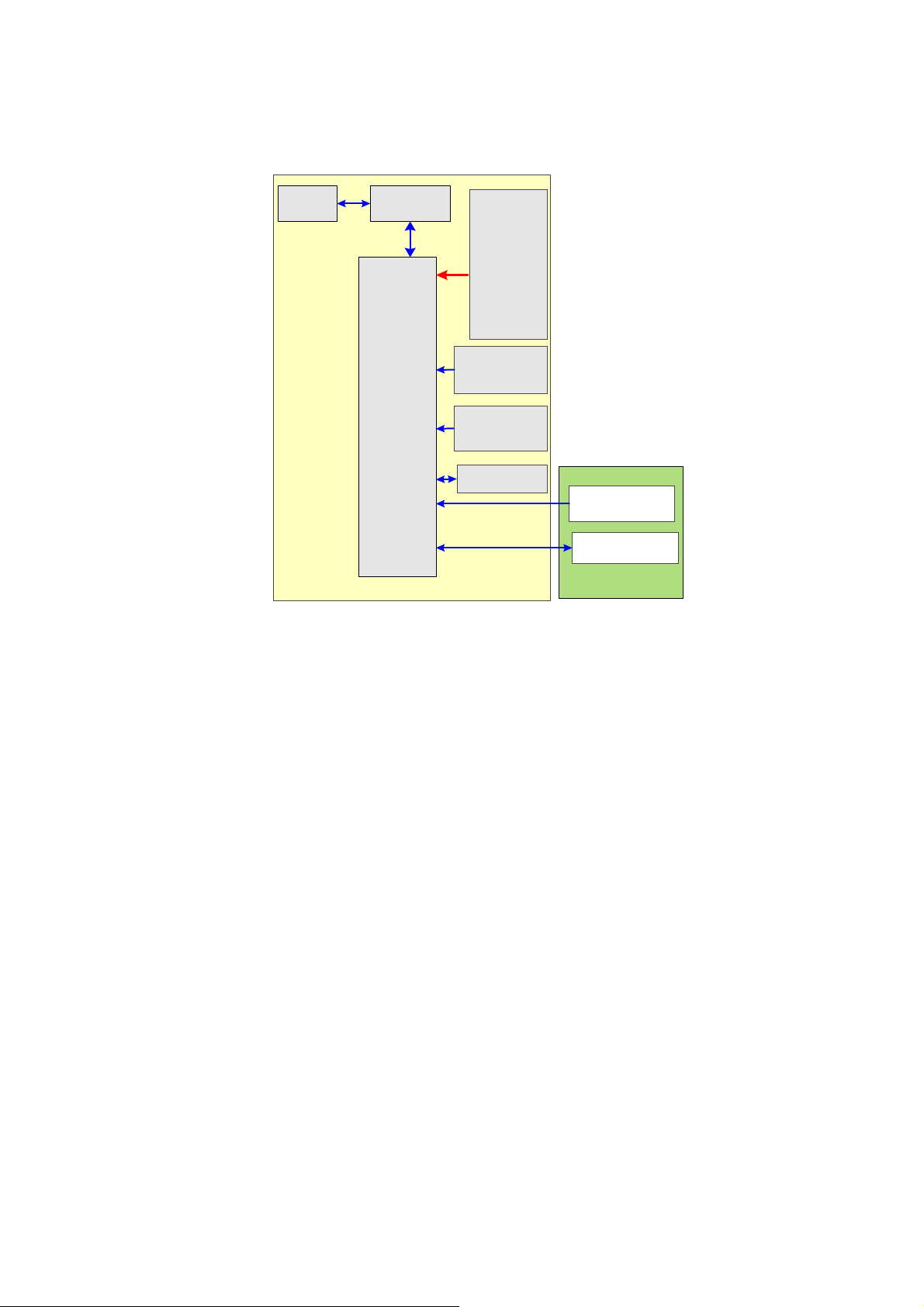
4.2.5 Ultrasound System Monitor
CPU
module
Multifunction
FPGA
System
monitor
curcuit
LPC
SMBUS
Temperature
sensor
Main unit front-
end FPGA
temperature
D12V
D-12V
D-5V
D2.5V
D1.8V
D1.5V
D1.2V
Voltage of
clock
battery
Back-end of main board
CPU module
temperature
Main unit fan
Power supply
module fan
Power supply
module
Figure 4-7 Principle Diagram of Ultrasound System Monitor
Ultrasound system monitor is mainly to monitor every voltage of interior machine and temperature.
Function:
On the back-end of the main board, a special monitor IC is used to monitor signal voltages
and clock battery power that are provided to the main board by the main unit box power
supply module.
The system temperature is detected in three positions: BF FPGA, CPU module and power
supply module.
Monitoring chips control the main unit fan and power supply module fan, and then read the
fan rotating, which send to Multifunction FPGA by smbus, and to PC module by LPC bus.
Hardware Principle 4-7
Page 48
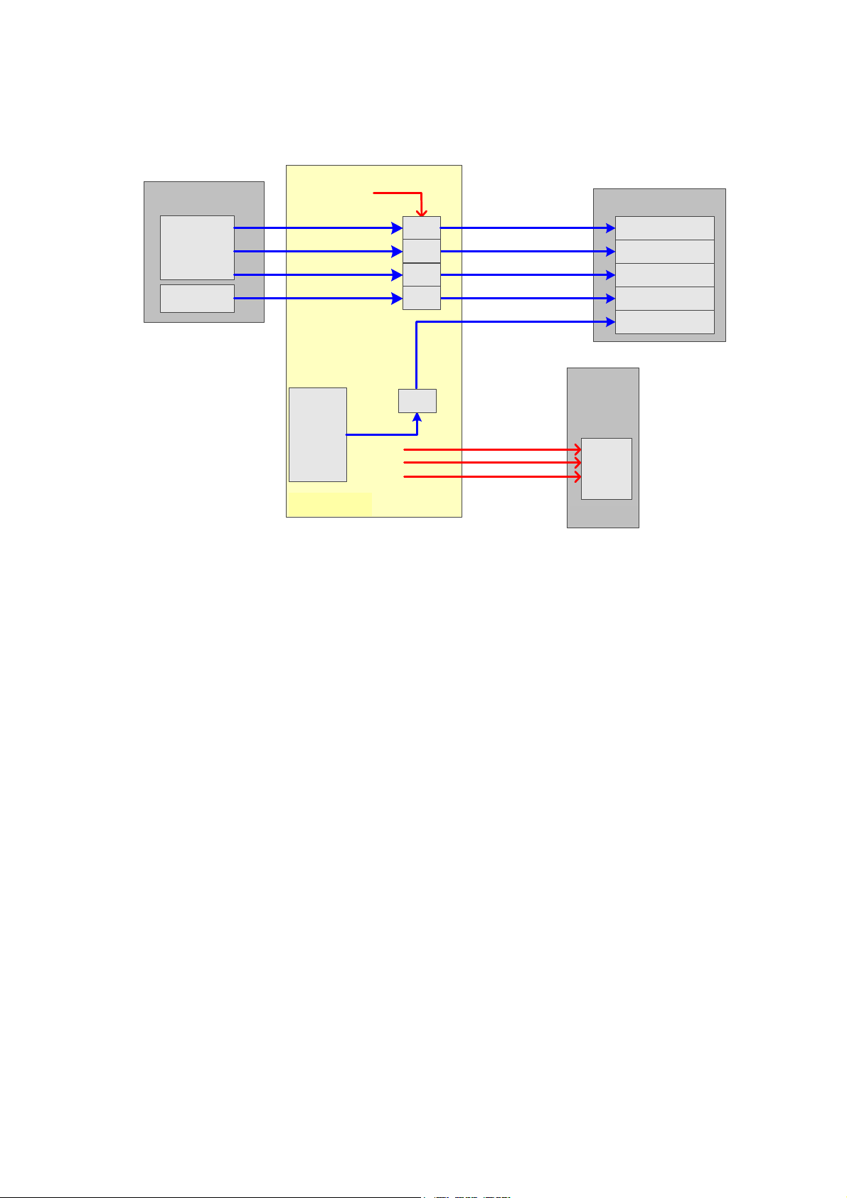
4.2.6 Ultrasound System Indicator
CPU
Module
Main board
Power
status
indicator
Power-on status
indicator
Battery status
indicator
AC supply status
indicator
Standby status
indicator
Power
management
FPGA
HDD indicator
driver
5VSTB_CPU
Control panel
+12V
+5V
3.3V
ARM
driver
Power supply
module
IO Board
driver
driver
driver
Figure 4-8 Principle Diagram of Ultrasound System Indicator
Function describes as following:
There are four power status indicators on the IO panel: three are used for indicators of
+12V, +5V and 3.3V output on the DC-DC power board, the other one is used for reserved
indicator.
There are five indicators on the control panel, in which power-on status indicator is below
the power button.
AC power-on status indicator control is output by the power management FPGA on the
power module.
The hardware indicator control is output by CPU.
The status indicator of battery are controlled by the battery management ARM on the
power module which driven by 5VSTB on the main board.
The status indicators of power-on and standby are both generated by the battery
management FPGA in the power module and driven by 5VSTB on the main board.
4-8 Hardware Principle
Page 49
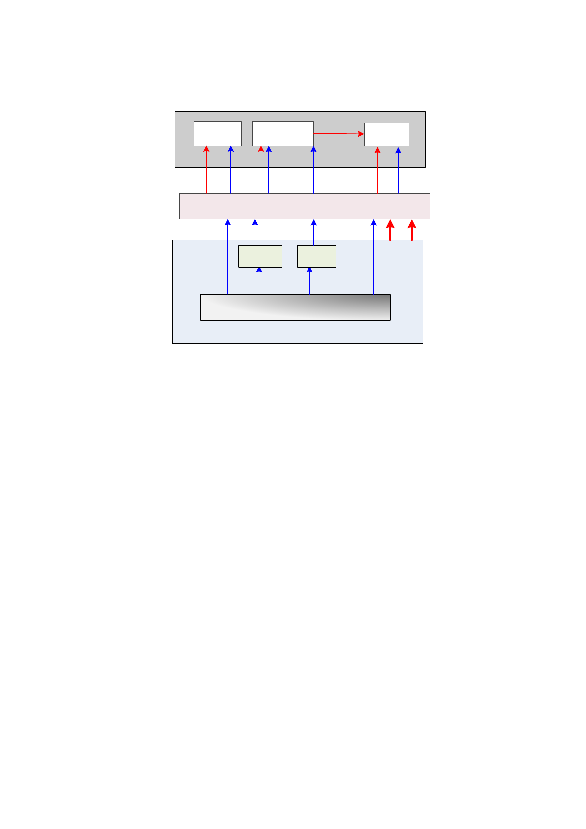
4.2.7 Display
LVDS3.3V
Display
High-voltage
LCD
screen
Parameter
board
I2C
3.3V
Inverter board
ON/OFF
12V
Brightness
control
Main board
IO board
12V 3.3V
Multifunction FPGA
LVDS
I2C
triode triode
Control signal
of switch
Brightness
PWM
ON/
OFF
Brightness
control
Figure 4-9 Principle Diagram of Display
Monitor mainly consists of the inverter board, LCD and the parameter board.
Function describes as following:
The inverter board produces high voltage to illuminate backlight of LCD which is adjusted
by signal control switch and brightness of the IO board output.
Color temperature and Gamma correction data memory in parameter board used matches
LCD so that the corresponding display effect shall be consistent.
Multifunction FPGA generates switch control signal which drives triode to control inverter to
open or shut off high-voltage output.
Multifunctional FPGA generates PWM signal, which drives triode to control output
high-voltage of the inverter to adjust the brightness of the display.
Multifunctional FPGA outputs LVDS digital signal of display, which is sent to screen directly.
Multifunctional FPGA communicates with parameter via 12C signal and supports to adjust
parameters of display.
Hardware Principle 4-9
Page 50
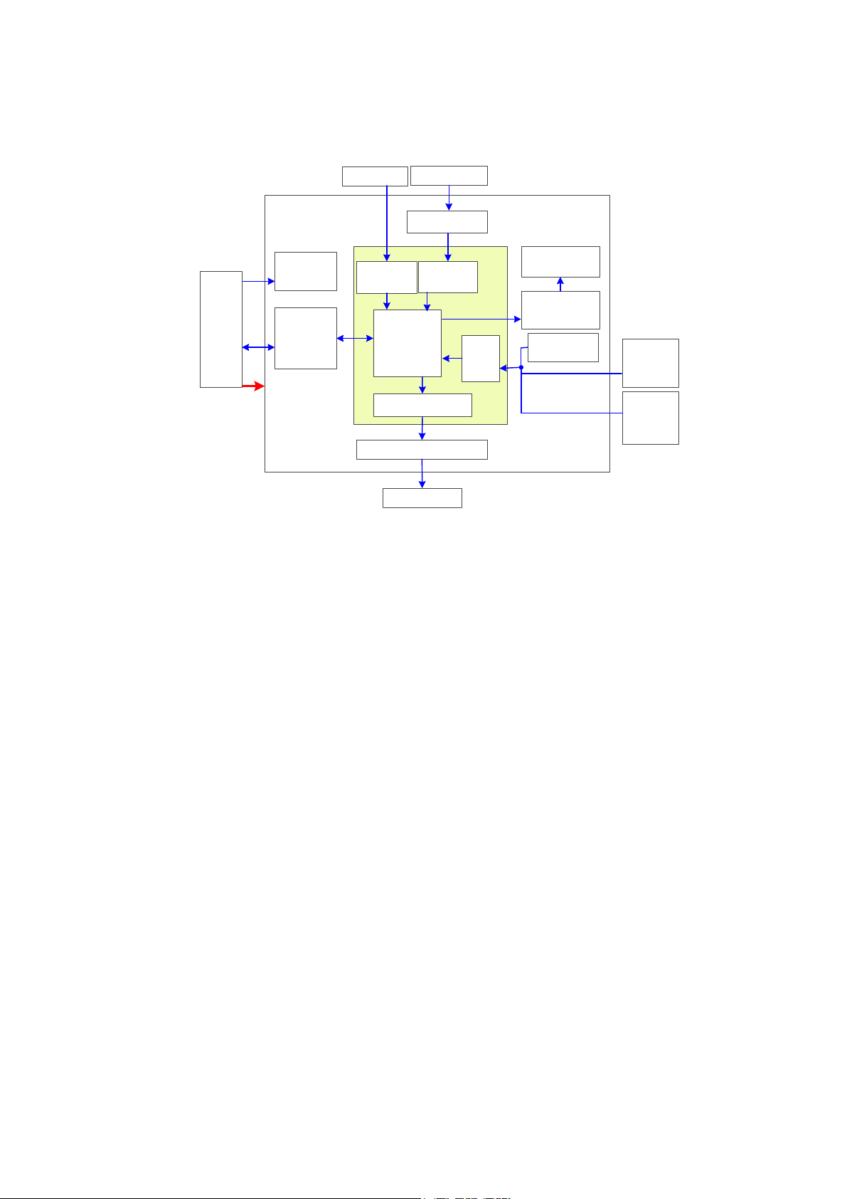
4.2.8 Control Panel
5 status
indicators
TGC board
Trackball
Functional
button
Single-
encoder
board
Key
scan
LED
backlight
driver curcuit
LED
backlight
USB
Interface
chip
ADC curcuit
Buzzer
Buzzer driver curcuit
Main
control
Trackball
scan
TGC
scan
PWM generating
curcuit
FPGA
Control panel PCBA
Main
board
USB
+12V
+5V
Doubleencoder
board
Figure 4-10 Principle Diagram of Control Panel
The control panel PCBA is the core of the control panel which comprises control panel PCBA,
trackball, TGC board, encoder board and buzzer.
Function describes as following:
FPGA is regarded the control panel as a main controller , key, single/dual-encoder,
trackball and TGC.ect are basically scanned by FPGA; Key LED backlight and buzzers
are both controlled by FPGA, and only when FPGA is normal can key LED backlight be on.
Five indicators on the control panel are directly drived by interior of main unit.
The control panel communicates with the CPU module by USB ports.
4-10 Hardware Principle
Page 51
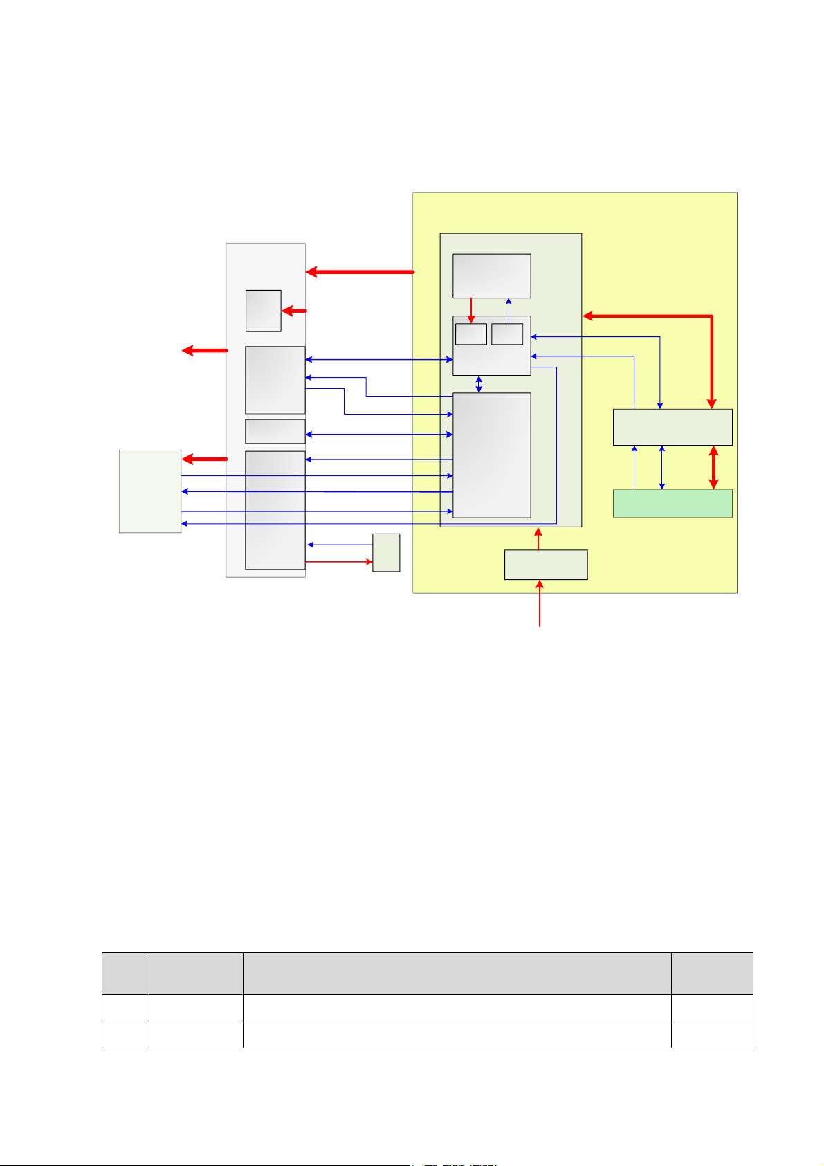
4.3 Power System
AC Input
100-240V~,
50/60Hz
Battery
14.8V,6600mAh
AC-DC board
DC Output 19V/3.95A
Power supply
module
Power
management
FPGA
DC-DC
board
PWR_BTN_N
Main
boar
d
Control
panel
Status indicator
System
monitor
module
Temperature signal
CPU module
Power on/off signal control
ARM
MUL FPGA
ARM control signal
POWER
I2C
PHV
AD DA
Closed signal of the control panel
AC in place
Restart automatically
Status indicator
Control signal
12V、5V
Battery in place
Fan
Fan
monitor
12V
Display
12V
Battery connecting board
I2C
Battery in
place
14.8V,
6600mAh
4D
drive
board
12V
No.
Power
description
Support circuit module or function
Remarks
1
+12V
CPU module, Display, Fan, Control panel, 4D drive board
2
-12V
No use
Figure 4-11 Block Diagram of Power System
The power supply configuration of the system describes as following:
The power supply module can be divided into AC-DC power board, DC-DC power board,
battery and battery connecting board.
High-voltage programmable ARM and power management FPGA are on the DC-DC power
board.
Power output by the power supply module is transmitted to main board, and then it is
output to control panel, 4D drive board and the display by the main board.
Battery is connected to the DC-DC board via the battery connecting board and connecting
cable of BTB sequentially.
4.3.1 Power Output of the Power Supply module and Supporting Function Distribution
Hardware Principle 4-11
Page 52
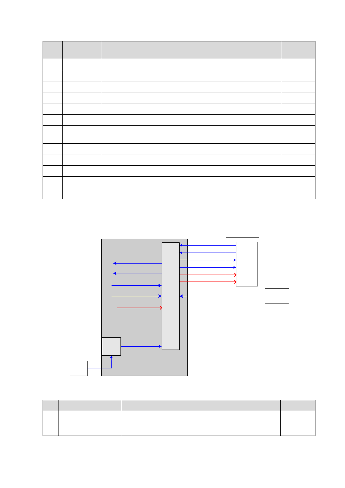
No.
Power
description
Support circuit module or function
Remarks
3
+5V
HDD, Control panel, Front-end of main board, Probe board
4
-5V
Front-end of main board
5
5Vst
CPU module
6
VDD
Front-end of main board, Back-end of main board, Display
7
1V2
Back-end of main board (FPGA core voltage)
8
1V8A
Front-end of main board (receiving chip)
9
1V8
Back-end of main board ( video encoder, FPGA IO voltage ,
DDR2)
10
2V5
Back-end of main board ( video encoder, FPGA IO voltage)
11
+95V
Probe board (high-voltage switch)
12
-95V
Probe board (high-voltage switch)
13
+PHV
Transmitting high-voltage
14
-PHV
Transmitting high-voltage
4.3.2 System Power-on Control
CPU
module
PWR_BTN_N
D12V
SUS_S3_N
SUS_S4_N
CPU_PWR_BTN_N
PWR_OK_N
5VSTB
power
supply
manag
ement
FPGA
AC-DC
board
19V
AC in
place
signal
DC-DC
board
Main
board
Control
panel
PWR_12V_EN_N
PWR_5VSTB_EN_N
PWR_5VSTB_OK_N
PWR_12V_OK_N
AC_IN_STATUS_N
3V3STB
No
Controlling signal
Description
Remarks
1
PWR_BTN_N
The pulse generated by the power button on the control
panel is sent to CPU module through power
management FPGA, to power on the system.
Figure 6-12 Diagram of System Power-on Supported Circuit
Related controlling signal comment:
4-12 Hardware Principle
Page 53
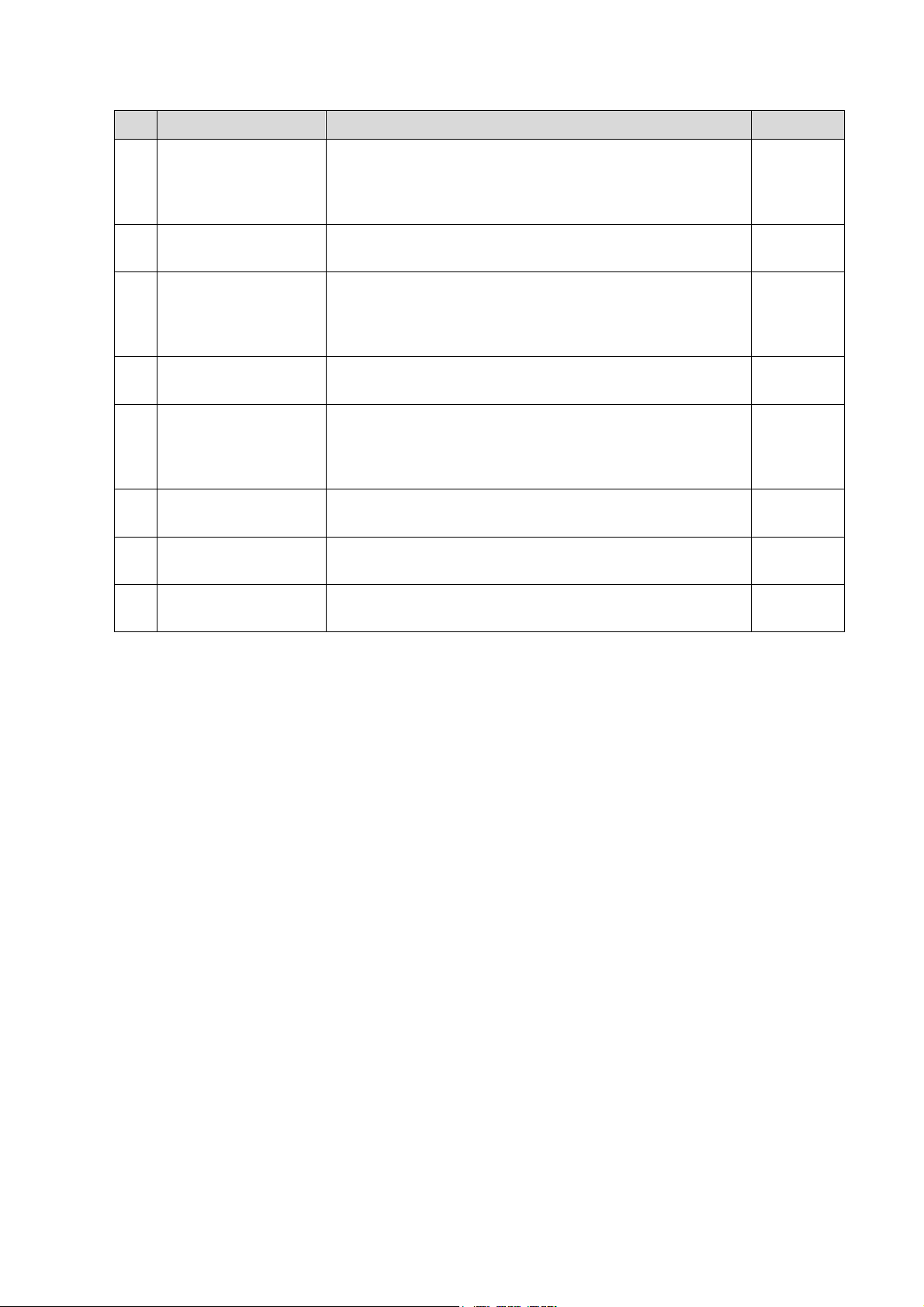
No
Controlling signal
Description
Remarks
2
SUS_S3_N
CPU module output effectively represents that CPU
system has been in the standby status, when 5VSTB
which is controlled by power management FPGA is in the
charging status.
3
SUS_S4_N
CPU module output effectively represents that CPU
system has been in the dormancy status.
4
PWR_OK_N
The output of power supply module is transmitted to the
CPU module by power management FPGA, which
represents the +12V output of power supply module has
been powered on.
5
CPU_PWR_BTN_N
Power management FPGA is transmitted to CPU, which
notifies CPU power on or power off.
6
PWR_12V_EN
The output of power management FPGA is transmitted
to the power supply module, which is used to control
other power of the DC-DC power board except 5VSTB
and 3V3STB to be power-on..
7
PWR_5VSTB_EN
The output of power management FPGA notifies power
to provide 5V standby power.
8
PWR_12V_OK_N
Power status signal; indicate 12V power has been
provided steadily.
9
PWR_5VSTB_OK_N
Power status signal; indicate 5VSTB power has been
provided steadily.
When battery and AC supply, the power supply module always maintains the 3V3STB output,
and supports power management FPGA of the power module to be standby status.
No matter the system is on when AC supply, Power management FPGA will always control
DC-DC power board to output 5VSTB via PWR_5VSTB_EN_N However, when powered by
battery, power management FPGA could control DC-DC power board to output 5VSTB though
PWR_5VSTB_EN_N if only users turn on the system via power button of the control panel.
The detailed flow of power-on is shown as follows:
Hardware Principle 4-13
Page 54
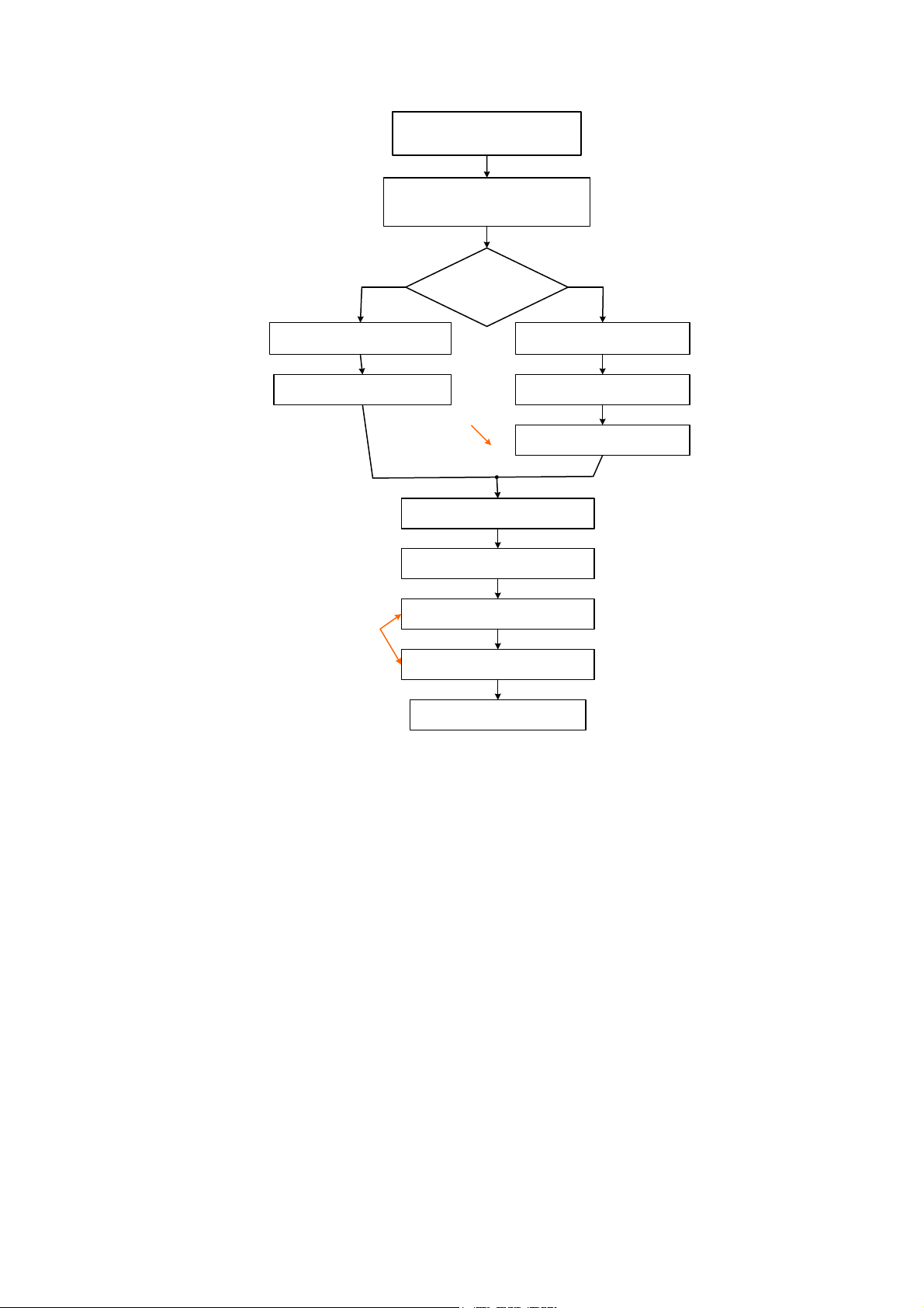
Pressing power button
(Control panel)
Is AC in place?
(Ppower management
FPGA)
NO
Receiving PWR_BTN_N effective
(Power management FPGA)
PWR_5VSTB_EN_N is valid
(Power management FPGA)
5VSTB start-up
(Power supply module)
PWR_5VSTB_OK_N is valid
(Power supply module)
CPU_PWR_BTN_N is valid
(Power management FPGA)
SUS_S3_N and SUS_S4_N
is invalid(CPU module)
PWR_12V_EN is valid
(Power management FPGA)
PWR_12V_OK_N is valid
(Power supply module)
CPU start-up
(CPU module)
12V and +5V start-up
(DC-DC power board)
PWR_OK_N is valid
(Power management FPGA)
YES
Indicating 12V
output of power
module is normal
Indicating
5VSTB_CPU
output of power
module f is normal
Figure 4-2 System Power-on
4-14 Hardware Principle
Page 55

5 Function and Performance
Checking Method
5.1 Instruction
The chapter supplies the method to verify main function and performance of product. This is only
used for reference, not preventive execution.
Function checking and testing of this part shall be carried out by Mindray service engineers and
the user together.
5.2 Checking System Status
5.2.1 System Running Status
1. The ultrasound system can be turned on or off normally, working normally, no any
abnormal noise and phenomenon appear when the system is running.
2. The fan starts to work as soon as the system is turned on, no any abnormal noise appear
in process
3. Check basic system information such as product configuration, options, software version,
etc. Confirm all the information is normal.
4. Check the preset of the monitor, such as contrast and brightness.
5. Check if the time and date are correct, if not, please preset them again.
6. Check the log together with the user to confirm any abnormality or occasional
abnormalities when the system is running.
5.2.2 System Running Status
Check the ambient temperature and humidity. The measurements related to safety features are
particularly sensitive to humidity. If the insulation feature of the system deteriorates due to the
increase of system service time or system malfunctions, the fluctuation range of measurement
results are likely to increase with the increase in humidity.
Function and Performance Checking Method 5-1
Page 56

5.3 General exam
Check the control
panel
Check the monitor
Check DVD
Check peripherals
Check I/O ports
Check ECG module
Procedure
Standard
Check the functions of all keys and knobs
Follow the direction: left to right, and up to down.
All keys and knobs are effective.
Function checking of the trackball
Press the <Freeze> key to enter the Freeze
status.
Press <Measure> to enter into measure
status, do vertical and horizontal
measurement, or do other trackball
operations.
The trackball can be rotated easily and
smoothly, the cursor responds sensitively, the
rotation direction is the same as the direction of
the cursor.
5.3.1 Check Flow
5.3.2 Checking Content
5.3.2.1 Check Control Panel
5-2 Function and Performance Checking Method
Page 57
5.3.2.2 Check the Display
Procedure
Standard
Adjust LCD brightness
Adjust LCD contrast
Display color temperature
adjustment
Click “Cold” or “Warm” in the
[General] page in System Preset
screen.
LCD maintenance
Log in as “Service”, click
[Maintenance] in the Setup
menu, then click [Monitor Test]
to go for the monitor test.
Press “<Fn>+< >”, the brightness increases; and press
“<Fn>+< >”, the brightness decreases.
Press “<Fn>+< >”, the contrast increases; and press
“<Fn>+< >”, the contrast decreases.
The LCD color temperature changes correspondingly.
Click each functional button, the LCD responds correctly,
the standard is as follows
1 .Light-spot: 0; flash point: 0.
2. The adjoining dark dots are no more than 3 pairs, and there is
no adjoining dark dot in image area.
3.There is no adjoining dark dots of 3 or more than 3
4.The dark dots are no more than 7 and those in the image area
are no more than 2
5. The distance between bad dots is no less than 5mm.
Note: image area refers to the red, the background is
black/right.
Procedure
Standard
DVD-R/W Drive
Check if connection is normal
Press <Eject> button on the drive
Perform DVD reading and writing.
The DVD-R/W driver can be ejected smoothly.
Data reading and writing performs normally
without abnormal noise.
Procedure
Standard
Footswitch:
Connect the footswitch connection, and
check the functions of footswitch according
to the functions listed in Key Config.
Press the freeze key (the right key), image is
frozen, the freeze menu is displayed; press the
key again, image is unfrozen.
Press the key (middle key), color printing starts
Press the print key (left key),B/W printing starts
Video Printer:
Check if the video printer and ultrasound
system are correctly connected. Then
check the function of each key.
Press <Print> key, the printer begins to work, no
image print deficiency or degradation.
Switch video output port
Press <Print> key, the printer begins to work, no
image print deficiency or degradation.
Graph/ text Printer:
Check if the graph/text printer and
ultrasound system are correctly connected.
Then check the function of each key.
Press <Print> key, the printer begins to print, no print
deficiency or degradation.
5.3.2.3 Check DVD
5.3.2.4 Check Peripheral Device
Function and Performance Checking Method 5-3
Page 58
bar Code scanner:
Perform code bar scanning when the
ultrasound system is running normally.
The bar code is correctly displayed on the screen.
5.3.2.5 Check ECG Module
Procedure
Standard
Confirm if the ECG module is
configured, then:
Set [ECG] as “On”.
ECG trace is displayed; the heart icon is displayed
at the upper right corner of the screen.
The parameters [Speed], [ECG Gain] can be
adjusted.
ECG signal can be reviewed correctly.
Procedure
Standard
Checking IO ports:
Video/audio interface, USB port have
been verified, remains are:
VGA port
Connect VGA display
Network port
USB port
The contents displayed on the VGA/LCD are the same
as those displayed on the ultrasound system display,
no character and image loss, no color difference, no
fluttering and flicking.
Smooth communication in both network and
connection.
USB port data storage/accessing are normal.
NOTE:
A complete function inspection is described here, do the checking according to the
actual system configuration.
5.3.2.6 Check IO Ports
5.4 Function Checks
5-4 Function and Performance Checking Method
Page 59
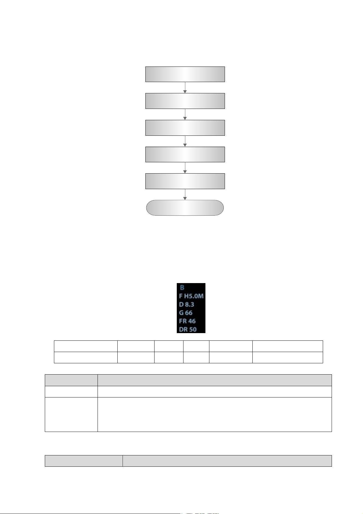
5.4.1 Check Flow
Check each imaging
mode
Check the measurements
Check in cine mode
Check the probe
application
Image & video manage
Record and save the
exam
Display
F
D
G
FR
DR
Image Parameters
Frequency
Depth
Gain
Frame Rate
B Dynamic Range
Adjustment
Items
Control Panel
Gain, Depth, TGC, iTouch, Focus, Frequency
Menu
Frequency, Acoustic power ,Line Density,,ExFOV ,iClear, H Scale, Focus
Position, Focus Number, Persistence, iBeam, Dynamic Range, TSI, Gray
Map,Tint Map,L/R Flip, U/D Flip, Gray Invert ,, , , Lithotrity,FOV, iTouch, Biopsy
Kit.
Procedure
Standard
5.4.2 Checking Content
5.4.2.1 B Mode
In B Mode scanning, the image parameter area in the right corner of the screen will display the
real-time parameter values as follows:
Parameters that can be adjusted to optimize the B Mode image are indicated in the following.
1. Control Panel
Function and Performance Checking Method 5-5
Page 60
2. Menu
Procedure
Standard
Acoustic power
Click [A.power] and rotate the multifunctional knob to adjust.
Press <B>
Enter B mode, and B image displays
Gain adjustment.
Rotate <Gain/iTouch>
Rotate clockwise to increase
Rotate anticlockwise to decrease
The adjusting range is 0-100.The real-time value will be displayed in the
image parameter area in the upper right corner of the screen.
Depth Adjustment
Press <Depth/zoom> to
light on the Depth
indicator, rotate the knob
Rotate clockwise to increase
Rotate anticlockwise to decrease
The adjustable depth values vary depending upon the probe types.
TGC adjustment
Adjust through the
8-segment toggles
Push the toggle to the right to increase the corresponding area
brightness
Push the toggle to the left to decrease the corresponding area
brightness
About 1.5s after the adjustment is finished, the TGC curve disappears.
Focus Position
Adjustment
Press
<Focus/Freq./THI.> to
light on the Focus
indicator, rotate the knob
The focus position will change in correspondence with the knob rotates.
Frequency adjustment
Press
<Focus/Freq./THI.> to
light on the Freq./THI
indicator, rotate the knob
Rotate clockwise to increase
Rotate anticlockwise to decrease
“FR” will be changed relevantly.
iTouch
Press <Gain/iTouch>
iTouch sign will be displayed in the image area to activate image effect
auto optimization.
Click [iTouch] on the image menu to adjust gain value in iTouch mode.
Click [iTouch Brightness] on the image menu to adjust brightness in
iTouch mode.
Image Magnification
Press <Depth/zoom> to
light on the Zoom
indicator, rotate the knob
Rotate clockwise to zoom in the image (max. magnification factor is 10);
rotate anticlockwise to zoom out the image.
Roll the trackball to change position of the magnified image.
Press <Zoom> in zoom status to exit the mode, the current window
returns to the display before zoom.
Press <B>, and then
press
Enter dual mode, and the right image is activated
Press again to switch between the windows
Press <B>, and then
press
Press 4 times, and 4 images will be displayed on the screen with only
one image activated at one time
Press again to switch among the windows
Press <B>
To enter single mode in multiple window mode, or to exit from other
modes.
5-6 Function and Performance Checking Method
Page 61
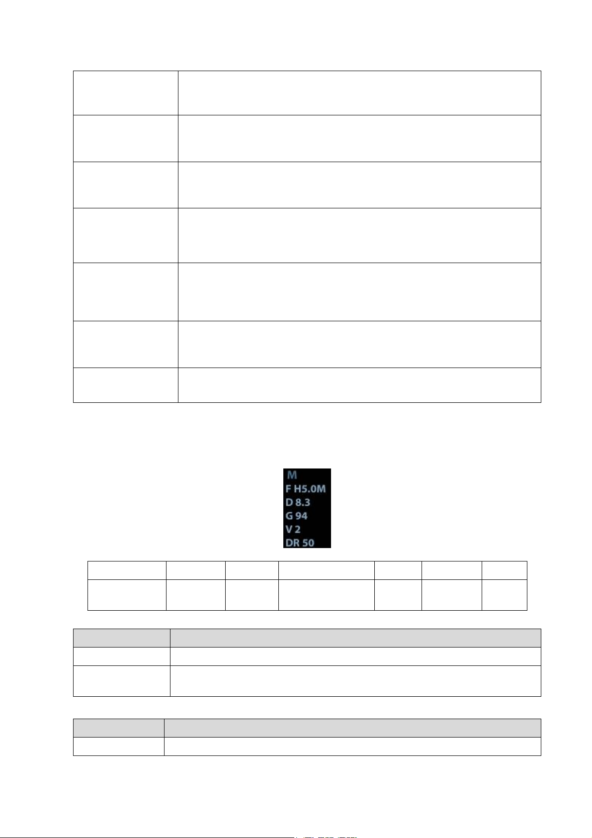
B mode menu
[A.power]
AP value is displayed in real time in the upper part of the screen.
You should perform exams according to actual situation and follow the
ALARA Principle.
Focus
B mode menu
[Focus Number]
Click [Focus Number] and rotate the multifunctional knob to adjust (B mode
image has max. 4 focus )
The focus position symbol is displayed on the right side of the image.
FOV (Field of View)
B mode menu->
[FOV]
Click [FOV] and rotate the multifunctional knob to adjust
Dynamic Range
B mode menu->
[Dynamic Range]
Click [Dynamic Range]; rotate the multifunctional knob to adjust, the real
time value will be displayed on the image parameter area in the upper right
of the screen. As the dynamic range increases, the darker the image and the
contrast, as well as the noise may increase.
Line Density
B mode menu->
[Line Density]
Click [Line Density], and rotate the multifunction knob to adjust the
parameter.
The higher the line density, the higher the resolution, and the lower the frame
rate.
iClear
B mode menu->
[iClear]
Click [iClear] to adjust, off represents no iClear is turned on, and the bigger
the value the stronger the effect. The bigger the value the more clearly the
profile of the image.
B mode menu->
[U/D Flip]/[L/R Flip]
B mode menu-> [U/D Flip]/[L/R Flip]
Click [Rotate] to adjust.
5.4.2.2 M Mode
Display
V
IP 6
DR
G
F
D
Image
Parameters
M Speed
M IP
M Dynamic
Range
M Gain
M
Frequency
Depth
Adjustment
Items
Control Panel
Frequency, Gain, TGC, Depth
Menu
Frequency, Acoustic Power Focus Position, Edge Enhance, M Soften, Speed,
Dynamic Range, Gray Map, Tint Map, Display Format.
Procedure
Standard
Press <M>
Press <M> on the control panel, and roll the trackball to adjust the sampling
In M Mode scanning, the image parameter area in the right corner of the screen will display the
real-time parameter values as follows:
Parameters that can be adjusted to optimize the M Mode image are indicated in the following.
1. Control Panel
Function and Performance Checking Method 5-7
Page 62

line.
Then press [M]
again.
Press [M] on the control panel again to enter M Mode, then you can observe the
tissue motion along with anatomical images of B Mode.
Press <Update>
To switch between the active B image and frozen B image.
Tips:
a) Adjustment of the depth, focus position or TGC to the B Mode image will lead to
corresponding changes in M Mode image.
b) For details of other control panel adjusting parameters, please refer to descriptions in B
mode
5-8 Function and Performance Checking Method
Page 63
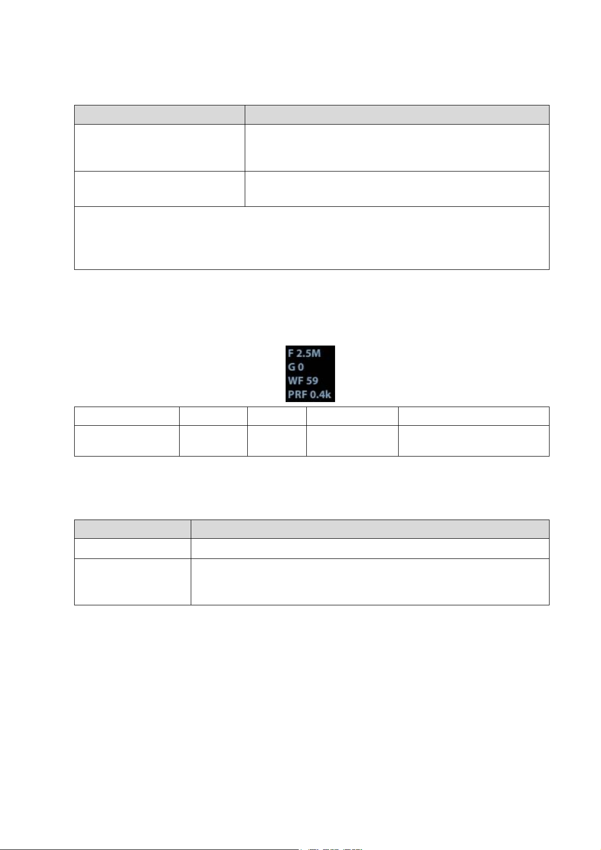
2. Menu
Procedure
Standard
Speed
B mode menu-> [Speed]
Click [Speed], and rotate the multifunction knob to adjust the
parameter.
The lower the value the faster the refreshing.
Display Format
M mode menu-> [Display Format]
There are 4 formats available for image display: L/R, V1:1,
V1:2, Full.
Tips:
a) During M Mode scanning, frequency and acoustic power of the probeare synchronous with
that of B Mode.
b) Refer to B mode for more details.
Display
F G WF
PRF
Image Parameters
Frequency
Color
Gain
Color Wall Filter
Pulse Repetition Frequency
Adjustment
Items
Control Panel
Color Gain、Frequency、Depth、Steer, Scale
Menu
Frequency、Acoustic Power, Persistence, Line Density,Packet Size,
Priority , B/C Align, Smooth, Wall Filter,Scale, Baseline,Invert,Color Map、
Dual Live
5.4.2.3 Color Mode
In Color Mode scanning, the image parameter area in the right corner of the screen will display
the real-time parameter values as follows:
Parameters that can be adjusted to optimize the Color Mode image are indicated in the
following.
Function and Performance Checking Method 5-9
Page 64
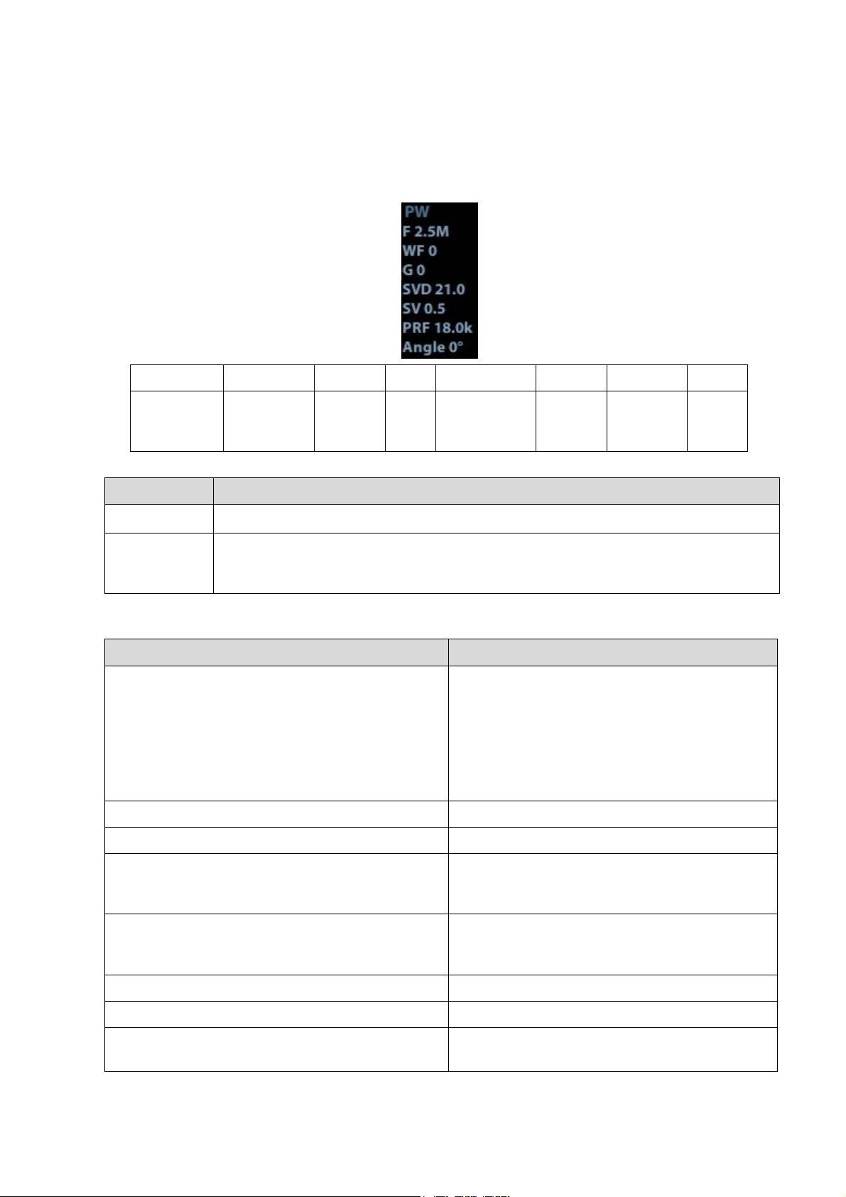
Display
F
G
WF
PRF
SVD
SV
Angle
Image
Parameters
Frequency
PW/CW
Gain
Wall
Filter
Pulse
Repetition
Frequency
Sample
Volume
Depth
Sample
Volume
Size
Angle
Adjustment
Items
Control Panel
Gain、Frequency
Menu
Frequency, Acoustic Power ,Scale, Wall Filter, Speed, Duplex/Triplex, SV, Quick
Angle, Angle, Invert, Baseline, Trace Area, T/F Res, Audio, Auto Calc, Auto Calc
Cycle, Auto Calc Para, HPRF, Dynamic Range, Gray Map, Tint Map, Display Format
Procedure
Standard
Press [Freeze] key to freeze an image, and
the [Cine] key indicator lights on. The system
automatically enters the manual cine
status.(Precondition: set “Status after Freeze”
to be “Cine”)
Press iStation, click [Review] or press
<Review> to open the cine file
Cine Review status
To enter cine auto cine review status.
Roll the trackball
Manual cine review
Click image menu->[Auto Play]
Activate auto cine play status
Manually review the images until the frame which
you want to set it as start point, and then click [Set
First Frame] to set a start mark.
Set first frame:
Manually review the images until the frame which
you want to set it as end point, and then click [Set
End Frame] to set an end mark.
Set end frame
Click [Auto Play]
The cine is played within the setting region.
Then press the [Cine] key again.
Cine review stops
Press the <Freeze> key to defreeze the
image.
<Freeze> backlight is off, the image
returns to the scanning process and exits
5.4.2.4 PW Mode
In PW Mode scanning, the image parameter area in the right corner of the screen will display
the real-time parameter values as follows:
Parameters that can be adjusted to optimize the PW Mode image are indicated in the following.
5.4.2.5 Cine Review
5-10 Function and Performance Checking Method
Page 65
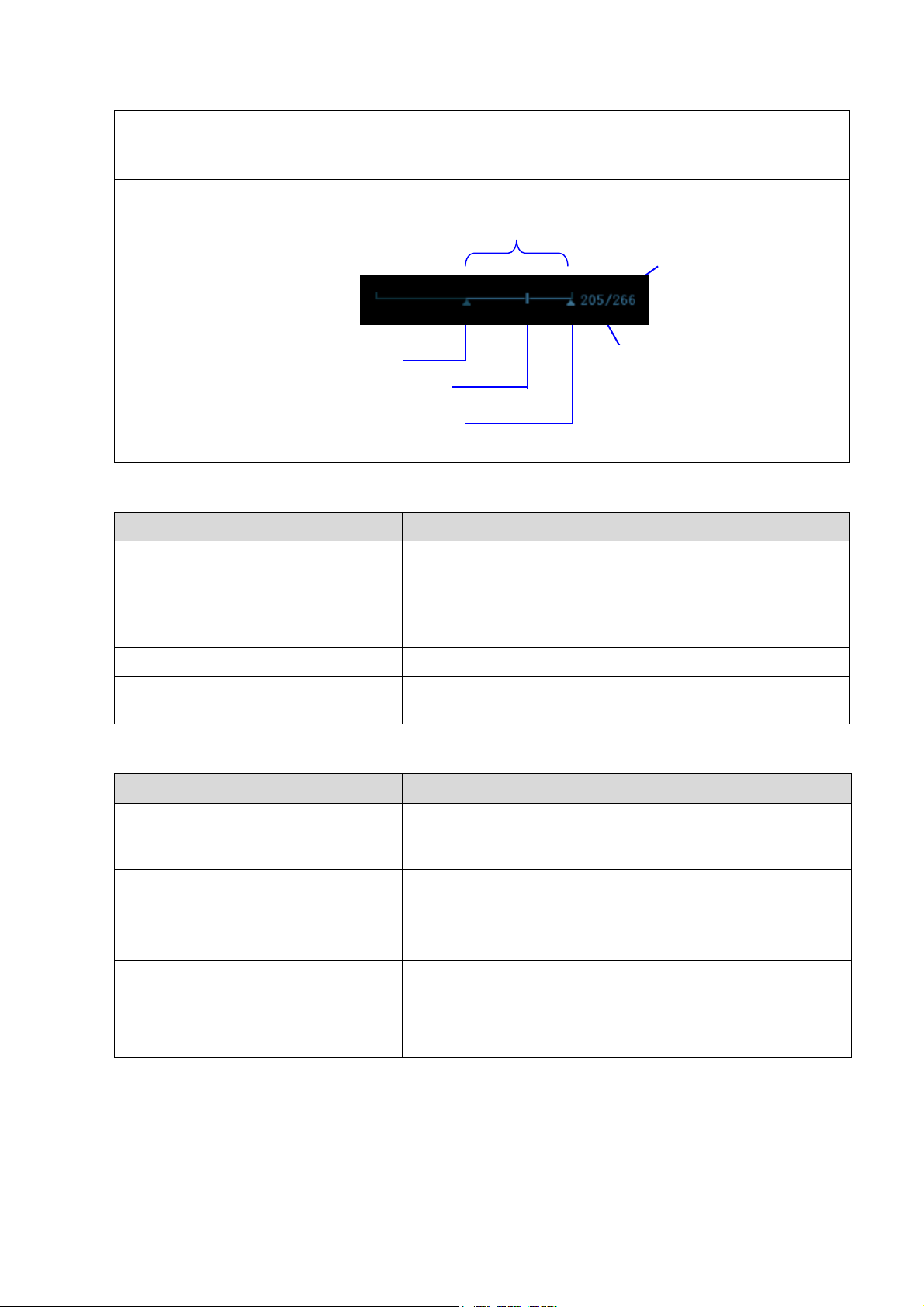
Press <ESC> or <Cine>
cine review.
The images are still frozen but the system
exits cine review.
5.4.2.6 Measurement
Procedure
Standard
In B mode
Press <Measure>:
Press <Caliper> key
Enter the application measurement mode.
Enter the general measurement mode.
Click any 1-2 measurement items, the measurement
results will be displayed below the image
Press <ESC> or the same key again.
Exits measurement.
Perform similar operations in other
modes
Application measurement functions are related to certain
application software packages.
Procedure
Standard
Press <Save1/2> in image scanning
process (preset already).
The image will be saved to corresponding patient database
and the saving icon will be displayed in the right of the
screen.
Press <Review>
Click [Exit] on the Review
screen; or press <Review> or
<ESC>.
To enter Review:
To exit Review:
Press <iStation> to enter Patient
information management (iStation
page)
Saved images and information for the patient can be
checked here, and you can:
Backup/ Restore
Send to (DICOM or network storage)
Auto Review Region
Start mark
End mark
Playback mark
Current
frame
Total frames
5.4.2.7 Patient Information Management
Function and Performance Checking Method 5-11
Page 66
5.5 Performance Test
Resolution
Detection depth
Geometric Position
Accuracy
Blackout area test
Record the exam
images
NOTE:
The image used here is only for reference, stick to the image effect in the real
situation.
5.5.1 Test Process
5.5.2 Test Content
Requirements:
1. Display: set the contrast and brightness at the clinical application value (or the default status)
2. Operation environment: dark room, simulating the clinical application environment.
3. Scanning techniques: contact the probe with the acoustic window of the phantom, no spacing
nor pressing.
Tips:
For the testing phantoms, please refer to Appendix B.
5.5.2.1 Resolution
transverse resolution
Test Step:
1. Cover the scan surface of the phantom with water or couple gel, gently contact the probe with
the scan surface, making the transverse resolution testing targets to be displayed around the
midline of the image.
2. Adjust the focus point focuses at the position where the transverse resolution testing targets
are displayed.
3. Adjust parameters like gain, dynamic range, TGC, making the background tissue unseen, just
displaying the target image clearly.
5-12 Function and Performance Checking Method
Page 67
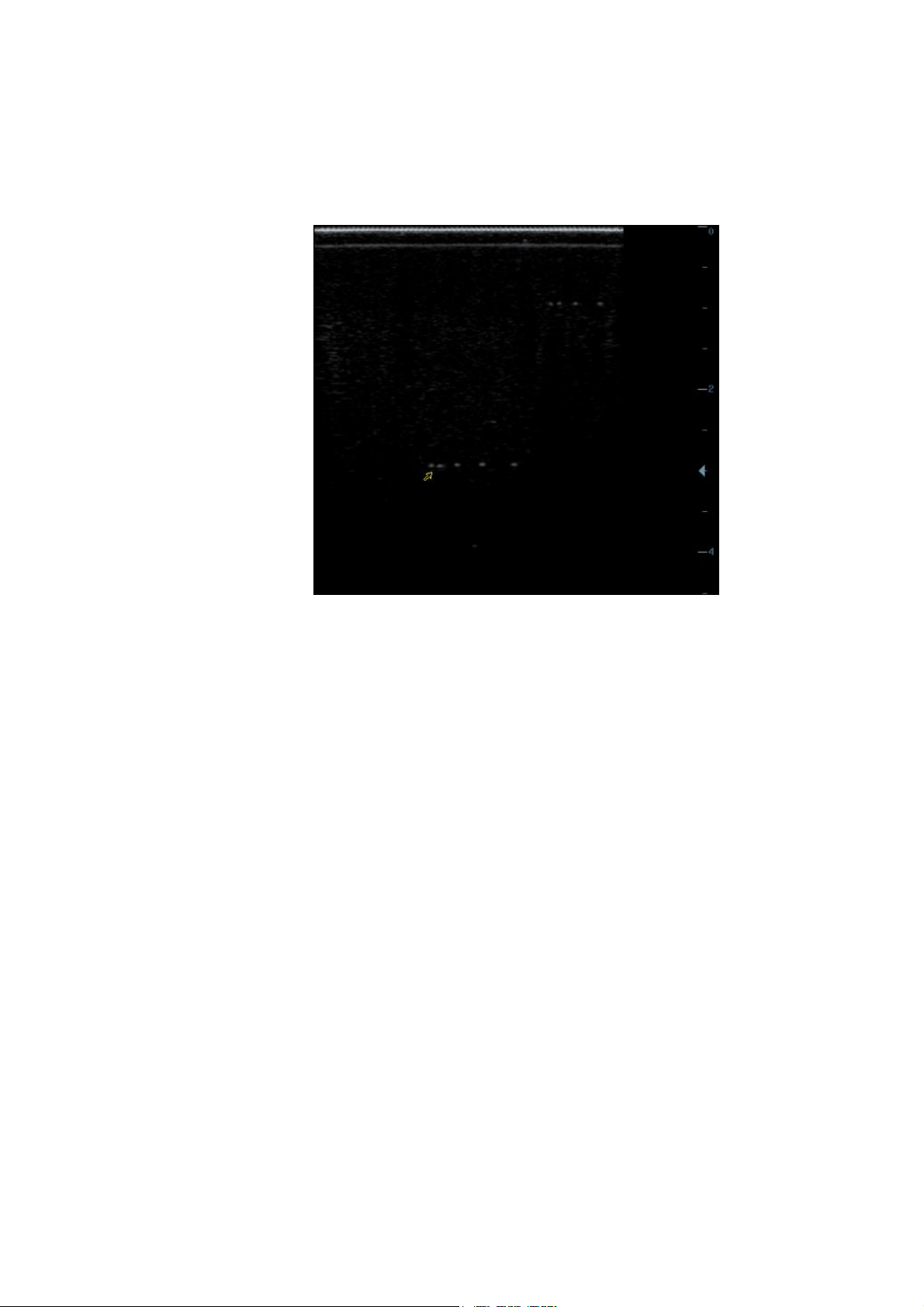
4. In condition that the transverse resolution testing targets are horizontally displayed, record the
minimal distance of two targets that can be clearly recognized.
5. Repeat the operation above for the transverse resolution testing targets at other depths.
As shown in figure below.
Axial resolution
Test Step:
1. Cover the scan surface of the phantom with water or couple gel, gently contact the probe with
the scan surface, making the longitudinal resolution testing targets to be displayed around the
midline of the image.
2. Adjust the focus point focuses at the position where the longitudinal resolution testing targets
are displayed.
3. Adjust parameters like gain, dynamic range, TGC, making the background tissue unseen, just
displaying the target image clearly.
4. Record the minimal distance of two longitudinal resolution testing targets that can be clearly
recognized.
5. Repeat the operation above for the longitudinal resolution testing targets at other depths.
Function and Performance Checking Method 5-13
Page 68
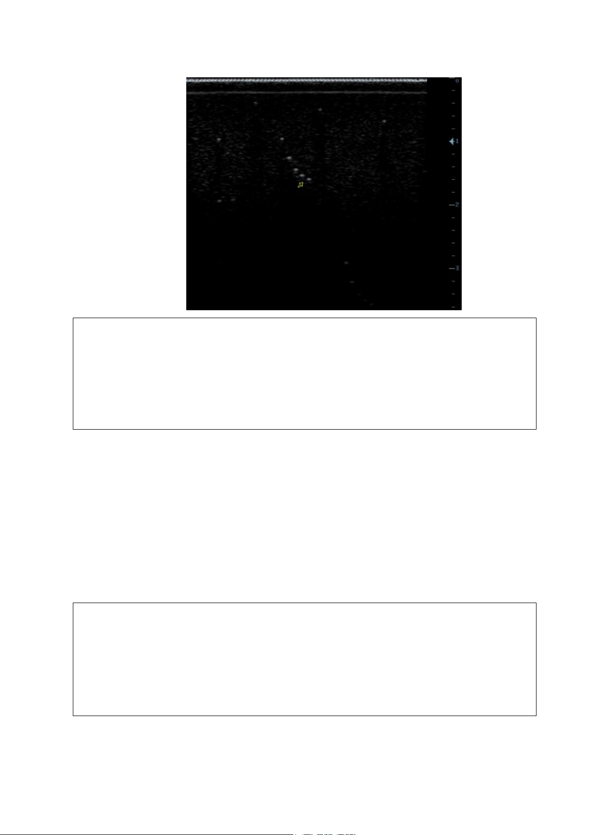
NOTE:
1.
When using the convex probe, keep the transverse resolution testing targets to
be displayed near the midline.
2.
When using a linear probe with steer function, do not turn on the steer function
when perform the transverse resolution test.
3.
Zoom in the region where the targets located if necessary.
4.
The diameter of the target point at a certain depth is equal to the transverse
resolution at the depth.
NOTE:
1.
Increasing the gain will also increase the noise, and echo may be covered.
2.
When using a linear probe, please completely contact the probe with the scan
surface, no side clearance is allowed.
3.
When using a convex or phased-array probe, make the axis targets to be
displayed at the middle of the scanning image.
4.
When system is not frozen, the fast field target information may be similar to
that of the noise, do not use this target.
5.5.2.2 Maximum Depth
Test Step:
1. Cover the scan surface of the phantom with water or couple gel, gently contact the probe with
the scan surface
2. Set the system display depth according to the expected maximum available depth of the probe
in use.
3. Adjust the focus point to the deepest, and AP at the maximum value.
4. Set gain, contrast, TGC at a greater value, but no halation nor defocus is allowed.
5. Record the depth of the furthest target (the target can be seen clearly).
As shown in figure below.
5-14 Function and Performance Checking Method
Page 69
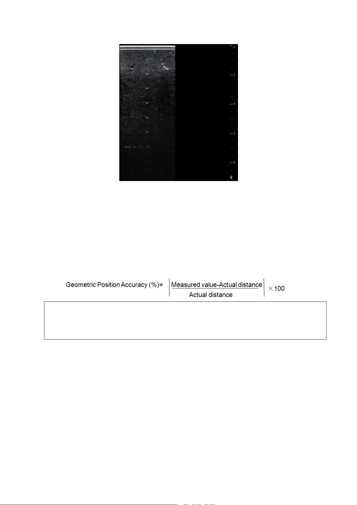
NOTE:
1.
The measurement caliper should be positioned at the upper edge of the target,
not the middle nor the lower edge.
2.
The scanning plane should be vertical to the target line, that means the
scanning plane is parallel with the cross-section of the phantom
5.5.2.3 Geometric positioning accuracy
Longitudinal geometric positioning accuracy
Test Step:
1. Do adjustments as the way in testing the maximum depth.
2. Record the distance by 20mm each segment on the longitudinal targets line using the
measurement caliper;
3. Select the value with the greatest error (to 20mm), calculate the accuracy using the formula
below
As shown in figure below.
Function and Performance Checking Method 5-15
Page 70
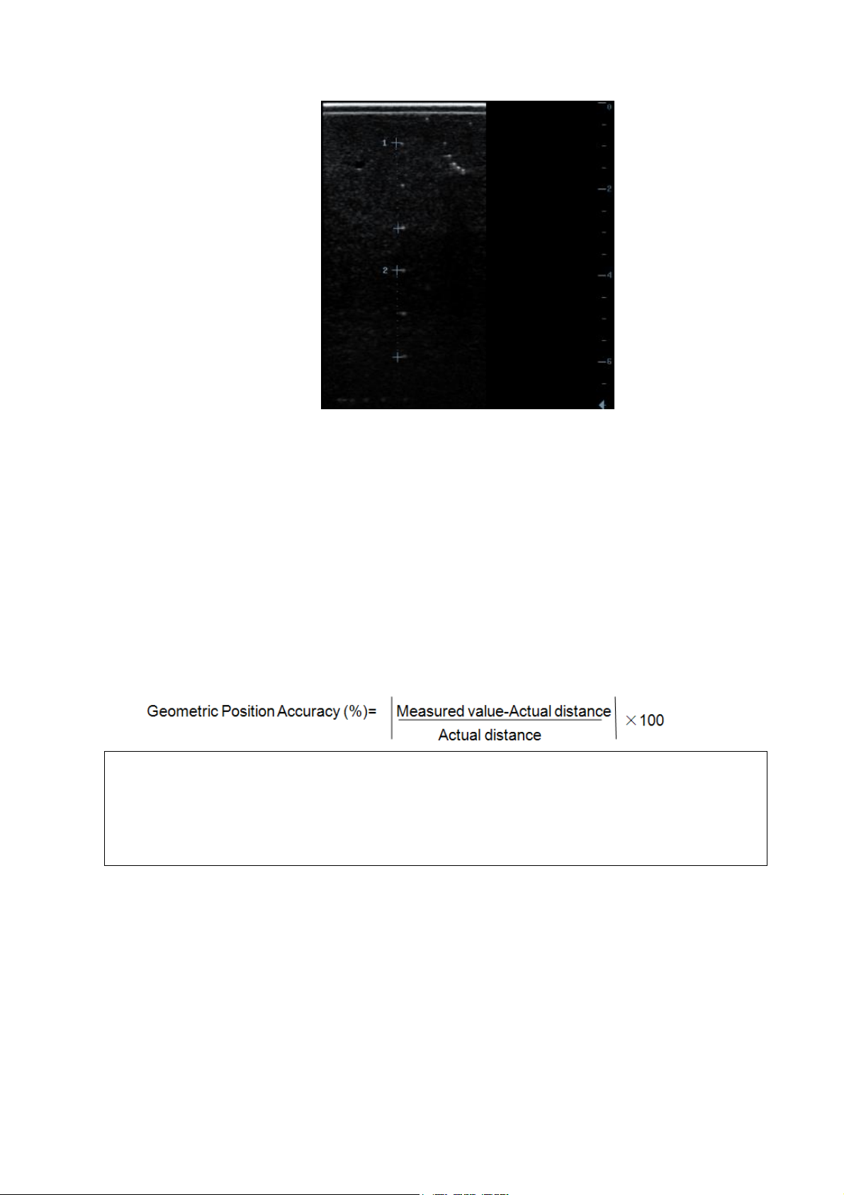
NOTE:
1.
When using a linear probe, record the transverse distance by segment.
2.
When using a convex probe, all transverse targets should be displayed
integrally in an image.
3.
The measure caliper should be posited at the upper side or lower side of the
target center.
Transverse geometric positioning accuracy
Test Step:
1. Cover the scan surface of the phantom with water or couple gel, gently contact the probe with
the scan surface
2. Adjust the depth, making the transverse targets to be displayed in the image.
3. Adjust the focus point to be posited beside the transverse targets (the standard is not clear)
4. Adjust parameters like gain, TGC, making each transverse targets to be clearly displayed.
5. Record the distance by 20mm each segment on the transverse targets line by using the
measurement caliper
6. Select the value with the greatest error (to 20mm), calculate the accuracy by using the formula
below
As shown in figure below.
5-16 Function and Performance Checking Method
Page 71
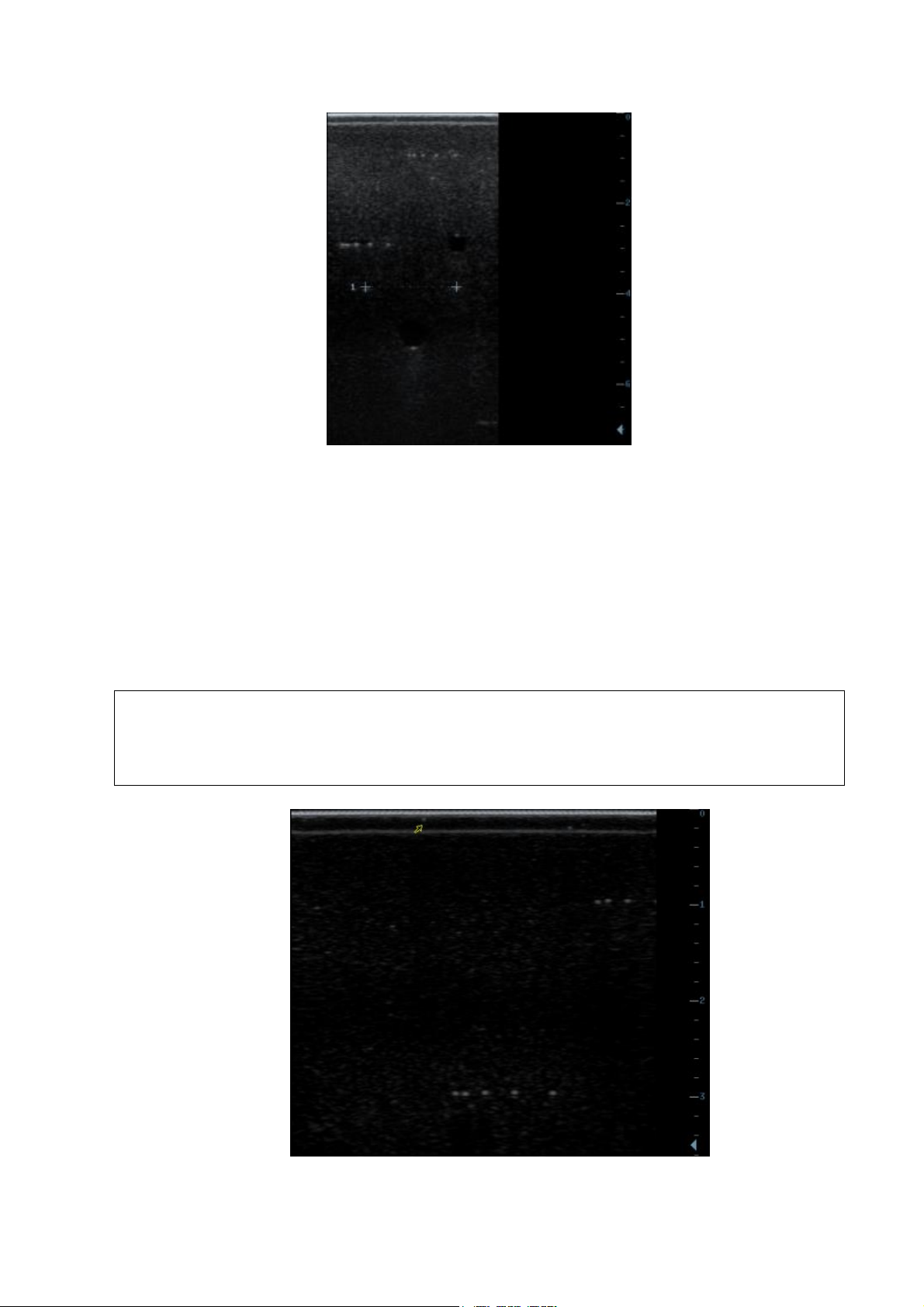
NOTE:
1.
When using a linear probe, please completely contact the probe with the scan
surface, no side clearance is allowed.
2.
For convex probe, the targets in the blackout area should be positioned on the
midline of the scanning plane.
5.5.2.4 Blackout Area
Test Step:
1. Cover the scan surface of the phantom with water or couple gel, gently contact the probe with
the scan surface
2. Adjust the depth at a lower value, and set the focus at the nearest place to the scan surface.
3. Decrease the value of parameters like AP, Gain until the background noise just can be seen.
4. Record the smallest depth of the target that can be seen clearly, that value is the blackout area
value.
As shown in figure below.
Function and Performance Checking Method 5-17
Page 72

Page 73
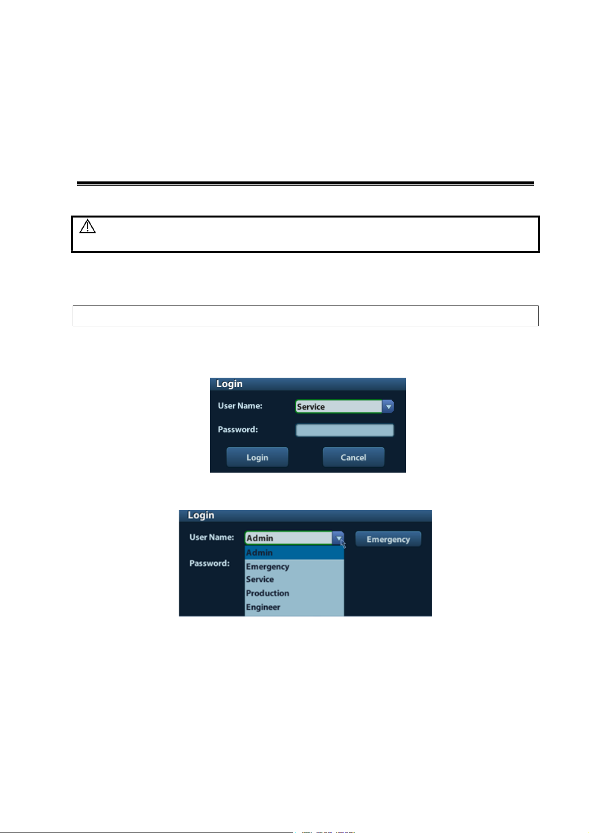
6 Software Upgrade and
NOTE:
Log on the system with the identity of Service before perform system maintenance.
Maintenance
WARNING: DO NOT directly remove a USB memory device; otherwise, the USB
memory device and / or the system may be damaged.
6.1 Enter the Maintenance Window
To log on the system:
1. When access control function has not been activated: press “Ctrl+/” to show the Login dialogue
box, and then select the Service as the user name.
2. When access control function has been activated already: press “Ctrl+/” when the Login
dialogue box is displayed, and then select the Service as the user name.
3. Press <Setup> key to open the Setup menu, click [Maintenance] and then select the target
items to perform the maintenance respectively.
Software Upgrade and Maintenance 6-1
Page 74
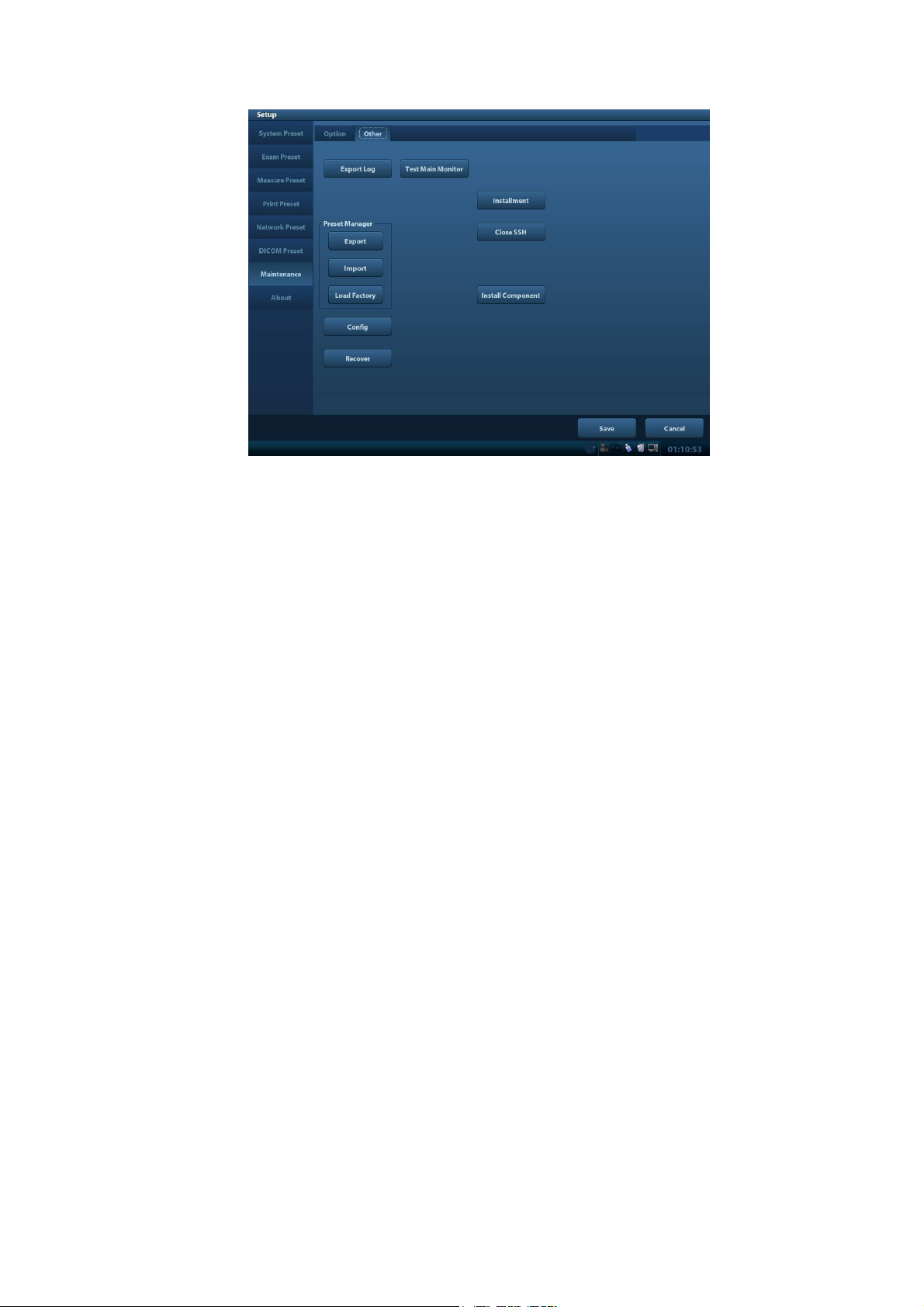
6.2 System Software Installation/ Restoration
Refer to recovery guide.
6.3 Installation of Optional Devices
1. Copy the optional devices to the U disk, then insert it to the USB port of the ultrasound system;
2. Enter [Preset], click [Maintenance] to enter [Option] menu to select the option module to be
installed.
6-2 Software Upgrade and Maintenance
Page 75
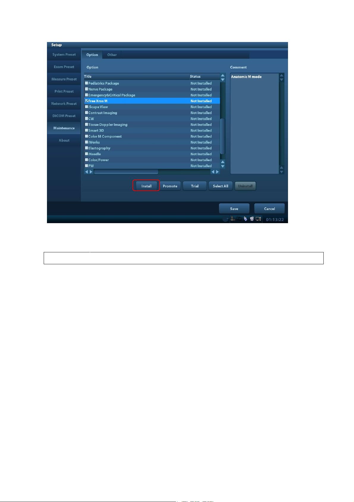
Note:
After all modules are installed, please go to the previous interface to confirm.
3. Click [Install]. Select key file from the dialog box, and then click [OK].
4. The options become Installed after the key files are installed. The corresponding function is
activated after returning from preset.
Trial: select the corresponding software package, and then click [Trial].
Note: for each component, you can activate trial version only once. The trial lasts 180 days for each
key.
Promote
1. Click [Promote]. The following image appears:
Software Upgrade and Maintenance 6-3
Page 76
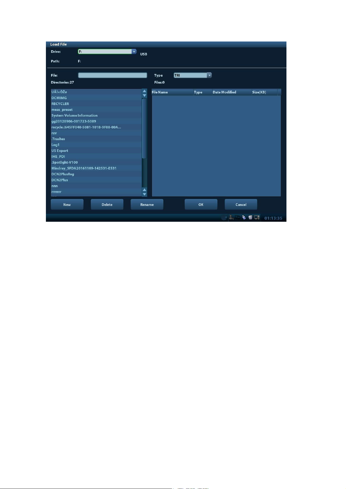
Note: the promotion function is only applied to the uninstalled key. If the optional key is installed, the
promotion function is disabled.
2. Select the key to be promoted.
3. Click [OK] to complete the promotion.
Note: it is unavailable to use promotion for multiple optional keys. For the optional key which is
promoted, it can also be installed. The promotion lasts 365 days for each key.
Uninstalling
1. Select the software package to be uninstalled from option list.
2. Click [Uninstall] and it pops up the [Confirm] dialogue box. Click [OK];
6-4 Software Upgrade and Maintenance
Page 77
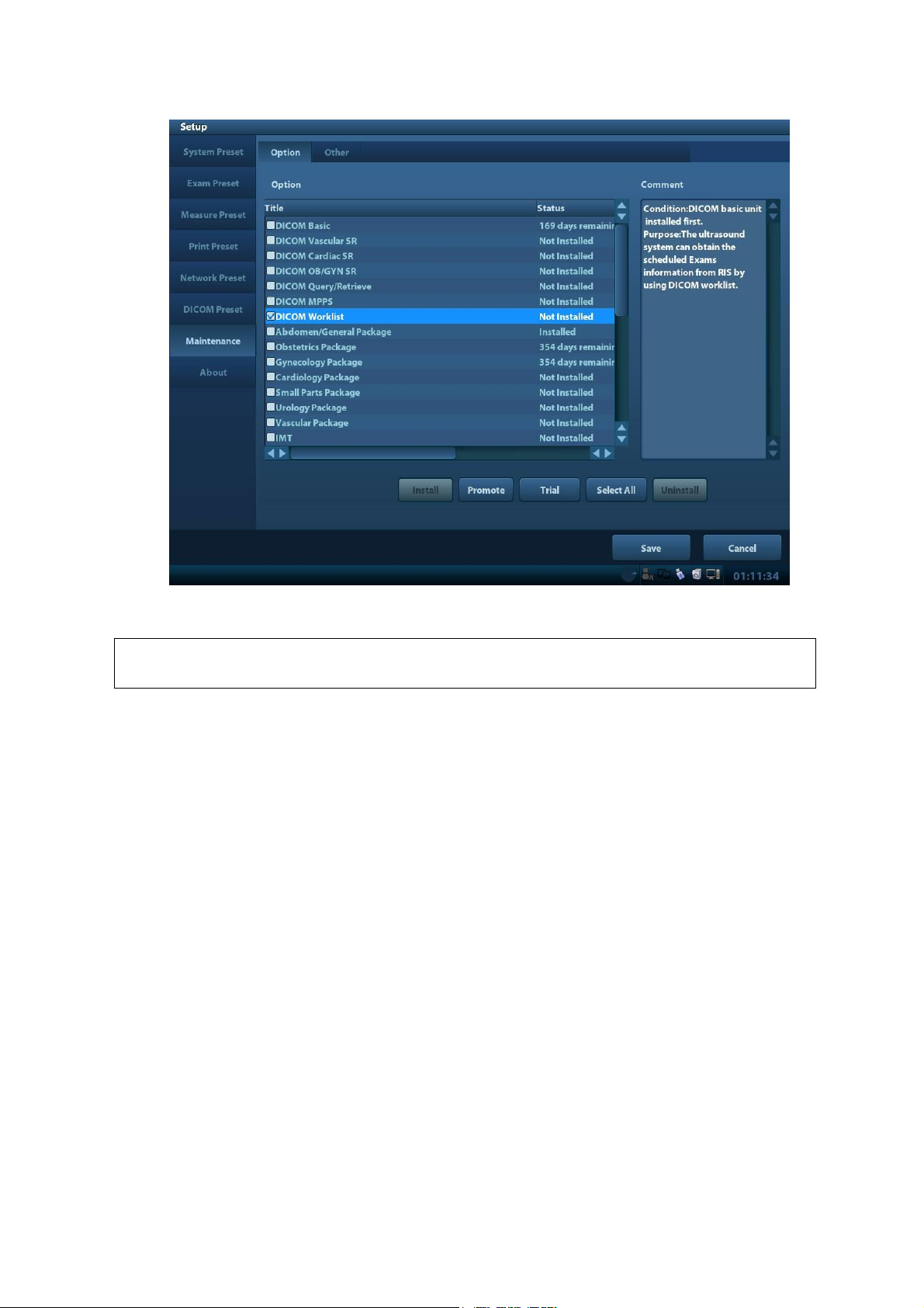
Note:
The uninstalling function is exclusive to internal users. The service engineers must
log in the system with the account of Service, and then conduct the uninstallation.
Return to the system preset interface. The option status changes into Uninstalled.
6.4 Data Backup and Storage
6.4.1 Manage Settings
Press <Setup> to open the Setup menu, click [Other] to open the Manage Setting interface. System
preset can be performed here. Image parameters can be exported, imported or restored to factory.
Software Upgrade and Maintenance 6-5
Page 78
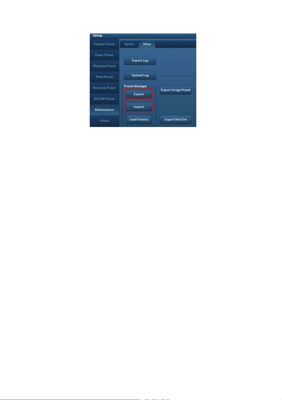
6.4.1.1 Back up the Preset Data
1. On Manage Settings page, Click [Export] to open the [Export Data] dialogue box.
2. Select the path to save data.
3. Click [OK], a progress bar will appear and the preset data of the selected items will be exported
to the specified path.
6.4.1.2 Restore the Preset Data
1. On Manage Settings page, Click [Import] to open the [Import Data] dialogue box.
2. Select the path of the preset data.
3. Click [OK], a progress bar will appear and the preset data will be imported to the specified path.
Note: If selecting [Load factory],it will restore the system to the factory setting, but the
[Region],[Admin] , [Network Preset] and [DICOM Preset] cannot be restored.
6.4.2 Patient Data Backup and Restore
6.4.2.1 Patient Data Backup
1. Press [iStation] on the control panel to open the iStation dialogue box.
2. Click [Select All] to select all the data or select the target data one by one.
3. Select the data, click [Backup] to pop up the Backup patient Record dialogue box, select the
target storage device (recorder or USB disk), click [Backup], the data will be backed up.
6.4.2.2 Restore Patient Data
1. Press [iStation] on the control panel to open the iStation dialogue box;
2. Select the drive which contains the patient data, click [Select All] to select all the data or select
the target data one by one, and click [Restore] to restore the patient data from the current drive
to the patient database.
6-6 Software Upgrade and Maintenance
Page 79
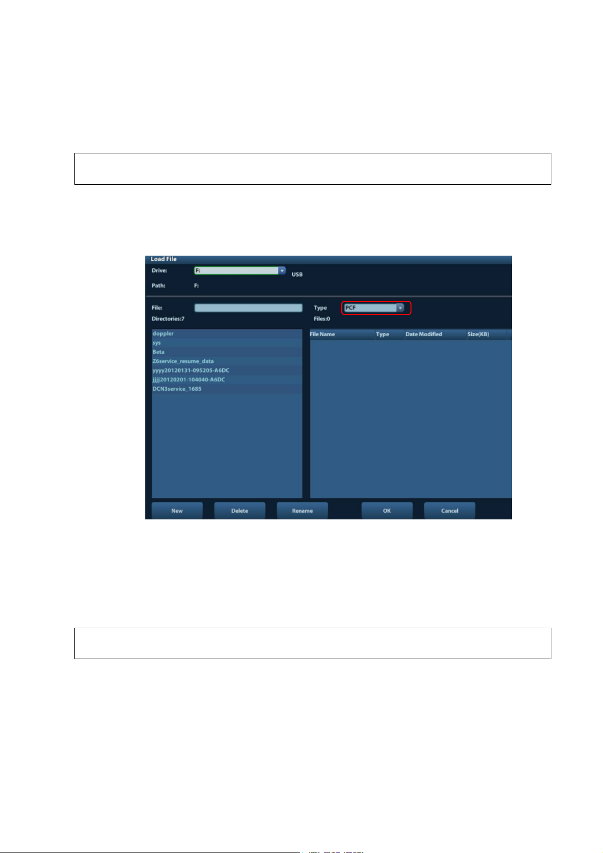
6.5 Software Maintenance
NOTE:
[Config] is available on the Maintenance menu only if the operator logged on the
system as Service.
NOTE:
After Doppler restoration, please do product configuration manually according to
the practical situation.
6.5.1 Product Configuration
1. Make the product configuration file—PCF file (generated by the production line or already
archived PCF file) according to specific requirements and copy to the USB disk.
2. Connect the USB disk to the machine, click [Config] and load the file in the popped up dialogue
box.
3. Select correct file (PCF format), and click [OK]. After the operation is completed, the successful
prompt appears. Restart the machine according to the prompt.
Specific configuration:
a) Model configuration
b) Customized product logo, hospital logo, screen saver/hibernation icon, active/inactive
icon of dual B mode, system information, boot up/shut down graphics.
6.5.2 Log Maintenance
6.5.2.1 Export the Log
1. Connect the USB disk.
2. Click [Export Log] on the Maintenance menu.
Software Upgrade and Maintenance 6-7
Page 80
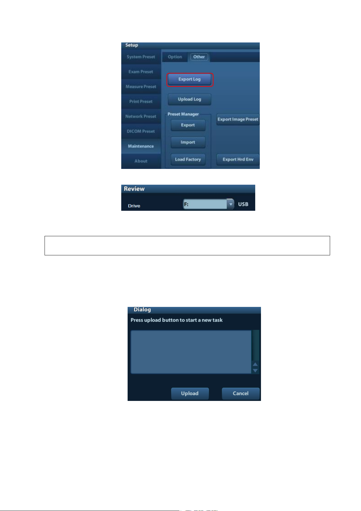
NOTE:
The log can be exported to the external USB storage device only, make sure the
connection between U disk and ultrasound is normal before the exporting.
3. Select the path in the Browse page to save the log, and click [OK].
4. When the log is exported, the system prompts “Export succeed!” click [OK] to return to the
Maintenance menu.
6.5.2.2 Log Uploading
1. Click [Upload Log] on the Maintenance menu, and select the log type in the sub-menu
2. Click [Upload] in the popping up dialogue, the system performs log uploading automatically.
After the uploading is finished, the system will prompt “Upload succeed”
If uploading is failure or can’t find the server, the system will prompt information as below.
6-8 Software Upgrade and Maintenance
Page 81
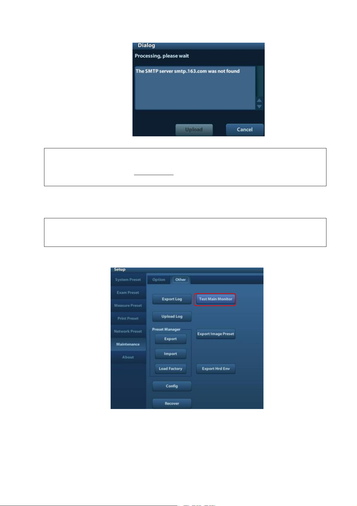
NOTE:
1.
Before uploading the log, make sure the ultrasound system has been connected
to network, otherwise, the system may warn “could not connect to server”
2.
The server (smtp.163.com) is already specified by the system, the user doesn’t
have to select it.
NOTE:
In normal condition, when changing display assembly or main board assembly, the
hardware will update the display data automatically. If synchronization fails, please
load display parameters manually to assure image effect.
6.6 Display Parameter Setting
1. Log in as Service user.
2. Enter [Maintenance] menu in Setup menu. Then select [Test Main Monitor] to enter.
3. Click the upper icon in the screen (prompts “Update” if you put the cursor on it), the update step
is carried out, if fails, please send to R&D center.
Software Upgrade and Maintenance 6-9
Page 82
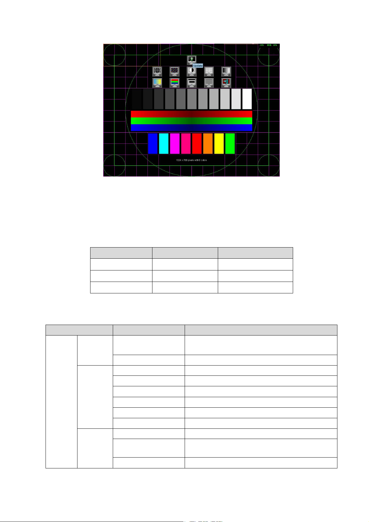
Blocks(G)
system
Notes
10
Linux
C:
≥441.7
Linux
D:
10
Linux
E:
Catalog
Data
Illustration
C:\z6
\Image
POD
Probe data (supported probes in the system)
ColorSpectrum
map data, color scale and colorize
\gui
Font
font file
Skin
Skin file
pinyinmap
pinyin data
Word
input setting data
LayoutInfo
Layout configuration file
version.txt
Version file
\app
bodymark
pictogram
DCM
structured report related data file and DICOM
viewing software
Report
report template
Figure 6-1 Main Monitor Maintenance Screen
4. After update is successful, restart the machine after power off to make the data effective.
6.7 HDD Partition
The storage capacity of the system HDD is 500G or more, and the partition information is as
follows:
1. C drive
6-10 Software Upgrade and Maintenance
Page 83
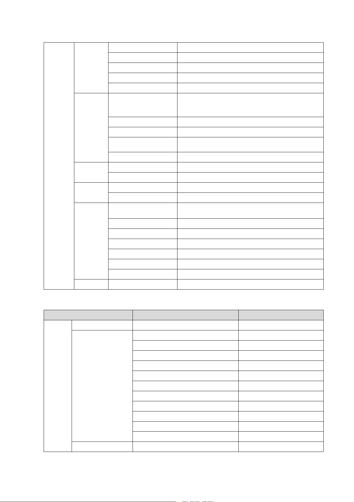
obd.bin
OBD data file
version.txt
Version file
Comment
Comment file
AnatomyImage
Anatomical images
Measurement
Measurement library
\exe
main
Doppler program and related boot configuration
file and plug-ins, remote desktop server
nls
Multilanguage string file
videoplay
Video play exe file
Sound
Cine saving and hint sound file
version.txt
Version file
\video
Picture
Display testing picture
version.txt
Version file
\preset
factory
Factory data
version.txt
Version file
\config
Boot_logo.png
Doppler boot-up graphics
Hospital logo.bmp
Hospital logo
manu_logo.png
Manufacturer logo
Real_Image.bmp
Active icon
Non_Real_Image.bmp
Inactive icon
Dorm_logo.bmp
Standby graphics
Product.PCF
Product configuration file
\Key
Factory.key
Factory key file
Catalog
Data
Illustration
D:\z6
\gui
\word
User-defined word library
\log
\DcmLog
DICOM log
\Monitor
Monitor log
\Operation
Operation log
\SystemStat
Power on/off log
\selftest
Self test log
appmon_window_monitor.txt
Appmon monitor log
message.txt
Warning message
PeriLog.txt
Peripheral log
commentlog.txt
Comment log
burn_cd_msg.txt
Burn log
error.txt
System error log
\PATIENTDATA
\
Main patient database path
2. D drive
Software Upgrade and Maintenance 6-11
Page 84

\Preset
\Current
User preset data
\temporary
\
Temporary file
\PatientBack
\
Patient back up data
Catalog
Data
Illustration
E:z6
Demo
Ivision default DEMO path
Patient Backup
Patient data back up
demofile.txt
Ivision default DEMO path
3. E drive
6-12 Software Upgrade and Maintenance
Page 85
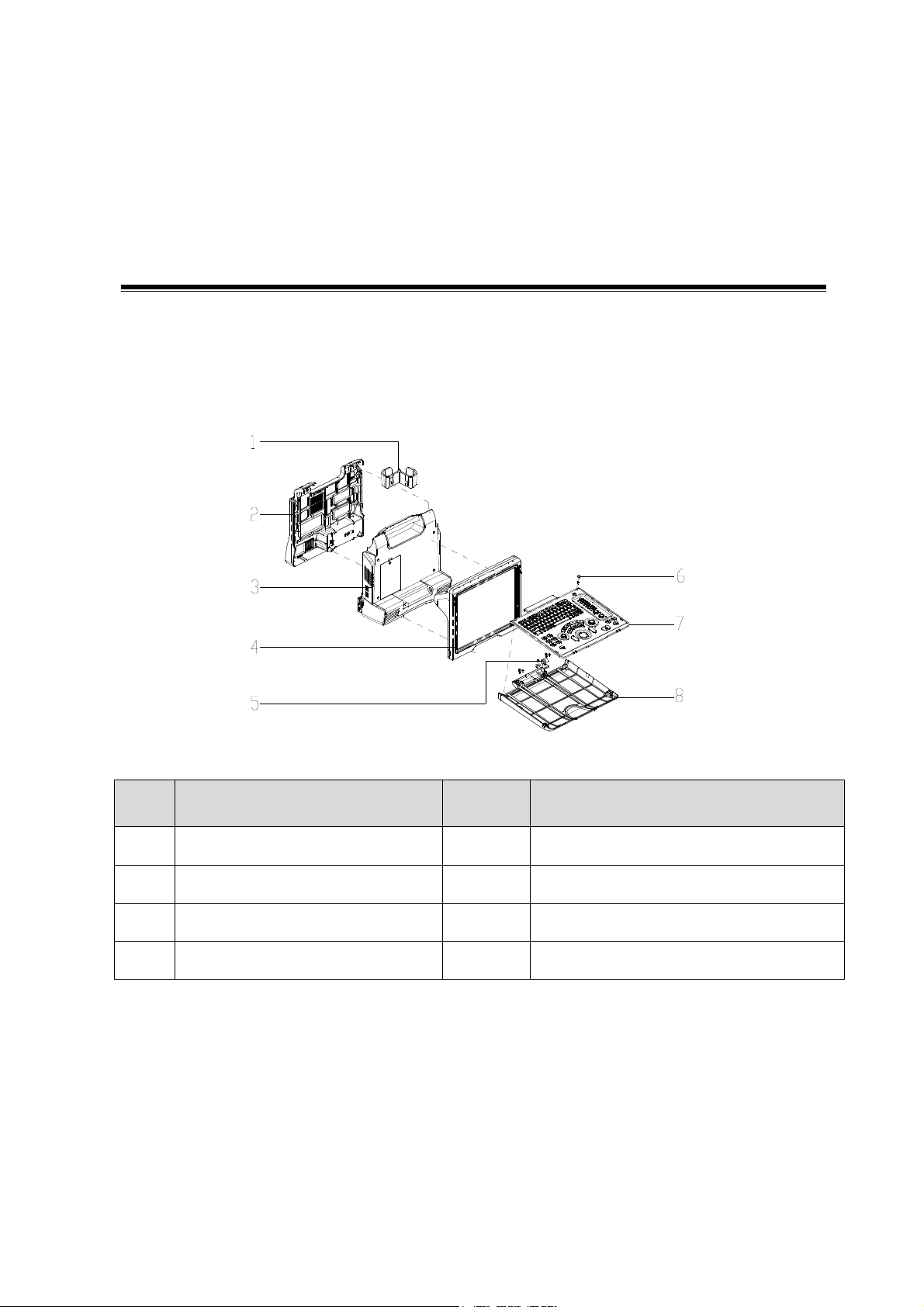
No.
Name
No.
Name
1
Holder
5
Null turning axis of keyboard
2
Rear cover assembly of main unit
6
Silicon cap of keyboard
3
Assembly of main unit rack
7
Top cover assembly of keyboard
4
Display assembly
8
Bottom cover assembly of keyboard
7 Structure and
Assembly/Disassembly
7.1 Structure of the Complete System
Figure 7-1 Overall Exploded View
Structure and Assembly/Disassembly 7-1
Page 86
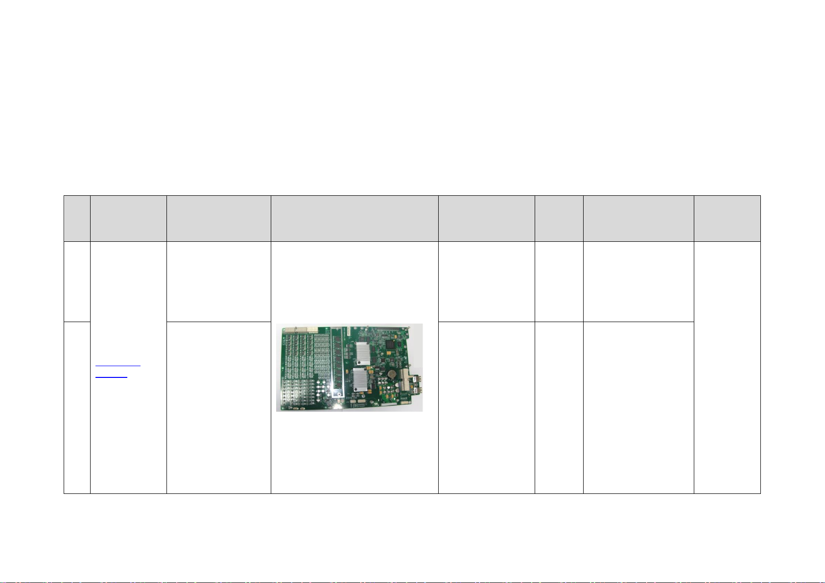
No
Classification
Description
Photo
Order Number
Model
Compatibility
Assembly/
Disassembl
y
1.
Main unit
related
Mainboard
Assembly(Z8/FRU)
115-031629-03
Z6&Z8
Series
Used for Z6/Z8 and
Z6Vet of any Doppler
software version.
Refer
to7.4.5
2.
Mainboard(FRU/No
spread spectrum
chip)
115-031629-04
Z6&Z8
Series
Used for Z6/Z8 and
Z6Vet with Doppler
software version
V02.01.00 or above.
After replacement,
restore the Doppler
software to version
V4.3.1(for human
use)/ V5.1.1(for vet
use) or above.
If the machine’s
Doppler software
version is former than
V02.01.00, use
7.2 Field Replaceable Unit
7-2 Structure and Assembly/Disassembly
Page 87
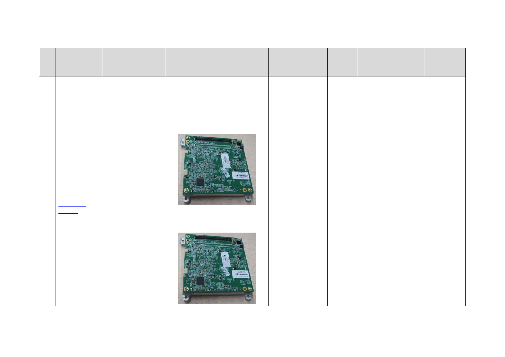
No
Classification
Description
Photo
Order Number
Model
Compatibility
Assembly/
Disassembl
y
115-031629-03.
3.
Main unit
related
BayTrail PC Module
(1112/1114 FRU)
115-043600-00
Z6&Z8
Series
BayTrail PC Module;
CPU Module with
115-043600-00 has
been discontinued. If
it is out of stock,
please use
115-043600-01 to
order and restore the
latest Doppler
software and
compatible OS as
well after
replacement.
Refer
to7.4.5
BayTrail PC Module
(1112/1114 FRU)
115-043600-01
Z6&Z8
Series
BayTrail PC Module;
CPU Module with
115-043600-00 has
been discontinued. If
it is out of stock,
please use
115-043600-01 to
order and restore the
Refer
to7.4.5
Structure and Assembly/Disassembly 7-3
Page 88
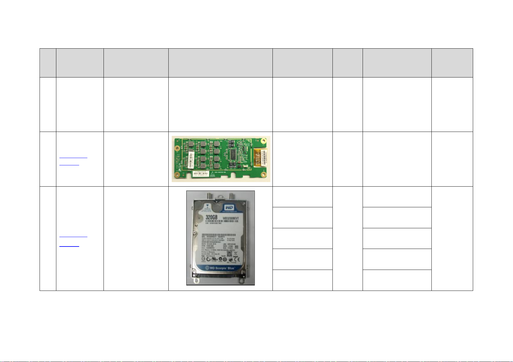
No
Classification
Description
Photo
Order Number
Model
Compatibility
Assembly/
Disassembl
y
latest Doppler
software and
compatible OS as
well after
replacement.
4.
Main unit
related
4D Module Kit
115-044346-00
Z6&Z8
Series
Z8 Platform, this
board should be used
with software of
version V04.00.00and
later.
Refer
to7.4.5
5.
Main unit
related
HDD
115-044352-00
Z6&Z8
Series
(CE)
HDD Assembly
(Z8/CE/FRU)
Refer to
7.4.8
115-044354-00
HDD Assembly
(Z8 Pro/CE/FRU)
115-044356-00
HDD Assembly
(Z8 Expert/CE/FRU)
115-044357-00
HDD Assembly
(Z8S/CE/FRU)
115-018454-03
HDD Assembly
(Z6/CE/FRU)
7-4 Structure and Assembly/Disassembly
Page 89
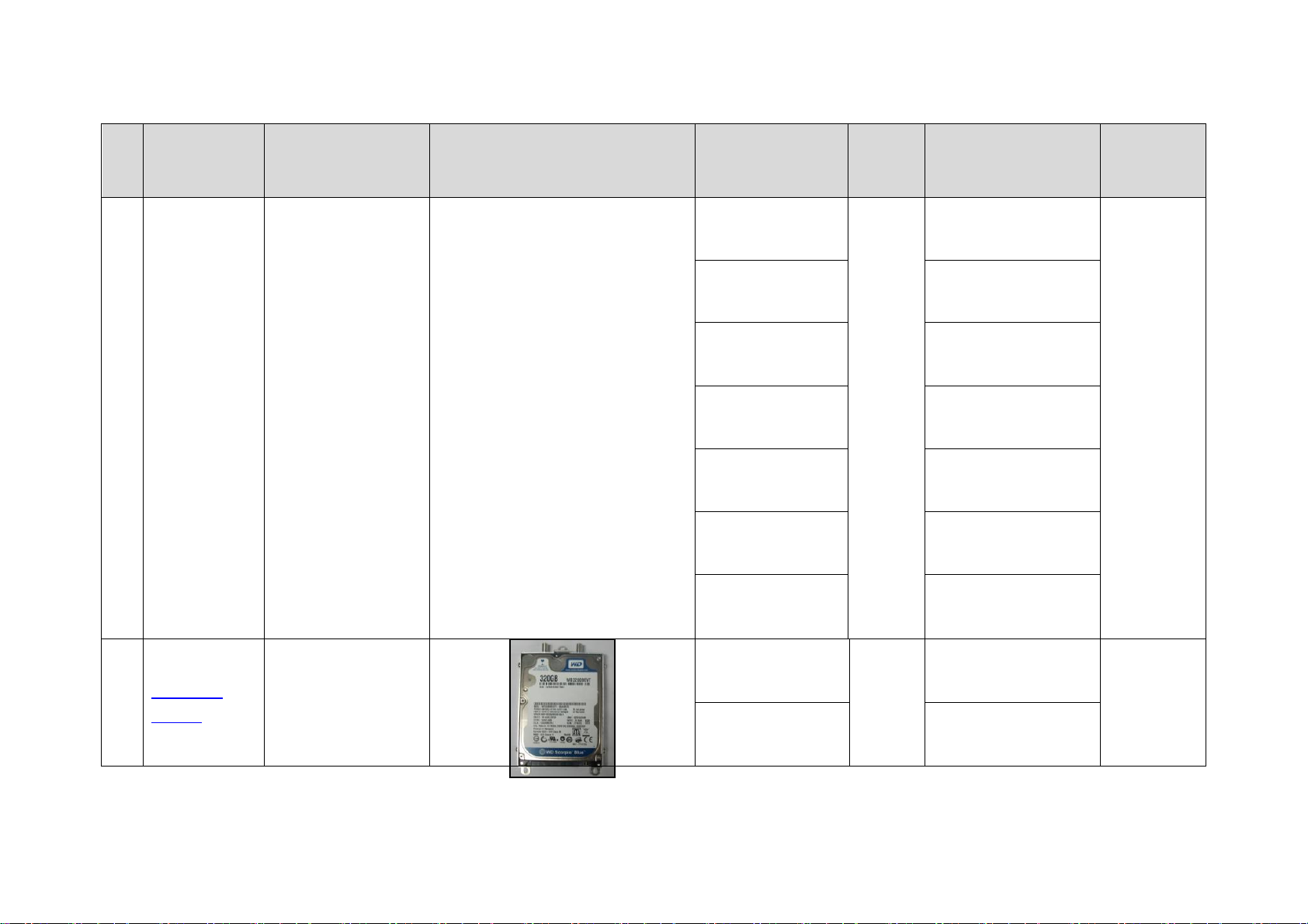
No
Classification
Description
Photo
Order Number
Model
Compatibility
Assembly/
Disassembl
y
115-044358-00
HDD Assembly
(Z6 Pro/CE/FRU)
115-044359-00
HDD Assembly
(Z6 Expert/CE/FRU)
115-044360-00
HDD Assembly
(Z6S/CE/FRU)
115-044361-00
HDD Assembly
(Z6T/CE/FRU)
115-044362-00
HDD Assembly
(Z6W/CE/FRU)
115-018455-03
HDD Assembly
(Z6Vet/CE/FRU/for
V4.0 to V5.0)
115-018455-04
HDD Assembly
(Z6Vet/CE/FRU/for
V5.0 or above)
6.
Main unit
related
HDD
115-018452-03
Z6&Z8
Series
(FDA)
HDD Assembly
(Z6/FDA/FRU/Z8
Platform)
Refer to
7.4.8
115-018453-03
HDD Assembly
(Z6Vet/FDA/FRU/for
V4.0 to V5.0)
Structure and Assembly/Disassembly 7-5
Page 90
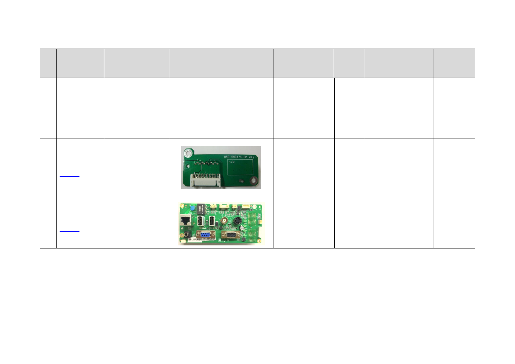
No
Classification
Description
Photo
Order Number
Model
Compatibility
Assembly/
Disassembl
y
115-018453-04
HDD Assembly
(Z6Vet/FDA/FRU/for
V5.0 or above)
7.
Main unit
related
Battery connecting
board
801-1150-00004-0
0
Z6&Z8
Series
Refer
to7.4.1
8.
Main unit
related
IO Board (Z8/FRU)
115-044349-00
Z6&Z8
Series
Z8 Platform, this
board should be used
with software of
version V04.00.00and
later.
Refer
to7.4.3
7-6 Structure and Assembly/Disassembly
Page 91
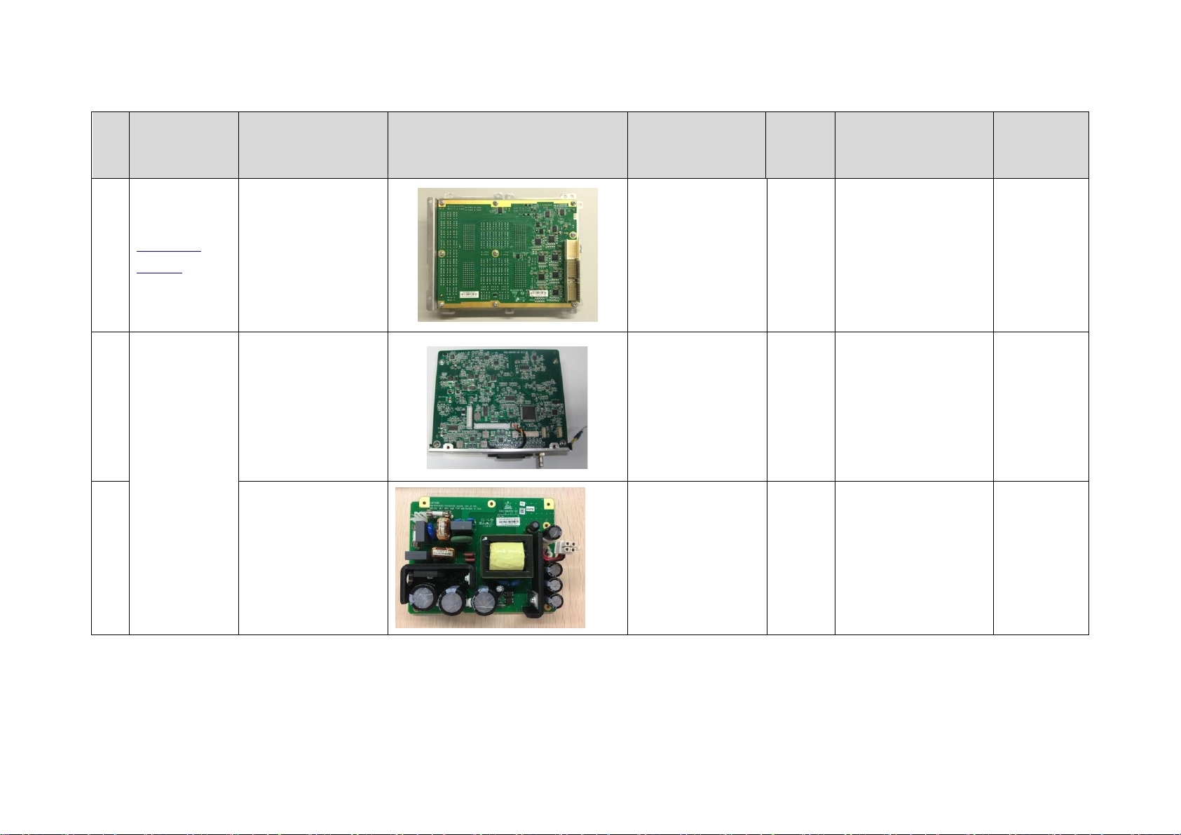
No
Classification
Description
Photo
Order Number
Model
Compatibility
Assembly/
Disassembl
y
9.
Main unit
related
Probe Board
Assembly(Z8/FRU)
115-044347-00
Z6&Z8
Series
Z8 Platform
Refer
to7.4.4
10.
Power related
power supply
module
801-1150-00009-0
0
Z6&Z8
Series
Refer to
7.4.2
11.
AC-DC board( FRU)
115-051844-00
Z6&Z8
Series
/
Refer to
7.4.2
Structure and Assembly/Disassembly 7-7
Page 92
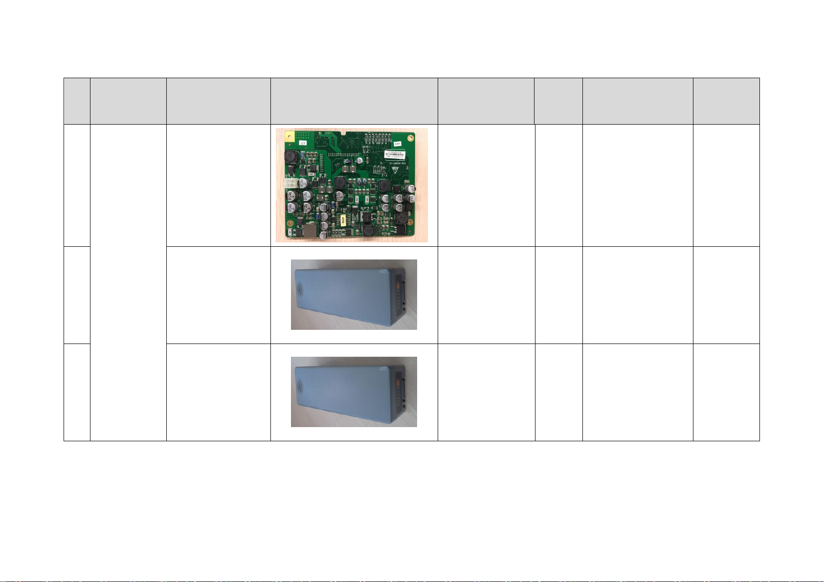
No
Classification
Description
Photo
Order Number
Model
Compatibility
Assembly/
Disassembl
y
12.
DC-DC board( FRU)
115-051845-00
Z6&Z8
Series
/
Refer to
7.4.2
13.
Battery (CE)
115-011471-00
Z6&Z8
Series
(CE)
For CE
Refer
to7.4.1
14.
Battery(FDA)
115-011472-00
Z6&Z8
Series
(FDA)
For FDA
Refer
to7.4.1
7-8 Structure and Assembly/Disassembly
Page 93
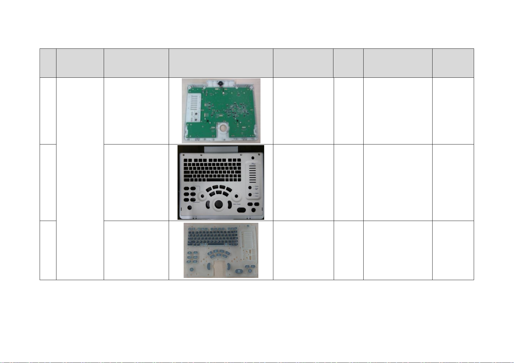
No
Classification
Description
Photo
Order Number
Model
Compatibility
Assembly/
Disassembl
y
15.
Top Cover of
Keyboard
Assembly(Z8/FRU)
115-044348-00
Z6&Z8
Series
Z8 Platform, this
board should be used
with software of
version V04.00.00and
later.
Refer
to7.4.6.5
16.
Control Panel
Cover(Z8/FRU)
115-044386-00
Z6&Z8
Series
Z8 Platform
Refer
to7.4.6.5
17.
Silicon
Keypad(Z8/FRU)
115-044387-00
Z6&Z8
Series
Z8 Platform
Structure and Assembly/Disassembly 7-9
Page 94
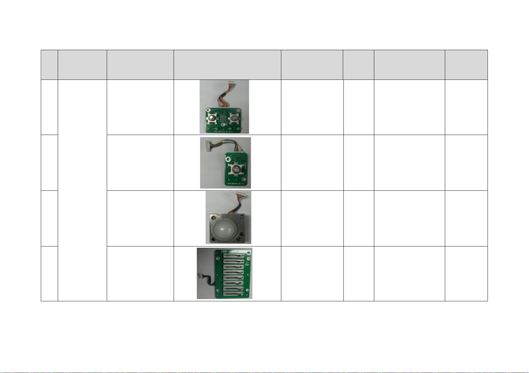
No
Classification
Description
Photo
Order Number
Model
Compatibility
Assembly/
Disassembl
y
18.
Double encoder
801-1150-00013-0
0
Z6&Z8
Series
Refer to “Focus/Freq
and Depth/Zoom”
Refer
to7.4.6.1
19.
Single encoder
801-1150-00014-0
0
Z6&Z8
Series
Refer to “Gain” or
"Nav.Rot"
Refer
to7.4.6.1
20.
Trackball
801-1150-00015-0
0
Z6&Z8
Series
Refer
to7.4.6.2
21.
TGC board
801-1150-00016-0
0
Z6&Z8
Series
Refer
to7.4.6.3
7-10 Structure and Assembly/Disassembly
Page 95
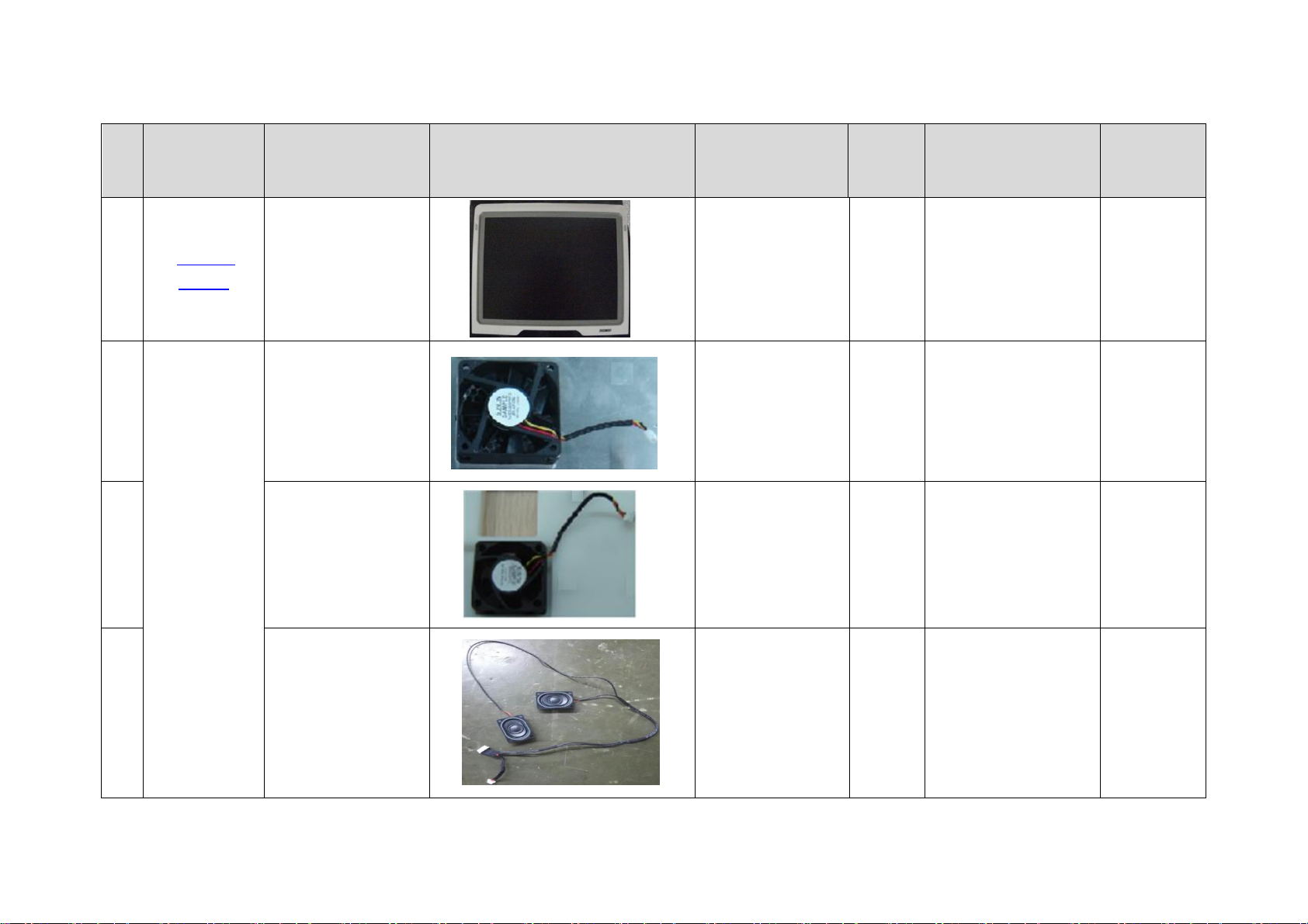
No
Classification
Description
Photo
Order Number
Model
Compatibility
Assembly/
Disassembl
y
22.
Monitor
related
1150 Display
assembly
115-045050-00
Z6&Z8
Series
Refer
to7.4.7
23.
Others
Backboard fan
024-000147-00
Z6&Z8
Series
Refer
to7.4.5
24.
Power fan
024-000146-00
Z6&Z8
Series
Refer
to7.4.2.1
25.
Speaker
115-045172-00
Z6&Z8
Series
Refer
to7.4.9
Structure and Assembly/Disassembly 7-11
Page 96
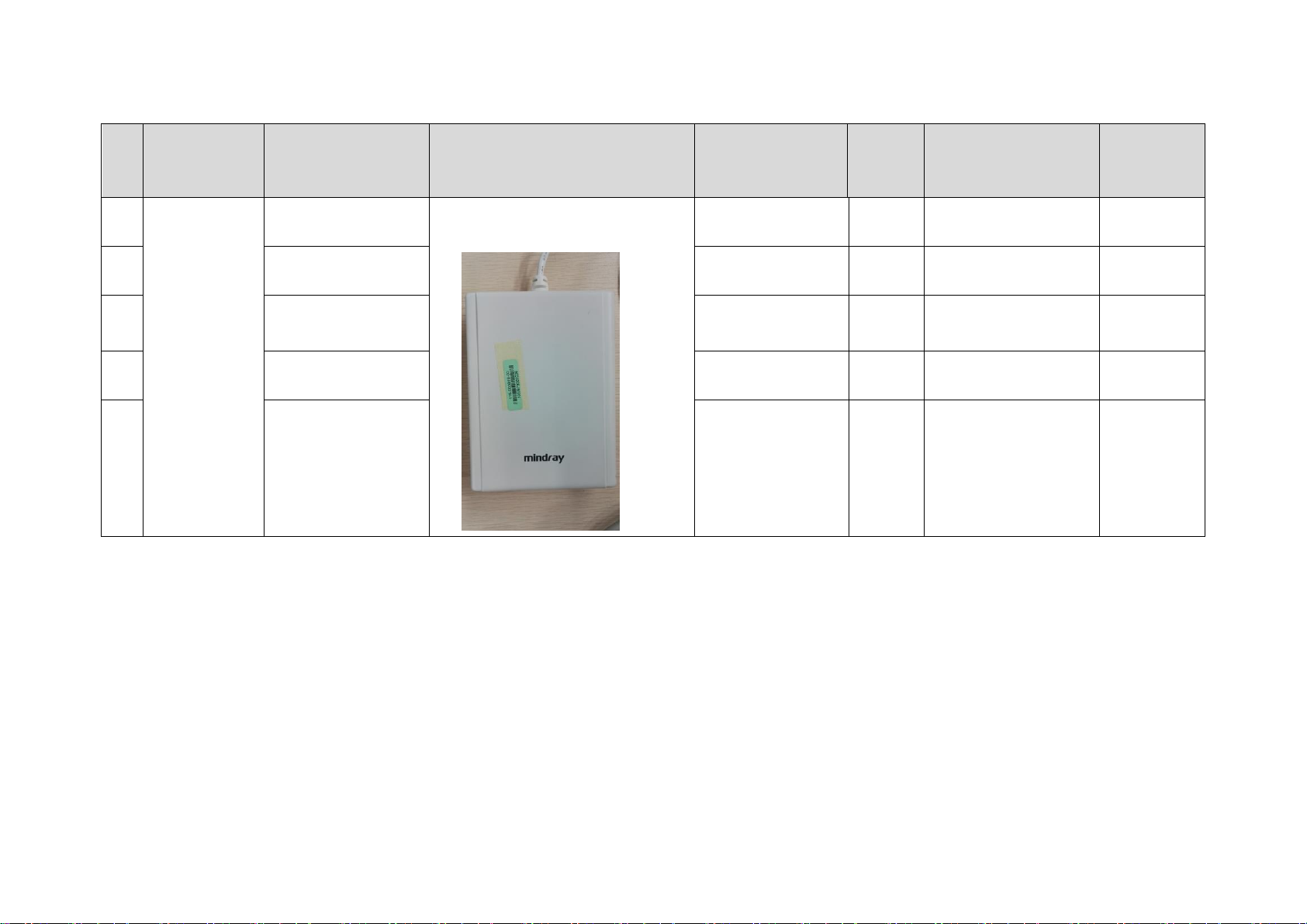
No
Classification
Description
Photo
Order Number
Model
Compatibility
Assembly/
Disassembl
y
26.
ECG Module (AHA
lead/CE/Z6Vet)
115-050430-00
Only for maintenance
27.
ECG Module (IEC
lead/CE/Z6Vet)
115-050431-00
Only for maintenance
28.
ECG Module (AHA
lead/FDA/Z6Vet)
115-050517-00
Only for maintenance
29.
ECG Module (AHA
lead/CE)
115-044646-00
Only for maintenance
30.
ECG Module (IEC
lead/CE)
115-044647-00
Only for maintenance
7-12 Structure and Assembly/Disassembly
Page 97
WARNING:
Please start to disassemble when you are sure that you have pull
battery out.
7.3 Preparations
7.3.1 Tools Required
Cross-headed screwdriver: 1pcs, Spec: 105 X100
Anti-static gloves: 1 pair
7.3.2 Engineers Required
Only technical professionals from Mindray or engineers authorized by Mindray after training
can perform maintenance and check.
7.3.3 Assembly/Disassembly Required
You should perform the following preparations before the disassembling of ultrasound equipment.
1. When you stop the scanning and the image capture, you should power off the system and
disconnect the system from the AC power supply, then pull out AC power cables.
2. Open the battery cover and removing battery.
3. Prepare Tools disassembled and anti-static gloves.
7.4 Assembly/Disassembly
This section describes the disassembling and assembling of the main modules and boards. The
assembling is the inverse process of disassembling if not mentioned in particular.
Sketch map
Structure and Assembly/Disassembly 7-13
Page 98
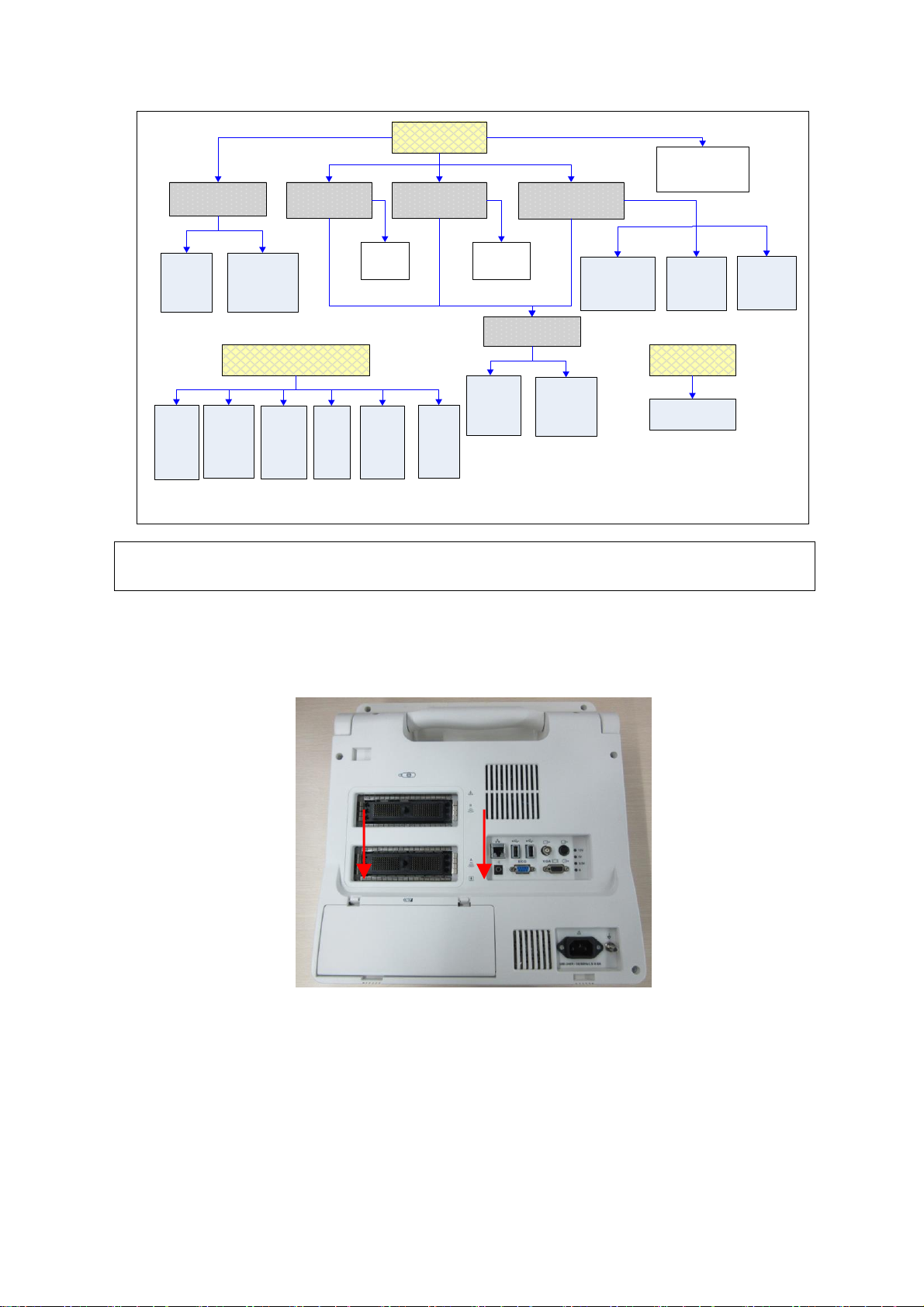
Main unit
rear cover
IO
assembly
Probe
board
assembly
IO
boar
d
Probe
board
Top cover
assembly
of keyboard
Track
ball
Encod
er
Control
panel
Display
assembly
Power
module
AC-DC
power
board
Power
tailboard
assembl
y
DC-DC
power
board
TGC
assembl
y
Silica
gel key
board
Buzze
r
Backligh
t
inverter
board
LCD
scree
n
Main unit
front cover
HDD
Main board
assembly
CPU
module
Main
board
Note:
1. The up-to-down arrows indicate the
assembly/disassembly sequence
2. The box with the same content format
indicates independent assembly
Battery
connecting
board
7.4.1 Battery Connecting Board
NOTE:
The illustration of disassemble is provided for reference only, and the concrete
picture depends on the actual model.
1. Press the clasp of the battery cover, and then rotate the battery cover down to open it.
Figure 7-2 Disassembly of Battery (1)
2. Slide battery to the left side pressing it all the time, and then remove the battery when the
battery pops on the recommended distance.
7-14 Structure and Assembly/Disassembly
Page 99
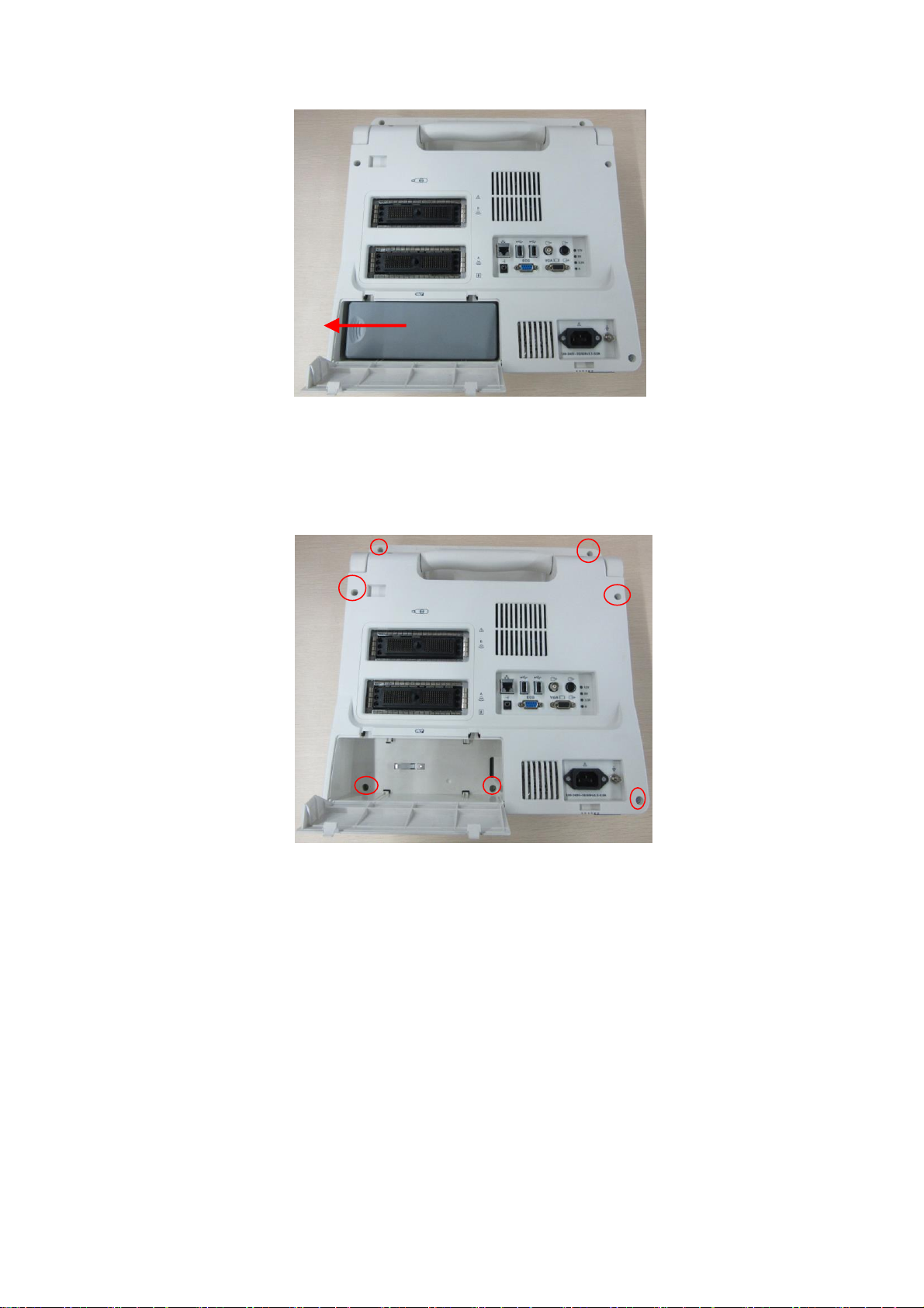
Figure 7-3 Disassembly of Battery (2)
3. Remove panhead screws with washers (5 M3X8 and 2 M3X12) which are installed on the
rack of the main unit rear cover.
Figure 7-4 Disassembly of Rear Cover Assembly of Main Unit (1)
4. Hold the battery bay and then remove the rear cover of the main unit simultaneously, pull out
the plugs from the battery connecting board.
Structure and Assembly/Disassembly 7-15
Page 100
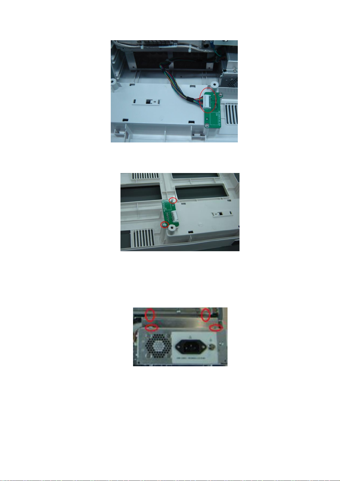
Figure 7-5 Disassembly of Rear Cover Assembly of Main Unit (2)
5. Remove panhead screws with washers (2 M3X6) fixed on the main unit box, and then take off
the battery connecting board.
Figure 7-6 Removing the Battery Connecting Board
7.4.2 Power Supply Module
1. Remove rear cover assembly of the main unit (referring to 7.4.1 the 1~4 step)
2. Remove panhead screws with washers (4 M3X6) fixed on the main unit box.
Figure 7-7 Removing the power shielding box
3. Then take off the power shielding box. Pull out the plug of the battery connecting board
cables on the power module assembly.
4. After removing panhead screws with washers (6 M3X6) fixed on the main unit box and one
panhead combination screw (M4X8), and pulling out the plug of the cables connecting the
power module and main board, you can take out the power board assembly backward.
7-16 Structure and Assembly/Disassembly
 Loading...