

Page 1

BeneVision
TM80 Telemetry Monitor
Service Manual
Page 2

Page 3

Intellectual Property Statement
SHENZHEN MINDRAY BIO-MEDICAL ELECTRONICS CO., LTD. (hereinafter called
Mindray) owns the intellectual property rights to this product and this manual. This
manual may refer to information protected by copyrights or patents and does not
convey any license under the patent rights of Mindray, nor the rights of others.
Mindray does not assume any liability arising out of any infringements of patents or
other rights of third parties.
Mindray intends to maintain the contents of this manual as confidential information.
Disclosure of the information in this manual in any manner whatsoever without the
written permission of Mindray is strictly forbidden.
Release, amendment, reproduction, distribution, rent, adaptation and translation of
this manual in any manner whatsoever without the written permission of Mindray is
strictly forbidden.
, and are the registered trademarks or
trademarks owned by Mindray in China and other countries. All other trademarks
that appear in this manual are used only for editorial purposes without the intention
of improperly using them. They are the property of their respective owners.
This posting serves as notice under 35 U.S.C.§287(a) for Mindray patents:
http://www.mindrayna.com/patents.
For this manual, the issued Date is June, 2020 (Version: 4.0).
© 2017-2020 Shenzhen Mindray Bio-Medical Electronics Co., Ltd. All rights reserved
BeneVision TM80 Telemetry Monitor Service Manual I
Page 4

NOTE
This manual describes all features and options. The equipment may not have
all of them. Contact Mindray service department for any questions.
Manufacturer’s Responsibility
Contents of this manual are subject to changes without prior notice.
All information contained in this manual is believed to be correct. Mindray shall not
be liable for errors contained herein nor for incidental or consequential damages in
connection with the furnishing, performance, or use of this manual.
Mindray is responsible for the effects on safety, reliability and performance of this
product, only if:
All installation operations, expansions, changes, modifications and repairs of this
product are conducted by Mindray authorized personnel;
The electrical installation of the relevant room complies with the applicable
national and local requirements;
The product is used in accordance with the instructions for use.
WARNING
This manual is for biomedical engineers or technicians responsible for
troubleshooting, repairing, and maintaining the telemetry monitoring
system.
II BeneVision TM80 Telemetry Monitor Service Manual
Page 5

Return Policy
In the event that it becomes necessary to return a unit to Mindray, follow the
instructions below.
1. Obtain a return authorization.
Contact the Mindray Service Department and obtain a Mindray Customer Service
Authorization Number. The Mindray Customer Service Authorization Number must
appear on the outside of the shipping container. Return shipments will not be
accepted if the Mindray Customer Service Authorization Number is not clearly
visible. Please provide the model number, serial number, and a brief description of
the reason for return.
2. Freight policy
The customer is responsible for freight charges when this product is shipped to
Mindray for service (including any relevant customs fees or other freight related
charges).
3. Return address
Please send the part(s) or equipment to the address offered by Customer Service
Department.
BeneVision TM80 Telemetry Monitor Service Manual III
Page 6

Contact Information
Manufacturer: Shenzhen Mindray Bio-Medical Electronics Co., Ltd.
Address: Mindray Building, Keji 12th Road South, High-tech Industrial
park, Nanshan, Shenzhen 518057,P.R.China
Website: www.mindray.com
E-mail Address: [email protected]
Tel : +86 755 81888998
Fax: +86 755 26582680
Distributor: Mindray DS USA, Inc.
Address: 800 MacArthur Boulevard, Mahwah, New Jersey 07430, USA
Tel : 1.800.288.2121, 1.201.995.8000
Website: www.mindray.com
IV BeneVision TM80 Telemetry Monitor Service Manual
Page 7

Preface
Manual Purpose
This manual provides detailed information about the assembling, dissembling,
testing and troubleshooting of the equipment to support effective troubleshooting
and repair. It is not intended to be a comprehensive, in-depth explanation of the
product architecture or technical implementation. Observance of the manual is a
prerequisite for proper equipment maintenance and prevents equipment damage
and personnel injury.
This manual is based on the maximum configuration. Therefore, some contents may
not apply to your device. If you have any question, please contact our Customer
Service Department.
Intended Audience
This manual is for biomedical engineers, authorized technicians or service
representatives responsible for troubleshooting, repairing and maintaining the
TM80 Telemetry Monitors.
BeneVision TM80 Telemetry Monitor Service Manual V
Page 8

FOR YOUR NOTES
VI BeneVision TM80 Telemetry Monitor Service Manual
Page 9

Table of Contents
1 Safety ........................................................................................................................ 1-1
1.1 Safety Information ................................................................................................................... 1-1
1.1.1 WARNINGS ..................................................................................................................... 1-2
1.1.2 Cautions ......................................................................................................................... 1-3
1.1.3 Notes ............................................................................................................................... 1-4
1.2 Equipment Symbols .............................................................................................. 1-4
2 Overview ................................................................................................................... 2-1
2.1 Product Overview .................................................................................................................... 2-1
2.2 Key Features ............................................................................................................................... 2-2
2.3 Introduction to TM80 Telemetry Monitoring System ................................................. 2-2
2.3.1 Module Configurations for the TM80 Telemetry Monitor ............................ 2-3
2.3.2 Connection Diagram of the TM80 Telemetry Monitor .................................. 2-3
2.4 Architecture of the TM80 Telemetry Monitoring System .......................................... 2-5
3 Installation ................................................................................................................ 3-1
3.1 Overview ..................................................................................................................................... 3-1
3.1.1 Introduction .................................................................................................................. 3-1
3.1.2 Business Types ............................................................................................................. 3-2
3.1.3 Installation Process ..................................................................................................... 3-4
3.2 Network Requirements of the TM80 ................................................................................. 3-9
3.2.1 Requirements for Network Feasibility ............................................................... 3-10
3.2.2 Configuration Requirements for WLAN of TM80 ........................................... 3-19
3.3 Configuration of Cisco Network Devices ....................................................................... 3-22
3.3.1 Recommended Devices .......................................................................................... 3-22
3.3.2 Configuration Description ..................................................................................... 3-23
3.3.3 WLAN Settings ........................................................................................................... 3-24
BeneVision TM80 Telemetry Monitor Service Manual 1
Page 10

3.3.4 CONTROLLER Settings ............................................................................................. 3-29
3.3.5 WIRELESS Settings .................................................................................................... 3-31
3.4 Configuration of Aruba Network Devices ..................................................................... 3-36
3.4.1 Recommended Devices .......................................................................................... 3-37
3.4.2 Login .............................................................................................................................. 3-37
3.4.3 Wireless Setting ......................................................................................................... 3-39
3.4.4 Network Setting ........................................................................................................ 3-45
3.5 Configuration of Netgear Network Devices ................................................................. 3-46
3.5.1 Preparation .................................................................................................................. 3-47
3.5.2 Setting Single AP ....................................................................................................... 3-48
3.5.3 Wireless Settings (5G) .............................................................................................. 3-54
3.5.4 Setting Multiple APs ................................................................................................ 3-57
3.6 Network Deployment Planning ........................................................................................ 3-60
3.6.1 Tools and Resources ................................................................................................. 3-60
3.6.2 Environmental Survey ............................................................................................. 3-60
3.7 Network Deployment Implementation ......................................................................... 3-65
3.7.1 Preparations before Equipment Installation ................................................... 3-65
3.7.2 Roaming Consideration .......................................................................................... 3-66
3.7.3 Services Provided During and After Installation ........................................... 3-66
3.8 Network Verification ............................................................................................................. 3-67
3.8.1 Tools and Resources ................................................................................................. 3-67
3.8.2 Wi-Fi Signal Calibration ........................................................................................... 3-67
3.8.3 Confirm Network Feasibility ................................................................................. 3-68
3.8.4 Network Verification Process ................................................................................ 3-69
3.9 Configuring WLAN Settings of TM80 .............................................................................. 3-70
3.9.1 WLAN Setup ................................................................................................................ 3-71
3.9.2 EAP Setup .................................................................................................................... 3-72
3.9.3 EAP Certificate Management ............................................................................... 3-73
3.9.4 WLAN TEST .................................................................................................................. 3-81
3.9.5 5G Band Channels .................................................................................................... 3-84
3.10 Network Verification with TM80 ..................................................................................... 3-84
2 BeneVision TM80 Telemetry Monitor Service Manual
Page 11

3.10.1 Test Preparation ...................................................................................................... 3-84
3.10.2 Connecting a TM80 to the Central Station .................................................... 3-85
3.10.3 Test Preparation ...................................................................................................... 3-86
3.10.4 Coverage Confirmation ........................................................................................ 3-86
3.10.5 TM80Acceptance Confirmation ........................................................................ 3-88
3.11 Appendices ............................................................................................................................ 3-89
3.11.1 TM80 Wi-Fi Network Requirement Table ........................................................ 3-89
3.11.2 Environmental Survey Table ............................................................................... 3-93
3.11.3 Network Acceptance Table ................................................................................. 3-98
3.11.4 TM80 Verification Confirmation Table .......................................................... 3-104
4 Product Principles .................................................................................................... 4-1
4.1 System Composition ............................................................................................................... 4-1
4.2 System Signal Flow .................................................................................................................. 4-4
5 Testing and Maintenance ......................................................................................... 5-1
5.1 Recommended Maintenance and Test Frequency ...................................................... 5-2
5.2 Inspection before Daily Use ................................................................................................. 5-2
5.3 Preventative Maintenance Procedures ............................................................................ 5-3
5.4 Parameter Test ........................................................................................................................... 5-3
5.4.1 ECG Test .......................................................................................................................... 5-3
5.4.2 Resp Test ......................................................................................................................... 5-4
5.4.3 SpO2Tes t ......................................................................................................................... 5-5
5.4.4 NIBP Tests ....................................................................................................................... 5-7
5.5 Miscellaneous Tests ............................................................................................................... 5-10
5.5.1 Visual Inspection ....................................................................................................... 5-10
5.5.2 Power-On Test ............................................................................................................ 5-11
5.5.3 Nurse Call Test ............................................................................................................ 5-11
5.5.4 Electric Safety Test .................................................................................................... 5-11
5.5.5 Network Print Test ..................................................................................................... 5-12
5.5.6 Battery Check ............................................................................................................. 5-12
BeneVision TM80 Telemetry Monitor Service Manual 3
Page 12

6 Hardware Upgrade ................................................................................................... 6-1
6.1 Adding the SpO2 Function .................................................................................................... 6-1
6.2 Adding the NIBP Module (BP10) ......................................................................................... 6-1
7 Troubleshooting ....................................................................................................... 7-1
7.1 Common Faults ......................................................................................................................... 7-1
7.1.1 The TM80 Failed to Connect to the Central Station ........................................ 7-1
7.1.2 The TM80 Are Offline Frequently ........................................................................... 7-2
7.1.3 The TM80 Cannot Be Powered On ........................................................................ 7-2
7.1.4 The Working Duration of Battery Becomes Short ........................................... 7-3
7.2 Technical Alarms ....................................................................................................................... 7-3
7.3 Other Faults .............................................................................................................................. 7-12
7.4 Error Codes ............................................................................................................................... 7-17
7.4.1 Common Error Codes .............................................................................................. 7-17
7.4.2 Software Update Failure Error Codes ................................................................. 7-19
A Electrical Safety Inspection .................................................................................... A-1
A.1 Electrical Safety Tests for the TM80, BP10, and Central charger ............................ A-1
A.2 Power Cord Plug ...................................................................................................................... A-2
A.3 Device Enclosure and Accessories .................................................................................... A-3
A.4 Device Labeling ....................................................................................................................... A-4
A.5 Earth Leakage Test .................................................................................................................. A-4
A.6 Patient Leakage Current ....................................................................................................... A-6
A.7 Mains on Applied Part Leakage ......................................................................................... A-9
A.8 Patient Auxiliary Current ................................................................................................... A-12
A.9 Scheduled Electrical Safety Inspection ........................................................................ A-13
A.10 Electrical Safety Inspection after Repair ................................................................... A-14
A.11 Electrical Safety Inspection Form ................................................................................ A-15
4 BeneVision TM80 Telemetry Monitor Service Manual
Page 13

1 Safety
1.1 Safety Information
WARNING
Indicates a potential hazard or unsafe practice that, if not avoided, could
result in death or serious injury.
CAUTION
Indicates a potential hazard or unsafe practice that, if not avoided, could
result in minor personal injury or product/property damage.
NOTE
Provides application tips or other useful information.
BeneVision TM80 Telemetry Monitor Service Manual 1-1
Page 14

1.1.1 WARNINGS
WARNING
The TM80 Telemetry Monitor must be operated by medical personnel
inhospitals or medical institutions.
For continued safe use of the TM80 Telemetry Monitor, the
instructionsgiven in this manual must be followed. But instructions in this
manual inno way supersede established medical procedures.
To avoid explosionhazard, do not use the TM80 Telemetry Monitor in the
presence of oxygen-rich atmospheres, flammable anesthetics, or other
flammableagents.
The TM80 Telemetry Monitor is not to be used in the vicinity of
electrosurgicalunits because such use may interrupt or interfere with
thetransmission of signals from the TM80 Telemetry Monitor.
Do not use the TM80 Telemetry Monitor in conjunction with Electro
SurgicalUnit (ESU).
Do not expose the TM80 Telemetry Monitor to a Magnetic Resonance
(MR) environment.
We recommend that the latest WPA2-PSK security encryption mode
beused when the TM80 Telemetry Monitor is in use.
Auditory alarm signal sound pressure levels that are less than
ambientlevels can impede operator recognition of alarm conditions.
1-2 BeneVision TM80 Telemetry Monitor Service Manual
Page 15

1.1.2 Cautions
CAUTION
Do not let the display of the TM80 Telemetry Monitor directly touch
thepatient’s skin when the display is on.
When the Central Station presents the alarm”Offline”, check thenetwork
connection status.
When disposing of the packaging material, be sure to observe the
applicablelocal waste control regulations and keep it out of children’s
reach.
Mindray takes no responsibility for controlling the radio frequency
environmentin a hospital. If interference for the operating frequency
oftelemetry equipment exists, the telemetry equipment performance
willbe affected. Exercise caution when selecting the operating frequency
ofall the wireless equipment in a hospital as this is very important to
avoidmutual interference among them.
Magnetic and electrical fields are capable of interfering with the
properperformance of the TM80 Telemetry Monitor. For this reason make
surethat all external equipment operated in the vicinity of the TM80
TelemetryMonitor comply with the relevant EMC requirements. Mobile
phone,X-ray equipment, micro-wave oven, interphone, or MRI equipment
are apossible source of interference as they may emit higher levels of
electromagneticradiation.
BeneVision TM80 Telemetry Monitor Service Manual 1-3
Page 16

1.1.3 Notes
NOTE
Put the TM80 Telemetry Monitor in a location where you can easily seethe
screen and access the operating controls
The software of the TM80 Telemetry Monitor was developed in
compliancewith IEC60601-1-4. The possibility of hazards arising from
softwareerrors is minimized.
This manual describes all features and options. Your equipment may
nothave all of them.
Keep this manual in the vicinity of the equipment so that it can be
obtained conveniently when needed.Provides application tips or other
useful information.
1.2 Equipment Symbols
See BeneVision TM80 Telemetry Monitor Operator’s Manual for information about
the symbols used on this product and its packaging.
1-4 BeneVision TM80 Telemetry Monitor Service Manual
Page 17

2 Overview
2.1 Product Overview
The TM80 telemetry monitor is intended for use on Adult and Pediatric patients over
three years old to monitor ECG, SpO2, NIBP and Resp physiological data. The
physiological data can be analyzed, alarmed, stored, reviewed locally on the display
of the monitor, and the CentralStation can config and display the physiological
parameters from the TM70. The TM70 telemetry monitor is intended for use in
professional healthcare facilities under the direct supervision of a licensed
healthcare practitioner.
The TM80 telemetry monitor can only be admitted by the Central Monitoring
System (CMS) whose version is 03.00 or above.
WARNING
The TM80 Telemetry Monitormust be operated by medical personnel
inhospitals or medical institutions.
The TM80 Telemetry Monitor is not designed for monitoring critically
illpatients.
As the TM80 Telemetry Monitortransmits data wirelessly, there mightbe a
risk of data loss.
The TM80 Telemetry Monitorcan be powered by a rechargeable lithium-ion
battery (P/N 022-000196-00 )or three AA batteries (P/N 0000-10-10902).
Misuse or improper maintenance of the rechareable lithium-ion batterycan
cause a battery to overheat during use.
High temperatures can cause burns to the TM80. Refer to BeneVision TM80
BeneVision TM80 Telemetry Monitor Service Manual 2-1
Page 18

Telemetry Monitor Operator’s Manual for the maintenance methods.
WARNING
Before maintaining and repairing the TM80 Telemetry Monitor, familiarize
yourself with the BeneVision TM80 Telemetry Monitor Operator’s Manual.
2.2 Key Features
Easy for clinicians to use and comfortable for patients to wear
Low power consumption
Supports IEEE 802.11a/b/g/n/ac and 2.4GHz/5Ghz dual Wi-Fi band
Able to be accessed to the existing wireless networks in a hospital directly
2.3 Introduction to TM80 Telemetry Monitoring System
The TM80 Telemetry Monitor consists of a transmission system, a receiving system,
and a central monitoring system (abbreviated as CMS).
The transmission system refers to the TM80 Telemetry Monitor with
optional BP10 and SAT10 SpO
the SpO
sensor connector and then plugged into the SpO2connector on
2
modules. The SpO2module is connected to
2
the TM80.The BP10 is a standalone module and communicates with the
TM80 via Mindray Patient Area Network (abbreviated as MPAN).
The receiving system refers to the Wi-Fi network, including APs, switches,
and routers. The TM80 can use the dedicated Wi-Fi network provided by
Mindray or share the hospital’s network with other devices in the hospital.
The network must comply with the wireless specifications of Mindray. For
details of specifications, refer to 3Installation.
2-2 BeneVision TM80 Telemetry Monitor Service Manual
Page 19
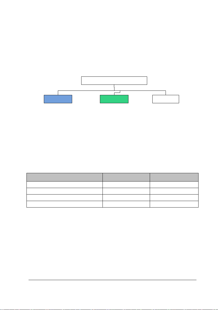
Telemetry Monitoring system
Transmission
system
AP array CMS
Receive data
Data analysis
Data management
Information display
Collect and upload ECG/SpO2/
NIBP/RESP parameters
Local alarm
Local storage and review
Upload data
ECG
Yes / Resp
Yes / SpO2
/
Yes
NIBP / Yes
The CMS refers to BeneVision Central Monitoring System. For details about
the Benevision Central Monitoring System, refer to BeneVision Central
Monitoring System Operator’s Manual (P/N H-046-010879-00).
The following figure shows relationships among the subsystems.
2.3.1 Module Configurations for the TM80 Telemetry Monitor
The table below shows the ECG, Resp, SpO2, and NIBP configuration status for the
TM80 Telemetry Monitor.
Parameter Standard Optional
2.3.2 Connection Diagram of the TM80 Telemetry Monitor
The following figures illustrates how the ECG, SpO2, and NIBP modules are
connected to the TM80 Telemetry Monitor.
BeneVision TM80 Telemetry Monitor Service Manual 2-3
Page 20

ECG/RESP
collection
TM80
Telemetry
Monitor
SpO2 module
NIBP
measurement
Wired connection
Wireless
connection
The ECG and Resp collection circuit is designed inside the TM80 Telemetry Monitor.
The SpO
to the TM80 Telemetry Monitor via the SpO
module and sensor constitute a SpO2 cable. The SpO2 module is connected
2
cable.
2
Hard connection is used between the cable and the monitor. The NIBP module is a
standalone module and performs short-range wireless communication with TM80
Telemetry Monitor.
2-4 BeneVision TM80 Telemetry Monitor Service Manual
Page 21
AP
AP
...
100
/1000
Mbps Switch
WLAN
802
.
11
a
/b
/g
/
n/ac
...
Network
AP
AP
...
100/
1000Mbps Switch
WLAN
802
.
11a
/
b
/
g
/
n/ac
...
...
CMS
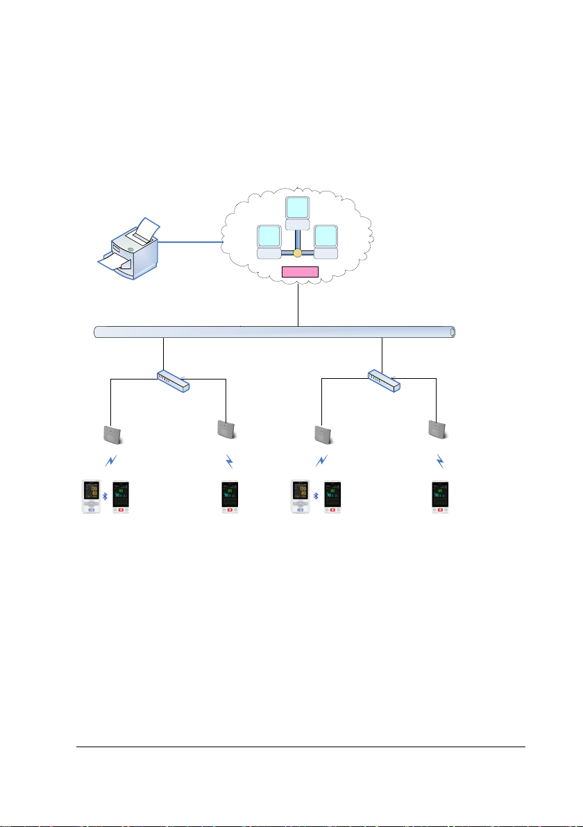
2.4 Architecture of the TM80 Telemetry Monitoring System
The following figure illustrates the physical units of the TM80 Telemetry Monitoring
System. It shows how these devices and functional units are interconnected to form
a complete telemetry monitoring system.
The TM80 Telemetry Monitors are worn on patients. As shown in the figure above,
patients’ physiological information collected by the TM80 Telemetry Monitors is
transmitted through the low power consumption Wi-Fi modules built in the
telemetry monitors. Wireless signals are acquired by AP arrays and then are
transmitted to the CMS through the existing network system of the hospital. On the
CMS, the information is displayed, stored and processed based on a certain
algorithm and alarms are generated. In addition, patients can seek for help from
nurses on the CMS side by using the nurse call function. When a TM80 Telemetry
Monitor is connected to the CMS, doctors can view its patient information in the
ViewBed window of the CMS.
BeneVision TM80 Telemetry Monitor Service Manual 2-5
Page 22

FOR YOUR NOTES
2-6 BeneVision TM80 Telemetry Monitor Service Manual
Page 23

3 Installation
3.1 Overview
3.1.1 Introduction
TheTM80 Telemetry Monitor (hereinafter called TM80) exchanges data with the CMS
via Wi-Fi network. Wi-Fi communication is the core function of the TM80. This
chapter guides users to use the Wi-Fi communication function properly and reliably.
WARNING
To ensure reliable operation of the TM80 wireless network, deploy the
network in strict accordance with relevant requirements in this manual and
keep maintaining the network properly after installingthe TM80. If the
network is not deployed according to this manual, data transmission of the
TM80 may be delayed, or even be lost, thus resulting in clinical risks.
CAUTION
Customers are responsible for network management. Changing network
after installation may deteriorate the performance of the TM80.
Therefore, customers need to sufficiently assess network change so as to
avoid impact on clinical use of the TM80.
BeneVision TM80 Telemetry Monitor Service Manual 3-1
Page 24

3.1.2 Business Types
The WLAN deployment requires certain techniques and accumulation of experience.
On the market, professional communication technical service companies such as
local agents of Cisco implement the engineering in most cases. Mindray
recommends hospitals to choose the third-party engineering deployment agencies
to complete network environment deployment in preference.
Three processing modes are provided for different circumstances:
The hospital has built its WLAN: Mindray defines specification requirements and
acceptance methods, inspects the hospital by sending field engineers to the
hospital and confirms the requirements on site. If the hospital’s network
cannot meet deployment requirements of the TM80, Mindray informs the
hospital of possible consequences such as disconnection and requires the
hospital to rectify the WLAN according to requirements of Mindray.
The hospital builds a new WLAN to cover areas greater than 2000 square meters
for the TM80, and IT requirements are complex: Mindray recommends that a
third-party construction organization carries out construction and completely
uses the network devices and configurations developed and verified by
Mindray. Mindray defines specification requirements and acceptance methods,
inspects the hospital by sending field engineers to the hospital and confirms
the requirements on site after the construction organization completes
confirmation. The third-party construction organization must have: documents
of detailed internal construction specifications (including construction process,
safety precautions, and construction process inspection checklist) and
successful engineering cases in schools, hotels, and even hospitals of similar
scale.
3-2 BeneVision TM80 Telemetry Monitor Service Manual
Page 25

The hospital builds a new WLAN to cover areas less than 2000 square meters for
the TM80 and there are no other requirements except for connection to
Mindray monitors: Mindray contacts the construction organization and
completely uses the network devices and configurations developed and
verified by Mindray. Mindray defines specification requirements and
acceptance methods, inspects the hospital by sending field engineers to the
hospital and confirms the requirements on site. Compared with the previous
circumstance, Party A for network deployment engineering is changed from
the hospital to Mindray. Mindray needs to play a greater role in supervision.
This chapter focuses on wireless network deployment requirements. The
architecture and configuration requirements of Mindray’s wired network are
described in another document.
BeneVision TM80 Telemetry Monitor Service Manual 3-3
Page 26
Mindray/agent
marketing or sales
personnel
Mindray
headquarters
Mindray/agent
service personnel
A1 Communicate with
the hospital about
intention to order
A5 Install the device
and confirm system
operation
A6 Accept and confirm
with the hospital
A0 Provide network
requirements
A2 Communicate with the
hospital about network
requirements and ask the
hospital to perform
corresponding setting and
adjustment
Pass or fail
Pass
A4 Sign the contract
A3 Do site survey
3.1.3 Installation Process
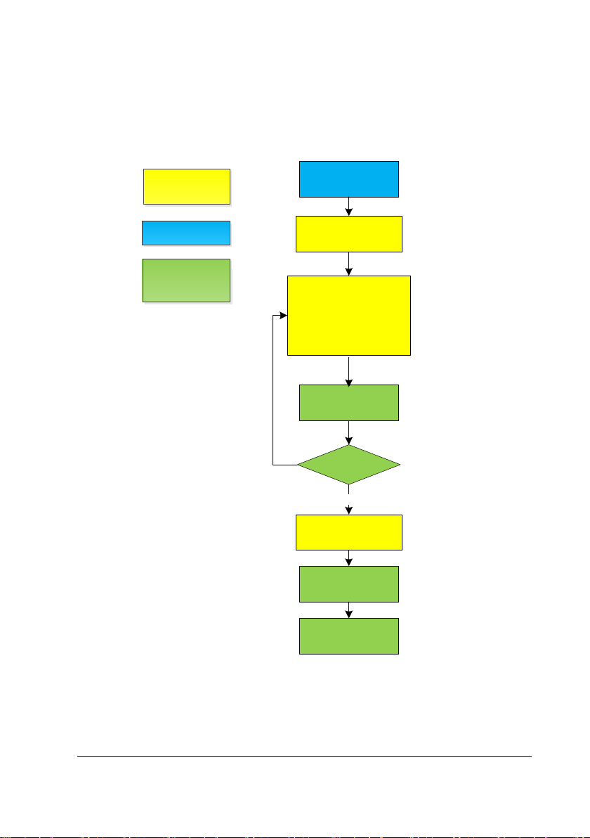
3.1.3.1 Using Hospital’s WLAN
If the hospital has built its WLAN, the installation process is illustrated as follows:
3-4 BeneVision TM80 Telemetry Monitor Service Manual
Page 27

network
List of outputs
Action Output Requirements Template
A0
Basic
requirements
for
Determine specific
requirements for deployment
of the TM80 network.
3.11.1TM80 Wi-Fi
Network
Requirement Table
deployment of
the TM80
A3 Environmental
survey report
Confirm that the wireless
environment of the customer
3.11.2Environmental
Survey Table
meets requirements of the
TM80 by means of
questionnaire and
measurement.
A5 Network
acceptance
report
Confirm that the customer
network meets requirements
of the TM80 by means of
3.11.3Network
Acceptance Table
questionnaire and
measurement.
A6
Sample
verification
confirmation
Confirm the actual operation
of the sample after the sample
is installed.
3.11.4TM80
Verification
Confirmation Table
table
CAUTION
If the customer network cannot meet the requirement in
3.11.2Environmental Survey Table, the service personnel should perform
pilot run of the TM80 for at least 24 hours first to ensure that the wireless
environmentis compatible before signing a contract.
BeneVision TM80 Telemetry Monitor Service Manual 3-5
Page 28

NOTE
Contents in 3.11.2Environmental Survey Table are actually part of
3.11.3Network Acceptance Table. If service personnel have already
performed environmental survey, they can fill the survey results in the
Network Acceptance Tabl e directly.
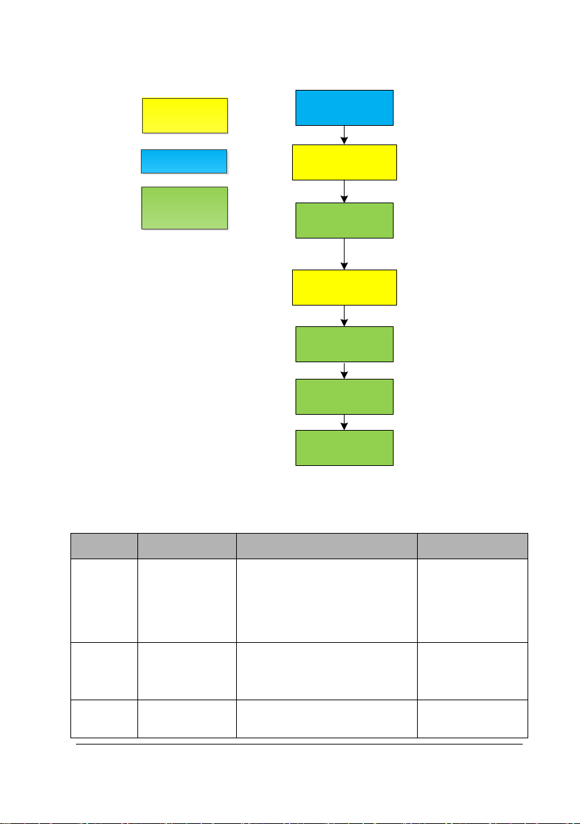
3.1.3.2 Installing New WLAN for TM80
If the hospital plans to build a new WLAN for the TM80, make sure that there is at
least one idle wifi channel that is not in use. Otherwise, you can’t make Co-channel
interference meet TM80’s requirement after the new WLAN is built. The installation
process is illustrated as follows:
3-6 BeneVision TM80 Telemetry Monitor Service Manual
Page 29
network
Mindray/
agent
marketing or s
ales
personnel
Mindray
headquarters
Mindray
/agent
service personnel
A1 Communicate with
the hospital about
intention to order
A5 Install the device
and confirm system
operation
A6
Accept and confirm
with the hospital
A
0 Provide network
requirements
A
4 Install network
A2 Do site survey and
design network
A
3 Sign the contract
List of outputs
Action Output Requirements Template
Basic
A0
A2 Network design
requirements
for deployment
of the TM80
Determine specific
requirements for deployment
of the TM80 network.
/ /
3.11.1TM80 Wi-Fi
Network
Requirement
Table
document,
Bill of material
A5 Network
BeneVision TM80 Telemetry Monitor Service Manual 3-7
acceptance
Confirm that the installed
network meets requirements of
3.11.3Network
Acceptance Table
Page 30

report
the TM80 by means of
self-check and measurement.
A6
Sample
verification
confirmation
table
Confirm the actual operation of
the sample after the sample is
installed.
3.11.4TM80
Verification
Confirmation
Table
NOTE
This manual only shows a reference for installing new WLAN for TM80 in
section 3.7. Network deployment project needs much more complex
process, you need professional IT engneer ’s help to finish the job.
3-8 BeneVision TM80 Telemetry Monitor Service Manual
Page 31

3.2 Network Requirements of the TM80
The TM80 transmits vital signs of patients in real time. The requirements for
real-time and reliability are higher than those for audio and video services. The TM80
is powered by a battery. It adopts low power Wi-Fi technology. Therefore, the
network needs to meet specific requirements to ensure reliable operation.
The network requirements of TM80 can be classified into six types:
Wireless coverage
AP capability and compatibility
WLAN features
EAP Requirement for RADIUS Server and Certs
Network service and VLAN
Some important settings of network device
The first four types are decided by infrastructure of network. They can’t be modified
easily. If the network does not meet the requirements before TM80 is installed,
network dropping-off may happen easily after installation.
The fifth and sixth types belong to configuration of network. They need hospital IT
department’s help to achieve. According to experience of Mindray, the two types
can guarantee reliable performance of TM80 effectively. If any requirement is not
met, network dropping-off may happen in certain situation. If the number of
devices using the same network is small, and no device needs high wireless
bandwidth, the possibility of dropping-off can be reduced.
BeneVision TM80 Telemetry Monitor Service Manual 3-9
Page 32

3.2.1 Requirements for Network Feasibility
Before installing TM80 telemetry monitors, it is very important to confirm network
feasibility.
Wireless coverage, WLAN features and AP capability and compatibility are decided
by infrastructure of network, infrastructure of network can’t be modified easily. If the
network does not meet the requirements before TM80 is installed, network
dropping-off may happen easily after installation.
3.2.1.1 Requirements for the Wireless Coverage
The wireless coverage must be well controlled to ensure that TM80 can achieve the
maximum data-rate and the lowest packet loss ratio. TM80 data is real-time
upstream data streams and is similar to VoIP data. Monitoring data carries real-time
physiologic information about patients. Therefore, reasonable wireless coverage
must be provided for monitors. In particular, because the telemetry device TM80 is
worn on human body, the signal may become poorer due to blocking of human
body.
The requirements of the TM80 for wireless coverage are as follows:
No. Item Requirements of the TM80 Description
1 Received
signal
strengths
(RSSI)
2 Co-channel
interference*
3 Ping delay The mean delay of PC or cell phone
3-10 BeneVision TM80 Telemetry Monitor Service Manual
≥-65 dBm
Signal coverage requirement for APs
connected to the TM80: RSSI value
displayed on the TM80
≤-20dB
Measured on the same channel of
the TM80
with normal wifi module is smaller
than 100ms and the packet lost rate
The requirement
must be met.
The requirement
must be met.
The requirement
must be met.
Page 33
No. Item Requirements of the TM80 Description
shall be less than 1%.
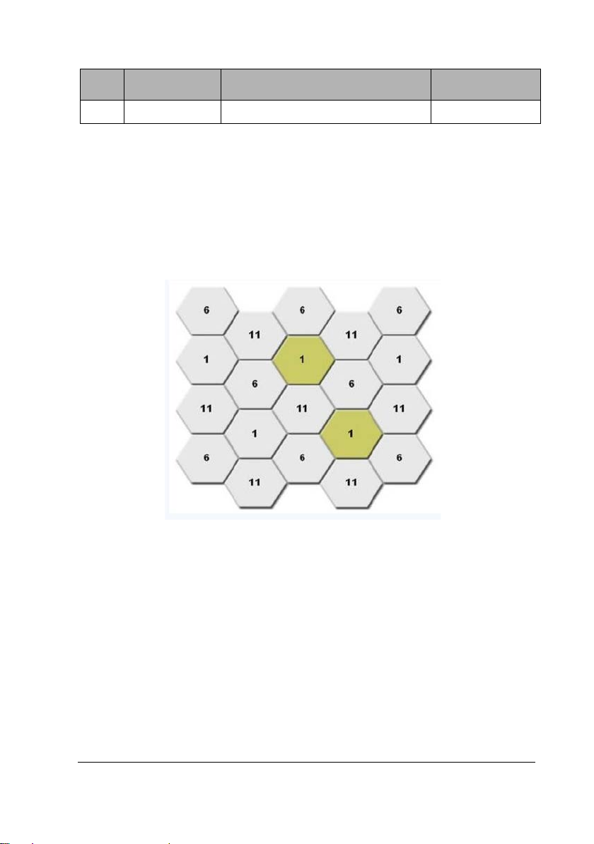
Co-channel interference is the most obvious interference for Wi-Fi. The signal
strength of the nearest AP perceived by the wireless monitor must be 20 dB higher
than that of other APs on the same channel. Take 2.4 GHz band as an example. The
following channel deployment is recommended to realize Wi-Fi coverage similar to
cellular coverage.
For co-channel interference, the interference between floors needs to be considered
and the following case should be avoided: a pair of APs is set nearby between two
floors and is working on the same channel. Different SSIDs of the same AP do not
generate co-channel interference (CCI) . CCI from different AP but Same SSID can be
accepted in 2.4G band, but this is highly recommended to be avoided.
3.2.1.2 Requirements for the AP capability
Because the low-power WIFI module is sleeping periodically and the capability for
dealing with wireless data is reduced, it is necessary to use high-performance AP to
BeneVision TM80 Telemetry Monitor Service Manual 3-11
Page 34

enhance the stability of total system. Mindray tested a lot with TM80 and Cisco APs,
the compatibility of Cisco AP is proven good.
We recommend using the network equipment verified by Mindray. This verification
activity includes confirmation of network architecture, equipment model, firmware
version, and specific configurations.
If network equipment whose compatibility is not confirmed by Mindray is used,
potential risks may exist during operation of the TM80. In this case, Mindray
recommends the customer to perform pilot run of the TM80 for at least 24 hours
first to ensure that the equipment is compatible.
Device density needs to be controlled. If too many devices are mounted under one
AP, competition among devices becomes fiercer. For low power consumption Wi-Fi,
high data loss probability will be caused. Therefore, the number of devices under
the same AP must be controlled. The TM80 requires one AP to mount a maximum of
16 devices.
No. Item Requirements of the TM80 Description
1 Recommended
AP
Mindray’s recommendations:
Cisco: WLC 2504 (version 7-4-121-0 or
Nice to meet
later) + LAP: 2802 or 2602
or FAT AP:2602
Aruba:7500 series+LAP:APIN0205
Netgear:WNDAP350
Notes: If the AP is 2802 or
WNDAP350,TM80 can only use 5G
2 AP capability 1.The anticipated number of devices
connecting to one AP must be
lower than the AP capability ,and
The
requirement
must be met.
3-12 BeneVision TM80 Telemetry Monitor Service Manual
Page 35

No. Item Requirements of the TM80 Description
capability should has a margin of
50%. For example, In the coverage of
one AP, the typical number of devices
connected to this AP is 16, then the
announced number of devices than
can connect to AP simultaneously
must be more than 32.
2. The AP Can create several SSIDs.
3 Device density The maximum number of devices
connected to one AP simultaneously
is 16 (including TM80 and other
devices).
4 AP
compatibility
When customer using APs not from
Cisco, compatibility test should be
passed
The
requirement
must be met.
The
requirement
must be met.
3.2.1.3 Requirements for WLAN Features
The requirements of the TM80 for WLAN features are as follows. If WLAN is of other
features, e.g. using 802.11ac, TM80 will not support, and can't connect to network.
The TM80 adopts low power consumption Wi-Fi technology. If the amount of
broadcast or multicast data is too large on the network, the device wake-up time
increases, the standby duration is shortened, and even Wi-Fi transmission
interruption is caused. Therefore, the TM80 must use an independent VLAN and
work in a different network segment from the CMS, so as to control the amount of
broadcast data. An AP can be configured with multiple SSIDs and associated with a
VLAN. The TM80 needs to use an independent SSID.
BeneVision TM80 Telemetry Monitor Service Manual 3-13
Page 36

No. Item Requirements of the TM80 Description
1 802.11
protocol
2 Security
mode
TM80 only support 802.11 a/b/g/n,
WLAN can't use other protocols
TM80 supports:
WPA/WPA2-PSK or WPA2-Enterprise
EAP method:
PEAP-GTC, PEAP- MSCHAPv2,EAP-TLS
WPA2-PSK is highly recommended.
WPA2-Enterprise may increase
probability of offline when roaming, so
not be recommended.
WLAN can't use other security mode.
3 AP MAC
address
The broadcast MAC address of AP is
fixed (BSSID).
AP BSSID is used to locate the TM80
device. If it is changed, failure to locate
the TM80 may occur.
4 AP channel
width
If the AP supports 802.11n/ac, set the
channel width to 20Mhz, don’t use HT40
or even HT80.
5 Dedicated
VLAN
The TM80 needs to work on a dedicated
VLAN.
Using VLAN can minimize Broadcast or
multicast data which can affect TM80
stability.
The requirement
must be met.
The requirement
must be met.
The requirement
must be met.
The requirement
must be met.
The requirement
must be met.
3-14 BeneVision TM80 Telemetry Monitor Service Manual
Page 37

TLS_RSA_WITH_RC4_128_MD5
TLS_RSA_WITH_RC4_128_MD5
Free
PEAP-MSCHAPV
TLS_ECDHE_RSA_WITH_AES_128_CBC_SH
3.2.1.4 EAP Requirements for RADIUS Server and Certs
RADIUS Server
The following RADIUS Server is validated by Mindray:
Cisco ACS
FreeRADIUS
Network Policy Service( in Windows Server 2008 R2 and Windows Server 2012 R2)
Algorithm
The following table list the EAP methods and TLS1.0 algorithm that TM80 supported
for each RADIUS Server:
RADIUS
Server
NPS PEAP-MSCHAPV
ACS PEAP-MSCHAPV
EAP Methods TLS Cipher Suites
2
EAP-TLS
2
PEAP-GTC
EAP-TLS
TLS_ECDHE_RSA_WITH_AES_128_CBC_SH
A_P256
TLS_ECDHE_RSA_WITH_AES_256_CBC_SH
A_P256
TLS_RSA_WITH_AES_256_CBC_SHA
TLS_RSA_WITH_AES_128_CBC_SHA
TLS_RSA_WITH_3DES_EDE_CBC_SHA
TLS_RSA_WITH_RC4_128_SHA
TLS_ECDHE_RSA_WITH_AES_128_CBC_SH
A(Elliptic curve: secp256r1)
TLS_ECDHE_RSA_WITH_AES_256_CBC_SH
A(Elliptic curve: secp256r1 )
TLS_DHE_RSA_WITH_AES_256_CBC_SHA
TLS_DHE_RSA_WITH_AES_128_CBC_SHA
TLS_DHE_RSA_WITH_3DES_EDE_CBC_SHA
TLS_RSA_WITH_AES_256_CBC_SHA
TLS_RSA_WITH_AES_128_CBC_SHA
TLS_RSA_WITH_3DES_EDE_CBC_SHA
TLS_RSA_WITH_RC4_128_SHA
BeneVision TM80 Telemetry Monitor Service Manual 3-15
Page 38

TLS_RSA_WITH_RC4_128_MD5
RADIUS
EAP Methods TLS Cipher Suites
Server
RADIUS 2
A(Elliptic curve: secp256r1)
PEAP-GTC
EAP-TLS
A(Elliptic curve: secp256r1 )
Certification:
The general requirements for the CA Cert:
Supported Public Key Algorithm: RSA
Supported Key Size: 512, 1024, 2048
Supported Hash Algorithm: SHA1 and MD5
TLS_ECDHE_RSA_WITH_AES_256_CBC_SH
TLS_DHE_RSA_WITH_AES_256_CBC_SHA
TLS_DHE_RSA_WITH_AES_128_CBC_SHA
TLS_DHE_RSA_WITH_3DES_EDE_CBC_SHA
TLS_RSA_WITH_AES_256_CBC_SHA
TLS_RSA_WITH_AES_128_CBC_SHA
TLS_RSA_WITH_3DES_EDE_CBC_SHA
TLS_RSA_WITH_RC4_128_SHA
Supported File Format: PEM(.PEM)
Do not support certification chain and CRL
The general requirements for the User Cert:
This User Cert should contain both the user certification and the unencrypted
pkcs#8 private key
Supported Key Algorithm: RSA
Supported Key Size: 512, 1024, 2048
Supported Hash Algorithm: SHA1 and MD5
Supported File Format: PEM(.PEM)
3-16 BeneVision TM80 Telemetry Monitor Service Manual
Page 39
The specified requirement for FreeRADIUS:
The supported algorithm used to encrypt the keys of CA and User Cert: 3DES,
AES128, AES256
The requirement for DH file on FreeRadius:
1. The number bits of the DH file should be: 512, 1024, 2048
2. The DH file should not be generated with dsaparam.
3. The DH file size should less than 2K bytes
Specified requirements:
The specified requirement for ACS:
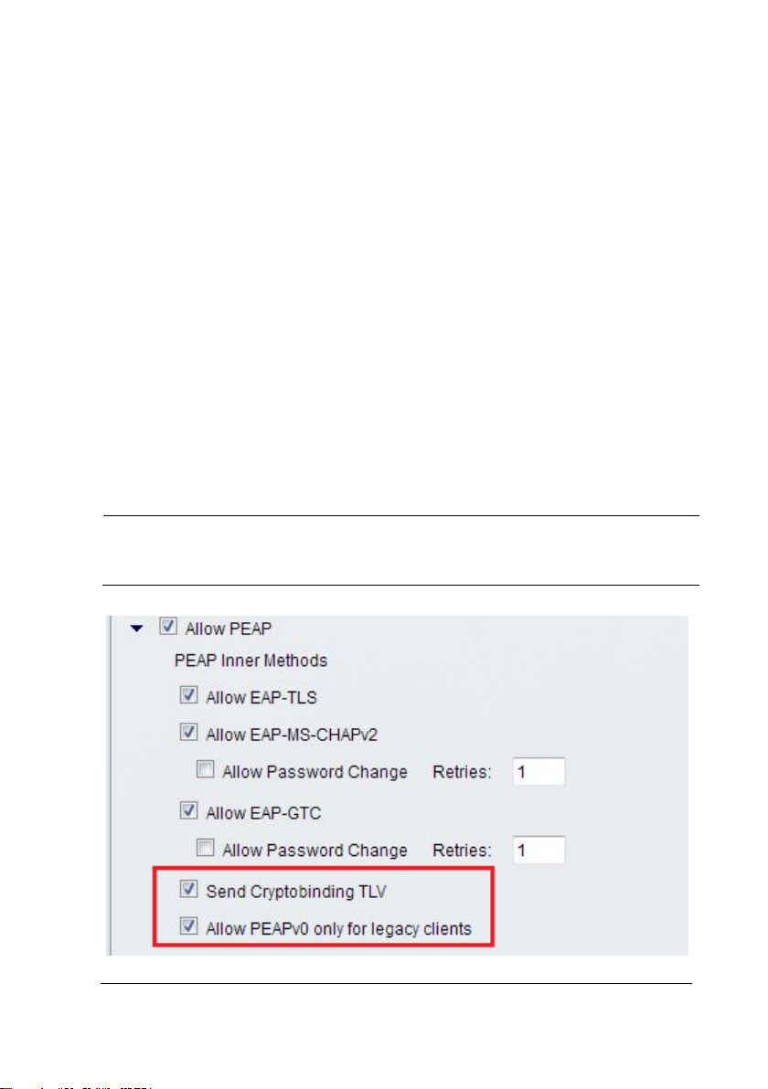
On the page of Access Policy ->Access Services->Allowed Protocols
NOTE
DO NOT check both "Send Crypto binding TLV" and "Allow PEAPv0 only
for legacy clients".
BeneVision TM80 Telemetry Monitor Service Manual 3-17
Page 40
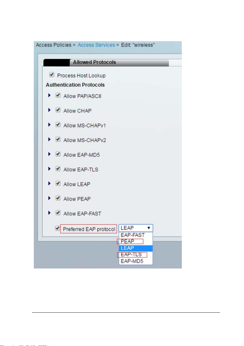
"Preferred EAP protocol" should set to PEAP or EAP-TLS.
3-18 BeneVision TM80 Telemetry Monitor Service Manual
Page 41

3.2.2 Configuration Requirements for WLAN of TM80
Requirements include two types: Network service andVLAN, some important
settings of network device.
3.2.2.1 Network Service andVLAN
No. Item Requirements of the TM80 Description
1 Port UDP ports 5500 and 6678 are enabled.
TCP ports 6587 and 7779 are enabled.
2 VLAN
bandwidth
3 Network
continuity
Service port
The TM80 needs UDP ports 5500 and 6678 and TCP ports 6587 and 7779 on
the network to be enabled so as to ensure that the TM80 can be discovered by
the CMS, establish network connections, and transmit monitoring data.
Bandwidth
The planned bandwidth of TM80 must
be larger than N*100 kbps (N is the
number of installed TM80 products).
For example, if 10 TM80 products are
working at the same time, the VLAN
needs to meet the bandwidth of 1000
kbps.
In the coverage area of TM80, the
network belongs to the same WLAN. All
APs use the same SSID and encryption
mode.
The requirement
must be met.
The requirement
must be met.
The requirement
must be met.
The VLAN serving the TM80 may share wired network trunks with other VLANs.
The hospital must ensure that bandwidth utilization of trunks does not exceed
80%. If the bandwidth of a VLAN can be configured, the bandwidth configured
for the VLAN serving the TM80 is recommended to be decreased by 50%. If 10
BeneVision TM80 Telemetry Monitor Service Manual 3-19
Page 42

snooping
enable IGMP snooping.
must be met.
,
must be set to the highest level.
TM80s are working at the same time, VLAN bandwidth must be larger than
1Mbps, better to be greater than 2Mbps.
Network continuity
TM80 needs to roam across Aps. TM80 can’t roam across different IP subnet and
different SSID;
3.2.2.2 Some Important Settings of Network Device
No. Item Requirements of the TM80 Description
1 DHCP The DHCP server reserves a
sufficient number of IP addresses for the
telemetry VLAN to ensure that the TM80
can obtain an IP address.
2 IGMP
3 Multic
ast
4 Beaco
n & DTIM
5 AP
data rate
6 QOS The switch or router must support
The configuration of wireless devices is critical to reliable operation of Mindray
monitors. Special attention needs to be paid to the following items:
DHCP
The WLC is not recommended to be used as DHCP server. It is recommended to
enable the WLC DHCP agent function. A dedicated DHCP server is used to
assign IP addresses. The DHCP server needs to reserve a sufficient number of IP
If CMS accepts TM80, use multicast,
The multicast function is enabled.
Otherwise, the TM80 can only connect
to the CMS in unicast mode.
AP DTIM = 1, Beacon = 100ms The
Close the data rate of
1Mbps
2Mbps,5.5Mbps in 802.11b
QoS and the QoS level of TM80's subnet
The
requirement
must be met.
Nice to meet
The
requirement
must be met.
requirement
Nice to meet
Nice to meet
3-20 BeneVision TM80 Telemetry Monitor Service Manual
Page 43

addresses for the telemetry VLAN to ensure that the TM80 can obtain an IP
address. If static IP addresses are used, make sure that the IP address of each
device is unique.
Multicast
The TM80 transmits device discovery packets over UDP so that the CMS can discover
it and establish a connection. Transmission over UDP can be in multicast or
unicast mode. If the customer uses the multicast mode, multicast transmission
must be enabled on the network. IGMP snooping must be enabled to avoid
transmitting unwanted multicast data to the TM80.
DTIM
Set DTIM = 1, Beacon = 100ms for TM80 vlan.TM80 is working under low-power
mode and waked up by according to AP’s DTIM. If the DTIM is too long, TM80
need more time to wake up so that the throughput become lower, the
probability of offline may increase.
Data rate
If the network supports the low data rate, the channel will become crowded .As a
result, the probability of offline may increase.
IF low data rate are closed, be sure that the RF coverage meet TM80’s requirement.
BeneVision TM80 Telemetry Monitor Service Manual 3-21
Page 44

Quality of Service (QoS)
If the network is used by TM80 and other devices at the same time, it’s
recommended that the QoS level of the SSID and VLAN used by TM80 is set to
highest level to make sure that the data is real-time.
3.3 Configuration of Cisco Network Devices
This section describes how to configure Cisco WLC and APs to meet wireless
networking requirements of Mindray telemetry monitors. It consists of two parts: list
of supported network devices and specific configuration requirements.
Because the IT infrastructures of different hospitals are different, below
configuration is only for your reference. You need to modify the configuration
according to your hospital IT department.
3.3.1 Recommended Devices
WLC: Cisco 2500series
AP: Cisco 2802 0r 2602
3-22 BeneVision TM80 Telemetry Monitor Service Manual
Page 45
3.3.2 Configuration Description
3.3.2.3 Login
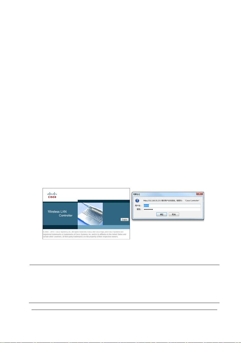
On the command line interface (CLI), set the IP address of the WLC to 192.168.30.253
and subnet mask to 255.25.255.0 and enable login on the web page. Set the user
name for login to admin and the passcode to Cisco123. The user name and
passcode should be set in a unified way so as to facilitate maintenance and change
of the configuration later.
Set the IPv4 address of the PC to 192.168.30.1 and the subnet mask to 255.255.255.0
and connect the network port of the PC to port 1 of the WLC by using a network
cable.
Considering compatibility with the AC, Firefox browser is preferred. Internet Explorer
is secondly preferred. Enter https://192.168.0.253 in the address bar and choose to
trust the website. On the login page, click Login and enter the user name and
passcode to access the configuration page. Figure 1 shows the login page.
NOTE
Although the default settings of some WLCs are not changed, the specific
settings are displayed during setup due to the importance of
configuration. The operator just needs to confirm the settings without the
need to change them. If no specific description is provided during setup,
BeneVision TM80 Telemetry Monitor Service Manual 3-23
Page 46
retain the default settings of WLC.
After logging to the WLC, configure the WLC by performing the following steps:
1. Set the WLAN. This part includes SSID creation, General setting, Security setting,
QoS setting, and Advanced setting.
2. Set CONTROLLER. This part includes the General setting and Multicast setting.
3. Set WIRELESS. This part includes the setting of 802.11b/g/n and setting of APs.
3.3.3 WLAN Settings
3.3.3.1 Creating an SSID
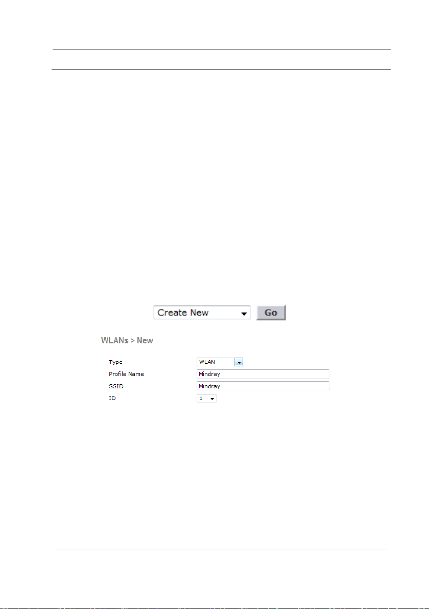
1. Choose WLANs→New. The configuration page is displayed.
2. Perform the following configuration on the page, as shown below.
3. Click Apply and Save Configuration.
3-24 BeneVision TM80 Telemetry Monitor Service Manual
Page 47
3.3.3.2 General Settings
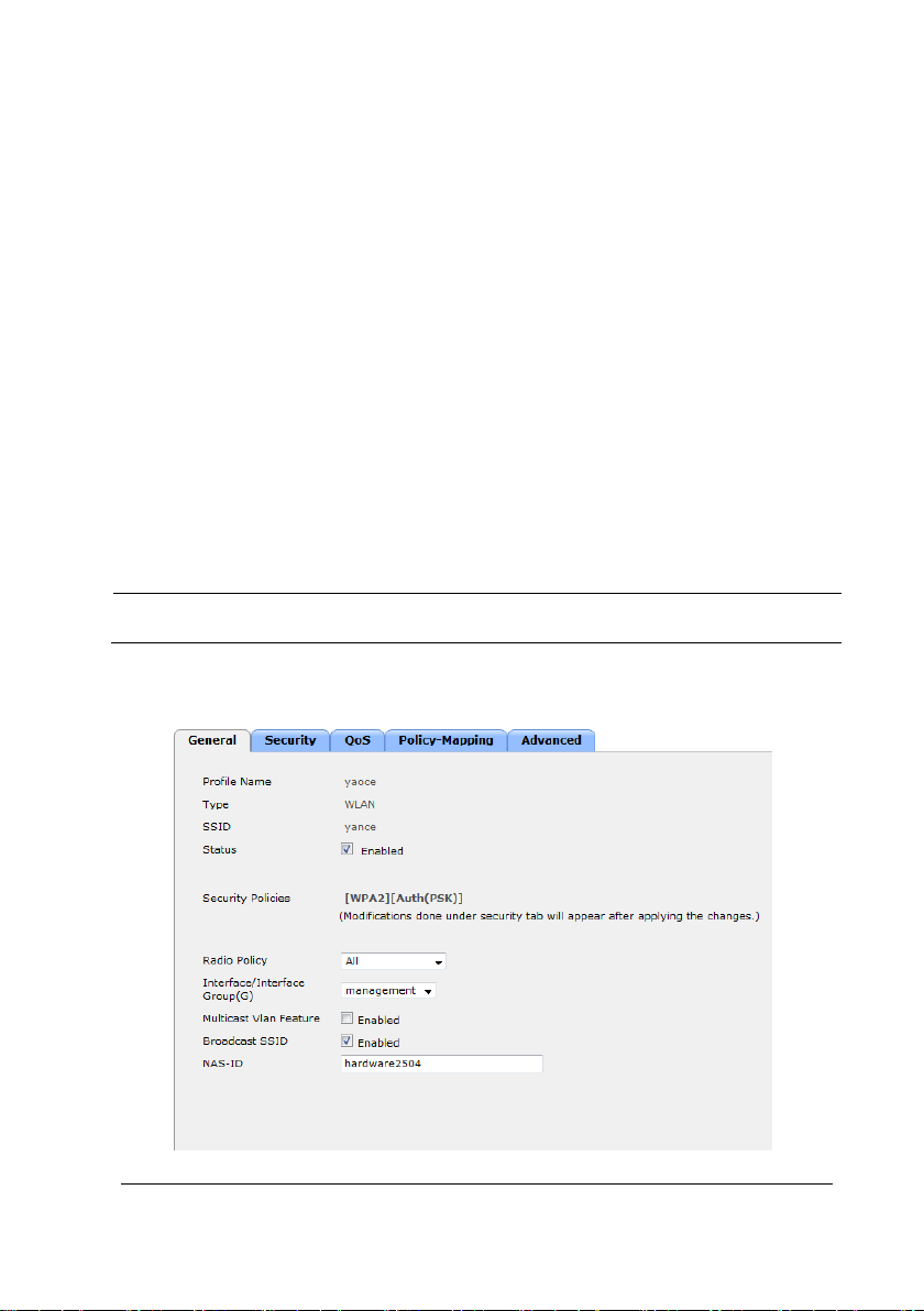
1. On the page, enable the WLAN, select a protocol supported by the WLAN,
select the VLAN where the WLAN is located, and enable broadcast SSID.
2. Choose WLANs→WLAN ID→General. The configuration page is displayed.
3. Perform the following configuration on the page.
Status=Enabled
Radio policy=All
Interface/Interface Group=VLAN ID
Broadcast SSID=Enabled
NOTE
Select the VLAN corresponding to the SSID for VLAN ID.
The figure below shows the specific General configuration.
BeneVision TM80 Telemetry Monitor Service Manual 3-25
Page 48
4. Click Apply and Save Configuration.
3.3.3.3 Security Settings
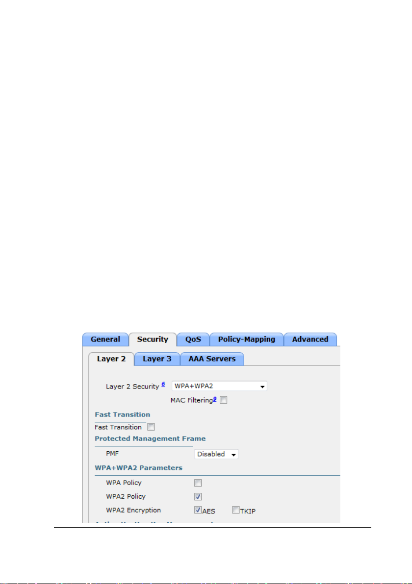
On the page, configure WLAN security and encrypt physiological information of
patients.
1. Choose WLANs→WLAN ID→Security→Layer 2. The configuration page is
displayed.
2. Perform the following configuration on the page.
Layer 2 Security=WPA+WPA2
MAC Filter=Disabled
WPA Policy=Disabled
WPA2 Policy=Enabled
WPA2 Encryption=AES
Authentication Key Management=PSK
PSK Format=ASCII
The figure below shows the specific Security configuration.
3-26 BeneVision TM80 Telemetry Monitor Service Manual
Page 49
3. Click Apply and Save Configuration.
3.3.3.4 QoS Settings
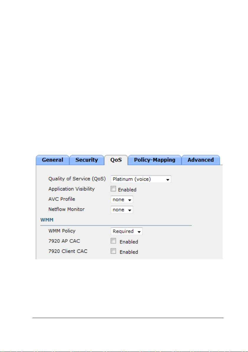
On the page, set QoS. By default, the WLC considers all frames in the WLAN as
ordinary data and adopts the best-effort processing mode. However, the
physiological data of patients has the highest priority.
1. Choose WLANs→WLAN ID→QoS. The configuration page is displayed.
2. Perform the following configuration on the page.
Quality of Service(Qos)=Platinum(voice)
WMM Policy=Required
The figure below shows the specific QoS configuration.
3. Click Apply and Save Configuration.
BeneVision TM80 Telemetry Monitor Service Manual 3-27
Page 50

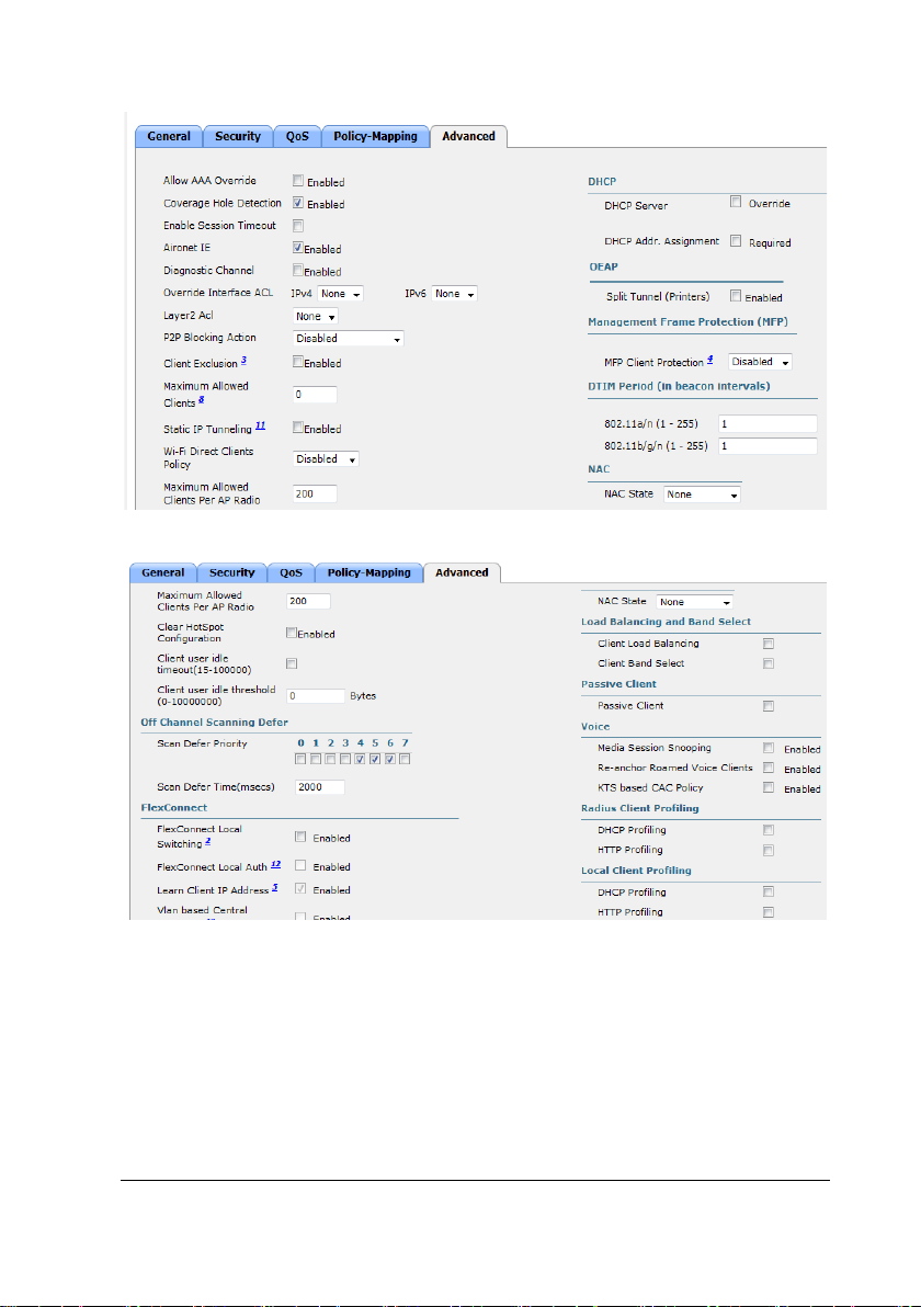
3.3.3.5 Advanced Settings
On the page, various advanced WLAN settings can be configured, including
disabling coverage hole detection, disabling customer exclusion, disabling load
balancing, and enabling Off Channel Scan.
1. Choose WLANs→WLAN ID→Advanced. The configuration page is displayed.
2. Perform the following configuration on the page.
Coverage Hole detection=Enabled
Enable Session Timeout=Disabled
Aironet IE=Enabled
Customer Exclusion=Disabled
Scan Defer Priority=Enable only 6 and 7
Scan Defer Time(msecs)=2000
DHCP Server(override)=Disabled
DHCP Addr. Assignment=Disabled
Management Frame Protection(MFP)=Disabled
802.11a/n(1-255)=1
802.11b/g/n(1-255)=1
Customer Load Balancing=Disabled
Customer Band Select=Disabled
The figures below show the specific Advanced configuration.
3-28 BeneVision TM80 Telemetry Monitor Service Manual
Page 51
3. Click Apply and Save Configuration.
3.3.4 CONTROLLER Settings
In the CONTROLLER directory, enable broadcast and multicast.
BeneVision TM80 Telemetry Monitor Service Manual 3-29
Page 52
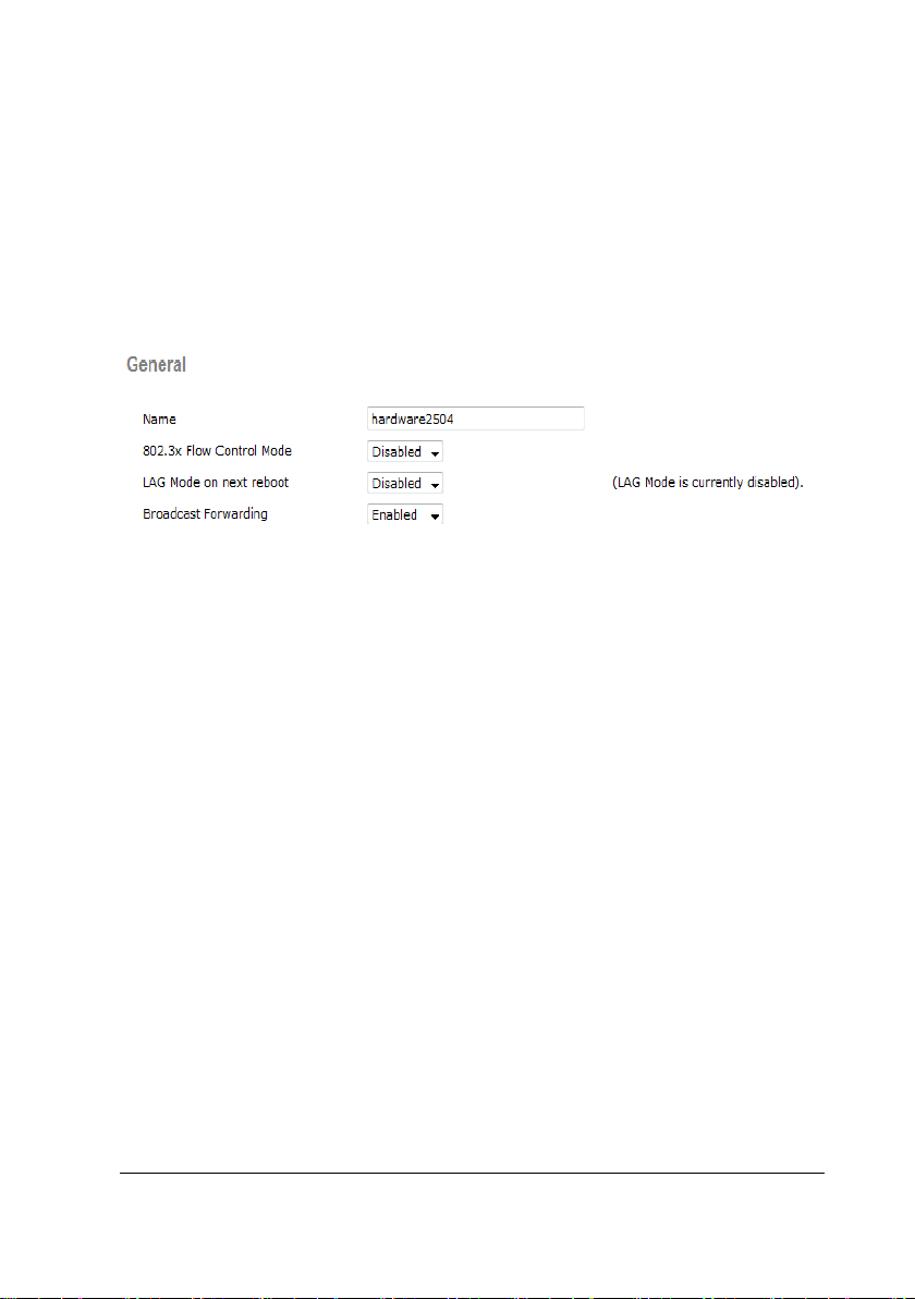
3.3.4.1 General Settings
1. Choose CONTROLLER→General. The configuration page is displayed.
2. Perform the following configuration on the page.
Broadcast Forwarding=Enable
The figure below shows the specific General configuration.
3. Click Apply and Save Configuration.
3.3.4.2 Multicast Settings
1. Choose CONTROLLER→Multicast. The configuration page is displayed.
2. Perform the following configuration on the page.
Enable Global Multicast Mode=Enabled
Enable IGMP Snooping=Enabled
3-30 BeneVision TM80 Telemetry Monitor Service Manual
Page 53
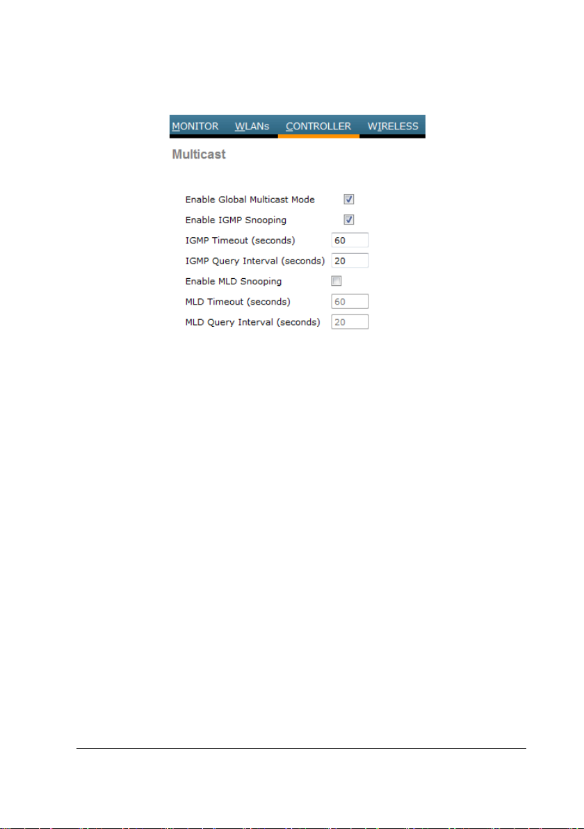
The figure below shows the specific Multicast configuration.
3. Click Apply and Save Configuration.
3.3.5 WIRELESS Settings
In the CONTROLLER directory, you can enable 2.4G and 5G bandwidth, configure the
data rate, configure support for 802.11N, and set RRM to optimize the wireless
environment.
This section describes configuration of 802.11b/g/n. Because the configuration
option of 802.11a/nis similar to this configuration, this configuration is not
described in detail here.
BeneVision TM80 Telemetry Monitor Service Manual 3-31
Page 54
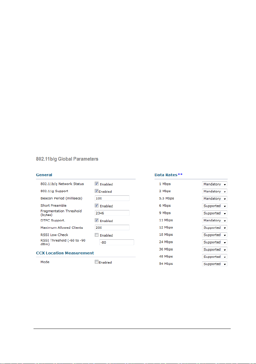
3.3.5.1 Setting 802.11b/g/n (2.4G)
Network Settings
On the page, enable 2.4G and configure the data rate.
1. Choose WIRELESS→802.11b/g/n→Network. The configuration page is
displayed.
2. Perform the following configuration on the page.
802.11b/g Network Status=Enabled
802.11g=Enabled
Data Rates: Set 1Mbps, 2Mbps, 5.5Mbps, and 11Mbps to
Mandatory and other items to Supported.
The figure below shows the specific Network configuration.
3. Click Apply and Save Configuration.
RRM Settings
The RRM provides multiple algorithms and can automatically adjust the transmit
power, channel number, and coverage according to the wireless environment to
3-32 BeneVision TM80 Telemetry Monitor Service Manual
Page 55
optimize the wireless environment.
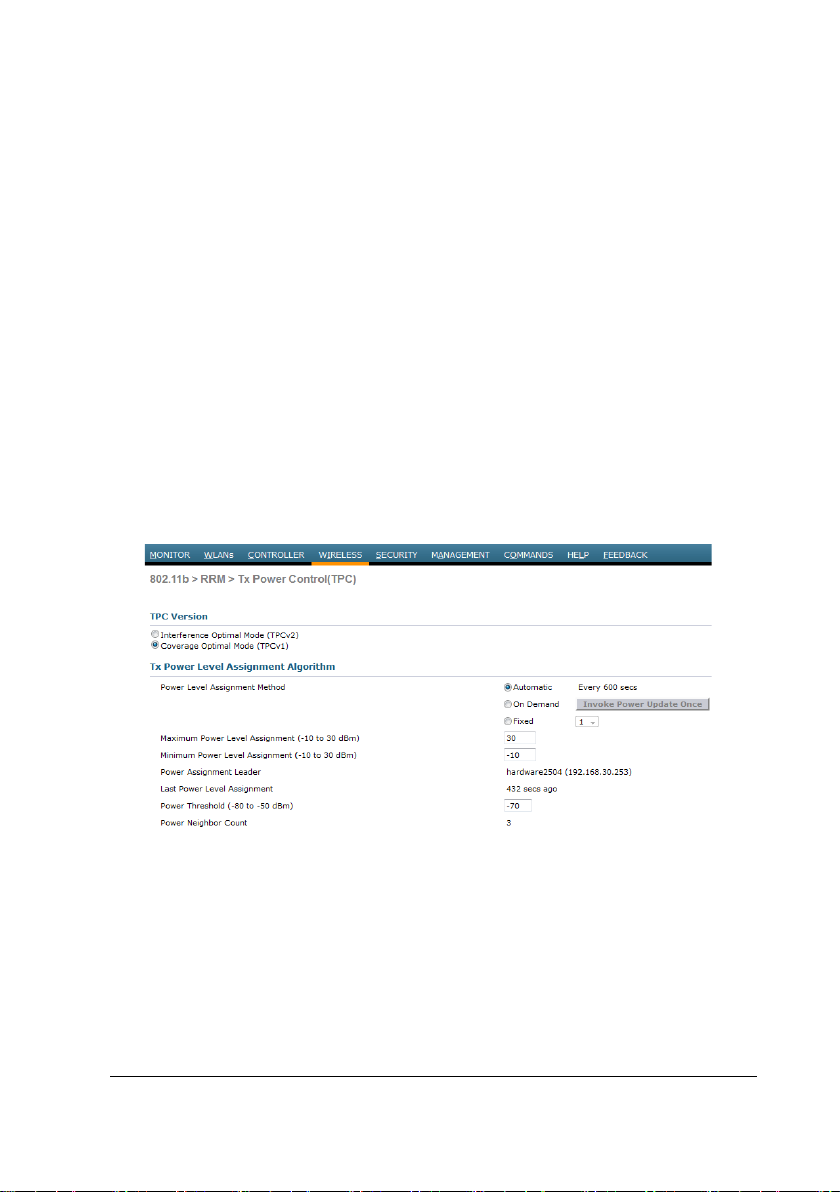
TPC Setting
On the page, enable dynamic transmit power adjustment and select the TPC
algorithm.
1. Choose WIRELESS→802.11b/g/n→RRM→TPC. The configuration page
is displayed.
2. Perform the following configuration on the page.
TPC Version=Coverage Optimal Mode (TPCv1)
Power Level Assignment Method=Automatic
The figure below shows the specific TPC configuration.
3. Click Apply and Save Configuration.
DCA settings
On the page, enable dynamic channel adjustment and set the range of adjustable
channels, start time for adjustment, and interval.
BeneVision TM80 Telemetry Monitor Service Manual 3-33
Page 56
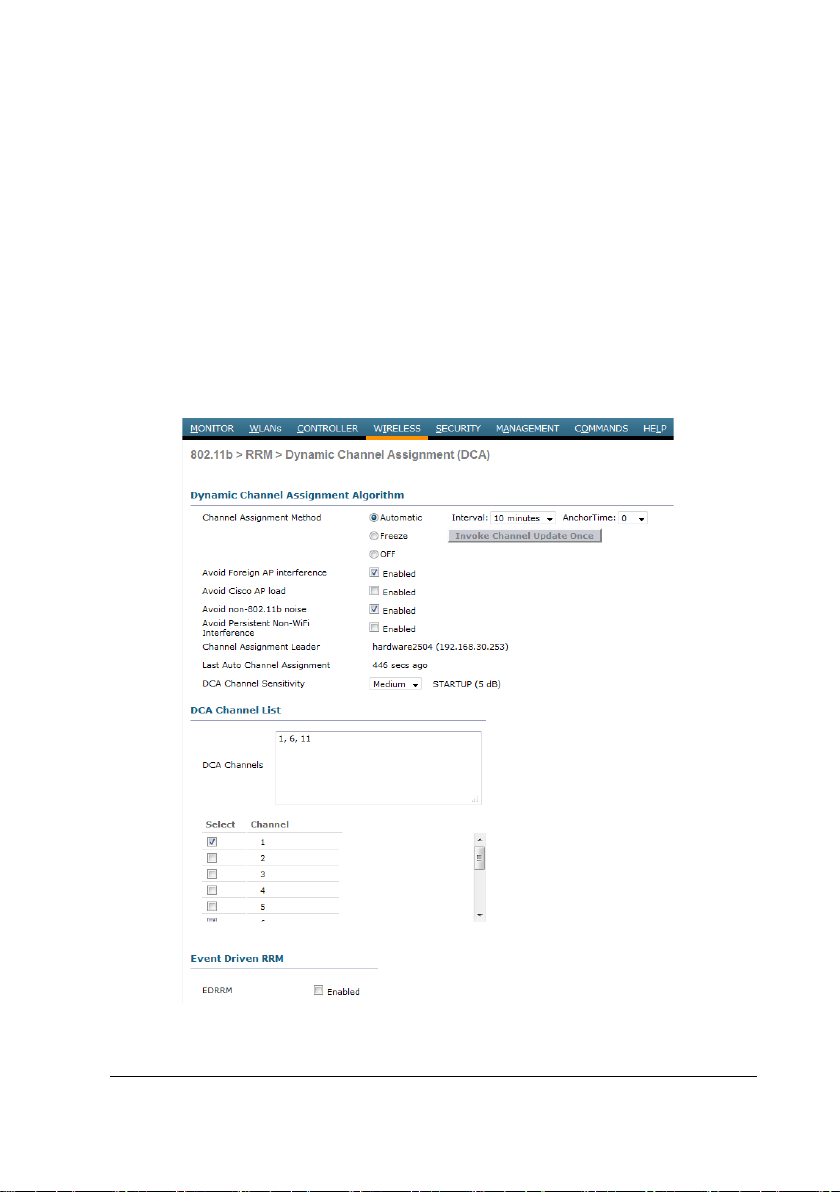
1. Choose WIRELESS→802.11b/g/n→RRM→DCA. The configuration page
is displayed.
2. Perform the following configuration on the page.
Channel Assignment Method=Automatic (interval needs to be 8
hours or more, anchor time= 0)
DCA Channel List=1, 6, 11
The figure below shows the specific DCA configuration.
3. Click Apply and Save Configuration.
3-34 BeneVision TM80 Telemetry Monitor Service Manual
Page 57
NOTE
When configure the 802.11a/an DCA channel list, the DFS channel mustn't
be in the list .For example,The channel list mustn't include the 52~64 and
100~140 in US.
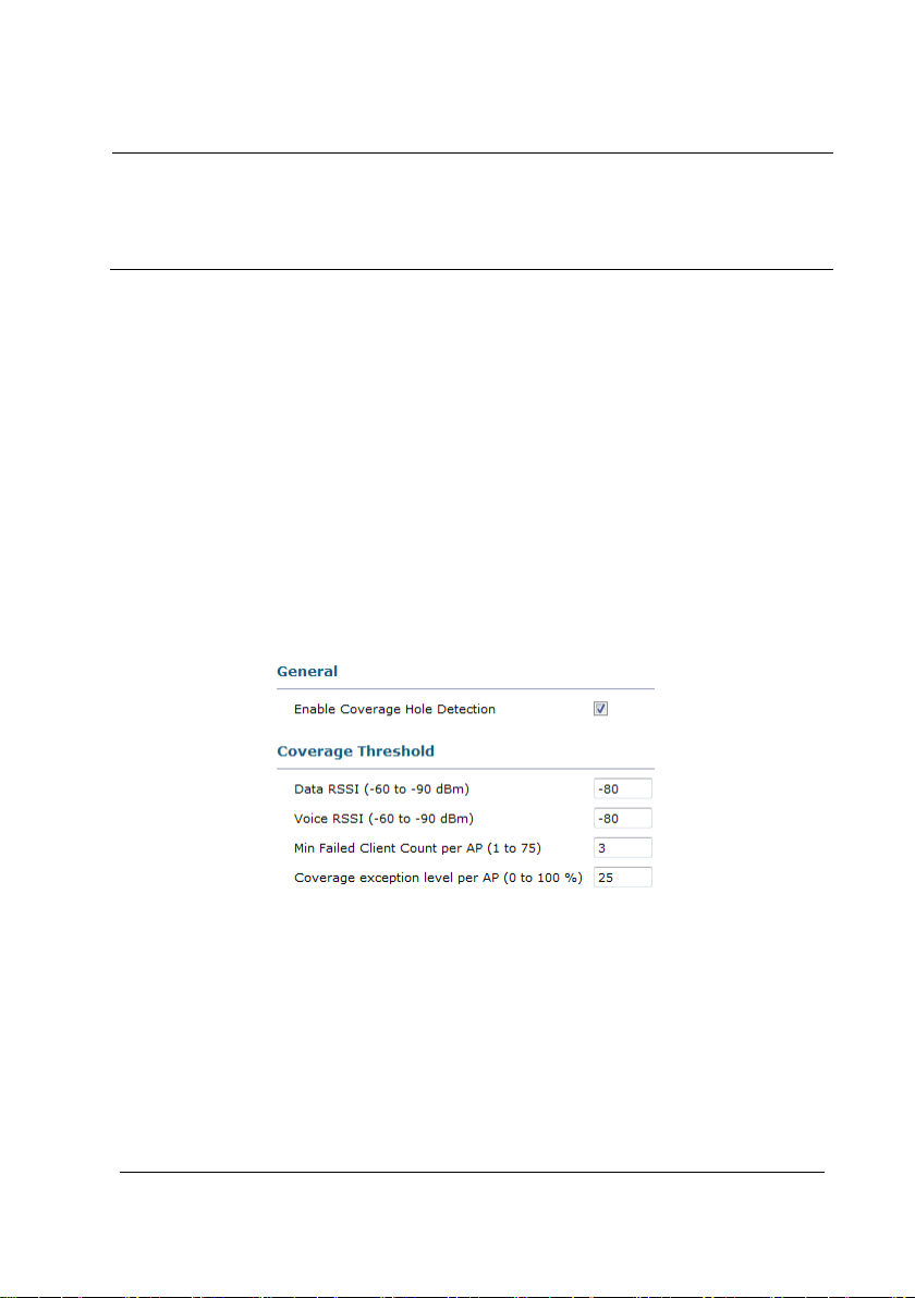
Coverage Settings
On the page, enable coverage hole detection and set the detection standard.
1. Choose WIRELESS→802.11b/g/n→RRM→Coverage. The configuration
page is displayed.
2. Perform the following configuration on the page.
Enable Coverage Hole Detection=Enabled
The figure below shows the specific Coverage configuration.
3. Click Apply and Save Configuration.
3.3.5.2 Setting Access Points (2.4G)
1. Choose WIRELESS→Access Point→Radio→802.11b/g/n. The
configuration page is displayed.
2. Perform the following configuration on the page.
BeneVision TM80 Telemetry Monitor Service Manual 3-35
Page 58
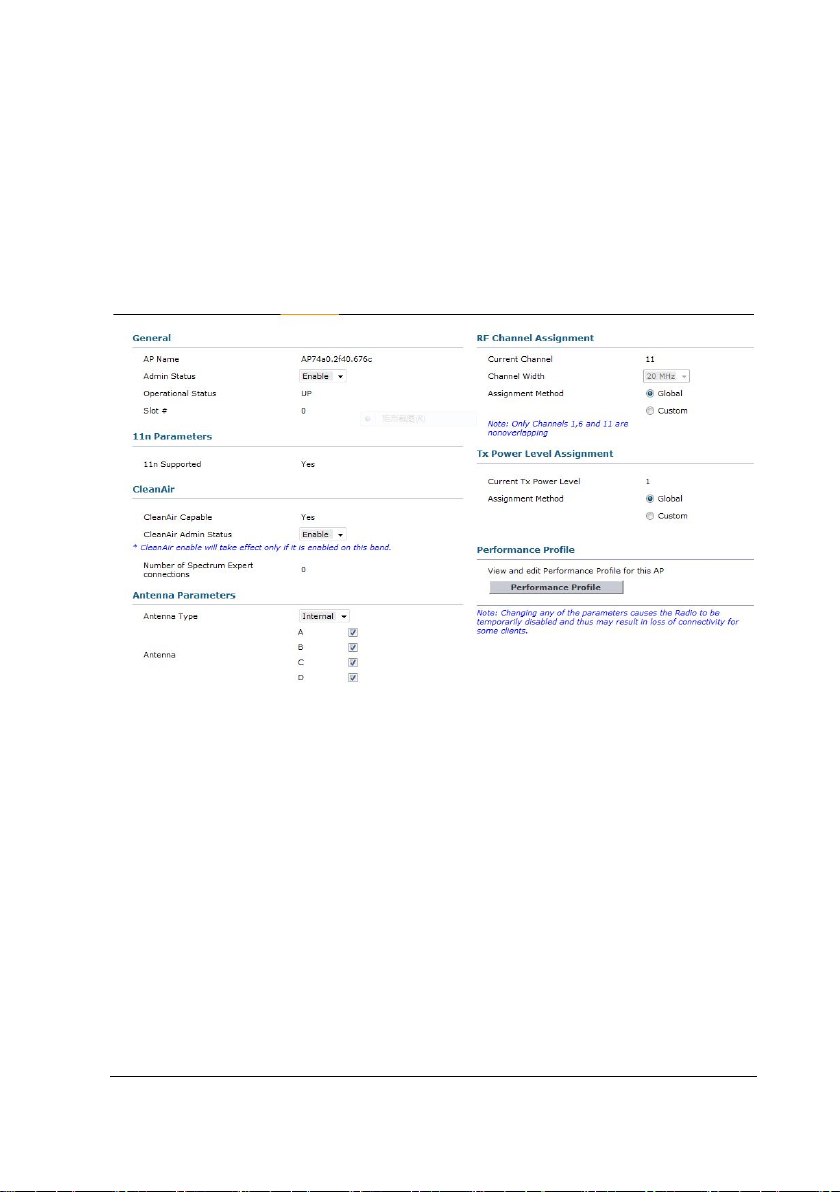
Admin Status=Enabled
RF Channel Assignment(Assignment method)=Global
Tx Power Level Assignment(Assignment method)=Global
The figure below shows the specific AP configuration.
3. Click Apply and Save Configuration.
3.4 Configuration of Aruba Network Devices
This section describes how to configure Aruba WLC and APs to meet wireless
networking requirements of Mindray telemetry monitors. It consists of two parts: list
of supported network devices and specific configuration requirements.
Because the IT infrastructures of different hospitals are different, below
configuration is only for your reference. You need to modify the configuration
according to your hospital IT department.
3-36 BeneVision TM80 Telemetry Monitor Service Manual
Page 59

3.4.1 Recommended Devices
WLC: Aruba 7005 series
AP: Aruba APIN0205
3.4.2 Login
On the command line interface (CLI), set the IP address of the WLC to 192.168.30.253
and subnet mask to 255.25.255.0, and enable login on the web page. Set the user
name for login to admin and the password to aruba123. The user name and
password should be set in a unified way so as to facilitate maintenance and change
of the configuration later.
Set the IPv4 address of the PC to 192.168.0.1 and the subnet mask to 255.255.255.0
and connect the network port of the PC to port 1 of the WLC by using a network
cable.
Considering compatibility with the WLC, Firefox browser is preferred. Internet
Explorer is secondly preferred. Enter https://192.168.0.253 in the address bar and
choose to trust the website. On the login page, click Login and enter the user name
and password to access the configuration page. Figure 1 shows the login page.
BeneVision TM80 Telemetry Monitor Service Manual 3-37
Page 60
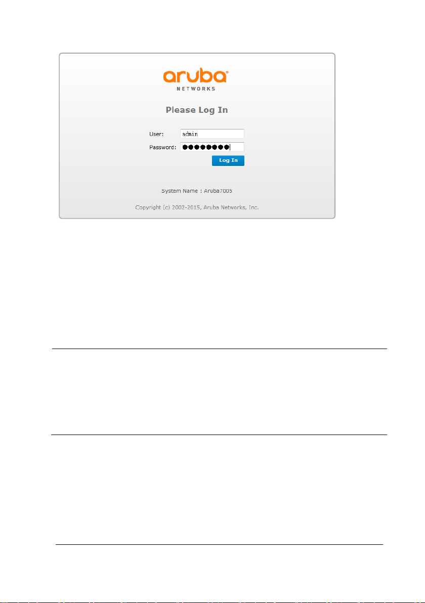
After logging to the WLC, configure the WLC by performing the following steps:
1. Set the Wireless. This part includes SSID creation, General setting, Security
setting and Advanced setting.
2. Set Network. This part includes the DHCP setting and Multicast setting.
NOTE
Although the default settings of some WLCs are not changed, the specific
settings are displayed during setup due to the importance of
configuration. The operator just needs to confirm the settings without the
need to change them. If no specific description is provided during setup,
retain the default settings of WLC.
3-38 BeneVision TM80 Telemetry Monitor Service Manual
Page 61
3.4.3 Wireless Setting
3.4.3.1 AP Group Setting
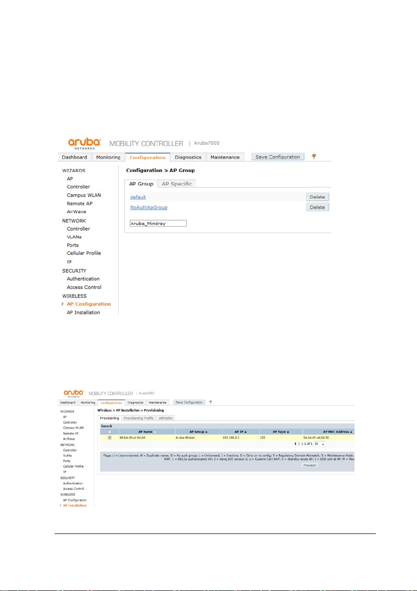
1. Choose Configuration>Wireless>AP Configuration>AP Group>New,The
configuration page is displayed. Input Aruba_Mindray in the box, and click the
Add. Perform the following configuration on the page, as shown below.
2. Choose Configuration>Wireless>AP Installation>Provision, The configuration
page is displayed. Select the used AP, Perform the following configuration on
the page, as shown below.
BeneVision TM80 Telemetry Monitor Service Manual 3-39
Page 62
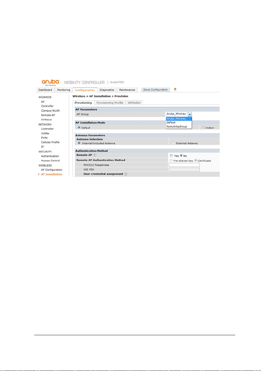
3. Click Provision, The configuration page is displayed. Perform the following
configuration on the page:
AP Group=Aruba_Mindray
The figure below shows the specific configuration.
4. Click Apply and reboot, and Save Configuration.
3-40 BeneVision TM80 Telemetry Monitor Service Manual
Page 63
3.4.3.2 Virtual AP setting
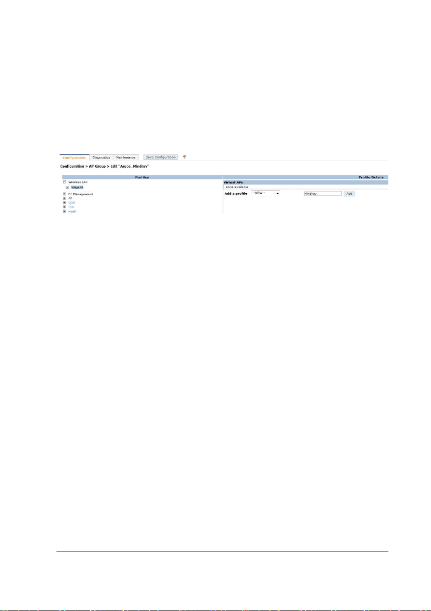
1. Choose Configuration>Wireless>AP
Configuration>APGroup>Aruba_Mindray>Wireless LAN>Virtual AP, input
Mindray in the box, and click the Add. The figure below shows the specific
configuration.
2. Choose Configuration>Wireless>AP Configuration>AP
Group>Aruba_Mindray>Wireless LAN>Virtual AP>Mindray, Perform the
following configuration on the page:
Virtual AP enable=enable
VLAN=VLAN ID (1)
Forward mode=tunnel
Allowed band=all
Steering Mode=prefer-5 ghz
Drop Broadcast and Unknown multicast=Disable
The figure below shows the specific configuration.
BeneVision TM80 Telemetry Monitor Service Manual 3-41
Page 64
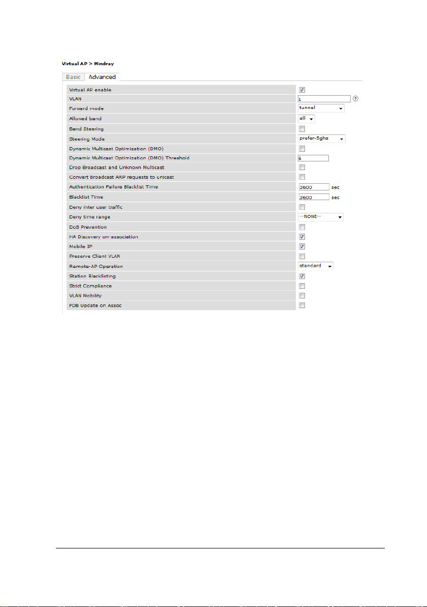
3. Click Apply and reboot, and Save Configuration
4. Choose Configuration>Wireless>AP Configuration>Wireless LAN>Virtual
AP>Mindray>SSID, Perform the following configuration on the Advanced page:
SSID Enable=Enable
ESSID=Mindray
Encryption=wpa2-psk-aes
PSK AES Key=12345678
DTIM interval=1 beacon periods
802.11a basic Rates=6/12/24
802.11a Transmit Rates=ALL
802.11b basic Rates=1/2/5.5/11
802.11b Transmit Rates=ALL
WPA Passphrase=12345678
3-42 BeneVision TM80 Telemetry Monitor Service Manual
Page 65

The figure below shows the specific configuration.
5. Click Apply and reboot, and Save Configuration
3.4.3.3 RF Management setting
This section describes configuration of 802.11a/n. Because the configuration option
of 802.11b/g/n is similar to this configuration, this configuration is not described in
detail here.
1. Choose Configuration>Wireless>AP Configuration>RF
Management>802.11a radio, Perform the following configuration on the
Advanced page:
Radio enable=enable
Mode=ap-mode
Channel=20Mhz
Spectrum Load Balancing=disable
Beacon Period=100msec
BeneVision TM80 Telemetry Monitor Service Manual 3-43
Page 66
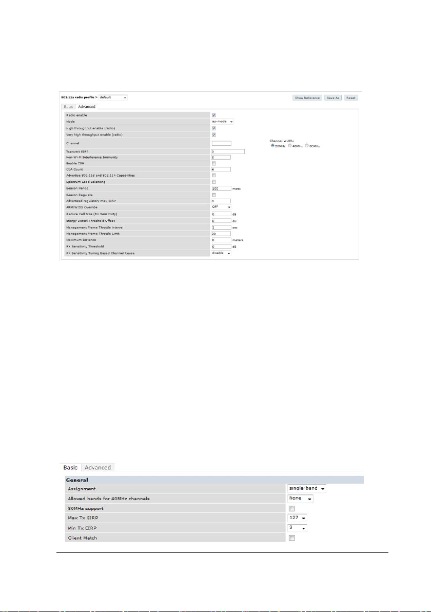
The figure below shows the specific configuration.
2. Click Apply and reboot, and Save Configuration
3. Choose Configuration>Wireless>AP Configuration>RF
Management>802.11a radio>Adaptive Radio Management, Perform the
following configuration on the Basic page:
Assignment=single-band
Allowed bands for 40Mhz channels=None
80Mhz support=disable
Max Tx EIRP=127
Min Tx EIRP=3
Client Match=disable
The figure below shows the specific configuration.
3-44 BeneVision TM80 Telemetry Monitor Service Manual
Page 67
4. Click Apply and reboot, and Save Configuration
3.4.3.4 AP setting
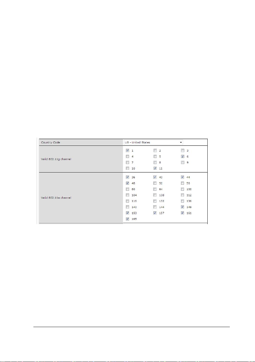
1. Choose Configuration>Wireless>AP Configuration>RF
Management>AP >Ethernet interface 4 port configuration>Regulatory Domain.
Perform the following configuration on the Basic page:
Country code=US
Valid 802.11g Channel=1/6/11
Valid 802.11a Channel=36~48 and 149~165
The figure below shows the specific configuration.
2. Click Apply and reboot, and Save Configuration
3.4.4 Network Setting
1. Choose Configuration-IP-IP interface-edit. Perform the following
configuration on the page.
IP Version=IPv4
DHCP Helper Addresses=192.168.0.50(The DHCP server's IP)
Enable IGMP=enable
BeneVision TM80 Telemetry Monitor Service Manual 3-45
Page 68
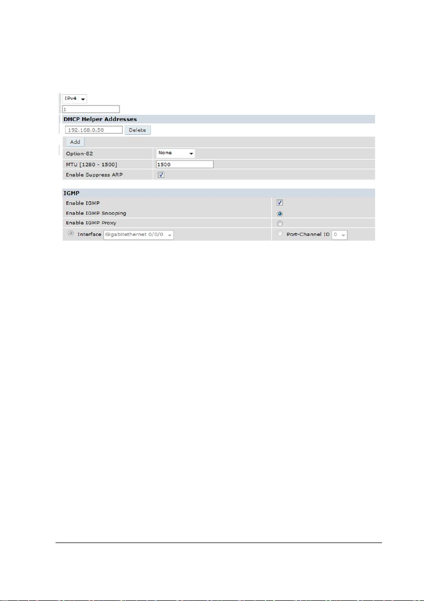
Enable IGMP Snooping=enable
The figure below shows the specific configuration.
2. Click Apply and reboot, and Save Configuration
3.5 Configuration of Netgear Network Devices
This section describes how to configure Netgear APs to meet wireless networking
requirements of Mindray monitors. The model recommended by Mindray is
WNDAP350. Because the IT infrastructures of different hospitals are different, below
configuration is only for your reference. You need to modify the configuration
according to your hospital IT department.
3-46 BeneVision TM80 Telemetry Monitor Service Manual
Page 69
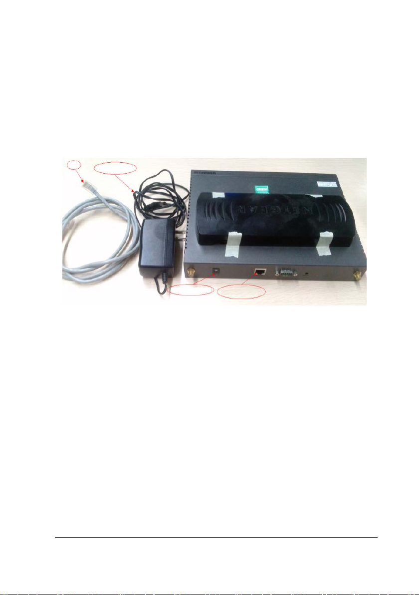
Network
cable
WNDAP350
power cable
WNDAP350
power interface
WNDAP35 network
interface
3.5.1 Preparation
3.5.1.1 Tools and Resources
WNDAP350 to be configured and power cable of WNDAP350
One network cable
One PC
Hardware to be prepared
3.5.1.2 Login
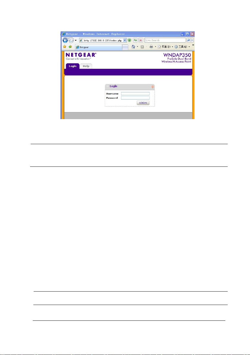
1. Set the IPv4 address of the PC to 192.168.0.1 and the subnet mask to
255.255.255.0 and connect the network port of the PC to the network
port of the WNDAP350 by using a network cable.
2. Open the IE, enter the default IP address of WNDAP35, namely
BeneVision TM80 Telemetry Monitor Service Manual 3-47
192.168.0.237, default user name admin, and passcode passcode, and
click LOGIN, as shown below.
Page 70
Note
After the AP setting is changed, click APPLY in the lower right corner so
that the setting can take effect.
3.5.2 Setting Single AP
3.5.2.1 System Settings
On the page, set the country where the network is built and time.
Country Setting
1. Choose Configuration→System→Basic→General. The configuration
page is displayed.
2. Perform the following configuration on the page.
Country/Region=United State
NOTE
Select a country according to the country where the network is built.
3-48 BeneVision TM80 Telemetry Monitor Service Manual
Page 71
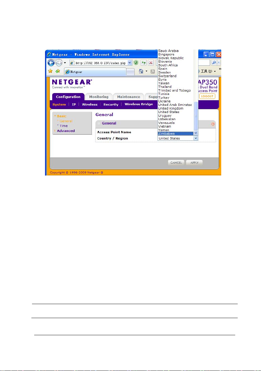
The figure below shows the specific configuration.
3. Click APP LY in the lower right corner to save the setting.
Time Settings
1. Choose Configuration→System→Basic→Time. The configuration page
is displayed.
2. Perform the following configuration on the page.
Time Zone=USA-Pacific
NTP Client=Enable
Use Custom NTP Server=Enable
NOTE
Select a time zone according to the country where the network is built.
BeneVision TM80 Telemetry Monitor Service Manual 3-49
Page 72
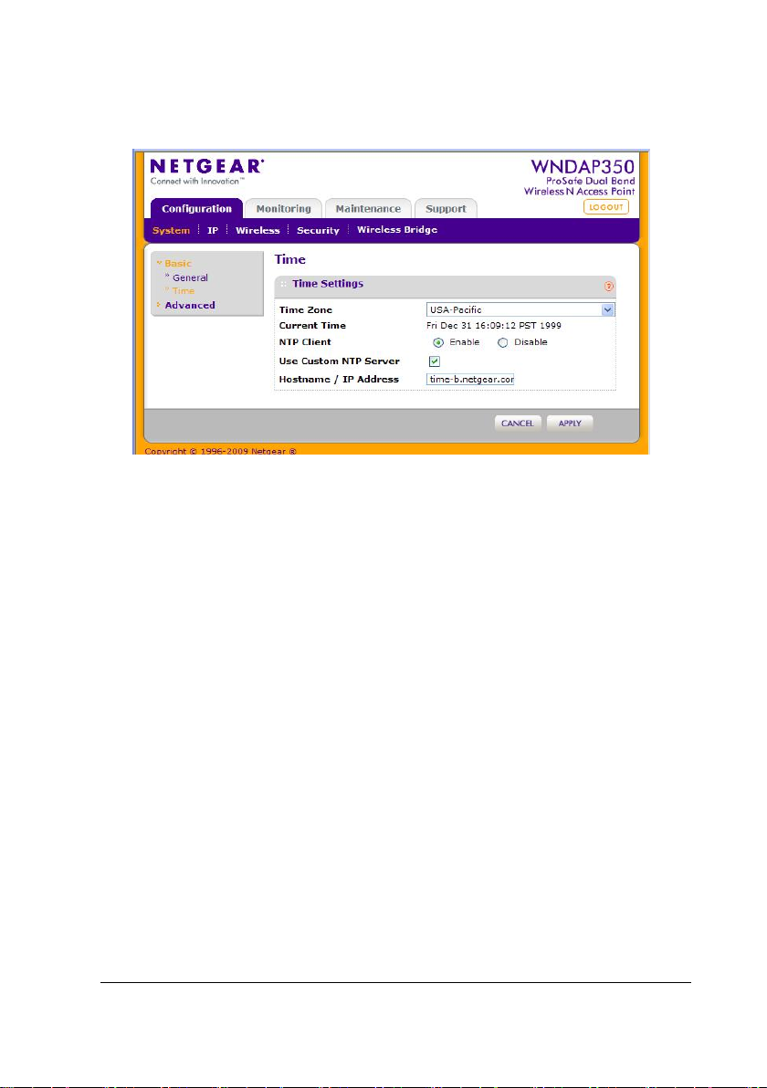
The figure below shows the specific configuration.
3. Click APP LY in the lower right corner to save the setting.
3.5.2.2 IP Settings
Setting AP’s IP
1. Choose Configuration→IP→IP Settings. The configuration page is
displayed.
2. Perform the following configuration on the page.
DHCP Client=Disable
IP Address=192.168.0.237
IP Subnet Mask=255.255.255.0
3-50 BeneVision TM80 Telemetry Monitor Service Manual
Page 73
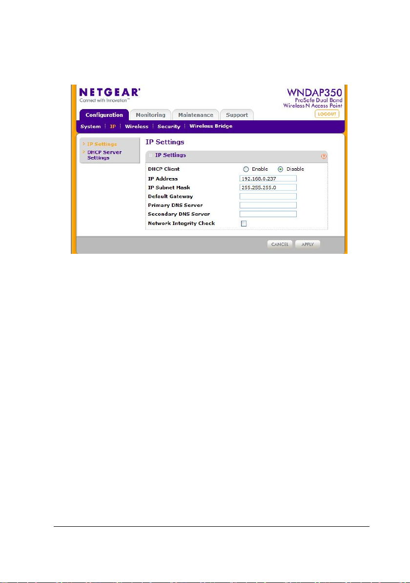
The figure below shows the specific configuration screen.
3. Click APP LY in the lower right corner to save the setting.
Setting IP of a Wi-Fi Device
Connect devices to the AP, use the AP as the DHCP server, and assign an IP address.
1. Choose Configuration→IP→DHCP Server Settings. The configuration
page is displayed.
2. Perform the following configuration on the page.
DHCP Server=Enable
DHCP Server VLAN ID=1
Starting IP Address=196.76.0.2
Ending IP Address=196.76.0.100
Subnet Mask=255.255.255.0
Gateway IP Address=196.76.0.254
BeneVision TM80 Telemetry Monitor Service Manual 3-51
Page 74
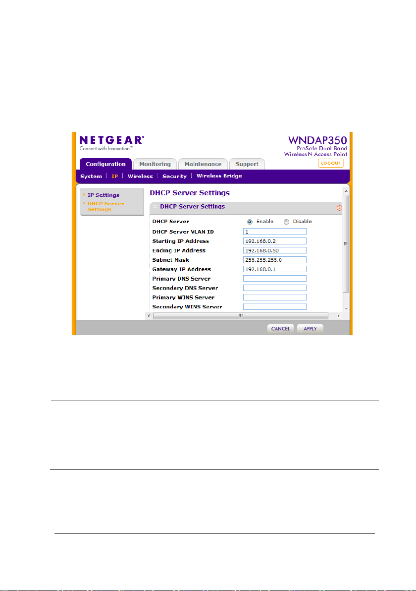
The figure below shows the specific configuration. Please note that the IPs of below
picture is different. You need to modify the DHCP setting according to hospital IT
department. However, please make sure the TM80 and BeneVision CMS can
communicate with each other.
3. Click APP LY in the lower right corner to save the setting.
NOTE
To establish a Wi-Fi network consisting of multiple APs, do not use the APs
as the DHCP server. Set a dedicated DHCP server in the wired network and
make the IP addresses of APs in the same network segment as the IP
addresses provided by the DHCP server.
3-52 BeneVision TM80 Telemetry Monitor Service Manual
Page 75
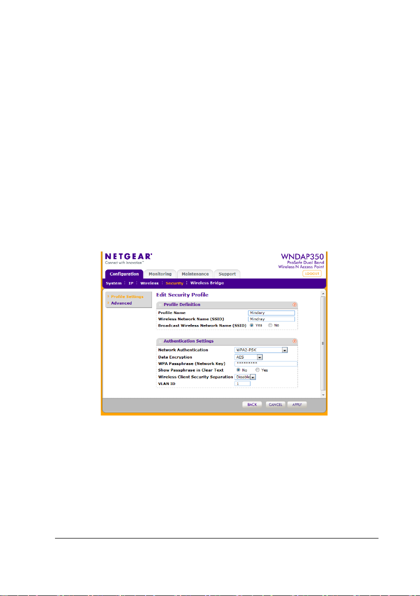
1. Click the circle on the left and click EDIT. On the configuration page,
perform the following configuration:
Network Authentication=WPA2-PSK
Data Encryption=AES
For the Network Key, please set it according to hospital IT. And you
need to input this key in TM80 menu.
Show Passphrase in clear Text=No
Wireless Customer Security Separation=Disable
VLAN ID=1
The figure below shows the specific configuration.
2. Click APP LY in the lower right corner to save the setting.
BeneVision TM80 Telemetry Monitor Service Manual 3-53
Page 76
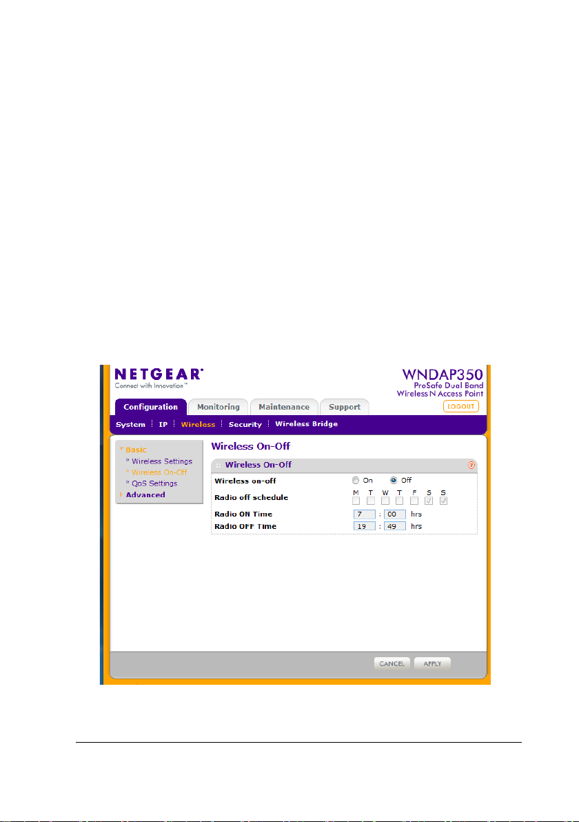
3.5.3 Wireless Settings (5G)
This section describes configuration of 802.11a/na. Because the configuration
option of 802.11b/g/ng is similar to this configuration,so it is not detailed here.
3.5.3.1 Wireless On-Off
1. Choose Configuration→Wireless→Basic→Wireless On-Off. The
configuration page is displayed.
2. Perform the following configuration on the page.
Wireless On-Off=Off
The figure below shows the specific configuration.
3. Click APP LY in the lower right corner to save the setting.
3-54 BeneVision TM80 Telemetry Monitor Service Manual
Page 77
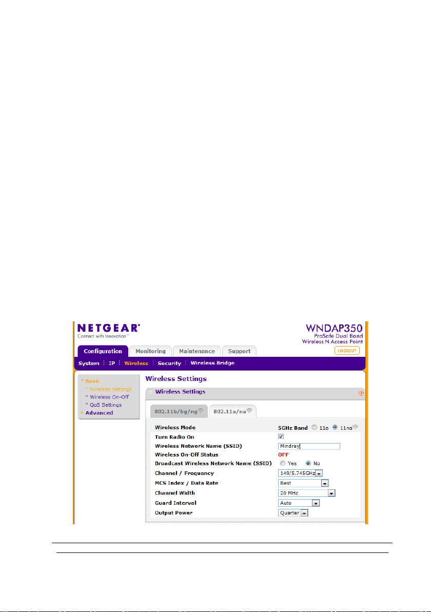
3.5.3.2 Wireless Settings
1. Choose Configuration→Wireless→Basic→Wireless Settings→802.11a/na.
2. On the configuration page, perform the following configuration:
Wireless Mode=11na
Turn Radio on=enable
Wireless Network Name(SSID)=Mindray. You can modify this SSID
according to hospital IT. After you change this name, please also
modify the TM80 SSID setting.
Broadcast Wireless Network Name(SSID)=Yes
Channel/Frequency=149/5.745G Hz . Yo u need to set the channel
according to the Wi-Fi survey result.
Output Power=Quarter
The figure below shows the specific configuration.
BeneVision TM80 Telemetry Monitor Service Manual 3-55
Page 78
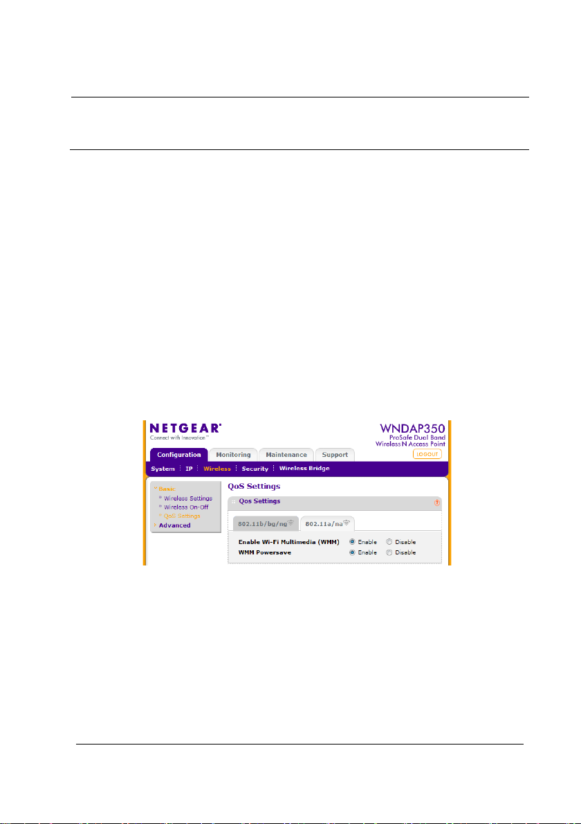
NOTE
According to the field survey data based on wireless survey tool, select the
minimum channel as a fixed channel.
3. Click APP LY in the lower right corner to save the setting.
3.5.3.3 QoS Setting (5G)
1. Choose Configuration→Wireless→Basic→QoS Settings. The
configuration page is displayed.
2. Perform the following configuration on the page.
Enable Wi-Fi Multimedia (WMM)=Enable
WMM Powersave=Enable
The figure below shows the specific configuration.
3. Click APP LY in the lower right corner to save the setting.
3.5.3.4 Security Settings (5G)
3. Choose Configuration→Security→Profile Settings→802.11a/na. On
the configuration page, click the box to enable the SSID, as shown below.
3-56 BeneVision TM80 Telemetry Monitor Service Manual
Page 79
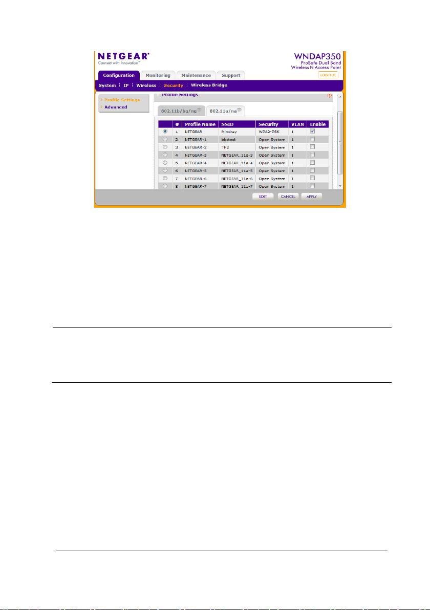
3.5.4 Setting Multiple APs
In the multi-AP setting, export the configuration file of a configured AP and import
the configuration file to APs to be configured.
NOTE
In the single-AP setting, the channel of the AP is allocated automatically. In
the multi-AP setting, manually fix a channel and ensure that adjacent
channels use non-overlapped channels.
3.5.4.1 Exporting a Configuration File
1. Choose Configuration→Maintenance→Upgrade→Backup Settings.
2. On the page for exporting configuration files, click BACKUP and export
the configuration file to a local directory, as shown below.
BeneVision TM80 Telemetry Monitor Service Manual 3-57
Page 80
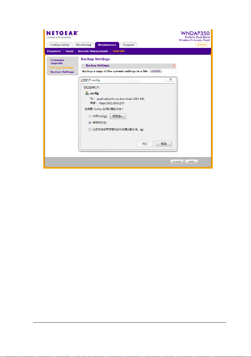
3-58 BeneVision TM80 Telemetry Monitor Service Manual
Page 81
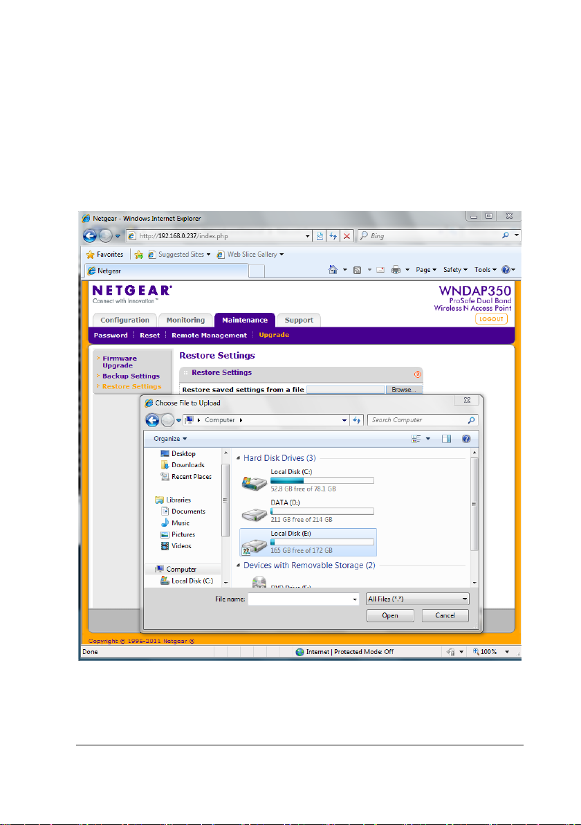
3.5.4.2 Importing a Configuration File
1. Choose Configuration→Maintenance→Upgrade→Restore Settings.
2. On the page for importing configuration files, click Browse, select a local
configuration file, and import it to the APs to be configured, as shown
below.
3. Click APP LY .
BeneVision TM80 Telemetry Monitor Service Manual 3-59
Page 82

3.6 Network Deployment Planning
3.6.1 Tools and Resources
Laptop computer, where Windows 7 or operating system of a later version is
installed and wireless network card is equipped. wireless network card‘s RSSI
dynamic range should be at least 45dB(e.g the highest value is -45dBm,the
lowest value is -90dBm).
Wireless network survey tool, we suggest to use professional survey tool such as
tamograph, Wirelessmon or other professional network survey tool.
TM80 main unit
Customer TM80 coverage plan
Tes t A Ps
Professional network engineer
NOTE
The personnel who implement the Wi-Fi site survey and network
deployment should be well trained about Wi-Fi. If you are not professional
network engineer, please ask some third party for help.
3.6.2 Environmental Survey
Mindray personnel meet with hospital IT, biomedical engineer and clinicians to
agree on network plan and clinical workflow requirements. The network plan should
include coverage, network topology, channel planning, and device model initially
selected.
3-60 BeneVision TM80 Telemetry Monitor Service Manual
Page 83

3.6.2.1 Environment Confirmation
First obtain the following information:
The layout and current pipe distribution map of the floor
coverage requirements
Number estimation of potential wireless terminal users
Then pre-plan bandwidth allocation and location distribution of main devices.
Finally, conduct a site survey. Site survey covers internal decoration structure of the
building (floor area, floor height, wall and ceiling materials, and areas to be covered),
and location where APs can be mounted.
Preparations before field test
Ask the customer to provide the site floor plan, schematic diagrams of floors and
floor height and collect building design drawings and official documents, so as
to get ware of the power supply for rooms and structure foundation (for
example, metal fire path, wall, doors, and passageway).
Ask the customer to provide the schematic diagram of wireless coverage
requirements.
Ask the customer to determine whether all areas need redundancy coverage or
which areas need redundancy coverage.
Ask the customer to provide personnel who are familiar with site conditions so as
to ask them questions about coverage, site layout, available installation points,
and channel planning and estimate the number of potential Wi-Fi devices
under each AP with them (a maximum of 16 devices are recommended for
each AP).
BeneVision TM80 Telemetry Monitor Service Manual 3-61
Page 84

ground
product
and floor
impact on wireless signal than old gypsum)
Synthetic
Low
Office partition wall
Site test and report
1. Check that the surrounding environment and placement of devices
during the test are consistent with those actually in use.
2. Learn distribution of Wi-Fi devices and other 2.4G products in the wireless
scope.
3. According to the site environment, initially determine the rough
installation locations of APs, find the cleanest channel by using Wireless
network survey tool, for example, channel 11 is relatively cleaner, open
the test AP, and set the channel to channel 11. Use the Wireless network
survey tool to test wireless coverage and ensure that the test can be
passed in the expected coverage of the test AP.
Go to the next expected AP installation location, perform the test again, and record
the results.
Field personnel must ensure that no blind spot exists in the required coverage and
that co-channel interference does not exceed the limit.
3.6.2.2 Preliminary Network Deployment Design
Cabling rules:
The figure below shows the degree of attenuation of various materials for radio
wave.
Barrier
Open
Wooden
Gypsum Low
3-62 BeneVision TM80 Telemetry Monitor Service Manual
Degree of
attenuation
No Cafeteria and courtyard
Low
Example
Interior wall, office partition wall, door
Interior wall (new gypsum has greater
Page 85

material
brick
Asbestos
Low
Ceiling
Glass
Low
Colorless window
glass
colored glass
body
Water
Medium
Damp wood, glass jar and organism
Brick
Medium
Damp wood, glass jar and organism
Marble
Medium
Interior wall, outer wall and ground
product
Paper
High
A roll or pile of paper
beam
glass
plating
ventilating device
Barrier
Degree of
attenuation
Example
Coal cinder
Metal net in
Metal
Human
Ceramic
Low Interior wall and outer wall
Medium Door and partition wall
Low Colored window
Medium Large group of people
High Ceramic tile, ceiling and ground
Concrete High
Bullet-proof
Silver
High Safety shed
Very high Mirror
Metal Very high
Ground, outer wall and load-bearing
Office table, office partition wall,
concrete, elevator, file cabinet and
1. The maximum indoor transmission distance of wifi is about 50m. In
practice, the distance of distinct vision is recommended to be 25m to
guarantee coverage. If a brick wall blocks the way, the recommended
distance should be divided by 2; if two brick walls block the way, the
recommended distance should be divided by 2 again. If a load bearing wall
blocks the way, the transmission distance would be greatly reduced. For
one load bearing wall, the transmission distance would be divided by 4.
BeneVision TM80 Telemetry Monitor Service Manual 3-63
Page 86
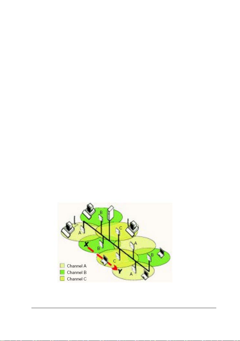
2. After completing cabling construction, draw the AP cabling diagram to
facilitate system operation and maintenance in the future.
3. Initially select locations of APs according to the actual scenario and
requirements and then make adjustment through field measurement.
Follow the rules: Ensure that all areas can be covered and try to reduce the
number of needed APs.
4. Channels occupied by coverage areas of APs should comply with certain
specifications. APs in nearby coverage areas cannot use the same channel;
otherwise, co-channel interference would be caused during signal
transmission of APs. Take 2.4G band as example, to utilize band resources
to the maximum extent, the most common method is to select three
non-overlapped channels (channels 1, 6, and 11) as the operating band of
the whole system. the channels1, 6, and 11 are mutually adjacent and
partially overlapped (as shown in the figure below) so as to eliminate blind
spots and avoid co-channel interference while obtaining the largest
coverage area.
3-64 BeneVision TM80 Telemetry Monitor Service Manual
Page 87
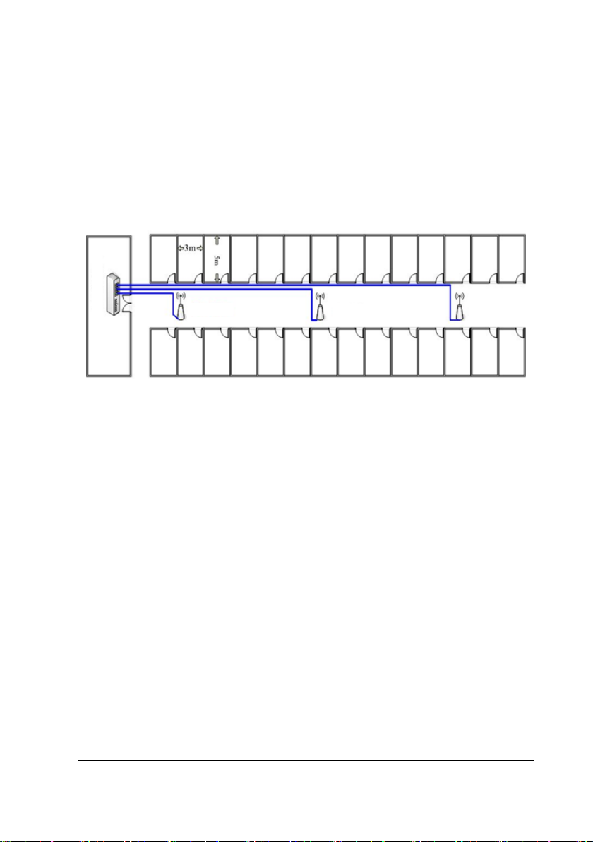
Switch for CMS
Ward
AP AP AP
5. APs that implement wireless roaming network must use the same network
name (SSID) and IP address in the same network segment. Otherwise,
wireless customers cannot implement the roaming function.
Examples of AP layout
3.7 Network Deployment Implementation
This section describes the approximate process of network deployment, which is
performed by professional third party and adjusted according to actual conditions.
3.7.1 Preparations before Equipment Installation
1. According to the site test report, determine locations and install the
network cable and power supply cable.
2. Test the network cable and power supply cable for connectivity.
3. Prepare installation tools: mounting brackets needed by APs and
mechanical tools.
4. Ask the customer to provide climbing equipment (if needed) and
available time for operation (daytime, night and specific time).
BeneVision TM80 Telemetry Monitor Service Manual 3-65
Page 88

3.7.2 Roaming Consideration
The following operation is recommended to guarantee the roaming performance:
Plan possible roaming areas, optimize AP coverage, and reduce the number of AP
handovers on the roaming path.
Donot make tm80 roam across different IP subnet.
Ensure that the same SSID is set for APs in the coverage area.
Ensure that all APs on the roaming path are under the control of the same WLC.
Try not to use enterprise-class encryption, which results in longer roaming time.
3.7.3 Services Provided During and After Installation
1. During installation, perform the following tests for wireless devices
(including APs and laptop computers) at the same time: network
connectivity, security performance, and software operation.
2. Make sure that the configurations of APs meet requirements of this
document.
3. According to requirements of the contract, provide wireless device
settings and maintenance training.
4. Provide technical consulting service after installation to ensure that
equipment is used properly.
3-66 BeneVision TM80 Telemetry Monitor Service Manual
Page 89

3.8 Network Verification
3.8.1 Tools and Resources
Laptop computer, where Windows 7 or operating system of a later version is
installed and wireless network card is equipped. We recommended laptop
configured with Intel Centrino Wireless-N adapter. If your laptop is configured
with some other wireless adapter, please make sure the adapter has a high
degree of accuracy.
Wireless network survey tool, we suggest to use professional survey tool such as
tamograph, Wirelessmon or other professional network survey tool.
TM80 main unit
TM80 coverage plan
Professional network engineer
NOTE
The personnel who implement the Wi-Fi network survey should be well
trained about Wi-Fi. If professional network engineers are not available,
please ask some third party for help.
3.8.2 Wi-Fi Signal Calibration
Before a Wireless network survey tool (running on laptop computer) is used to test
network coverage, calibrates the RSSI of wireless network survey tool with TM80.
Keep the TM80 and Wireless network survey tool close. The distance between them
is not greater than 30cm and the distance from human body is above 50 cm. Move
the TM80 and Wireless network survey tool at the same time (maintain the previous
distance). When the TM80 reads the following RSSI values: -50dBm,-60dBm, -70dBm
and -80dBm, record the RSSI values read by Wireless network survey tool.
BeneVision TM80 Telemetry Monitor Service Manual 3-67
Page 90

Then calibrate the RSSI of Wireless network survey tool to TM80 when do site survey
(the RSSI of TM80 is the benchmark to wireless coverage).
3.8.3 Confirm Network Feasibility
Wireless coverage and AP capability and compatibility are decided by infrastructure
of network, it can’t be modified easily. If the network does not meet the
requirements before TM80 is installed, network dropping-off may happen easily
after installation.
Verify these requirements to confirm network feasibility. For verification contents
and method, see3.11.2Environmental Survey Table.
Site survey: To confirm coverage, perform coverage test in the asserted areas
including toilet ,corridor, stairs and other place whereTM80 may be used. The
service person can finish the wireless network survey via third-party
professional survey tool such as tamograph, Wirelessmon or other
professionalnetwork survey tool. The RSSI of TM80 is the benchmarkto wireless
coverage. So it’s necessary to calibrates the RSSI of the wireless network survey
tool with TM80. The site survey must be carried out when the network is
operational and other devices are wirelessly connected.During the test, the
WLAN SSID broadcasting function must be enabled for TM80.
RF environment simulation: Some customers may carry out theoretic design for
deployment of APs by using a simulation tool or deploying analysis tool. The
work can accelerate network deployment but air interface detection cannot be
omitted. This is because the location, power, and channel of an AP may be
adjusted during actual deployment.
3-68 BeneVision TM80 Telemetry Monitor Service Manual
Page 91

3.8.4 Network Verification Process
Network Verification aims to confirm coverage, connectivity, service ports, and
network bandwidth. In addition, other configuration requirements of the TM80
need to be confirmed with the IT Dept. of the hospital. For the Verification content
and method see 3.11.3Network Acceptance Table.
This part is completed through two ways: First the hospital completes items
requiring self-check of the hospital’s IT Dept., as indicated in the Network
Verification Table. Then customer service personnel or authorized party confirms
items on site and finally completes the Network Acceptance Table. If any item is
found incompliant during network Verification test, adjustment should be made
before the TM80 is installed.
A laptop computer needs to be used to simulate the TM80 main unit, so as to test
coverage, connectivity, service ports, and network bandwidth. During the test, the
SSID broadcast needs to be enabled to ensure that the SSID can be scanned.
BeneVision TM80 Telemetry Monitor Service Manual 3-69
Page 92

Address Setup
to High.
cate
Main
Set the region
For details, refer to3.9.4.3WiFi
3.9 Configuring WLAN Settings of TM80
This table lists the items that need to be configured to make proper operation of the
TM80.
Item Description Remarks
Main
Menu->Maintenance
-> Network->IP
Set static IP
address or DHCP
For details, please refer to
BeneVision TM80 Telemetry Monitor
Operator’s Manual
Main Menu ->
Maintenance->
Network-> WALN
Setup
Main Menu ->
Maintenance
->Network->
Connect CMS
Main Menu ->
Maintenance->
Network-> Wireless
Setup
Main Menu ->
Maintenance->
Network->EAPCertifi
Configure SSID,
passcode, EAP, etc.
Configure how to
connect to the CMS.
Select to use 2.4G
band or 5G band
Manage CA
certificates and user
certificates
For details, please refer to
BeneVision TM80 Telemetry Monitor
Operator’s Manual
For details, please refer to
BeneVision TM80 Telemetry Monitor
Operator’s Manual
If CMS and TM80 are not in
the same subnet, multicast TTL
should be greater than 1.
It is recommended to set QoS
5G band is highly
recommended.
If 2.4G is selected, the TM80
can only roam between 2.4G
channels, but never goes to 5G
channels. Vice verse.
For more details, refer to
3.9.55G Band Channels.
For details, please refer to
BeneVision TM80 Telemetry Monitor
Operator’s Manual.
Main
Menu->Maintenance
->Service-> WLAN
test->Roaming Test
3-70 BeneVision TM80 Telemetry Monitor Service Manual
Configure roam
parameters that will
affect TM80’s roaming
performance
For details, refer to 3.9.4.4
Roaming Test.
Page 93

Regulatory domain
WPA2 with AES+TKIP
WPA2 with TKIP.
Item Description Remarks
Menu->Maintenance
->Service->WLAN
where the TM80 will be
used
Regulation Domain.
test->WIFI
NOTE
After changing the setting in Main Menu ->Maintenance->Service, you
should reboot TM80 to make sure that TM80’s settings take effect.
3.9.1 WLAN Setup
1. Press to enter the main menu.
2. Tap Maintenance→ enter the required passcode→ tap Network→ tap
WLAN Setup.
3. Enter a network name for Network Name.
4. Set Security Type to WPA/WPA2 EAP or WPA/WPA2 PSK.
Some important information for security types:
Security Type of TM80 Compatible Security Type of AP Remarks
BeneVision TM80 Telemetry Monitor Service Manual 3-71
WPA/WPA2 PSK
WPA/WPA2 EAP
WPA with AES
WPA with TKIP
WPA with AES+TKIP
WPA2 with AES
WPA2 with AES
WPA2 with AES+TKIP
Do not use
WPA2 with TKIP
Do not use
WPA.
Do not use
Page 94

MSCHAPV2
GTC
TLS Y N Y Y
Y
3.9.2 EAP Setup
1. Press to enter the main menu.
2. Tap Maintenance→ enter the required passcode→ tap Network→ tap
WLAN Setup.
3. Enter a network name for Network Name.
4. Set Security Type to WPA/WPA2 EAP.
5. Select the desired EAP method. Then items related to this EAP method will be
displayed. Different items need to be configured for corresponding EAP
method.
This table shows correspondence between EAP method and Configuration Items.
EAP type Identity Anonymity Passcode CA
Certificate
PEAP-
PEAP-
Note: Y means Yes, and configuration is required; N means No and configuration is
not required; O means optional.
Configuration items are defined as below:
Authentication(Phase2 Auth):After selecting PEAP as the EAP method, you
need to select MSCHAPV2or GTC as the PEAP inner method.
Identification: i.e. user identity. It is the user name in the AD, LDAP or local user
management on the RADIUS server.
Anonymous : This item does not impact the authentication process. It is used to
hide the real name(Identity).
Network Passcode: The passcode for the Identity.
CA Certificate: Select the desired CA certificate.
Y O Y O N
Y O Y O N
User
Certificate
3-72 BeneVision TM80 Telemetry Monitor Service Manual
Page 95

User Certificate: Select the desired user certificate.
CAUTION
TM80 supportsEAP only when using 5G band.When change band from 5G
to 2.4G, WLAN settings must be re-configured to use WPA/WPA2 PSK.
NOTE
TM80 supports three type of RADIUS server : Freeradius, acs, and
windows server.
3.9.3 EAP Certificate Management
You can import up to 10 certificates from a USB drive or delete certificates from
theTM80.
NOTE
After restoring factory defaults,all certificates will be
deletedautomatically by TM80.
3.9.3.1 Preparing Certificates
The following RADIUS Server is validated by Mindray:
Cisco ACS
FreeRadius
Network Policy Service( in Windows Server 2008 R2 and Windows Server 2012
R2)
Currently, X.509.v3 is a mainstream certificate standard. It has two main coding
formats: DER and PEM. Certificates in DER format are mainly suffixed with”.cer”, “.der”,
BeneVision TM80 Telemetry Monitor Service Manual 3-73
Page 96
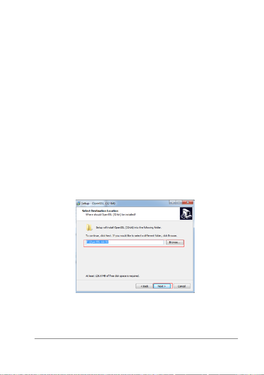
and “.crt”. Certificates in PEM format are mainly suffixed with “.pem”.
The TM80 only supports certificates in PEM format. If you need to use certificates in
other formats, you need to convert the certificates before importing them into the
TM80. The openssl tool (version 1.0.2c or later) is recommended for the conversion,
and you can get the setup file on internet conveniently.
openssl tool preparation consists of two steps: installing an openssl tool and
configuring environment variables.
Installing an openssl tool
You can install the openssl tool as default. Win32OpenSSL-1_0_2c.exe is taken as an
example.
1. Click the setup file to start.
2. Click Next to continue.
3. Select "I accept.." and click Next to continue.
4. Select the install path and click Next to continue
5. Click Next to continue until setup is finished.
Configure environment variables
You must add the install path (in Step4 above) to the computer's environment
3-74 BeneVision TM80 Telemetry Monitor Service Manual
Page 97

variables. After this, you can use openssl in the command line interface as shown
below:
Check your certificates’ suffix. If it's not "pem" you should select the appropriate
command to convert.
Steps to converting CA Certs:
Before start converting, we need to know the format of the CA Cert. It could be DER
or Base64.
The DER cert is binary format, and the Base64 cert is text format. So we can figure
out the format by open the cert with notepad. If the content displayed in the
notepad contains "BEGIN CERTIFICATE", then the CA Cert is in Base64 format,
otherwise it is in DER format.
Command for converting the DER CA Cert to PEM cert
openssl x509 -inform der -in [ca].cer -out [ca].pem
Command for converting the Base64 CA Cert to PEM cert
openssl x509 -inform PEM -in [ca].cer -out [ca].pem
NOTE
The file size of the CA Cert should less than 2KB
BeneVision TM80 Telemetry Monitor Service Manual 3-75
Page 98

Steps for converting User Cert
If the User Cert is .pfx file, then use the following steps for converting:
1. Get the file only containing cert
openssl pkcs12 -in [user cert].pfx -clcerts -nokeys -out [user cert].pem
2. Get the file only containing key
openssl pkcs12 -in [user cert].pfx -nocerts -out [user cert key in pkcs12].pem
3. Convert the key from pkcs12 to pkcs8
openssl pkcs8 -topk8 -inform PEM -in [user cert key in pkcs12].pem -outform PEM
-nocrypt -out [user cert key in pkcs8].pem
4. Merge the cert and key to one file
1) Open the [user cert].pem with notepad, only keep the lines between "-----BEGIN
CERTIFICATE-----" and "-----END CERTIFICATE-----" and delete the other lines.
3-76 BeneVision TM80 Telemetry Monitor Service Manual
Page 99
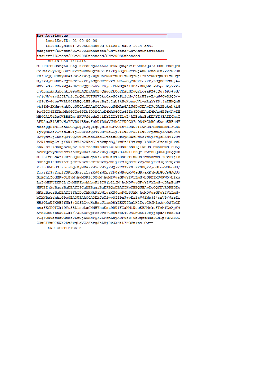
2) Open the [user cert key in pkcs8].pem with notepad, and copy the content of the
key file and paste it to the end of the cert file. And the merged user cert file contains
the following two parts:
Cert parts: lines between "-----BEGIN CERTIFICATE----- "and "-----END
CERTIFICATE-----"
Key parts: lines between "-----BEGIN PRIVATE KEY-----" and "-----END PRIVATE
KEY-----"
BeneVision TM80 Telemetry Monitor Service Manual 3-77
Page 100
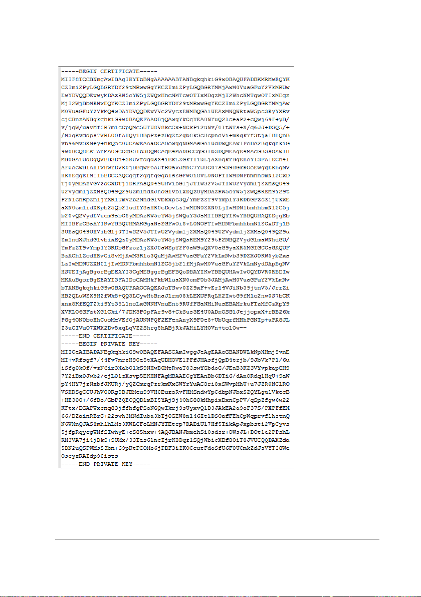
The cert file is shown below:
3-78 BeneVision TM80 Telemetry Monitor Service Manual
 Loading...