

Page 1

Ultrasonic Transducer
Operator’s Manual
Page 2

Page 3

Contents
Contents ..................................................................................................................................i
1 Overview ...................................................................................................................... 1-1
1.1 Safety Classification ............................................................................................................. 1-1
1.2 Applications .......................................................................................................................... 1-1
1.3 Acoustic Power ..................................................................................................................... 1-1
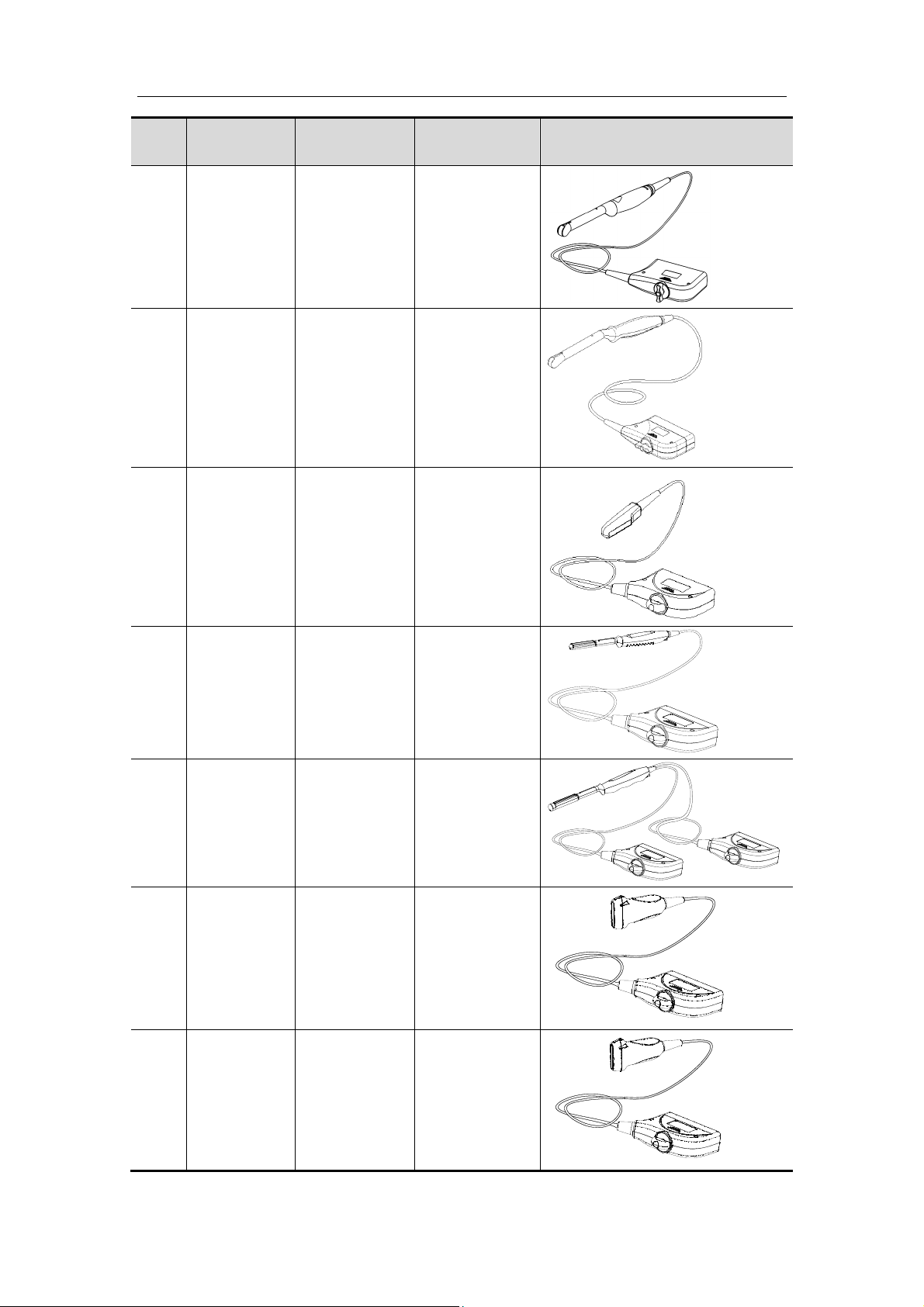
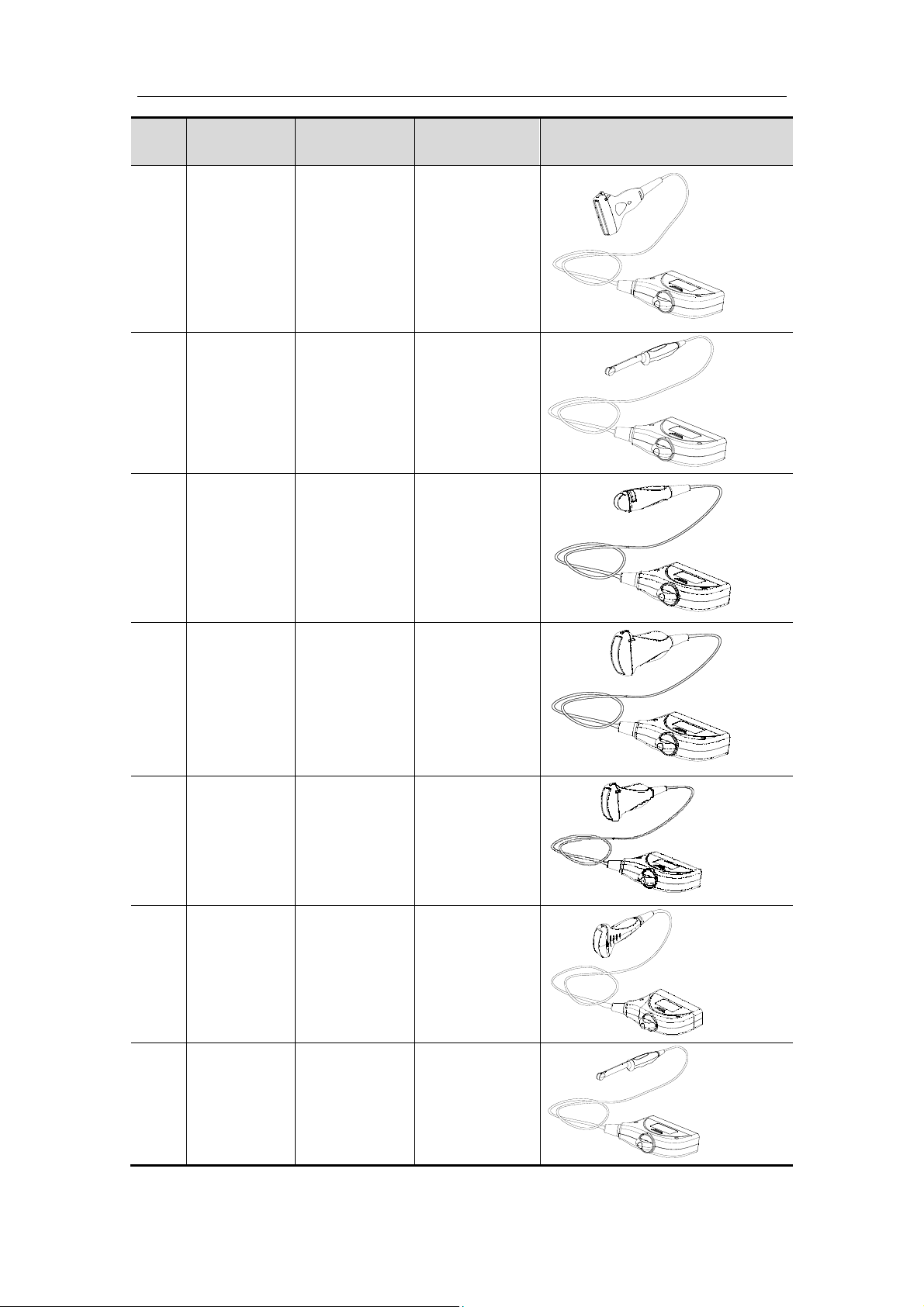
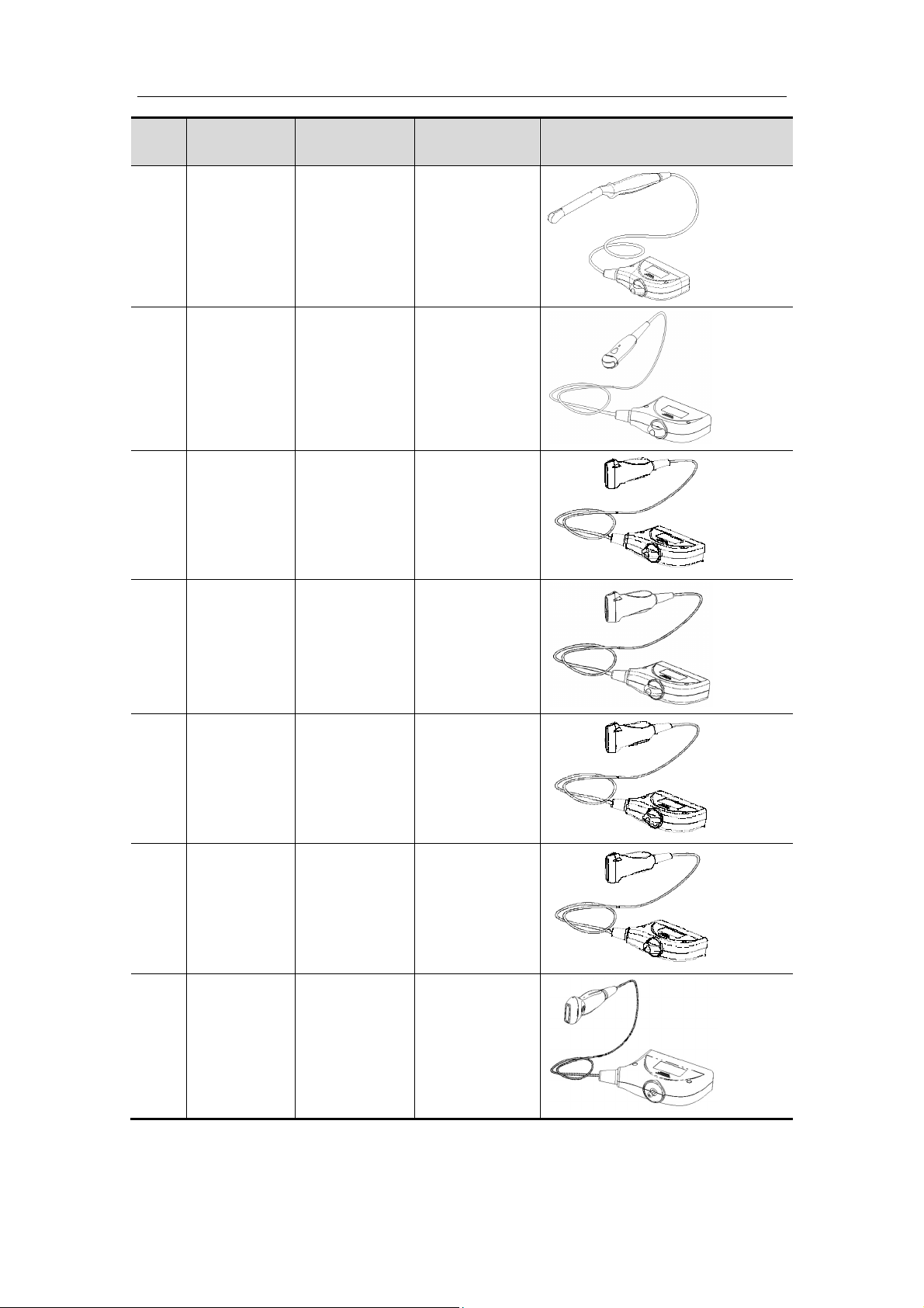
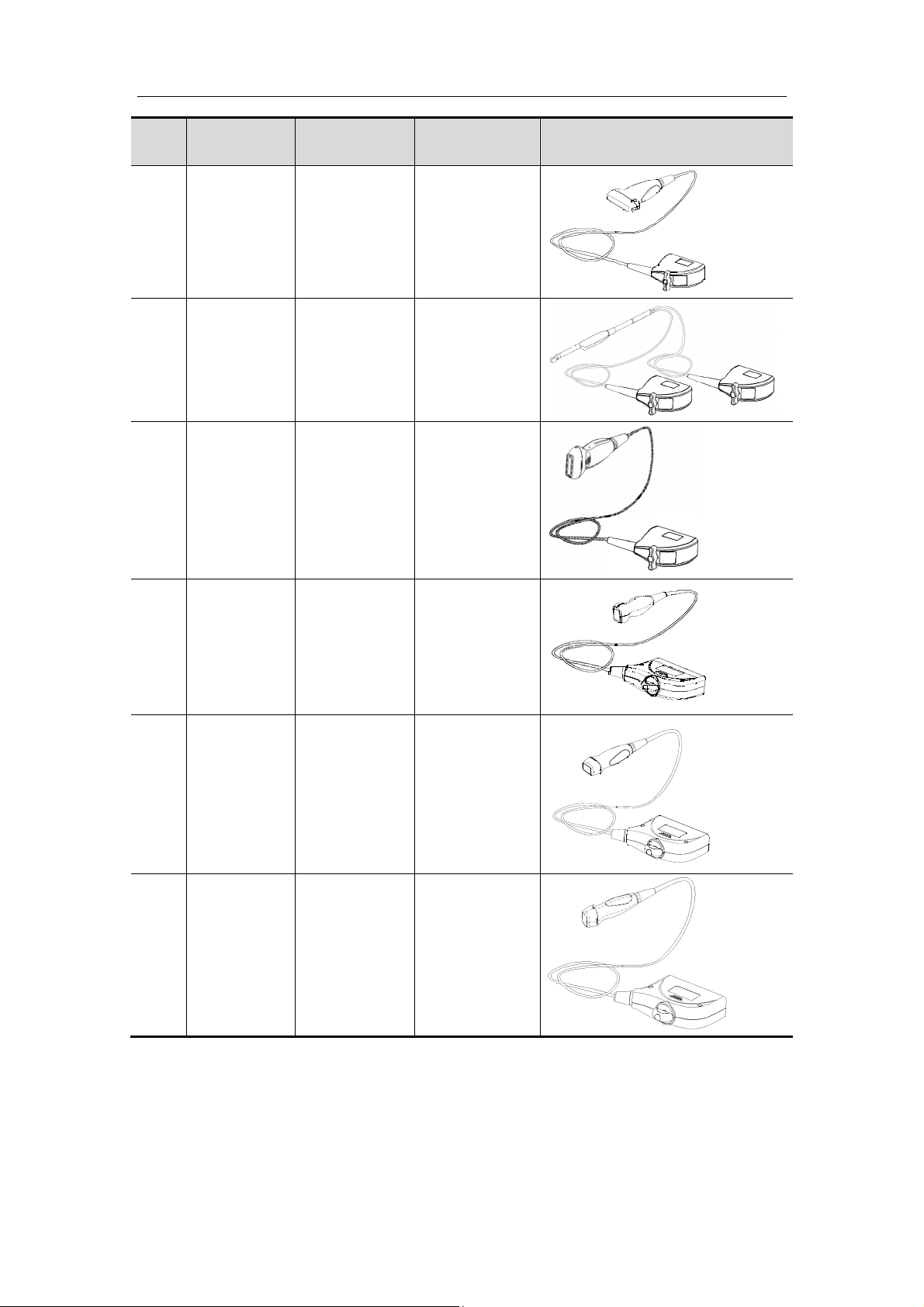
1.4 Transducer/Needle-guided Bracket Model ........................................................................... 1-1
1.5 Composition ....................................................................................................................... 1-19
1.6 Procedures for Operating the Transducer ......................................................................... 1-24
2 Connecting the Transducer to the System ............................................................... 2-1
2.1 Connecting and Disconnecting the Transducer ................................................................... 2-1
3 Inspection Before and After Use ............................................................................... 3-1
3.1 Check the External Appearance of the Transducer ............................................................. 3-1
3.2 Cleaning the Transducer ...................................................................................................... 3-1
3.3 Checking after Turning on the System ................................................................................. 3-1
4 Operating Procedures ................................................................................................ 4-1
4.1 Orientation of the Ultrasound Image and the Transducer Head .......................................... 4-1
4.2 Utilizing the Transducer Sheath ........................................................................................... 4-2
4.3 When the Immersion Method is Used .................................................................................. 4-3
4.4 Examinations ........................................................................................................................ 4-7
4.5 After Examinations ............................................................................................................... 4-7
5 Cleaning and Disinfection .......................................................................................... 5-1
5.1 Cleaning ............................................................................................................................... 5-1
5.2 High Level Disinfections ....................................................................................................... 5-2
5.3 Sterilization ........................................................................................................................... 5-5
6 Needle-guided Bracket and Biopsy .......................................................................... 6-1
7 Storage and Transportation ....................................................................................... 7-1
8 Specifications ............................................................................................................. 8-1
i
Page 4

Page 5
© 2010-2016 Shenzhen Mindray Bio-Medical Electronics Co., Ltd. All rights Reserved.
For this Operator’s Manual, the issue date is 2016-04.
Intellectual Property Statement
SHENZHEN MINDRAY BIO-MEDICAL ELECTRONICS CO., LTD. (hereinafter called
Mindray) owns the intellectual property rights to this Mindray product and this manual.
This manual may refer to information protected by copyright or patents and does not
convey any license under the patent rights or copyright of Mindray, or of others.
Mindray intends to maintain the contents of this manual as confidential information.
Disclosure of the information in this manual in any manner whatsoever without the written
permission of Mindray is strictly forbidden.
Release, amendment, reproduction, distribution, rent
other derivative work of this manual in any manner whatsoever without the written
permission of Mindray is strictly forbidden.
, , , , , BeneView,
WATO, BeneHeart, are the trademarks, registered or otherwise, of Mindray in China
and other countries. All other trademarks that appear in this manual are used only for
informational or editorial purposes. They are the property of their respective owners.
al, adaptation, translation or any
Responsibility on the Manufacturer Party
Contents of this manual are subject to change without prior notice.
All information contained in this manual is believed to be correct. Mindray shall not be
liable for errors contained herein or for incidental or consequential damages in
connection with the furnishing, performance, or use of this manual.
Mindray is responsible for the effects on safety, reliability and performance of this product,
only if:
z all installation operations, expansions, changes, modifications and repairs of this
product are conducted by Mindray authorized personnel;
z the electrical installation of the relevant room complies with the applicable
national and local requirements; and
z the product is used in accordance with the instructions for use.
Note
This equipment must be operated by skilled/trained clinical professionals.
Warning
It is important for the hospital or organization that employs this equipment to carry out a
reasonable service/maintenance plan. Neglect of this may result in machine breakdown
or personal injury.
I
Page 6

Warranty
THIS WARRANTY IS EXCLUSIVE AND IS IN LIEU OF ALL OTHER WARRANTIES,
EXPRESSED OR IMPLIED, INCLUDING WARRANTIES OF MERCHANTABILITY OR
FITNESS FOR ANY PARTICULAR PURPOSE.
Exemptions
Mindray's obligation or liability under this warranty does not include any transportation or
other charges or liability for direct, indirect or consequential damages or delay resulting
from the improper use or application of the product or the use of parts or accessories not
approved by Mindray or repairs by people other than Mindray authorized personnel.
This warranty shall not extend to:
Malfunction or damage caused by improper use or man-made failure.
Malfunction or damage caused by unstable or out-of-range power input.
Malfunction or damage caused by force majeure such as fire and earthquake.
Malfunction or damage caused by improper operation or repair by unqualified
or unauthorized service people.
Malfunction of the instrument or part whose serial number is not legible
enough.
Others not caused by instrument or part itself.
II
Page 7

Company Contact
Manufacturer:
Shenzhen Mindray Bio-Medical Electronics Co., Ltd.
Address: Mindray Building, Keji 12th Road South, High-tech industrial
park, Nanshan, Shenzhen 518057,P.R.China
Website:
E-mail
www.mindray.com
Address:
Tel:
Fax:
EC-Representative: Shanghai International Holding Corp. GmbH(Europe)
Address: Eiffestraβe 80, Hamburg 20537, Germany
Tel: 0049-40-2513175
Fax: 0049-40-255726
Manufacturer: Mindray DS USA, Inc.
+86 755 81888998
+86 755 26582680
Address: 800 MacArthur Blvd.
Mahwah, NJ 07430-0619 USA
Tel: +1(201) 995-8000
Toll Free: +1 (800) 288-2121
Fax: +1 (800) 926-4275
III
Page 8

Important Information
Responsibility on customers:
1. The responsibility for maintenance and management of the product after delivery
resides with the customer who has purchased the product.
2. The warranty does not cover the following items, even during the warranty period:
(1) Damage or loss due to misuse or abuse.
(2) Damage or loss caused by Acts of God such as fires, earthquakes, floods,
lightning, etc.
(3) Damage or loss caused by failure to meet the specified conditions for this
system, such as inadequate power supply, improper installation or environmental
conditions.
(4) Damage or loss due to use of the system outside the region where the system
was originally sold.
(5) Damage or loss involving the system purchased from a source other than
Mindray or its authorized agents.
3. This equipment shall not be used by persons other than fully qualified and certified
medical personnel.
4. Do not make changes or modifications to the software or hardware of this product.
5. In no event shall MINDRAY be liable for problems, damage, or loss caused by
relocation, modification, or repair performed by personnel other than those
designated by MINDRAY.
6. The purpose of this system is to provide physicians with data for clinical diagnosis.
The responsibility for diagnostic procedures lies with the physicians involved.
MINDRAY shall not be liable for the results of diagnostic procedures.
7. MINDRAY shall not be liable for loss of data stored in the memory of this system
caused by operator error or accidents.
8. This manual contains Warnings regarding foreseeable potential dangers. Be alert at
all times to dangers other than those indicated. MINDRAY shall not be liable for
damage or loss that results from negligence or from ignoring the precautions and
operating instructions contained in this operator’s manual.
9. On the occasion of change of the administrator or manager for this system, be sure
to hand over this operator’s manual.
10. When disposing of this system, contact your MINDRAY Customer Service
Department or sales representative. Do not dispose of this system without consulting
MINDRAY Customer Service Department or sales representative first. MINDRAY
does not assume any responsibility for damage resulting from disposal of this system
without consulting MINDRAY.
IV
Page 9

Introduction
This operator’s manual describes the operating procedure for the transducers. To ensure
safe and correct operation of the transducer, read the operator’s manual carefully and
understand the transducers clearly before operation.
For the operating procedures for the ultrasonic diagnostic system and other devices,
please refer to the relevant manuals.
V
Page 10
Safety Precautions
Meaning of Signal Words
In this operator’s manual, DANGER, WARNING, CAUTION and
NOTE are signal words used to indicate safety and other important instructions. The
signal words and their meanings are defined as follows. Please understand their
meanings clearly before reading this manual.
Signal Word Meaning
DANGER
Indicates an imminentl
avoided, will result in death or serious injury.
y hazardous situation that, if not
WARNING
CAUTION
NOTE Indicates a potentially hazardous situation that, if not avoided, may
Indicates a potentially hazardous situation that, if not avoided,
could result in death or serious injury.
Indicates a potentially hazardous situation that, if not avoided,
may result in minor or moderate injury.
result in property damage.
Meaning of Safety Symbols
Symbol
General warning, caution, risk of danger.
Description
Safety Precautions
Please read the following precautions carefully to ensure the safety of the patient and the
operator when using this transducer.
DANGER:
WARNING:
DO NOT use flammable gasses, such as anesthetic gas or
hydrogen, or flammable liquids such as ethanol, near the
product, because there is danger of explosion.
1. Confirm that the transducer and cable are normal before
and after each examination. A defective transducer may
cause electric shock to the patient.
2. Do not subject the transducer to shock. A defective
transducer may cause electric shock to the patient.
VI
Page 11

3. Do not disassemble the transducer to avoid the possibility
of electric shock.
4. Never immerse the transducer connector into liquids such
as water or disinfectant because the connector is not
waterproof. Immersion may cause electric shock or
malfunction.
5. The ultrasonic transducer is only for use with the
specified ultrasonic diagnostic system. Please refer the
ultrasonic diagnostic system operation manual to select
the proper transducer.
6. A transducer sheath must be installed over the transducer
before performing examination.
7. Do not use an aftermarket probe other than those
specified by Mindray. The probes may damage the system
causing a profound failure, e.g. a fire in the worst case.
CAUTION:
1. When using the transducer, wear sterile gloves to prevent
infection.
2. Be sure to use ultrasound gel. Please use the ultrasound
gel compliant with the relevant local regulations.
3. In normal diagnostic ultrasound mode, there is no danger
of a low-temperature burn; however, keeping the
transducer on the same region of the patient for a long
time may cause such a burn.
4. Do not use the carrying case for storing the transducer. If
the carrying case is used for storage, it may become a
source of infection.
5. The transducer and accessories supplied with it are not
delivered disinfected or sterilized. Sterilization (or highlevel disinfect) before use is required.
6. It is required to practice ALARA when operating
ultrasound system. Minimize the acoustic power without
compromising the quality of images.
7. Disposable components are packaged sterile and are
single-use only. Do not use if integrity of packaging
violated or if expiration date has passed. Please use the
disposable components compliant with the relevant local
regulations.
8. Please use the disinfection or sterilization solution that
recommended in this operator’s manual, otherwise
Mindray will not be liable for damage caused by other
solutions. If you have any questions, please contact
Mindray Customer Service Department or sales
representative.
9. Do not use pre-lubricated condoms as a sheath.
Lubricant may not be compatible with the transducer
material and damage may result.
VII
Page 12

10. Transducer damage may be caused by inappropriate gel,
detergent or
cleanser:
Do not soak or saturate transducers with solutions
containing alcohol, bleach, ammonium chloride
compounds, acetone or formaldehyde.
Avoid contact with solutions or coupling gels containing
mineral oil or lanolin.
NOTE:
1. Read the following precautions to prevent the transducer from
malfunction.
z Before connecting or disconnecting the transducer, freeze or
turn off the ultrasonic diagnostic system.
z Clean and disinfect the transducer before and after each
examination.
2. Ambient conditions:
To prevent the transducer from being damaged, do not use it
where it will be exposed to:
z direct sunlight or X-rays
z sudden changes in temperature
z dust
z excessive vibration
z heat generators
Use the transducer under the specified ambient conditions, for
details; please refer to “8 Specifications”.
3. Repeated disinfection will eventually damage the transducer,
please check the transducer’s performance periodically.
VIII
Page 13
Labels
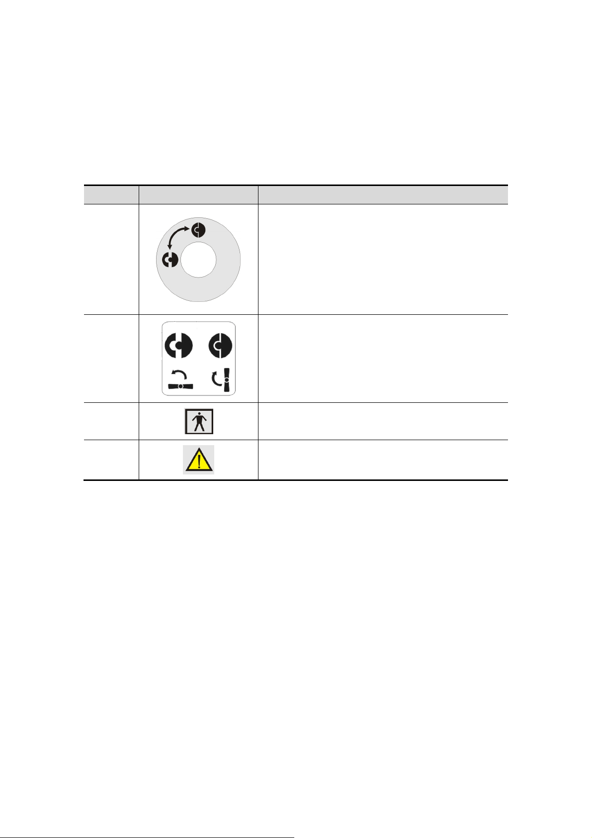
Various labels are attached to the device in order to call the user's attention.
This operator’s manual describes the safety precautions of operating the transducer.
Read the operator’s manual carefully before using the system.
Some labels are shown in the following.
No. Label Meaning
1
3
4
2
Indicates the direction of the lock handle. The top
symbol indicates the position of locked handle, the
left symbol indicates the position of the unlocked
handle.
This label is found on Doppler ultrasound system
transducers and on black and white ultrasound
128-element transducers.
Indicates the direction of the lock handle. The left
symbol indicates the position of the unlocked
status; the right symbol indicates the position of the
locked status. .
This label is found on black and white ultrasound
80-element transducers.
Type-BF applied part.
General warning sign.
IX
Page 14

Page 15
1 Overview
1.1 Safety Classification
Please refer to the safety classification information in the related operator’s manual for
the ultrasonic diagnostic system that matches with the transducer.
1.2 Applications
Please check the operator’s manual for the ultrasonic diagnostic system to check the
compatibility of the transducer.
For the intended use, please refer to the operator's manuals of the corresponding
diagnostic ultrasound system.
1.3 Acoustic Power
The effects of acoustic power on human tissue are currently under investigation.
Therefore, it is recommended that diagnostic ultrasound output power be set to the
lowest possible levels in accordance with the ALARA (As Low As Reasonably Achievable)
principle.
Please refer to the operator’s manual of the ultrasonic diagnostic system.
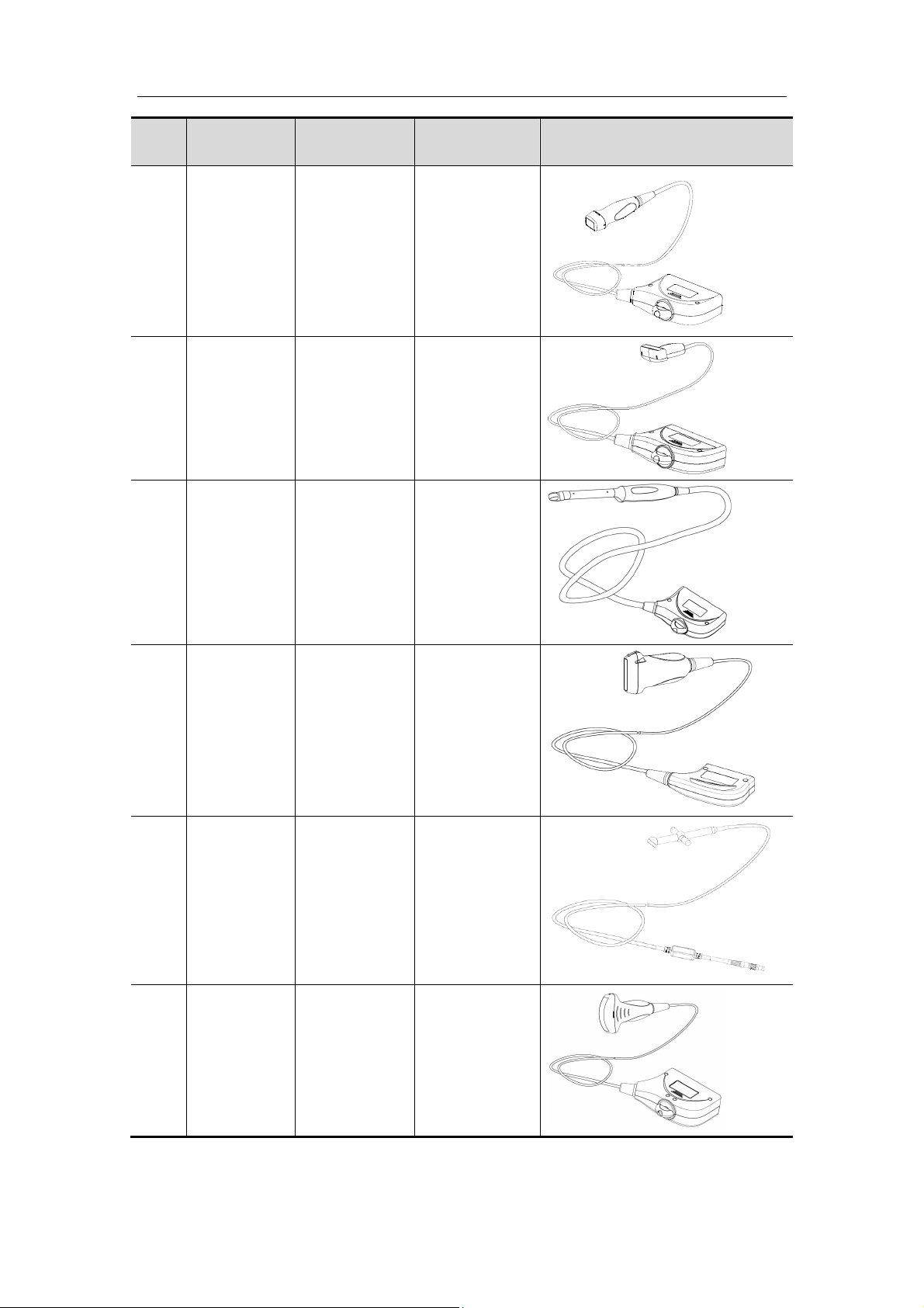
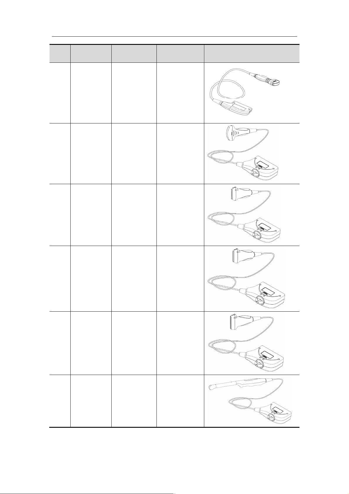
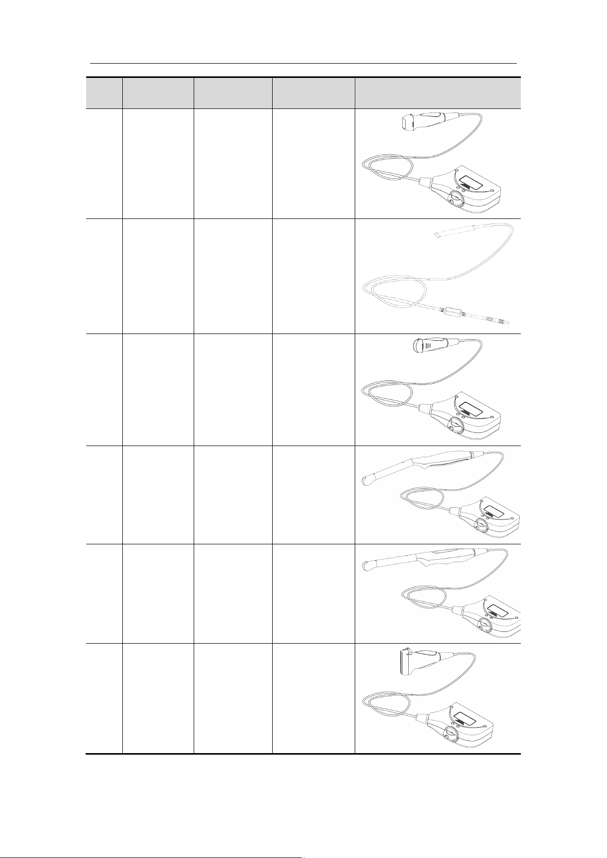
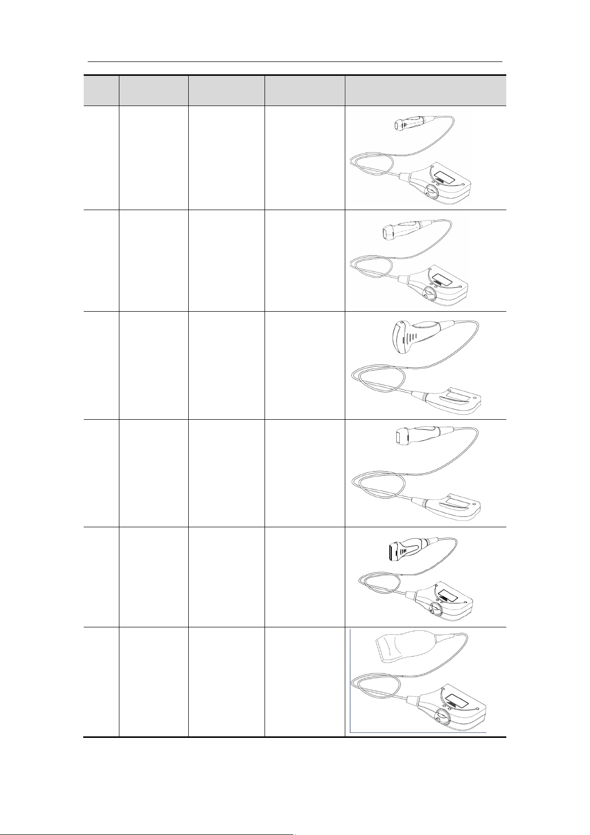
1.4 Transducer/Needle-guided Bracket
Model
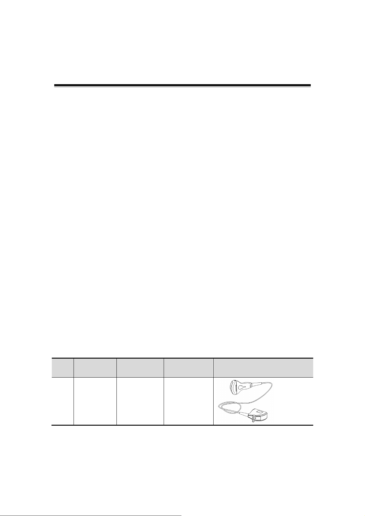
1.4.1 Transducer Model
No. Model Type
1. 35C50EB Convex Body surface
Applied
region
1-1
Illustration
Page 16
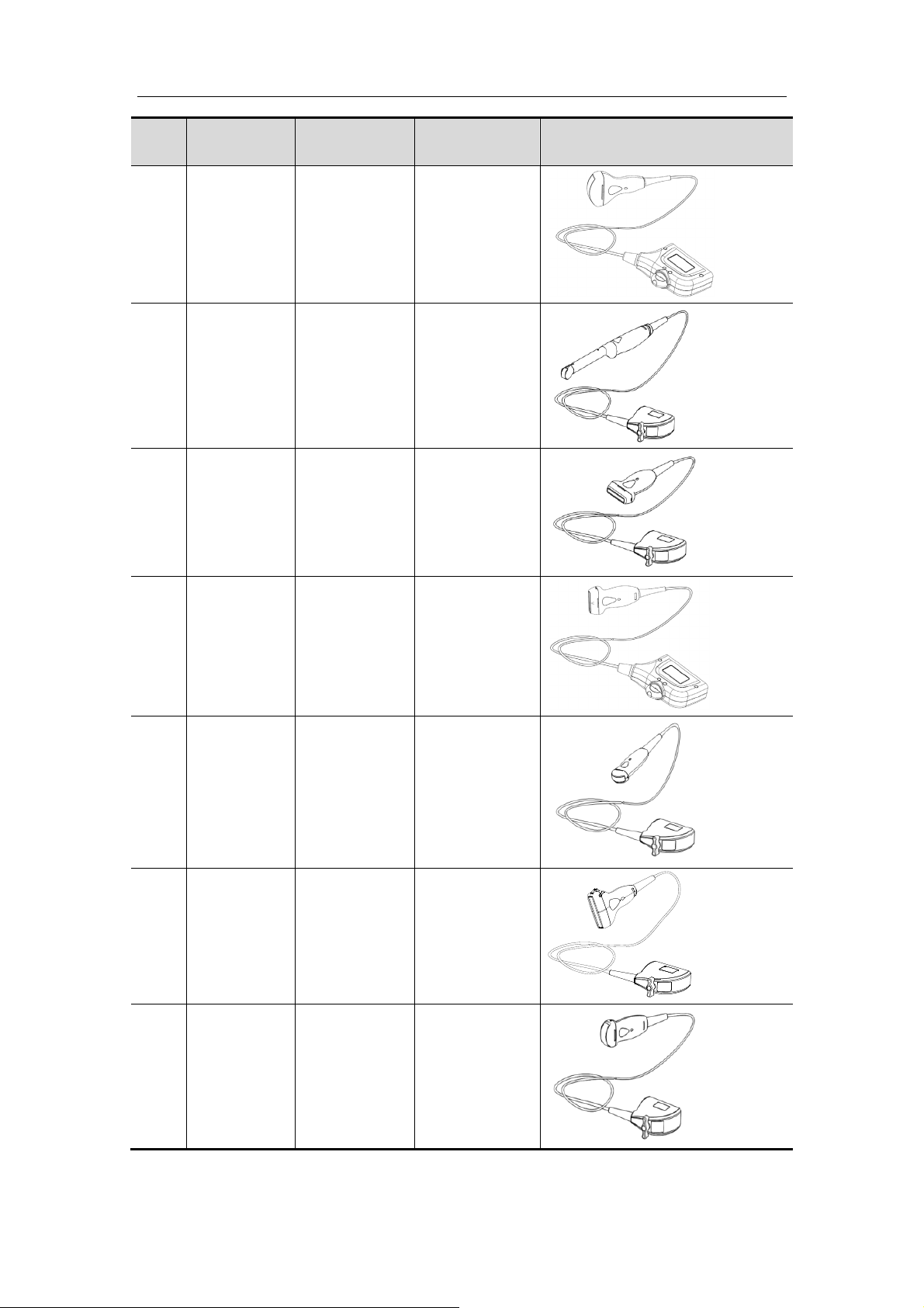
Overview
No. Model Type
2. 35C50P Convex Body surface
3. 65EC10EB
4. 75L3 8EB Linear Body surface
Convex
(intracavitary)
Applied
region
Transrectal,
transvaginal
Illustration
5. 75L38P Linear Body surface
6. 65C15EA Convex Body surface
7. 75L6 0EA Linear Body surface
8. 35C20EA Convex Body surface
1-2
Page 17
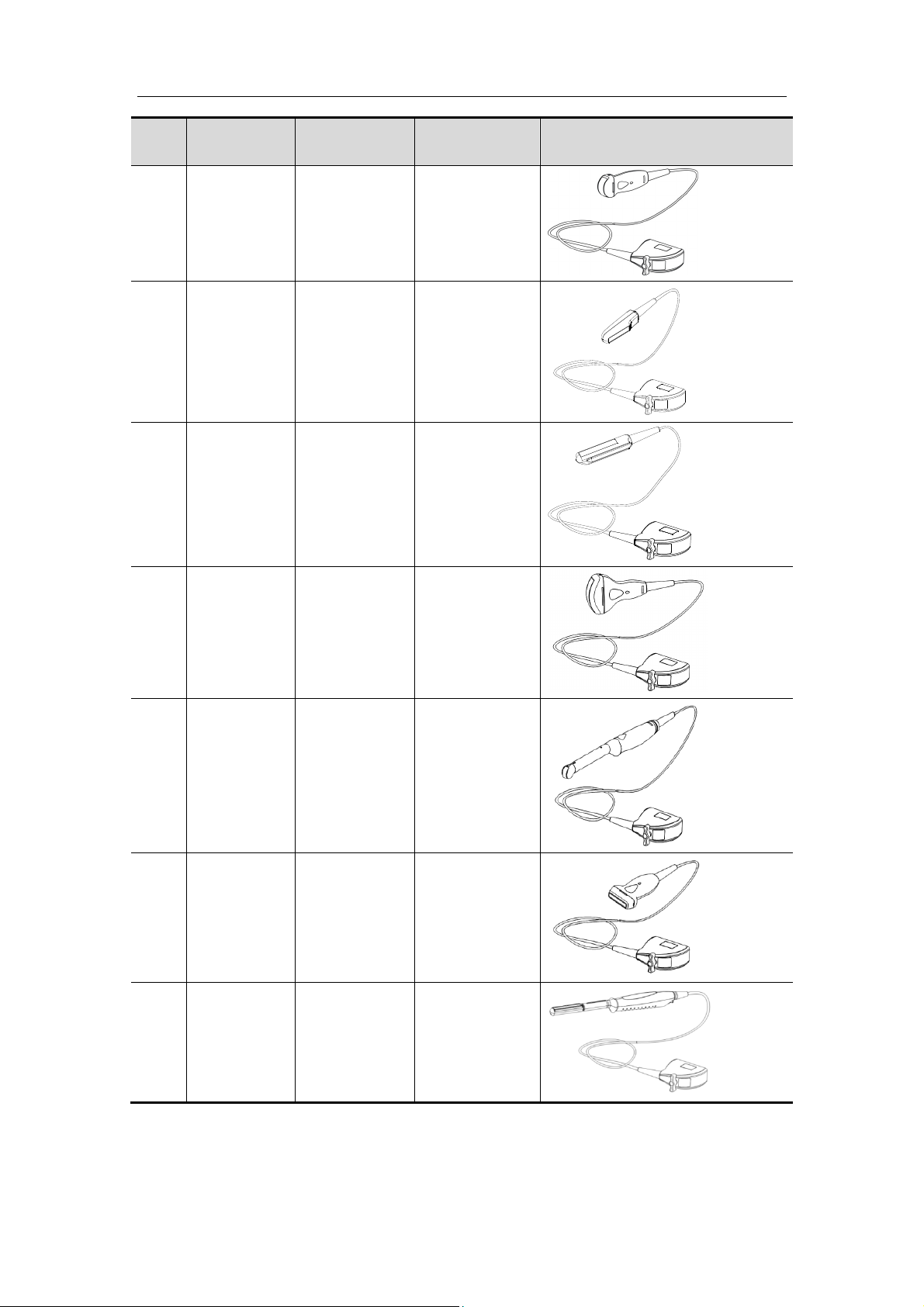
Overview
No. Model Type
Applied
region
9. 65C15EAV Convex Body surface
10. 75L50EAV Linear
11. 50 L60EAV Linear
Transrectal
Transrectal
Illustration
12. 35C50EA Convex Body surface
13. 65EC10EA
Convex
(intracavitary)
Transrectal,
transvaginal
14. 75L3 8EA Linear Body surface
15. 65EL60EA
Linear
transrectal)
(
Transrectal
1-3
Page 18
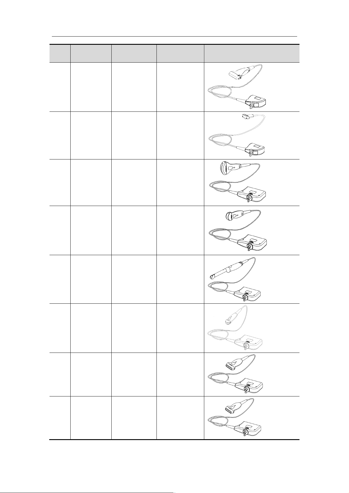
Overview
No. Model Type
16. 75L5 3EA Linear Body surface
17. 75LT38EA Linear Intraoperative
18. 35C50HA Convex Body surface
Applied
region
Illustration
19. 35C20HA Convex Body surface
20. 65EC10HA
21. 65C15HA Convex Body surface
22. 75L38HA Linear Body surface
Convex
(intracavitary)
Transrectal,
transvaginal
23. 75L38HB Linear Body surface
1-4
Page 19
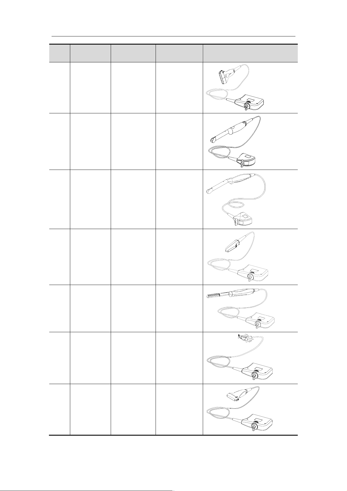
Overview
No. Model Type
Applied
region
24. 75L60HB Linear Body surface
25.
26.
65EC10EC
65EC10ED
Convex
(intracavitary)
Convex
(intracavitary)
Transvaginal
Transvaginal
Illustration
27.
28.
29.
65L50HAV
65EL66HA
75LT40HA
Linear Transrectal
Linear
(transrectal)
Transrectal
Linear Intraoperative
30.
75L53HA
Linear Body surface
1-5
Page 20
Overview
No. Model Type
31.
32.
33.
65EC10HC
65EC10HD
6LE5V/6LE5
Vs
Convex
(intracavitary)
Convex
(intracavitary)
Linear Transrectal
Applied
region
Transvaginal
Transvaginal
Illustration
6LE7/
34.
6LE7s/
Linear
(
transrectal)
Transrectal
6LE7P
35. 6LB7/6LB7s Biplanar Transrectal
36. 10L4/10L4s Linear Body surface
37. 7L4/7L 4s Linear Body surface
1-6
Page 21
Overview
No. Model Type
Applied
region
38. 7L6/7L 6s Linear Body surface
39.
6CV1/6CV1
s/6CV1P
Convex
(intracavitary)
Transrectal,
transvaginal
40. 3C1/3C1s Convex Body surface
Illustration
41. 3C5/3C5s Convex Body surface
42. 3C5A/3C5P Convex Body surface
43. C5-2/C5-2s Convex Body surface
44. V10-4/10-4s Convex Transvaginal
1-7
Page 22
Overview
No. Model Type
Applied
region
V10-4B/
45.
V10-4Bs/
Convex Transvaginal
V10-4BP
6C2/
46.
6C2s/
Convex Body surface
6C2P
47. 7L4A/7L4P Linear Body surface
Illustration
48.
49.
L11-4/L11-
4s
L12-4/L12-
4s
Linear Body surface
Linear Body surface
50. L7-3/L7-3s Linear Body surface
51.
L14-6/L14-
6s/L14-6P
Body surface
Linear
1-8
Page 23
Overview
No. Model Type
52.
53. 65EB10EA
7L5/7L5s
/7L5P
Linear
Bi-plane
(convex)
Body surface
Applied
region
Transrectal
54. 10L2 4EA Linear Body surface
Illustration
55.
56.
57.
2P2/
2P2s/
2P2P
P7-3/P7-
3s/P7-3E
P12-4/
P12-4s
Phased Body surface
Phased Body surface
Phased Body surface
1-9
Page 24
Overview
No. Model Type
Applied
region
58. P4-2/P4-2s Phased Body surface
59.
60.
7LT4/
7LT4s/
7LT4P
CB10-
4/CB10-4P/
CB10-4E
Linear
Bi-plane
(convex &
convex)
Intraoperation,
Body surface
Transrectal
Illustration
61. L14-6Ns Linear Body surface
62. CW2s Pencil probe Body surface
63. C5-2E Convex Body surface
1-10
Page 25
Overview
No. Model Type
64. C6-2Gs Convex Body surface
65. C7-3E Convex Body surface
66. L12-3E Linear Body surface
Applied
region
Illustration
67. L14-6NE Linear Body surface
L14-
68.
69.
6WE/L14-
6Ws
V11-3E/V11-
3
Linear Body surface
Convex Transvaginal
1-11
Page 26
Overview
No. Model Type
70. P4-2E Phased Body surface
71. CW5/CW5s Pencil probe Body surface
Applied
region
Illustration
72.
73.
74.
C11-3E/
C11-3s
V11-
3BE/V11-3B
V11-3WE/
V11-3Ws
Convex Body surface
Convex Transvaginal
Convex Transvaginal
75. L7-3E Linear Body surface
1-12
Page 27
Overview
No. Model Type
76.
77. P4-2NE Phased Body surface
78. C5-1s Convex Body surface
P10-
4E/P10-4s
Phased Body surface
Applied
region
Illustration
79.
80.
81.
SP5-
1s/SP5-1E
LM14-
6E/LM14-6s
L10-3E/L10-
3s
Phased Body surface
Linear Body surface
Linear Body surface
1-13
Page 28
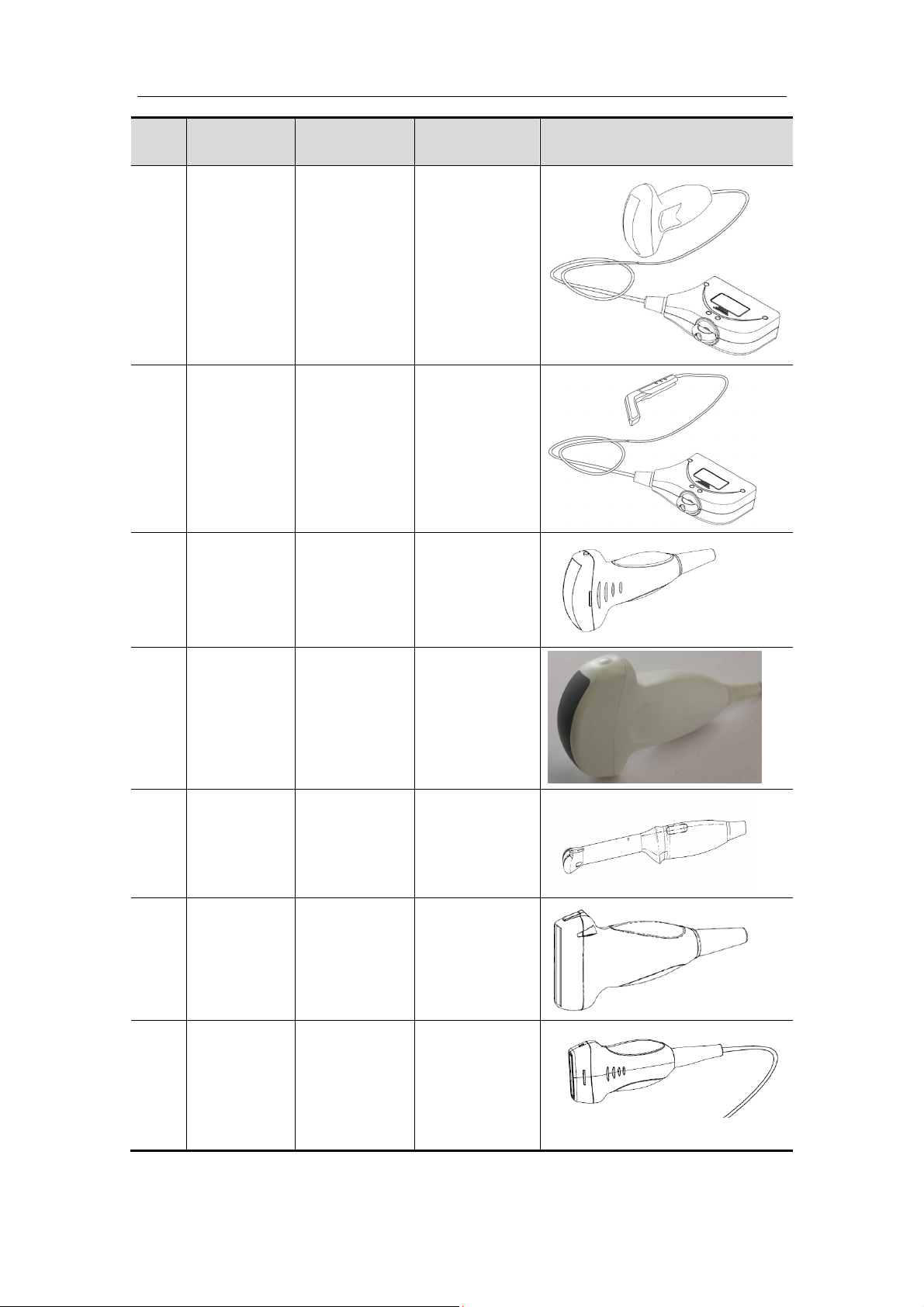
Overview
No. Model Type
Applied
region
82. SC5-1E Convex Body surface
L16-
83.
4HE/L16-
Linear Body surface
4Hs
Illustration
84.
85.
86.
87.
C5-1U
SC8-2U
V11-3HU
L14-6WU
Convex Body surface
Convex Body surface
Convex Transvaginal
Linear Body surface
88.
L11-3U
Linear Body surface
1-14
Page 29
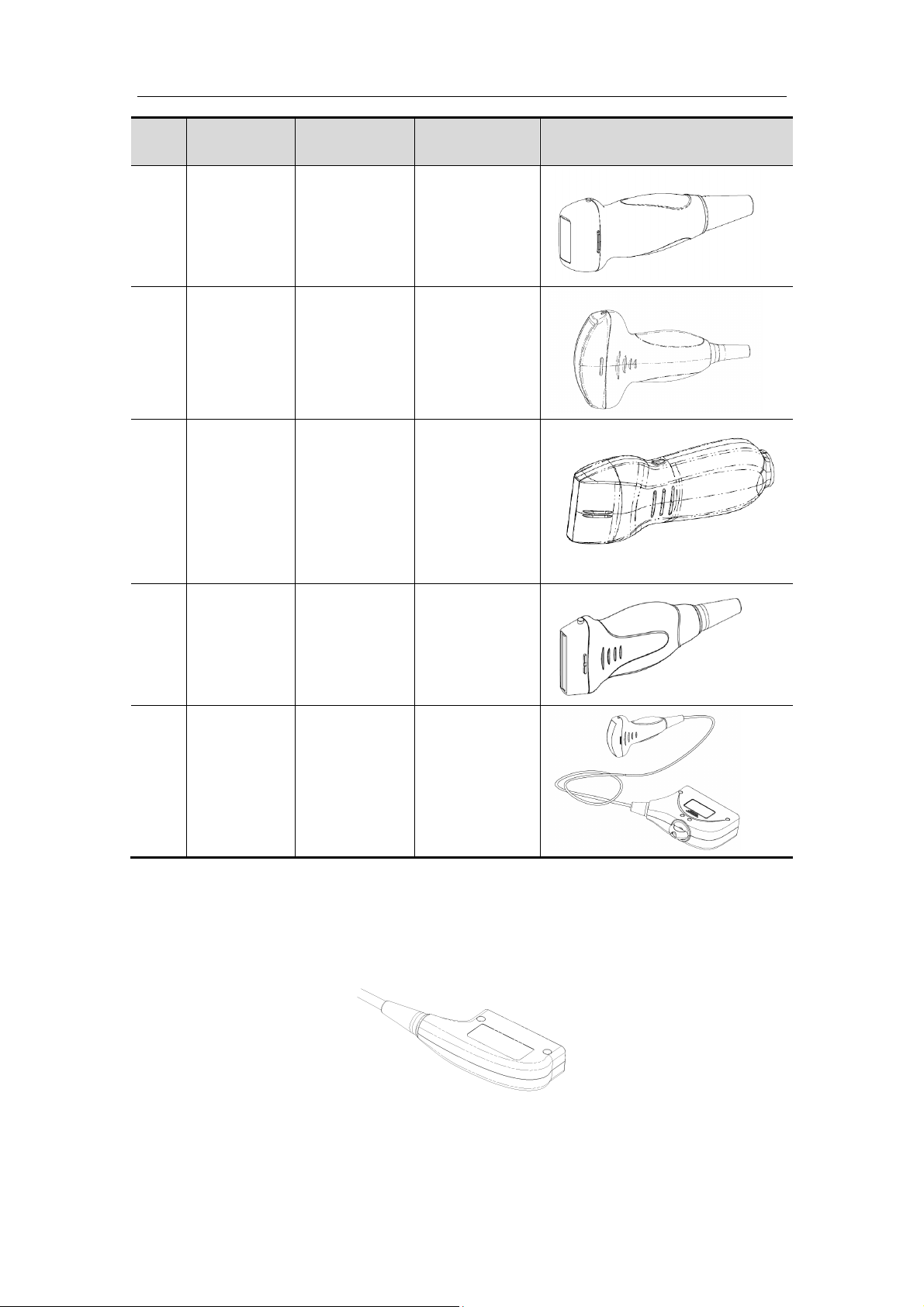
Overview
No. Model Type
89.
90.
91.
SP5-1U
SC5-1U
L20-5U
Phased Body surface
Convex Body surface
Linear Body surface
Applied
region
Illustration
92.
LM16-4U
Linear Body surface
93.
C5-1E
Convex Body surface
Tips: the transducer whose model is ended with an “s” (7L5s, for example) is to be used
with the Doppler ultrasound system, except the connector of this transducer, other parts
are the same as the corresponding transducer whose model is not ended with an “s” (7L5,
for example). See the figure below for the connector of the transducer whose model is
ended with an “s”.
1-15
Page 30

1.4.2 Needle-guided Bracket Model
Overview
Model Matched
Transduce
r(s)
NGB-001
NGB-002
NGB-003
NGB-004
35C50HA
35C50EA
35C50EB
35C50P
75L38HA
75L38HB
75L38EA
75L38EB
75L38P
35C20HA
35C20EA
65EC10EA
65EC10EB
65EC10EC
65EC10ED
65EC10HA
65EC10HC
65EC10HD
65EB10EA
6CV1(s)
6CV1P
V10-4(s)
V10-4B(s)
V10-4BP
CB10-
4CB10-4P
CB10-4E
V11-3E
V11-3BE
V11-3WE
V11-3Ws
V11-3
V11-3B
Type Biopsy
Angle/Depth
(±1°)
Metal/needle undetachable
Metal/needle
detachable
Metal/needle undetachable
Metal/needle undetachable
Metal/needle
detachable
Metal/needle undetachable
25°, 35°, 45° 13G, 15G, 16G, 18G, 20G
25°, 35°, 45° 14G, 16G, 18G, 20G, 22G
40°, 50°, 60° 13G, 15G, 16G, 18G, 20G
11°, 23° 13G, 15G, 16G, 18G, 20G
11°, 23° 14G, 16G, 18G, 20G, 22G
/ 16G, 17G, 18G
Applicable Biopsy
Needle
1-16
Page 31

Overview
Model Matched
Transduce
r(s)
NGB-005
NGB-006
NGB-007
NGB-008 3C1(s)
65C15HA
65C15EA
65C15EAV
6C2(s)
6C2P
3C5(s)
3C5A
3C5P
7L4(s)
7L4A
7L4P
10L4(s)
75L53EA
75L53HA
7L5(s)
7L5P
L7-3(s)
L7-3E
L11-4(s)
L12-4(s)
L14-6Ns
L14-6NE
L12-3E
L14-6WE
L14-6Ws
L14-6WU
Type Biopsy
Angle/Depth
(±1°)
Metal/needle undetachable
Plastic/needle
detachable,
metal
Metal/needle
detachable
Plastic/needle
detachable,
metal
Metal/needle
detachable
Plastic/needle
detachable,
metal
12.7°, 24.2° 13G, 15G, 16G, 18G, 20G
25°, 35°, 45° 13G, 15G, 16G, 18G, 20G
25°, 35°, 45° 14G, 16G, 18G, 20G, 22G
40°, 50°, 60° 13G, 15G, 16G, 18G, 20G
40°, 50°, 60° 14G, 16G, 18G, 20G, 22G
11°, 23° 13G, 15G, 16G, 18G, 20G
Applicable Biopsy
Needle
NGB-009
6LB7(s)
6LE7(s)
6LE7P
65EL60EA
65EL66HA
Metal/needle
detachable
Metal/needle
detachable
11°, 23° 14G, 16G, 18G, 20G, 22G
/ 13G, 15G, 16G, 18G, 20G
1-17
Page 32

Overview
Model Matched
Transduce
r(s)
NGB-010
NGB-011
NGB-012
7LT4(s)
7LT4P
75LT38EA
75LT40HA
2P2(s)
2P2P
P4-2(s)
P4-2E
P4-2NE
SP5-1s
SP5-1E
SP5-1U
75L60HB
75L60EA
7L6(s)
Type Biopsy
Angle/Depth
(±1°)
Metal/needle
detachable
Metal/needle undetachable
Plastic/needle
detachable,
metal
Metal/needle
detachable
30°, 40°, 50° 13G, 15G, 16G, 18G, 20G
11°, 23° 13G, 15G, 16G, 18G, 20G
40°, 50°, 60° 13G, 15G, 16G, 18G, 20G
40°, 50°, 60° 14G, 16G, 18G, 20G, 22G
Applicable Biopsy
Needle
NGB-015 C5-2(s)
C5-2E
NGB-016 L14-6(s)
L14-6P
10L24EA
NGB-018 C11-3E/
C11-3s
NGB-019 C7-3E
NGB-022 C5-1U
NGB-023 LM14-6E
LM14-6s
LM16-4U
NGB-024 C6-2Gs
NGB-025 V11-3HU
Metal/needle
detachable
Metal/needle
detachable
Metal/needle
detachable
Metal/needle
detachable
Metal/needle
detachable
metal/needle
detachable
metal/needle
detachable
metal/needle undetachable
25°, 35°, 45° 14G, 16G, 18G, 20G, 22G
30°, 40°, 50° 14G, 16G, 18G, 20G, 22G
14G, 16G, 18G, 20G, 22G
15°, 25°, 35°
20°, 30°, 40° 14G, 16G, 18G, 20G, 22G
25°, 35°, 45° 14G, 16G, 18G, 20G, 22G
40°, 50°, 60° 14G, 16G, 18G, 20G, 22G
7°, 25°, 30° 14G, 16G, 18G, 20G, 22G
1.6° 16G, 17G, 18G
NGB-026 L11-3U
metal/needle
detachable
40°, 50°, 60° 14G, 16G, 18G, 20G, 22G
1-18
Page 33
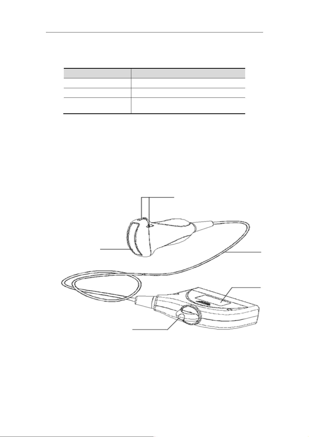
Overview
1.5 Composition
The following items are supplied with each transducer.
Items Quantity
Ultrasonic transducer 1
Operator’s manual 1
Syringe 1( for 6LE7(s/P), 6LB7(s), 65EL60EA,
65EL66HA only)
1.5.1 Transducer Functions by Part
This section describes the name and function of each part as well as the immersible
range of the ultrasonic transducer.
The transducer is classified as "IPX7" according to the degree of protection against
harmful ingression of water (from the transducer head to the cable protector).
The connector is not waterproof and must not be immersed into liquids such as
disinfectant.
The transducer is shown as follows (take 3C5A as an example):
<2>
<1>
<5>
<3>
<4>
1-19
Page 34
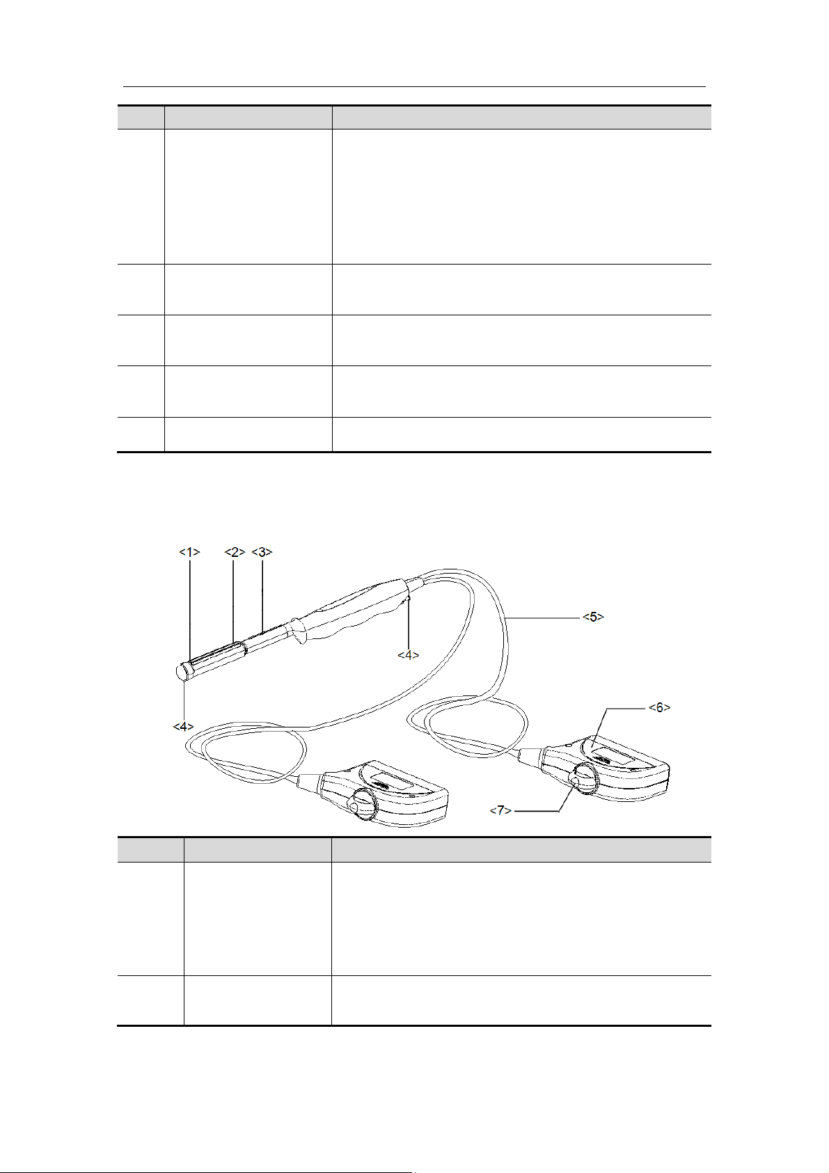
Overview
No. Name Function
<1> Transducer head Converts the electrical signal into an ultrasonic signal,
focusing the sound beams in a given direction;
meanwhile, it receives the reflected ultrasonic signal
and converts it into an electrical signal for transmission
over the cable. The lens on the surface is the acoustic
lens. Apply ultrasound gel on the acoustic lens for
correct operation.
<2> Needle-guided bracket
fix tabs and grooves
Provides mounting support of the needle-guided
bracket.
<3> Transducer cable Transmits electrical signals between the transducer
body and connector.
<4> Transducer connector Connects the transducer and cable to the ultrasonic
diagnostic system.
<5> Lock handle Locks the connector to the ultrasonic diagnostic system.
Tips:
The transducers’ structure marked <2> in the figure above may vary with the matched
needle-guided brackets.
Biplanar transducer 6LB7:
No. Name
<1>Transducer head
<1>
<2>
<3>
(convex)
<2>Transducer head
(linear)
Needle-guided
bracket fix tab
Function
Converts the electrical signal into an ultrasonic signal,
focusing the sound beams in a given direction; meanwhile,
it receives the reflected ultrasonic signal and converts it
into an electrical signal for transmission over the cable.
The lens on the surface is the acoustic lens. Apply
ultrasound gel on the acoustic lens for correct operation.
Supports mounting of the needle-guided bracket.
1-20
Page 35

Overview
No. Name
Water
<4>
<5>
<6>
<7>
injection/drainage
port
Cable
Connector
Lock handle Locks the connector to the ultrasonic diagnostic system.
Function
Provides an interface for injecting and draining water.
Transmits electrical signals between the transducer body
and connector.
Connects the transducer and cable to the ultrasonic
diagnostic system.
1-21
Page 36
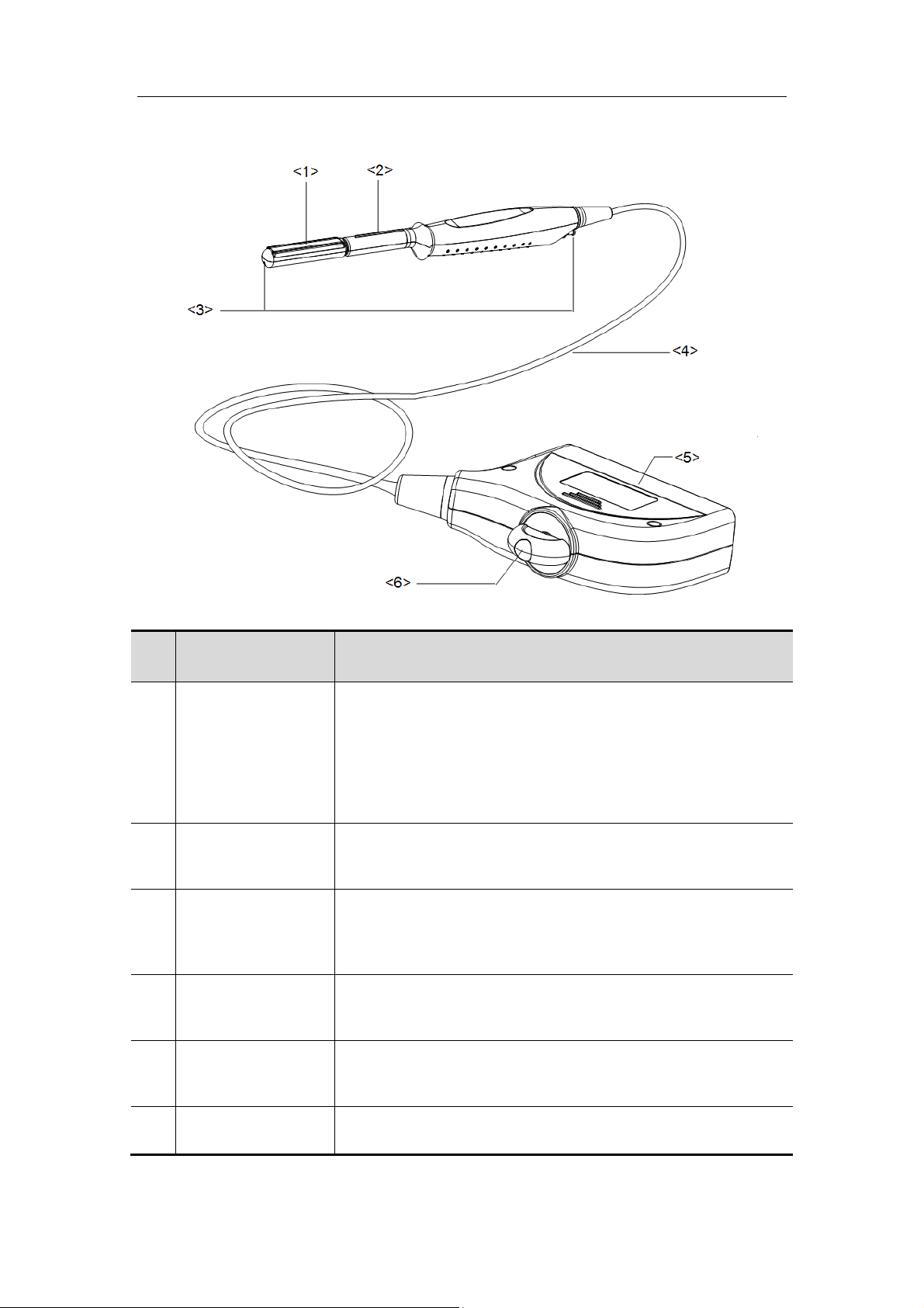
6LE7:
Overview
No. Name Function
Converts the electrical signal into an ultrasonic signal,
focusing the sound beams in a given direction; meanwhile, it
<1> Transducer head
Needle-guided
<2>
bracket fix tab
Water
<3>
injection/drainage
port
<4> Cable
receives the reflected ultrasonic signal and converts it into an
electrical signal for transmission over the cable. The lens on
the surface is the acoustic lens. Apply ultrasound gel on the
acoustic lens for correct operation.
Mount the needle-guided bracket using this tab.
Used for inject/drain water
This transmits electrical signals between the transducer body
and connector.
<5> Connector
<6> Lock handle This locks the connector to the ultrasonic diagnostic system.
This connects the transducer to the ultrasonic diagnostic
system.
1-22
Page 37
Overview
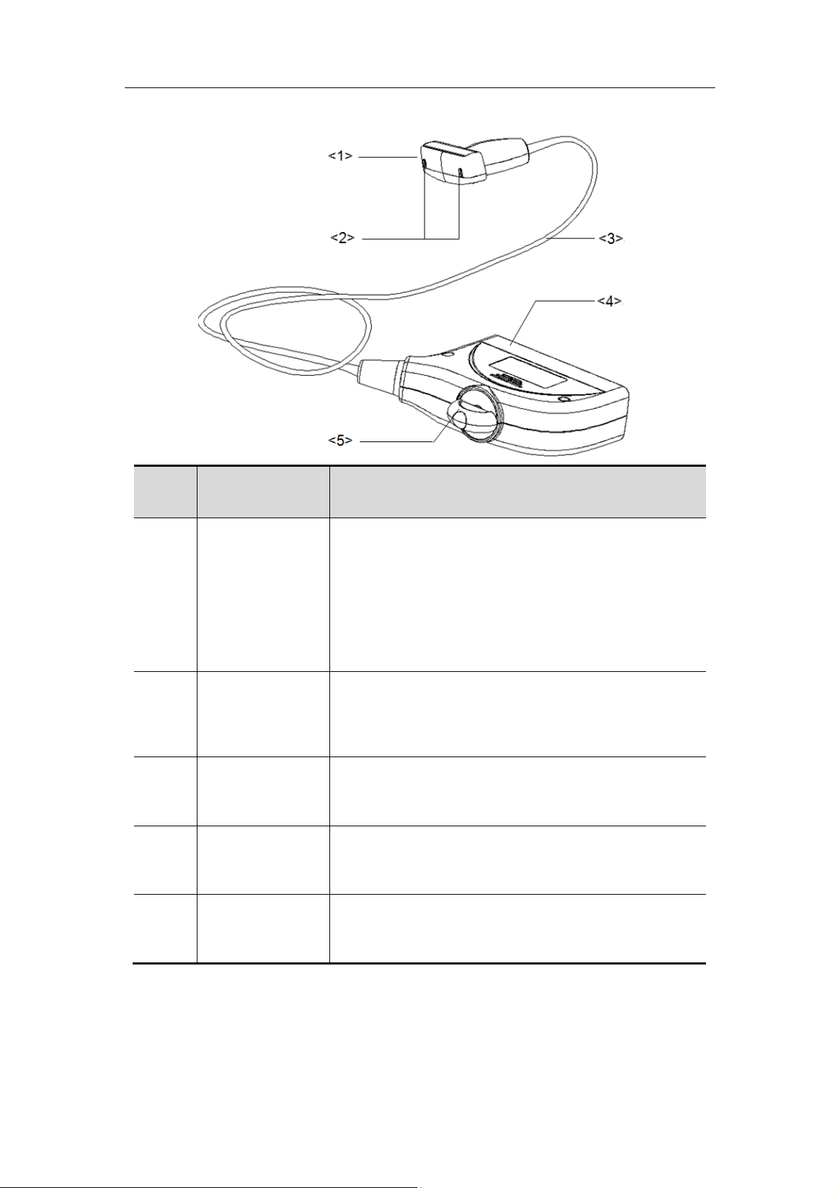
Intraoperative transducers 7LT4/7LT4s/75LT38EA/75LT40HA (Take 7LT4 as an example):
No. Name Function
Converts the electrical signal into an ultrasonic signal,
focusing the sound beams in a given direction;
meanwhile, it receives the reflected ultrasonic signal
<1> Transducer head
Needle-guided
<2>
<3> Cable
<4> Connector
bracket fix
grooves
and converts it into an electrical signal for transmission
over the cable. The lens on the surface is the acoustic
lens. Apply ultrasound gel on the acoustic lens for
correct operation.
Mounts the needle-guided bracket using these
grooves.
Transmits electrical signals between the transducer
body and connector.
Connects the transducer to the ultrasonic diagnostic
system.
<5>
Lock handle (not
for 7LT4s)
Locks the connector to the ultrasonic diagnostic
system.
1-23
Page 38

Overview
1.6 Procedures for Operating the
Transducer
This section describes general procedures for operating the transducer.
The proper clinical technique to be used for operating the transducer should be selected
on the basis of specialized training and clinical experience.
1-24
Page 39
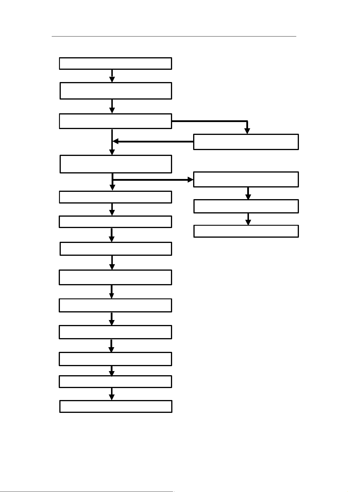
Procedures for operating (with biopsy function):
Inspection before examination
Connection to the ultrasonic
diagnostic system
Examinations
Disconnection to the ultrasonic
diagnostic system
Wiping off the ultrasound gel
Overview
Biopsy procedure
Sterilization of the needle-
guided bracket
Inspection after use
Washing the transducer with water
Draining/drying
Immersion into disinfectant
Removing the transducer
from disinfectant
Rinsing the transducer in sterile water
Draining/drying
Inspection after use
Storage
Storage
1-25
Page 40
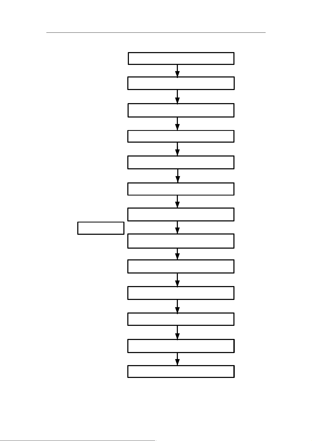
Procedures for operating (with no biopsy function):
Inspection before examination
Connection to the ultrasonic
Disconnection to the ultrasonic
Wiping off the ultrasound gel
Overview
diagnostic system
Examinations
diagnostic system
Disinfection
Washing the
transducer with water
Draining/drying
Immersion into disinfectant
Removing the transducer
from disinfectant
Rinsing the transducer into sterile water
Draining/drying
Inspection after use
Storage
1-26
Page 41

WARNING:
Overview
Disinfect the transducer and sterilize the needle-guided
bracket before and after an ultrasound-guided biopsy
procedure is performed. Failure to do so may cause the
transducer and the needle-guided bracket become source of
infection.
1-27
Page 42

Page 43
2 Connecting the
Transducer to the System
The transducer can be used with compatible ultrasonic diagnostic systems.
NOTE: Before connecting or disconnecting a transducer, freeze or turn off the
ultrasonic diagnostic system, otherwise the ultrasonic diagnostic system or
the transducer may malfunction.
2.1 Connecting and Disconnecting the
Transducer
For non-portable Doppler Ultrasound System Compliant Transducer
Connecting the transducer:
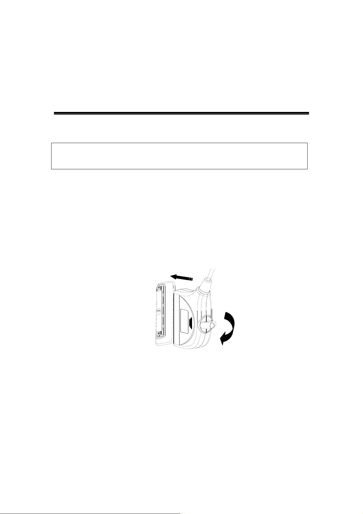
After freezing or turning off the ultrasonic diagnostic system, align the connector with the
transducer connector port of the ultrasonic diagnostic system, then turn the lock handle
90° clockwise to lock it securely. See the figure below:
LOCK
Disconnecting the Transducer:
After freezing or turning off the ultrasonic diagnostic system, turn the lock handle 90°
anticlockwise to unlock the transducer. Remove the connector by pulling it out straight.
See the figure below:
2-1
Page 44
Connecting the Transducer to the System
For Portable Doppler Ultrasound System Compliant Transducer
Connecting the transducer:
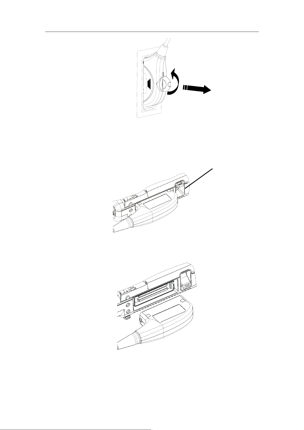
To connect the transducer, insert the connector fully into the socket. Toggle the transducer
lock lever, which beside the socket, to the upper position. See the figure below.
transducer lock lever
Disconnecting the Transducer:
To disconnect the transducer, toggle the transducer lock lever to the lower position, and pull
out the transducer evenly from the socket. See the figure below.
2-2
Page 45
3 Inspection Before and
After Use
Inspection before and after use must be performed as described below to ensure safe
operation of the transducer.
If any abnormality is found, immediately stop using the transducer and contact MINDRAY
Customer Service Department or sales representative.
3.1 Check the External Appearance of the
Transducer
Confirm that there are no abnormalities of the transducer surface or cable sheath, such
as peeling, cracks, protruding parts, or looseness of the acoustic lens, before and after
each examination.
WARNING:
Transducer abnormalities may cause electric shock or injury
to the patient. If any abnormality is found, immediately stop
using the transducer and contact your MINDRAY Customer
Service Department or sales representative.
3.2 Cleaning the Transducer
Clean and disinfect the transducer before and after each examination.
CAUTION:
If you don’t clean and disinfect the transducer, it may become a
source of infection.
3.3 Checking after Turning on the System
After turning ON the power of the ultrasonic diagnostic system, perform the following
checks.
1. The acoustic lens of the transducer must not generate abnormal heat while it is being
used. The transducer temperature should be checked by hand.
CAUTION:
2. The image must not be abnormal while turning on the system.
CAUTION:
If you keep a hot acoustic lens on the body surface, the patient
may be burned.
Any of the problems mentioned above indicates that the ultrasonic
diagnostic system or the transducer may be defective.
3-1
Page 46

Page 47
4 Operating Procedures
This section describes general procedures for operating the transducer.
The operator should have adequate clinical experience and received related training.
CAUTION:
1. Clean and disinfect the transducer before and after each
examination.
2. When using the transducer, wear sterile gloves to prevent
infection.
4.1 Orientation of the Ultrasound Image
and the Transducer Head
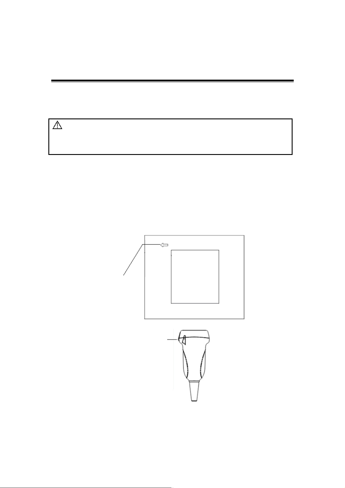
The orientation of the ultrasound image and the transducer are shown as below (using
linear transducer as an example). The “MARK” side of the ultrasound image on the
monitor corresponds to the mark side of the transducer. Check the orientation before the
examination.
Orientation mark
Mark
Orientation of the Ultrasound Image and the Transducer Head
4-1
Page 48
Operating Procedures
4.2 Utilizing the Transducer Sheath
A legally marketed transducer sheath must be installed over the transducer before
performing intra-cavitary examination. Protective barriers may be required to minimize
disease transmission. Transducer sheaths are available for use with all clinical situations
where infection is a concern.
To order transducer sheath, contact:
CIVCO Medical Instruments Co.
102 First Street South, Kalona, IA 52247-9589 USA Tel: 1-319-656-4447
E-mail: [email protected]
http://www.civco.com
CAUTION:
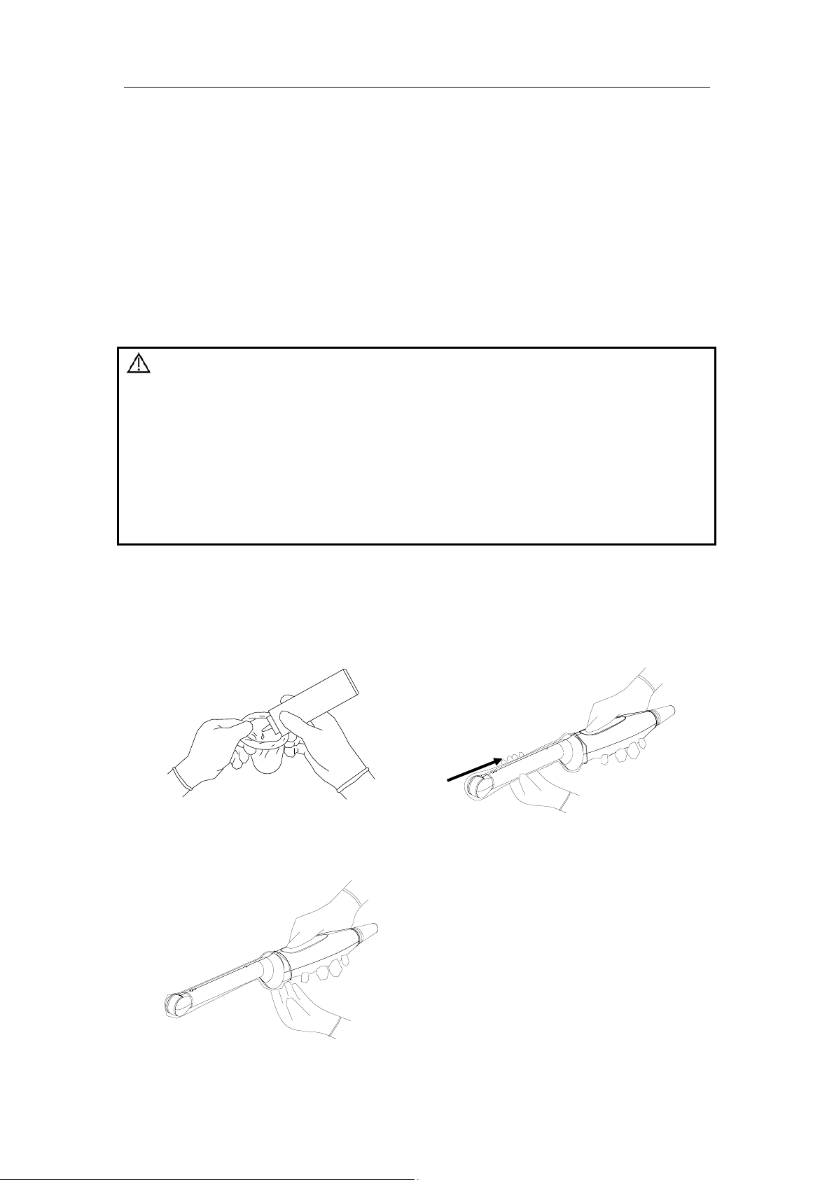
Method (for reference only):
1. Place an appropriate amount of gel
inside the sheath or on the transducer
acoustic lens. Poor imaging may result
if no gel is used.
1. Be sure to cover the transducer with a new (unused)
transducer sheath to prevent infection during examination. If
the package of a transducer sheath is open or broken, the
sterilization of the transducer sheath may not be sufficient.
DO NOT use such a transducer sheath.
2. The cover contains natural rubber latex and talc that can
cause allergic reactions in some individuals.
3. DO NOT use an expired transducer sheath. Before using
transducer sheaths, verify whether the term of validity has
expired.
2. Insert the transducer into the sheath.
Pull cover tightly over transducer
acoustic lens to remove wrinkles and
air bubbles, and taking care to avoid
puncturing the sheath.
3. Secure the sheath with the enclosed
elastic bands.
4. Inspect the sheath to ensure there are
no holes or tears.
4-2
Page 49
Operating Procedures
4.3 When the Immersion Method is Used
Water immersion is required when performing an ultrasound exam using transducers,
including 6LE7(s), 6LB7(s), 65EL60EA, and 65EL66HA.
The Mindray recommends using syringe: CIVCO 610-224. Transducer 6LB7 is used as
an example to describe the immersion method.
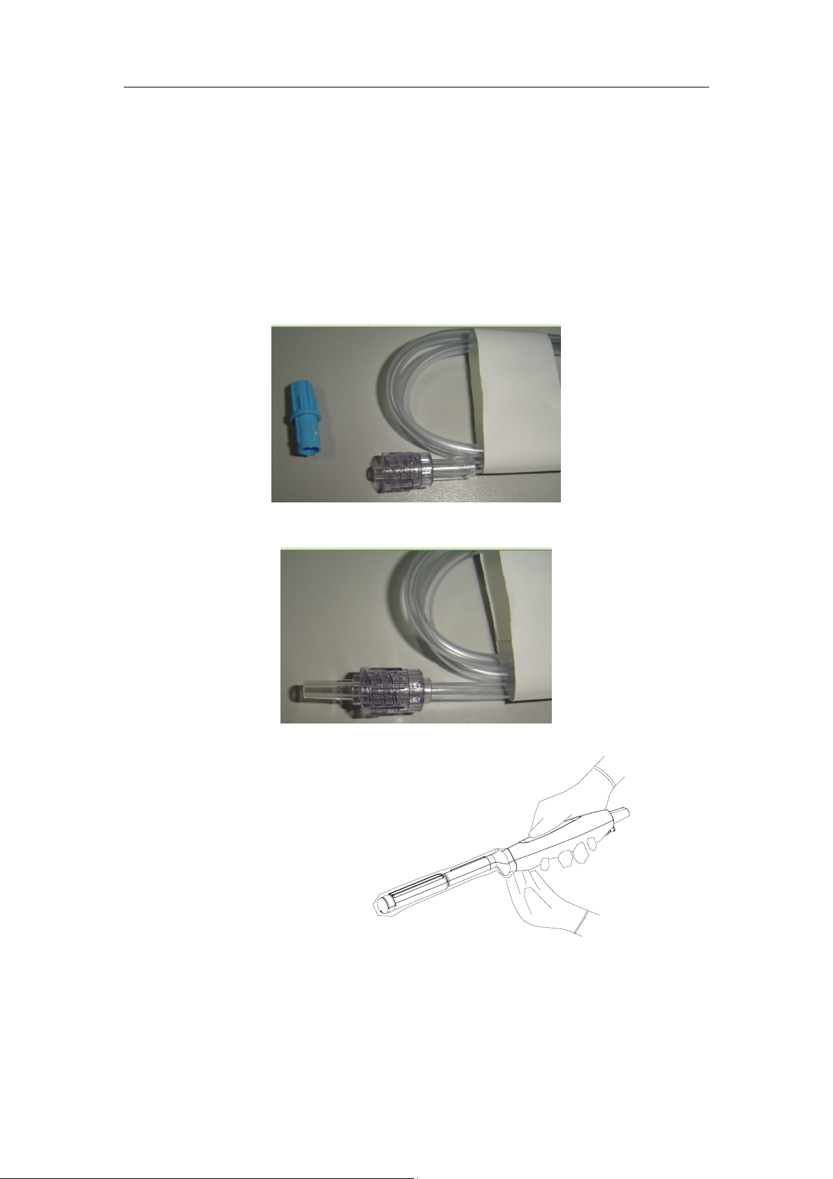
Perform the following operations before using the syringe.
1. Open the syringe pack and remove the syringe.
2. Take out the dustproof cap at the end of the syringe’s extension tube, as shown in
the following figure.
3. Push back the locking nut to extend the connector, as shown in the following figure.
The connector should be connected to the transducer’s injection/drainage port.
Please refer to the following operations when the immersion method is used.
1. Put on the transducer cover.
For the procedures of putting
on the transducer sheath,
refer to subsection above.
Check the transducer sheath
for wrinkles and gaps.
4-3
Page 50
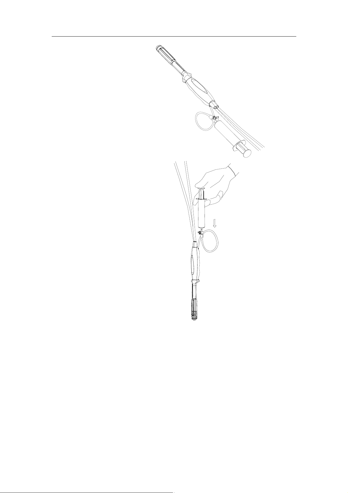
2. Fill syringe with sterile water
and connect extension tube to
syringe, discharge all air in the
tube. Attach the syringe to
transducer fill port.
3. Orient transducer downward
and inject sterile water up to
the level a few cm above the
end of the transducer surface.
Operating Procedures
4-4
Page 51
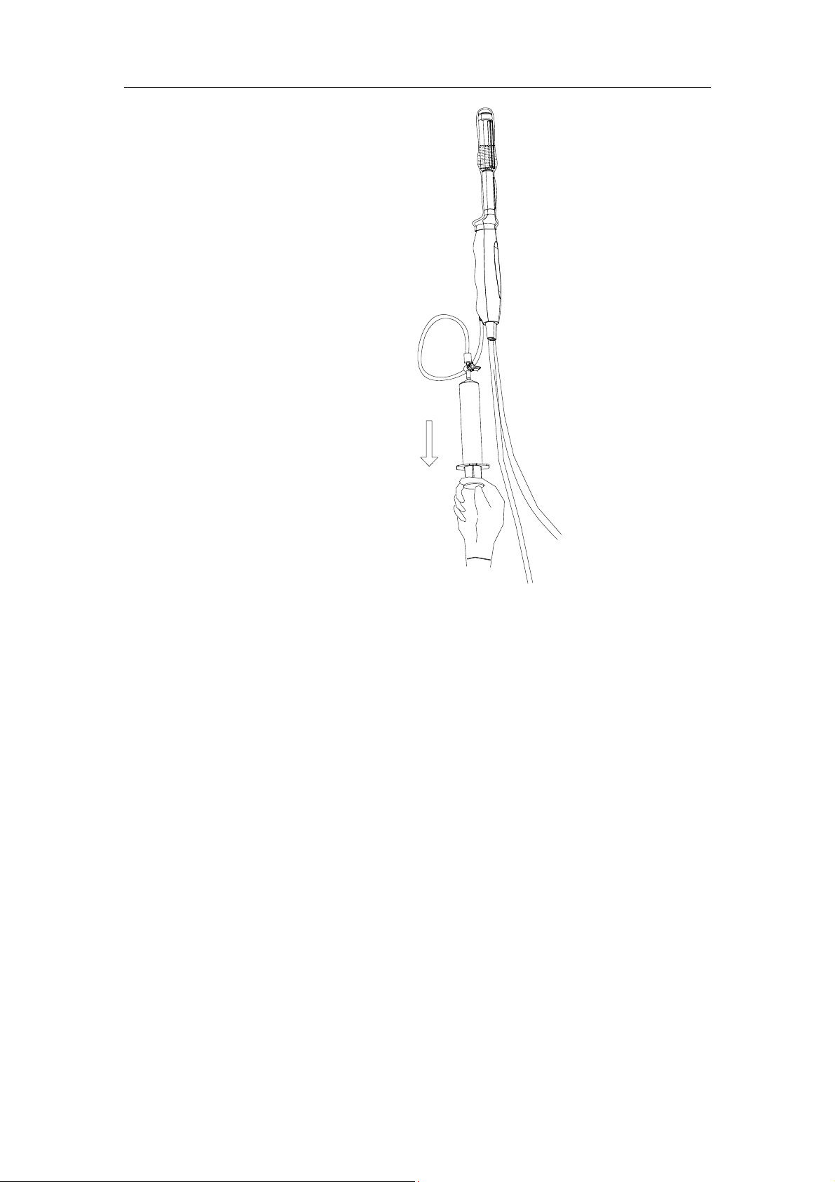
4. Orient transducer upward to
discharge air in transducer
cover.
Operating Procedures
4-5
Page 52
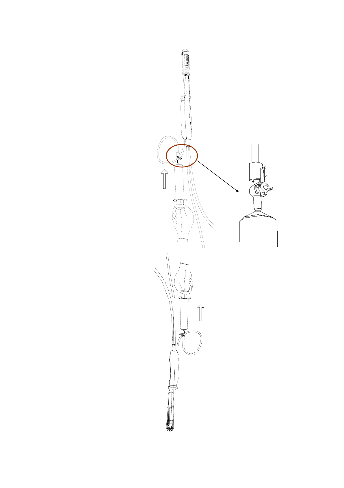
5. Turn the valve of the syringe
to the position shown in the
right figure, and then push the
plunger of the syringe to
discharge the air.
Operating Procedures
6. Return the valve of the
syringe to the original position;
orient the transducer
downward to discharge sterile
water.
4-6
Page 53

Operating Procedures
4.4 Examinations
The operator should adopt proper ultrasonic scanning procedures and methods
according to different target organs.
NOTE: It is required to practice ALARA when operating ultrasonic diagnostic system.
4.5 After Examinations
After the examination is completed, turn OFF the ultrasonic diagnostic system and refer
to Chapter 5 “Cleaning and Disinfection” to clean and disinfect the transducer.
After completing each examination, disinfect the transducer as necessary.
After disinfecting the transducer, confirm that the transducer is in good condition and
store it in a suitable place so that the next examination can be conducted smoothly.
4-7
Page 54

Page 55
5 Cleaning and Disinfection
After completing each examination, clean and disinfect (or sterilize) the probes as
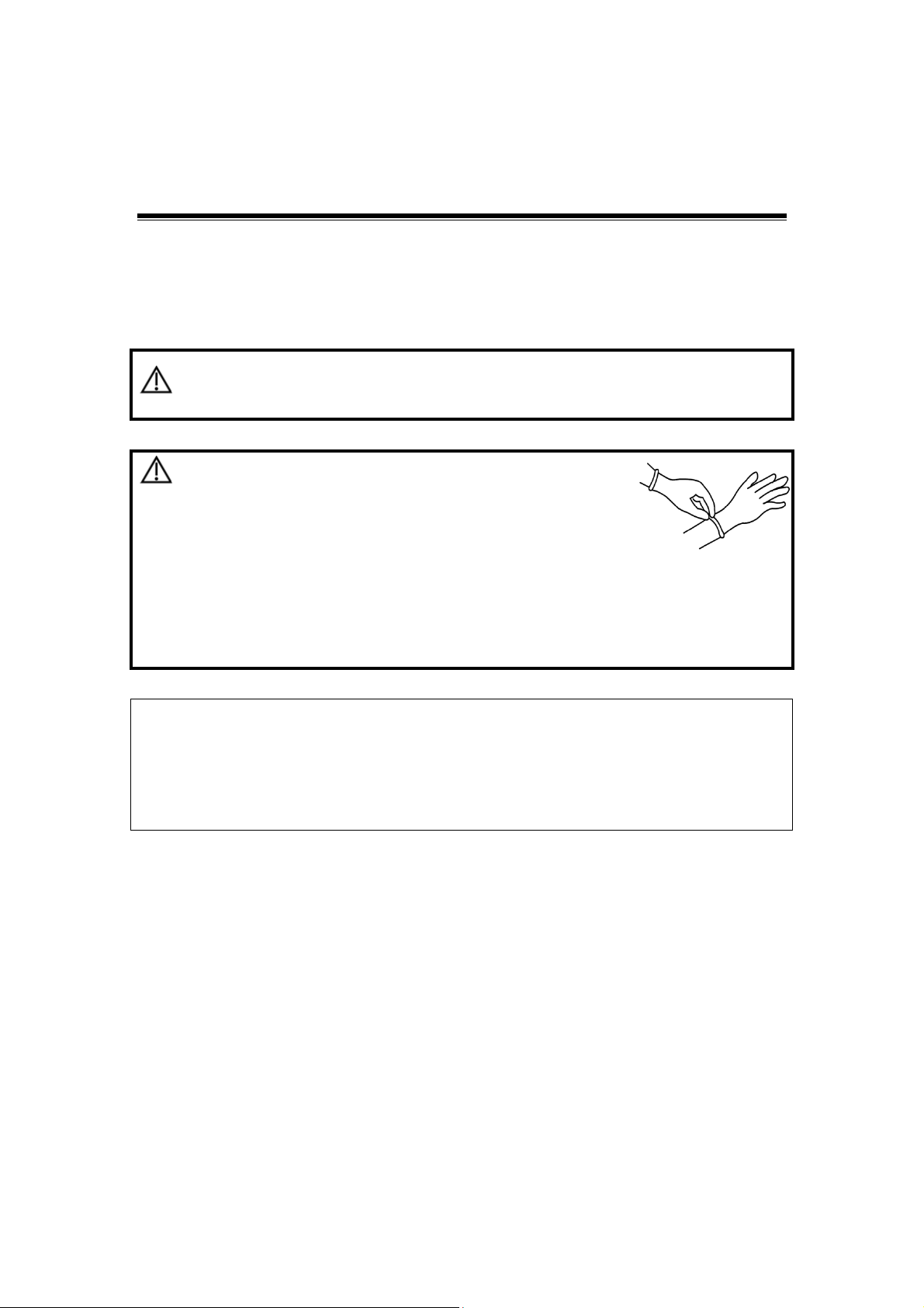
required. When biopsy procedures have been performed, be sure to sterilize the needleguided bracket. Fail to do so may result in the probe and the needle-guided bracket to
becoming sources of infection. Please follow the instructions in the manual for cleaning.
Never immerse the probe connector into liquid such as
WARNING:
water or disinfectant. Immersion may cause electrical shock
or malfunction.
CAUTION:
NOTE: 1. After the examination, wipe off the ultrasound gel thoroughly. Otherwise,
the ultrasound gel may solidify and degrade the image quality of the
transducer.
2. DO NOT make the probe to become overheated (more than 55°C) during
cleaning and disinfections. High temperature may cause the probe to
become deformed or damaged.
1. When performing cleaning and
disinfection of the probe to prevent
infection, wear sterile gloves.
2. After disinfection, rinse the probe thoroughly with sterile
water to remove all chemical residues. Chemical residues
on the probe may be harmful to the human body.
3 No cleaning and disinfecting may result in the probe
becoming a source of infection.
5.1 Cleaning
Please refer to the instructions in the manual and follow your hospital policy and
procedures for cleaning.
1. Disconnect the probe from the system.
2. Wear sterile gloves to prevent infection.
3. Wash the transducer with clean water or soapy water to remove all the foreign
matters, or, wipe the transducer with a soft ethyl carbamate sponge. Avoid using a
brush, because it may damage the transducer.
4. Dry the transducer using a sterile cloth or gauze after rinsing. Do not dry the
transducer by heating it.
5-1
Page 56
5.2 High Level Disinfections
Disinfecting with Sprays or Wipes
Cleaning and Disinfection
CAUTION:
1. Wear sterile gloves to prevent infection.
2. After you have finished cleaning, spray or wipe the transducer with a disinfectant.
Follow the disinfectant manufacturer’s recommended contact time and mode.
3. Remove any residue with a water-moistened soft cloth on the transducer.
4. Wipe off water on the transducer using sterile cloth or gauze after washing.
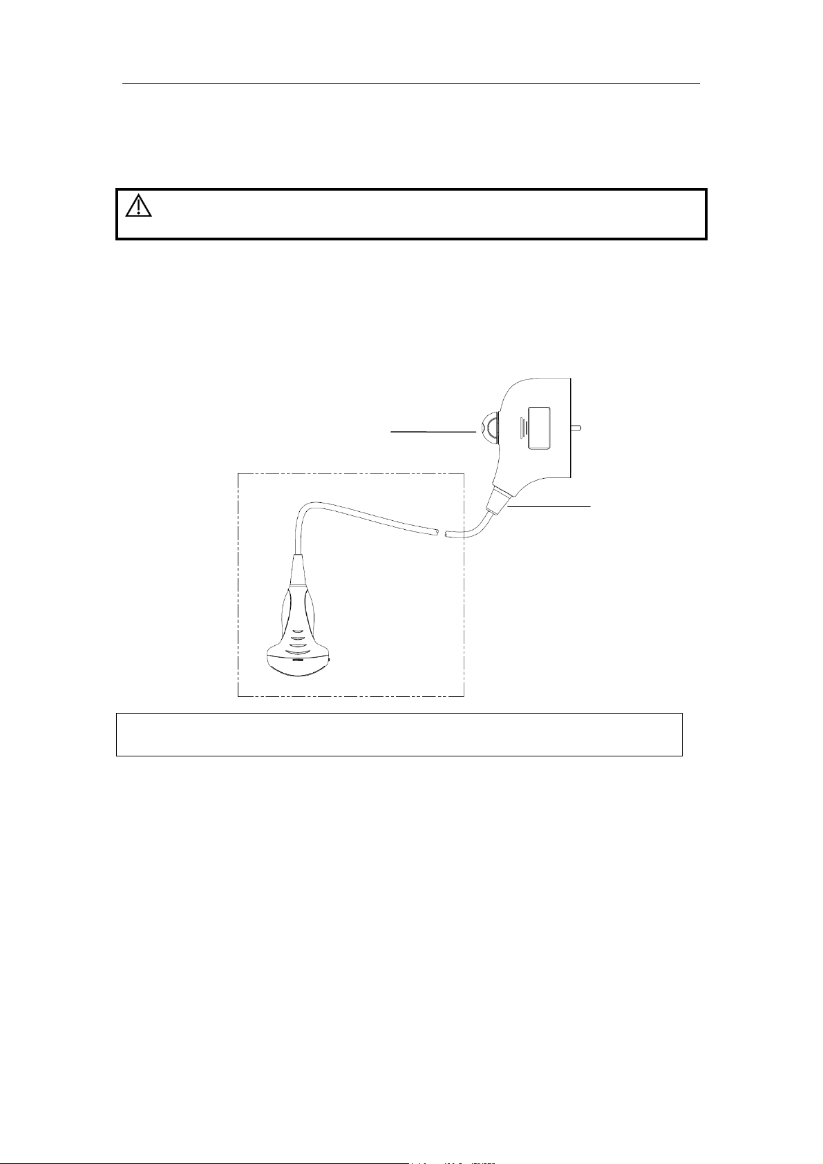
Use protective eyewear when disinfecting using
sprays.
Connector
Strain relief
NOTE: Observe the graph here carefully to perform disinfection. Do not spray the
strain relief on the connector end or the connector.
Disinfecting by Immersion
1. Wear sterile gloves to prevent infection.
2. Clean the transducer before disinfecting it. MINDRAY recommends the following
solutions to disinfect the transducer.
z Refer to the instructions provided by the chemical manufacturer concerning
concentration of the disinfectant solution, method of disinfection and dilution and
cautions during use. Do not soak the transducer connector or the cable near it
into water or any solution.
z Soak the transducer into the disinfectant solution for the shortest time the
manufacturer recommends (for example, the shortest time recommended by the
manufacturer for soaking Cidex OPA is 12 minutes).
z Follow local regulations when selecting and using the disinfectant.
5-2
Page 57
Cleaning and Disinfection
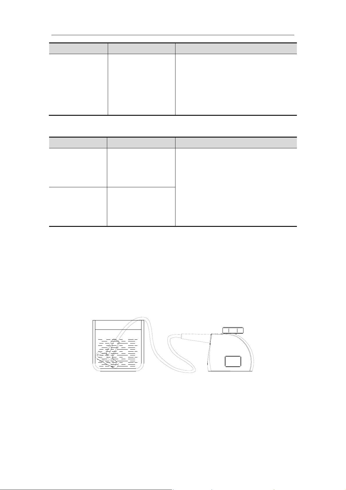
3. Rinse the transducer with plenty of sterile water (about 2 gallons) for at least 1
minute to remove all chemical residues on it.Or, follow the rinsing method
recommended by the disinfectant manufacturer to rinse the transducer.
4. Wipe off the water on the transducer with sterile cloth or gauze after rinsing it. Do not
dry the transducer by heating.
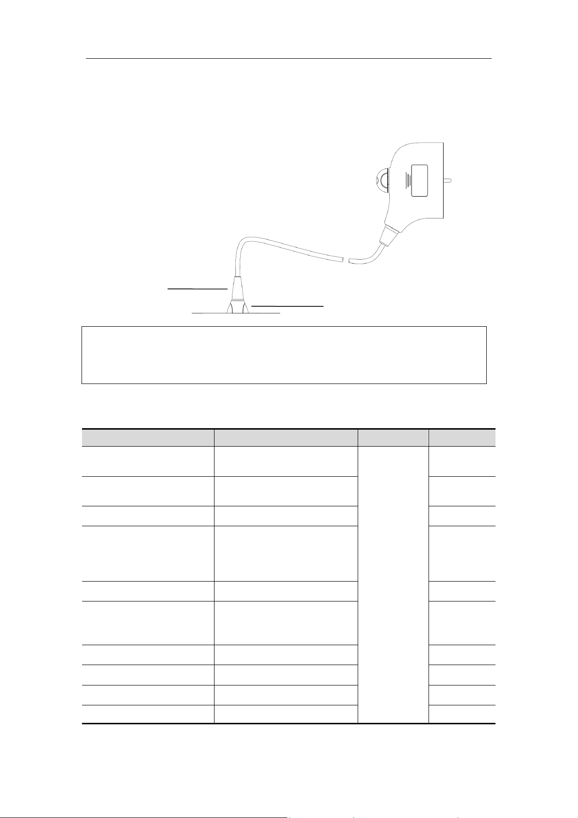
Strain relief
Probe handle
NOTE: 1. Observe the graph here carefully to immerse the transducer. Only soak
parts of the transducer below the strain relief.
2. Repeated disinfection will eventually damage the probe, please check
the probe performance periodically.
Compatible Disinfectants
Manufacturer Trade Name Procedures Type
Pharmaceutical
Innovations, Inc.
Parker Laboratories Inc.
T-Spray II
PROTEX
SPRAY
TM
DISINFECTANT
Metrex MetriZyme
Cidex Activated
ASP
Glutaraldehyde Solution
(Cidex Activated Dialdehyde
Solution for FDA region)
ASP Cidex OPA Solution
TrophonSonex-HL (Used with
Nanosonics Limited
Trophon EPR Ultrasound
Probe Disinfector)
Please refer
to the
instructions
provided by
the
manufacturer
of the
solution for
details.
Spray*
Spray*
Solution*
Solution*
Solution*
Ecolab Inc. Ster-Bac Solution
Antiseptica Triacid-N Solution*
Minntech Corporation Minncare® Cold Sterilant Solution*
Parker Laboratories Inc. TRANSEPTIC Spray*
5-3
Page 58

Cleaning and Disinfection
Manufacturer Trade Name Procedures Type
TM
Parker Laboratories Inc.
PROTEX
WIPES
DISINFECTANT
Wipe****
Tristel Solutions Limited Tristel Solo Spray*
Diversey Oxivir
TM/MC
Tb Spray
Advanced Ultrasound
Solutions Inc.
SONOTM ULTRASOUND
WIPES
Wipe
Anios Laboratoires Wip'Anios premium Wipe***
Anios Laboratoires Surfa'safe Spray
PDI Sani-Cloth® Plus Wipe
DR.SCHUMACHER
GMBH
Steris
CLEANISEPT® WIPES Wipe**
TM
Rivital-Ox
Level Disinfectant
Resert High
Solution*****
5-4
Page 59

Cleaning and Disinfection
*denotes if the disinfectant is not applicable for following probes: 3C5s, LM14-6E,
3C5A, 3C5P, LM16-4U, L12-3E, L14-6Ws, C5-1U, L14-6WE, C5-2, L12-4s, L146WU, C5-2s, L12-4, C5-1s, C5-2E, C5-2E, L14-6N, L14-6Ns, L14-6NE, L14-6, L11-4,
L14-6s, L11-4s, L14-6P, SC6-1U, 10L24EA
**denotes if the disinfectant is not applicable for following probes: 2P2, 35C20EA,
C7-3E, 2P2s, 35C20HA, C11-3s, 2P2P, 35C50EA, C11-3E, 3C1, 35C50EB, P4-2,
3C1s, 35C50HA, P4-2s, 65C15EA, P4-2E, 6C2, 65C15EAV, P4-2NE, 6C2s,
65C15HA, 6C2P, 75L38EA, P10-4E, 7L4, 75L38EB, P10-4s, 7L4s, 75L38HA, L7-3,
7L4A, 75L53EA, L7-3s, 7L4P, 75L53HA, L7-3E, 7L5, 75L60EA, 7L5s, 75L60HB,
7L5P, 7L6, 35C50P, 7L6s, 75L38P, 65EL66HA, 6LE7, 6LE7s, 6LE7P, 6LB7, 6LB7s,
65EB10EA, CB10-4, CB10-4P, CB10-4E
***denotes if the disinfectant is not applicable for following probes: 3C5s, LM14-6E,
3C5A, 3C5P, LM16-4U
****denotes if the disinfectant is not applicable for following probes: L14-6, L11-4,
L14-6s, L11-4s, L14-6P, SC6-1U, 10L24EA
***** denotes if the disinfectant is applicable only for following probes: 6CV1, V10-4B,
6CV1s, V10-4Bs, 6CV1P, V10-4BP, V10-4, 65EC10ED, V10-4s, 65EC10HD
TM
Disinfectant applicable for the probe SP5-1s, SP5-1E,SP5-1U: SONO
ULTRASOUND WIPES, Oxivir
TM/MC
Tb, Wip'Anios premium, Surfa'safe, Sani-Cloth®
Plus
Disinfectant applicable for the probe C6-2GE, V11-3HU, L11-3U: Cidex OPA, SONO
WIPES, Oxivir
TM/MC
, Sani-Cloth, cleanisept
Disinfectant applicable for the probe P7-3, P7-3s, P7-3E, P7-3P, P12-4, P12-4s,
CW2s, CW5, 10L4, 10L4s: Cidex OPA, Ster bac, Cidex
Disinfectant applicable for the probe L10-3E: MetriZyme, Protex disinfectant spray,
TrophonSonex-HL and T-Spray II
Disinfectant applicable for the probe SC5-1E, SC5-1U: CIDEX OPA, SONO WIPES,
Oxivir
TM/MC
, Sani-Cloth, wip anios, cleanisept
Disinfectant applicable for the probe L16-4HE: Cidex and Cidex OPA
Disinfectant applicable for the probe SC8-2U: MetriZyme, Cidex OPA and
TRANSEPTIC
Disinfectant applicable for the probe L20-5U: CIDEX,CIDEX Plus,T-Spray
5.3 Sterilization
For intra-operative transducers, they have to be sterilized after completing each
examination.
1. Wear sterile gloves to prevent infection.
2. Clean the transducer before sterilizing it. MINDRAY recommends the following
solutions to sterilize the transducer.
Hydrogen Peroxide and Peroxyacetic Acid -based sterilization solution
5-5
Page 60
Cleaning and Disinfection
Trade Name Chemical Name Procedures
Minncare® Cold
Sterilant
22% Hydrogen
Peroxide
4.5% Peroxyacetic
Acid
Dilute the sterilant with sterilized purified
water (1:20).
Immersed time: 11 hours.
Temperature: 20℃-25℃.
Please refer to the instructions provided
by the manufacturer of the solution for
details.
Glutaraldehyde-based sterilization solution
Trade Name Chemical Name Procedures
Cidex Activated
Glutaraldehyde
Solution
(applicable for CE
region)
Cidex Activated
Dialdehyde
Solution
2.2-2.7%
Glutaraldehyde
2.4% Glutaraldehyde
Soak the transducer into the activated
solution for 10 hours (20-25℃).
Please refer to the instructions provided
by the manufacturer of the solution for
details.
(applicable for
FDA region)
z Refer to the instructions provided by the chemical manufacturer concerning
concentration of the sterilization solution, method of sterilization and dilution and
cautions during use.
z Do not soak the transducer connector or the cable near it into water or any
solution.
z Follow local regulations when selecting and using the sterilization solution.
3. Rinse the transducer with plenty of sterile water (about 2 gallons) for at least 1 minute
to remove all chemical residues on it. Or, follow the rinsing method recommended by
the sterilization solution manufacturer to rinse the transducer.
4. Wipe off the water on the transducer with sterile cloth or gauze after rinsing it. Do not
dry the transducer by heating.
Immerse the intra-operative transducer in the solution (for reference)
Before safety and performance is affected, intra-operative probes can be sterilized by
Cidex Activated Glutaraldehyde Solution for at least 217 times (10 hours for one time).
Before safety and performance is affected, intra-operative probes can be sterilized by
Minncare COLD STERILANT for at least 135 times (11 hours for one time).
5-6
Page 61

Cleaning and Disinfection
CAUTION:
Repeated disinfection will eventually damage the transducer,
please check the transducer’s performance periodically.
5-7
Page 62

Page 63

6 Needle-guided Bracket
and Biopsy
For details about the needle-guided bracket and biopsy operations, please refer to the
needle-guided bracket operator’s manual.
6-1
Page 64

Page 65

7 Storage and
T
ransportation
Note: For details of storage time and condition for disinfected probes or sterilized
probes, please refer to Technical standard for Disinfection of Medical and Health
Structures.
When all exa
good condition and store it in a suitable place so that the next examination can be
conducted smoothly.
To prevent the transducer from being damaged, do not store it in locations where it
may be exposed to:
z Direct sunlight or X-rays
z Sudden changes in temperature
z Dust
z Excessive vibration
z Heat generators
Store and transport the transducers under the following ambient conditions:
For black/white ultrasound system applied transducers:
z Ambient temperature: -20°C~55°C
z Relative humidity: 30% to 95% (no condensation)
z Atmospheric pressure: 700 hPa to 1060 hPa
For Doppler ultrasound system applied transducers:
z Ambient temperature: -20°C~55°C
z Relative humidity: 30% to 95% (no condensation)
z Atmospheric pressure: 700 hPa to 1060 hPa
Store and transport the SP5-1s/SP5-1E/LM14-6E/LM14-6s/G6-2Gs probe under the
following ambient conditions:
z Ambient temperature: -20°C~55°C
z Relative humidity: 20% to 95% (no condensation)
z Atmospheric pressure: 700 hPa to 1060 hPa
Store and transport the L16-4HE/L16-4Hs probe under the following ambient
conditions:
z Ambient temperature: 0°C to 60°C
z Relative humidity: 30% to 95% (no condensation)
z Atmospheric pressure:700 hPa to 1060 hPa
Store and transport the SC5-1E probe under the following ambient conditions:
z Ambient temperature: -10°C to 60°C
z Relative humidity: 20% to 95% (no condensation)
z Atmospheric pressure:700 hPa to 1060 hPa
minations for the day have been completed, confirm that the transducer is in
7-1
Page 66

Storage and Transportation
Store and transport the L10-3E/L10-3s probe under the following ambient conditions:
z Ambient temperature: -34°C to 65°C
z Relative humidity: 15% to 95% (no condensation)
z Atmospheric pressure:700 hPa to 1060 hPa
Store and transport the transducers SP5-1U, LM16-4U, V11-3HU, L11-3U,under the
following conditions.
z Ambient temperature: -20°C ~ 55°C
z Relative humidity: 20% to -95% (no condensation)
z Atmospheric pressure: 700 hPa ~ -1060 hPa
Store and transport the transducer SC8-2U under following ambient conditions:
z Ambient temperature: -10℃-60℃
z Relative humidity: 10% to -90% (no condensation)
z Atmospheric pressure: 700 hPa ~ -1060 hPa
Store and transport the transducer SC5-1U under following ambient conditions:
z Ambient temperature: -10℃-60℃
z Relative humidity: 20% to -95% (no condensation)
z Atmospheric pressure: 700 hPa ~ -1060 hPa
Store and transport the transducer L20-5U under following ambient conditions:
z Ambient temperature: -20℃-60℃
z Relative humidity: 15% to -90% (no condensation)
z Atmospheric pressure: 700 hPa ~ -1060 hPa
When the transducer is sent to MINDRAY Customer Service Department or sales
representative for repair, be sure to disinfect it and keep it in the carrying case to
prevent infection.
7-2
Page 67

8 Specifications
The specifications of the transducers are listed below.
No. Model
1. 35C50EB
2. 35C50P
3. 65EC10EB
4. 75L38EB
5. 75L38P
6. 65C15EA
7. 75L60EA
8. 35C20EA
9. 65C15EAV
10. 75L50EAV
11. 50L60EAV
12. 35C50EA
13. 65EC10EA
Center
Frequency
3.5MHz 1950±50mm
3.5MHz
6.5MHz 1950±50mm
7.5MHz 1950±50mm
7.5MHz
6.5MHz
7.5MHz
3.5MHz
6.5MHz
7.5MHz
5.0MHz
3.5MHz
6.5MHz 1950±50mm
Cable Length
1950±50mm
1950±50mm
1950±50mm
1950±50mm
1950±50mm
1950±50mm
2690±50mm
2690±50mm
1950±50mm
14. 75L38EA
15. 65EL60EA
16. 75L53EA
17. 75LT38EA
18. 35C50HA
19. 35C20HA
20. 65EC10HA
21. 65C15HA
22. 75L38HA
23. 75L38HB
24. 75L60HB
25. 65EC10EC
26. 65EC10ED
27. 65L50HAV
7.5MHz
6.5MHz
7.5MHz
7.5MHz
3.5MHz
3.5MHz
6.5MHz
6.5MHz
7.5MHz
7.5MHz
7.5MHz
6.5MHz
6.5MHz
6.5MHz
1950±50mm
1950±50mm
1950±50mm
1950±50mm
1950±50mm
1950±50mm
1950±50mm
1950±50mm
1950±50mm
1950±50mm
1950±50mm
1950±50mm
1950±50mm
3000mm±50mm
8-1
Page 68

Specifications
No. Model
28. 65EL66HA
29. 75LT40HA
30. 75L53HA
31. 65EC10HC
32. 65EC10HD
33. 6LE5V
34. 6LE5Vs
35. 6LE7/6LE7P
36. 6LE7s
37. 65EB10EA
38. 10L24EA
39. 6LB7
Center
Frequency
6.5MHz
7.5MHz
7.5MHz
6.5MHz
6.5MHz
6.5MHz
6.5MHz
6.5MHz
6.5MHz
6.5MHz
10MHz
Convex: 6.5MHz
Linear: 6.5MHz
Cable Length
1950±50mm
1950±50mm
1950±50mm
1950±50mm
1950±50mm
2690±50mm
2790±50mm
1950±50mm
2050±50mm
1950±50mm
1950±50mm
1950±50mm
40.
6LB7s
41.
42. 10L4
43. 10L4s
44. 7L4
45. 7L4s
46. 7L6
47. 7L6s
48. 6CV1/6CV1P
49. 6CV1s
50. 3C1
51. 3C1s
52. 3C5/3C5P
53. 3C5s
54. 3C5A
Convex: 6.5MHz
Linear: 6.5MHz
10.0MHz
10.0MHz
7.5MHz
7.5MHz
7.5MHz
7.5MHz
6.5MHz
6.5MHz
3.5MHz
3.5MHz
3.5MHz
3.5MHz
3.5MHz
2050±50mm
1950±50mm
2050±50mm
1950±50mm
2050±50mm
1950±50mm
2050±50mm
1950±50mm
2050±50mm
1950±50mm
2050±50mm
1950±50mm
2050±50mm
1950±50mm
55. C5-2
56. C5-2s
57. V10-4/V10-4BP
58. V10-4s
3.5MHz
3.5MHz
6.5MHz
6.5MHz
8-2
1950±50mm
2050±50mm
1950±50mm
2050±50mm
Page 69

Specifications
No. Model
59. V10-4B
60. V10-4Bs
61. 6C2/6C2P
62. 6C2s
63. 7L4A/7L4P
64. L11-4
65. L11-4s
66. L12-4
67. L12-4s
68. L7-3
69. L7-3s
Center
Frequency
6.5MHz
6.5MHz
6.5MHz
6.5MHz
7.5MHz
7.5MHz
7.5MHz
7.5MHz
7.5MHz
5MHz
5MHz
Cable Length
1950±50mm
2050±50mm
1950±50mm
2050±50mm
1950±50mm
1950±50mm
2050±50mm
1950±50mm
2050±50mm
1950±50mm
2050±50mm
70. L14-6/ L14-6P 10MHz 1950±50mm
71. L14-6s 10MHz 2050±50mm
72. 7L5/7L5P
73. 7L5s
74. 2P2/2P2P
75. 2P2s
76. P7-3/ P7-3E
77. P7-3s
78. P12-4
79. P12-4s
80. P4-2
81. P4-2s
82. 7LT4/7LT4P
83. 7LT4s
84.
CB10-4/CB10-
4P/CB10-4E
85. L14-6Ns
7.5MHz
7.5MHz
3.2MHz
3.2MHz
5.0MHz
5.0MHz
8.0MHz
8.0MHz
2.9MHz
2.9MHz
7.5MHz
7.5MHz
6.5MHz
10MHz
1950±50mm
2050±50mm
1950±50mm
2050±50mm
1950±50mm
2050±50mm
1950±50mm
2050±50mm
1950±50mm
2050±50mm
1950±50mm
2050±50mm
1950±50mm
2050±50mm
86. CW2s
87. C5-2E
88. C7-3E
89. L12-3E
90. L14-6NE
2MHz
3.5MHz
5MHz
7.5MHz
10MHz
8-3
2100±50mm
1950±50mm
1950±50mm
1950±50mm
1950±50mm
Page 70

Specifications
No. Model
91. L14-6WE
92. P4-2E
93. V11-3E
94. CW5
95. CW5s
96. C11-3E
97. C11-3s
98. V11-3BE
99. V11-3WE
100. V11-3Ws
101. L7-3E
102. P10-4E
103. P10-4s
Center
Frequency
10MHz
3MHz
6.5MHz
5MHz
5MHz
6.5MHz
6.5MHz
6.5MHz
6.5MHz
6.5MHz
5.0MHz
6.5MHz
6.5MHz
Cable Length
1950±50mm
1950±50mm
1950±50mm
1610±50mm
2050±50mm
1950±50mm
2050±50mm
1950±50mm
1950±50mm
2050±50mm
1950±50mm
1950±50mm
2050±50mm
104. P4-2NE
105. C5-1s
106. SP5-1s
107. LM14-6E
108. SC5-1E
109. SP5-1E
110. L10-3E
111. L16-4HE
112. LM14-6s
113. C6-2Gs
3.0MHz
3.1MHz
3.0MHz
10.0MHz
3.2MHz
3.0MHz
6.5MHz
10.0MHz
10.0MHz
4.0MHz
114. L16-4Hs 10MHz
115. L14-6Ws
116. L10-3s
117. V11-3/V11-3B
10.0MHz
6.5MHz
6.5MHz
1950±50mm
2050±50mm
2050±50mm
2200±50mm
2200±50mm
2200±50mm
2000±200mm
2200±50mm
2050±50mm
2790±50mm
2050±50mm
2050±50mm
2050±50mm
1950±50mm
118.
119.
120.
121.
C5-1U 3.0MHz
SC8-2U 4.5MHz
V11-3HU 6.5MHz
L14-6WU 10.0MHz
8-4
1950±50mm
1950±50mm
1950±50mm
1950±50mm
Page 71

Specifications
No. Model
122.
123.
124.
125.
126.
127.
L11-3U 7.0MHz
SP5-1U 3.0MHz
LM16-4U 10.0MHz
SC5-1U 3.0MHz
L20-5U 13.5MHz
C5-1E 3.0MHz
Center
Frequency
Cable Length
1950±50mm
1950±50mm
1950±50mm
1950±50mm
1950±50mm
1950±50mm
8-5
Page 72

Specifications
Operatio
Matched
Ultrasound
System
Black/white
ultrasound
system
Doppler
ultrasound
system
n ambient environment:
The
Temperature Relative Humidity
0°C~40°C 30%~90% 700 hPa~1060 hPa
0°C~40°C 30%~85% 700 hPa~1060 hPa
10°C~40°C (L164HE/L10-3E/L10-3s)
0°C~40°C
0℃~ 35℃(L20-5U) 15%~ 80% 700 hPa~ 1060 hPa
Atmospheric
Pressure
30%~85% 700 hPa~1060 hPa
20%~85% (SP5-1E/LM146E/LM14-6s/C6-2Gs/SP51U/LM16-4U/V11-3HU/L11-
700 hPa~1060 hPa
3U)
8-6
Page 73

P/N: 046-001134-00 (V20.0)
 Loading...