

Page 1
Datascope
Passport
®
Datascope
Passport
®
Operating Instructions
0070-01-0440-01_revD_ops color.indd 1 4/8/10 11:43:13 AM
Page 2

Datascope
Passport
®
Operating Instructions
Datascope
Passport
®
Page 3

CapnoLine™ and NIV Line™ are trademarks of Oridion Medical Ltd.
f
DRYLINE™ is a trademark of Artema Medical AB
Masimo SET®, LNCS® and LNOP® are U.S. registered trademarks of Masimo Corporation.
MediCO
®
is a registered trademark of Oridion Medical Ltd.
2
Microstream® and FilterLine® are U.S. registered trademarks of Oridion Medical Ltd.
Navigator™, Auto-Set™, and View 12™ are U.S. trademarks of Mindray DS USA. Inc.,
Nellcor®, Oxismart®, Oxiband®, and Durasensor® are U.S. registered trademarks of Nellcor Puritan Bennett Inc.
OxiMax® and Max-Fast® are U.S. registered trademarks of Nellcor Puritan Bennett Inc.
Oxisensor® is a U.S. registered trademark of Nellcor Puritan Bennett Inc.
Panorama™ is a U.S. trademark of Mindray DS USA. Inc.,
Passport 2® is a U.S. registered trademark of Mindray DS USA. Inc.,
PatientNet® is a U.S. registered trademark of GE Medical Systems Information Technologies.
Velcro® is a registered trademark of Velcro Industries B.V.
Copyright
©
Mindray DS USA. Inc.,, 2005. All rights reserved. Contents of this publication may not be reproduced in any
orm without permission of Mindray DS USA. Inc.,
0070-10-0649-01 Passport 2®/Passport 2 LT™ Operating Instructions
Page 4

Table of Contents
Foreword....................................................................................................................................................... vii
Warnings, Precautions And Notes ....................................................................................................................vii
Warnings ......................................................................................................................................................viii
Precautions ....................................................................................................................................................xii
Notes ............................................................................................................................................................ xv
Intended Use ..................................................................................................................................................xvi
Unpacking ..................................................................................................................................................... xvi
Symbols and Descriptions ................................................................................................................................ xvii
General Description .......................................................................................................... 1 - 1
Controls, Indicators and Connectors .................................................................................. 2 - 1
Front Panel..................................................................................................................................................... 2 - 2
Display.......................................................................................................................................................... 2 - 6
Menus ........................................................................................................................................................... 2 - 9
Patient.................................................................................................................................................... 2 - 9
Monitor Setup ......................................................................................................................................... 2 - 11
Print Setup .............................................................................................................................................. 2 - 14
Parameters ............................................................................................................................................. 2 - 15
Functions Menu ....................................................................................................................................... 2 - 16
Left Side Panel................................................................................................................................................ 2 - 17
Right Side Panel ............................................................................................................................................. 2 - 19
Rear Panel ..................................................................................................................................................... 2 - 20
Remote Color Display (Passport 2 Only) ............................................................................................................ 2 - 21
Gas Module (Optional Passport 2).................................................................................................................... 2 - 22
Gas Module II and SE.............................................................................................................................. 2 - 22
Front Panel ..................................................................................................................................... 2 - 22
Rear Panel ...................................................................................................................................... 2 - 23
Gas Module 3 ........................................................................................................................................ 2 - 24
Front Panel ..................................................................................................................................... 2 - 24
Rear Panel ...................................................................................................................................... 2 - 25
Comm-Port (Optional Passport 2) ...................................................................................................................... 2 - 26
Operation......................................................................................................................... 3 - 1
Getting Started ............................................................................................................................................... 3 - 1
Installation Mode ............................................................................................................................................ 3 - 3
Installation Menu ..................................................................................................................................... 3 - 3
System Information Menu.......................................................................................................................... 3 - 6
Non-Invasive Blood Pressure Measurements (NIBP).............................................................................................. 3 - 8
The NIBP Menu ....................................................................................................................................... 3 - 8
Manual NIBP Measurements ..................................................................................................................... 3 - 8
Automatic NIBP Measurements.................................................................................................................. 3 - 10
Automatic Adjustment in the Interval Mode ......................................................................................... 3 - 10
Suspension of NIBP Measurements .................................................................................................... 3 - 11
NIBP Pressure Limit Fail Safe ..................................................................................................................... 3 - 11
Cuff Inflation Time.................................................................................................................................... 3 - 11
START and STOP Functions....................................................................................................................... 3 - 11
NIBP Auto Time Out Functions................................................................................................................... 3 - 12
ECG Measurements ........................................................................................................................................ 3 - 13
Electrocardiogram (ECG) Monitoring ......................................................................................................... 3 - 13
Skin Preparation ............................................................................................................................. 3 - 13
Electrode Patch Location ................................................................................................................... 3 - 14
Lead Placement ............................................................................................................................... 3 - 14
The ECG Menu ....................................................................................................................................... 3 - 22
3 Lead or 5 Lead ECG Measurements ........................................................................................................ 3 - 23
Passport 2®/Passport 2 LT™ Operating Instructions 0070-10-0649-01 i
Page 5

Table of Contents
“ECG Lead Fault” Message ...................................................................................................................... 3 - 24
12-Lead ECG Monitoring (Optional Passport 2)........................................................................................... 3 - 24
12-lead ECG Analysis (Optional Passport 2) ......................................................................................3-25
Invasive Blood Pressure (IBP1, IBP2) (optional Passport 2) .................................................................................... 3 - 26
Pulse Oximetry ...................................................................................................................................... 3 - 27
SpO
2
Menu ............................................................................................................................................ 3 - 27
SpO
2
Measurements................................................................................................................................ 3 - 27
SpO
2
Performance Considerations ..................................................................................................................... 3 - 29
Calibration ..................................................................................................................................... 3 - 29
Auto Scaling ................................................................................................................................... 3 - 29
®
Masimo
Sensors and Patient Cable.......................................................................................................... 3 - 29
Masimo Sensors and Accessories ...................................................................................................... 3 - 30
Selecting a Sensor ........................................................................................................................... 3 - 30
Cleaning and Re-use ........................................................................................................................ 3 - 31
®
Sensors and Patient Cable........................................................................................................... 3 - 31
Nellcor
Selecting a Sensor ........................................................................................................................... 3 - 31
Cleaning and Re-Use ....................................................................................................................... 3 - 31
ST Monitoring (Optional Passport 2).................................................................................................................. 3 - 32
ST Setup................................................................................................................................................. 3 - 33
Arrhythmia Algorithm (Optional Passport 2) ....................................................................................................... 3 - 34
ST Segment Analysis (Optional Passport 2) ........................................................................................................ 3 - 37
Arrhythmia Alarms (Optional Passport 2) ........................................................................................................... 3 - 38
Lethal Arrhythmia Alarms.......................................................................................................................... 3 - 38
Non-Lethal Arrhythmia Alarms................................................................................................................... 3 - 39
Arrhythmia Analysis (Optional Passport 2) ......................................................................................................... 3 - 42
Temperature Menu .......................................................................................................................................... 3 - 44
List Trends (Passport 2 Only)............................................................................................................................. 3 - 45
Modification of Parameters Displayed ........................................................................................................ 3 - 46
Modification of Trend Entry Conditions....................................................................................................... 3 - 46
Filtering of List Trend Data Displayed ......................................................................................................... 3 - 46
Printing List Trend Data............................................................................................................................. 3 - 47
Transferring List Trend Data Between Different Passport 2 Monitors ................................................................ 3 - 47
Transfer Notes......................................................................................................................................... 3 - 47
Clearing Trend Data ................................................................................................................................ 3 - 47
Removing the List Trend Display................................................................................................................. 3 - 47
Graph Trends (Passport 2 Only)........................................................................................................................ 3 - 48
Modification of Parameters Displayed ........................................................................................................ 3 - 49
Modification of Trend Entry Conditions....................................................................................................... 3 - 49
Printing Graph Trend Data........................................................................................................................ 3 - 49
Transferring Graph Trend Data Between Different Passport 2 Monitors........................................................... 3 - 49
Clearing Trend Data ................................................................................................................................ 3 - 49
Removing the Graph Trend Display............................................................................................................ 3 - 50
OXY CRG Display Menu (Passport 2 only) ......................................................................................................... 3 - 51
Parameters Displayed .............................................................................................................................. 3 - 51
Printing OXY CRG Data ........................................................................................................................... 3 - 51
Transferring OXY CRG Data Between Different Passport 2 Monitors............................................................... 3 - 51
Clearing Trend Data ................................................................................................................................ 3 - 52
Removing the OXY CRG Display ............................................................................................................... 3 - 52
Respiration Monitoring .................................................................................................................................... 3 - 53
Resp Menu ............................................................................................................................................. 3 - 53
Thoracic Impedance................................................................................................................................. 3 - 53
Waveform (Passport 2 only) .............................................................................................................. 3 - 54
CO
2
ii 0070-10-0649-01 Passport 2®/Passport 2 LT™ Operating Instructions
Page 6

Table of Contents
Respiration Monitoring on the Passport 2.................................................................................................... 3 - 54
Thoracic Impedance ........................................................................................................................ 3 - 54
Waveform (requires optional Microstream® CO2 or Gas Module) (Passport 2 only) ........................ 3 - 54
CO
2
®
Microstream
CO2 Monitoring (Optional Passport 2).......................................................................................... 3 - 55
Microstream CO
Microstream
.................................................................................................................................... 3 - 55
2
®
CO2 Calibration ................................................................................................................. 3 - 56
Gas Module (optional Passport 2)..................................................................................................................... 3 - 59
Sequence for Monitoring Anesthetic Gases, O
, N2O and/or CO2............................................................... 3 - 59
2
Gas Module 3 Pre-use Test ....................................................................................................................... 3 - 61
Gas Monitor Calibration .......................................................................................................................... 3 - 62
Alarms........................................................................................................................................................... 3 - 65
Setting Parameter Alarm Limits .................................................................................................................. 3 - 65
Alarm Limits ............................................................................................................................................ 3 - 66
Auto-Set Alarms....................................................................................................................................... 3 - 67
Alarm Violations...................................................................................................................................... 3 - 68
Beep Tones............................................................................................................................................. 3 - 71
Recorder (Optional) ........................................................................................................................................ 3 - 72
Print Setup Menu ..................................................................................................................................... 3 - 72
Operation of Recorder ............................................................................................................................. 3 - 72
Printer Formats ........................................................................................................................................ 3 - 73
Laser Printing 12 Lead ECG (optional - Passport 2 only)....................................................................................... 3 - 77
Printing 12 Lead to the Laser printer........................................................................................................... 3 - 77
Laser Printing 12 Lead Format: (Passport 2 only).......................................................................................... 3 - 78
Status Messages ............................................................................................................................................. 3 - 79
NIBP Measurement Messages ................................................................................................................... 3 - 79
Messages ...................................................................................................................................... 3 - 80
SpO
2
Recorder Messages (only units equipped with recorder) ............................................................................... 3 - 81
Messages (only units equipped with CO2) .......................................................................................... 3 - 81
CO
2
Passport 2 / Gas Module Messages (only observed when Gas Module is installed)......................................... 3 - 81
Cooling Fan Message .............................................................................................................................. 3 - 84
Monitor Problem Solving.................................................................................................................................. 3 - 85
Connection to Visa or PatientNet Central Stations ............................................................................................... 3 - 88
™
Connection to Panorama
Connection to Panorama
Central Station ......................................................................................................... 3 - 89
™
Gateway ................................................................................................................. 3 - 90
User Maintenance............................................................................................................. 4 - 1
Introduction.................................................................................................................................................... 4 - 1
Care and Cleaning of Monitor ......................................................................................................................... 4 - 1
Decontamination of Monitor............................................................................................................................. 4 - 2
Care and Cleaning of SpO
Sensors................................................................................................................. 4 - 2
2
Sterilization and Cleaning of Reusable Bladderless Cuffs ..................................................................................... 4 - 2
Battery Replacement and Maintenance .............................................................................................................. 4 - 3
Battery Replacement ................................................................................................................................ 4 - 3
Battery Maintenance ................................................................................................................................ 4 - 3
Recorder Paper Replacement............................................................................................................................ 4 - 4
Care and Storage of Thermal Chart Paper ......................................................................................................... 4 - 4
Care and Cleaning of Gas Module................................................................................................................... 4 - 5
Gas Module II and Gas Module SE ........................................................................................................... 4 - 5
Gas Module 3 ........................................................................................................................................ 4 - 6
Care and Cleaning of 3 Lead and 5 Lead ECG Cables and Leadwires.................................................................. 4 - 7
™
Care and Cleaning of View 12
ECG Cables and Leadwires .............................................................................. 4 - 7
Accessories ....................................................................................................................... 5 - 1
Optional Accessories ...................................................................................................................................... 5 - 1
Passport 2®/Passport 2 LT™ Operating Instructions 0070-10-0649-01 iii
Page 7

Table of Contents
NIBP Accessories..................................................................................................................................... 5 - 1
Oximetry Sensors and Accessories............................................................................................................. 5 - 2
®
Pulse Oximetry-Masimo SET
Pulse Oximetry-Masimo Set
Pulse Oximetry-Nellcor
Oridion CO
Accessories......................................................................................................................... 5 - 4
2
LNOP® SpO2 ....................................................................................... 5 - 2
®
LNCS® SpO2 ......................................................................................... 5 - 3
®
OxiMax® SpO2* ......................................................................................... 5 - 4
Gas Module Accessories .......................................................................................................................... 5 - 5
Gas Module II and Gas Module SE ................................................................................................... 5 - 5
Gas Module 3 ................................................................................................................................ 5 - 5
Reusable Temperature Probes.................................................................................................................... 5 - 6
Disposable Temperature Probes................................................................................................................. 5 - 6
ECG Accessories..................................................................................................................................... 5 - 7
ECG Cables ................................................................................................................................... 5 - 7
ECG Leadwires ............................................................................................................................... 5 - 7
12 Lead ECG Accessories ................................................................................................................ 5 - 8
Electrodes ...................................................................................................................................... 5 - 8
IBP Accessories ....................................................................................................................................... 5 - 8
Comm-Port Accessories ............................................................................................................................ 5 - 9
Base Station Accessories .......................................................................................................................... 5 - 10
Miscellaneous Accessories........................................................................................................................ 5 - 10
Mounting Kits and Accessories .................................................................................................................. 5 - 10
Upgrade Kits........................................................................................................................................... 5 - 11
Central Station Accessories....................................................................................................................... 5 - 11
Appendix ......................................................................................................................... 6 - 1
Safety Designations......................................................................................................................................... 6 - 1
Safety designations per IEC 60601-1 Standard........................................................................................... 6 - 1
Performance Specifications .............................................................................................................................. 6 - 3
ECG ...................................................................................................................................................... 6 - 3
ECG Performance Requirements ........................................................................................................ 6 - 3
Analog Output Specifications.................................................................................................................... 6 - 6
3 Lead and 5 Lead ECG .................................................................................................................. 6 - 6
Arterial Blood Pressure ..................................................................................................................... 6 - 7
Sync Pulse for Cardioversion ............................................................................................................ 6 - 7
Systole Detector and Heart Rate Meter ....................................................................................................... 6 - 7
ECG Derived Heart Rate Meter Performance Requirements ................................................................... 6 - 7
IBP Derived Heart Rate Meter Performance ......................................................................................... 6 - 9
Derived Heart Rate Meter Performance ..................................................................................... 6 - 9
SpO
2
NIBP Derived Heart Rate Meter ......................................................................................................... 6 - 9
S-T Segment Analysis ............................................................................................................................... 6 - 9
S-T Segment Analysis Performance Requirements ................................................................................. 6-9
Arrhythmia Analysis................................................................................................................................. 6 - 10
12-Lead ECG Interpretation .............................................................................................................. 6 - 11
NIBP Sub-System Performance Characteristics ............................................................................................. 6 - 11
Pressure Measurement System ........................................................................................................... 6 - 12
Pulse Rate ....................................................................................................................................... 6 - 12
Maximum Cuff Pressure .................................................................................................................... 6 - 12
Cuff Inflation ................................................................................................................................... 6 - 12
Maximum Leakage .......................................................................................................................... 6 - 13
Vent Rate ....................................................................................................................................... 6 - 13
NIBP Sub-System Functional Requirements .................................................................................................. 6 - 13
Initial Conditions ............................................................................................................................. 6 - 13
NIBP Starting Pressure Settings and Ranges ........................................................................................ 6 - 13
iv 0070-10-0649-01 Passport 2®/Passport 2 LT™ Operating Instructions
Page 8

Table of Contents
NIBP Measurement Cycle ................................................................................................................. 6 - 13
IBP Parameter Sub-System Performance Characteristics................................................................................. 6 - 14
IBP Performance Requirements .......................................................................................................... 6 - 14
IBP Connector Type ......................................................................................................................... 6 - 14
IBP Transducer Performance .............................................................................................................. 6 - 14
IBP Heart Rate Meter ....................................................................................................................... 6 - 14
Temperature Parameter Performance Characteristics .................................................................................... 6 - 15
Connector Type .............................................................................................................................. 6 - 15
Temperature Performance Requirements ............................................................................................. 6 - 15
Respiration ............................................................................................................................................. 6 - 16
ECG Respiration Performance Requirements .......................................................................................6-16
Respiration Performance Requirements ....................................................................................... 6 - 17
CO
2
..................................................................................................................................................... 6 - 17
SpO
CO
2
2
®
Masimo
Masimo
Nellcor SpO
Nellcor SpO
SpO2 Performance Requirements ........................................................................................ 6 - 17
®
Pulse Rate Performance ...................................................................................................... 6 -19
Performance Requirements ........................................................................................... 6 - 20
2
Pulse Rate Performance Requirements ............................................................................ 6 - 20
2
...................................................................................................................................................... 6 - 21
MediCO
MiniMediCO
Microstream® (Only in monitors with serial numbers below TS10000.) ................................... 6 - 21
2
Microstream® (Only in monitors with serial number TS10000 and higher.) ....................... 6 - 22
2
Physical Characteristics ............................................................................................................................ 6 - 23
Printer .................................................................................................................................................... 6 - 23
Comm-Port.............................................................................................................................................. 6 - 24
Physical Characteristics .................................................................................................................... 6 - 24
Communication Characteristics ......................................................................................................... 6 - 24
Normal Operating Noise ......................................................................................................................... 6 - 25
Battery ................................................................................................................................................... 6 - 26
Sealed Lead Acid Battery (P/N 0146-00-0043) .................................................................................. 6 -26
Lithium-Ion Battery (P/N 0146-00-0069) ............................................................................................ 6 - 26
AC Power............................................................................................................................................... 6 - 27
Real Time Clock ...................................................................................................................................... 6 - 27
Power Selection....................................................................................................................................... 6 - 27
Fan Control............................................................................................................................................. 6 - 27
Trend Storage ......................................................................................................................................... 6 - 27
Transferring Monitor Default Settings.......................................................................................................... 6 - 28
Installation and Use of “Extended Trend” feature ......................................................................................... 6 - 28
Display................................................................................................................................................... 6 - 28
Environmental Conditions................................................................................................................................. 6 - 29
Passport 2/Passport 2 LT .......................................................................................................................... 6 - 29
Gas Module 3 ........................................................................................................................................ 6 - 30
Agency Compliance........................................................................................................................................ 6 - 31
Passport 2/Passport 2 LT .......................................................................................................................... 6 - 31
Gas Module II and Gas Module SE ........................................................................................................... 6 - 31
Gas Module 3 ........................................................................................................................................ 6 - 32
Electromagnetic Capability .............................................................................................................................. 6 - 32
Passport 2/Passport 2 LT .......................................................................................................................... 6 - 32
Gas Module SE and Gas Module 3 ........................................................................................................... 6 - 36
Indirect Blood Pressure Measurements And Associated Errors ............................................................................... 6 - 39
Precautions While Making Automatically Cycled Blood Pressure Measurements...................................................... 6-40
Cuff Size ................................................................................................................................................ 6 - 40
Other Factors .......................................................................................................................................... 6 - 40
User Verification Of Passport 2 Measurements.................................................................................................... 6 - 40
Passport 2®/Passport 2 LT™ Operating Instructions 0070-10-0649-01 v
Page 9

Table of Contents
Newborn NIBP Technique................................................................................................................................ 6 - 41
How To Get Help............................................................................................................................................ 6 - 41
Warranty....................................................................................................................................................... 6 - 42
USA, Canada, Mexico, and Puerto Rico..................................................................................................... 6 - 42
Mindray DS’s Responsibility ............................................................................................................................. 6 - 43
Extended Warranty......................................................................................................................................... 6 - 43
vi 0070-10-0649-01 Passport 2®/Passport 2 LT™ Operating Instructions
Page 10

Foreword Introduction
Foreword
The Passport 2/Passport 2 LT Operating Instructions are intended to provide
information for proper operation.
General knowledge of monitoring and an understanding of the features and functions of the
Mindray DS Passport 2/Passport 2 LT Monitor are prerequisites for its proper use.
Do not operate this monitor before reading these instructions.
Information for servicing this instrument is contained in the Passport 2/Passport 2 LT
Service Manual, Part No. 0070-00-0441. For additional information or assistance, please
contact an authorized Mindray DS representative in your area.
CAUTION: U.S. Federal Law restricts this device to sale by or on the
NOTE: Figures in this manual are provided for reference purposes
Patents: This device is covered under one or more of the following U.S. Patents 4,621,643,
4,653,498, 4,700,708, 4,770,179, 4,869,254, 4,911,167, 4,928,692, 4,934,372,
5,078,136, 5,351,685, 5,368,026, 5,368,224, 5,482,036, 5,490,505, 5,533,507,
5,632,272, 5,685,299, 5,758,644, 5,769,785, 5,823,950, 6,002,952, 6,036,642,
6,067,462, 6,157,850, 6,206,830, 6,247,674, 6,377,845, 4,802,486, 4,960,126,
5,485,847, 5,743,263, 5,865,736, 6,011,986, 6,035,223, 6,263,222, 6,298,252,
6,463,310, 6,501,975, 6,591,123, 6,675,031, 6,708,049, 6,801,797, 6,589,028,
6,896,713, Re.35,122 and foreign equivalents. Possession or purchase of this device does
not convey any express or implied license to use the device with replacement parts which
would, alone, or in combination with this device, fall within the scope of one or more of the
patents relating to this device.
order of a physician or other practitioner licensed by state
law to use or order the use of this device.
only. Screens may differ based on the monitoring device
configuration, licenses available, parameters selected and
patient configuration of the Passport 2/ Passport 2 LT
Monitor.
Warnings, Precautions And Notes
Please read and adhere to all warnings, precautions and notes listed here and in the
appropriate areas throughout this manual.
A WARNING is provided to alert the user to potential serious outcomes (death, injury, or
serious adverse events) to the patient or the user.
A CAUTION is provided to alert the user to use special care necessary for the safe and
effective use of the device. They may include actions to be taken to avoid effects on patients
or users that may not be potentially life threatening or result in serious injury, but about which
the user should be aware. Cautions are also provided to alert the user to adverse effects on
this device of use or misuse and the care necessary to avoid such effects.
A NOTE is provided when additional general information is applicable.
Passport 2®/Passport 2 LT™ Operating Instructions 0070-10-0649-01 vii
Page 11

Introduction Warni ngs
Warnings
WARNING: Internal Electrical Shock Hazard - This unit does not contain
any user-serviceable parts. Do not remove instrument
covers. Refer Servicing to qualified personnel.
WARNING: Trace Gas Hazard - When using the optional Gas Module, a
WARNING: Do not use this monitor during MRI (Magnetic Resonance
WARNING: For continued protection against a fire hazard, replace all
WARNING: Do not clean the monitor while it is on and/or plugged in.
WARNING: This unit uses a common isolation path for the ECG leads
health hazard exists when trace amounts of vaporized
anesthetic agents are chronically inspired by operating
room personnel. See Appendix A in NFPA 56A on Inhalation
Anesthetics. During any procedure where such agents are
employed, the Gas Module exhaust output should be
connected to a medical gas-scavenging system.
Imaging) scanning. Induced current could potentially cause
burns. Accuracy of measurements on this unit and the MRI
unit may also be affected.
fuses with the specified type and rating. See the Passport 2
Service Manual, P/N 0070-00-0513-01.
and the Invasive Pressure Channels. Ensure that conductive
parts of the ECG electrodes do not contact other conductive
parts including earth ground. Do not connect any nonisolated accessories to the Passport 2 or to the ECG or
invasive pressure channel inputs when connected to a
patient. Insure that the total chassis leakage currents of all
connected units does not exceed 300µA. Use an IEC 601-1
approved isolation / separation transformer if required. Do
not simultaneously touch the patient and any piece of
electrical equipment if any cover has been removed from
the equipment.
WARNING: The AC line cord and interface cables (ie non-patient cables)
may utilize the same ground. Therefore, removal of the AC
line cord does not necessarily isolate the Passport 2, if nonpatient interface cables are attached.
WARNING: Observe extreme caution when a defibrillator is used on a
WAR N ING: Mi c rostre a m
WARNING: Do not incinerate battery, possible explosion may occur.
WARNING: Do not put MPSO (Multiple Portable Socket Outlets ie.
viii 0070-10-0649-01 Passport 2®/Passport 2 LT™ Operating Instructions
patient. Do not touch any part of patient, table, or monitor
when a defibrillator is in use.
®
waste material and CO2 filter should be
treated as biohazard material.
Multiple outlet extension cords) used with the Passport 2/
Passport 2 LT or its accessories on the floor. Connect only
Passport 2/Passport 2 LT accessories to the same MPSO as
the Passport 2/Passport 2 LT. Do not overload the MPSO.
Page 12

War nin gs Introduction
WARNING: Compressed gasses are considered Dangerous Goods/
Hazardous Materials per I.A.T.A. And D.O.T. regulations. It is
a violation of federal and international law to offer any
package or over pack of dangerous goods for
transportation without the package being appropriately
identified, packed, marked, classified, labeled and
documented according to D.O.T. and I.A.T.A. regulations.
Please refer to the applicable I.A.T.A. Dangerous Goods
Regulations and/or the Code of Federal Regulations 49
(Transportation, Parts 171-180) for further information.
WARNING: Pacemaker patients’ rate meters may continue to count the
pacemaker rate during occurrences of cardiac arrest or
some arrhythmias. Do not rely entirely upon rate meter
alarms. Keep pacemaker patients under close surveillance.
See the Appendix section of this manual for disclosure of the
pacemaker pulse rejection capability of this instrument.
WARNING: Computerized ECG Analysis should be reviewed by qualified
medical personnel. It should not be used exclusively for
treatment or non-treatment of patients.
WARNING: ST segment measurements may be affected by one or more
of the following ECG rhythm morphologies: wide complex
QRS such as bundle branch blocks, ventricular pacemaker
rhythm, left ventricular hypertrophy or Wolff-ParkinsonWhite Syndrome. Consult with qualified medical personnel
prior to treatment or non-treatment.
WAR N ING: Th e V i ew 12
™
ECG Analysis Module is not intended for use
during electrosurgery. If the electrosurgical ground
connection is not satisfactory, there exists a possibility of
patient burns at the ECG electrode sites.
WARNING: Route cables neatly. Ensure cables, hoses and wires are
away from a patient’s neck to avoid strangulation. Keep
floors and walkways free of cables to reduce risk to
hospital personnel, patients and visitors.
WARNING: The arrhythmia analysis feature is intended to detect
ventricular rhythms, however, due to physiologic differences
in patient populations, the Passport 2/Passport 2 LT may
occasionally sound a false alarm or may not recognize
some arrhythmia patterns.
WARNING: Operation of the Passport 2/Passport 2 LT below the
minimum amplitude or value of patient physiological signal
may cause inaccurate results.
WARNING: Use of accessories, transducers and cables other than those
specified in the manual may result in increased
Electromagnetic Emissions or decreased Electromagnetic
Immunity of the Passport 2/Passport 2 LT. It can also cause
delayed recovery after the discharge of a cardiac
defibrillator.
WARNING: The use of gas sampling accessories in Gas Module 3 other
than specified by Mindray DS may cause significant
measurement errors and patient risk.
Passport 2®/Passport 2 LT™ Operating Instructions 0070-10-0649-01 ix
Page 13

Introduction Warni ngs
WARNING: Use of accessories, transducers and cables other than those
specified in the manual may result in increased
Electromagnetic Emissions or decreased Electromagnetic
Immunity of the Gas Module 3.
WARNING: With the exception of stacking on a Gas Module with the
appropriate mounting brackets, the Passport 2/Passport 2
LT should not be used adjacent to or stacked with other
equipment. If adjacent or stacked use is necessary, the
Passport 2/Passport 2 LT should be observed to verify
normal operation in the configuration in which it will be
used.
WARNING: With the exception of stacking under a Passport 2/Passport
2 LT with the appropriate mounting brackets, the Gas
Module 3 should not be used adjacent to or stacked with
other equipment. If adjacent or stacked use is necessary, the
Gas Module 3 should be observed to verify normal
operation in the configuration in which it will be used.
WARNING: Ensure that the conductive parts of ECG electrodes do not
contact other conductive parts, including earth ground.
WARNING: Ensure that the ECG leadwires are neatly secured in a
manner that will prevent them from encircling the patient’s
neck, creating a strangulation hazard.
WARNING: Connection of the Gas Module exhaust port to the hospital’s
waste gas scavenge system is strongly recommended to
prevent exposure of hospital personnel to the patient’s
respiratory sample. Vacuum (negative pressure) should not
exceed 1 mmHg at the Gas Module Pump Exhaust fitting.
Excessive scavenge vacuum may result in damage to the
Gas Module’s internal pump.
WARNING: When using the Gas Module, the maximum sampling rate at
the nasal cannula is 200 ml/min (120 ml/min for Gas
Module 3 with a neonatal water trap). This device should
not be used on patients whose breathing could be impaired
by this vacuum flow rate.
WARNING: If the water trap breaks or becomes damaged during
operation, there is a risk that bacteria and/or mucus may
contaminate the Gas Module.
WARNING: Do not use Adult/Pediatric type water traps and/or
sampling lines with neonates to avoid high sampling flow.
WARNING: When using Microstream
®
CO2 Monitoring, the maximum
sampling rate at the nasal cannula is 50 ml/min. This device
should not be used on patients whose breathing could be
impaired by this vacuum flow rate.
WARNING: Perform the decontamination process with the unit powered
down and power cord removed.
WARNING: The Gas Module must not be used with flammable
anesthetic agents.
WARNING: The Gas Module water trap, sampling line and airway
adapter should be disposed of in accordance with local
regulations for contaminated and biologically hazardous
items.
x 0070-10-0649-01 Passport 2®/Passport 2 LT™ Operating Instructions
Page 14

War nin gs Introduction
WARNING: Do not clean the Gas Module while it is on and/or plugged
in.
WARNING: Connect only DRYLINE™ gas sampling lines to the water
trap. Note that there may be other compatible tubes present
that must not be used, e.g. IV lines.
WARNING: Do not use DRYLINE™ Neonatal sampling lines (blue Luer
lock nuts) with DRYLINE
™
Adult/Pediatric water traps as this
could result in incorrect measurement data.
WARNING: Do not use DRYLINE™ Adult/Pediatric sampling lines
(colorless Luer lock nuts) with DRYLINE
™
Neonatal water
traps as this could result in incorrect measurement data.
WARNING: The contents of the water trap should be handled as a
potential infection hazard.
WARNING: Do not use other cleaning methods for the DRYLINE™ water
traps. Do not clean or wash the filter housing of the water
trap. Never allow alcohol to enter the filter housing. Never
force air through the water trap.
WARNING: Do not use a damaged or broken unit or accessory.
WARNING: Do not reuse disposable devices.
Passport 2®/Passport 2 LT™ Operating Instructions 0070-10-0649-01 xi
Page 15

Introduction Precautions
Precautions
CAUTION: Only use the Abbreviated Operating Check List (0070-00-
0493) if you are already familiar with this product. If not,
please use the Detailed Operating Instructions.
CAUTION: Always place the monitor on a rigid, flat surface or on
CAUTION: Never place fluids on top of this monitor. In case of
CAUTION: Do not operate the Passport 2/Passport 2 LT with a frayed
CAUTION: This unit must only be operated with Mindray DS approved
CAUTION: NIBP cuffs must be used with the correct Mindray DS hoses.
CAUTION: Use only Mindray DS accessories with this product.
CAUTION: When cleaning SpO2 sensors, do not use excessive amounts
CAUTION: Dispose of single use items in accordance with hospital
CAUTION: Do not operate the Passport 2/Passport 2 LT with the
CAUTION: To prevent condensation, allow the Passport 2/
approved mounts. Do not block the vents.
accidental wetting, wipe clean immediately and have the
monitor serviced to ensure no hazard exists.
or damaged power cord.
software.
See chapter 5.0 for part numbers.
of liquid. Wipe the sensor surface with a soft cloth,
dampened with the cleaning solution.
policy.
ventilation or speaker vents obstructed.
Passport 2 LT to warm up and dry if it is moved from a cold
area to a warm one.
CAUTION: Please consult a physician for interpretation of blood
pressure measurements.
CAUTION: A blood pressure measurement can be affected by the
position of the patient, and his / her physiological condition
as well as other factors, such as patient movement.
CAUTION: Substitution of a component different from that supplied
might result in measurement error.
CAUTION: The Passport 2/Passport 2 LT may not meet its performance
specifications if stored or operated outside of specified
temperature and humidity ranges.
CAUTION: Prior to use, be sure the rail supporting the bed rail
xii 0070-10-0649-01 Passport 2®/Passport 2 LT™ Operating Instructions
mounting hook can support the weight of the monitor.
Consult the bed manufacturer’s specifications if necessary.
Mindray DS cannot be responsible for injury or damage
resulting from improper or inadequate support of the
monitor.
Page 16

Precautions Introduction
CAUTION: To assure successful triggering of Intra-Aortic balloon pump
from the Passport 2/Passport 2 LT monitor, set the “ECG
Filter” to “Extended” and set “Pacer Enhancement” to
“On”. Both of these settings are located in the ECG setup
menu of the Passport 2/Passport 2 LT.
CAUTION: The Analog Output on the Passport 2/Passport 2 LT
supports triggering the Intra-Aortic Balloon Pump (IABP) for
3 Lead and 5 Lead ECG cable monitoring only. Invasive
Blood Pressure triggering is not supported. ECG analog
output is disabled when 12 Lead ECG analysis is enabled.
CAUTION: Use only Mindray DS supplied power cords, or if a
substitute is necessary, use only hospital grade power
cords.
CAUTION: Removal of the View 12
™
ECG Analysis Module without first
disabling the 12-Lead ECG card may cause a temporary
disruption in patient monitoring.
CAUTION: The 2.4 GHz radio optionally used in this device must be at
least 20 cm away from the user and/or patient during
normal operating conditions.
CAUTION: Only connect NIBP Luer fittings to Blood Pressure Cuff or
Monitor.
CAUTION: To avoid possible damage to the Passport 2/Passport 2 LT,
use only ECG cables and accessories available from Mindray
DS.
CAUTION: Line Isolation Monitor transients may resemble actual
cardiac waveforms, thus inhibiting heart rate alarms. Check
leadwires for damage and ensure good skin contact prior to
and during use. Always use fresh electrodes and follow
proper skin preparation techniques.
CAUTION: Some pacemakers may contain a respiratory sensor that
may produce artifact on an ECG waveform.
CAUTION: Thoracic impedance monitoring may affect rate responsive
pacemakers.
CAUTION: If the dust filter for the fan cannot be cleaned or is
damaged, replace it with part number 0378-00-0040. Use
of another type of filter may decrease the cooling effectivity
and cause damage to the Gas Module.
CAUTION: Recharge batteries in the Passport 2/Passport 2 LT.
CAUTION: Remove the batteries if the Passport 2/Passport 2 LT is not
likely to be used for an extended period of time.
CAUTION: Replace sealed lead acid batteries with Mindray DS P/N
0146-00-0043 ONLY. Replace lithium-ion batteries with
Mindray DS P/N 0146-00-0069 ONLY.
CAUTION: The internal sampling system of the Gas Module does not
need to be cleaned or sterilized. There is no reverse flow
back to the patient. If the internal sampling system is
suspected to be clogged or dirty, the module should be
serviced by an authorized service person only.
Passport 2®/Passport 2 LT™ Operating Instructions 0070-10-0649-01 xiii
Page 17

Introduction Precautions
CAUTION: To avoid permanent damage, do not expose metal
components (pins, sockets, snaps) to disinfectants, soaps or
chemicals.
CAUTION: Observe caution on all patients (Neonates, Pediatrics, and
Adults) when NIBP is set to the Continuous Mode and the 1
minute interval. When the NIBP “continuous” interval is
chosen, the Passport 2/Passport 2 LT will continually take
back to back blood pressure readings. As a safety
precaution, a limit is placed on continuous and 1 minute
interval measurements. In continuous mode, after 5
minutes, the NIBP interval will automatically switch to one
measurement taken every 5 minutes. In 1 minute mode,
after 10 minutes the NIBP interval automatically switches to
measurements taken once every 10 minutes. Reports have
been made of nerve injury occurring during use of
automatically cycled blood pressure cuffs. See the
Appendix, “Cautions when Using Automatically Cycled
Blood Pressure Cuffs”.
CAUTION: When equipped with Masimo
®
SpO2, use only Masimo
oxygen transducers including Masimo LNOP® patient
dedicated adhesive sensors and Masimo PC Series Patient
Cable. Use of other oxygen transducers may cause
improper oximeter performance.
CAUTION: When equipped with Nellcor
®
SpO2, use only Nellcor
oxygen transducers including Nellcor Oxisensor® and
OxiMax® patient dedicated adhesive sensors. Use of other
oxygen transducers may cause improper oximeter
performance.
CAUTION: Tissue damage or inaccurate measurements may be caused
by incorrect SpO
sensor application or use, such as
2
wrapping it too tightly, applying supplemental tape, failing
to inspect the sensor site periodically, or failing to position it
appropriately. Carefully read the sensor directions for use,
the Passport 2/Passport 2 LT operating instructions, and all
precautionary information before use.
CAUTION: Excessive ambient light may cause inaccurate
measurements. In such cases, cover the SpO
with opaque material.
sensor site
2
CAUTION: Inaccurate measurements may be caused by incorrect SpO2
sensor application or use; significant levels of dysfunctional
hemoglobins, (e.g., carboxyhemoglobin or methemoglobin);
or intra-vascular dyes such as indocyanine green or
methylene blue; exposure to excessive illumination, such as
surgical lamps (especially ones with a xenon light source),
bilirubin lamps, fluorescent lights, infrared heating lamps,
or direct sunlight; excessive patient movement; venous
pulsations; electro-surgical interference; and placement of a
sensor on an extremity that has a blood pressure cuff,
arterial catheter, or intra-vascular line.
CAUTION: In certain situations in which perfusion and signal strength
are low, such as in patients with thick or pigmented skin,
inaccurately low SpO
oxygenation should be made, especially in preterm infants
readings will result. Verification of
2
and patients with chronic lung disease, before instituting
any therapy or intervention.
xiv 0070-10-0649-01 Passport 2®/Passport 2 LT™ Operating Instructions
Page 18

Notes Introduction
CAUTION: Many patients suffer from poor peripheral perfusion due to
CAUTION: The site should be checked at least every eight (8) hours
CAUTION: If the SpO
CAUTION: Vacuum (negative pressure) should not exceed 1 mmHg at
CAUTION: During the decontamination process, do not get the LpH SE
CAUTION: Gas Module 3 must be moisture protected whenever
hypothermia, hypovolemia, severe vasoconstriction,
reduced cardiac output, etc. These symptoms may cause an
inability to acquire physiological data.
(every four (4) hours with the Adult re-usable SpO
sensor). Ensure proper adhesion, skin integrity, and proper
alignment. Nail polish and fungus may affect readings.
Exercise extreme caution with poorly perfused patients.
Skin erosion and pressure necrosis can be caused when
sensors are not frequently monitored. Assess the site every
two (2) hours with poorly perfused patients.
sensor or patient cable is damaged in any way,
discontinue use immediately. To prevent damage do not
soak or immerse the sensor in any liquid solution. Do not
attempt to sterilize.
the Passport Pump Exhaust fitting. Excessive scavenge
vacuum may result in an “OCCLUSION” message or
damage to the Passport 2’s internal pump. The scavenge
system must be on during calibration.
Germicidal detergent into any vent openings.
transported. This can be done with a protective plastic bag
in which water-absorbing materials (e.g. silica gel) have
been included.
2
finger
2
CAUTION: Contamination with CO
surrounding the Gas Module 3 may cause significant
measurement errors.
, N2O or Anesthetic Agent in the air
2
Notes
NOTE: This unit is not designed to be used with a peripheral pulse
sensor. SpO
be used to obtain a plethysmograph waveform and heart
rate.
NOTE: The comparison testing conducted via the ausculatory
method used both Phase 4 and Phase 5 Korotkoff sounds.
Reports of study findings for both the auscultatory method
as well as the intra-arterial methods are available by
contacting Mindray DS Technical Support (800) 288-2121,
ext. 8116.
NOTE: Potential hazards due to errors in software or hardware
have been minimized by actions taken in accordance with
IEC 60601-1-4.
is a standard function in this monitor, and may
2
Passport 2®/Passport 2 LT™ Operating Instructions 0070-10-0649-01 xv
Page 19

Introduction Intended Use
Intended Use
The intended use for the Passport 2® includes the monitoring of the following human
physiological parameters:
• ECG waveform derived from 3, 5 or 12 lead measurements
• Heart Rate derived from selected sources (SpO2, ECG, IBP, NIBP)
• Blood Oxygenation (SpO2) measurement/waveform
• ST Segment Analysis derived from 5 to 12 lead measurements
• Lethal Arrhythmia Detection derived from 5 to 12 lead measurements
• Non Invasive Blood Pressure (NIBP) measurement
• Invasive Blood Pressure (IBP) measurement/waveform measurable at two sites
• Respiration Rate/ waveform derived from ECG or CO
•CO2, Inspired and end tidal microstream/waveform
• Temperature measurement via YSI 400/700 series probes
• Interpretation of Resting 12 lead ECG
The target populations are adult, pediatric and neonate with the exception of the:
2
• Lethal Arrhythmia Detection and ST Segment Analysis for which the target populations
are adult and pediatric only, and
• Interpretation of Resting 12 Lead ECG, for which the target population is adult only.
The monitor is intended for use in the health care facility setting.
The device has the capacity of interfacing with Mindray DS’s Gas Modules, displaying the
measurements of Anesthetic Gases, O
, N2O, and CO2.
2
Unpacking
Remove the instrument from the shipping carton and examine it for signs of shipping
damage. Save all packing materials, invoice, and bill of lading. These may be required to
process a claim with the carrier. Check all materials against the packing list. Contact the
Mindray DS Service Department (800) 288-2121, ext. 8116 for prompt assistance in
resolving shipping problems.
xvi 0070-10-0649-01 Passport 2®/Passport 2 LT™ Operating Instructions
Page 20
Symbols and Descriptions Introduction
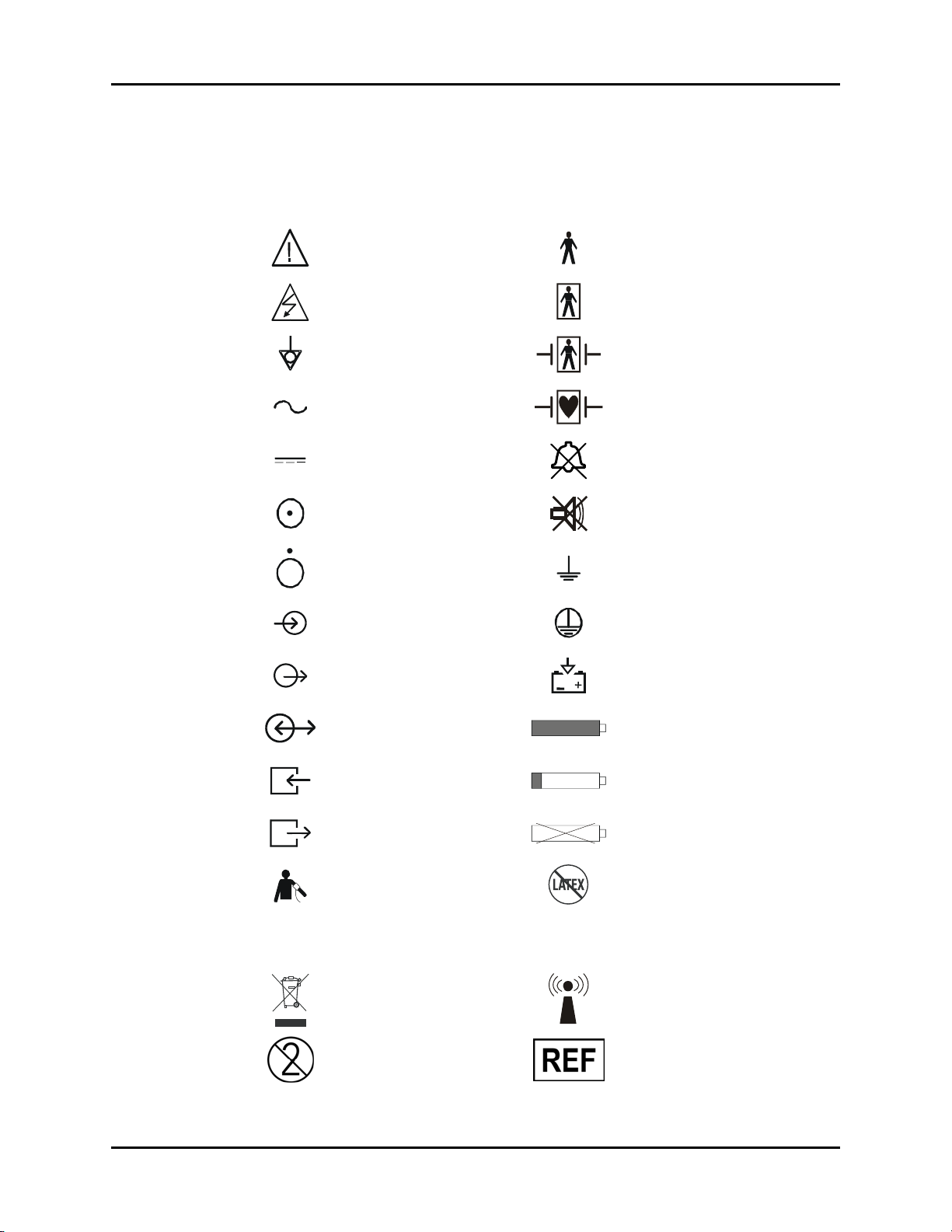
Symbols and Descriptions
SYMBOL DESCRIPTION SYMBOL DESCRIPTION
Attention, Consult
Accompanying Documents /
Refer to Manual
Dangerous Voltage Type BF Equipment
Type B Equipment
Equipotentiality
Alternating Current (AC)
Direct Current (DC) Alarm Off Icon
On (only for a part
of the equipment)
OFF (only for a part
of the equipment)
Data Input Protective Earth (Ground)
Data Output Battery Charging
Data Input / Output Full Battery
Gas Port Input Low Battery
Defibrillator Proof Type BF
Equipment
Defibrillator Proof Type CF
Equipment
Alarm Mute Icon
Earth (Ground)
Gas Port Output No Battery Present
NIBP Connection Latex-free product
Analog ECG and IBP output for
IABP
Passport 2®/Passport 2 LT™ Operating Instructions 0070-10-0649-01 xvii
communication to an IntraAortic Balloon Pump
Crossed out wheelie bin
indicates separate treatment
from general waste at end of
life
For single-patient use only, do
not reuse.
DEFIB
Analog ECG out and Sync Pulse for
connection to a defibrillator
Interference may occur in the
vicinity of equipment marked with
this symbol
Manufacturer’s reference/catalogue
number
Page 21

Introduction Symbols and Descriptions
For Neonatal use Manufacturer’s batch number
Not for Neonatal use Serial number
Conformité Européenne (CE)
Marking of Conformity to
European Medical Device
Directive. CE
represents the
XXXX
Software Version
Notified Body number
xviii 0070-10-0649-01 Passport 2®/Passport 2 LT™ Operating Instructions
Page 22
1.0
2
General Description
Passport
LEAD
SIZE
VIEW
NIBPECG
START
INTERVAL
STOP
Passport 2
ZERO
ALARMS DISPLAY
IBP
ALL
LIMITS
MUTE
MUTE
PRINT
STRIP
CONT
ECG
ALL
PRINT
TREND
STANDBY
DISCHARGE
MARK
EVENT
TRENDS
FREEZE
NORMAL
SCREEN
Passport 2®/Passport 2 LT™ Operating Instructions 0070-10-0649-01 1 - 1
Page 23

General Description
The Mindray DS Passport 2/Passport 2 LT is a vital signs monitor intended for
intrahospital use on human patients. The Passport 2 is a six (6) trace monitor, the
Passport 2 LT is a three (3) trace monitor. The unit has many features and functions, yet is
very easy to use through an integrated keypad, Navigator
™
Control Knob and intuitive menu
system. The patient parameters that can be monitored with the Passport 2/Passport 2 LT
are: ECG, Masimo SET
®
SpO2, Nellcor® Oxismart® or OxiMax® SpO2, Non-invasive
Blood Pressure, Respiration Rate and Temperature. Parameters optional for the Passport 2
are: 3 lead or 12 lead ST analysis with adjustable ISO and J points, Arrhythmia analysis,
Invasive Blood Pressure, Gases, Microstream
®
CO2 and 12 Lead ECG Interpretation.
The Passport 2/Passport 2 LT Monitor can be mounted on a rolling stand, a wall mount
bracket, gas machine arm, Bedrail or operated as a tabletop instrument. The Passport 2
monitor can be mounted to a Gas Module. The keypad contains dedicated primary
functions. The menu buttons provide access to setting up patient information, waveforms, and
parameters.
The Passport 2 comes with a color TFT LCD or a monochrome display. The Passport 2 LT
comes with a passive color or monochrome display. Digital displays are provided for Heart
Rate, Non-invasive Blood Pressure (NIBP), Pulse Oximetry (SpO
), Respiration Rate and
2
Temperature (T1). Additional digital areas present for the Passport 2 are Invasive Blood
Pressure (IBP1 and IBP2) (optional), Anesthetic Agents (optional), O
(optional), and CO
(optional). The optional built-in recorder provides hard copies of all
2
and NO2 (optional), ST
2
digital data and waveforms as well as Tabular Trend information.
The View 12™ ECG Analysis Module for the Passport 2 enables 12-Lead Acquisition,
Continuous 12-Lead ST Analysis and Arrhythmia Analysis with print capability. The View
™
12
ECG Analysis Module consists of a PCMCIA card for insertion into the Passport 2
with 12 Lead software, an M-12 cable and a detachable leadwire set.
The Passport 2 has the capability of interfacing with IABP Systems and Mindray DS’s
Central Stations, Gas Module, Remote Displays and Nurse Call Systems.
The Passport 2 LT has the capability of interfacing with IABP Systems and Mindray
DS's Remote Displays, and Nurse Call Systems.
The optional Gas Module can be used on an anesthesia cart or mounted on a rolling stand
or wall mounted.
The Passport 2/Passport 2 LT monitor is powered from an AC connection or internal
batteries. Batteries can be purchased separately as optional equipment. See Chapter 5.0.
The Passport 2/Passport 2 LT monitor can operate with either battery removed so that
fresh batteries can be installed during monitor operation.
1 - 2 0070-10-0649-01 Passport 2®/Passport 2 LT™ Operating Instructions
Page 24

General Description
Key features of the Passport 2/Passport 2 LT are:
• 3 or 5 Lead (I, II, III, aVR, aVL, aVF, V) ECG
• 12 Lead (I, II, III, aVR, aVL, aVF, V1, V2, V3, V4, V5, V6) ECG
(optional Passport 2)
• ECG Cascade
• ESIS Capability (3 or 5 Lead ECG only)
• 2 invasive blood pressure channels (optional Passport 2)
• 3 or 12 Lead ST Analysis with adjustable ISO and ST points
(optional Passport 2)
• Arrhythmia Analysis (optional Passport 2)
• 12 Lead ECG Interpretation (optional Passport 2)
• Non-invasive Blood Pressure (NIBP)
• Lead Selectable Impedance Respiration
•Masimo SET
®
SpO
2
• Nellcor® Oxismart® and OxiMax® SpO2 (optional)
• Microstream® CO2 (optional Passport 2)
• Gas Module Connectivity (optional Passport 2)
• 1 YSI 400/700 temperature channel
• Automatic sensor detection and waveform display
• Automatic Heart Rate source selection
•Auto-Set
™
Alarms
• Dual channel thermal array recorder (optional)
• Color TFT LCD display or Monochrome display (Passport 2)
• Monochrome display (Passport 2 LT)
• Battery operation (optional)
• Tabular 120 entries (500 entries optional)
• Graphic Trend display (Passport 2)
• Extended Trend Display, 500 entries (optional)
• OXY CRG display, 6 minutes (12 hours optional) (Passport 2)
• 6 trace erase bar refresh (Passport 2)
• 3 trace erase bar refresh (Passport 2 LT)
• Navigator
™
Control Knob
• Internal isolated power module
• External Remote Color Display Available with Color TFT LCD Equipped Monitor (optional
Passport 2)
• External Interfaces with IABP Systems and Mindray DS’s Central Stations, Gas Module,
Remote Displays, Nurse Call Systems and Serial Communications (Passport 2)
• External Interfaces with IABP Systems (Passport 2 LT)
Passport 2®/Passport 2 LT™ Operating Instructions 0070-10-0649-01 1 - 3
Page 25

General Description
• Communication with hospital CIS (Clinical Information Systems) through DIAP (Mindray
DS Improved ASCII Protocol, manual P/N 0070-00-0307) (Passport 2)
• Inter-Monitor Patient Data Transfer (with optional accessories)
• Inter-Monitor System Set-up Transfer (with optional accessories)
• Mounting Kits (optional accessory)
• Soft-Grip Handle
• Comm-Port (optional Passport 2)
• Dual PCMCIA Interface
1 - 4 0070-10-0649-01 Passport 2®/Passport 2 LT™ Operating Instructions
Page 26

2.0
Controls, Indicators and Connectors
This section of the Operating Instructions identifies and describes each control and display of
the Mindray DS Passport 2/Passport 2 LT Monitor.
Step-by-step instructions for operation of the monitor are provided in Section 3.0
“Operation”.
Passport 2®/Passport 2 LT™ Operating Instructions 0070-10-0649-01 2 - 1
Page 27
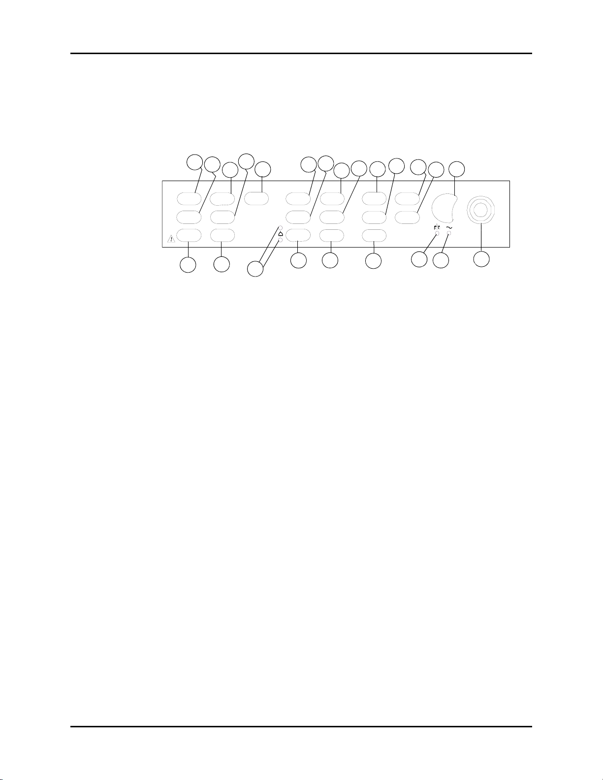
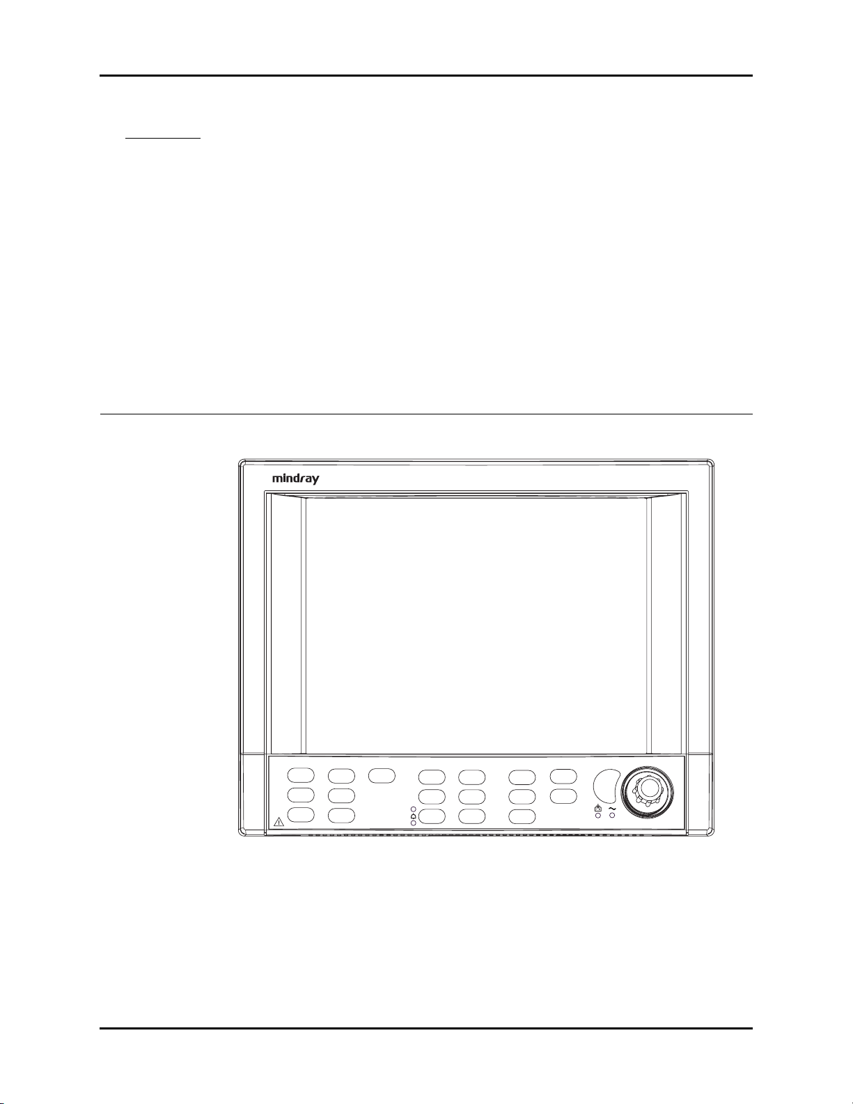
Front Panel Controls, Indicators and Connectors
2.1 Front Panel
The front panel keys are used to access many main functions quickly and easily.
Figure 2-1 below shows the keys and a brief explanation of each key.
5
IBP
ZERO
ALL
11
7
LIMITS
MUTE
MUTE
4
NIBPECG ALARMS PRINT
STARTLEAD
STOP
6
ALL
10
9
8
STRIP
CONT
ECG
PRINT
TREND
14
12
13
15
STANDBY
DISCHARGE
MARK
EVENT
17
16
DISPLAY
TREN DS
FREE ZE
18
21
19
NORMAL
SCREEN
22
20
23
SIZE
VIEW
3
1
2
INTERVAL
FIGURE 2-1 Front Panel Controls
1. (ECG) LEAD
Press this key to select the next ECG lead to display in waveform 1. Each time you press this
key, the next available ECG lead displays.
2. (ECG) SIZE
Press this key to select the next available Size of ECG for Waveform 1. Each time you press
this key, the next available ECG Size displays. When the largest ECG size is displayed, the
next key press displays the smallest size.
3. (ECG) VIEW
Press the VIEW key to see 6 leads of ECG at once when using the View 12™ ECG Analysis
Module or the 5 Lead ECG cable. With a View 12
™
ECG Analysis Module installed, press
the VIEW key once to see the first 6 leads of ECG, press again to view another 6 ECG
leads. Pressing a third time will return to normal display view. With a 5 lead ECG cable,
press the VIEW key once to see 6 leads of ECG, press again to return to normal display
view.
NOTE: Pressing the VIEW key does not affect the waveforms being
transmitted to the Central Station.
4. (NIBP) START
Press this key to begin an NIBP measurement or to begin or re-start automatic interval
measurements.
2 - 2 0070-10-0649-01 Passport 2®/Passport 2 LT™ Operating Instructions
Page 28

Controls, Indicators and Connectors Front Panel
5. (NIBP) INTERVAL
Press this key to modify the NIBP interval measurement time. The choices are: Off, Cont, 1
min, 2 min, 2.5 min, 3 min, 5 min, 10 min, 15 min, 20 min, 30 min, 1 hr, 2 hrs or 4 hrs. The
“Off” selection means that NIBP measurements can only be initiated manually. The “Cont”
selection means that measurements will be continuous (one right after the other). The
continuous measurement interval will only last for 5 minutes and then automatically change
to a 5 minute interval. The 1 minute interval will last for 10 minutes and then automatically
change to a 5 minute
6. (NIBP) STOP
Press this key to stop any NIBP measurement. If the interval mode is activated, pressing this
key disables the interval mode measurements. An NIBP Idle message displays until the
interval mode is restarted. If a Press STOP to clear. message is displayed, pressing this
key will clear a Cuff Overpressure condition.
7. (IBP) ZERO ALL
Press this key to set the current pressure of all the invasive pressure channels to zero provided
the channel(s) do not have an existing pressure being monitored. During the zeroing process,
the message Zeroing is displayed. The message Zero Complete displays when the
zeroing process is successful. If the zero process is not successful, the message Unable to
Zero is displayed. Available with Passport 2 monitor only.
8. (ALARMS) LIMITS
Press this key to display the Alarm menu. The Alarm menu provides you access to view or
change alarm values.
9. (ALARMS) MUTE ALL
Press this key to suspend audio alarms on all parameters. The alarms remain suspended for a
user selected amount of time. This amount of time is set in the Alarms Setup menu. While the
alarms are suspended, an Alarm Mute icon is displayed next to each silenced parameter.
Also, the message All Alarms Muted for XX:XX mins displays. XX:XX is the time
remaining in minutes and seconds. Press this key again during the suspended alarm time to
re-enable the audio alarm. If the suspend time was set to Permanent, the message All
Alarms Permanently Muted displays.
10. (ALARMS) MUTE
Press this key to suspend audio alarms on all currently alarming parameters. The alarms
remain suspended for a user selected amount of time as set in the Alarms Setup Menu or
when the alarm condition is no longer present. Any new alarms that occur while the alarm
tone is silenced will disable the silence and sound the alarm tone. While the alarms are
suspended, an Alarm Mute icon is displayed next to each silenced parameter.
11. (Alarms) LED Indicators
A set of 2 LED’s used to indicate that an alarm has been tripped. The WARNING (or Priority
1) LED is red and the CAUTION (or Priority 2) LED is yellow.
Passport 2®/Passport 2 LT™ Operating Instructions 0070-10-0649-01 2 - 3
Page 29

Front Panel Controls, Indicators and Connectors
12. (PRINT) STRIP
Press this key to initiate a 16 second print out of selected waveforms on the internal printer.
Press this key during the printing to stop the printer. With a View 12
™
ECG Analysis Module
installed, press the VIEW key, then press the STRIP key to initiate a 12-lead Interpretative
report that will be printed at either the internal recorder or a laser printer. If the print
destination is a remote Central Station, then pressing this key will initiate a printout at the
Central Station.
13. (PRINT) CONT ECG
Press this key to initiate a continuous ECG 1 and 2 waveform printout on the internal printer.
Press this key during the printing to stop the printer.
14. (PRINT) PRINT TREND
Press this key to initiate the printing of the desired trend. By default, the monitor’s stored trend
information will be printed by the internal printer. Press this key during the printing to stop the
printer.If the print destination is a remote Central Station, then pressing this key will initiate a
trend report at the Central Station.
15. STANDBY
Press this key to place the Passport 2/Passport 2 LT into a STANDBY mode. While in
STANDBY mode, monitoring is discontinued and the alarms are in permanent suspension,
interval NIBP measurements are placed in idle mode, CO
pump is shut off, and the display
2
shuts down. When in the STANDBY mode, the message STANDBY. TO BEGIN
MONITORING, PRESS STANDBY is displayed. Press the STANDBY key again to exit
the STANDBY mode and return to the normal screen.
NOTE: Trend data is not cleared in the STANDBY mode. When the
STANDBY mode is released, NIBP INTERVAL is in IDLE MODE
and requires re-activation via the START key. The CO
automatically reactivates if the Microstream® sensor is in
place.
pump
2
16. DISCHARGE
Press this key to initiate the process of discharging the patient from the monitor. A menu titled
Patient Discharge will be displayed. Depending on the monitor’s configuration, the
Normal Screen menu choice will be provided along with one or more of the following
selections: Discharge From Monitor, Discharge From Central and Discharge
From Both. If any discharge option is selected, a confirmation box will be displayed.
(Discharging a patient from the monitor deletes all patient trend and demographic data and
places the monitor in STANDBY mode.) An onscreen message will display as follows:
• For Main Module Software Versions Y.xx and earlier, the message STANDBY. TO
BEGIN MONITORING, PRESS STANDBY is displayed.
• For Main Module Software Versions AA.xx and later, the message PATIENT
DISCHARGED. MONITOR IN STANDBY MODE - TO BEGIN MONITORING,
PRESS STANDBY is displayed.
Upon exiting STANDBY mode, the monitor configuration reverts to currently saved settings.
Selecting Normal Screen from the menu aborts the discharge.
2 - 4 0070-10-0649-01 Passport 2®/Passport 2 LT™ Operating Instructions
Page 30

Controls, Indicators and Connectors Front Panel
17. MARK EVENT
Press this key to cause a time stamp event marker to be noted in the trend memory. If
connected to a Panorama Central Station, a time stamp event marker will also be noted in
the Central Station’s trend memory.
18. (DISPLAY) TRENDS
Press this key to display the List Trend screen. Press this key a second time to display the
Graph Trend screen. Press this key a third time to return to the Normal Display. If Neonate or
Pediatric is selected as the patient size, a third press will display the OXY CRG display. A
fourth press will then return the monitor to normal display.
19. (DISPLAY) FREEZE
Press this key to freeze the waveform display. When waves are frozen, the message WAVES
FROZEN is displayed. Digital data will continue to be updated.
20. NORMAL SCREEN
Press this key at any time to return the screen to the normal monitoring mode. All menus are
closed.
21. Battery Charging LED
A green LED located below the battery icon indicates that the battery charger is active. The
charger will not always be active when AC power is present. It is dependent on the battery
type (sealed lead acid vs. lithium-ion) and battery charge condition. The LED is not an
indication of the condition of the batteries or their charge level. Charged batteries must be
installed in the monitor to ensure uninterrupted operation while switching from AC to battery
power.
22. AC Power LED
A green LED beside the Battery Charging LED that is used to indicate that the unit is
connected to the AC Power within the facility.
23. Navigator
™
Control Knob
Rotate this knob to highlight the various menus on the display. Press the center of the knob to
display the highlighted menu. Once a menu is displayed, rotate the knob to highlight the
items within the menu. Press the center of the knob to select a highlighted item.
Passport 2®/Passport 2 LT™ Operating Instructions 0070-10-0649-01 2 - 5
Page 31

Display Controls, Indicators and Connectors
2.2 Display
The display of the Passport 2/Passport 2 LT provides menus, waveforms, parameter
information, and messages. Figure 2-2 below shows the layout of the screen. The display can
be a color LCD or monochrome flat panel for the Passport 2 monitor. The display for the
Passport 2 LT is a monochrome panel. The number of waves displayed can vary from 3 to
6 (Passport 2 LT is limited to 3). The default operation follows these basic rules:
a. If a wave and related parameter tile are displayed, they are horizontally linked and
have the same color for easy and clear reading. The ECG parameter may violate
this rule since multiple vectors can be viewed at one time.
b. NIBP and Temperature data is displayed only in the lower row of boxes. With the
Passport 2 monitor, as the fourth, fifth and sixth waves are sensed they will
automatically insert and fill the bottom waveform areas.
c. Font size for parameter data vary with the amount of data on the screen to maximize
the size of the numbers.
The monitor also includes a display set-up function that allows the user to customize the
display. User preferred set-ups can be programmed and saved.
24
Waveform
Area
mmHg
T1
NIBP: Idle
25
Parameter Menu
Headings
Menu Headings
27
Des% O2% N2O%
Insp
4.0 48 60
Exp
F
1.1 46 58
26 28
Parameter
Areas
ParametersPri nt Set upMonitor Setup FunctionsPat ien t
07/27/04 6:55 PM
LASTNAME, FIRST Adu lt
HR
Lead mm
Insp
Ex p
120
Battery
Indicator
II
I
V
80
29
Radio
Icon
bpm
P
A
S
PV C/m in: 45
Source: A uto
+2.2
-2.1
-3.0
bpm
PR
%
rpm
14
So ur ce: CO2
mmHg
mmHg
(100)
Interval: ON
ET: 13 min
30
Panorama
Icon
170
55
OFF
94
FIGURE 2-2 Display
2 - 6 0070-10-0649-01 Passport 2®/Passport 2 LT™ Operating Instructions
Page 32

Controls, Indicators and Connectors Display
24. Waveform Area
The waveform area is used to display the windows that contain parameter waveforms. Up to
6 waveforms can be displayed. The top window is always set to display the ECG waveform
and cannot be changed. By default, SpO
(Pleth) will appear as the second waveform, if
2
connected. Respiration or CO2 will appear as the third waveform. If pressure transducers are
plugged into IBP connectors, the screen will reformat to display additional waveforms, and
IBP will appear as the fourth and fifth waveforms. Except for the top window that is reserved
for ECG, the windows can be changed to display any of the available parameters and
waveforms. Each window contains a menu heading, which can be selected with the
Navigator
™
Control Knob.
25. Parameter Menu Heading
™
Using the Navigator
Control Knob, select a parameter menu heading, change the
waveform and / or set specific information for the parameter. See the next section for a
description of each menu.
26. Parameter Area
The parameter areas contain the digital data for each available parameter.
27. Menu Headings
Using the Navigator
™
Control Knob, select a menu to set or review specific information. See
the next section for a description of each menu.
28. Battery Indicator
When batteries are installed and the monitor is functioning on battery power, the battery
indicator provides a visual reference for the approximate charge level of the batteries. See
the following examples.
Full Battery Low Battery No Battery Present
(Lithium-Ion batteries only)
If the monitor is configured for lithium-ion batteries, when there are no batteries installed, the
battery indicator will be displayed with an “X” through it as shown in the example.
When the battery charge is low, but not below the cutoff voltage, the battery indicator will
begin to flash and a low pitched double beep will be generated every minute.
NOTE: When the battery indicator begins to flash, less than 15
minutes of operating time remains, depending upon the
number of functions that are operational.
NOTE: The internal recorder may not be operational when the
Passport 2®/Passport 2 LT™ Operating Instructions 0070-10-0649-01 2 - 7
battery charge is low.
Page 33

Display Controls, Indicators and Connectors
29. Radio Icon
If a Panorama Instrument Radio - 608 is installed and “WMTS Enabled” is set to “Yes” (in the
Installation Menu), this icon will be displayed.
30. Panorama Icon
1 Vor
This icon will display in one of two possible formats as follows:
•If the Passport 2 608 radio is sending data but it is not being displayed at a
Panorama Central Station, then this icon will display the number “1”.
•If the Passport 2 data is being displayed at a Panorama Central Station, then this
icon will display the capital letter “V”.
2 - 8 0070-10-0649-01 Passport 2®/Passport 2 LT™ Operating Instructions
Page 34

Controls, Indicators and Connectors Menus
2.3 Menus
The Main Menu system of the Passport 2/Passport 2 LT is available through the Menu
headings, which are always displayed on the screen. The headings are accessed using the
Navigator
time. When the Menu heading that you would like to access is highlighted, press the center
of the Control Knob to display the menu. Turn the Control knob again to highlight items
within the Menus headings and press the Control Knob to select the highlighted item. If
selecting the highlighted item displays more selections, continue using the Control Knob in
the same manner (turn to highlight, press to select) to set the options as desired. The Menu
headings are:
2.3.1 Patient
™
Control Knob. Turning the Control Knob highlights the Menu headings one at a
FIGURE 2-3 Patient Menu
NOTE: Changes that are made in the Patient Menu do not become
Passport 2®/Passport 2 LT™ Operating Instructions 0070-10-0649-01 2 - 9
effective until the menu is closed.
Page 35

Menus Controls, Indicators and Connectors
Patient
MENU ITEM SELECTIONS DEFAULT/COMMENTS
Patient Size Adult, Pediatric,
Neonate
Gender Unspecified, Male,
Female
Date of Birth Default is Unspecified. Use Navigator Control Knob to
Last Name A keyboard displays. Use the NavigatorTM Control
First Name A keyboard displays. Use the NavigatorTM Control
1
ID #
2
Bed #
Height 8" to 120"
(20 cm to 305 cm)
Weight 0.1 lbs to 1100 lbs
(0.1 kg to 500 kg)
Admit Patient
3
Yes, No Default is No. Select Yes to admit patient to the central
1 The “ID #” field can accept a maximum of 15 characters. If a Passport 2 608 radio is communicating
with a Panorama Central Station, only the first 10 characters will be displayed in the “ID” field at the
Central Station.
2 The “Bed #” field can accept a maximum of 15 characters. However, since only the first 5 characters will
be displayed in the “Bed” field at a Panorama Central Station if a Passport 2 608 radio is communicating
with the Central Station, the following standard format for this demographic is recommended:
Adult
Default is Unspecified. Use Navigator Control Knob to
select patient’s gender.
select patient’s date of birth.
Knob to enter the patient’s LAST name.
Knob to enter the patient’s FIRST name.
A keyboard displays. Use the NavigatorTM Control
Knob to enter the patient’s ID #.
A keyboard displays. Use the NavigatorTM Control
Knob to enter the patient’s Bed #.
Adult - 70"
Pediatric - 30"
Neonate - 20"
Adult - 150 lbs
Pediatric - 15 lbs
Neonate - 6 lbs
station.(This selection appears only when connected to
a VISA or PatientNet
®
Central Station.)
• Start the string with a room # that has a fixed number of digits. For example, if
the maximum number of digits that is used in numbering the rooms is 4, then for
room 102, a leading zero would be added to get the 4th digit - 0102.
• Follow the room # with a letter to identify the particular bed within the room. For
example, a room with 2 beds would have bed A and bed B.
• An example of a complete “Bed #”: Bed B in room 513 (in a facility where the
maximum number of digits that is used in numbering the rooms is 4) would be
identified as 0513B.
NOTE: If the monitor is communicating with the EMR (Electronic Medical Records) system through a Pan-
orama Gateway, any changes to patient demographics made at the monitor will not be sent to the
EMR system. For further explanation, refer to section 3.26, “Connection to Panorama• Gateway”.
3 Passport 2 only.
2 - 10 0070-10-0649-01 Passport 2®/Passport 2 LT™ Operating Instructions
Page 36

Controls, Indicators and Connectors Menus
2.3.2 Monitor Setup
FIGURE 2-4 Monitor Setup
Monitor Setup Menu
MENU ITEM SELECTIONS FACTORY DEFAULT/COMMENTS
Normal Screen Select to return to normal screen.
Save Current A confirmation prompt appears. Select Yes to save
Display Setup Open an additional menu which allows you to
View ECG Setup Open an additional menu which allows you to
Rescale Waves Select to auto-scale all waveforms.
Alarm Volume Variable from
Minimum to
Maximum
Beep Volume Variable from Off to
Maximum
ECG Speed 6.25, 12.5, 25,
50 mm/sec
IBP Speed 6.25, 12.5, 25,
50 mm/sec
* Passport 2 only.
the current settings as the “monitor” defaults.
change the positions of the parameters and
waveforms.
change the ECG leads viewed when you press the
VIEW key.
Mid-Scale / Displays a slide bar to adjust the setting
of the alarm volume. Use the Navigator
Knob to adjust the volume.
Mid-Scale / Displays a slide bar to adjust the setting
of the systole beep volume. Use the Navigator
Control Knob to adjust the volume.
25 mm/sec / Select to change trace speed of ECG &
Pleth waveforms.
25 mm/sec / Select to change trace speed of
pressure waveforms.
™
Control
™
Passport 2®/Passport 2 LT™ Operating Instructions 0070-10-0649-01 2 - 11
Page 37

Menus Controls, Indicators and Connectors
Monitor Setup Menu (Continued)
MENU ITEM SELECTIONS FACTORY DEFAULT/COMMENTS
Resp/Gas Speed 3.125, 6.25, 12.5,
25 mm/sec
Advanced Setup Select to set these menu items:
* Passport 2 only.
12.5 mm/sec / Select to change trace speed.
•Set Date
•Set Time
•Trend Interval
•NIBP Trend
•Alarm Trend
•Nurse Call*
• Arrhythmia Menu*
• NIBP Start Mode
•Apnea Latch
Advanced Setup Menu
MENU ITEM SELECTIONS FACTORY DEFAULT/COMMENTS
Previous Menu Select to return to previous menu.
Set Date Select to change date. Changing the date will clear
the trend information. A confirmation message will
display.
Set Time Select to change time. Changing the time will clear the
Trend Interval Off, 1, 2.5, 5,10,
15, 20, 30 min,
1 hr, 2 hrs
NIBP Trend On, Off On / Select to save numeric data to trend on NIBP
Alarm Trend On, Off Off / Select to save numeric data to trend on Alarms.
Nurse Call Off, 1 second,
Continuous
Arrhythmia Menu* This selection will open the Arrhythmia Menu.
NIBP Start Mode Interval Mode, Timer
Mode
Apnea Latch On, Off On / Select to turn apnea alarm latching on or off.
* Passport 2 only.
trend information. A confirmation message will
display.
Off / Select to change time of trend data collection.
measurements.
Off / Select to choose the Nurse Call activation time.
Interval Mode / Select the Interval mode to
synchronize NIBP start with the integral clock. Select
Timer Mode to synchronize NIBP start with the interval
selected in relation to the real time clock.
2 - 12 0070-10-0649-01 Passport 2®/Passport 2 LT™ Operating Instructions
Page 38

Controls, Indicators and Connectors Menus
Arrhythmia Menu (Optional)
MENU ITEM SELECTIONS
Previous Menu Use Navigator™ Control knob to
Arrhythmia All On, All Off,
Non-lethals Off
Irregular HR** On, Off Factory default is On. Use Navigator
V-Tach Threshold 3 to 15 beats Factory default is 3 beats. Use
V-Tach Rate 100 to 180 bpm Factory default is 120 bpm. Use
Asystole Delay 3 to 10 seconds (3/5 lead)
3 to 8 seconds (12 lead)
Relearn Use Navigator Control knob to select
ECG Noise Delay** 3 to 30 seconds Factory default is 5 seconds. Use
** Only available with 3-lead or 5-lead.
FACTORY DEFAULT/
COMMENTS
return to the previous menu.
Factory default is All On. Use
Navigator Control knob to turn
arrhythmia analysis on or off.
Control knob to turn Irregular HR on
or off.
Navigator Control knob to select
how many ventricular beats in a row
will constitute V-Tach.
Navigator Control knob to select the
heart rate threshold which must be
reached to constitute V-Tach.
Factory default is 4 seconds. Use
Navigator Control knob to select the
number of seconds with an absence
of an R wave that will constitute
asystole.
to relearn Arrhythmia and ST.
Navigator Control knob to select the
number of seconds to delay the ECG
Noise Alarm.
Passport 2®/Passport 2 LT™ Operating Instructions 0070-10-0649-01 2 - 13
Page 39

Menus Controls, Indicators and Connectors
2.3.3 Print Setup
FIGURE 2-5 Print Setup
Print Setup Menu
MENU ITEM SELECTIONS DEFAULT/COMMENTS
Waveform 1 ECG 1-6, IBP1,* IBP2,*
Pleth, Resp, CO2,* O2,*
Agent,* N2O*
Waveform 2 Off, ECG 1-6, IBP1,*
Select Printer Local, Remote, Local &
Print on alarm Yes, No No / Select to print data on an alarm
Format Leader, Wave Leader / Select to format strip with all digital
Print Every Off, 1, 5, 10, 15, 20, 30,
Average ST Complex** This selection will print the Average ST
* Passport 2 only.
** Passport 2 only with View 12
IBP2,* Pleth, Resp, CO
O
* Agent,* N2O*
2,
Remote, Local & Laser**,
Laser & Remote**, Laser**
minutes, 1 hr, 2 hrs
™
ECG Analysis Module.
ECG 1 / Select to choose Waveform 1 on the
printer.
ECG 2 / Select to choose Waveform 2 on the
printer.
*
2,
Select printer source for printing waveforms /
trends. A default printer or combination of
printers can be set.
occurrence.
data in the leader or top / bottom of wave.
Off / Select to set a time interval for automatic
printing.
Complex for this patient to the Local Printer.
2 - 14 0070-10-0649-01 Passport 2®/Passport 2 LT™ Operating Instructions
Page 40

Controls, Indicators and Connectors Menus
2.3.4 Parameters
FIGURE 2-6 Parameters
Parameters Menu
MENU ITEM DEFAULT/COMMENTS
ECG
ST*
NIBP
IBP1*
IBP2*
SpO
2
CO
2*
Resp
Gases*
Temp era tu re
* Passport 2 only.
Select to open the respective menu. These can also be selected
through the individual parameter menus.
Passport 2®/Passport 2 LT™ Operating Instructions 0070-10-0649-01 2 - 15
Page 41

Menus Controls, Indicators and Connectors
2.3.5 Functions Menu
FIGURE 2-7 Functions Menu
Functions Menu
MENU ITEM SELECTIONS DEFAULT/COMMENTS
Normal Screen Select to return to normal screen
Copy patient data to
card
Copy patient data from
card
12-Lead ECG* Disable / Enable Use Navigator Control knob to disable or
* Passport 2 only with View 12
“System Information” menu, 12-Lead ECG will not be listed as a choice in the Functions Menu.
™
ECG Analysis Module. NOTE: If “Enable Network” is set to “Wireless” in the
Select to copy the patient data to a data
transfer card.
Select to copy the patient data from a data
transfer card.
enable 12-Lead ECG.
2 - 16 0070-10-0649-01 Passport 2®/Passport 2 LT™ Operating Instructions
Page 42

Controls, Indicators and Connectors Left Side Panel
2.4 Left Side Panel
CO2 Output CO2 Input
31
T1 IBP 1 IBP 2
32
33
34
35
36
37
FIGURE 2-8 Left Side Panel
39
SpO2
ECG
38
31. CO
Exhaust Connector (Optional Passport 2)
2
This connector is used to attach an exhaust line which can be used to connect to a gas
scavenger system.
32. T1 Connector
A standard three wire phone jack used to mate with either the YSI series 400 or 700
temperature probes. The monitor automatically detects which probe is connected.
33. IBP 1 Connector (Optional Passport 2)
A six-pin male connector used for Channel 1 Pressure Transducer connection. Mindray DS
specified pressure transducers are listed in Chapter 5, Accessories.
34. IBP 2 Connector (Optional Passport 2)
A six-pin male connector used for Channel 2 Pressure Transducer connection. Mindray DS
specified pressure transducers are listed in Chapter 5, Accessories.
Passport 2®/Passport 2 LT™ Operating Instructions 0070-10-0649-01 2 - 17
Page 43

Left Side Panel Controls, Indicators and Connectors
35. SpO2 Connector
A 14-lead Mini-D ribbon type female connector used to attach the SpO
sensor to the
2
monitor. See Chapter 5 for the complete listing of approved SpO2 accessories.
36. Battery Compartment
This compartment houses the two optional, user replaceable, rechargeable batteries (sealed
lead acid or lithium-ion). These batteries provide power to the unit when it is not connected to
an AC receptacle. The batteries can be independently removed and replaced while the unit
is operating.
37. NIBP Rectus Connector
This connector is used to attach the NIBP hose to the unit.
38. ECG Connector
This connector is used to attach ECG cables. Use Mindray DS cables listed in Chapter 5.0,
Accessories.
39. CO
Input Connector (optional Passport 2)
2
This connector is used to attach the Microstream® CO2 FilterLine®, listed in Chapter 5.0,
Accessories, to the unit.
2 - 18 0070-10-0649-01 Passport 2®/Passport 2 LT™ Operating Instructions
Page 44

Controls, Indicators and Connectors Right Side Panel
2.5 Right Side Panel
44
40
41
42
43
FIGURE 2-9 Right Side Panel
40. PCM1 and PCM2 Card Slots
These sockets are used for extended trend memory, software download to the CPU, patient
™
data transfer, monitor set-up transfers, View 12
ECG Analysis Module and Panorama
Instrument Radio - 2.4.
41. Power Switch
A momentary switch that turns power ON or puts the unit in STANDBY but does not prevent
charging of the batteries. Press the top of the switch once to turn the unit ON. Press the top of
the switch again to turn the unit OFF.
42. DEFIB Connector
Used to connect a defibrillator sync cable.
43. IABP Connector
Used for triggering an Intra-Aortic Balloon Pump from the Passport 2/Passport 2 LT ECG
signal only when using a 3-lead or 5-lead ECG cable.
44. Recorder (Optional)
A two trace thermal strip chart recorder with integral paper spool.
Passport 2®/Passport 2 LT™ Operating Instructions 0070-10-0649-01 2 - 19
Page 45

Rear Panel Controls, Indicators and Connectors
Mindray DS USA Inc.. Paramus, NJ 07652 USA
V 100-120
~
/ 220-240
~
A .75 / .35
Hz 60 / 50
¨
4,621,643
4,700,708
4,770,179
4,869,254
4,653,498
4,911,167
4,928,692
4,934,372
This product may be
protected under one or
more of the following
U.S. patents:
5,078,136
5,368,224
5,482,036
5,490,505
5,632,272
5,685,299
5,758,644
5,769,785
IEC 601-1:1988
CSA - C22.2 No. 601.1 - M90
UL 2601-1:1997
S/W
P/N
S/N
Passport
2
™
8 88 8- 00 - 1 2 3 4 -1 2 3 4 5
8 88 8- 00 - 1 2 3 4 -1 2 3 4 5
8 88 8- 00 - 1 2 3 4 -1 2 3 4 5
Model No. D T-500 0 FCC I D:BQI 95DT- 5000
This Device Complies With Part 15 Of The FCC Rules.
Operation Of This Device Is Subject To The Following
Two Conditions: (1) This Device May Not Cause Harmful
Interference, And (2) This Device Must Accept Any
Interference That May Be Received, Including
Interference That May Cause Undesired Operation.
2.6 Rear Panel
47
49
Passpo
Model No. DT-5000 FCC ID:BQI95DT-5000
This Device Complies With Part 15 Of The FCC Rules.
Operation Of This Device Is Subject To The Following
Two Conditions: (1) This Device May Not Cause Harmful
Interference, And (2) This Device Must Accept Any
Interference That May Be Received, Including
46
45
V 100-120
/ 220-240
A .75 / .35
Hz 60 / 50
This product may be
protected under one or
more of the following
U.S. patents:
4,621,643
4,700,708
4,770,179
4,869,254
4,653,498
4,911,167
4,928,692
4,934,372
5,078,136
5,368,224
5,482,036
5,490,505
5,632,272
5,685,299
5,758,644
5,769,785
Interference That May Cause Undesired Operation.
S/W
P/N
S/N
Mindray DS USA Inc.. Paramus, NJ 07652 USA
IEC 601-1:1988
CSA - C22.2 No. 601.1 - M90
UL 2601-1:1997
48
FIGURE 2-10 Rear Panel
45. AC Receptacle
Insert an AC power cord into this connector.
CAUTION: Use only Mindray DS supplied power cords, or if a substitute is
necessary, use only hospital grade power cords.
46. Equipotential lug
Provides Equipotential grounding of hospital equipment
47. Soft Grip Handle
Use for carrying the monitor.
48. Main I/O Connector Port (DM1)
Area dedicated for the use of an optional communication port.
2 - 20 0070-10-0649-01 Passport 2®/Passport 2 LT™ Operating Instructions
49. Expansion Slot
Used for connecting an optional Panorama Instrument Radio - 608.
Page 46

Controls, Indicators and Connectors Remote Color Display (Passport 2 Only)
2.7 Remote Color Display (Passport 2 Only)
Passport 2 (with Comm Port), rear view
Remote Color Display, rear view
1. Connect Interface Cable
to the Analog Input
Connector on the Remote
Color Display.
FIGURE 2-11 Remote Color Display
NOTE: Passport 2 monitors equipped with EL (electro-luminescent)
displays do not support remote display capabilities.
For instructions on mounting the remote display to a wall, see the Passport 2 Service
Manual, Installation Guide.
Remote Color Display Interface Cable
2. Connect Passport 2
Monitor Remote Color
Display interface cable.
Passport 2®/Passport 2 LT™ Operating Instructions 0070-10-0649-01 2 - 21
Page 47

Gas Module (Optional Passport 2) Controls, Indicators and Connectors
8
0
40
0
mmHg
40
10
- 1
+ 1
mV
D
A
P
S
2.8 Gas Module (Optional Passport 2)
NOTE: The following models are referenced in this manual: Gas
Module II, Gas Module SE, and Gas Module 3. When
information is common to all models, the generic name
“Gas Module” is used. Information that is unique to a
specific model is identified accordingly.
2.8.1 Gas Module II and SE
2.8.1.1 Front Panel
Passpo rt® 2
TrendAlarmsMonitor Setup RecordPatient/ADT
+ 1
mV
- 1
40
10
40
mmHg
ALARMS
LIMITS
MUTE
ALL
MUTE
Insp Exp
A
G
O
41
36
2
T
7.6
Des
1
5.2
51
O
N
54
2
PRINT
STRIP
CONT
ECG
PRIN
T
TREN
D
T1
T
E
M
C
36.7
P
ECG
NIBP
IBP
INTERVAL
ZERO
STAR
T
ALL
STOP
LEAD
SIZE
VIE
W
%
%
%
DISCHARGE
STANDBY
EVEN
MAR
Juan Valdez /Room 1420 / BED 2
HR
E
C
G
S
T
RPM
R
E
S
P
C
0
2
S
P
0
2
Sys
N
I
B
P
DISPLAY
TRENDS
FREEZE
K
T
11/9/98 10:28 am
125
PVC/min: 45
Source: Auto
18
Source: ECG
ExpInsp
1
/38
RR (CO2 )
%
98
120 80
/
Mean (93)
Interval: ON ET: 13min
NORMA
REEN
SC
Lead mm
II
aVR
V1
ST Pt: 80/60
mmHg
14 rpm
PRSpO2
81
Dia
L
+2.2
-2.1
-3.0
bpm
Gas Module SE™
51
55
50
52
53
54
FIGURE 2-12 Gas Module II and SE - Front Panel
50. Input Port
This port is used to connect the sampling tubing to the Gas Module.
51. Water Trap Assembly (includes Water Trap Reservoir)
The Water Trap Assembly (P/N 0202-00-0129) is used to capture moisture drawn in with
the patient sample. The Water Trap Reservoir must be emptied and rinsed (with water only)
whenever more than half full or whenever changing patients. Refer to Section 4.9 for more
details.
52. Dust Filter
The Dust Filter (P/N 0378-00-0040) protects the Gas Module from airborne dust. It should
be removed and cleaned on a regular basis. Refer to Section 4.9 for more details.
2 - 22 0070-10-0649-01 Passport 2®/Passport 2 LT™ Operating Instructions
Page 48

Controls, Indicators and Connectors Gas Module (Optional Passport 2)
Mindray DS USA Inc. Mahwah, NJ 07430 USA
V 100-120~ / 220-240
~
A .75 / .35
Hz 60 / 50
This product may be
protected under one or
more of the following
U.S. patents:
4,621,643
4,700,708
4,770,179
4,869,254
4,653,498
4,911,167
4,928,692
4,934,372
5,078,136
5,368,224
5,482,036
5,490,505
5,632,272
5,685,299
5,758,644
5,769,785
IEC 601-1:1988
CSA - C22.2 No. 601.1 - M90
UL 2601-1:1997
S/W
P/N
S/N
Model No. D T-5000 F CC ID: BQI95 DT-500 0
This Device Complies With Part 15 Of The FCC Rules.
Operation Of This Device Is Subject To The Following
Two Conditions: (1) This Device May Not Cause
Harmful Interference, And (2) This Device Must
Accept Any Interference That May Be Received, Including
Interference That May Cause Undesired Operation.
8888-00 -1234-12345
8888-00 -1234-12345
8888-00 -1234-12345
¨
NC1 SP1RD1
Mindray DS USA Inc.
2
53. Dust Filter Cover
The Dust Filter Cover is removed to access the filter.
54. Power Indicator Lamp
This lamp illuminates when the Power Switch is in the ON position.
55. Power Switch
A switch used to power the unit ON and OFF. It is located on the front of the Gas Module SE
and on the back of the Gas Module II.
2.8.1.2 Rear Panel
60
56
FIGURE 2-13 Gas Module II and SE - Rear Panel
56. AC Power Input
This input is used to attach the special “Y” Shaped Power Cord.
Passport
57
TM
59
58
57. Exhaust Port
This panel mount coupling is used for attaching a gas scavenging system (P/N 0997-000923 or P/N 0997-00-0984) to the Gas Module.
Passport 2®/Passport 2 LT™ Operating Instructions 0070-10-0649-01 2 - 23
Page 49

Gas Module (Optional Passport 2) Controls, Indicators and Connectors
2
58. Reference Port
This port is used only to measure room air. This port is not to be connected to anything. Do
not block this port.
59. External Interface Port
A communication interface port used to connect the Gas Module to the Passport 2.
60. Equipotential lug
Provides Equipotential grounding of hospital equipment
2.8.2 Gas Module 3
2.8.2.1 Front Panel
®
2
Passport
62
64
61
63
FIGURE 2-14 Gas Module 3 - Front Panel
61. Input Port
This port is used to connect the sampling tubing to the Gas Module.
62. Water Trap Assembly (includes Water Trap Reservoir)
The Water Trap Assembly (Adult/Pediatric P/N 0202-00-0182-10, Neonate P/N 0202-000181-10) is used to capture moisture drawn in with the patient sample. The Water Trap
Reservoir must be emptied and rinsed (with water only) whenever more than half full or
whenever changing patients. Refer to section 4.9 for more details.
2 - 24 0070-10-0649-01 Passport 2®/Passport 2 LT™ Operating Instructions
Page 50

Controls, Indicators and Connectors Gas Module (Optional Passport 2)
2
63. Power Indicator Lamp
This lamp illuminates when the Power Switch is in the ON position.
64. Power Switch
A switch used to power the unit ON and OFF.
2.8.2.2 Rear Panel
TM
Passport
Model No. DT-5000 FCC ID:BQI95DT-5000
This Device Complies With Part 15 OfThe FCC Rules.
Operation OfThis Device Is SubjectTo The Following
Two Conditions: (1)This Device May Not Cause
Harmful Interference,And (2)This Device Must
5,078,136
5,368,224
5,482,036
5,490,505
5,632,272
5,685,299
5,758,644
5,769,785
~
AcceptAny InterferenceThat May Be Received, Including
InterferenceThat May Cause Undesired Operation.
S/W
8888-00- 1234-12345
P/N
8888-00- 1234-12345
S/N
8888-00- 1234-12345
Mindray DS USA Inc., Mahwah, NJ 07430 USA
IEC 601-1:1988
¨
CSA - C22.2 No. 601.1 - M90
UL 2601-1:1997
V 100-120~/ 220-240
A .75 / .35
Hz 60 / 50
This product may be
protected under one or
more of the following
U.S. patents:
4,621,643
4,700,708
4,770,179
4,869,254
4,653,498
4,911,167
4,928,692
4,934,372
NC1 SP1RD1
Mindray DS USA Inc.,
68
65
67
66
FIGURE 2-15 Gas Module 3 - Rear Panel
65. AC Power Input
This input is used to attach the special “Y” Shaped Power Cord.
66. Exhaust Port
This panel mount coupling is used for attaching a gas scavenging system
(P/N 0997-00-0923 or P/N 0997-00-0984) to the Gas Module.
67. External Interface Port
A communication interface port used to connect the Gas Module to the Passport 2.
68. Equipotential lug
Provides Equipotential grounding of hospital equipment.
Passport 2®/Passport 2 LT™ Operating Instructions 0070-10-0649-01 2 - 25
Page 51

Comm-Port (Optional Passport 2) Controls, Indicators and Connectors
2.9 Comm-Port (Optional Passport 2)
NOTE: Figures 2-17 to 2-20 depict four distinct sub-models of the
Comm-Port that have different interface capabilities. Only
one sub-model at a time can be connected to the Passport 2.
69
Main I/O Connector
FIGURE 2-16 Comm-Port Main Connector
69. Comm-Port to Main I/O Connector (DB1)
This is the female connector that will engage the equivalent male connector when connected
to the Passport 2.
!
CS1 MB1 RD1
70
FIGURE 2-17 Comm-Port 2
70. Ethernet Connector (CS1)
Ethernet connection port used for networking connections or devices requiring ethernet
communication such as the Panorama™ Central Station or a Laser Printer.
71
73
71. Module Bus Connector (MB1)
Port used to connect to future enhancements.
72. Serial Port Connector (SP1 or SP2)
Proprietary serial port used to connect to the Visa or Patient Net Central Station, Gas
Module, or other devices.
2 - 26 0070-10-0649-01 Passport 2®/Passport 2 LT™ Operating Instructions
Page 52

Controls, Indicators and Connectors Comm-Port (Optional Passport 2)
SP1NC1RD1
73
74
72
FIGURE 2-18 Comm-Port 3
73. Remote Display Connector (RD1)
Port used to connect a color remote display to the Passport 2 monitor
74. Nurse Call Connector (NC1)
Port used to connect a Nurse Call Cable to the Passport 2 monitor
LINKTX
CS1 MB1 SP1
70
FIGURE 2-19 Comm-Port 4
71
72
SP2NC1SP1
72
FIGURE 2-20 Comm-Port 5
Passport 2®/Passport 2 LT™ Operating Instructions 0070-10-0649-01 2 - 27
74
72
Page 53

Comm-Port (Optional Passport 2) Controls, Indicators and Connectors
This page intentionally left blank.
2 - 28 0070-10-0649-01 Passport 2®/Passport 2 LT™ Operating Instructions
Page 54

3.0
Operation
3.1 Getting Started
The Passport 2/Passport 2 LT comes with default factory settings which enable you to
begin monitoring without setting any of the waveforms, parameters, alarms, or functions.
However, all of these settings can be changed for specific patient or departmental needs.
Certain operating characteristics are based on the selected patient size (e.g., NIBP start
pressure). The patient size selection should be matched to the actual patient before
monitoring begins.
1. Initial Monitor Set-Up
a. Attach the Line cord to the Passport 2/Passport 2 LT and to the AC outlet,
respectively.
b. Attach any peripheral equipment, e.g., Central Station, Remote Color Display,
before turning the unit ON.
c. Plug the unit into a hospital grade AC receptacle. If battery operation is required,
ensure that two fully charged batteries are installed.
d. Press the power switch to turn the unit ON. Internal self-tests will run and the display
will come on.
2. Setting the Date and Time
The date and time are set in the Monitor Setup Menu.
a. Using the Navigator
to open the menu.
b. Use the Navigator Knob to select Advanced Setup, then select either Date or
Time.
c. Turn the Navigator Knob to select a new setting. Once the desired choice is
highlighted, press the Navigator Knob.
d. This setting is saved when Ye s is selected via the confirmation prompt.
™
Knob, highlight Monitor Setup. Press the Navigator Knob
Passport 2®/Passport 2 LT™ Operating Instructions 0070-10-0649-01 3 - 1
Page 55

Getting Started Operation
NOTE: Patient trend data is cleared if the Time and/or Date are
changed on the monitor.
If the Passport 2 is connected to a Panorama Central Station, the Time and Date settings of
the Central Station will be acquired by the Passport 2 in one of three ways as follows:
• the Time and/or Date are changed on the Passport 2
• “Clear Trends” is chosen from the List Trend or Graph Trend menus
• the patient is discharged
3. Transferring Monitor Default Settings (Optional)
When installing several Passport 2/Passport 2 LT monitors with identical display
and alarm settings, it is not necessary to set each unit separately. A “Transfer Card” (P/N
0996-00-0051-01) may be used to copy the settings from monitor to monitor.
a. Ensure that the source monitor is powered OFF.
b. Insert the Transfer Card into the PCM2 slot on the right side of the source monitor.
c. Power ON the source monitor while holding down the DISCHARGE key to enter
into its Installation Mode.
d. From the Installation Menu, select “Copy monitor defaults to card.” A status
message will indicate when the process is complete. Remove the Transfer Card.
e. Ensure that the receiving monitor is powered OFF.
f. Insert the Transfer Card into the PCM2 slot on the right side of the receiving monitor.
g. Power ON the receiving monitor while holding down the DISCHARGE key to enter
into its Installation Mode.
h. From the Installation Menu, select “Copy monitor defaults from card.” A status
message will indicate when the process is complete.
i. Select “Save Current” and then restart the receiving monitor to enter normal
monitoring mode.
4. Installation and Use of “Extended Trend” Feature (Optional)
This feature is added to the Passport 2/Passport 2 LT by inserting the “Extended
Trend” card (P/N 0996-00-0052-01) into the PCM1 slot on the right side of the monitor.
The card is to be inserted before monitor power-up, and never removed during monitor
operation. In order to guard against accidental removal, the card slot is designed so that
a tool is required to eject the card after insertion.
The “Extended Trend” feature is automatically enabled when the unit is powered-up
following card insertion.
5. Patient Set-Up
a. Power ON the monitor. Clear the previous patient’s data by pressing the
“DISCHARGE” key and then selecting “Discharge From Monitor” or
“Discharge From Both” from the Patient Discharge menu.
b. Connect the patient to the monitor, apply appropriate accessories such as ECG
electrodes, NIBP cuff, SpO
probe, CO2 Filterline®, etc.
2
c. Open the Patient Menu and enter the patient demographic data. Ensure that the
correct patient size is chosen.
d. If an NIBP cuff has been applied, press the START key to initiate a non-invasive
blood pressure measurement.
3 - 2 0070-10-0649-01 Passport 2®/Passport 2 LT™ Operating Instructions
Page 56

Operation Installation Mode
3.2 Installation Mode
3.2.1 Installation Menu
FIGURE 3-1 Installation Menu
The Installation Mode is accessed by pressing and holding the DISCHARGE key during
power on. See the table that follows for descriptions of the Installation Menu choices.
To enter Installation Mode proceed as follows:
1. Power up the Passport 2/Passport 2 LT while holding down the DISCHARGE key.
2. Set each item as necessary. To save all of the chosen settings, choose “Save current”
before leaving this menu. To return to normal operating mode, power the unit Off and
On again.
Passport 2®/Passport 2 LT™ Operating Instructions 0070-10-0649-01 3 - 3
Page 57

Installation Mode Operation
The following table describes the Installation Mode menu structure:
MENU TITLE ON
SCREEN MENU CHOICES DEFAULT
ACTIONS/
COMMENTS
Save Current Select to save current
settings as defaults.
Select Language Set up at factory Select to change
language.
Select Country Set up at factory Select to change
country.
Date Format M/D/Y, D/M/Y,
Y/M/D
Per country Select to change date
format.
Time Format 12, 24 hour Per country Select to change time
format.
NIBP Timeout 15, 30, 45, 60 mins 15 min. Select to change NIBP
display time out.
Temperature units °F, °C °F - USA
°C - All others
Weight Units lbs, kg lbs - USA
kg - All others
Height Units ft/ inches, cm ft/ inches - USA
cm - All others
CO
Units mmHg,%, kPa mmHg Select to change CO2
2
Copy monitor defaults
from card.
Select to change
temperature units.
Select to change
weight units.
Select to change height
units.
units.
Select to copy the
monitor defaults and
settings from a data
transfer card inserted
into PCM2.
Copy monitor defaults
to card.
Select to copy the
monitor defaults and
settings to a data
transfer card.
Set Up Serial Port 1
4
None, Visa with
admit
Accutorr2, Gas
Module, PatientNet
1
, DIAP,
None Select to set up a serial
output protocol port.
1
An item enabled in
SetUp Serial Port 1 will
be removed from the
selections in SetUp
Serial Port 2.
Set Up Serial Port 2
4
None, Visa with
admit
Accutorr
Module, PatientNet
1
, DIAP,
2
, Gas
None Select to set up a serial
output protocol port.
1
An item enabled in
SetUp Serial Port 2 will
be removed from the
selections in SetUp
Serial Port 1.
WMTS Enabled
4
No, Yes No Set to “YES” to enable
the use of the
Panorama Instrument
Radio - 608.
1 “Visa with admit” and “PatientNet” will not be available as menu choices if “WMTS Enabled” is set to
“Yes” or if “Enable Network” is set to “Wired” in the System Information menu.
2 “Accutorr” will not be available as a menu choice if “WMTS Enabled” is set to “Yes”
3 Country, language and system information are not affected by restoring defaults.
4 Passport 2 only
3 - 4 0070-10-0649-01 Passport 2®/Passport 2 LT™ Operating Instructions
Page 58

Operation Installation Mode
MENU TITLE ON
SCREEN MENU CHOICES DEFAULT
ACTIONS/
COMMENTS
Re-boot in demo mode No, Yes No Set to “YES” to start the
monitor in
demonstration mode on
next power-up. Normal
monitoring will resume
after cycling power in
demonstration mode.
Restore factory
3
defaults
Select to restore factory
defaults.
System Information Select to set up owners
screen.
Options Select to add/view
options.
1 “Visa with admit” and “PatientNet” will not be available as menu choices if “WMTS Enabled” is set to
“Yes” or if “Enable Network” is set to “Wired” in the System Information menu.
2 “Accutorr” will not be available as a menu choice if “WMTS Enabled” is set to “Yes”
3 Country, language and system information are not affected by restoring defaults.
4 Passport 2 only
Passport 2®/Passport 2 LT™ Operating Instructions 0070-10-0649-01 3 - 5
Page 59

Installation Mode Operation
3.2.2 System Information Menu
FIGURE 3-2 System Information Menu
The System Information menu is accessed by rotating the cursor to the System Information
™
selection on the Installation Menu and pressing the Navigator
Control Knob. Each item on
this screen is accessed in the same manner as the other menus on the monitor. Some items
provide menu choices while others require information to be entered via a keypad-like entry
screen. To enter information, rotate to the desired letter or number and then press the
Navigator
press the Navigator
™
Control Knob to select. When finished, rotate to the Previous Menu tag and
™
Control Knob. See the table that follows for descriptions of the System
Information menu choices.
3 - 6 0070-10-0649-01 Passport 2®/Passport 2 LT™ Operating Instructions
Page 60

Operation Installation Mode
MENU TITLE ON
SCREEN
MENU
CHOICES DEFAULT TEXT STRINGS
Previous Menu Select to return to Previous Menu
Property Of Select to set up Property name
Location Select to set up Location
Department Select to set up Department
Contact Select to set up Contact
Phone Select to set up Phone
5
Accutorr Baud Rate
1200, 9600 9600 Select to change the Accutorr protocol
baud rate
DIAP Baud Rate
5
9600, 19200 9600 Select to change the DIAP protocol
baud rate
Enable Network
IP Address:
Subnet Mask ID:
Wireless IP Address
Wireless Subnet Mask
3,5
ID
Laser Printer
IP Address
Network Name:
Device ID
1,5
3,5
3,5
3,5
5
3,5
4,5
No, Wired,
2
Wireless
No Select to enable Panorama
communications
Select to set up IP Address
Select to set up Subnet Mask ID
Select to set up Wireless IP Address
Select to set up Wireless Subnet Mask
ID
Select to set up Laser Printer IP Address
Select to set up Network name
1 If a serial port is set to “Visa with admit” or “PatientNet”, or if “WMTS Enabled” is set to “Yes” in the
Installation Menu, “Enable Network” will not be available as a menu choice.
2 If “Wireless” is selected, the ability to enable 12-Lead ECG will be locked out of the Functions Menu.
3 Refer to the Panorama Service Manual for information on network settings.
4 Device ID is an information field that displays a unique, factory defined, device ID number.
It is not user selectable.
5 Passport 2 only
Passport 2®/Passport 2 LT™ Operating Instructions 0070-10-0649-01 3 - 7
Page 61

Non-Invasive Blood Pressure Measurements (NIBP) Operation
3.3 Non-Invasive Blood Pressure Measurements (NIBP)
3.3.1 The NIBP Menu
FIGURE 3-3 NIBP Menu
3.3.2 Manual NIBP Measurements
1. Select a pressure cuff that is appropriate for the size of the patient. See Optional
Accessories in Section 5.1 for a detailed list of available cuffs.
NOTE: A cuff that is too narrow for the limb will result in
NOTE: Cuffs become brittle as they age and sometimes develop
NOTE: Ensure that the pressure tubes are not compressed or
NOTE: The pressure on the limb may not fall to zero between
NOTE: The skin is sometimes fragile (i.e., on pediatrics, geriatrics,
erroneously high readings. The correct size of the pressure
cuff for a given patient has, among other considerations, a
direct bearing on the accuracy of the obtained NIBP
measurements. Base your selection of the cuff size on the
limb circumference of the patient. The design dimensions of
the cuffs and their intended uses are based on of the
American Heart Association.
permanent folds that can leave temporary marks on the
limb. Any cuffs that exhibit this effect should be replaced.
restricted.
measurements if the cuff is wrapped too tightly. Therefore,
insure that the cuff is properly applied.
etc.). In these cases, a longer timer interval between
measurements should be considered to decrease the
number of cuff inflations over a period of time. In extreme
cases, a thin layer of soft roll or cotton padding may be
applied to the limb in order to cushion the skin when the
cuff is inflated. This measure may affect NIBP performance
and should be used with caution.
3 - 8 0070-10-0649-01 Passport 2®/Passport 2 LT™ Operating Instructions
Page 62

Operation Non-Invasive Blood Pressure Measurements (NIBP)
2. Attach cuff hose to NIBP Connector.
3. Apply the cuff to the patient. To reduce errors, the cuff should be fitted snugly, with little
or no air present within the cuff. Be sure the cuff lies directly against the patient’s skin.
No clothing should come between the patient and the cuff.
NOTE: The NIBP cuff should not be placed on a limb that is being
utilized for any other medical procedure. For example, an IV
catheter or an SpO
sensor.
2
4. If not already selected, select the Patient Size through the Patient Menu as described in
Section 2.3. Choices are Adult, Pediatric or Neonate.
5. If necessary, change the initial cuff inflation pressure through the NIBP Menu.
Initial cuff inflation pressures depend on the patient size setting. The choices of cuff inflation
are:
PATIENT SIZE
SETTING
Adult 100 - 280 mmHg 180 mmHg 300 mmHg
Pediatric 60 - 180 mmHg 140 mmHg 200 mmHg
Neonate 40 - 120 mmHg 100 mmHg 150 mmHg
INITIAL CUFF
INFLATION VALUES
DEFAULT
SETTING
MAXIMUM
INFLATION VALUES
6. Press START to begin an NIBP measurement.
NOTE: Inflate the cuff only after proper application to the patient’s
limb. Cuff damage can result if the cuff is left unwrapped
and then inflated.
The cuff begins to inflate to the selected cuff pressure. After reaching the selected value the
cuff begins to slowly deflate and the Mindray DS Passport 2/Passport 2 LT Monitor
collects oscillometric pulsations.
If the initial cuff inflation is found to be inadequate, the unit retries with a higher inflation
pressure (+50 mmHg in the adult mode; +40 mmHg in the pediatric and neonate modes).
Have the patient remain still to avoid the introduction of unnecessary motion artifact. After
the cuff pressure drops below the diastolic pressure, the results of the measurement are
displayed.
If NIBP is the only parameter being measured with the Passport 2/Passport 2 LT, a heart
rate can be derived from NIBP. The HR source menu selection must be in the Auto mode (i.e.,
not selected for ECG, IBP or SpO
) with no heart rate alarm limits set. (See Alarms
2
Section 3.19 for details). If another heart rate source is available, the NIBP heart rate will be
replaced by the heart rate from the selected source.
Passport 2®/Passport 2 LT™ Operating Instructions 0070-10-0649-01 3 - 9
Page 63

Non-Invasive Blood Pressure Measurements (NIBP) Operation
If NIBP is a selected trend source, then NIBP data will be recorded in the trend with the time
stamp of the reading. If NIBP is not a selected trend source, then NIBP data will be recorded
in the trend with the next entry into the trend caused by another trigger (i.e. Alarm, Interval
Entry, or Mark Event key press). The time stamp will be that of the trigger causing the trend
entry. (See Section 3.12 for details on trend triggers).The NIBP measurement and NIBP heart
rate will be automatically removed from the display after a predetermined time interval. The
NIBP timeout interval is 15 minutes by default and can be set to a different value through the
Installation Menu.
3.3.3 Automatic NIBP Measurements
There are two modes available for automatic NIBP measurements. They are the Interval
Mode and the Timer Mode. The Interval Mode allows you to set an interval that
measurements will be taken. For example, if the interval is set to 10 minutes and the START
key is pressed at 10:12, the measurements will be taken at 10:12, 10:22, 10:32, etc. The
Timer Mode allows you to set an interval that is synchronized with the real time clock. For
example, if the timer is set to 30 and the START key is pressed at 10:12, the measurements
will be taken at 10:12, 10:30, 11:00, 11:30, etc.
Follow Steps 1 - 5 in Manual NIBP Measurement, Section 3.3.2.
7. Select the Interval Mode or the Timer Mode in the Monitor Setup menu.
8. Press INTERVAL until the desired time displays. The choices are: Off, Cont, 1 min, 2
min, 2.5 min, 3 min, 5 min, 10 min, 15 min, 20 min, 30 min, 1 hr, 2 hrs or 4 hrs.
9. Press START to begin taking interval measurements.
NOTE: If the monitor is in the interval mode when it is turned ON,
no measurement will be taken until the START key is
pressed.
NOTE: When the NIBP “continuous” interval is chosen, the
Passport 2/Passport 2 LT will continually take back to back
blood pressure readings. As a safety precaution, a limit is
placed on continuous and 1 minute interval measurements.
In continuous mode, after 5 minutes, the NIBP interval will
automatically switch to one measurement taken every 5
minutes. In 1 minute mode, after 10 minutes the NIBP
interval automatically switches to measurements taken once
every 10 minutes.
3.3.3.1 Automatic Adjustment in the Interval Mode
In the Interval mode, the unit adjusts the inflation pressure according to the previous reading
of the systolic pressure. After the first measurement in the timer mode, the inflation pressure is
the previous systolic +50 mmHg in the Adult Mode and +40 mmHg in the pediatric and
neonate mode.
3 - 10 0070-10-0649-01 Passport 2®/Passport 2 LT™ Operating Instructions
Page 64

Operation Non-Invasive Blood Pressure Measurements (NIBP)
3.3.3.2 Suspension of NIBP Measurements
1. Press STOP to suspend an automatically timed measurement sequence or to end a
measurement cycle already in progress (deflate cuff).
2. Press START to take an immediate measurement and resume a suspended timed
measurement sequence.
NOTE: You can press STOP at any time to postpone a scheduled
CAUTION: Observe caution on all patients (Neonates, Pediatrics, and
measurement or to terminate a measurement cycle already
in progress.
Adults) when NIBP is set to the Continuous Mode and the 1
minute interval. When the NIBP “continuous” interval is
chosen, the Passport 2/Passport 2 LT will continually take
back to back blood pressure readings. As a safety
precaution, a limit is placed on continuous and 1 minute
interval measurements. In continuous mode, after 5
minutes, the NIBP interval will automatically switch to one
measurement taken every 5 minutes. In 1 minute mode,
after 10 minutes the NIBP interval automatically switches to
measurements taken once every 10 minutes. Reports have
been made of nerve injury occurring during use of
automatically cycled blood pressure cuffs. See the
Appendix, “Cautions when Using Automatically Cycled
Blood Pressure Cuffs”.
3.3.4 NIBP Pressure Limit Fail Safe
If the cuff is over-pressurized, the cuff will automatically vent to atmosphere and the NIBP
message window will alternately read “cuff over pressure” and “unable to measure”. Power
the system off and then on again.
3.3.5 Cuff Inflation Time
If the cuff pressure does not attain 20 mmHg within 40 seconds of the start of inflation or if
the target pressure is not reached within another 60 seconds, then the cuff is vented and the
“RETRY” or “UNABLE TO MEASURE” message will display in the NIBP message window.
3.3.6 START and STOP Functions
The START and STOP functions have the following effects on the timed measurement
sequence (Interval or Timer Mode).
• INTERVAL is set and you press START:
An unscheduled measurement is made. Taking this unscheduled measurement does not
affect the timing of the interval cycle, therefore, the scheduled measurements will be taken
as if there were no interruptions. Only one measurement is taken for each measurement
cycle - therefore, if the unscheduled measurement coincides with the scheduled
measurement, it counts as the scheduled measurement.
• INTERVAL is set and you press STOP during the measurement:
The cuff deflates and interval measurements are suspended.
• INTERVAL is set and you change the interval:
The measurement cycle is reset with the new interval. A measurement will be taken after
you press the START key.
Passport 2®/Passport 2 LT™ Operating Instructions 0070-10-0649-01 3 - 11
Page 65

Non-Invasive Blood Pressure Measurements (NIBP) Operation
3.3.7 NIBP Auto Time Out Functions
The NIBP Data will time out on the display under the following conditions:
• When the elapsed time exceeds the pre-set time out in the installation mode (See
Section 3.2)
• If a measurement is unsuccessful, the display values are replaced with “XXX” and a
tone sounds.
3 - 12 0070-10-0649-01 Passport 2®/Passport 2 LT™ Operating Instructions
Page 66

Operation ECG Measurements
3.4 ECG Measurements
3.4.1 Electrocardiogram (ECG) Monitoring
ECG is a continuous waveform of a patient's cardiac electrical activity. The ECG waveform
will display in the first waveform area of the Passport 2/Passport 2 LT.
The quality of an ECG signal is directly affected by electrode site skin preparation, electrode
patch quality and ECG lead placement. If artifact is present on the ECG waveform, then the
arrhythmia processing, alarm processing, and quality of the monitoring function may be
affected. The presence of artifact can prevent the monitor from establishing an accurate ECG
reference waveform, increasing the difficulty experienced in assessing the ECG rhythm.
Optimizing the ECG signal is imperative for accurate monitoring. Use high quality
electrodes, designed to acquire the ECG with excellent base line stability, recovery from
defibrillation and minimum artifact from patient movement.
With the Passport 2, ECG can be obtained by using a 3 Lead, 5 Lead or 12 Lead ECG
cable in conjunction with a lead set and skin electrodes. With the Passport 2 LT, ECG can
be obtained by using a 3 Lead or 5 Lead ECG cable in conjunction with a lead set and skin
electrodes. For best performance and safety, inspect the ECG cables and electrodes daily.
WARNING: Ensure that the conductive parts of ECG electrodes do not
contact other conductive parts, including earth ground.
CAUTION: To avoid possible damage to the Passport 2/Passport 2 LT,
use only ECG cables and accessories available from Mindray
DS.
CAUTION: Line Isolation Monitor transients may resemble actual
cardiac waveforms, thus inhibiting heart rate alarms. Check
leadwires for damage and ensure good skin contact prior to
and during use. Always use fresh electrodes and follow
proper skin preparation techniques.
NOTE: This device is not intended for direct cardiac application.
3.4.1.1 Skin Preparation
Proper skin preparation is essential in obtaining an accurate ECG reading. Electrode sites
should be clean and dry and should provide a smooth flat surface. Incidental electrical
activity and inaccurate readings may arise from incorrect skin preparation.
The following procedure is recommended for secure electrode patch application:
1. Shave the chest hair from the electrode sites in a circular area with a diameter of
2 – 4 inches.
2. Use a dry gauze pad to remove excess skin oils, skin cells and residue from the
electrode sites. Never rub the skin until it is raw or bleeding.
NOTE: Prepare the electrode site with alcohol only if the skin is
extremely greasy. If alcohol is used as a drying agent,
always allow the skin to dry before placing the electrode
patch on the skin.
Passport 2®/Passport 2 LT™ Operating Instructions 0070-10-0649-01 3 - 13
Page 67

ECG Measurements Operation
3.4.1.2 Electrode Patch Location
NOTE: Store electrode patches at room temperature and open just
NOTE: Avoid more than one type of electrode on a patient because
NOTE: Avoid placing electrode patches directly over bone
prior to use.
of variations in electrical resistance.
prominences or over any high activity movement areas such
as shoulders or arms because muscle motion produces
electrical activity. If an electrode patch is placed over a large
muscle such as the pectorals, the monitor may detect this
additional muscle activity and could lead to false
arrhythmia calls.
1. To prevent evaporation of the contact gel medium, peel the backing off of the electrode
patch only when it is ready for use. Visually inspect the contact gel medium for
moistness. If the gel medium is not moist, do not use the electrode patch. Dry electrode
patches are not conductive.
NOTE: If using the snap type electrode wires, attach the electrode
patch to the leadwire before placing patch on the patient.
2. Attach the electrode patch to the skin at the prepared site. Smooth the electrode patch
down in a circular motion to ensure proper skin contact. If using soft gel electrodes,
never push down directly over the contact gel medium as this may displace the gel and
cause monitoring artifact. If using hard gel electrodes, it is recommended that during
application, the center of the electrode should be slightly pressed onto the skin to ensure
direct contact. Consult the electrode patch manufacturer’s instructions for specific use.
3. Secure the leadwires to the patient according to hospital practice. For additional
information see section 3.4.1.3, “Lead Placement”.
WARNING: Ensure that the ECG leadwires are neatly secured in a
manner that will prevent them from encircling the patient’s
neck, creating a strangulation hazard.
NOTE: It is recommended that electrode patches be changed at
least every 24 – 36 hours to maintain proper contact with
the skin. Some patients may require electrodes to be
changed more often. Electrode patches are disposable and
should be applied only once. Try to avoid reusing the exact
same electrode site during reapplication. If an electrode
becomes wet with fluid, change the electrode patch.
3.4.1.3 Lead Placement
The computerized arrhythmia algorithm works best when the patient’s R wave is significantly
larger than the P wave or the T wave. If the R wave is not significantly larger than other lower
voltage waves on the ECG tracing, the computer may have some difficulty in identifying the
appropriate waves. On some patients, electrode patch placement and/or the viewed ECG
lead may need to be adjusted in order to obtain a significant R wave.
This section outlines lead placement according to the guidelines of the American Heart
Association (AHA).
3 - 14 0070-10-0649-01 Passport 2®/Passport 2 LT™ Operating Instructions
Page 68

Operation ECG Measurements
Standard 3-wire Lead Sets
A 3-wire lead set can monitor one of three ECG vectors (I, II, or III). The recommended 3-wire
lead placement is as follows.
White
RA
LA
LL
Black
Red
FIGURE 3-4 3-wire Lead Placement (AHA)
• Place the RA (white) electrode under the patient’s right clavicle, at the midclavicular line within the rib cage frame.
• Place the LA (black) electrode under the patient’s left clavicle, at the midclavicular line within the rib cage frame.
• Place the LL (red) electrode on the patient’s lower left abdomen within the rib
cage frame.
Passport 2®/Passport 2 LT™ Operating Instructions 0070-10-0649-01 3 - 15
Page 69

ECG Measurements Operation
Standard 5-wire Lead Sets
A 5-wire lead set can monitor seven ECG vectors (I, II, III, aVR, aVL, aVF, and V)
simultaneously. The recommended 5-wire lead placement is as follows.
White
Green
RA
RL
LA
V
LL
Black
Brown
V Lead
(any position)
Red
FIGURE 3-5 5-wire Lead Placement (AHA)
• Place the RA (white) electrode under the patient’s right clavicle, at the mid-clavicular line
within the rib cage frame.
• Place the LA (black) electrode under the patient’s left clavicle, at the mid-clavicular line
within the rib cage frame.
• Place the LL (red) electrode on the patient’s lower left abdomen within the rib cage frame.
• Place the RL (green) electrode on the patient’s lower right abdomen within the rib cage
frame.
• Place the V (brown) electrode in one of the V-lead positions (V1 – V6) depicted in the
following section.
3 - 16 0070-10-0649-01 Passport 2®/Passport 2 LT™ Operating Instructions
Page 70

Operation ECG Measurements
View 12™ Card (Optional Passport 2)
A View 12™ card utilizes a 10-wire ECG lead set that can monitor 12 ECG vectors (I, II, III,
aVR, aVL, aVF, V1, V2, V3, V4, V5, and V6) simultaneously. The recommended lead
placement for a View 12
™
card is as follows.
RA
V1
RL
FIGURE 3-6 View 12
V2
V3
™
Card Lead Placement (AHA)
LA
V6
V5
V4
LL
• Place RA (white) electrode under the right clavicle, mid-clavicular line within the rib cage
frame.
• Place LA (black) electrode under the left clavicle, mid-clavicular line within the rib cage
frame.
• Place LL (red) electrode on the lower left abdomen within the rib cage frame.
• Place RL (green) electrode on lower right abdomen within the rib cage frame.
• Place V1 (brown) chest lead in the fourth intercostal space, right sternal border.
• Place V2 (brown) chest lead in the fourth intercostal space, left sternal border.
• Place V3 (brown) chest lead midway between V2 and V4 on a straight line.
• Place V4 (brown) chest lead in the fifth intercostal space, mid-clavicular line.
• Place V5 (brown) chest lead in the fifth intercostal space, anterior axillary line.
• Place V6 (brown) chest lead in the fifth intercostal space, mid-axillary line.
Passport 2®/Passport 2 LT™ Operating Instructions 0070-10-0649-01 3 - 17
Page 71

ECG Measurements Operation
Lead II Monitoring
The recommended lead placement for Lead II monitoring is as follows.
White
RA
LA
LL
Black
Red
FIGURE 3-7 Lead II Monitoring (AHA)
• Place the RA (white) electrode under the patient’s right clavicle, at the mid-clavicular line
within the rib cage frame.
• Place the LA (black) electrode under the patient’s left clavicle, at the mid-clavicular line
within the rib cage frame.
• Place the LL (red) electrode on the patient’s lower left abdomen within the rib cage frame.
Select ECG Lead II on the monitor. Lead II is the direct electrical line between the RA (white)
electrode and the LL (red) electrode.
3 - 18 0070-10-0649-01 Passport 2®/Passport 2 LT™ Operating Instructions
Page 72

Operation ECG Measurements
Modified Chest Lead (MCL) Monitoring
The recommended lead placement for MCL monitoring is as follows.
White
Black
LA
RA
Red
LL
FIGURE 3-8 MCL Monitoring with a 3-wire Lead Set (AHA)
• Place the RA (white) electrode under the patient’s left clavicle, at the mid-clavicular line
within the rib cage frame.
• Place the LA (black) electrode on the right sternal border, at the fourth intercostal space
within the rib cage frame.
• Place the LL (red) electrode on the patient’s lower left abdomen within the rib cage frame.
Select ECG Lead I for MCL1 monitoring. Lead I is the direct electrical line between the RA
(white) electrode and the LA (black) electrode.
Select ECG Lead II for MCL6 monitoring. Lead II is the direct electrical line between the RA
(white) electrode and the LL (red) electrode.
Passport 2®/Passport 2 LT™ Operating Instructions 0070-10-0649-01 3 - 19
Page 73

ECG Measurements Operation
Neonatal Electrode Placement
Using a 3-wire lead set, ECG lead placement on a neonate is usually directed towards
obtaining the best possible respiration data through the ECG thoracic impedance technique.
Thoracic impedance is usually measured between the Right Arm and Left Arm electrode
patches. These patches should be placed on the chest directly across from each other to
optimize the measuring of the neonate’s chest movement. The recommended lead placement
for neonate monitoring is as follows.
White
RA
LA
Black
Red
LL
FIGURE 3-9 Neonatal 3-wire Lead Placement (AHA)
• Place the RA (white) electrode under the patient’s right clavicle, at the mid-clavicular line
within the rib cage frame.
• Place the LA (black) electrode under the patient’s left clavicle, at the mid-clavicular line
within the rib cage frame.
• Place the LL (red) electrode on the patient’s lower left abdomen within the rib cage frame.
3 - 20 0070-10-0649-01 Passport 2®/Passport 2 LT™ Operating Instructions
Page 74

Operation ECG Measurements
Monitoring a Pacemaker Patient
The recommended lead placement for monitoring a pacemaker patient is as follows.
Red
Pacer
Black
White
V
Brown
Green Red
Pacer
Black
FIGURE 3-11 5-wire Lead Placement for a
Pacemaker Patient (AHA)
White
FIGURE 3-10 3-wire Lead Placement for a
Pacemaker Patient (AHA)
A pacemaker patient usually requires a different electrode patch placement configuration
than a non-pacemaker patient.
Do not place an ECG electrode directly over the pacemaker generator. Place the electrode
patches 3 – 5 inches away from the pacemaker generator area. For example, if the
pacemaker generator is located in the right subclavian area, relocate the Right Arm (white)
electrode closer in towards the center of the chest.
WARNING: Pacemaker patients’ rate meters may continue to count the
pacemaker rate during occurrences of cardiac arrest or
some arrhythmias. Do not rely entirely upon rate meter
alarms. Keep pacemaker patients under close surveillance.
See the Appendix section of this manual for disclosure of the
pacemaker pulse rejection capability of this instrument.
CAUTION: Some pacemakers may contain a respiratory sensor that
may produce artifact on an ECG waveform.
Using a Transcutaneous Electrical Nerve Stimulator (TENS)
Since a TENS unit transmits electrical impulses, avoid placing ECG electrode patches near
the TENS electrodes. ECG electrode patches may need to be repositioned and the ECG lead
viewed may need to be adjusted until the optimum ECG tracing is obtained.
Passport 2®/Passport 2 LT™ Operating Instructions 0070-10-0649-01 3 - 21
Page 75

ECG Measurements Operation
3.4.2 The ECG Menu
FIGURE 3-12 ECG Menu
The ECG Menu provides the following choices: Normal Screen, ECG 1 — ECG 6,
Arrhythmia Menu, Relearn, ST Menu, ECG Sizes Menu, ECG Setup and Resp
Menu.
•The Normal Screen selection returns the view to the normal screen.
•The ECG 1 — ECG 6 selections define the ECG labels for printing and trends.
•The Arrhythmia Menu selection opens the Arrhythmia Menu.
•The Relearn selection is only available if the ST or Arrhythmia options are installed and
is used to manually initiate the learning process for ST measurements or Arrhythmia
analysis.
•The ST Menu selection opens the ST Menu.
•The ECG Sizes Menu selection opens the ECG Sizes Menu.
•The ECG Setup selection opens the ECG Setup Menu that is detailed in the following
table.
•The Resp Menu selection opens the Resp Menu.
ECG Setup Menu
MENU ITEM SELECTIONS FACTORY DEFAULT/COMMENTS
Previous Menu Returns to the previous menu.
Filter Monitor, Extended, STSelect to change the filter mode for ECG. Extended or
ST must be used for ST analysis. The filter setting
affects both the display output and the printer output.
Monitor = 0.5 - 40 Hz
Extended, 3 or 5-lead = 0.05 - 100 Hz
Extended, 12-lead = 0.05 - 150 Hz
ST = 0.05 - 40 Hz
3 - 22 0070-10-0649-01 Passport 2®/Passport 2 LT™ Operating Instructions
Page 76

Operation ECG Measurements
ECG Setup Menu (Continued)
MENU ITEM SELECTIONS FACTORY DEFAULT/COMMENTS
HR Source Auto, ECG, <IBP1
Pacer Reject On, Off When set to On, pacers are eliminated from the
Pacer
Enhancement
Notch Filter Off, 50 Hz, 60 Hz This menu item is used to filter out AC line noise from
ESU Filter Auto, Disable This menu item is used to filter out high frequency
ECG Cable Auto Detect, 3 lead,
Label>, <IBP2
Label>, <IBP3
Label>, <IBP4
Label>, SpO
On, Off When set to On, all detected pacemaker spikes are
5 lead
2
Dependent on current settings, the IBP Label
selections may remain as numbered or may be
substituted with one of the following: Art, PA, CVP,
ICP, RA, UA, LV, LA, IABP.
display.
displayed.
the ECG waveform. The Off selection is not saved
with the Save Current function and will be reset when
the monitor is power cycled.
electrosurgical noise from the ECG waveform. The
Disable selection is not saved with the Save Current
function and will be reset when the monitor is power
cycled. This function is not supported in 12 lead
mode.
This menu item is used to manually set the mode of
operation for the chosen ECG cable type.
NOTE: When using Mindray DS cables, the Auto
Detect selection will automatically detect the cable
type and switch the mode of operation accordingly.
Grid On, Off Select to turn the ECG grid On or Off.
Color List of 16 colors Select to change the display color for all ECG waves
and for the HR and ST parameters.
3.4.3 3 Lead or 5 Lead ECG Measurements
NOTE: If an electro-surgical device is to be used on the patient, use
the ESIS cable. Respiration from ECG is not available if the
ESIS cable is used.
1. Plug patient cable into the ECG connector. An ECG waveform will be present on the
screen. The heart rate appears to the right of the waveform.
2. Select desired lead setting by pressing the front panel ECG LEAD key. Lead II is
automatically selected at power-up.
3. Select desired ECG size by pressing the front panel ECG SIZE key. An ECG of 1 cm/
mV is automatically selected at power-up.
4. If cascaded ECG is desired in waveform 2, use the Monitor Setup menu (see section
2.3.2), to choose this option.
5. If desired, choose an alternative source for heart rate. Choices are: ECG, IBP1, IBP2,
SpO
, or AUTO. AUTO selects the source from a hierarchy (ECG, IBP1, IBP2, SpO2,
2
NIBP) of what is currently monitored.
CAUTION: To assure successful triggering of Intra-Aortic balloon pump
Passport 2®/Passport 2 LT™ Operating Instructions 0070-10-0649-01 3 - 23
from the Passport 2/Passport 2 LT monitor, set the “ECG
Filter” to “Extended” and set “Pacer Enhancement” to
“On”. Both of these settings are located in the ECG setup
menu of the Passport 2/Passport 2 LT.
Page 77

ECG Measurements Operation
CAUTION: The Analog Output on the Passport 2/Passport 2 LT
supports triggering the Intra-Aortic Balloon Pump (IABP) for
3 Lead and 5 Lead ECG cable monitoring only. Invasive
Blood Pressure triggering is not supported. ECG analog
output is disabled when 12 Lead ECG analysis is enabled.
3.4.4 “ECG Lead Fault” Message
A lead fault message will be displayed if an ECG lead becomes disconnected from the
patient.
A “CHECK LEAD CONNECTION” message will be displayed if 3 lead or 5 lead ECG has
an intermittent or poor connection. See section 3.4.1.1 for proper skin preparation for
electrode placement.
NOTE: If a 3 or 5 Lead ECG cable and the View 12™ ECG Analysis
Module are both in use, and 12 Lead ECG is enabled, then
“Lead Fault” messages refer to the 12 Lead cable only.
NOTE: When monitoring 12-Lead ECG, a “Lead Fault” message will
not be displayed if RL (Right Leg lead) becomes disconnected
from the patient.
3.4.5 12-Lead ECG Monitoring (Optional Passport 2)
This feature is added to the Passport 2 by inserting the View 12™ ECG Analysis Module
into slot PCM 1 on the right side of the monitor.
All Passport 2 monitors used with a View 12™ ECG Analysis Module on a hardwired
Panorama Central Station must comply with the following software requirements. Failure to
do so may cause inaccurate information to be printed at the Panorama Central Station laser
printer.
• Panorama software version 8.1.6 requires Passport 2 software version W.18
• Panorama software version 8.2 or higher requires Passport 2 software version
W.28 or higher
WAR N ING: Th e V i ew 12™ ECG Analysis Module is not intended for use
during electrosurgery. If the electrosurgical ground
connection is not satisfactory, there exists a possibility of
patient burns at the ECG electrode sites.
1. Prep patient’s skin as indicated in Section 3.4.1.1 prior to placement of electrodes. See
View 12™ Card (Optional Passport 2) on page 3-17. for proper electrode placement.
2. Insert View 12™ ECG Analysis Module with cable attached into PCM slot 1 on right side
of Passport 2, turn monitor on.
3. To enable 12-Lead (if function is disabled), with the 12-Lead card inserted into PCM slot
1, go to the Functions menu and select “Enable 12-Lead ECG” using the Navigator
Control Knob.
4. To view multiple leads of ECG, press the VIEW key. Press the VIEW key once to view
the first 6 ECG leads, press again to view another 6 leads. Pressing a third time will
return to normal viewing.
3 - 24 0070-10-0649-01 Passport 2®/Passport 2 LT™ Operating Instructions
Page 78

Operation ECG Measurements
5. Select desired leads to view in the View ECG Setup menu within the Monitor Setup
menu.
6. To change sizes of displayed waveforms, go to the ECG Sizes Menu within the ECG
menu.
7. To remove the View 12
™
ECG Analysis Module, turn monitor off or go to the Functions
menu and select “Disable 12 Lead ECG”, then use the Navigator Control knob to select
“Yes”.
CAUTION: Removal of the View 12™ ECG Analysis Module without first
disabling the 12-Lead ECG card may cause a temporary
disruption in patient monitoring.
3.4.5.1 12-lead ECG Analysis (Optional Passport 2)
With a View 12™ ECG Analysis Module installed and enabled, the Passport 2 is capable
of providing ECG Analysis on printouts. To print this analysis, press the VIEW key (to view
multiple ECG leads), then press STRIP. If all conditions for analysis have been met, the
recorder will include it on the printed strip. The analysis will consist of an interpretive
statement, a condition statement, and a rhythm statement as specified in the Physician’s
Guide to Computerized ECG Analysis (Mindray DS P/N 0070-00-0524-01 English, 007000-0524-50 all other languages).
The conditions for printing the ECG analysis are:
1. The Passport 2 patient size must be set to “Adult”.
2. The patient’s gender and date of birth must be entered via the Patient menu.
3. The patient must be at least 18 years old. (The monitor calculates the patient age from
the date of birth entered.
WARNING: Computerized ECG Analysis should be reviewed by qualified
WARNING: ST segment measurements may be affected by one or more
medical personnel. It should not be used exclusively for
treatment or non-treatment of patients.
of the following ECG rhythm morphologies: wide complex
QRS such as bundle branch blocks, ventricular pacemaker
rhythm, left ventricular hypertrophy or Wolff-ParkinsonWhite Syndrome. Consult with qualified medical personnel
prior to treatment or non-treatment.
Passport 2®/Passport 2 LT™ Operating Instructions 0070-10-0649-01 3 - 25
Page 79

Invasive Blood Pressure (IBP1, IBP2) (optional Passport 2) Operation
3.5 Invasive Blood Pressure (IBP1, IBP2) (optional Passport 2)
1. Plug the pressure transducer into the PRESSURE TRANSDUCER connector on the left side
panel.
2. To establish a monitoring site, introduce an arterial pressure catheter into the patient’s
artery in accordance with standard hospital procedures. “Best practice,” as determined
by the medical community, should be observed.
NOTE: The arterial pressure catheter should not be used on a limb
that is being utilized for any other medical procedure. For
example, an IV Catheter or an SpO
3. Connect catheter line with flushing device to the pressure transducer.
4. Zero pressure transducer as follows:
a. Open transducer vent to atmosphere.
b. Press ZERO ALL.
After the automatic zero process is complete, the pressure display should indicate zeros.
sensor.
2
NOTE: If the transducer offset should exceed 120 mmHg, it will not
5. Close the pressure transducer vent from atmosphere.
6. The IBP1 waveform will appear by default as the fourth waveform on the display with its
associated data to the right of the waveform. The waveform may be displayed in
another location or turned off by accessing the “Display Setup” menu. The IBP2
waveform and/or data will not appear unless a location has been designated in the
“Display Setup” menu.
7. Select the desired pressure scale in the IBP Menu.
8. Flush arterial line at regular intervals per standard hospital procedure.
NOTE: Pressure transducers are protected against the effects of
be possible to automatically zero the transducer. Pressure
values will be xxx and an “UNABLE TO ZERO” message will
be displayed.
defibrillation and electrocautery.
3 - 26 0070-10-0649-01 Passport 2®/Passport 2 LT™ Operating Instructions
Page 80

Operation SpO2 Pulse Oximetry
3.6 SpO2 Pulse Oximetry
3.6.1 SpO2 Menu
®
Masimo® equipped unit
Nellcor
equipped unit
FIGURE 3-13 SpO2 Menus
3.6.2 SpO2 Measurements
1. Select the appropriate sensor for the patient.
2. Attach the SpO2 Patient Cable to the sensor and plug the other end of the patient cable
into the SpO2 connector located on the left side panel of the monitor.
NOTE: Do not place the sensor on an extremity with an IV catheter
or blood pressure cuff in place.
NOTE: Ensure proper routing of patient cable to avoid
entanglement and/or strangulation.
CAUTION: When equipped with Masimo® SpO2, use only Masimo
oxygen transducers including Masimo LNOP
dedicated adhesive sensors and Masimo PC Series Patient
Cable. Use of other oxygen transducers may cause
improper oximeter performance.
CAUTION: When equipped with Nellcor
oxygen transducers including Nellcor Oxisensor
OxiMax
oxygen transducers may cause improper oximeter
performance.
CAUTION: Tissue damage or inaccurate measurements may be caused
by incorrect SpO
wrapping it too tightly, applying supplemental tape, failing
to inspect the sensor site periodically, or failing to position it
appropriately. Carefully read the sensor directions for use,
the Passport 2/Passport 2 LT operating instructions, and all
precautionary information before use.
®
patient dedicated adhesive sensors. Use of other
®
patient
®
SpO2, use only Nellcor
sensor application or use, such as
2
®
and
Passport 2®/Passport 2 LT™ Operating Instructions 0070-10-0649-01 3 - 27
Page 81

SpO2 Pulse Oximetry Operation
CAUTION: Excessive ambient light may cause inaccurate
CAUTION: Inaccurate measurements may be caused by incorrect SpO2
CAUTION: In certain situations in which perfusion and signal strength
CAUTION: Many patients suffer from poor peripheral perfusion due to
CAUTION: The site should be checked at least every eight (8) hours
measurements. In such cases, cover the SpO2 sensor site
with opaque material.
sensor application or use; significant levels of dysfunctional
hemoglobins, (e.g., carboxyhemoglobin or methemoglobin);
or intra-vascular dyes such as indocyanine green or
methylene blue; exposure to excessive illumination, such as
surgical lamps (especially ones with a xenon light source),
bilirubin lamps, fluorescent lights, infrared heating lamps,
or direct sunlight; excessive patient movement; venous
pulsations; electro-surgical interference; and placement of a
sensor on an extremity that has a blood pressure cuff,
arterial catheter, or intra-vascular line.
are low, such as in patients with thick or pigmented skin,
inaccurately low SpO
oxygenation should be made, especially in preterm infants
and patients with chronic lung disease, before instituting
any therapy or intervention.
hypothermia, hypovolemia, severe vasoconstriction,
reduced cardiac output, etc. These symptoms may cause an
inability to acquire physiological data.
(every four (4) hours with the Adult re-usable SpO
sensor). Ensure proper adhesion, skin integrity, and proper
alignment. Nail polish and fungus may affect readings.
Exercise extreme caution with poorly perfused patients.
Skin erosion and pressure necrosis can be caused when
sensors are not frequently monitored. Assess the site every
two (2) hours with poorly perfused patients.
readings will result. Verification of
2
finger
2
CAUTION: If the SpO
discontinue use immediately. To prevent damage do not
soak or immerse the sensor in any liquid solution. Do not
attempt to sterilize.
sensor or patient cable is damaged in any way,
2
3. The Pleth waveform and digital SpO2 value will be displayed by default in the second
waveform and parameter area.
4. Enter the display set-up menu as described previously in this manual, to display Pleth
waveform and data in an alternative location.
5. Set the “Sensor -Off Audio”, in the SpO2 menu to the desired setting. Set to OFF, the
Passport 2/Passport 2 LT will not give an audio beep when the SpO2 sensor is off
the patient. Set to “ON”, the Passport 2/Passport 2 LT will sound a series of 5
triple beeps.
6. Color - menu selectable, multi-color.
7. Grid - menu selectable On or Off.
8. Masimo® Sensitivity Mode and Post Average Time
Passport 2/Passport 2 LT monitors equipped with Masimo SpO2 allow the user to
adjust Sensitivity and Post Averaging Time. The user should choose the sensitivity mode
depending upon signal quality and patient motion. In most cases, the normal setting will be
appropriate. If the patient motion is limited, high sensitivity can be used.
3 - 28 0070-10-0649-01 Passport 2®/Passport 2 LT™ Operating Instructions
Page 82

Operation SpO2 Pulse Oximetry
It is also possible to change the averaging time of the Saturation and Pulse Rate
measurements. The post average time can be changed to 6, 8, 10, 12, 14 or 16 seconds.
3.6.3 Performance Considerations
To ensure optimal performance, use an appropriate sensor, apply it as directed, and observe
all warnings and cautions.
If excessive ambient light is present, cover the sensor site with opaque material. Failure to do
so may result in inaccurate measurements. Light sources that can affect performance include
surgical lights, especially those with a xenon light source, bilirubin lamps, fluorescent lights,
infrared heating lamps, and direct sunlight.
In the event that you are unable to get any reading, or the reading you get is inaccurate,
consider the following:
• If your patient is poorly perfused, try applying the sensor to another site - such as a
different finger or toe.
• Check that the sensor is properly aligned.
• In electrosurgery, make sure sensor is not too close to ESU devices or cables.
• Check to make sure the site area is clean/non-greasy. Clean site and sensor if needed.
Nail polish and fungus should be removed.
3.6.3.1 Calibration
The oximetry sub-system incorporates automatic calibration mechanisms. No other
calibration is required.
3.6.3.2 Auto Scaling
The Pleth waveform is automatically scaled. There is no adjustment that can be made to the
Pleth waveform size.
3.6.4 Masimo® Sensors and Patient Cable
Masimo provides a family of sensors suitable for a wide variety of clinical settings and
patients. Specific sensors have been developed for neonates, infants, children, and adults.
All sensors are:
1. indicated for continuous non invasive monitoring of arterial oxygen saturation (SpO
and pulse rate
2. non-sterile
3. usable during patient movement
The LNOP®• DCSC Adult Reusable Spot Check Sensor is used for “spot check” applications.
The LNOP
applications if needed. All sensors are intended for “single-patient use only” unless indicated
as “reusable”.
®
•DCI Adult Re-usable Finger Sensor can also be used for “spot check”
)
2
Passport 2®/Passport 2 LT™ Operating Instructions 0070-10-0649-01 3 - 29
Page 83

SpO2 Pulse Oximetry Operation
3.6.4.1 Masimo Sensors and Accessories
Masimo Sensors Family
SELECTION
LNOP®•Adt Adult Disposable Finger
Sensor
LNOP®•Pdt Pediatric/Slender Digit
Disposable Sensor
LNOP®•Neo Neonatal Disposable
Sensor
LNOP® DC-12 Adult Finger Sensor 0600-00-0120 > 30 kg. Re-usable
LNCS™ Adtx Adult Adhesive Sensors 0600-00-0121 > 30 kg. Disposable
™
Pdtx Pediatric Adhesive
LNCS
Sensors
™
LNCS
Inf-L Infant Adhesive Sensors 0600-00-0123 3 to 20 kg. Disposable
LNCS™ Neo-L Neonatal Adhesive
Sensors
LNCS™ NeoPt –L Neonatal PreTerm
Adhesive Sensors
LNCS™ DC-I Adult Reusable Sensor 0600-00-0126 > 30 kg. Re-usable
™
DC-IP Pediatric Reusable
LNCS
Sensor
LNOP®•Neo Pt Neonatal Pre-term
Disposable Sensor
LNOP®•DCI Adult Reusable Finger
Sensor
LNOP®•DCSC Adult Reusable Spot
Check Sensor
LNOP®•YI Multisite Reusable Sensor 0600-00-0078 > 1 kg. Re-usable
®
•EAR Reusable Ear Sensor 0600-00-0079 > 30 kg. Re-usable
LNOP
LNC-4, Patient Cable, 4 feet) 0012-00-1652 All Re-usable
LNC-10, Patient Cable, 10 feet 0012-00-1599 All Re-usable
LNC-14, Patient Cable, 14 feet 0012-00-1653 All Re-usable
™
Series to LNOP® PC Series,
LNCS
Patient Cable
Masimo SET
PC Series Patient Cable 0012-00-1099-02 All Re-usable
®
AC-1 Adapter Cable 0012-00-1656 All Re-usable
PAR T
NUMBER
0600-00-0043-01 > 30 kg. Disposable
0600-00-0044-01 10 to 50 kg. Disposable
0600-00-0045-01 < 10 kg. Disposable
0600-00-0122 10 to 50 kg. Disposable
0600-00-0124 > 40 kg. Disposable
0600-00-0125 < 1 kg. Disposable
0600-00-0127 10 to 50 kg. Re-usable
0600-00-0046-01 < 1 kg. Disposable
0600-00-0047 > 30 kg. Re-usable
0600-00-0077 > 30 kg. Re-usable
0012-00-1651 All Re-usable
PATIENT
SIZE
DISPOSABLE/
REUSABLE
3.6.4.2 Selecting a Sensor
Sensors are designed for specific sites on patients with designated weight ranges. To select
the appropriate sensor, consider the patient’s weight, level of activity, adequacy of perfusion,
which sensor sites are available and the anticipated duration of monitoring.
3 - 30 0070-10-0649-01 Passport 2®/Passport 2 LT™ Operating Instructions
Page 84

Operation SpO2 Pulse Oximetry
3.6.4.3 Cleaning and Re-use
The sensor may be reattached to the same patient if the emitter and detector windows are
clear and the adhesive still adheres to the skin. The adhesive can be partially rejuvenated by
wiping with an alcohol wipe and allowing the sensor to thoroughly air dry prior to
replacement on the patient.
3.6.5 Nellcor® Sensors and Patient Cable
Nellcor provides a family of sensors suitable for a wide variety of clinical settings and
patients. Specific sensors have been developed for neonates, infants, children, and adults.
Oxisensor
components mounted on adhesive tape. Oxiband
that are applied with disposable adhesive. The Durasensor® DS-100A adult digit oxygen
transducer is a reusable sensor with its optical components mounted in a plastic casing. The
Nellcor RS-10 and Max-Fast
forehead or temple.
All Nellcor accessories and sensors must be purchased from Nellcor Puritan Bennett Inc. To
contact Nellcor Puritan Bennett Inc., call 1-800-635-5267.
®
and OxiMax® oxygen transducers are sterile adhesive sensors with optical
®
oxygen transducers are reusable sensors
®
oxygen transducers are adhesive sensors for application to
3.6.5.1 Selecting a Sensor
Sensors are designed for specific sites on patients with designated weight ranges. To select
the appropriate sensor, consider the patient’s weight, level of activity, adequacy of perfusion,
which sensor sites are available, whether sterility is required, and the anticipated duration of
monitoring.
Only Nellcor
monitors with Nellcor
®
oxygen transducers should be used with the Passport 2 or Passport 2 LT
®
Oxismart® or OxiMax® pulse oximetry.
3.6.5.2 Cleaning and Re-Use
Do not immerse any Oxisensor®, OxiMax®, Durasensor® or Oxiband® oxygen transducers,
the Nellcor® RS-10 or Max-Fast® oxygen transducers, or any Nellcor® adhesive in water or
cleaning solution. Clean Durasensor® and Oxiband® oxygen transducers, and the Nellcor®
RS-10 or Max-Fast
Do not sterilize by irradiation, steam, or ethylene oxide. Use a new Oxiband
wrap or FORM-A adhesive bandage for each patient. Do not re-sterilize Oxisensor® or
OxiMax
®
oxygen transducers.
®
oxygen transducers by wiping with a disinfectant such as 70% alcohol.
®
adhesive
Passport 2®/Passport 2 LT™ Operating Instructions 0070-10-0649-01 3 - 31
Page 85

ST Monitoring (Optional Passport 2) Operation
3.7 ST Monitoring (Optional Passport 2)
ST Analysis is available for Adult and Pediatric patients only.
R
ST deviation
(Depression or Elevation)
J Point
ISO Point
P
ST Point
T
Q
S
FIGURE 3-14 ST Monitoring
The depression or elevation of the ST segment is measured as the vertical distance between
the isoelectric (ISO) point which provides the baseline, and the ST point (see Figure 3-11). ST
measurements are available on a maximum of three user selected ECG leads at a point
situated 80 msec (heart rate 120 bpm or less) or 60 msec (heart rate more than 120 bpm)
from the algorithmically determined end point of the QRS (J Point). In addition, the user can
also select from three (3) different settings for the ST measurement point (80, 60, or 40 ms)
from the J-point and independent of heart rate. These measurements are valid only on normal
beats. Abnormal beats, like ventricular beats, are excluded from the analysis of ST segment.
Ventricular paced beats are also rejected from the analysis of the ST segment, because pacer
tails distort the shape of the ST segment.
ST segment changes are continuously measured by the monitor, but update of the displayed
ST data is different depending on the ECG cable in use. When using a 3 or 5 lead ECG
cable, the displayed ST data is updated approximately every 10 seconds.
40 to 80 msec
NOTE: The ST algorithm has been tested for accuracy of the ST
segment data. The significance of the ST segment changes
must be determined by a clinician.
The Passport 2 initiates the Learning process for ST measurements after one of the
following:
•Unit Power-Up
• Return to normal monitoring from Standby mode
• Enabling ST analysis
• The lead has been changed in ECG 1 waveform (3 lead only)
• Patient Size is Changed
• Whenever the “Relearn” function is selected from the ST, ECG or Arrhythmia Menus.
It is recommended that a Relearn be initiated after one or more of the following:
3 - 32 0070-10-0649-01 Passport 2®/Passport 2 LT™ Operating Instructions
Page 86

Operation ST Monitoring (Optional Passport 2)
• ECG electrodes have been repositioned
• Eight hours have passed since the last Relearn
• Any significant changes to the patient QRS complex
• The observed ST measurement mode has been changed (Delta or Absolute - 12 Lead
only)
• A clinician has observed clinically questionable arrhythmia calls
A Relearn must be initiated if “Learning” occurred during a “Leads Off” condition.
3.7.1 ST Setup
Select the waves to be used for ECG. ST analysis is performed on the leads chosen as ECG
1, ECG 2 and ECG 3 on the ECG Menu. ST analysis begins when the feature is turned on
from the ST Menu. By default, ST data will appear in the Heart Rate Tile.
To display the ST data in the second tile, set waveform 2 to display any ECG wave (i.e.
ECG2, ECG3, or ECG1 Cascade), then set “Combine ST/HR” to OFF.
Once waveform 2 has been set to display an ECG wave, the learned ST patterns or ST trend
data may be displayed in place of the ECG wave.
Set “View ST” to “Minitrends” to view the trended data for each analyzed lead. Set “View
ST” to “Averaged ST” view the learned and current ST complex for each analyzed lead.
When View 12™ ECG Analysis Module is installed, continuous 12-lead ST monitoring will be
enabled when “ST analysis” is set to “On”. 12-lead ST analysis may be viewed in 2 modes:
Delta and Absolute. Delta ST is the ST segment change between the learned ST segment and
the present ST segment. Absolute ST is the ST segment change between the “O” baseline
point of the ST and the present ST segment.
To display 12-lead ST data in a tile, set Waveform 2 to display any ECG wave, ST minitrends
or Averaged ST.
FIGURE 3-15 ST Setup (3/5 lead)
Passport 2®/Passport 2 LT™ Operating Instructions 0070-10-0649-01 3 - 33
Page 87

Arrhythmia Algorithm (Optional Passport 2) Operation
3.8 Arrhythmia Algorithm (Optional Passport 2)
The Passport 2 uses an arrhythmia algorithm to monitor ECG waveform data. The
algorithm creates ECG waveform templates based on a patient’s normal ECG data and uses
them to analyze newly received data. The algorithm verifies that data is free from noise and
artifact, and that it does not deviate from the patient’s normal ECG rhythms.
A normal ECG waveform typically includes consistent spacing between R waves, a sharp
and well defined QRS complex, and an ECG baseline that is free of noise and artifact.
R
ST deviation
(Depression or Elevation)
P
ISO Point
J Point
ST Point
T
Q
S
FIGURE 3-16 Sample Waveform
40 to 80 msec
ST Segment
Noise and Artifact
The presence of noise or artifact in an ECG waveform makes the accurate detection and
classification of heart beats difficult. To best optimize performance, all leads should be free
of noise.
Some of the causes of ECG noise include poor skin preparation, improperly attached
electrodes, dried electrode gel, defective leadwires, and patient movement. The algorithm
uses several techniques to differentiate a patient’s QRS complexes from noise sources.
If noise levels are too high, the following will occur until the signal quality is re-established:
• Beat detection is suspended
• All rhythm calls are suspended
•An ECG Noise message is displayed when ECG noise is detected in one or more ECG
leads. If ECG noise continues beyond the configured noise delay, an alarm is triggered,
and ECG rhythm analysis is stopped.
3 - 34 0070-10-0649-01 Passport 2®/Passport 2 LT™ Operating Instructions
Page 88

Operation Arrhythmia Algorithm (Optional Passport 2)
Heart Rate Meter
Heart Rate is computed using the 16 most recent R-R intervals for heart rates above 48 beats
per minute. If the rate calculated using the last 4 beats is less than 48 beats per minute, then
this rate is used. All detected beats are used to compute the heart rate. A separate ventricular
rate is used in the algorithm to determine rhythms like ventricular tachycardia and ventricular
run.
Filtering Pacer Signals
In order to prevent pacer pulses from being mistaken for QRS complexes, they are removed
from the ECG data that is sent to the arrhythmia algorithm for analysis. Pacer pulses are
shown on the Passport 2 as exaggerated vertical lines.
ECG Amplitude
The QRS detection threshold algorithm setting is fixed between 0.15 and 0.45 mV to avoid
detecting noise spikes or P-waves as valid beats. Changing the display gain on the monitor
does not affect the signal that is used by the algorithm for beat detection. For optimal
performance, the leads selected for monitoring should have an amplitude of 0.5 to 1 mV or
more.
Learning
The process of learning is used to establish a normal beat template for a patient. The learn
period is dependent on the heart rate and the dominant pattern. Learning should not be
initiated during a primarily ventricular rhythm because an ectopic beat may be established
as normal.
A learn should be initiated when beats are not being properly detected, or when they are
being erroneously classified. However, if a signal is not strong enough, or lead data is
extremely noisy, better signal quality must be established before a learn can be effective.
Beat Detection and Typing
The following table describes the leads that are used to measure beat detection and beat
typing.
DESCRIPTION 3-WIRE LEAD SET 5-WIRE LEAD SET VIEW 12™ CARD
Leads used for Beat
Detection
Leads used for Beat
Typing
Leads used for
V-Fib Detection
The search for the next beat begins after a refractory period to avoid detecting T- waves as
valid QRS complexes. For all patient sizes, the minimum QRS amplitude that can be detected
is between 0.15 and 0.45 mV depending on the width of the QRS complexes.
Determined by
viewed lead
Determined by
viewed lead
Determined by
viewed lead
II and V V1 and V5
II, V, and I V1, V5, and II
II and V V1 and V5
Beat typing aligns and compares each new heart beat to reference templates that were
previously stored in the system. A beat typing algorithm classifies the beats.
Passport 2®/Passport 2 LT™ Operating Instructions 0070-10-0649-01 3 - 35
Page 89

Arrhythmia Algorithm (Optional Passport 2) Operation
• If an incoming beat matches a template that has already been classified, it is given the
same label as the template. The template parameters are updated with the features from
this new beat.
The real time ECG analysis library incorporates ventricular ectopic beat detection as a part
of arrhythmia analysis.
• Beats are measured for compensatory pause, QRS width, QRS positive and negative
areas, and R wave positive and negative amplitudes. This process uses multiple leads
when available.
• A scoring algorithm is then applied to those measurements to determine whether or not a
beat is ectopic.
3 - 36 0070-10-0649-01 Passport 2®/Passport 2 LT™ Operating Instructions
Page 90

Operation ST Segment Analysis (Optional Passport 2)
3.9 ST Segment Analysis (Optional Passport 2)
The ST segment of an ECG waveform (shown in FIGURE 3-16) represents the period from the
end of ventricular de-polarization, to the beginning of ventricular re-polarization, or the end
of the QRS complex (the J point) and the beginning of the T-wave. ST Segment analysis is
used to monitor the oxygen supply and the viability of the heart muscle.
ST deviation is the vertical distance between the isoelectric (ISO) point level and signal level
at ST point. The ST point is located 40 to 80 milliseconds beyond the J-point.
The ISO point is located between the end of the P-wave and the onset of the QRS complex.
The ISO point provides the baseline for this measurement.
The ST point is a fixed distance from the J point at the end of the QRS complex. The ST point
can be configured to 40, 60, or 80 milliseconds past the J-point, independent of the heart
rate. By default, the ST point is positioned as follows:
• at 80 milliseconds for heart rates less than or equal to 120 beats per minute
• at 60 milliseconds for higher heart rates
ST data is calculated on the averaged beat, and not on individual beats. The reliability of ST
measurements is lowered with the presence of atrial fibrillation, flutter, and erratic baseline
changes.
All available ECG leads are analyzed to measure deviations in the ST segment.
Learning
The process of learning is used to establish normal beat templates or a stable baseline for
accurate ST analysis. To establish this baseline, the system evaluates the first sixteen normal
beats based on readings from leads I, II and V.
To establish an accurate baseline, it is recommended that learning be done when the patient
is in stable condition, not moving, and has an ECG rhythm that is free of artifact. Learning
should not be initiated during a primarily ventricular rhythm or other ECG rhythm irregularity
because an ectopic beat may be established as normal.
ECG Filters
The ST segment of an ECG waveform often contains low amplitude signals with low
frequency content. To preserve low frequency signal content, the high pass filter is set to 0.05
Hz when ST analysis is turned on.
Passport 2®/Passport 2 LT™ Operating Instructions 0070-10-0649-01 3 - 37
Page 91

Arrhythmia Alarms (Optional Passport 2) Operation
3.10 Arrhythmia Alarms (Optional Passport 2)
Arrhythmia alarms are activated based on the patterns in the patient ECG waveform rhythms.
Beat detection for a 5-wire lead set is determined by using a combination of leads II and V.
When using a 3-wire lead set, beat detection is determined by using the lead being viewed.
The following lethal and non-lethal arrhythmia alarms may be detected by the arrhythmia
algorithm.
NOTE: Arrhythmia alarms are not available for the Neonate
patient size.
3.10.1 Lethal Arrhythmia Alarms
A lethal arrhythmia is an arrhythmia that can be life threatening to a patient if left untreated.
Ventricular Tachycardia (V-Tach), Ventricular Fibrillation (V-Fib), and Asystole alarms are
classified as lethal arrhythmia alarms. These alarms automatically default to Alarm Priority 1.
NOTE: Lethal arrhythmia alarms are latched alarms. Even after the
alarming condition is resolved, a latched alarm will continue
until it is acknowledged by pressing the MUTE or MUTE ALL
key on the front panel keypad. If the alarm is
acknowledged while the lethal condition still exists, the
audio portion of the alarm will be muted for the duration
that is selected from the “Mute For” list in the “Alarm
Setup” menu, but the alarm message will remain in
message area A. If a new lethal condition occurs while the
initial lethal alarm is muted, the new lethal alarm will not
break through and will be muted for the remainder of the
mute duration. If the lethal condition is resolved while the
alarm is muted, the alarm will be terminated.
Asystole Alarm
An Asystole alarm is activated when no QRS complexes are detected for the configured
time period in the absence of Ventricular Fibrillation.
For 3-Lead and 5-Lead ECG – The time period range for an Asystole alarm is user
selectable from 3 to 10 seconds.
For 12-Lead ECG – The time period range for an Asystole alarm is user selectable from 3 to
8 seconds.
The Asystole alarm is a Priority 1 alarm event that produces:
• Alarm Priority 1 visual and audio alarm indicators.
•An Asystole text message above the ECG1 waveform area.
Ventricular-Fibrillation (V-FIB) Alarm
A V-FIB alarm is activated when a fibrillated waveform (P, QRS or T waves can no longer be
identified) is detected. V-FIB is defined as “irregular, disorganized electrical activity of the
heart”. The V-FIB detection algorithm runs in parallel to the beat detection algorithm and
continuously examines the incoming data.
3 - 38 0070-10-0649-01 Passport 2®/Passport 2 LT™ Operating Instructions
Page 92

Operation Arrhythmia Alarms (Optional Passport 2)
The V-FIB alarm is a Priority 1 alarm event that produces:
• Alarm Priority 1 visual and audio alarm indicators.
•A V-FIB text message above the ECG1 waveform area.
Ventricular Tachycardia (V-TACH) Alarm
A V-TACH alarm is activated when a set number of consecutive PVCs is reached at a rate
exceeding the set V-TACH rate.
• The V-TACH rate may be set between 100 and 180 beats per minute.
• The number of consecutive PVCs may be set between 3 and 15 beats.
A V-TACH alarm is a Priority 1 alarm event that produces:
• Alarm Priority 1 visual and audio alarm indicators.
•A V-TACH text message above the ECG1 waveform area.
3.10.2 Non-Lethal Arrhythmia Alarms
A Non-Lethal Arrhythmia is an arrhythmia that is most likely not life threatening to a patient.
Bigeminy, Bradycardia, Couplet, Irregular Heart Rate, Pause, PVC/min, Run, Trigeminy, and
Ventricular Rhythm (V-Rhythm) alarms are classified as non-lethal arrhythmia alarms.
NOTE: Non-lethal arrhythmia alarms are not latched alarms and
can be acknowledged at any time. To acknowledge a nonlethal arrhythmia alarm, press the MUTE key on the
keypad.
Bigeminy Alarm
The Bigeminy alarm is activated when three or more cycles of one PVC coupled to one
normal beat are detected.
The Bigeminy alarm is a Priority 2 alarm event that produces:
• Alarm Priority 2 visual and audio alarm indicators.
•A BIGEMINY text message above the ECG1 waveform area.
Bradycardia (Brady) Alarm
The Brady alarm is activated when the heart rate falls to a value 10% lower than the user
selected value for low heart rate alarm.
NOTE: The Bradycardia alarm is not available when using a View
The Brady alarm is an alarm event that produces:
• Alarm Priority 1 visual and audio alarm indicators.
•A Brady text message above the ECG1 waveform area.
12
™
card.
Couplet Alarm
The Couplet alarm is activated when two consecutive PVCs are detected between normal
beats.
Passport 2®/Passport 2 LT™ Operating Instructions 0070-10-0649-01 3 - 39
Page 93

Arrhythmia Alarms (Optional Passport 2) Operation
The Couplet alarm is a Priority 2 alarm event that produces:
• Alarm Priority 2 visual and audio alarm indicators.
•A COUPLET text message above the ECG1 waveform area.
Irregular Heart Rate Alarm
The Irregular Heart Rate alarm is activated when the measured variations in the R-R
interval over a period of time exceeds a preset limit established by the arrhythmia algorithm.
NOTE: The Irregular Heart Rate alarm is not available when using
a View 12
The Irregular Heart Rate alarm is a Priority 2 alarm event that produces:
• Alarm Priority 2 visual and audio alarm indicators.
•An IRREGULAR HR text message above the ECG1 waveform area.
™
card.
Pause Alarm
The Pause alarm is activated when no beat is detected during an interval that is greater
than 1.8 R-R and the next beat is not a PVC.
NOTE: The Pause alarm is only available when using a View 12™
The Pause alarm is a Priority 2 alarm event that produces:
• Alarm Priority 2 visual and audio alarm indicators.
•A PAUS E text message above the ECG1 waveform area.
card.
PVC/minute Alarm
The PVC alarm is activated when the number of PVCs detected per minute exceeds the
configured threshold. The PVC limit can be set to Off, or 1 to 30 PVCs per minute.
The PVC alarm has priority settings of 1 or 2, and behaves as follows:
• If the High PVC alarm priority is set to 1, Alarm Priority 1 visual and audio alarm
indicators are produced.
• If the High PVC alarm priority is set to 2, Alarm Priority 2 visual and audio alarm
indicators are produced.
NOTE: PVC/min will not be displayed during periods of Ventricular
Rhythms, V- TACH, V- FIB and Asystole.
Run Alarm
The Run alarm is activated when the number of consecutive PVCs occur at a rate that equals
or exceeds the user defined V-Tach Rate. The number of consecutive PVCs that constitute a
Run is one beat less than the minimum used to identify V-Tach.
3 - 40 0070-10-0649-01 Passport 2®/Passport 2 LT™ Operating Instructions
Page 94

Operation Arrhythmia Alarms (Optional Passport 2)
The Run alarm is a Priority 2 alarm event that produces:
• Alarm Priority 2 visual and audio alarm indicators.
•A RUN text message above the ECG1 waveform area.
Trigeminy Alarm
The Trigeminy alarm is activated when three or more cycles of one PVC coupled to two
normal beats are detected. This rhythm could also cause an Irregular HR alarm.
• The Trigeminy alarm is a Priority 2 alarm event that produces:
• Alarm Priority 2 visual and audio alarm indicators.
A TRIGEMINY text message above the ECG1 waveform area.
Ventricular Rhythm (V-Rhythm) Alarm
The V-Rhythm alarm is activated when more than 2 consecutive PVCs occur at a rate that is
less than the user defined V-Tach Rate.
The V-Rhythm alarm is a Priority 2 alarm event that produces:
• Alarm Priority 2 visual and audio alarm indicators.
•A VENTRICULAR RHYTHM text message above the ECG1 waveform area.
Passport 2®/Passport 2 LT™ Operating Instructions 0070-10-0649-01 3 - 41
Page 95

Arrhythmia Analysis (Optional Passport 2) Operation
3.11 Arrhythmia Analysis (Optional Passport 2)
WARNING: The arrhythmia analysis feature is intended to detect
ventricular rhythms, however, due to physiologic differences
in patient populations, the Passport 2/Passport 2 LT may
occasionally sound a false alarm or may not recognize
some arrhythmia patterns.
The Passport 2 is capable of identifying ventricular arrhythmia patterns in Adult and
Pediatric size patients. Arrhythmia analysis may be enabled or disabled via the Arrhythmia
Menu. By default, arrhythmia analysis is enabled.
FIGURE 3-17 Arrhythmia Menu
(3/5 lead)
Arrhythmia alarm calls are classified as Priority 1 or Priority 2.
Asystole, Ventricular Tachycardia, Ventricular Fibrillation and Bradycardia are classified
as Priority 1 and the priority level cannot be changed by the user. In addition, these
alarms will sound continuously until the user presses the MUTE or MUTE ALL key,
regardless of whether the patient’s condition has improved.
The other arrhythmia alarms are classified as Priority 2 by factory default. The
characteristics and priority level of the “PVC/min” alarm can be changed at the user’s
discretion via the Alarm Limits Setup menu.
The following alarm calls can be made when Arrhythmia Analysis is set to “All On” (default
setting):
• Asystole, Ventricular Tachycardia, Ventricular Fibrillation, Ventricular Rhythm, Run, PVC/
Min, Couplet, Bigeminy, and Trigeminy.
For 3-lead or 5-lead ECG, the following additional calls can be made:
• Irregular HR and Bradycardia
FIGURE 3-18 Arrhythmia Menu
(12 lead)
3 - 42 0070-10-0649-01 Passport 2®/Passport 2 LT™ Operating Instructions
Page 96

Operation Arrhythmia Analysis (Optional Passport 2)
For 12-lead ECG, the following additional call will be made:
•Pause
The following alarm calls will be made when Arrhythmia analysis is set to “Non-lethals Off”:
• Asystole, Ventricular Tachycardia, and Ventricular Fibrillation.
When Arrhythmia analysis is set to “All Off”, no arrhythmia alarm calls will be made.
The Passport 2 initiates the Learning process for Arrhythmia measurements after one of the
following:
•Unit Power-Up
• Return to normal monitoring from Standby mode
• Enabling Arrhythmia analysis
• The lead has been changed in ECG 1 waveform (3 lead only)
• Patient Size is Changed
• Whenever the “Relearn” function is selected from the ST, ECG or Arrhythmia Menus.
It is recommended that a Relearn be initiated after one or more of the following:
• The ECG electrodes have been repositioned
• Sufficient time has passed since the last Relearn
• Any significant changes to the patient QRS complex
• Any significant changes to the patient ECG rhythm
• A clinician has observed clinically questionable arrhythmia calls
A Relearn must be initiated if “Learning” occurred during a “Leads Off” condition.
Passport 2®/Passport 2 LT™ Operating Instructions 0070-10-0649-01 3 - 43
Page 97

Temperature Menu Operation
3.12 Temperature Menu
FIGURE 3-19 Temp e rat u re M e nu
The Temperature measurement function of the Passport 2/Passport 2 LT is designed to
take temperature readings from YSI 400 or YSI 700 or compatible probes. To display the
Temp Menu, turn the Navigator™ Control Knob to the Parameters tile along the top of the
screen. Rotate the Navigator Control Knob to highlight the Temperature selection. Press the
Navigator Control Knob and the Temperature Menu will appear.
3 - 44 0070-10-0649-01 Passport 2®/Passport 2 LT™ Operating Instructions
Page 98

Operation List Trends (Passport 2 Only)
3.13 List Trends (Passport 2 Only)
FIGURE 3-20 List Trends
The List Trend display allows the user to view a tabular list of stored patient vital signs and
anesthetic gas data. Press the TRENDS key to access this display. A maximum of 120 timestamped entries may be stored. If the “Extended Trend” option is installed, a maximum of
500 time-stamped entries may be stored. When the maximum number of entries has been
reached, the oldest entry will be deleted from the trend record in order to allow storage of a
new entry.
The left side of the List Trend display contains menu items for scrolling, setup, and access to
other displays. Trend data is listed from newest to oldest. Use the Vertical Scroll feature to
view older data. Use the Horizontal Scroll feature to view all the columns of data.
NOTE: When scrolling horizontally, the first column of data remains
Scroll bars along the right and bottom sides of the trend display indicate the position of
viewed data in relation to the rest of the database. Upon reopening of the trend screen, the
last viewed data position will be displayed at the top of the trend screen.
The leftmost column of the List Trend display contains markers which indicate if the entry was
triggered by an alarm violation or MARK EVENT keypress. On color displays these markers
are red for priority 1 alarms, yellow for priority 2 alarms, and green for MARK EVENT
keypresses. On monochrome displays these markers are bold for priority 1 alarms, halfbrightness for priority 2 alarms, and normal brightness for MARK EVENT keypresses.
displayed and does not scroll.
Trend data in violation of an alarm is also highlighted according to the priority of the alarm.
On color displays this data is red for priority 1 alarms and yellow for priority 2 alarms. On
monochrome displays this data is bold for priority 1 alarms and half-brightness for priority2
alarms.
Passport 2®/Passport 2 LT™ Operating Instructions 0070-10-0649-01 3 - 45
Page 99

List Trends (Passport 2 Only) Operation
If data for a parameter was not available at the time of the trend entry, the data field will be
dashed. If an NIBP reading could not be obtained or an invasive pressure channel was not
zeroed at the time of the trend entry, the data field will contain “xxx”.
3.13.1 Modification of Parameters Displayed
The parameters displayed always include the currently active parameters and any others
used since the time the patient was “admitted” to the monitoring system. The default order of
parameters displayed from left to right is: HR, NIBP, SpO
Agent, N
O, and PVC. To change the order of the parameters displayed, select “Setup” from
2
, Resp, CO2, IBP1, IBP2, T1, O2,
2
the List trend menu. Once in the Setup Menu, change the Format selection from “Auto” to
“Manual”. The parameters to be displayed in each of the first 6 columns may then be
specified.
3.13.2 Modification of Trend Entry Conditions
Trend entry conditions may be modified via the Advanced Setup Menu. The Advanced Setup
Menu is accessed from the Monitor Setup Menu. Any combination of Trend Input triggers
may be used.
TREND ENTRY TRIGGER DEFAULT COMMENT
Interval Off Trend entries will occur at the selected time
Alarm Off Trend entries will occur when an alarm violation
NIBP On Trend entries will occur whenever an NIBP
interval
occurs
measurement is made
Pressing the MARK EVENT key will always cause a Trend entry.
3.13.3 Filtering of List Trend Data Displayed
Data corresponding to MARK EVENT keypresses will always be included in the displayed
data. If the Trend Entry Triggers for Alarms and/or NIBP have been set to “On”, this data will
also always be included.
Trend entries triggered by the Interval setting above may be filtered out from the displayed
List trend data. To change the amount of interval entries displayed, select “Setup” from the
List trend menu. Once in the Setup Menu, select “Display Interval” and set as desired. The
choices available for the “Display Interval” depend on the setting of the “Trend Entry
Interval” setting above. (If the “Trend Entry Interval” is set to “Off”, there will be no choices
available for “Display Interval”.)
NOTE: If the “Display Interval” remains set to “Off” while the
“Trend Entry Interval” has been set to something other than
“Off”, the trend may appear to clear itself or to have
disappeared. This is because the trend has reached it’s
maximum number of entries and new interval data
(although not displayed) is causing older trend entries to be
deleted from the database.
3 - 46 0070-10-0649-01 Passport 2®/Passport 2 LT™ Operating Instructions
Page 100

Operation List Trends (Passport 2 Only)
3.13.4 Printing List Trend Data
To print, press the PRINT TREND key while the List Trend is displayed. The recorder will
print the data for all parameters from the first line displayed to the last line of the trend
record. Use the Vertical Scroll feature to position the first line to be printed at the top of the
List Trend display. Press the PRINT TREND key again to stop printing at any time.
3.13.5 Transferring List Trend Data Between Different Passport 2 Monitors
List and Graph Trend data, along with patient name and demographics may be transferred
between Passport 2 monitors with a “Mindray DS Transfer Card” (P/N 0996-00-0051-
01).
1. Insert the Transfer Card into the PCM2 slot on the right side of the source monitor.
2. Access the Functions Menu of the source monitor, and select “Copy patient data to card”
from the menu. A status message will report completion of the transfer. (This section is
grayed-out if a transfer card is not plugged into the PCMCIA slot A.)
3. Remove the card and insert it into the PCM2 slot of the receiving monitor.
4. Access the Functions menu of the receiving monitor, and select “Copy patient data from
card”. A status message will report completion of the transfer.
3.13.6 Transfer Notes
1. If the source monitor is equipped with the “Extended Trend” option and the receiving
monitor is not, only the latest 120 trend entries will be transferred from the card.
2. If the latest trend data stored on the card has a time stamp newer than the time
displayed on the receiving monitor, data transfer will be prohibited. (This is possible
when the time and date settings on the monitors have not been correctly set.)
3.13.7 Clearing Trend Data
To manually clear all trend data, including Graph and OXY CRG trends, choose “Clear
Trends” from the menu. A confirmation prompt will appear. Once cleared, the data cannot
be restored.
All trend data is automatically cleared when the patient is “discharged” from the monitor.
All trend data is also cleared if the monitor’s displayed time or date is changed.
3.13.8 Removing the List Trend Display
The List Trend display does not automatically “time-out” and must be manually removed to
return to the normal waveform display. To remove the Trend display, choose “Normal
Screen” from the menu, or press the NORMAL SCREEN key.
Passport 2®/Passport 2 LT™ Operating Instructions 0070-10-0649-01 3 - 47
 Loading...