

Page 1
Operating and Installation instructions
Ceramic hobs with induction
KM 5731 / KM 5732 / KM 5733
KM 5736 / KM 5737 / KM 5752
KM 5753 / KM 5755 / KM 5757
KM 5775
To avoid the risk of accidents or
damage to the appliance it is
essential to read these
instructions before it is installed
and used for the first time.
M.-Nr. 06 661 920
en-GB
Page 2

Contents
Guide to the appliance . . . . . . . . . . . . . . . . . . . . . . . . . . . . . . . . . . . . . . . . . . . . . 4
KM 5731..........................................................4
KM 5732 / KM 5736 / KM 5737 ........................................5
KM 5733..........................................................6
KM 5752 / KM 5757 .................................................7
KM 5753..........................................................8
KM 5755..........................................................9
KM 5775.........................................................10
Cooking zone sensors and displays ...................................11
Timer control and display ...........................................12
Cooking zones ....................................................12
Warning and Safety instructions . . . . . . . . . . . . . . . . . . . . . . . . . . . . . . . . . . . . 16
Caring for the environment. . . . . . . . . . . . . . . . . . . . . . . . . . . . . . . . . . . . . . . . . 23
Before using for the first time. . . . . . . . . . . . . . . . . . . . . . . . . . . . . . . . . . . . . . . 24
General notes ....................................................24
Cleaning for the first time............................................24
Induction. . . . . . . . . . . . . . . . . . . . . . . . . . . . . . . . . . . . . . . . . . . . . . . . . . . . . . . . 25
How it works......................................................25
Noises ..........................................................26
Pans ............................................................27
Use . . . . . . . . . . . . . . . . . . . . . . . . . . . . . . . . . . . . . . . . . . . . . . . . . . . . . . . . . . . . 28
Sensor switches...................................................28
Switching on .....................................................28
Settings .........................................................29
Auto heat-up .....................................................30
Booster function...................................................32
Switching off and residual heat indicators...............................33
2
Page 3

Contents
Safety features . . . . . . . . . . . . . . . . . . . . . . . . . . . . . . . . . . . . . . . . . . . . . . . . . . . 34
Safety lock .......................................................34
Stop and Go......................................................35
Safety switch-off...................................................36
Overheating protection .............................................37
Timer . . . . . . . . . . . . . . . . . . . . . . . . . . . . . . . . . . . . . . . . . . . . . . . . . . . . . . . . . . . 38
Setting the minute minder ...........................................38
Switching a cooking zone off automatically..............................39
Combi mode .....................................................40
Timer factory settings ..............................................40
Cleaning and care . . . . . . . . . . . . . . . . . . . . . . . . . . . . . . . . . . . . . . . . . . . . . . . . 41
Programming . . . . . . . . . . . . . . . . . . . . . . . . . . . . . . . . . . . . . . . . . . . . . . . . . . . . 43
Problem solving guide . . . . . . . . . . . . . . . . . . . . . . . . . . . . . . . . . . . . . . . . . . . . 46
After sales service, data plate . . . . . . . . . . . . . . . . . . . . . . . . . . . . . . . . . . . . . . 48
Installation . . . . . . . . . . . . . . . . . . . . . . . . . . . . . . . . . . . . . . . . . . . . . . . . . . . . . . 49
Safety instructions for installation .....................................49
Installation above an oven ...........................................53
Hob with frame or bevelled edge .....................................54
Sealant ..........................................................63
Flush-fitted hobs ..................................................64
Electrical connection ...............................................69
Wiring diagram ...................................................71
3
Page 4
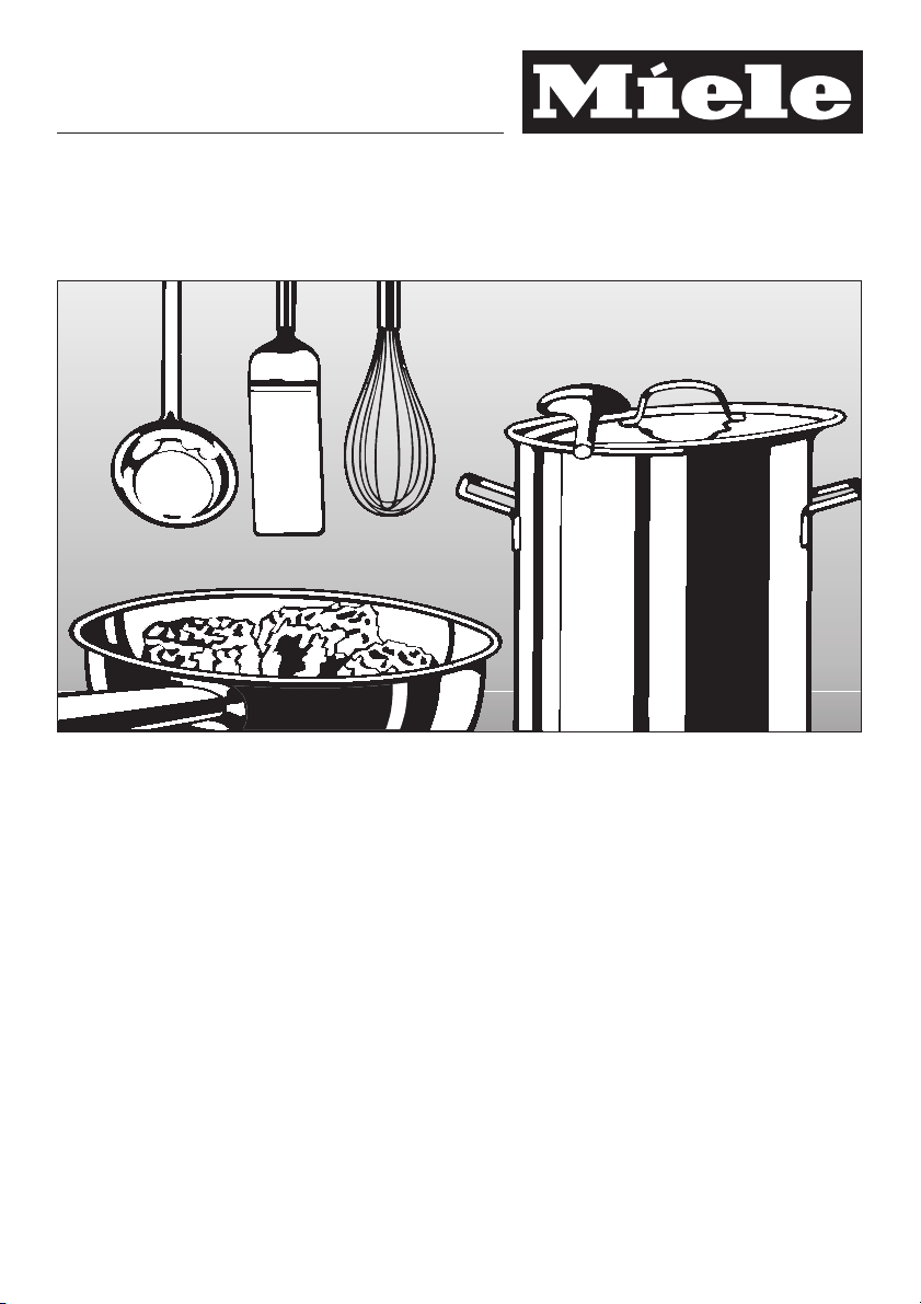
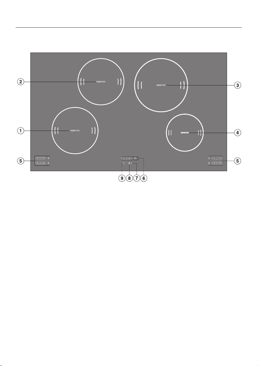
Guide to the appliance
KM 5731
abcd Cooking zones
e Cooking zone controls and displays (see “Cooking zone controls and displays”)
f Timer control and display (see “Timer control and display”)
g Safety lock indicator lamp
h Safety lock sensor switch
i Hob ON/OFF sensor switch
4
Page 5
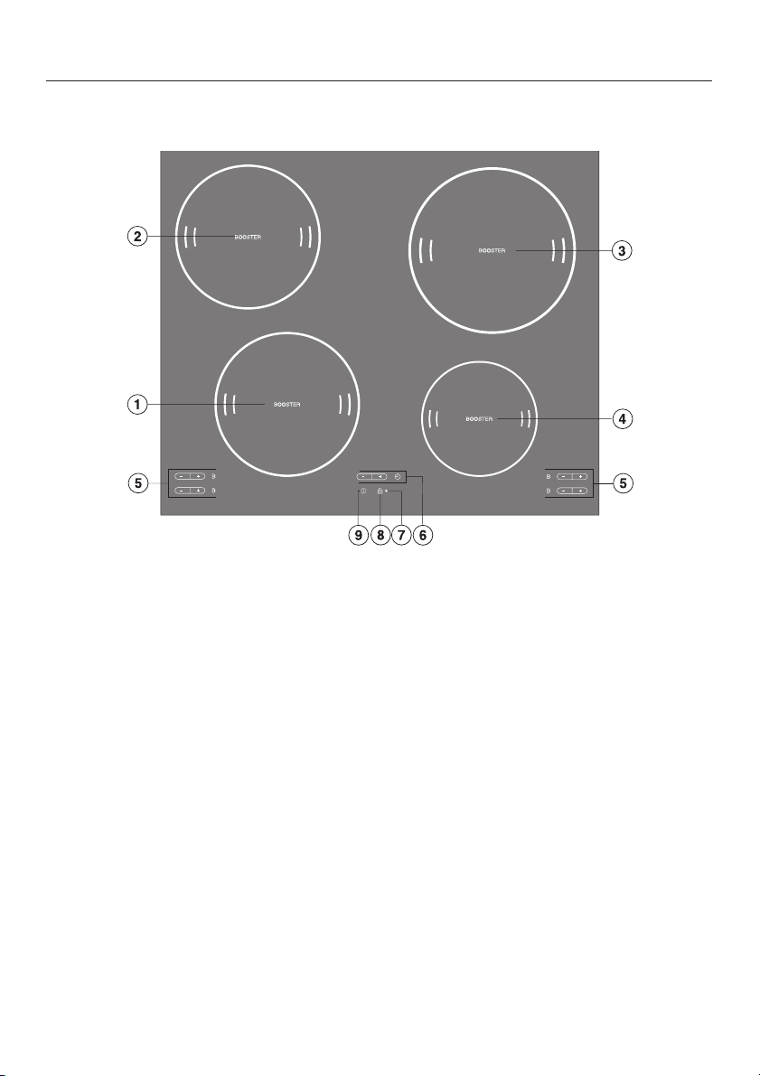
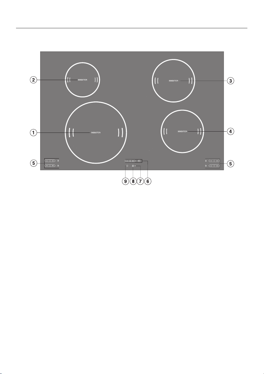
KM 5732 / KM 5736 / KM 5737
abcd Cooking zones
Guide to the appliance
e Cooking zone controls and displays (see “Cooking zone controls and displays”)
f Timer control and display (see “Timer control and display”)
g Safety lock indicator lamp
h Safety lock sensor switch
i Hob ON/OFF sensor switch
5
Page 6
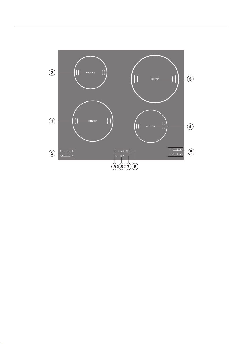
Guide to the appliance
KM 5733
abc Cooking zones
e Cooking zone controls and displays (see “Cooking zone controls and displays”)
f Timer control and display (see “Timer control and display”)
g Safety lock indicator lamp
h Safety lock sensor switch
i Hob ON/OFF sensor switch
6
Page 7
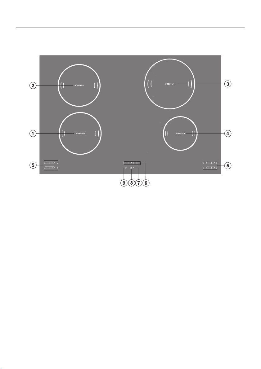
KM 5752 / KM 5757
abcd Cooking zones
Guide to the appliance
e Cooking zone controls and displays (see “Cooking zone controls and displays”)
f Timer control and display (see “Timer control and display”)
g Safety lock indicator lamp
h Safety lock sensor switch
i Hob ON/OFF sensor switch
7
Page 8
Guide to the appliance
KM 5753
abcd Cooking zones
e Cooking zone controls and displays (see “Cooking zone controls and displays”)
f Timer control and display (see “Timer control and display”)
g Safety lock indicator lamp
h Safety lock sensor switch
i Hob ON/OFF sensor switch
8
Page 9
KM 5755
abcd Cooking zones
Guide to the appliance
e Cooking zone controls and displays (see “Cooking zone controls and displays”)
f Timer control and display (see “Timer control and display”)
g Safety lock indicator lamp
h Safety lock sensor switch
i Hob ON/OFF sensor switch
9
Page 10
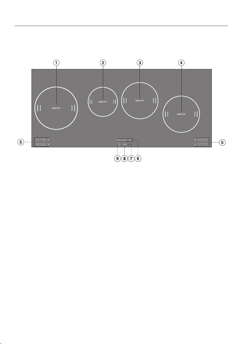
Guide to the appliance
KM 5775
abcd Cooking zones
e Cooking zone controls and displays (see “Cooking zone controls and displays”)
f Timer control and display (see “Timer control and display”)
g Safety lock indicator lamp
h Safety lock sensor switch
i Hob ON/OFF sensor switch
10
Page 11
Guide to the appliance
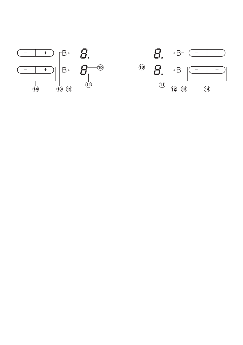
Cooking zone sensors and displays
j Displays:
0 = Cooking zone ready for use
1 to 9 = Power settings (for switched on hob)
# = Residual heat
ß = No pan on cooking zone or pan unsuitable
(see "Induction")
F = Fault (see "Safety switch-off")
A = Auto heat-up when the power setting range has been extended
P0 etc. = Programme (see "Programming")
S0 etc. = Status (see "Programming")
k Indicator lamp for Auto heat-up or extended power setting (see "Programming"),
e.g. the front left cooking zone
l Indicator lamp for booster
m Sensor switch for booster
n Power setting sensor switches
11
Page 12
Guide to the appliance
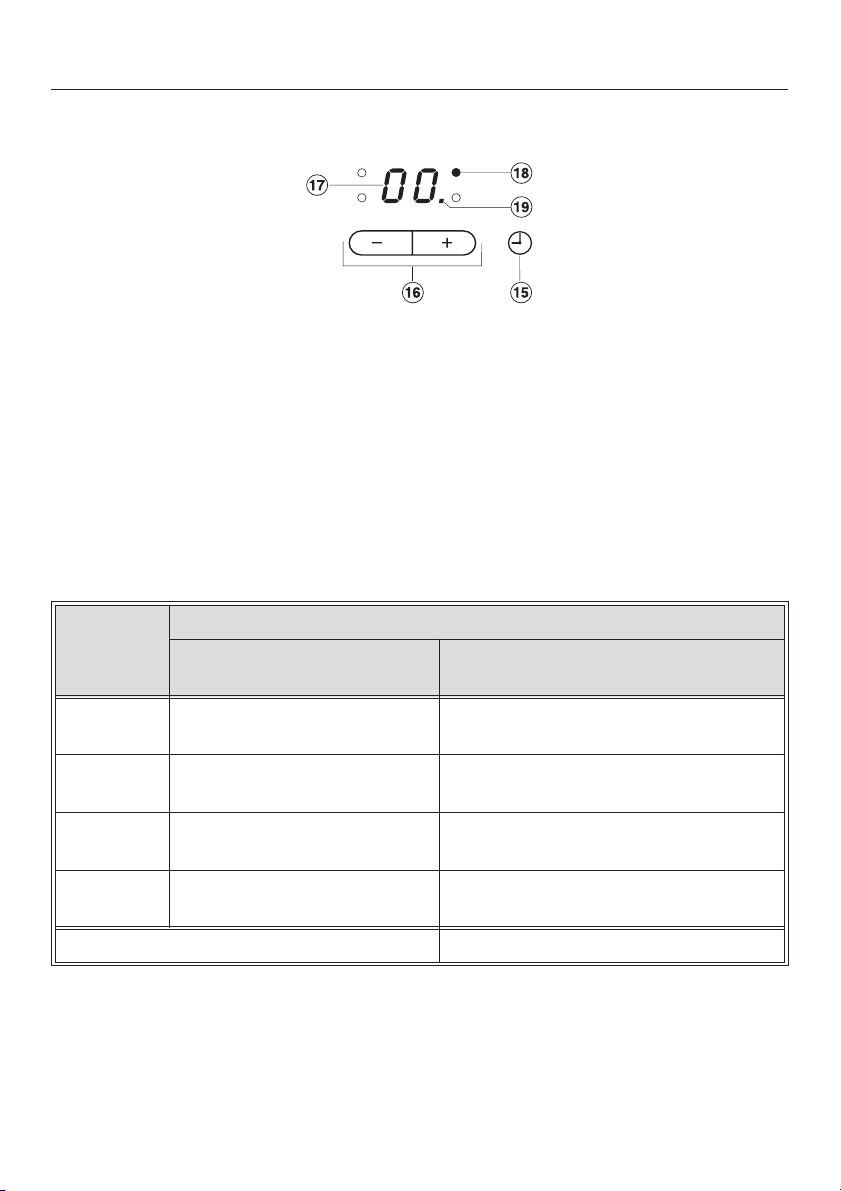
Timer control and display
o Sensor switch for activating the timer, switching between functions and
selecting automatic switch-off for a cooking zone.
p Sensor switch for setting the time
q Time display
r Indicator lamp for automatic switch-off, e.g. of the rear right cooking zone
s Indicator lamp for minute minder
Cooking zones
Cooking
zone
minimum to maximum
y
w
x
z
* Pans of any base diameter within the given range may be used.
** The wattage quoted may vary depending on the size and material of the pans
used.
12
KM 5731 / KM 5752 / KM 5755 / KM 5757
Rating in watts for 230 V**
Ø in cm*
14 - 20 normal:
with booster:
14 - 20 normal:
with booster:
16 - 23 normal:
with booster:
10 - 16 normal:
with booster:
Total: 7400
1850
2500
1850
2500
2300
3200
1400
1800
Page 13
Guide to the appliance
Cooking
zone
y
w
x
z
Cooking zone KM 5733
f 18 - 28 normal:
x
z
minimum to maximum
Ø in cm*
14 - 20 normal:
10 - 16 normal:
16 - 23 normal:
10 - 16 normal:
minimum to maximum
Ø in cm*
14 - 20 normal:
10 - 16 normal:
KM 5732 / KM 5736
Rating in watts for 230 V**
with booster:
with booster:
with booster:
with booster:
Total: 7400
Rating in watts for 230 V**
with booster:
with booster:
with booster:
Total: 6900
1850
2500
1400
1800
2300
3200
1400
1800
2400
3200
1850
2500
1400
1800
* Pans of any base diameter within the given range may be used.
** The wattage quoted may vary depending on the size and material of the pans
used.
13
Page 14
Guide to the appliance
Cooking
zone
y
w
x
z
Cooking zone KM 5753
y
w
x
z
minimum to maximum
Ø in cm*
14 - 20 normal:
10 - 16 normal:
16 - 23 normal:
10 - 16 normal:
minimum to maximum
Ø in cm*
18 - 28 normal:
10 - 16 normal:
14 - 20 normal:
14 - 20 normal:
KM 5737
Rating in watts for 230 V**
with booster:
with booster:
with booster:
with booster:
Total: 7400
Rating in watts for 230 V**
with booster:
with booster:
with booster:
with booster:
Total: 7400
1850
2500
1400
1800
2300
3200
1400
1800
2400
3200
1400
1800
1850
2500
1850
2500
* Pans of any base diameter within the given range may be used.
** The wattage quoted may vary depending on the size and material of the pans
used.
14
Page 15
Guide to the appliance
Cooking zone KM 5775
minimum to maximum
Ø in cm*
y
w
x
z
* Pans of any base diameter within the given range may be used.
** The wattage quoted may vary depending on the size and material of the pans
used.
16 - 23 normal:
10 - 16 normal:
14 - 20 normal:
14 - 20 normal:
Rating in watts for 230 V**
2300
with booster:
with booster:
with booster:
with booster:
Total: 7400
3200
1400
1800
1850
2500
1850
2500
15
Page 16
Warning and Safety instructions
Technical safety
To avoid the risk of accidents and
damage to the appliance, please
read these instructions carefully
before using it for the first time. They
contain important notes on its
installation, safety, use and
maintenance.
The appliance must be installed and
~
connected by a suitably qualified and
competent person in strict accordance
with current local and national safety
regulations. The manufacturer cannot
be held liable for damage caused by
incorrect installation or connection.
The use of the appliance by the
elderly or infirm or those who have
not used the appliance before
should be supervised by a
competent and responsible person
to avoid the risk of injury.
A data plate for your appliance is
supplied with this documentation. It
should be stuck into the space
provided at the end of the instruction
book.
Keep these instructions in a safe
place for reference, and pass them
on to any future user.
The electrical safety of this
~
appliance can only be guaranteed
when continuity is complete between it
and an effective earthing system which
complies with current local and national
safety regulations. It is most important
that this basic safety requirement is
present and regularly tested, and
where there is any doubt, the
household wiring system should be
inspected by a qualified electrician.
The manufacturer cannot be held liable
for the consequences of an inadequate
earthing system (e.g. electric shock).
Do not connect the appliance to the
~
mains electricity supply by an extension
lead. Extension leads do not guarantee
the required safety of the appliance
(e.g. danger of overheating).
16
Page 17

Warning and Safety instructions
Never open the casing of the
~
appliance.
Tampering with electrical connections
or components is highly dangerous to
the user and can cause operational
faults.
On hobs with bevelled glass edges
~
a small gap may be visible between the
hob and the worktop during the first few
days after installation. This gap will
reduce with time as the appliance is
used and will not affect the electrical
safety of your appliance.
Correct usage
For safety reasons this appliance
~
must only be operated after it has been
built in. This is necessary to ensure that
all electrical components are shielded.
This appliance is intended for
~
domestic use only and is not to be used
for commercial purposes.
If the hob is built in over a pyrolitic
~
oven, the hob should not be used whilst
the pyrolitic process is being carried
out, as this could trigger the
overheating protection mechanism on
the hob (see relevant section).
Use this appliance for the
~
preparation of food only. Any other
usage is at the owner's risk and could
be dangerous. The manufacturer
cannot be held liable for damage
resulting from incorrect or improper use
or operation.
17
Page 18

Warning and Safety instructions
Safety with children
Use the safety lock to prevent
~
children operating the appliance or
altering the settings.
The appliance is only intended for
~
use by adults who have read these
instructions.
This appliance is not a toy! To avoid
~
the risk of injury, keep children well
away, and do not allow them to play
with it or use the controls. They will not
understand the potential dangers
posed by it. They should be supervised
whenever you are working in the
kitchen.
Older children may use the
~
appliance only when its operation has
been clearly explained to them and
they are able to use it safely,
recognising the dangers of misuse.
The appliance gets hot when in use
~
and remains hot for quite a while after
being switched off. To safeguard
against burning, keep children well
away from the appliance at all times.
Keep all pans out of reach of
~
children. Turn pan handles inwards
away from the edge of the hob. Danger
of burning or scalding. Special hob
guards are available from good retail
outlets.
Packaging, e.g. cling film,
~
polystyrene and plastic wrappings,
must be kept out of the reach of babies
and young children. Danger of
suffocation. Dispose of or recycle all
packaging safely as soon as possible.
Do not store anything which might
~
arouse a child's interest in storage
areas above or next to the appliance.
Otherwise they could be tempted into
climbing onto the appliance with the
risk of burning themselves.
18
Page 19

Warning and Safety instructions
Protecting the appliance from
damage
Do not drop anything on the ceramic
~
surface. Even a light object could
cause damage in certain
circumstances.
Do not use pots or pans on the
~
ceramic hob with bases with
pronounced edges or or ridges, e.g.
cast iron pans. These could scratch or
scour the hob surface permanently.
Grains of salt and sand can also
scratch.
Do not allow either solid or liquid
~
sugar, or pieces of plastic or aluminium
foil to get onto the cooking zones when
they are hot. If this should occur,
switch off the appliance, and carefully,
scrape off all the sugar, plastic or
aluminium residues from the hob whilst
they are still hot, using a shielded
scaper blade. Take care not to burn
yourself.
If residues are allowed to cool before
being removed, the ceramic surface
will be susceptible to pitting or even
cracking.
Clean the appliance once it has cooled
down.
Never place hot pans near the
~
control area. This could damage the
electronic unit underneath.
This hob is fitted with a cooling fan.
~
If a drawer is fitted directly underneath
the hob, ensure that there is sufficient
space between the drawer and its
contents and the underside of the
appliance in order to ensure sufficient
ventilation for the hob. Do not store
small items or paper in the drawer.
They could get in through the
ventilation slots or be sucked into the
housing by the fan and damage the fan
or impair cooling.
In countries where there are areas
~
which may be subject to infestation by
cockroaches or other vermin, pay
particular attention to keeping the
appliance and its surroundings in a
clean condition at all times. Any
damage caused by cockroaches or
other vermin will not be covered by the
guarantee.
Do not use a steam cleaner to clean
~
this appliance. The steam could attack
the electrical components and cause a
short circuit. Pressurised steam could
cause permanent damage to the
surface and to other components, for
which the manufacturer cannot accept
liability.
19
Page 20

Warning and Safety instructions
Protection from burning and
scalding
The appliance gets hot when in use
~
and remains hot for quite a while after
being switched off. There is a danger
of burning until the residual heat
indicators go out.
For added protection, it is advisable
~
to use heat-resistant pot holders or
gloves when using the appliance. Do
not let them get damp or wet, as this
causes heat to transfer through the
material more quickly with the risk of
scalding or burning yourself.
Do not heat up unopened tins of
~
food on the hob, as pressure will build
up in the tin and it can explode. This
could result in injury and scalding or
damage.
Do not use the appliance as a
~
resting place for anything else. Take
particular care never to place cutlery or
other metal objects on the hob. When
the appliance is switched on either
deliberately or by mistake, or when
there is residual heat present, there is
the risk of metal objects heating up,
with a danger of burning.
Depending on the material, other
objects left on the hob could also melt
or catch fire.
Damp pan lids might adhere to the
ceramic surface and be difficult to
dislodge.
Switch the cooking zones off after use.
Do not cover the appliance, e.g.
~
with a cloth, kitchen foil, etc. This could
be a fire hazard if the appliance is
switched on by mistake.
Never leave the appliance
~
unattended when cooking with oil or fat
as these are fire hazards if overheated.
Very hot oil can catch fire and could
even set a cooker hood above on fire.
Always heat fat slowly, watching as it
heats.
If, despite this, oil or fat does catch
~
fire, do not attempt to put out the flames
with water. Use a suitable fire blanket,
saucepan lid, damp towel or similar to
smother the flames.
Do not flambé under a cooker hood.
~
The flames could set the cooker hood
on fire.
20
Page 21

Warning and Safety instructions
Appliance faults
In the event of damage or a defect,
~
switch off the appliance immediately.
Disconnect completely from the
electricity supply. If the appliance has
not yet been fully installed, the
electricity cable must be disconnected
from the supply point. If connected via
a plug and socket, switch off at the
socket and withdraw the plug. Contact
the Miele Service Department.
Do not reconnect the appliance to the
mains electricity supply until after it has
been repaired.
If there is any damage to the
~
ceramic surface, the appliance must be
disconnected from the mains electricity
supply immediately, and not used until
it has been repaired. Danger of electric
shock.
Repairs may only be carried out by
~
a suitably qualified and competent
person. Repairs and other work by
unqualified persons could be very
dangerous and could damage the
appliance. The manufacturer cannot be
held liable for unauthorised work. Never
open the housing of the appliance.
While the appliance is under
~
guarantee, repairs should only be
undertaken by a service engineer
authorised by the manufacturer.
Otherwise the guarantee is invalidated.
21
Page 22

Warning and Safety instructions
Futher safety notes
For people fitted with a heart
~
pacemaker:
Please note that the area immediately
surrounding the hob is
electromagnetically charged, and that
this could affect a pacemaker.
If in any doubt, consult the
manufacturer of the pacemaker or your
doctor.
Ensure pans are placed centrally
~
over the cooking zone to prevent
unnecessary exposure to the
electromagnetic field.
When using an electric socket near
~
the appliance, care should be taken
that the cable of the electrical
appliance does not come into contact
with the hot appliance. The insulation
on the cable could become damaged,
giving rise to an electric shock hazard.
Always ensure that food is
~
sufficiently cooked or reheated. Many
factors will affect the overall cooking
time, including the size and amount of
food and its temperature. Some foods
may contain micro-organisms which are
only destroyed by thorough cooking at
a sufficiently high temperature for long
enough. Therefore when cooking or
reheating food such as poultry, it is
particularly important the food is
completely cooked through. If in doubt,
select a longer cooking or reheating
time.
Do not use plastic or aluminium foil
~
containers. These melt at high
temperatures and could damage the
ceramic surface. Fire hazard.
To prevent damage to items which
~
are susceptible to magnetic fields, e.g.
credit cards, diskettes, pocket
calculators etc, do not leave them in the
immediate vicinity of the hob.
Spray canisters, aerosols and other
~
inflammable substances must not be
stored in a drawer under the hob.
Cutlery inserts must be heat-resistant.
22
Page 23

Caring for the environment
Disposal of the packing
material
The transport and protective packing
has been selected from materials which
are environmentally friendly for
disposal, and can normally be
recycled.
Ensure that any plastic wrappings,
bags, etc. are disposed of safely and
kept out of the reach of babies and
young children. Danger of suffocation!
Rather than just throwing these
materials away, please ensure they are
offered for recycling.
Disposal of your old appliance
Electrical and electronic appliances
often contain materials which, if
handled or disposed of incorrectly,
could be potentially hazardous to
human health and to the environment.
They are, however, essential for the
correct functioning of your appliance.
Please do not therefore dispose of it
with your household waste.
Please dispose of it at your local
community waste collection/recycling
centre, and ensure that it presents no
danger to children while being stored
for disposal.
It should be disconnected from the
mains electricity supply by a competent
person.
23
Page 24

Before using for the first time
Please stick the extra data plate for the
appliance supplied with this
documentation in the space provided in
the "After sales service" section of this
booklet.
Cleaning for the first time
Remove any protective wrapping and
stickers.
Before using for the first time, clean the
appliance with a damp cloth only and
then wipe dry.
Do not use washing up liquid to
clean the ceramic surface as it can
leave a blue sheen which may be
difficult to remove.
Heating up for the first time
On hobs with bevelled glass edges,
a small gap may be visible between
the hob and the worktop during the
first few days after installation. This
gap will reduce with time as the
appliance is used and will not affect
the electrical safety of your
appliance.
Metal components have a protective
coating which may give off a slight
smell when heated up for the first time.
The smell and any fumes given off do
not mean that the appliance is
defective or has been wrongly installed,
and they are not harmful to health.
24
Page 25

Induction
How it works
An induction coil is located under each
cooking zone. When a cooking zone is
switched on, this coil creates a
magnetic field which impacts directly
on the base of the pan and heats it up.
The cooking zone itself is heated up
indirectly by the heat given off by the
pan.
Induction cooking zones only work
when a ferromagnetic pan is placed on
it (see "Pans").
Induction automatically recognises the
size of the pan, i.e. heat is only
generated in the area covered by the
base of the pan.
The cooking zone will not work:
– if it is switched on without a pan in
place, or if the pan is unsuitable
(non-magnetic base).
– if the diameter of the base of the pan
is too small.
If a suitable pan is placed on the
cooking zone within 3 minutes, the ß
will go out and you can continue as
normal.
If no pan or an unsuitable pan is placed
on the cooking zone, the cooking zone
and the hob will switch off automatically
after 3 minutes.
Take particular care never to place
cutlery or other metal objects on the
hob. When the appliance is
switched on, either deliberately or
by mistake, or when there is residual
heat present, there is the risk of
metal objects heating up, with a
danger of burning.
Depending on the material, other
objects left on the hob could also
melt or catch fire. Switch the zones
off after use.
–
if the pan is taken off the cooking
zone when it is switched on.
If this happens, ß will flash in the
relevant cooking zone display
alternating with 0 or the last power
setting selected .
25
Page 26

Induction
Noises
When using an induction cooking zone,
the following noises can occur in the
pan, depending on what it is made of
and how it has been constructed.
On the higher power settings, it
–
might buzz. This will decrease or
cease altogether when the power
setting is reduced.
If the pan base is made of layers of
–
different materials (e.g. in a
sandwiched base), it might emit a
cracking sound.
– Whistling might occur if linked zones
(see "Booster function") are being
used on the highest setting at the
same time, and the pans also have
bases made of layers of different
materials.
– You might hear a clicking sound from
the electronic switches, especially on
lower settings.
The appliance has a cooling fan to help
extend the life of the electronics. When
the hob is being used intensively, this
will come on and you will hear a
whirring sound. The fan may continue
to run after the appliance has been
switched off.
26
Page 27

Induction
Pans
Suitable pans include:
stainless steel pans with a magnetic
–
base
enamelled steel pans
–
cast iron pans
–
Unsuitable pans:
stainless steel pans without a
–
magnetic base
aluminium and copper pans
–
glass, ceramic or earthenware pots
–
and pans
To test whether a pot or pan is suitable
for use on an induction hob, hold a
magnet to the base of the pan. If the
magnet sticks, the pan is suitable.
Please be aware that the properties of
the pan base can affect the eveness
with which food heats up in the pan.
Pan size
To make optimum use of the cooking
zones, choose pans with diameters
larger than the innermost markings but
smaller than the outermost markings. If
the diameter of the pan is smaller than
the innermost marking, the induction
heating will not work. The zone will
behave as if it had no pan on it.
Please note that the maximum diameter
quoted by manufacturers often refers to
the diameter of the top rim of the pot or
pan. The diameter of the base
(generally smaller) is more important.
Tips on saving energy
Use a pan lid whenever possible to
minimise heat loss.
Unless the pan manufacturer states
that you can do so, do not use pans
with very thin bases on this hob, and
never heat up empty pans as they
could get damaged. This could also
damage the appliance.
uncovered covered
27
Page 28

Operation
Sensors
This hob is equipped with electronic
sensors which react to finger contact.
To operate a cooking zone, touch the
relevant sensor. Each time you touch a
sensor, an audible tone sounds.
Take care only to touch the middle
of the sensor required. Keep the
control panel clean, and do not
place anything on top of it. The
sensors may fail to react or they
could mistake the article or any dirt
for a fingertip contact, thereby
activating a function or even causing
the hob to switch off automatically
(see Safety switch-off.)
Never place hot pans on the sensor
switches. The electronic unit
underneath could get damaged.
Switching on
The hob must be switched on before
any of the zones can be used.
Do not leave the appliance
unattended whilst it is being used.
To switch the hob on:
Touch the ON/OFF sensor s.
^
0 appears in each of the cooking zone
displays. If no further entry is made, the
hob will switch itself off after a few
seconds for safety reasons.
To switch a cooking zone on:
^ Select a power setting between 1 and
9 by touching the - or + sensor.
To select cooking with Auto heat-up,
press the - sensor first (see "Auto
heat-up"). To select cooking without
Auto heat-up, press the + sensor first.
If you wish to switch on another
cooking zone, and the 0 for that zone
has already gone out, simply press the
- or + briefly. The 0 will reappear and
you can select a power setting (with or
without Auto heat-up).
28
Page 29

Operation
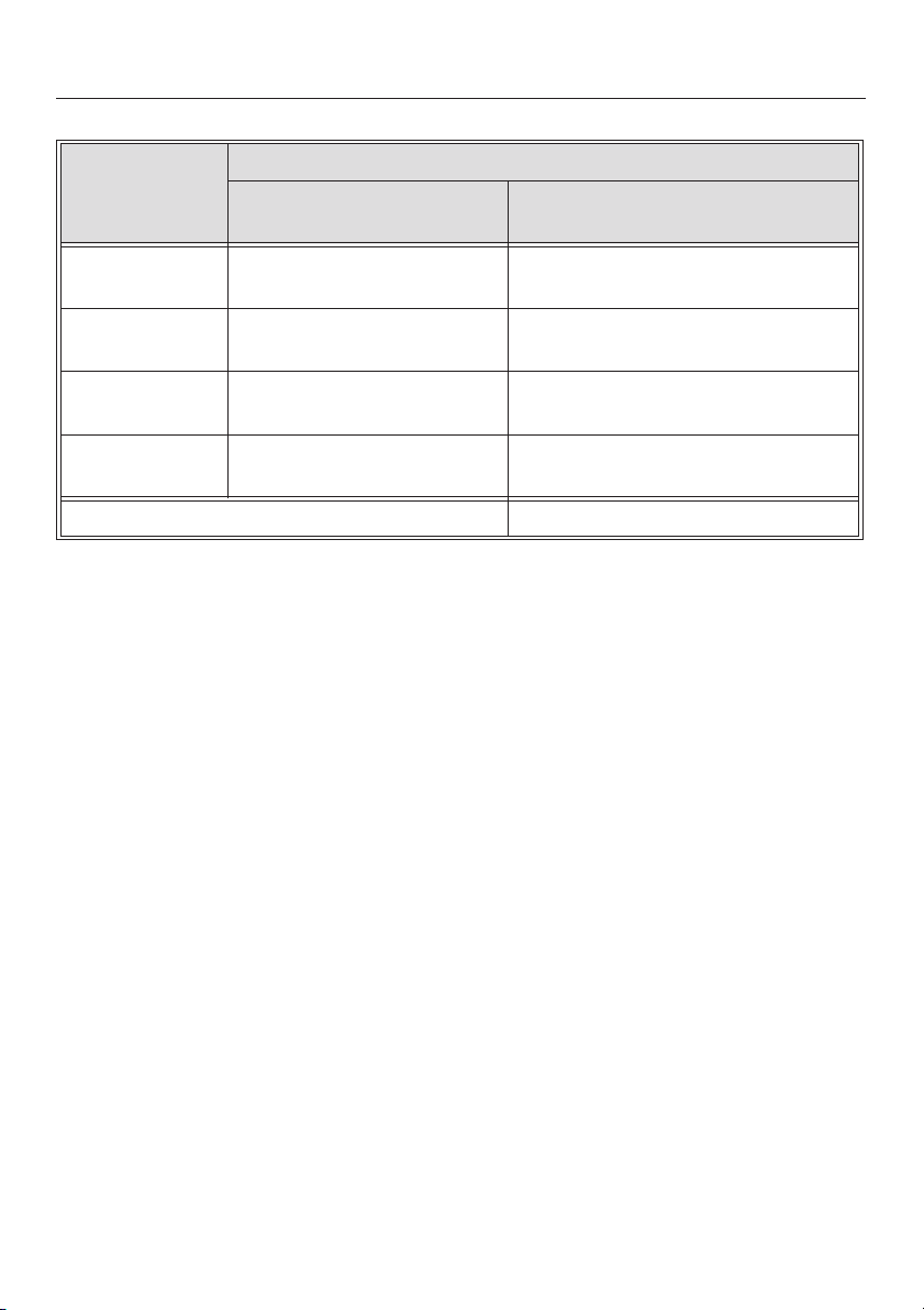
Settings
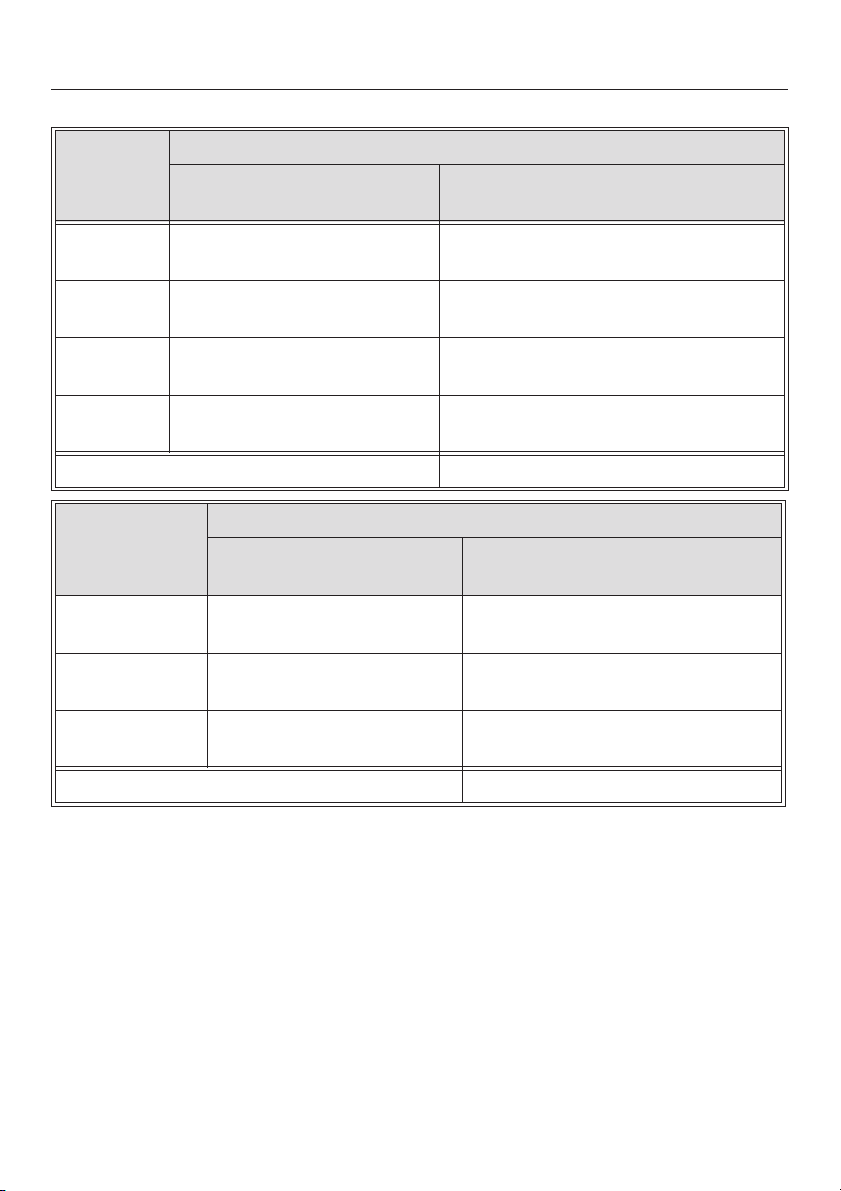
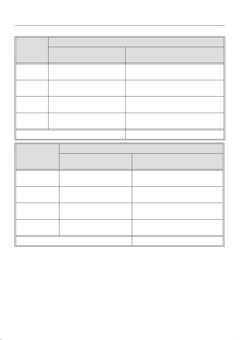
Cooking process Settings*
standard
factory settings
(9 settings)
Melting butter
Dissolving gelatine
Warming small quantities of food/liquid
Keeping warm food which sticks easily
Cooking rice
Defrosting frozen vegetables
Warming liquid and semi-solid foods
Thickening sauces, e.g. Hollandaise
Making porridge
Preparing omelettes, lightly fried eggs
Steaming fruit
Defrosting deep frozen food
Steaming vegetables, fish
Cooking broths, pulse soups
Bringing large quantities of food to the boil
Cooking dumplings
Gentle braising (without overheating the fat) of meat, fish,
vegetables, fried eggs
Frying pancakes etc. 8 8 - 8.
Boiling large quantities of water
Bringing to the boil
1-2 1-2.
3 3-3.
4 4-4.
55
6 5.-6
7 6.-7.
99
extended
settings**
(17 settings)
* These settings, which envisage approx. 4 helpings, should only be taken as a guide. With deep
pans, larger quantities or when cooking without a lid, a higher setting is required. For smaller
quantities, select a lower setting.
** If you wish to fine-tune a setting, you can extend the power setting range (see "Programming").
The intermediate setting will be represented by an illuminated dot next to the number.
29
Page 30

Operation
Auto heat-up
When Auto heat-up has been activated,
the cooking zone switches on
automatically at the highest setting and
then switches to the continued cooking
setting which you have previously
selected. The heat-up time depends on
which continued cooking setting has
been chosen (see chart).
Taking a pan off the zone whilst Auto
heat-up is in operation interrupts the
Auto heat-up. It will resume if a pan is
placed back on the zone within 3
minutes.
Continued
cooking setting*
1 0:15
1. 0:15
2 0:15
2. 0:15
3 0:25
3. 0:25
4 0:50
4. 0:50
5 2:00
5. 5:50
6 5:50
6. 2:50
7 2:50
Heat-up time
in minutes and
seconds
(approx.)
30
7. 2:50
8 2:50
8. 2:50
9-
* The continued cooking settings with
a dot after the number are only
available if the power level range has
been extended (see "Programming").
Page 31

Operation
How to activate Auto heat-up
Press the - sensor until the required
^
continued cooking setting appears,
e.g. 6.
During the heat-up time a dot will light
up to the right of the continued cooking
setting, and go out at the end of it.
At any point during the Auto heat-up
time you can use - or + to lower or
increase the continued cooking setting.
The Auto heat-up time will alter
accordingly.
In the extended range of settings (see
"Programming - P6."), A flashes
alternately with the continued cooking
setting until the heat-up time has
finished.
31
Page 32

Operation
Booster function
All of the cooking zones are equipped
with a booster function, i. e. an increase
in the power level.
If activated, the zones will operate on
power setting 9 with an extra boost of
power for a period of 10 minutes. This
boost is intended for quickly bringing
large quantities of water to the boil, e.g.
when cooking pasta.
A maximum of two booster functions
can be used at any one time.
Taking a pan off the zone whilst the
booster is in operation interrupts the
booster function. It will resume if a pan
is placed back on the zone within 3
minutes.
The extra boost of energy is only
available by taking a proportion of
energy away from another cooking
zone. For this reason, the cooking
zones are networked in pairs as shown.
When the booster is switched on, the
following happens:
if Auto heat-up is activated on either
–
zone in the same network, this will be
switched off.
the power level on the other linked
–
cooking zone will sometimes
decrease.
Proceed as follows:
Touch the B sensor for the relevant
^
cooking zone.
Power setting 9 will show in the cooking
zone display, and the indicator lamp for
the booster will also light up.
After 10 minutes, the zone will
automatically revert to power setting 9.
To switch off the booster before this,
touch either the B sensor or the sensor for the appropriate cooking
zone.
32
If a power setting is selected before the
booster function is switched on, the
zone will revert to this pre-selected
power setting when the booster is
switched off, or automatically at the end
of the booster time.
Page 33

Operation
Switching off and residual heat
indicators
To switch off a cooking zone:
Touch the - and + sensors for the
^
zone you want to switch off at the
same time.
A 0 will light up in the display for that
zone for a few seconds. If the cooking
zone is still hot, residual heat will then
be indicated in the display.
To switch off the hob:
^ Touch the ON/OFF sensor s.
This switches off all cooking zones. The
residual heat indicator will appear in the
display of any cooking zone which is
still hot.
The lines of the residual heat indicator
go out one after another as the cooking
zones cool down. The last horizontal
line only goes out when the cooking
zone is safe to touch.
The residual heat indicators also
react to hot dishes and plates being
placed on a cooking zone that is not
switched on.
Do not touch any zone or place any
heat sensitive items on a zone where
the residual heat indicator is lit up.
Danger of burning, and fire hazard.
Please note that the residual heat
indicators do not light up when there
is a fault message, even if the
cooking zones are hot.
33
Page 34

Safety features
Safety lock
Keep children away from the hob for
their own safety.
Your appliance is equipped with a
safety lock to prevent the hob and the
cooking zones being switched on or
any settings being altered.
The safety lock can be activated when
the hob is switched off as well as when
it is in use.
If the safety lock is activated when the
hob is switched off, then the hob
cannot be switched on.
If the safety lock is activated when the
hob is in use:
– The power levels for the cooking
zones and the timer settings cannot
be altered.
– The cooking zones and hob can be
switched off but once switched off
cannot be switched on again.
To activate the safety lock:
Touch the safety lock sensor $ until
^
the relevant indicator lamp comes on.
The indicator lamp will go out after a
short while.
The lamp will come on again to show
that the safety lock has been activated,
if
you touch the safety lock $ sensor.
–
you try to change a setting.
–
To deactivate the safety lock:
^ Touch the safety lock sensor $ until
the indicator lamp goes out.
You can alter the setting from one
finger to three finger operation (see
"Programming - P4") to make it harder
for children to operate the appliance.
Please note that the safety lock will
deactivate if there is a power cut.
34
Page 35

Safety features
Stop and Go
Your appliance has a Stop and Go
feature which, when activated, reduces
the power of all switched on cooking
zones to setting 1. When Stop and Go is
deactivated, the cooking zones resume
at the power level which was last set.
If Stop and Go is not deactivated, the
hob switches off after 1 hour.
If you wish to use this feature, you will
need to alter the factory setting (see
"Programming - P5").
To activate Stop and Go:
^ Touch the $ sensor until you hear
two consecutive beeps.
Be careful not to continue touching
the $ sensor for too long, as this will
activate the safety lock.
The indicator lamp for the safety lock
will start to flash. The power of the
cooking zones in use will be reduced to
setting 1, and a 1 will appear in the
corresponding cooking zone displays.
To deactivate Stop and Go:
Touch the $ sensor until the indicator
^
lamp goes out.
The cooking zones will now run at the
level that was previously set.
If automatic switch-off is programmed
for a cooking zone, activating Stop and
Go will interrupt the count down to the
switch-off time. When Stop and Go is
deactivated, the automatic switch-off
programme time will continue to run
without further interruption.
If a minute minder time has been set,
this will continue running and will not be
affected by Stop and Go.
35
Page 36

Safety features
Safety switch-off
Safety switch-off with an over-long
cooking time
Your hob is fitted with a safety
switch-off feature in case you forget to
switch it off yourself.
If one of the cooking zones is heated
for an unusually long period of time
(see chart), and the power settings are
not altered, the hob will switch itself off
automatically and the appropriate
residual heat indicator will appear.
Power setting* Maximum
operating time in
hours
1/1. 10
2/2. 5
3/3. 5
4/4. 4
5/5. 3
6/6. 2
Safety switch-off if the sensors are
covered
Your hob will switch off automatically if
one or several of the sensors remain
covered for longer than 10 seconds, for
example, by finger contact, food boiling
over or by an object such as an oven
glove or tea towel.
An audible tone will sound every 30
seconds (for a maximum of ten
minutes) and an F will flash in the
display for the sensor which is covered.
^ Clean the control area or remove the
obstruction.
This will turn off the tone and the F will
go out.
^ Switch the hob back on again with
the ON/OFF sensor s. The cooking
zones can now be used again as
normal.
7/7. 2
8/8. 2
91
* The power settings with a dot after
the number are only available if the
power setting range has been
extended (see "Programming - P6.").
^
To use the cooking zones again,
switch the hob back on in the usual
way.
36
Page 37

Safety features
Overheating protection
All of the induction coils and the cooling
element for the electronics are fitted
with an overheating protection
mechanism. To prevent the induction
coils and cooling element from
overheating, the overheating protection
mechanism works on the affected
cooking zone or on the entire hob in the
following ways:
If the booster function is being used,
–
this will be switched off.
The power level will be reduced.
–
– If an induction coil is affected, the
hob will switch off. The FE99 fault
message will be displayed.
The cooking zone can be used again
as soon as it has cooled down to a safe
level.
– If the cooling element is affected, the
power supply to the cooking zones
will be reduced, and the set power
level will continue to be displayed.
Overheating can be caused by:
heating up an empty pan
–
fats or oils being heated up on the
–
highest power setting.
there being insufficient ventilation to
–
the under side of the appliance.
If the overheating protection
mechanism triggers again, contact the
Service department.
As soon as the cooling element has
cooled down sufficiently, the cooking
zones will automatically continue to
operate at the original power setting.
37
Page 38

Timer
The hob is fitted with a timer which can
be used both as a minute minder and
to switch off the cooking zones
automatically.
These functions are explained below.
The Combi mode is described in the
section of that name.
You can set a time of 1 to 99 minutes.
Use the - sensor to reduce the time
from 99 to 00 and the + sensor to
increase the time from 00 to 99. The
display can be put back to 00 by
touching - and + at the same time.
When the set time has elapsed, 00 will
appear in the timer display for a few
seconds. At the same time an audible
tone will sound for a few seconds. To
turn the audible tone off before this,
touch the m sensor.
Setting the minute minder
The minute minder can be used with
the hob switched on or off. It works like
a manual kitchen timer.
Proceed as follows:
Touch the m, - or + sensor.
^
00 appears in the timer display, and the
minute minder indicator lamp will flash.
Whilst the indicator light is flashing,
^
touch the - or + sensor until the time
you require appears in the display,
e.g. 15 minutes.
The time then counts down in minutes.
The time remaining can be seen in the
display and changed at any time by
touching - or +.
38
Page 39

Switching a cooking zone off
automatically
It is only possible to programme a
cooking zone to switch off automatically
if a power setting has already been
selected for that zone. All of the
cooking zones can be programmed at
the same time.
Proceed as follows:
Select a power setting for the zone
^
you require, e.g. back right, in the
usual way.
^ Touch the m sensor.
Timer
Touch the - or + sensor until the time
^
you require appears in the display,
e.g. 15 minutes.
The time then counts down in minutes.
The time remaining can be seen in the
display and changed at any time by
touching - or +.
If you want to set another cooking zone
to switch off automatically, follow the
same steps as described above.
00 appears in the timer display, and the
minute minder indicator lamp will flash.
^ Touch the m sensor again.
The indicator lamp for the minute
minder in the timer display goes out,
and an indicator lamp for automatic
switch-off of a cooking zone flashes.
^
If several cooking zones are being
used, touch the m sensor repeatedly
until the indicator lamp flashes next
to the cooking zone you wish to use
this function for, e.g. back right.
The indicator lamps for the cooking
zones being used light up clockwise,
starting with the front left.
If more than one switch-off time is
programmed, the shortest time
remaining will show in the display, and
the indicator lamp for that particular
cooking zone will flash. All the other
indicator lamps will light up constantly.
If you want to check on the remaining
time for another zone, touch the m
sensor until the indicator lamp for the
zone you require flashes.
39
Page 40

Timer
Combi mode
The minute minder and automatic
switch-off functions can be used at the
same time.
If you have programmed in one or more
switch-off times, and would like to use
the minute minder as well:
Touch the m sensor repeatedly until
the minute minder indicator lamp
flashes.
If you are using the minute minder, and
would like to programme in one or more
switch-off times as well:
Touch the m sensor repeatedly until
the indicator lamp flashes for the
cooking zone required.
Shortly after the last entry, the shortest
remaining time will come up in the
display. If you want to check on another
remaining time, touch the m sensor
until the relevant indicator lamp flashes.
Starting with the shortest remaining
time which is showing in the display, all
cooking zones that are in use and the
minute minder are selected clockwise.
Timer factory settings
The timer is set at the factory so that it
starts with 01 or 99 when the + or sensor is touched.
This setting can be adjusted so that the
time you last used appears in the
display when you press + or - (see
"Programming - P4.").
Example:
If P4., S1 has been programmed, and
the last time the minute minder was
used was for 5 minutes, 00 will appear
in the display when you switch on the
Timer; when you then touch + or -, the
display will change to 05.
You can still select any time you want,
even if you have adjusted the timer
default setting.
40
Page 41

Cleaning and care
For Miele branded cleaning and
conditioning products see "Optional
accessories".
Do not use a steam cleaner to clean
this appliance. The steam could
reach electrical components and
cause a short circuit.
Only use proprietary cleaning
products which are suitable for
cleaning ceramic hobs. Never use
cleaners containing sand, soda,
alkalis, acids or chlorides, oven
sprays, dishwasher cleaner, nor
steel wool, abrasive cleaning
agents, hard brushes, scouring
pads and cloths. You should also
avoid using sponges etc. which
have previously been used with
abrasive cleaning agents, as this will
damage the surface.
Do not use washing up liquid to
clean the ceramic surface, as it can
leave a blue sheen which may be
difficult to remove.
The appliance should be cleaned after
each use. Allow the hob to cool down
before cleaning.
Wipe all coarse soiling off using a
damp cloth. Stubborn soiling may need
to be removed with a shielded scraper
blade.
Finally, clean the hob with a suitable
proprietary ceramic hob cleaner (see
"Optional accessories") applied with
kitchen paper or a clean cloth. Do not
apply cleaner whilst the hob is still hot,
as this could result in marking. Please
follow the manufacturer's instructions.
Finally wipe the appliance with a damp
cloth, and then dry it with a clean, soft
cloth. Ensure that all cleaner residues
are removed. Residues can burn onto
the hob the next time it is used, and
cause damage to the ceramic surface.
Do not use sharp objects which may
damage the seals between the
ceramic surface and the frame or
between the frame and the worktop.
To prevent the risk of spillages
burning on, remove any soiling as
soon as possible, and ensure that
pan bases are clean, dry and free of
grease.
41
Page 42

Cleaning and care
Spots caused by limescale deposits,
water and aluminium residues (which
have a metalic appearance) can be
removed using the ceramic cleaner.
Should any sugar, plastic or
aluminium foil spill or fall on to a hot
cooking zone while it is in use, first
switch off the appliance. Then carefully
scrape off all the sugar, plastic or
aluminium residues from the hob whilst
they are still hot using a shielded
scraper blade. Take care not to burn
yourself.
Allow the cooking zone to cool down,
and then clean as described above
with a suitable proprietary ceramic hob
cleaner.
42
Page 43

Programming
You can change the standard settings
of your hob (see chart).
Proceed as follows:
With the hob switched off, touch the
^
hob ON/OFF sensor s and the safety
lock sensor $ at the same time until
the indicator lamp for the safety lock
flashes.
A P (Programme) and an S (Status) will
appear in the cooking zone display with
a number which shows the current
setting (see chart).
^ To select the programme you want,
touch the + or - sensor for the front
left cooking zone, then select the
required status by touching the + or sensor for the front right cooking
zone (see chart). You can alter
several programmes one after the
other in this manner.
To store the new settings in memory,
touch the hob ON/OFF sensor s until
the displays go out.
If you do not wish to store the settings
in memory, touch the safety lock sensor
$ until the displays go out.
43
Page 44

Programming
Programme* Status** Setting
P0Demonstration mode and
factory default settings
P1Keypad tone when a
sensor is touched
P2Induction warning tone
when there is no pan or
the pan is unsuitable
P3Audible tone for the Timer S 0 Off
P4Safety lock S0 One finger locking using $
P5Stop and Go S0 Off
P0.Power setting when the
cooking zone is switched
on
S 0 Demonstration mode on
S1 Demonstration mode off
S 9 Factory default settings
reinstated
S 0 Off
S1 On
S0 Off
S1 On
S1 Audible tone on for 10 seconds
S 2 Audible tone on for 4 minutes
S 1 Three finger locking using $ and
+ on the two right-hand cooking
zones
S1 On
S0 0
S 1 5 (can only be selected when
Auto heat-up is activated)
* Programmes/Statuses not shown here have no allocation.
** The factory default settings are shown in bold.
44
Page 45

Programming
Programme* Status** Setting
P2.Auto heat-up S 0 Off
S1 Activated by selecting the
power setting using -
S 2 Activated by selecting the
power setting using +
S 3 Activated every time the
hob is switched on
P3.Residual heat indicator S 0 H as the residual heat
indicator symbol
S1 # as the residual heat
indicator symbol
P4.Timer factory settings S0 01 or 99
S 1 The most recently set time
(see "Timer default setting")
P5.Timer functions S 0 Minute minder only
S 1 Auto switch-off only
S2 Minute minder and Auto
switch-off
P6.Power setting range S0 9 power settings
(1 to 9)
S 1 17 power settings
(1, 1., 2, 2., 3 ... to 9)
If the Auto heat-up setting is
selected, an A will flash
alternately with the
continued cooking setting in
the display.
* Programmes not shown here have no allocation.
** The factory default settings are shown in bold.
45
Page 46

Problem solving guide
Installation work and repairs to
electrical appliances must only be
carried out by a suitably qualified
and competent person in strict
accordance with current local and
national safety regulations (BS 7671
in the UK). Repairs and other work
by unqualified persons could be
dangerous. The manufacturer
cannot be held liable for
unauthorised work.
What to do if, ...
... the hob or cooking zones cannot
be switched on
Check whether
... the hob can be switched on and
settings selected, but the cooking
zones do not heat up
Check whether you set the demo-mode
setting by mistake (see "Programming P0").
... an ß appears in the display for a
cooking zone
Check whether
the zone was switched on by mistake
–
without a pan on it.
– the pan being used is suitable for
use on an induction zone, and that it
is large enough (see "Suitable pans").
– the pans being used are suitable.
– the safety lock is activated.
If necessary, deactivate it (see
"Safety lock").
–
the mains fuse has blown.
If none of the above is the case, then
disconnect the appliance from the
electricity supply for approx. 1 minute.
To do this:
–
switch off at the mains, or
–
withdraw the mains fuse.
Reset the trip switch in the mains fuse
box, and switch the appliance back on.
If it still will not switch on, contact a
qualified electrician or the Miele Service
Department.
46
... an individual cooking zone or the
whole hob has switched itself off
automatically
The safety switch-off feature or the
overheating protection mechanism has
been triggered (see "Safety switch-off"
and "Overheating protection").
Page 47

Problem solving guide
... one of the following has occurred:
The booster has automatically
–
switched off early.
The power level has dropped.
–
The cooking zone is not working in
–
the usual way at the power level set.
The overheating protection mechanism
has been triggered (see "Overheating
protection").
... the food in the pan hardly heats up
or does not heat up at all when the
Auto heat-up function is switched on
This could be because:
– there is too much food in the pan.
– the pan is not conducting heat
properly.
Select a higher continued cooking
setting next time, or start cooking at the
highest setting and then turn down to a
lower setting manually later on.
... The cooling fan continues to run
after the appliance has been
switched off
This is not a fault. The fan will continue
running until the appliance has cooled
down. It will then switch itself off
automatically.
... an F appears in the display for the
rear cooking zones, an E appears in
the display for the front cooking
zones and numbers appear in the
timer display
FE99:
The overheating protection mechanism
for the induction coil has been
triggered. The cooking zone can be
used again as soon as it has cooled
down to a safe level.
With other fault messages:
Interrupt the power supply to the hob
for approx. 1 minute.
If the problem persists after
reconnecting the appliance to the
power supply, please contact the Miele
Service department.
47
Page 48

After sales service, data plate
In the event of any faults which you cannot remedy yourself, or if the appliance is
under guarantee, please contact:
Your Miele dealer, or
–
the Miele Customer Contact Centre (see back cover for address).
–
When contacting Miele, please quote the model and serial number of your
appliance. These are given on the data plate.
Please note that telephone calls may be monitored and recorded to improve
our service.
Space in which to stick the extra data plate supplied with the appliance. Ensure
that the model number is the same as the one on the front of these instructions.
48
Page 49

Installation
Safety instructions for
installation
Fit wall units and extractor hood
before fitting the hob to avoid
damaging the surface.
The veneer or laminate coatings of
~
worktops (or adjacent kitchen units)
must be treated with 100 °C
heat-resistant adhesive which will not
dissolve or distort.
Any backmoulds must be of
heat-resistant material.
This equipment may only be used in
~
mobile installations such as ships,
caravans, aircraft etc. if a risk
assessment has been carried out by a
suitably qualified engineer.
The hob may not be built in over a
~
fridge, fridge freezer, freezer,
dishwasher, washing machine or
tumble dryer.
These hobs must not be installed
~
above ovens or cookers unless these
have a built-in cooling down fan.
After installing the hob, ensure that
~
the connection cable cannot come into
contact with the underside of the
appliance. Make sure that there is no
mechanical obstruction, such as a
drawer, which could damage it.
If a protective shelf is installed under
~
the built-in hob, there must be a
minimum distance of 190 mm between
it and the top of the worktop to allow for
ventilation to the appliance. A gap of 10
mm is required at the back for feeding
the electrical cable through.
Observe carefully the safety
~
distances given on the following pages.
Do not use any sealant except
~
where expressly instructed to do so.
The seal underneath the appliance
provides a sufficient seal for the
worktop (see "Sealant").
All dimensions in this instruction booklet
are given in mm.
49
Page 50

Installation
Safety distance above the hob
A minimum safety distance must be
maintained between the hob and the
cooker hood above it. See the cooker
hood manufacturer's operating and
installation instructions for details.
If the manufacturer's instructions are
not available for the cooker hood, a
minimum safety distance of at least 760
mm must be maintained. For any
flammable objects, e.g. utensil rails,
wall units etc. a minimum distance of at
least 760 mm must be maintained
between them and the hob below.
When two or more appliances are
installed together below a cooker hood,
e.g. an electric hob and a gas wok
combiset, which have different safety
distances given in the installation
instructions, you should select the
greater distance of the two.
50
Page 51

Safety distances to the sides of the
hob
Ideally the hob should be installed with
plenty of space on either side. There
may be a wall at the rear and a tall unit
or wall at one side. On the other side,
however, no unit or divider should stan
d higher than the hob (see illustrations).
Installation
-
The following minimum distances
should be adhered to for safety
reasons:
50 mm to the right or left of the
–
worktop cut-out to the nearest piece
of furniture (e.g. tall unit).
– 50 mm from the worktop cut-out to
the rear wall.
Not allowed
Recommended
Not recommended
51
Page 52

Installation
Safety distance when installing the appliance near a wall with additional
niche cladding
There must be a minimum distance of 50 mm between the niche cladding and the
worktop cut-out.
This distance is only necessary for niche cladding made of wood or any other
combustible material. For non-combustible materials (metal, ceramic tiles or
similar), this dimension can be reduced by the thickness of the niche cladding
material. The materials can warp or distort when subjected to high temperatures.
Flush-fitted hobs Hob with frame or bevelled edge
a Masonry
b Niche cladding
c Backmould
d Worktop
e Worktop cut-out
f Minimum distance of 50 mm
52
Page 53

Installation above an oven
Installation
a Ventilation gap for the fan
when installed in a base unit without
a back panel.
When installed above a Miele oven
in a worktop thickness 0 40 mm the
minimum ventilation gap for the fan
of 15 mm is present.
If the worktop is ß 40 mm, a filler
panel will have to be fitted above the
oven.
b Top of oven
c Induction hob fan
d Distance between the front edge of
the fan and the worktop cut-out
(depending on the type of hob)
If the hob is installed in an island or in a
unit with an enclosed back panel, the
above measurements apply to a total
depth 0 800 mm. If the total depth is
less than 800 mm, then a minimum gap
of 100 mm must be provided for
ventilating the fan. In this case it is
advisable to fit a fixed drawer panel.
53
Page 54

Installation
Hob with frame or bevelled edge
Building-in dimensions for KM 5731
a Front
b Building-in depth
c Building-in depth for mains connection cable
d Mains connection cable, L = 1440 mm
54
Page 55

Building-in dimensions for KM 5732
Installation
574
504
48
3
b
0 30
0
50
3
490
+
3
+
560
ß
R4
a
475
a
422
b
203
48
245
c
a Front
b Building-in depth
c Mains connection cable, L = 1440 mm
55
Page 56

Installation
Building-in dimensions for KM 5733
a Front
b Building-in depth
c Building-in depth for mains connection cable
d Mains connection cable, L = 1440 mm
56
Page 57

Building-in dimensions for KM 5736
Installation
a Front
b Building-in depth
c Mains connection cable, L = 1440 mm
57
Page 58

Installation
Building-in dimensions for KM 5752
764
504
3
48
b
a Front
0 50
b
15
475
a
422
490
ß R4
3
+
3
+
750
0 30
a
b
b
15
203
48
125
245
c
148,5
b Building-in depth
c Mains connection cable, L = 1440 mm
58
Page 59

Building-in dimensions for KM 5753
Installation
a Front
b Building-in depth
c Building-in depth for mains connection cable
d Mains connection cable, L = 1440 mm
59
Page 60

Installation
Building-in dimensions for KM 5755
890
852
0
50
b
13
475
a
422
490
510
4
46,5
b
0 30
ß
R4
3
+
3
+
750
a
b
b
13
46,5
203
125
245
a Front
b Building-in depth
c Mains connection cable, L = 1440 mm
60
c
149
Page 61

Building-in dimensions for KM 5775
Installation
a Front
b Building-in depth
c Building-in depth for mains connection cable
d Mains connection cable, L = 1440 mm
61
Page 62

Installation
Preparing the worktop
Make the worktop cut-out following
^
the dimensions applicable.
Remember to maintain a minimum
safety distance of 50 mm from the
back wall, as well as from any tall unit
or side wall to the right or left of the
hob.
See "Safety instructions for
installation".
Seal the cut surfaces with a suitable
^
heat-resistant sealant to avoid
swelling caused by moisture.
If, during installation, you find that
the seals on the corners of the frame
are not flush with the worktop, the
corner radius ß R4, can be carefully
scribed to suit.
These hobs have a seal underneath
them to keep the hob securely in
position. Clamps are not required.
Any gap between the frame and
worktop will reduce with time.
Installing the hob
Feed the hob connection cable down
^
through the cut-out.
Place the hob centrally in the cut-out.
^
When doing this make sure that the
seal under the hob sits flush with the
worktop on all sides. This is important
to ensure an effective seal all round.
Do not use sealant.
Connect the hob to the mains.
^
Check that the hob works.
^
62
Page 63

Installation
Sealant Do not use any sealant unless
expressly instructed to do so. The
sealing strip under the edge of the top
part of the hob provides a sufficient
seal for the worktop.
Do not use sealant between the
frame of the top part of the hob and
the worktop.
This could cause difficulties if the
hob ever needs to be taken out for
servicing and possibly result in
damage to the frame or the worktop.
63
Page 64

Installation
Flush-fitted hobs
Building-in dimensions for KM 5737
a Front
b Building-in depth
c Mains connection cable,
L = 1440 mm
d Stepped cut-out for granite or marble
worktops
64
Cut-out dimensions for granite or
marble worktops.
Please take careful note of the inset
diagram.
Page 65

Building-in dimensions for KM 5757
ß
+
1
-1-
750
490
Installation
+
1
-1-
51
b
0
50
496
-
475
b
a
b
17
422
51
b
24
a Front
b Building-in depth
c Mains connection cable,
L = 1440 mm
ß
R4
1
470
1
-
1
730
-
1
-
756
7
0 30
13
a
d
b
b
24
138
17
203
115
d
245
c
Cut-out dimensions for granite or
marble worktops.
Please take careful note of the inset
diagram.
756
730
-1
-1
-1
470
13
-1
496
R4
d Stepped cut-out for granite or marble
worktops
65
Page 66

Installation
Flush fit hobs are only suitable for
installation in granite, marble, tiled or
solid wood worktops. Other
materials such as Corian and
Askilan are not suitable.
An 800 mm wide base unit is
required for building in.
The hob must be accessible from
below for servicing purposes and to
ensure that the seal around it is not
dislodged.
The hob can be installed
directly into a suitable cut-out in a
–
granite or marble worktop.
in a suitable cut-out in a tiled or solid
–
wood worktop with a wooden support
frame. The frame must be provided
on site, and is not supplied with the
appliance.
66
Page 67

Installation
Making the worktop cut-out and
building in the hob
Granite and marble worktops
0 50
e
e Worktop
f Hob
g Gap
Corner radius of the worktop ß R4
g
0
2
f
7
13
Make the worktop cut-out as shown
^
in the drawings.
Feed the hob connection cable down
^
through the cut-out.
Centre the hob f in the cut-out.
^
Connect the hob to the mains.
^
1
6
51
Check that the hob works.
^
Seal the remaining gap g with a
^
52
silicone sealant that is heat-resistant
to at least 160 °C.
As the ceramic glass and the
worktop cut-out have a certain
dimensional tolerance, gap g can
vary (min. 2 mm).
67
Page 68

Installation
Solid wood and tiled worktops
a
g
0
2
f
7
13
1
6
51
0 50
e
a Wooden frame (13 mm, to be
provided on site)
e Worktop
f Hob
g Gap
Corner radius of the tiled worktop ß R4
Make the worktop cut-out as shown
^
in drawings.
Fix the wooden frame a 7mm below
^
the top edge of the worktop (see
diagram).
Feed the hob connection cable down
^
through the cut-out.
52
Centre the hob f in the cut-out.
^
Connect the hob to the mains.
^
Check that the hob works.
^
Seal the remaining gap g with a
^
silicone sealant that is heat-resistant
to at least 160 °C.
As the ceramic glass and the
worktop cut-out have a certain
dimensional tolerance, gap g can
vary (min. 2 mm).
68
Page 69

Installation
Electrical connection
All electrical work should be carried
out by a suitably qualified and
competent person, in strict
accordance with current local and
national safety regulations (BS 7671
in the UK).
Installation, repairs and other work
by unqualified persons could be
dangerous. The manufacturer
cannot be held liable for
unauthorised work.
A damaged cable must be replaced
by a suitably qualified electrician
with a special connection cable of
type H 05 W-F or H 05 RR-F,
available from the Miele Customer
Contact Centre.
Ensure power is not supplied to the
appliance until after installation or
repair work has been carried out.
The appliance must only be
operated when built-in. This is to
ensure that all electrical parts are
shielded. Live parts must not be
exposed.
Connection should be made via a
suitable isolator which complies with
national and local safety regulations,
and the On/Off switch should be easily
accessible after the appliance has
been built in.
If the switch is not accessible after
installation (depending on country) an
additional means of disconnection must
be provided for all poles.
For extra safety it is advisable to install
a residual current device (RCD). Please
contact a qualified electrician for
advice.
When switched off there must be an
all-pole contact gap of at least 3 mm in
the isolator switch (including switch,
fuses and relays).
Important U.K.
The appliance is supplied for
connection to a 230-240 V, 50 Hz
supply with a 3-core cable.
The wires in the mains lead are
coloured in accordance with the
following code:
Green/yellow = earth
Blue = neutral
Do not connect the appliance to the
mains electricity supply by an
extension lead. These do not
guarantee the required safety of the
appliance.
Please make sure that the connection
data quoted on the data plate match
the household mains supply.
Brown = live
69
Page 70

Installation
WARNING
THIS APPLIANCE MUST BE
EARTHED
The electrical safety of this appliance
can only be guaranteed when
continuity is complete between it and
an effective earthing system, which
complies with current local and national
safety regulations. It is most important
that this basic safety requirement is
present and regularly tested and where
there is any doubt, the electrical wiring
in the home should be inspected by a
qualified electrician. The manufacturer
cannot be held liable for the
consequences of an inadequate
earthing system such as an electric
shock.
The manufacturer cannot be held
liable for damage which is the direct
or indirect result of incorrect
installation or connection.
70
Page 71

Wiring diagram
Installation
N.B. This appliance is supplied single phase only in the U.K. / AUS / NZ
71
Page 72

Alteration rights reserved / 4207
M.-Nr. 06 661 920 / 04
 Loading...