

Installation instructions
Ceramic hobs with induction heating
KM 490 / KM 490-1
KM 493 / KM 493-1
KM 496
To avoid the risk of accidents
or damage to the machine
it is essential to read these
instructions before it is
installed or used for the first time.
WO
M.-Nr. 05 619 451
Contents
Safety instructions
Hobs with frame
Appliance dimensions and worktop cut-out . . . . . . . . . . . . . . . . . . . . . . . . . . . . . . 6
KM 490 / KM 490-1. . . . . . . . . . . . . . . . . . . . . . . . . . . . . . . . . . . . . . . . . . . . . . . 6
KM 493 / KM 493-1. . . . . . . . . . . . . . . . . . . . . . . . . . . . . . . . . . . . . . . . . . . . . . . 7
KM 496 . . . . . . . . . . . . . . . . . . . . . . . . . . . . . . . . . . . . . . . . . . . . . . . . . . . . . . . . 8
Preparing the worktop . . . . . . . . . . . . . . . . . . . . . . . . . . . . . . . . . . . . . . . . . . . . . . . 9
Positioning the spring clamps . . . . . . . . . . . . . . . . . . . . . . . . . . . . . . . . . . . . . . . . 10
Installing the hob . . . . . . . . . . . . . . . . . . . . . . . . . . . . . . . . . . . . . . . . . . . . . . . . . . 11
Electrical connection
Connection diagram . . . . . . . . . . . . . . . . . . . . . . . . . . . . . . . . . . . . . . . . . . . . . . . 13
2
Installation
Fit wall units and extractor hood
before fitting the hob, to avoid
damaging the ceramic surface.
The veneer or laminate coatings of
worktops (or adjacent kitchen
units) must be treated with 100 °C
heat-resistant adhesive which will not
dissolve or distort.
Any backmoulds must be of
heat-resistant material.
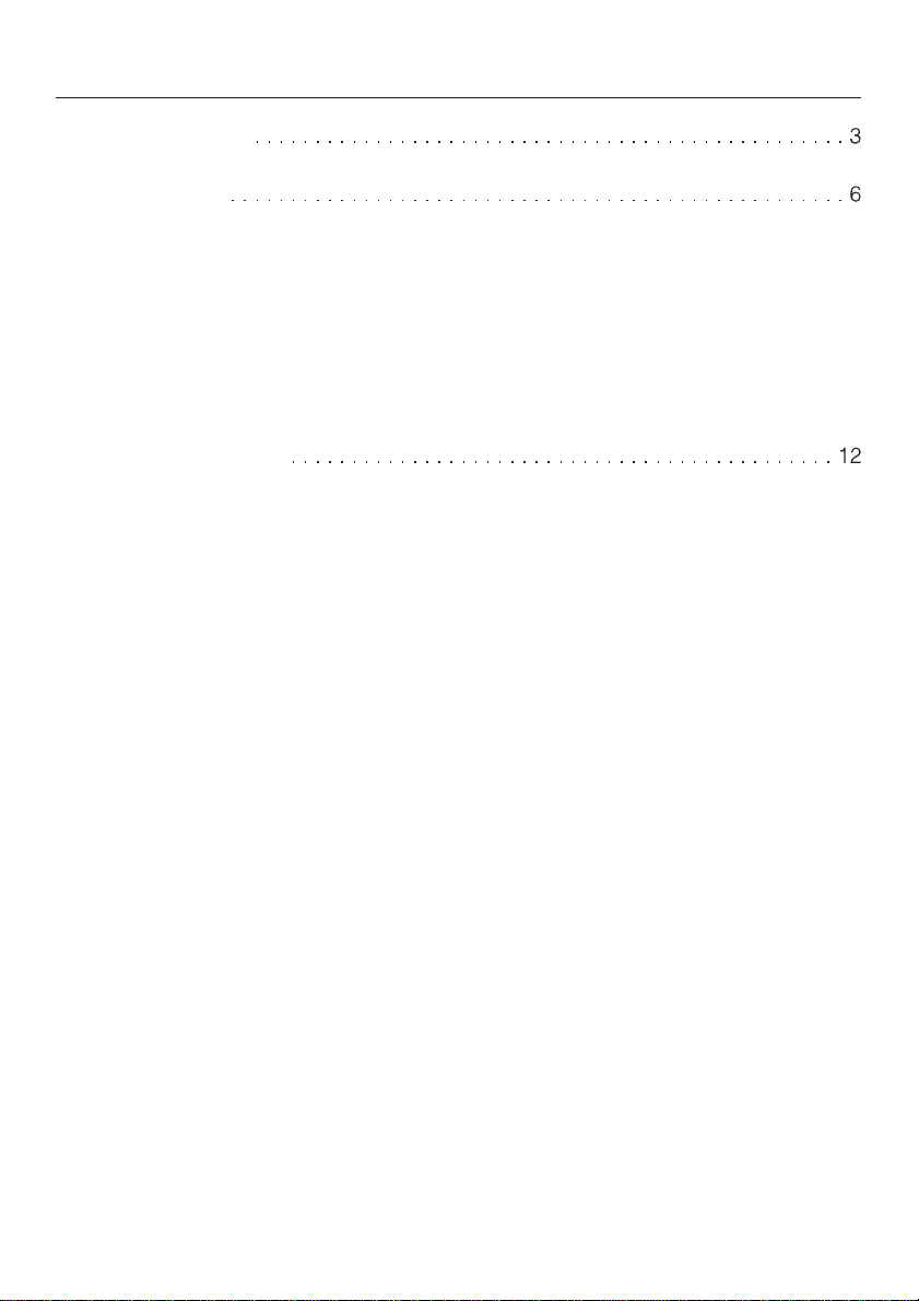
When installing a hob there may be
a wall at the back and a wall or tall
unit at one side. On the other side there
must not be a unit or wall which stands
higher than the hob.
This equipment is not designed for
maritime use or for use in mobile
installations such as caravans, aircraft
etc. However it may be suitable for
such usage subject to a risk
assessment of the installation being
carried out by a suitably qualified
engineer.
Safety instructions
recommended
not recommended
a A minimum safety distance of
50 mm must be maintained between
the cut-out and an adjacent wall
and/or tall unit except if these are of
a non-combustible material.
See: Installation of appliance on wall
with additional niche cladding
not allowed
3
Safety instructions
These hobs must not be installed
above ovens or cookers unless
these have a built-in cooling down fan.
If the hob is built in above a
pyrolytic oven or cooker, it must not
be used during the pyrolytic cleaning
process.
To ensure adequate ventilation for
the electronic unit on the hob an
interim shelf must not be fitted
underneath hobs with induction
heating.
Spray canisters, aerosols and other
inflammable substances should not
be stored in a drawer under the hob.
After installation of the hob ensure
that the connection cable is without
hindrance and that there is no
mechanical obstruction which could
damage it such as a drawer.
These appliances must not be
installed over a dishwasher,
washing machine, tumble dryer,
refrigerator or freezer. The high
temperatures radiated by hobs could
damage the appliance below.
All dimensions in this instruction booklet
are given in mm.
Keep these instructions in a safe place
and pass them on to any future owner
of the appliance.
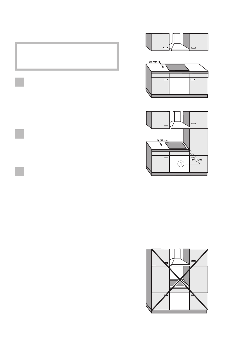
Safety distance above
appliances
A minimum safety distance b must be
maintained between the hob and a
cooker hood above it. See the
manufacturer’s operating and
installation instructions for details. For
any flammable objects, e.g. utensil rails
etc. a minimum safety distance of 760
mm should be maintained between it
and the hob below.
When two or more appliances are
installed together below a cooker
hood, e.g. an electric hob and a gas
wok combiset, which have different
safety distances given in their
installation instructions you should
select the greater distance of the
two.
4
Safety instructions
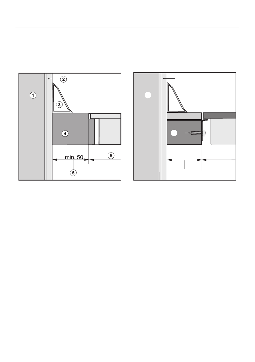
Installation of appliance on wall with additional niche cladding
Hob with frame Flush fit hob
c
b
d
e
e
min. 50
f
g
a Masonry
b Niche cladding
c Upstand
d Worktop
e Worktop cut-out
f 50 mm minimum distance between niche cladding and the worktop cut-out.
This distance is only necessary when the niche cladding material is wood or
any other combustible material. For non-combustible materials (metal, ceramic
tiles or similar) this dimension can be reduced by the thickness of the niche
cladding material. The materials can warp or distort when subjected to high
temperatures.
5

Hobs with frame
Appliance dimensions and worktop cut-out
KM 490 / KM 490-1
574
8
58
43
8
504
c
b
max.R4
+
-1
490
75
75
560
+
1
-
a Spring clamps
b Building in height including electrical connection box at the back right approx.
58 mm.
min.50
b
6

KM 493 / KM 493-1
Hobs with frame
a Spring clamps
b Building in height including electrical connection box at the back right approx.
58 mm.
7

Hobs with frame
KM 496
a Spring clamps
b Building in height
c Building in height including electrical connection box
d Front
8

Preparing the worktop
Make the worktop cut-out following
^
the dimensions applicable.
Remember to maintain a minimum
safety distance of 50 mm from the
back wall, as well as from any side
wall to the right or left of the hob. See
"Safety instructions".
Seal the cut surfaces with a suitable
^
heat-resistant sealant to avoid
swelling caused by moisture.
The materials used must be
heat-resistant.
Hobs with frame
If, during installation, you find that
the seals on the corners of the frame
are not flush with the worktop, the
corner radius ß R4, can be carefully
scribed to suit.
9

Hobs with frame
Positioning the spring clamps
Worktops made of wood, Corian and
Askilan etc.
75
b
^ Position the spring clamps (supplied)
a in the positions shown (see
“Appliance dimensions and worktop
cut-out”) so that they are flush with
the top edge of the cut-out, and
secure with the 3.5 x 25 mm screws
supplied.
Granite and marble worktops
75
f
a
g
f
10
a
^
With granite worktops, the spring
clamps a must be positioned and
secured with strong double-sided
adhesive tape. In addition coat the
edges of the spring clamps with
silicone.
The screws are not required for granite
worktops.

Installing the hob
Feed the hob connection cable down
^
through the cut-out.
^ Lightly position the hob on the spring
clamps a.
^ Using both hands, press down
evenly on the sides of the hob until it
clicks into position. When doing this
make sure that the seal under the
hob sits flush with the worktop on all
sides. This is important to ensure an
effective seal all round. Do not use
sealant.
^
Connect the hob to the mains.
^
Check that the hob works.
Hobs with frame
Do not use any sealant unless
expressly instructed to do so. The
sealing strip under the edge of the top
part of the hob provides a sufficient
seal for the worktop.
Do not use sealant between the
frame of the top part of the hob and
the worktop.
This could cause difficulties if the
hob ever needs to be taken out for
servicing and possibly result in
damage to the hob frame or the
worktop.
The hob can now only be removed
with a special tool.
11

Electrical connection
All electrical work should be carried
out by a suitably qualified and
competent person, in strict
accordance with national and local
safety regulations.
Test marks Electrical safety,
C-Tick Mark
Electrically suppressed according to
AS/NZS 1044
Important
Installation, repairs and other work
by unqualified persons could be
dangerous. The manufacturer
cannot be held liable for
unauthorised work.
Ensure power is not supplied to the
appliance while installation work is
being carried out.
The appliance must only be
operated when built-in. This is to
ensure that all electrical parts are
shielded. Live parts must not be
exposed.
After the appliance has been built in,
a check must be made that all
electrical parts are shielded.
The voltage and rated load are given
on the data plate. Ensure that these
match the household mains supply.
Connection should be made via a
suitable isolator, which complies with
national and local safety regulations
and which is easily accessible after the
appliance has been built in.
For extra safety it is advisable to install
a residual current device (RCD), with a
trip current of 30 mA.
The appliance is supplied for
connection to an a.c. single phase
230-240 V, 50 Hz supply with a 3-core
cable.
The wires in the mains lead are
coloured in accordance with the
following code:
Green/yellow = earth
Blue = neutral
Brown = live
WARNING
THIS APPLIANCE MUST BE
EARTHED
The electrical safety of this appliance
can only be guaranteed when
continuity is complete between the
appliance and an effective earthing
system, which complies with local and
national regulations. It is most important
that this basic safety requirement is
regularly tested and if there is any
doubt, the electrical wiring in the home
should be inspected by a qualified
electrician. The manufacturer cannot be
held liable for the consequences of an
inadequate earthing system such as an
electric shock.
The manufacturer cannot be held
liable for damage which is the direct
or indirect result of incorrect
installation or connection.
12

Connection diagram
Electrical connection
Warning
This appliance must only be connected
to a 230 V or 240 V supply using the
connection cable supplied in the
accessory pack.
Connection must be made in
accordance with the wiring diagram.
The earth lead must be connected.
131415


Alteration rights reserved / 2204
This paper consists of cellulose which has been bleached without the use of chorine
M.-Nr. 05 619 451 / 01
en - AUS
 Loading...