

Page 1
Installation instructions
Ceramic hobs
KM 460 / KM 461 / KM 463
KM 464 / KM 465 / KM 466
KM 468 / KM 469
To avoid the risk of accidents
or damage to the machine
it is essential to read these
instructions before it is installed
or used for the first time.
GiZHWOr
M.-Nr. 05 397 194
Page 2

Contents
Safety instructions. . . . . . . . . . . . . . . . . . . . . . . . . . . . . . . . . . . . . . . . . . . . . . . . . 3
Installation . . . . . . . . . . . . . . . . . . . . . . . . . . . . . . . . . . . . . . . . . . . . . . . . . . . . . . . . 3
Safety distance above the appliance . . . . . . . . . . . . . . . . . . . . . . . . . . . . . . . . . . . 4
Installation of appliance on wall with additional niche cladding . . . . . . . . . . . . . . . 5
Appliance dimensions and worktop cut-out . . . . . . . . . . . . . . . . . . . . . . . . . . . 6
KM 460 / KM 461 . . . . . . . . . . . . . . . . . . . . . . . . . . . . . . . . . . . . . . . . . . . . . . . . . . . 6
KM 463. . . . . . . . . . . . . . . . . . . . . . . . . . . . . . . . . . . . . . . . . . . . . . . . . . . . . . . . . . . 7
KM 464. . . . . . . . . . . . . . . . . . . . . . . . . . . . . . . . . . . . . . . . . . . . . . . . . . . . . . . . . . . 8
KM 465 / KM 466 . . . . . . . . . . . . . . . . . . . . . . . . . . . . . . . . . . . . . . . . . . . . . . . . . . 10
KM 468. . . . . . . . . . . . . . . . . . . . . . . . . . . . . . . . . . . . . . . . . . . . . . . . . . . . . . . . . . 11
KM 469. . . . . . . . . . . . . . . . . . . . . . . . . . . . . . . . . . . . . . . . . . . . . . . . . . . . . . . . . . 12
Installation . . . . . . . . . . . . . . . . . . . . . . . . . . . . . . . . . . . . . . . . . . . . . . . . . . . . . . 14
Fitting the spring clamps and safety brackets . . . . . . . . . . . . . . . . . . . . . . . . . . . 14
Installing the appliance. . . . . . . . . . . . . . . . . . . . . . . . . . . . . . . . . . . . . . . . . . . 14
Granite worktops . . . . . . . . . . . . . . . . . . . . . . . . . . . . . . . . . . . . . . . . . . . . . . . . . . 15
Installing the appliance in granite worktops. . . . . . . . . . . . . . . . . . . . . . . . . . . 16
Important . . . . . . . . . . . . . . . . . . . . . . . . . . . . . . . . . . . . . . . . . . . . . . . . . . . . . . . . 16
Electrical connection. . . . . . . . . . . . . . . . . . . . . . . . . . . . . . . . . . . . . . . . . . . . . . 17
Electrical connection AUS/NZ . . . . . . . . . . . . . . . . . . . . . . . . . . . . . . . . . . . . . . . . 18
Wiring diagram . . . . . . . . . . . . . . . . . . . . . . . . . . . . . . . . . . . . . . . . . . . . . . . . . . . 19
2
Page 3
Installation
Safety instructions
Fit wall units and extractor hood be
fore fitting the hob, to avoid damag
ing the ceramic surface.
The veneer or laminate coating of
worktops (or adjacent kitchen
units) must be treated with 100°C
heat-resistant adhesive which will not
dissolve or distort.
Any backmoulds must be of heat-resis
tant material.
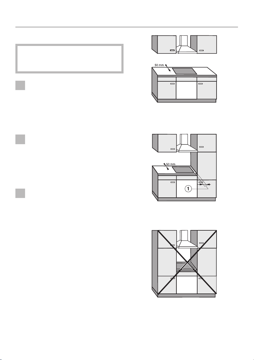
Ideally the hob should be installed
with plenty of space on either side.
There may be a wall at the rear and a
tall unit or wall at one side. On the other
side, however, no unit or divider should
stand higher than the hob (see illustrations).
This equipment is not designed for
maritime use or for use in mobile
installations such as caravans, aircraft
etc. However it may be suitable for
such usage subject to a risk assess
ment of the installation being carried
out by a suitably qualified engineer.
-
-
-
recommended
-
possible, but not recommended
a Minimum distance between
cut-out and tall unit/wall = 50 mm,
unless they are made from a
non-combustible material.
See: Installation of appliance on
wall with additional niche cladding.
not allowed
3
Page 4
Safety instructions
Spray canisters, aerosols and other
inflammable substances should not
be stored in a drawer under the hob un
less there is a shelf separating the
drawer from the hob. If cutlery inserts
are to be placed in the drawer, these
must be made of a suitable heat-resis
tant material.
The hob may not be built in over a
fridge, fridge-freezer, freezer, dish
washer, washing machine or tumble
dryer.
After installing the hob, ensure that
the connection cable cannot come
into contact with the underside of the
appliance. Make sure that there is no
mechanical obstruction, such as a
drawer, which could damage it.
Keep these instructions in a safe place
and pass them on to any future owner
of the appliance.
All dimensions in this instruction booklet
are given in mm.
-
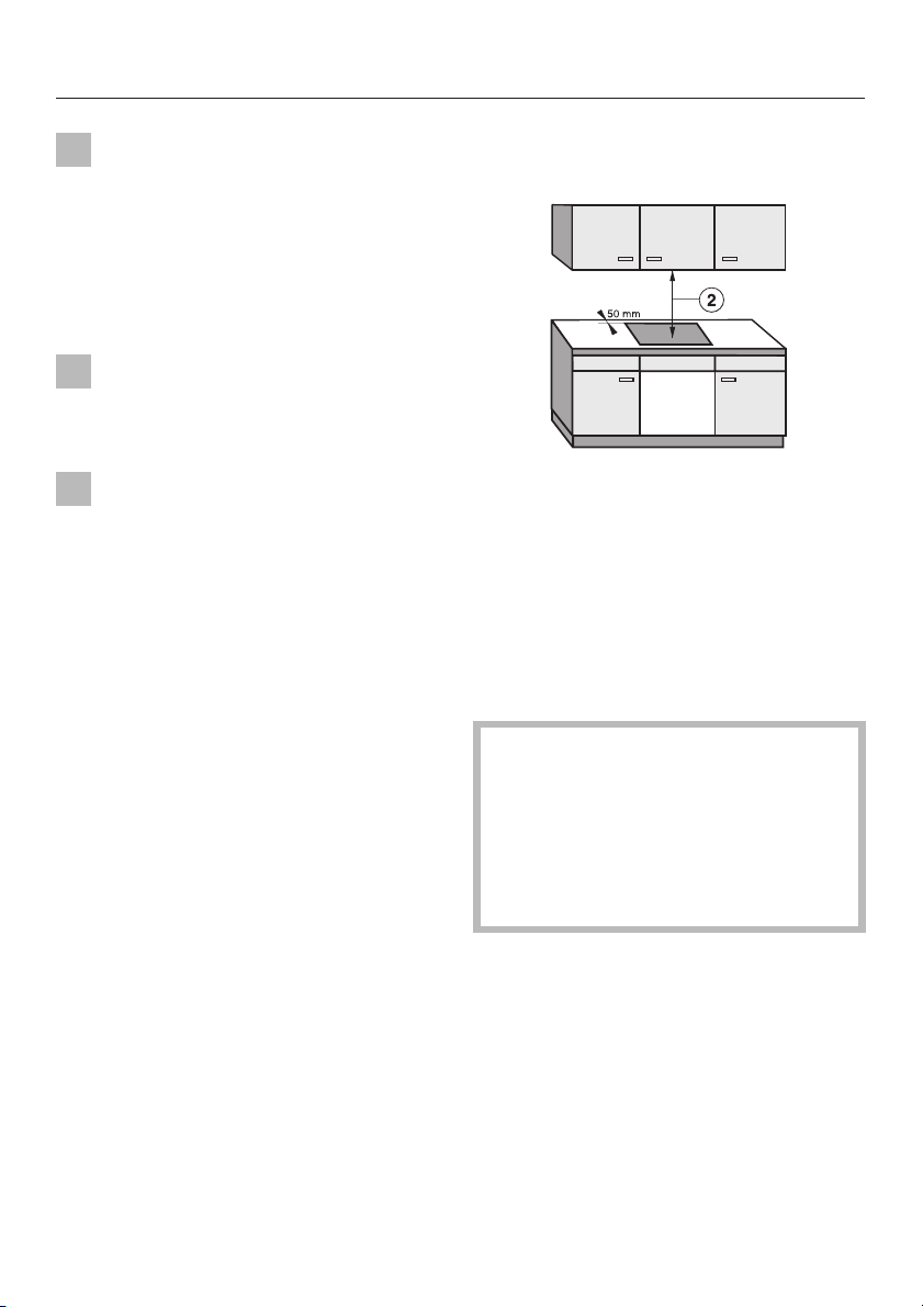
Safety distance above the
appliance
-
-
b A minimum safety distance must be
maintained between the hob and a
cooker hood above it. See the manufacturer’s operating and installation
instructions for details. For any flammable objects, e.g. utensil rails etc. a
minimum safety distance of 760 mm
should be maintained between it and
the hob below.
When two or more appliances are installed together below a cooker
hood, e.g. an electric hob and a gas
wok combiset, which have different
safety distances given in their instal
lation instructions you should select
the greater distance of the two.
-
4
Page 5
Safety instructions
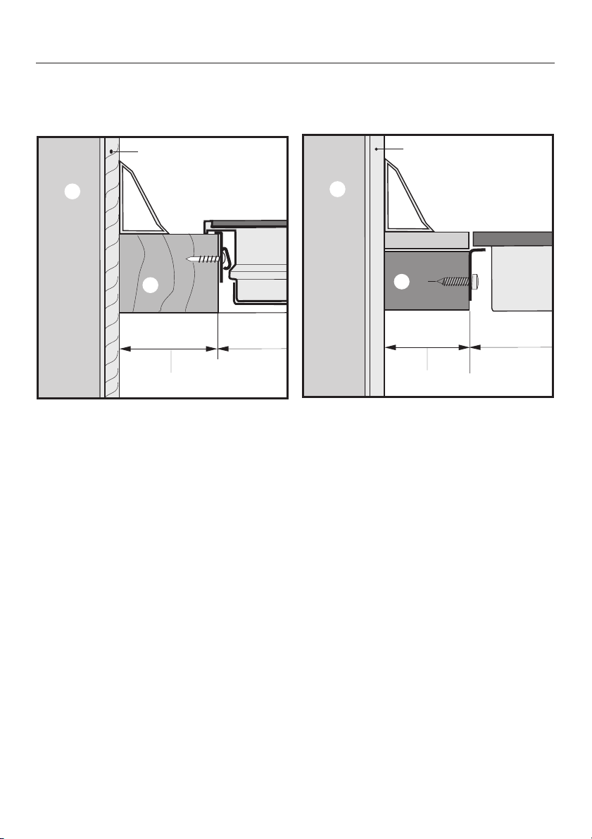
Installation of appliance on wall with additional niche cladding
c
b
b
d
e
min. 50
f
g
Hob with frame/bevel edge Flush fit hob
a Masonry
b Niche cladding
c Upstand
d Worktop
e Worktop cut-out
d
e
c
e
min. 50
g
f
f 50 mm minimum distance between niche cladding and the worktop cut-out.
This distance is only necessary for niche cladding made of wood or any other
combustible material. For non-combustible materials (metal, ceramic tiles or
similar), this dimension can be reduced by the thickness of the niche cladding
material. The materials can warp or distort when subjected to high tempera
tures.
-
5
Page 6
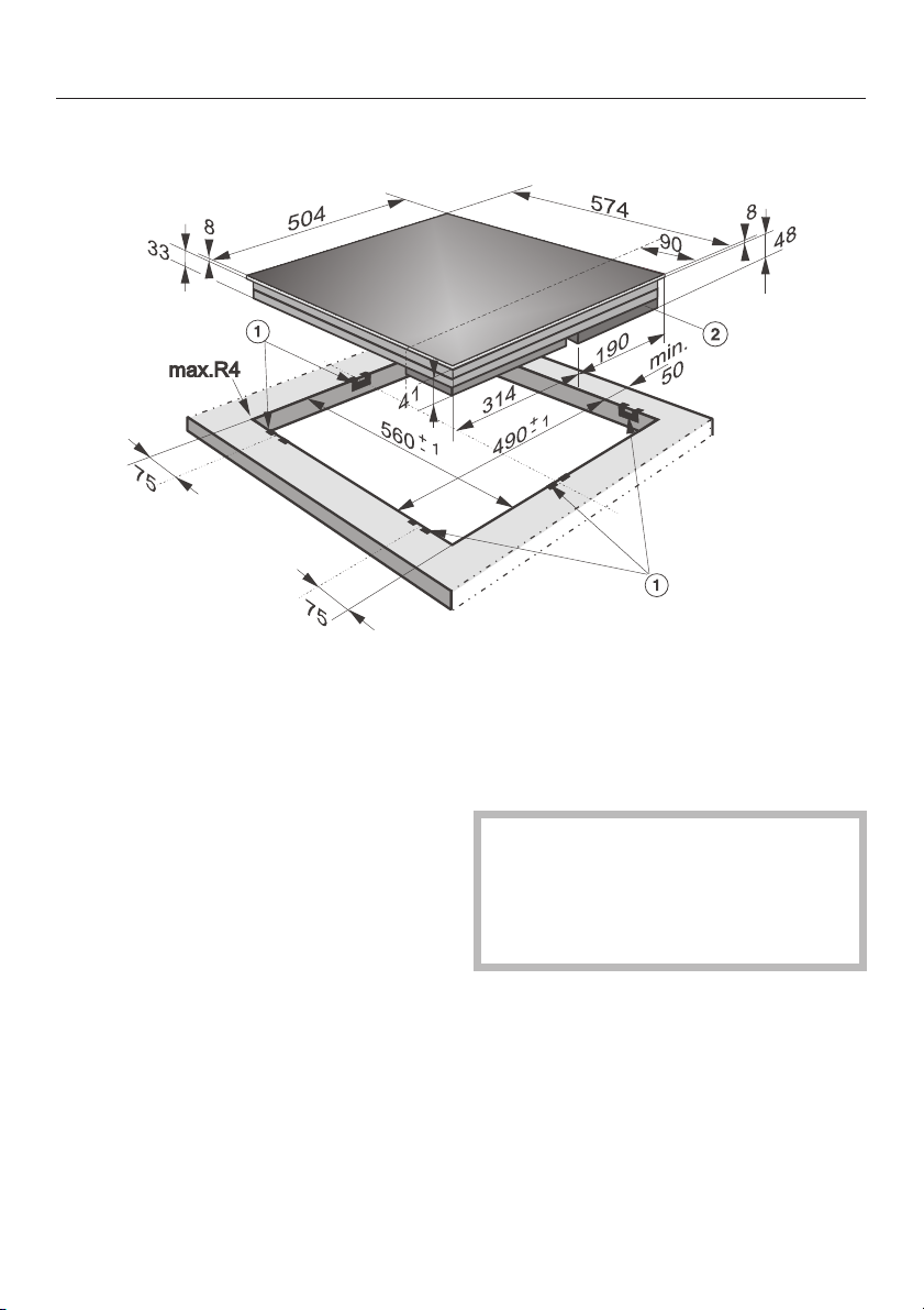
Appliance dimensions and worktop cut-out
KM 460 / KM 461
a Spring clamps
^
Make the worktop cut-out following
the dimensions shown above.
^
Remember to maintain a minimum
safety distance of 50 mm between
the hob and the back wall and a side
wall to the right or left of the hob. See
"Warning and Safety instructions".
^
Seal the cut surfaces with a suitable
sealant to avoid swelling caused by
moisture.
The materials used must be heat re
sistant.
6
b Depth for building in including the
electrical connection box located at
the rear on the right hand side
approx. 48 mm.
If during installation the corners of
the frame are not flush with the
worktop surface, the corner radius,
Max R4 can be carefully scribed to
suit.
-
Page 7
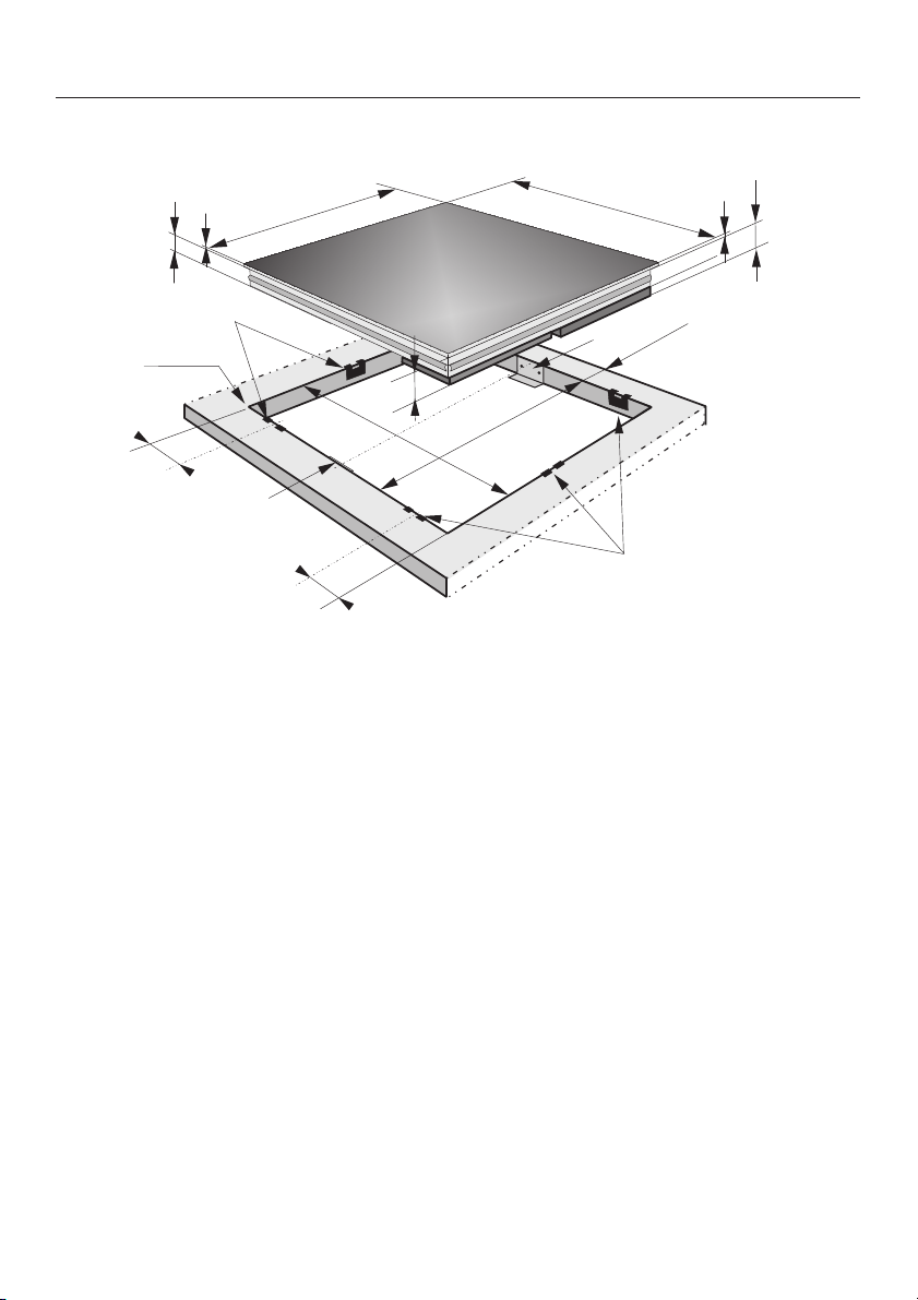
KM 463
Appliance dimensions and worktop cut-out
a Spring clamps
^
Make the worktop cut-out following
the dimensions shown above.
^
Remember to maintain a minimum
safety distance of 50 mm between
the hob and the back wall and a side
wall to the right or left of the hob. See
"Warning and Safety instructions".
^
Seal the cut surfaces with a suitable
sealant to avoid swelling caused by
moisture.
The materials used must be heat re
sistant.
b Depth for building in including the
electrical connection box located at
the rear on the right hand side
approx. 48 mm.
If during installation the corners of
the frame are not flush with the
worktop surface, the corner radius,
Max R4 can be carefully scribed to
suit.
-
7
Page 8
Appliance dimensions and worktop cut-out
KM 464
36
5
520
a
max.R4
44
560
75
e
75
a Spring clamps
b Depth for building in including the
electrical connection box located at
the rear on the right hand side
approx. 51 mm.
c Height above worktop
590
c
5
51
b
e
min.50
1
+
+
1
-
-
490
a
e Safety bracket
^
Make the worktop cut-out following
the dimensions shown above.
^
Remember to maintain a minimum
safety distance of 50 mm between
the hob and the back wall and a side
wall to the right or left of the hob. See
"Warning and Safety instructions".
8
^
Seal the cut surfaces with a suitable
sealant to avoid swelling caused by
moisture.
The materials used must be heat re
sistant.
-
Page 9

Appliance dimensions and worktop cut-out
Protective base
A protective base must be installed
^
underneath the hob. There must be a
gap of at least 15 mm between the
hob and the base (see illustration).
If during installation the corners of
the frame are not flush with the
worktop surface, the corner radius,
Max R4 can be carefully scribed to
suit.
15
min.
10
50
9
Page 10

Appliance dimensions and worktop cut-out
KM 465 / KM 466
a Spring clamps
^ Make the worktop cut-out following
the dimensions shown above.
^
Remember to maintain a minimum
safety distance of 50 mm between
the hob and the back wall and a side
wall to the right or left of the hob. See
"Warning and Safety instructions".
^
Seal the cut surfaces with a suitable
sealant to avoid swelling caused by
moisture.
The materials used must be heat re
sistant.
10
b Depth for building in including the
electrical connection box located at
the rear on the right hand side
approx. 53 mm.
If during installation the corners of
the frame are not flush with the
worktop surface, the corner radius,
Max R4 can be carefully scribed to
suit.
-
Page 11

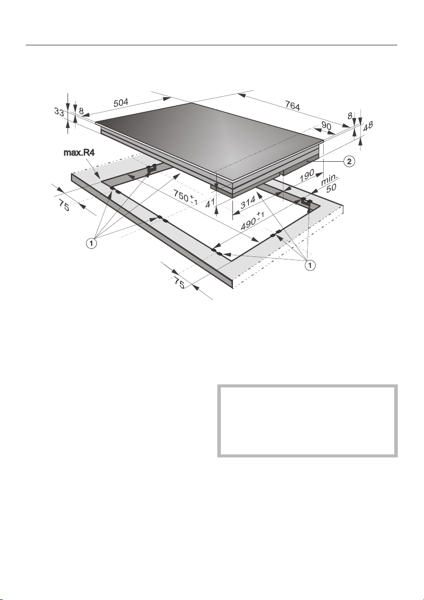
KM 468
Appliance dimensions and worktop cut-out
38
3
max.R4
75
504
750
+
a
75
a Spring clamps
^ Make the worktop cut-out following
the dimensions shown above.
^
Remember to maintain a minimum
safety distance of 50 mm between
the hob and the back wall and a side
wall to the right or left of the hob. See
"Warning and Safety instructions".
^
Seal the cut surfaces with a suitable
sealant to avoid swelling caused by
moisture.
The materials used must be heat re
sistant.
764
3
90
53
b
190
min.
0
5
490
+
-
314
1
46
-
1
a
b Depth for building in including the
electrical connection box located at
the rear on the right hand side
approx. 53 mm.
If during installation the corners of
the frame are not flush with the
worktop surface, the corner radius,
Max R4 can be carefully scribed to
suit.
-
11
Page 12

Appliance dimensions and worktop cut-out
KM 469
36
max. R4
520
750
44
+
1
-
490
314
+
-
780
5
190
1
e
a
Position of spring clamps and safety brackets on KM 469
300
75
75
e
a
a
90
min.
50
a
c
5
51
b
75
e
75
300
a Spring clamps
b Depth for building in including the electrical connection box located at the rear
on the right hand side approx. 51 mm.
c Height above worktop
e Safety bracket
12
Page 13

Appliance dimensions and worktop cut-out
Make the worktop cut-out following
^
the dimensions shown above.
Remember to maintain a minimum
^
safety distance of 50 mm between
the hob and the back wall and a side
wall to the right or left of the hob. See
"Warning and Safety instructions".
Seal the cut surfaces with a suitable
^
sealant to avoid swelling caused by
moisture.
The materials used must be heat re
sistant.
Protective base
min.
50
If during installation the corners of
the frame are not flush with the
worktop surface, the corner radius,
Max R4 can be carefully scribed to
suit.
-
15
^
A protective base must be installed
underneath the hob. There must be a
gap of at least 15 mm between the
hob and the base (see illustration).
10
13
Page 14

Installation
Fitting the spring clamps and
safety brackets
75
b
Installing the appliance
Feed the connection cable down
^
through the cut-out.
^ Lightly position the hob on the spring
clamps a .
^ Using both hands press down evenly
on the sides of the hob until it clicks
into position. When doing this make
sure that the seal under the hob sits
flush with the worktop on all sides.
This is important to ensure an effective seal on all sides. The hob can
now only be removed with a special
tool.
e
^
Position the spring clamps a and the
safety brackets e supplied in the
positions shown in the illustrations in
"Appliance dimensions and Worktop
cut-out" pages by placing them on or
flush with the the upper edge of the
cut-out as shown above, and then se
cure them with the 3.5 x 25 mm
screws supplied.
14
^
Now connect the connection cable to
the mains power supply. See "Electri
cal connection".
-
-
Page 15

Granite worktops
Installation
On granite worktops the spring clamps a and safety brackets e must be posi
tioned and secured using double-sided adhesive tape f. In addition coat the
edges of the spring clamps and safety brackets with silicone sealant g .
The screws are not required for granite worktops.
f
e
-
e
g
15
Page 16

Installation
Installing the appliance in granite
worktops
Feed the connection cable down
^
through the cut-out.
^ Lightly position the hob on the spring
clamps a.
^ Using both hands press down evenly
on the sides of the hob until it clicks
into position. When doing this make
sure that the seal under the hob sits
flush with the worktop on all sides.
This is to ensure a thorough seal is
provided all round.
The hob can now only be removed
with a special tool.
^
Now connect the connection cable to
the mains power supply. See "Electri
cal connection".
Important
Do not let sealant get in between the
frame of the top part of the hob and
the worktop.
This could cause difficulties if the
hob ever needs to be taken out for
servicing and possibly result in damage to the hob frame or the worktop.
The sealing strip under the edge of the
top part of the hob provides a sufficient
seal for the worktop.
-
16
Page 17

All electrical work should be carried
out by a suitably qualified and com
petent person, in strict accordance
with national and local safety regula
tions.
Installation, repairs and other work
by unqualified persons could be
dangerous. The manufacturer can
not be held responsible for un
authorised work.
Ensure power is not supplied to the
appliance while installation work is
being carried out.
The appliance must only be operated when built-in. This is to ensure
that all electrical parts are shielded.
Live parts must not be exposed.
-
-
Electrical connection
When switched off there must be an
all-pole contact gap of at least 3 mm in
-
the isolator switch (including switch,
fuses and relays according to EN 60
-
335).
Important U.K.
The appliance is supplied for connec
tion to an a.c. single phase 230-240 V,
50 Hz supply with a 3-core cable.
The wires in the mains lead are col
oured in accordance with the following
code:
Green/yellow = earth
Blue = neutral
Brown = live
WARNING
THIS APPLIANCE MUST BE
EARTHED
-
-
The voltage, rated load and fusing are
given on the dataplate. Ensure that
these match the household mains sup
ply.
Connection should be made via a suit
able isolator which complies with na
tional and local safety regulations, and
the On/Off switch should be easily ac
cessible after the appliance has been
built in.
For extra safety it is advisable to install
a residual current device (RCD), with a
trip current of 30 mA (in accordance
with DIN VDE 0664, VDE 0100 Section
739).
-
-
-
The electrical safety of this appliance
can only be guaranteed when continuity is complete between the appliance
and an effective earthing system, which
complies with local and national regula
tions. It is most important that this basic
safety requirement is tested by a quali
fied electrician. The manufacturer can
not be held responsible for the conse
quences of an inadequate earthing sys
tem such as an electric shock.
The manufacturer cannot be held lia
ble for damage which is the direct or
indirect result of incorrect installation
or connection.
-
-
-
-
-
-
17
Page 18

Electrical connection
Electrical connection AUS/NZ
All electrical work should be carried out
by a competent person, in strict accor
dance with national and local safety
regulations.
The voltage and rated load are given
on the data plate. Please ensure that
these match the household mains sup
ply.
After the appliance has been built in, a
check must be made that all electrical
parts are shielded.
Connection for each appliance should
be made via a suitable isolator, which
complies with national and local safety
regulations and which is accessible after the appliance has been built in. For
extra safety it is advisable to install a residual current device (RCD), with a trip
current of 30 mA.
Ensure power is not restored to the ap
pliance while installation work is being
carried out.
Test marks Electrical safety,
C-Tick Mark
Electrically suppressed according to
AS/NZS 1044
-
-
Important
The wires in the mains lead are col
oured in accordance with the following
code:
Green/yellow = earth
Blue = neutral
Brown = live.
WARNING:
THIS APPLIANCE MUST BE
EARTHED
18
-
Page 19

Wiring diagram
Electrical connection
N.B. This appliance is supplied single phase only in the U.K. / AUS / NZ
1920212223
Page 20

Page 21

Page 22

Page 23

Page 24

Alteration rights reserved / 0303
M.-Nr. 05 397 194 / V00
This paper consists of cellulose which has been bleached without the use of chlorine.
 Loading...