

Page 1
Installationsplan / Installation plan
Installatietekening Plano de instalación Asennusohje
Plan d`installation Plano de instalação Installasjonsplan
Pianta di installazione Σχέδιο εγκατάστασης Installationsplan
USA
G 7899
Materialnummer / Mat. no. 9510100
Änderungsstand / Version 00
Änderungsnr. / Alteration number A24364
Datum Zeichnung / Drawing Date 01.01.2013
Datum Legende / Legend Date 01.01.2013
Freigabe
/
Approval Name: Leifeld
Name: Götza
Installationsplan G 7899
Stand: 01.01.2013
Seite 1
Page 2
Technical Data Sheet
Washer-Disinfector
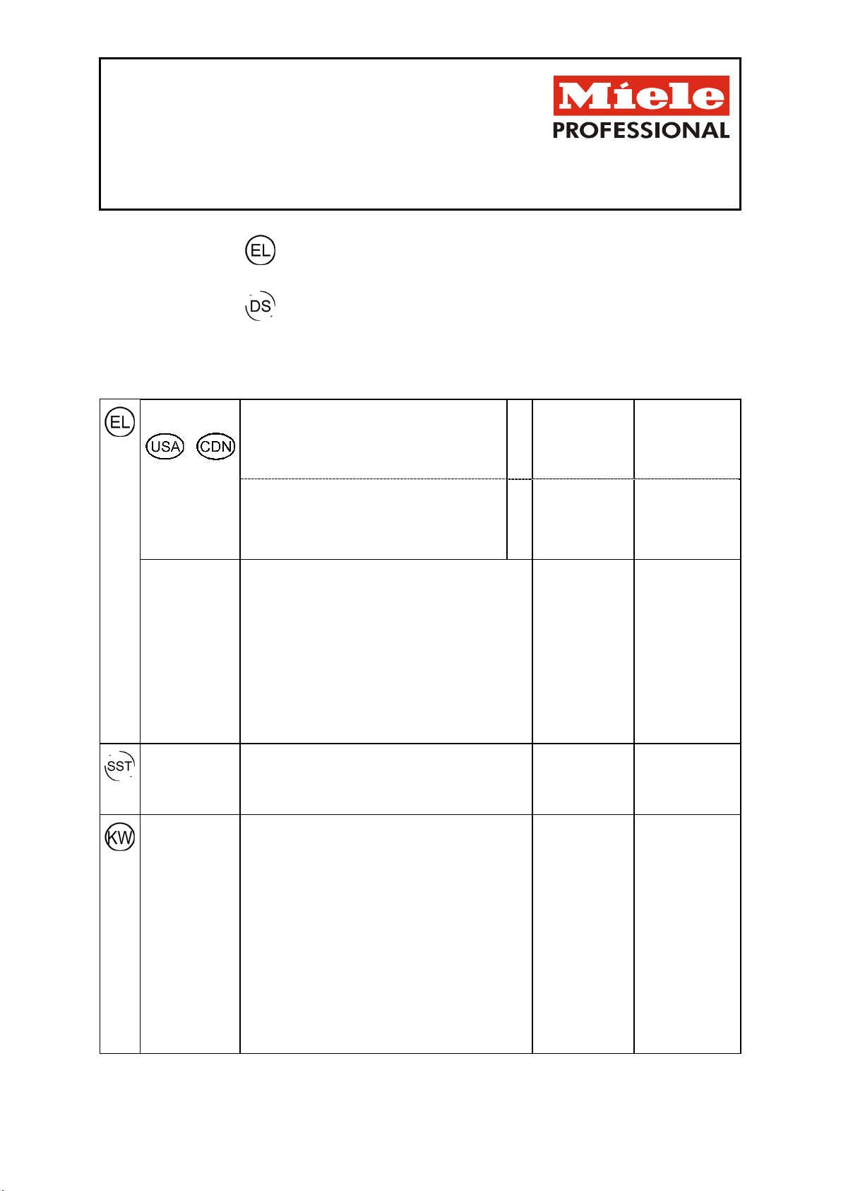
Legend:
Circled, bold-type abbreviations:
Connection required
G 7899
USA
Abbreviations surrounded by broken circle:
Connection optional
Electrical
connection
Voltage
Rated load 6.0 kW 6.0 kW
Fuse rating 3 x 20 A 3 x 20 A
Minimum cross-section 4 x 12 AWG 4 x 12 AWG
Length of electrical cord without plug 6‘ 1.9 m
It is recommended to make electrical connection via
8. Voltage (as supplied)
Rated load 6.0 kW 6.0 kW
Fuse rating 2 x 30 A 2 x 30 A
Minimum cross-section 3 x 10 AWG 3 x 10 AWG
Length of electrical cord without plug 6‘ 1.9 m
a plug and socket so that electrical safety checks
can be carried out easily. The socket must be
accessible after machine installation.
With a fixed installation, this must be via a main
switch to be provided on site, which must totally
isolate the machine from the mains with a contact
gap of at least 3 mm.
The use of a grounded leakage circuit breaker
(ELCB) is strongly recommended.
If necessary, an equipotential bond with good contact
connection must be provided in accordance with all
appropriate national and local regulations.
AC 208/60 V/Hz AC 208/60 V/Hz
3 AC 208/60 V/Hz 3 AC 208/60 V/Hz
Convertible
Interface (SST) Serial interface for output of process data provided as
A 9-pole sub D plug (male) is located on the rear of the
Cold water Two cold water connections required on models with
Max. temperature 68 °F 20 °C
Max. water hardness 64 gpg 60 °dH
Min. flow pressure 36 PSI 250 kPa
Min. flow pressure with extended fill time 15 PSI 100 kPa
Max. pressure 150 PSI
Throughput 2 gal/min 7,5 l/min
Connection thread (on site) 11.5 NH ¾“ external
Length of connection hose (supplied) 5’ 1500 mm
Length of steam condenser connection hose (supplied) 5’ 1500 mm
standard.
machine.
steam condenser (DK).
Second cold water inlet hose can be connected using Ypiece supplied.
1000 kPa
Installationsplan G 7899
Stand: 01.01.2013
Seite 2
Page 3

Demineralized
water
Max. pressure 150 PSI 1000 kPa
Throughput 2.1 gal/min 8 l/min
Connection thread (on site) 11.5 NH ¾“ external
Length of connection hose (supplied) 5’ 1500 mm
If demineralised water is not available, do not connect
Drain water Two drain hoses provided.
Drain hose (Int. dia. × wall thickness × l)
Drain pump (supplied) 7/8“ x 1/4“ x 5‘ 22 mm x 6 mm x
Steam condenser (supplied as standard) 7/8“ x 1/4“ x 5‘ 22 mm x 6 mm x
Drain pump head height from floor level, max. 3’ 1,0 m
Max. transient throughput – Drain hose 13.2 gal/h 50 l/h
On-site hose connector (Ext. dia. × l)
Drain pump 7/8“ x 1 3/16“ 22 mm × 30 mm
Steam condenser
Min. flow pressure 36 PSI 250 kPa
Min. flow pressure with extended fill time 15 PSI 100 kPa
the demineralised water hose to the cold or hot water
supplies.
Max. temperature of drain water
1500 mm
1500 mm
7/8“ x 1 3/16“
199°F
22 mm × 30 mm
93°C
Drainage
Cool-Down
(optional)
External
dispensing
(optional)
Machine data Height with lid 33.5” 850 mm
Height without lid 32.3” 820 mm
Width 23.6” 598 mm
Depth 23.6” 600 mm
Net weight 154 lb 70 kg
Dynamic floor load 1500 N 1500 N
Min. transport width incl. pallet 28” 700 mm
Min. transport height incl. pallet 38” 950 mm
When fitting the machine in a housing unit, a suitable opening min. 5 7/8” x 4” (150 x 100 mm) must be provided for the supply
and drainage hoses.
If a new installation is being planned, the preferred niche depth is 27 9/16” (700 mm) in order to be able to lay the hoses
easily.
Installation should only be carried out by authorized installers and must comply with local and national building codes.
Observe installation instructions when installing this machine. Alteration rights reserved.
Cool-Down Solution to reduce drain temperature to
140°F.
Please allow 7” additional space in the back of the
machine.
Dispenser unit (DOS K 60) connection on rear panel
Änderungsnr. Datum Bezeichnung:
A24364 01.01.2013 Einführung
Installationsplan G 7899
Stand: 01.01.2013
Seite 3
Page 4

Page 5

 Loading...