

Page 1

Operating instructions
Washer-disinfector
G 7835 CD OXIVARIO
To avoid the risk of accidents or
damage to the machine it is
essential to read these instructions
before it is installed, commissioned
and used for the first time.
G
M.-Nr. 06 594 290
Page 2

Contents
Description of the machine. . . . . . . . . . . . . . . . . . . . . . . . . . . . . . . . . . . . . . . . . . 4
Guide to the machine. . . . . . . . . . . . . . . . . . . . . . . . . . . . . . . . . . . . . . . . . . . . . . . 6
Warning and safety instructions . . . . . . . . . . . . . . . . . . . . . . . . . . . . . . . . . . . . . 9
Opening and closing the door . . . . . . . . . . . . . . . . . . . . . . . . . . . . . . . . . . . . . . 14
Electro-thermal door lock. . . . . . . . . . . . . . . . . . . . . . . . . . . . . . . . . . . . . . . . . . . . 14
To open the door with the emergency release. . . . . . . . . . . . . . . . . . . . . . . . . . . . 14
Water softener . . . . . . . . . . . . . . . . . . . . . . . . . . . . . . . . . . . . . . . . . . . . . . . . . . . 15
Setting the water softener . . . . . . . . . . . . . . . . . . . . . . . . . . . . . . . . . . . . . . . . . . . 15
Salt indicator . . . . . . . . . . . . . . . . . . . . . . . . . . . . . . . . . . . . . . . . . . . . . . . . . . . . . 15
Filling the salt reservoir . . . . . . . . . . . . . . . . . . . . . . . . . . . . . . . . . . . . . . . . . . . . . 16
Automatic mobile unit recognition (AWK) . . . . . . . . . . . . . . . . . . . . . . . . . . . . . 17
Mobile unit coding . . . . . . . . . . . . . . . . . . . . . . . . . . . . . . . . . . . . . . . . . . . . . . . . . 17
Mobile unit coding strip . . . . . . . . . . . . . . . . . . . . . . . . . . . . . . . . . . . . . . . . . . 18
Setting mobile unit coding . . . . . . . . . . . . . . . . . . . . . . . . . . . . . . . . . . . . . . . . 18
Areas of application. . . . . . . . . . . . . . . . . . . . . . . . . . . . . . . . . . . . . . . . . . . . . . . 20
Loading the machine . . . . . . . . . . . . . . . . . . . . . . . . . . . . . . . . . . . . . . . . . . . . . . . 20
Height adjustable top basket. . . . . . . . . . . . . . . . . . . . . . . . . . . . . . . . . . . . . . . . . 22
Laboratory glassware (LG) . . . . . . . . . . . . . . . . . . . . . . . . . . . . . . . . . . . . . . . . . . 23
Surgical instruments (OP) . . . . . . . . . . . . . . . . . . . . . . . . . . . . . . . . . . . . . . . . . . . 24
Anaesthetic equipment (AN) . . . . . . . . . . . . . . . . . . . . . . . . . . . . . . . . . . . . . . . . . 25
Baby bottles (BC) . . . . . . . . . . . . . . . . . . . . . . . . . . . . . . . . . . . . . . . . . . . . . . . . . 26
Operating theatre shoes (OS) . . . . . . . . . . . . . . . . . . . . . . . . . . . . . . . . . . . . . . . . 27
Dispensing liquid chemical agents . . . . . . . . . . . . . . . . . . . . . . . . . . . . . . . . . . 28
Preparing the DOS dispensers . . . . . . . . . . . . . . . . . . . . . . . . . . . . . . . . . . . . . . . 28
Fill the containers with the relevant agent . . . . . . . . . . . . . . . . . . . . . . . . . . . . 29
Connecting the H
Venting the dispensing system . . . . . . . . . . . . . . . . . . . . . . . . . . . . . . . . . . . . . . . 31
Dispensing system maintenance. . . . . . . . . . . . . . . . . . . . . . . . . . . . . . . . . . . . . . 31
External Dispensing systems. . . . . . . . . . . . . . . . . . . . . . . . . . . . . . . . . . . . . . . . . 31
solution container. . . . . . . . . . . . . . . . . . . . . . . . . . . . . . 30
2O2
2
Page 3

Contents
Operation . . . . . . . . . . . . . . . . . . . . . . . . . . . . . . . . . . . . . . . . . . . . . . . . . . . . . . . 32
Switching on . . . . . . . . . . . . . . . . . . . . . . . . . . . . . . . . . . . . . . . . . . . . . . . . . . . . . 32
Changing the operating level . . . . . . . . . . . . . . . . . . . . . . . . . . . . . . . . . . . . . . . . 32
Starting a programme . . . . . . . . . . . . . . . . . . . . . . . . . . . . . . . . . . . . . . . . . . . . . . 33
Programme sequence . . . . . . . . . . . . . . . . . . . . . . . . . . . . . . . . . . . . . . . . . . . . . . 34
Switching off. . . . . . . . . . . . . . . . . . . . . . . . . . . . . . . . . . . . . . . . . . . . . . . . . . . . . . 34
To change or cancel a programme . . . . . . . . . . . . . . . . . . . . . . . . . . . . . . . . . . . . 35
Interrupting a programme . . . . . . . . . . . . . . . . . . . . . . . . . . . . . . . . . . . . . . . . . . . 36
Data transfer. . . . . . . . . . . . . . . . . . . . . . . . . . . . . . . . . . . . . . . . . . . . . . . . . . . . . 37
Cleaning and care . . . . . . . . . . . . . . . . . . . . . . . . . . . . . . . . . . . . . . . . . . . . . . . . 38
Cleaning the filters in the wash cabinet. . . . . . . . . . . . . . . . . . . . . . . . . . . . . . . . . 38
Cleaning the coarse filter . . . . . . . . . . . . . . . . . . . . . . . . . . . . . . . . . . . . . . . . . 38
Cleaning the fine, flat and micro-fine filters . . . . . . . . . . . . . . . . . . . . . . . . . . . 39
Cleaning the drain pump and non-return valve. . . . . . . . . . . . . . . . . . . . . . . . . . . 40
Cleaning the filters in the water inlet . . . . . . . . . . . . . . . . . . . . . . . . . . . . . . . . . . . 41
Cleaning the control panel. . . . . . . . . . . . . . . . . . . . . . . . . . . . . . . . . . . . . . . . . . . 41
Cleaning the front of the machine . . . . . . . . . . . . . . . . . . . . . . . . . . . . . . . . . . . . . 41
Drying unit (TA) - Maintenance . . . . . . . . . . . . . . . . . . . . . . . . . . . . . . . . . . . . . . 42
Changing the coarse filter . . . . . . . . . . . . . . . . . . . . . . . . . . . . . . . . . . . . . . . . . . . 42
Exchanging the HEPA filter . . . . . . . . . . . . . . . . . . . . . . . . . . . . . . . . . . . . . . . . . . 43
Installation . . . . . . . . . . . . . . . . . . . . . . . . . . . . . . . . . . . . . . . . . . . . . . . . . . . . . . 44
Electrical connection . . . . . . . . . . . . . . . . . . . . . . . . . . . . . . . . . . . . . . . . . . . . . 46
Plumbing. . . . . . . . . . . . . . . . . . . . . . . . . . . . . . . . . . . . . . . . . . . . . . . . . . . . . . . . 47
Technical data . . . . . . . . . . . . . . . . . . . . . . . . . . . . . . . . . . . . . . . . . . . . . . . . . . . 50
Problem solving . . . . . . . . . . . . . . . . . . . . . . . . . . . . . . . . . . . . . . . . . . . . . . . . . 51
After Sales Service . . . . . . . . . . . . . . . . . . . . . . . . . . . . . . . . . . . . . . . . . . . . . . . 52
Technical safety . . . . . . . . . . . . . . . . . . . . . . . . . . . . . . . . . . . . . . . . . . . . . . . . . . . 52
Disposal of your old appliance or machine. . . . . . . . . . . . . . . . . . . . . . . . . . . . 53
3
Page 4

Description of the machine
This Miele washer-disinfector is
capable of cleaning a wide range of
medical and laboratory products, and
disinfecting them either thermally in
temperatures up to 95 °C or
chemo-thermally in temperatures up to
65 °C with the addition of a suitable
chemical agent in accordance with
general standards of hygiene and those
required for the containing of
epidemics.
Medical products include e. g. surgical
and minimally invasive instruments,
instruments and utensils used in
anaesthetics and intensive care, etc.
Laboratory products include e.g. wide
and narrow necked flasks, conical
flasks, measuring cylinders, pipettes,
beakers, Petri dishes etc.
Follow medical and laboratory product
manufacturer's instructions on how to
process their items by machine. The
DESIN vario TD programme provides
optimum protection for rigid fibre
optics, patient systems and surgical
motor systems which have been
declared by their manufacturers as
being suitable for machine processing.
Optional drying with sterile filtered hot
air is also available.
These cleaning processes use
hydrogen peroxide under alkaline
conditions to oxidise and remove
protein soiling. The cleaning agent
used must be tenside free and have a
pH value of between 11 and 11.5.
The OXIVARIO procedure has an
alkaline main wash making it
particularly suitable for the processing
of surgical instruments where existing
procedures are not satisfactory and is
very effective for the final stage of
instrument processing.
The cleaning process is gentle enough
for instruments used in minimally
invasive surgery, including fibre optics,
where the manufacturer has declared
that they are suitable for processing
with an alkaline cleaning agent.
It is not suitable for anodised
aluminium.
Be aware that items made from alloys
containing titanium such as some
implants, do not always state the
material's compatibility. Processing
such items can result in colour
changes, rendering any coding on
them ineffective. If in doubt please
consult the manufacturer of the item.
This washer-disinfector is equipped to
run the OXIVARIO programmes. The
DOS 2 dispenser is used for the H
2O2
solution.
Two special programmes are available
for this cleaning process, OXIVARIO
PLUS and OXIVARIO.
4
Instruments processed using the
OXIVARIO PLUS or OXIVARIO
programmes must be very carefully
handled afterwards.
Page 5

Description of the machine
Areas of application:
surgical instruments,
–
with the Vario-TD programme:
–
minimally invasive instruments can
be processed immediately after
being used,
anaesthetic and intensive care
–
instruments,
baby bottles and teats,
–
operating theatre shoes,
–
laboratory products used in research
–
and production as well as in all areas
of analysis and specimen taking,
including micro-biology and
biotechnology.
Instruments should preferably be
cleaned and then thermally disinfected
using the DESIN vario TD programme.
The parameters for thermal disinfection
in accordance with prEN ISO 15883-1
are 80 °C (+ 5 °C, - 0 °C) with a 10 min.
holding time or 90 °C (+ 5 °C, - 0 °C)
with a 5 min. holding time for the
inactivation of HBV.
In the U.K., reference should be made
to your local infection control officer for
guidelines of disinfection temperatures
and holding times at temperature in
accordance with HTM 2030.
In Germany, the parameters for
disinfection of a temperature of 93 °C,
with a holding time of 10 minutes,
correspond to effective areas A and B.
These have been adopted into the
official list for disinfection of instruments
in washer-disinfectors and
decontamination units, according to
section 3.2 § 18 IfSG by the Robert
Koch Institute (RKI) in Berlin (institute
for infectious diseases and
non-communicable illnesses).
The effective areas are defined as
follows:
A = Suitable for the destruction of
vegetative bacteria, including
myco-bacteria, fungi and fungal
spores.
B = Suitable for inactivating viruses
(including HBV and HIV).
The cleaning programme must be
chosen according to the type of soiling
and product requiring processing in
order to ensure that disinfection is
carried out correctly, no residues are
left behind and that subsequent
sterilisation can take place. Medical
devices are best processed using the
DESIN vario TD programme, or one of
the OXIVARIO programmes where
applicable.
This washer-disinfector is programmed
to carry out the final rinse with mains
water or AD water (aqua destillata =
purified or de-ionised water (VE), H
O
2
pure, demineralised water, aqua
purificata or distilled water where the
application requires this standard).
The water quality is of particular
importance for applications requiring
analytically clean laboratory glassware.
The type of chemical agents used will
depend on the analysis or analytical
methods being used.
This disinfector is equipped with a
steam condenser (DHK), drying unit
(TA) and water softener as standard.
Optional:
- DOS 4 for retro-fitting
5
Page 6
Guide to the machine
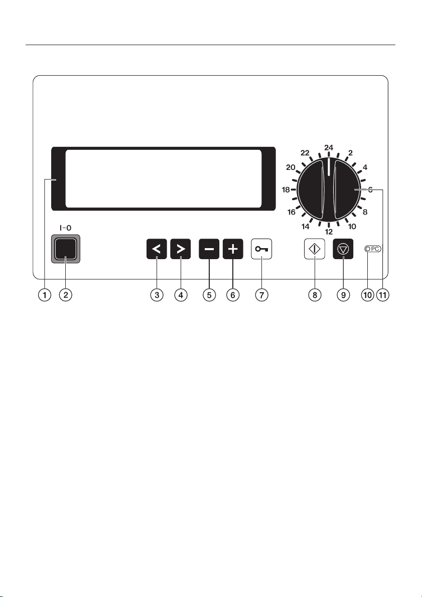
Electronic controls
a Display
with screen saver;
i.e. background lighting switches off
automatically after 15 mins.
Press any button to switch the
display back on again.
b On/Off button (I-0)
c Cursor button: left
Moves the cursor to the left:
- to the previous menu point
- to the previous parameter
- to the previous input position
d Cursor button: right
Moves the cursor to the right:
- to the next menu point
- to the next parameter
- to the next input position
6
e Minus button
– Selects programmes from position
24 upwards
– Scrolls back page by page in
menus
– Is used for entering numbers and
letters
– Alters pre-settings e.g. service
parameters
f Plus button
– Selects programmes from position
24 upwards
– Scrolls forward page by page in
menus
– Is used for entering numbers and
letters
– Alters pre-settings e.g. service
parameters
g Door switch
Page 7

Guide to the machine
h Start button
– Starts programmes
– Activates input mode
– Confirms activated values and
settings
– Confirms menu points for entry
into the relevant sub-menu
i Stop button
– Cancels a programme
– Exits from input screen without
saving
– Exits from menu screen
j Service interface
kProgramme selector
Selects programme places 1-23
7
Page 8
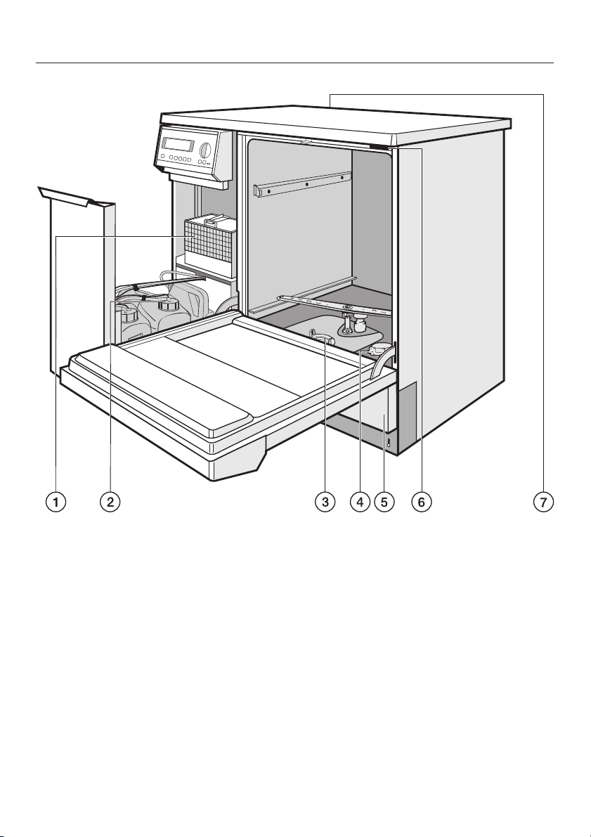
Guide to the machine
a Drying unit (TA)
b Container for neutralising agent
(red), liquid cleaning agent (blue),
hydrogen peroxide H
2O2
(black)
c Filter combination
d Salt reservoir
(for the water softener)
8
e Service panel
f Test point for validation
g Serial interface
- at the back of the machine (top left
behind the cover panel) -
Page 9

This machine complies with all
relevant legal safety requirements.
Incorrect use can lead to personal
injury and damage to property.
Read these operating instructions
carefully before starting to use this
machine. This way you will avoid the
risk of accidents and damage to the
machine.
Keep these instructions in a safe
place for reference, and pass them
on to any future user.
Correct use
Warning and safety instructions
Please pay attention to the following
notes to avoid injury and damage.
The machine should be
commissioned and then
maintained only by a Miele authorised
and trained service technician. To
ensure compliance with the Medical
Devices Directive a Miele service
contract is recommended. Repairs and
other work by unqualified persons
could be dangerous.
Do not install the machine in an
area where there is any danger of
explosion or of freezing conditions.
This washer-disinfector is designed
for specialised applications only as
described in these operating
instructions. Alterations or conversions
to the machine, or using it for purposes
other than those for which it was
designed, are not permitted and could
be dangerous.
This machine must only be used for
cleaning and disinfecting instruments
or medical products and laboratory
ware if the manufacturer has stated that
they are suitable for machine
processing. Manufacturer's cleaning
and maintenance instructions for
instruments etc. must also be
observed.
The manufacturer cannot be held liable
for damage caused by improper or
incorrect use of the machine.
This equipment may only be used
in mobile installations such as
ships, caravans, aircraft etc. if a risk
assessment of the installation has been
carried out by a suitably qualified
engineer.
The electrical safety of this
machine can only be guaranteed if
connected to a correctly installed
earthing system on site. It is most
important that this basic safety
requirement is tested regularly, and
where there is any doubt the on-site
electrical system should be inspected
by a qualified electrician.
The manufacturer cannot be held liable
for damage or injury caused by the lack
of or inadequacy of an effective
earthing system (e.g. electric shock).
A damaged machine is dangerous.
Switch off at the mains immediately
and call the Miele Service Department
or an authorised and trained Miele Ser
vice Dealer.
Personnel operating the machine
should be trained regularly.
Untrained personnel must not be
allowed access to the machine or its
controls.
This machine is not a toy! To avoid the
risk of injury never allow children to play
on or near the machine, or to operate it.
-
9
Page 10

Warning and safety instructions
Take care when handling chemical
agents such as cleaning agent,
neutralising agent, rinsing agent etc.
These may contain irritant or corrosive
ingredients. Do not use organic
solvents as these could cause an
explosion.
Follow all relevant safety procedures
carefully. Wear protective gloves and
goggles. With all chemical agents, the
manufacturer's safety instructions must
be observed.
The water in the machine must not
be used as drinking water.
Do not sit or lean on an open door.
The machine could tip up and be
damaged or cause an injury.
Be careful when sorting items with
sharp pointed ends and
positioning them in the machine that
you do not hurt yourself or create a
danger for others. Sharp knives etc.
should be placed in baskets with the
pointed ends facing downwards.
When using this machine in the
higher temperature ranges, be
especially careful not to scald or burn
yourself or come into contact with
irritant substances when opening the
door! Where disinfecting agents are
used there is a danger of inhaling toxic
fumes. Baskets, inserts and utensils
must be allowed to cool down before
they are unloaded. Any water remaining
in containers could still be very hot.
Empty them into the wash cabinet
before taking them out.
After using the hot air drying unit
open the door to allow the
everything in the cabinet from the load
itself to the mobile units, modules and
inserts to cool down.
Do not touch the heating elements
if you open the door during or
directly after the end of a programme;
you could burn yourself. They remain
hot for some time after the end of the
programme.
Never clean the machine or near
vicinity with a water hose or a high
pressure hose.
The machine must be
disconnected from the mains
electricity supply before any
maintenance or repair work is carried
out. Do not reconnect it until the
maintenance or repair work has been
successfully completed.
The following points should be
observed to assist in maintaining
quality standards for processing
medical instruments and senstitive
laboratory glassware, and to avoid
injury to patients or damage to
equipment.
If the machine is being used for
disinfection in accordance with
official regulations on the control of
epidemics, the steam condenser and
its connections to and from the wash
cabinet must be cleaned and
disinfected whenever any repairs are
carried out or parts replaced.
10
Page 11

Warning and safety instructions
For decontamination in
accordance with official
regulations, the programme must not
be interrupted by pressing the I-0
button to switch off after START has
been pressed . Interrupting any other
programmes should also be avoided as
this will reduce cleaning, disinfection
and the final rinse results. If it is opened
the programme should be completely
repeated.
The standard of cleaning and
disinfection in the disinfection
programmes must be routinely
confirmed by the user. The process
should be regularly monitored using
thermo-electrical indicators and the
results should be fully documented.
For thermal disinfection, use
temperatures and temperature
holding times to achieve the required
infection prophylaxis in accordance
with current health and safety
regulations.
Disinfection programmes which
use a chemical disinfecting agent
at moderate temperatures such as
65 °C or lower are not recognised by
§18 IfSG for disinfection. They should
only be used for items which cannot
withstand the higher temperatures used
by thermal disinfection. The range of
effective disinfection is based on claims
made by the producer of the
disinfecting agent. Their instructions on
handling, use and effectiveness must
be observed. The use of
chemo-thermal disinfection procedures
is the responsibility of the operator.
If there are toxic or chemical
substances in the suds solution
(e.g. aldehyde in the disinfecting agent)
you must be particularly vigilant of the
risks these carry should you need to
interrupt a programme and open the
door. The door seals and correct
functioning of the steam condenser
should be regularly monitored.
Theatre (OP) shoes should only be
cleaned and disinfected in a
machine installed specifically for this
purpose.
H2O2solution must only be used in
the special containers and
adapters provided by the Ecolab and
Dr. Weigert companies.
Important: observe the
manufacturer's safety instructions
as given on their safety data sheet.
Be especially careful when
handling H
solution. It is an
2O2
irritant chemical.
Observe all current safety instructions
pertaining to its use.
Wear protective gloves and goggles.
Empty containers must be
disposed of in accordance with the
manufacturer's instructions.
H2O2solutions must not be mixed
with other chemicals. This could
cause a serious chemical reaction, e. g.
the release of harmful vapours or
gases.
11
Page 12

Warning and safety instructions
Pre-treatments with cleaning or
disinfecting agents can create
foam, as can certain types of soiling
and chemical agents. Foam can have
an adverse effect on the disinfection
and cleaning process.
Where a chemical additive is
recommended on technical
application grounds (e.g. a cleaning
agent), this does not imply that the
manufacturer of the machine accepts
liability for the effect of the chemical on
the items being cleaned.
Please be aware that changes in
formulation, storage conditions etc.
which may not be publicised by the
chemical manufacturer, can have a
negative effect on the cleaning result.
When using cleaning agents and
specialised products it is essential
that the manufacturer's instructions are
followed. Chemicals must only be used
for the purpose they are designed for
and in the situation specified, to the
exclusion of other chemicals, to avoid
such dangers as chemical reactions
and material damage.
The machine is designed for
operation with water and
recommended additive chemical
agents only. Organic solvents must not
be used in this machine, as there is the
danger under certain circumstances of
fire or explosion. Although this is not the
case with all organic solvents, other
problems could arise with their use, for
example damage to rubber and
synthetic materials.
In critical applications where very
stringent requirements have to be
met, it is strongly recommended that all
the relevant factors for the process,
such as chemical agents, water quality
etc. are discussed with the Miele
Application Technology specialists.
If cleaning and rinsing results are
subject to particularly stringent
requirements (e.g. chemical analysis,
specialised industrial processes etc.), a
regular quality control test must be
carried out by the user to ensure that
the required standards of cleanliness
are being achieved.
Mobile units, modules and inserts
should only be used for the
purpose they are designed for.
Hollow instruments must be thoroughly
cleaned, internally and externally.
Empty any containers or utensils
before arranging them in the
machine.
Do not allow any remains of acids
or solvents, and in particular
hydrochloric acid or chloride solutions,
to get into the wash cabinet. Similarly
avoid any materials with a corrosive
effect. The presence in compounds of
any solvents should be minimal
(especially those in hazard class A1).
Ensure that solutions or steam
containing hydrochloric acid do not
come into contact with the steel outer
casing of the machine, to avoid any
corrosion damage.
Please follow the advice on
installation in these instructions
and the separate Installation
Instructions.
12
Page 13

Warning and safety instructions
Using accessories
Only use genuine Miele
accessories with this machine.
Consult Miele on the type and
application of such equipment.
Only use Miele mobile units,
baskets and inserts in this
machine. Using accessories made by
other manufacturers, or making
modifications to Miele accessories can
result in unsatisfactory cleaning and
disinfecting results, for which Miele
cannot be held liable. Any resultant
damage would also invalidate the
machine guarantee.
Disposal of your old machine
Before throwing an old machine
away, it must first be made
unusable. Disconnect from the mains
and cut off the cable as close to the
machine as possible.
Please note that the machine may have
contamination from blood or other
bodily fluids in it and must be
decontaminated before disposal.
For environmental and safety reasons
ensure the machine is completely
drained of any residual water and
cleaning agent. Observe safety
regulations and wear safety goggles
and gloves.
Make the door lock inoperable, so that
children cannot accidentally shut
themselves in. Then make appropriate
arrangements for the safe disposal of
the machine.
For tank system machines ensure that
any water is emptied out of the tank.
The manufacturer cannot be held
liable for damage caused by
non-compliance with these Warning
and Safety instructions.
13
Page 14
Opening and closing the door
Electro-thermal door lock
This machine is equipped with an
electro-thermal door lock.
The door can only be opened when:
the electricity supply to the machine
–
is switched on,
the master switch I-0 is pressed in,
–
and
a cleaning or disinfection programme
–
is not in progress.
To open the door
^ Press the 5 door button, and holding
onto the door grip open the door.
Do not touch the heating
,
elements if you open the door during
or directly after the end of a
programme: you could burn
yourself. The elements remain hot for
some time after the end of the
programme.
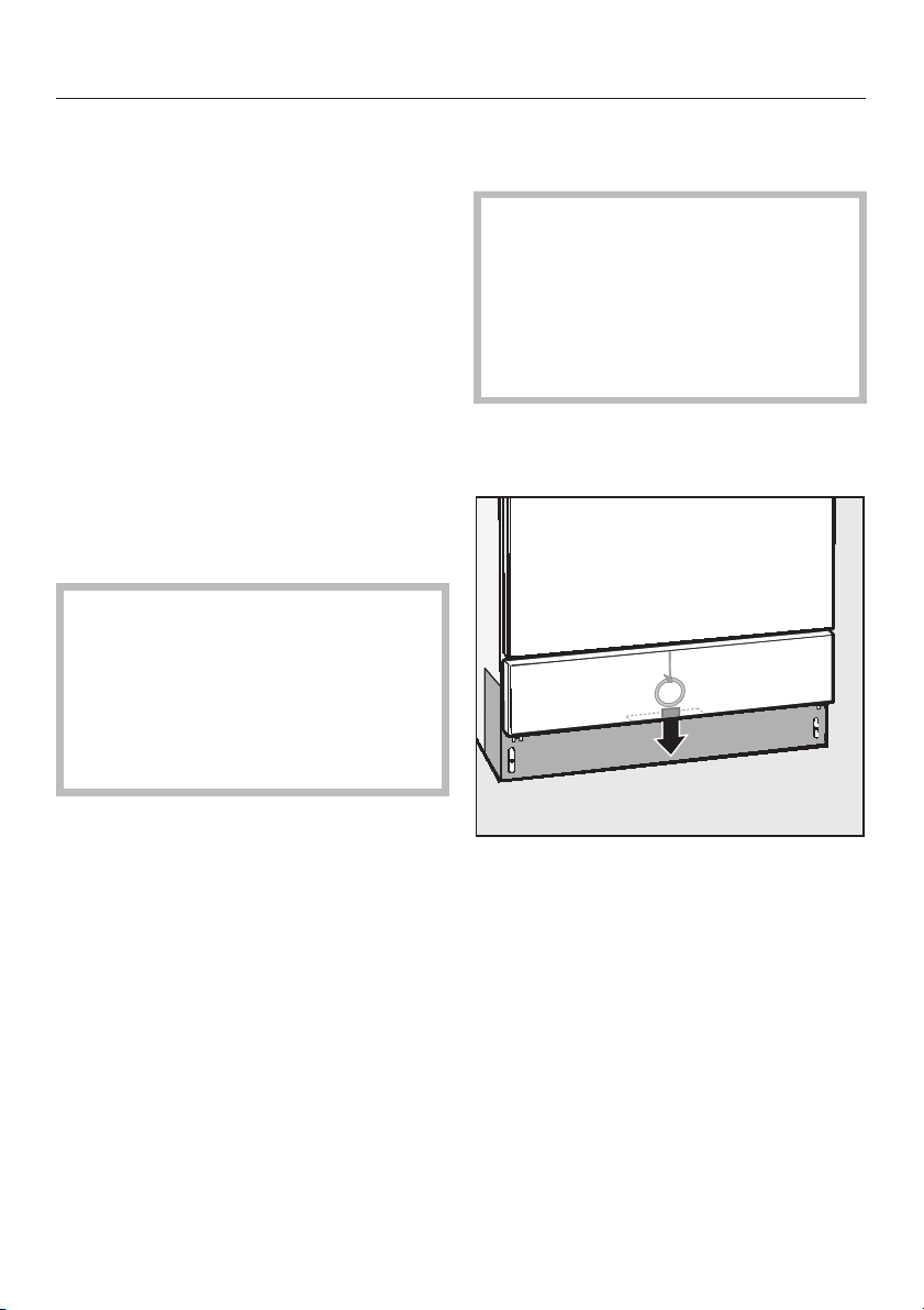
To open the door with the
emergency release
The emergency release should only
be used when the door cannot be
opened normally, e.g. in the event of
a power failure.
Important note for DESIN
programmes - read the notes in the
Warning and Safety instructions!
Switch the machine off with the I-0
^
button.
To close the door
^
Lift the door upwards and push until
it clicks shut.
14
^
The emergency release cable is
located at the bottom of the machine
behind the service panel. Pull it
downwards to open the door.
Page 15

Water softener
The water needs to be softened to
avoid calcium deposits building up on
instruments and utensils and in the
machine itself.
To ensure a steady supply of soft water,
the water softener unit must always be:
1. correctly programmed and
2. the salt reservoir must be filled.
If the water hardness level is below
4 °d - German scale (0.7 mmol/l), the
reservoir does not need to be filled
with reactivation salt.
The machine is set at the factory for a
water hardness level of 19 °d
(3.4 mmol/l).
If the water supply is harder or softer
than this (including below 0.7 mmol/l
or 4 °d) the factory setting will need
to be changed following the
instructions in "Setting the water
softener" in the Programming
Manual.
Your local water authority will be able to
advise you on the water hardness in
your area.
For future servicing it is useful to make
a note of your water hardness level.
Enter your water hardness level here:
^
°d (German scale)
or mmol/l
Setting the water softener
See "Operating information Reactivating the water softener" in the
Programming Manual supplied with the
machine.
Salt indicator
Reactivation salt will need to be
replenished when the NO SALT
indicator lights up in the display.
Reactivation takes place automatically
during a programme.
The programme sequence indication
light REACTIVATION lights up whilst this
is happening.
For fluctuating levels e.g. 8 - 17 °d
(1.4 - 3.1 mmol/l) set the water softener
to the highest setting. In this example to
17 °d (3.1 mmol/l).
The built-in water softener has
settings from 1 °d - 60 °d (0.2 -
10.8 mmol/l).
15
Page 16
Water softener
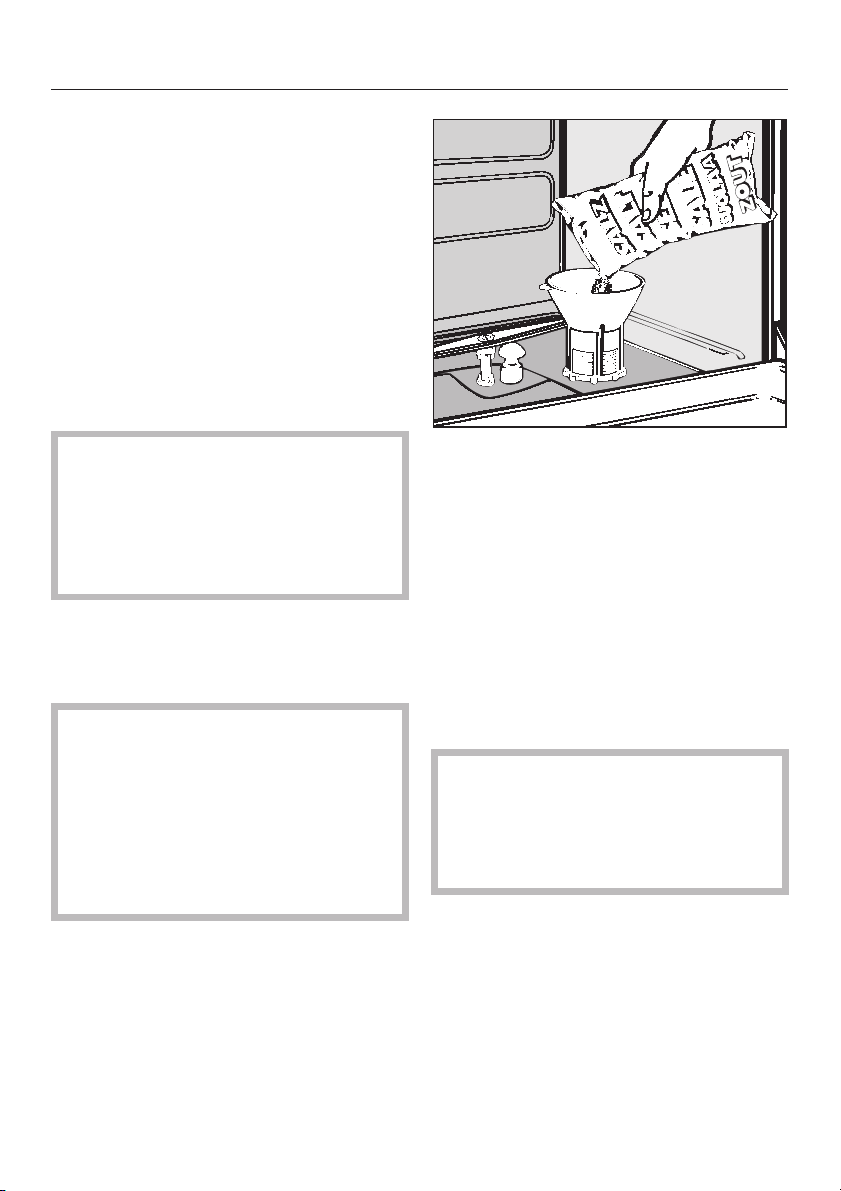
Filling the salt reservoir
Please only use special coarse grained
reactivation salt with granules of
approx. 1-4 mm. Do not use other types
of salt, e.g. table salt, agricultural or
gritting salt. These could contain
components which are insoluble in wa
ter which could result in damage to the
water softener. If in doubt consult the
Miele Professional Department.
The salt reservoir holds approx. 2.5 kg
of salt.
Inadvertently filling the salt
,
reservoir with cleaning agent will
damage the water softener.
Before filling the salt reservoir make
sure that you have picked up the
right packet of reactivation salt.
^ Remove the bottom basket from the
machine.
-
Place the funnel provided in place.
^
^ Fill carefully with salt.
As it is poured in, displaced water will
run out.
^ Wipe any residual salt off the screw
threads on the socket.
^ Screw the cap on firmly.
^ Unscrew the salt reservoir cap.
Important:
Before filling the salt reservoir with
dishwasher salt for the first time, you
must fill it with approx. 2.5 litres of
water to enable the salt to dissolve.
Once the dishwasher has been
used, there is always sufficient water
in the reservoir.
16
^ Select service programme REMOVE
SALT to flush out any traces of salt
from the cabinet.
If, after switching on the REMOVE
SALT programme, the start is
delayed for a few minutes this is not
a fault. The water softener is being
reactivated.
Page 17
Automatic mobile unit recognition (AWK)
In operating level C the (optional) AWK
allocates a fixed programme place to a
mobile unit with valid coding.
Programme places 1-15 are reserved
for the AWK automatic mobile unit
recognition.
The unit coding (on the mobile unit)
and the programme place with the
corresponding programme (in the
electronic control unit) have to match
each other.
To do this:
each mobile unit must be coded
^
before being used for the first time
(see "Coding the mobile unit"), and
^ the wash programme through which
the mobile unit is coded has to be
assigned to the relevant programme
place (operating level D, see the
"System function - Selector Switch
Organisation" section in the
Programming Manual).
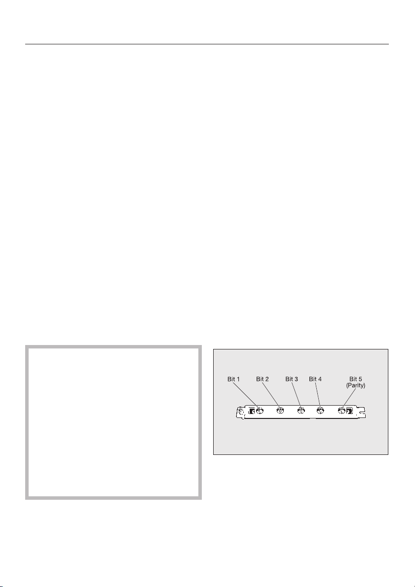
Mobile unit coding
The automatic mobile unit recognition
feature assigns a programme place to a
mobile unit. The mobile units must be
coded with a magnetic strip (via a Bit
combination).
In operating level C, the only
programme available for a coded
mobile unit is the one assigned to the
corresponding programme place.
After a coded mobile unit has been put
into the machine and the door closed,
the automatic mobile unit recognition
system will select the allocated
programme (as long as there are no
residues or particles on the magnetic
strip). Press 6 to start the programme.
Coding is effected through 5 Bits:
– Bits 1 to 4 define the mobile unit
code,
– Bit 5 serves as a control (Parity Bit).
Important
It is absolutely essential to check
that the programme required for the
mobile unit in use is the one shown
in the display before pressing the
Start button 6.
Otherwise inadequate cleaning or
disinfecting could be the result.
Please make sure that the places
assigned automatic mobile unit
recognition - AWK - are not changed
around arbitrarily.
17
Page 18

Automatic mobile unit recognition (AWK)
Mobile unit coding strip
15 different codes can be set. They are
assigned to programme places 1 to 15.
Under "System function, Selector switch
organisation" the matching
programmes have to be put into the
first 15 programme places.
Programme
place
1
2
3
4
5
6
7
8
9
10
11
12
13
14
15
Bit 1 Bit 2 Bit 3 Bit 4 Bit 5
0
-
0
0
I
I
0
I
I
0
0
0
I
I
0
I
I
0
0
0
I
I
0
I
I
0
0
0
I
I
0
I
I
Parity Bit
0
0
0
0
0
0
0
0
0
I
0
I
0
I
0
I
I
0
I
0
I
0
I
0
I
I
I
I
I
I
I
I
0
I
I
0
I
0
0
I
I
0
0
I
0
I
I
0
Setting mobile unit coding
To set or alter the coding of a mobile
unit with automatic recognition (AWK)
proceed as follows:
^ Unscrew the track with AWK (allen
key) and remove from the retainer.
The coded total must be an even
number.
If the coded total gives an odd number,
the message CHECK MOBILE UNIT
RECOGNITION appears.
If the mobile unit total equals 0, the
message NO MOBILE UNIT
RECOGNITION will appear. In neither
case can the programme be started
and the mobile unit recognition function
will have to be re-set.
18
^
Remove the magnetic strip from the
track.
Page 19

Automatic mobile unit recognition (AWK)
Set the programme place coding.
^
^
Put the magnetic strip back in the
track.
Important:
The magnetic strip must be placed in
the track so that the Bit coding set out
in the chart is visible through the round
windows in the track.
^ Place the track in the holder in the
mobile unit and screw firmly in place.
The magnetic strip on the G 7835
must have grey magnets.
19
Page 20

Areas of application
This washer-disinfector can be fitted
with a variety of mobile units,
depending on the type of items being
cleaned and disinfected. Various
baskets and inserts are also available
for a wide variety of instruments and
utensils.
The diversity of inserts and baskets
means that it is not possible to illustrate
them all or give detailed instructions on
their use here.
Before starting a programme you
should carry out a visual check on
the following:
– Is everything correctly
loaded/connected for cleaning?
– Are the spray arms clean and do
they rotate freely?
– Are the filters clean? Remove any
coarse soiling and clean them
properly if necessary.
– Is the adapter connecting the water
supply to the spray arms/jets
correctly connected?
Loading the machine
Removing excess soiling
Empty all containers before loading
^
into the machine (paying particular
attention to regulations regarding
epidemics).
Ensure that no acid or solvent
,
residues, especially hydrochloric
acid or chlorides, get into the wash
cabinet.
Preparing instruments for cleaning
^ This should preferably take place in a
dry state.
–
Are all chemical containers
sufficiently filled?
20
Page 21

Please note
Arrange the load so that water can
^
access all surfaces. This is to ensure
that it will be properly cleaned.
Do not place items to be cleaned
^
inside other pieces where they may
be concealed.
Hollow instruments must be
^
thoroughly cleaned, internally and
externally.
Hollow vessels should be inverted
^
and placed in the correct mobile
units, baskets and inserts to ensure
that water can flow in and out of them
unrestricted.
A cover net can be used to reduce
the risk of glass breakage during the
wash process.
^ Please check that instruments with
long narrow hollow sections can be
flushed through properly before
placing them in inserts or connecting
them to jets.
^
Lightweight items should be secured
with a cover net (e.g. an A 2) and
small items placed in a mesh tray to
prevent them blocking the spray
arms or being caught up with the
magnetic strip on the automatic
mobile unit recognition system.
Areas of application
Tall, narrow pieces should be placed
^
in the centre of the baskets. This
ensures good water coverage.
Mobile units and baskets with an
^
adapter must engage correctly.
The spray arms must not be blocked
^
by items which are too tall or which
hang down in their path. If necessary,
manually rotate the arms to test.
It is advisable to use only instruments
^
made of special application steel
which are not susceptible to
corrosion.
^ Instruments which cannot withstand
high temperatures should be
chemically disinfected.
^ Disposable instruments must not be
put into the machine for processing.
Select mobile units, baskets and
inserts which are appropriate for the
application.
Notes on the individual areas of
application and examples of loading
are given on the following pages.
^
Deep-sided items should be placed
at an angle to make sure water runs
off them freely.
21
Page 22

Areas of application
Water connection spring adapter
Make sure that the water connection
spring adapter engages correctly when
a basket or injector unit is inserted in
the machine. It must be 4-5 mm higher
than the water connection inlet in the
machine. If it is not:
Loosen the lock ring.
^
Push up the adapter and tighten up
^
the lock ring.
Height adjustable top basket
The top basket can be adjusted above
and below the middle position by 2 cm.
Depending on the position of the top
basket and the inserts used, the
baskets can accommodate vessels and
instruments of the following heights:
Example: Top basket O 190/1 and
bottom basket U 874
Top basket
position
Top max. 20 max. 24
Middle max. 22 max. 22
Bottom max. 24 max. 20
To adjust the top basket:
^ Pull out the top basket until a
resistance is felt; lift from the runners
and remove.
Top basket
height (cm)
Bottom
basket
height (cm)
22
^
Unscrew the roller bearings on both
sides of the basket with a suitable
spanner and reposition as required.
Page 23

Areas of application
Laboratory glassware (LG)
Wide-necked laboratory glassware,
e. g. beakers, wide-necked Erlenmeyer
flasks and Petri dishes, and cylindrical
shaped items e. g. test tubes, can be
cleaned and rinsed, internally and
externally, by the action of the rotating
spray arms. They can be arranged in
full, half and quarter inserts in an empty
bottom or top basket with spray arms.
Narrow-necked items e.g.
narrow-necked Erlenmeyer flasks,
conical flasks, measuring flasks and
pipettes, require mobile injector units or
injector modules.
The following instructions relate only to
basic preparation and loading of
glassware.
Loading the machine
Removing excess soiling
^ Empty all glassware before loading
into the machine (paying particular
attention to regulations regarding
epidemics).
Remove all stoppers, corks, labels,
^
sealing wax residues, etc.
Small parts - such as stoppers and
^
taps - should be secured in suitable
basket inserts.
Please note
Petri dishes and similar should be
^
placed in the correct insert with the
soiled side facing the centre.
Pipettes should be placed with the
^
mouthpiece facing upwards.
Quarter inserts should be placed in
^
the mobile unit with at least 3 cm
between them and the edge of the
mobile unit.
,
Ensure that no acid or solvent
residues, especially hydrochloric
acid or chlorides, get into the wash
cabinet.
^
Remove all agar residues from Petri
dishes.
^
Remove blood clots and residues
from test tubes, etc.
E 350 Mobile injector unit 1/1
(E 380 with connection for drying
unit TA)
For narrow necked laboratory
glassware with 32 (33) jets/clips.
23
Page 24

Areas of application
Surgical instruments (OP)
Surgical instruments should be stored
for as short a time as possible before
machine processing.
The OXIVARIO programme is
recommended for instruments where
there is a long delay between the time
they are used and the time they can be
reprocessed.
Disinfection of surgical instruments and
of those used for minimally invasive
surgery should preferably take place
thermally.
De-mineralised water should be used
for the final rinse when possible to
ensure no marks are left on the load
and to avoid corrosion. If the water
used contains more than 100 mg
chloride/litre there is danger of
corrosion.
E 327 Mobile unit/empty
For mesh trays on 2 levels
Open up hinged instruments and place
them in mesh trays so that they are not
touching each other.
When cleaning narrow lumen
instruments e.g. those used for
minimally invasive surgery, an
intensive internal cleaning result is
imperative. The Vario-TD and
OXIVARIO programmes are the only
ones which offer a thorough enough
level of cleaning for this. It is essential
that instruments are loaded as directed
and that the cleaning agent used is
suitable for the programme and for the
sensitive instruments being processed.
The final rinse must be carried out
using fully demineralised water with a
conductivity level of ~15 ZS/cm
(microsiemens per centimeter).
24
E 450 Mobile injector unit
for MIS instruments
(see separate Operating Instructions).
Page 25

Anaesthetic equipment (AN)
Anaesthetic instruments should be
thermally disinfected using the DESVAR-TD-AN programme.
If this is not possible they can be
processed using a chemo-thermal
programme. The water level in the
machine should be increased when
using a chemical disinfection
programme.
The standard of disinfection in
chemo-thermal disinfection
programmes depends on the
disinfection agent used.
Areas of application
E 435/3 AN Universal mobile unit TA
If the process is not to be followed
by sterilisation, the load should be
dried completely to avoid the
development of water-borne
bacteria.
A sufficient drying time is, therefore,
absolutely essential.
Breathing tubes must be carefully
connected and laid evenly up the
spiral.
for general AN instruments
(see separate Operating Instructions).
25
Page 26

Areas of application
Baby bottles (BC)
Baby bottles can be cleaned and
disinfected in one batch using 4 x
E 135 containers in top basket 0 190/1
and bottom basket U 874. Wide-necked
teats can be cleaned and disinfected in
an E 364, or screw cap teats in an
E 458 (top basket only).
Ensure the level marker on the bottles
^
is machine-washable.
After use, if there is a delay (e.g.
^
4 hours or more) before washing the
bottles, fill them with water to prevent
residues drying on before the bottles
are processed.
Loading
^ Empty the bottles before placing
them into the container.
^ Put the container lid in place over the
bottles and secure.
E 135 Insert 1/2
Container for 19 x 250 ml baby bottles
^ Place containers in the top and/or
bottom basket with the bottle necks
facing downwards, and unused
container corners to the outside.
Containers must be placed as close
to the middle of the unit as possible.
If the process is not to be followed
by sterilisation, the load should be
dried completely to avoid the
development of water-borne
bacteria.
A sufficient drying time is, therefore,
absolutely essential.
26
Page 27

Operating theatre shoes (OS)
Polyurethane operating theatre shoes,
and/or insoles should be cleaned and
chemo-thermally disinfected at 60 °C.
These can only be thermally disinfected
(using programme SHOE-TD-75/2) if
the manufacturer states that they are
made of a suitably heat-resistant
material.
To establish the effectiveness of
chemical disinfecting agents for
chemo-thermal disinfection, consult the
manufacturer.
Theatre shoes should be cleaned
and disinfected in a machine
installed specifically for this
purpose only.
Baskets O 167, O 173 and U 168/1 are
all suitable for this purpose.
Areas of application
Alternatively insert E 484 can be used
in a suitable bottom basket, e. g. U 874
together with holder E 487 for shoes or
E 489 for insoles.
A large amount of fluff can build up
in the machine when cleaning
theatre shoes. The filters in the wash
cabinet should therefore be checked
regularly, and cleaned when
necessary. See "Cleaning and care".
27
Page 28

Dispensing liquid chemical agents
Preparing the DOS dispensers
Only use agents formulated
,
specifically for use in
washer-disinfectors and make sure
you follow the manufacturer's
instructions.
This machine is fitted with 3 dispenser
pumps as standard:
Dispensing system DOS 1 (blue) to
–
dispense liquid cleaning agent. It
can dispense up to 120 ml/min.
Dispensing system DOS 2 (black) to
–
dispense H
dispense up to 120 ml/min.
– Dispensing system DOS 3 (red) to
dispense acid media such as
neutralising agent or rinsing agent. It
can dispense up to 20 ml/min.
Additional optional DOS modules:
– Dispensing system DOS 4 (green) to
dispense a low foaming disinfecting
agent, or for an additional cleaning
agent. It can dispense up to
120 ml/min.
The correct amount of liquid agent etc.
required for the application chosen will
then be dispensed through these
dispensing systems.
It is advisable to always keep 3
containers in the drawer, even if H
solution is not being dispensed. This
avoids the risk of the containers tipping
over when the drawer is opened or
closed.
solution. It can
2O2
2O2
The agents can be filled into 5 l plastic
containers, which are colour coded for
the relevant dispensing system.
When first commissioning, or when the
message FILL DOS 1 CONTAINER
and/or DOS 2, 3, 4 flashes in the
display after switching on or at the end
of a programme, fill the storage
container with the relevant agent.
If the message CHECK DISPENSING
SYSTEM 1 and/or CHECK DISPENSING
SYSTEM 4 flashes in the display, check
the storage containers, dispensing
tubes and pipes, and refill if empty. The
programme will stop automatically.
When first commissioning or when
the message CHECK DISPENSING
SYSTEM... appears, start the
DOS-FILL Programme to vent the
dispensing system (see "Venting the
Dispensing system").
,
Take great care when handling
liquid agents and additives. These
may contain irritant or corrosive
ingredients.
Please follow the manufacturer’s
safety instructions.
Wear protective gloves and goggles.
28
Page 29

Dispensing liquid chemical agents
Fill the containers with the relevant
agent
Switch the machine off.
^
^ Open the drawer on the control unit
to access the liquid agent containers.
^ Take the containers out, open them
and fill with the agent required, taking
care to observe the colour code.
DOS 4 (optional):
The DOS 4 dispensing system
container is not stored in the control
unit drawer. It should be placed next to
or on top of the washer-disinfector.
29
Page 30

Dispensing liquid chemical agents
Insert the tube into the reservoir
^
opening and screw on securely
(observe the colour code).
Once the storage containers have been
filled the relevant message goes out.
Refill the containers as soon as the
FILL CONTAINER DOS 1 and/or
DOS 2, 3, 4 message appears in the
display. Please remember to refill the
containers in good time. Do not let
them get empty.
Connecting the H
2O2
solution
container
The connection hose for the H
2O2
solution container is identified by a
black label. The connection hose is
supplied without a safety cap as the
container for hydrogen peroxide will
vary depending on supplier.
Connect the supplier's safety cap to
^
the connection hose (black).
Then connect this to the H
^
2O2
solution container.
Then start the DOS2-FILL programme.
Unlike with other liquid agents the
container for H
solution must be
2O2
allowed to empty completely before
it is changed over.
Wait until the FILL DOS 2
CONTAINER is displayed before
connecting a new H
2O2
solution
container and then start the DOS2
FILL programme.
If a container is not being used, the
level query for the unused
dispensing system can be turned off
to avoid the error message (see
"Machine functions, container
query..." in the Programming Manual
supplied with the
washer-disinfector).
30
If the CHECK DISPENSING SYSTEM
2 message appears you should check
the container as well as the dispensing
system. The programme will stop
automatically.
Page 31

Dispensing liquid chemical agents
Venting the dispensing system
Before the washer-disinfector is first
commissioned, and later on if one or
more containers has been allowed to
run dry, the dispensing system(s) for
liquid media will need to be vented. To
do this:
Press the I-0 button.
^
Select operating level B.
^
Select as required:
^
Programme DOS1-FILL
Programme DOS2-FILL
Programme DOS3-FILL
Programme DOS4-FILL.
(See "Operation/B. Free programme
selection).
^ Press the Start button 6.
The DOS-FILL Service Programmes
are allocated to programme places
58-61 ex works, but can be
re-allocated to other programme
places, if preferred.
Dispensing system
maintenance
To ensure trouble-free operation, the
following regular maintenance should
be carried out by a Miele approved
service technician.
Every 12-18 months
Replace the hoses in the dispensing
system(s).
External Dispensing systems
If external pumps are to be used for
dispensing liquid agents, please inform
the Miele Service Department. The
instructions given in the Programming
Manual under "Machine functions" will
need to be observed.
31
Page 32

Operation
There are four operating levels
available on this machine:
A = Fixed and free access
programmes
B = Free programme selection
C = AWK – Automatic mobile unit
recognition (programme selection
via mobile unit coding) - optional
D = Programming / free programme
selection / change code
(see Programming manual)
Switching on
^ Open the stopcocks (if turned off).
^ Press the I-0 button.
In operating levels A, B and D the most
recently selected PROGRAMME NAME
appears in the display and in operating
level C, AUTOMATIC MOBILE UNIT
RECOGNITION is displayed.
Changing the operating level
Press 1 and 2 at the same time.
^
Operating levels A B C D are shown
in the display.
Select the operating level you want
^
using the 1 or 2 buttons.
Press 6 to confirm selection.
^
Enter code when requested by the
^
display.
The code is set ex-works to ü0000<.
To enter the code:
– Press the start button 6,
[0000] will appear
– Enter numbers using the 4 and
3 buttons
– Select number position with the
1 or 2 button
– To confirm code press 6.
If you enter the wrong code:
FALSE CODE, PLEASE ENTER AGAIN
will appear in the display
32
^
Close the door.
Selecting or changing your own
code See "System functions" in the
Programming Manual:
Code 1 for levels ABC
Code 2 for levels ABCD
Page 33

Operation
Starting a programme
See the Programme charts in the
Programming Manual supplied with
the machine for detailed information
and important notes on the standard
Miele programmes.
A. Fixed programme
Set up fixed programme(s) once in
operating levels B or D and for free
access in operating level A (see
"System functions, Programmes under
A free access" in the Programming
Manual).
^ Select operating level A.
^ Check in the display that the
programme shown is the one
required.
If several fixed programmes have
been made freely accessible, select
the one required using the
programme selector.
^
Press the Start button 6.
B. Free programme selection
2. Programmes above place 24 are
selected using the 4 and 3 keys.
Turn the programme selector to 24.
^
Press 4 (scrolls forwards) until the
^
required programme is shown.
Press 3 (scrolls back) until the
^
required programme is shown.
3. The PROGRAMME SURVEY menu
lists all stored programmes. A
programme can be selected from this
menu.
To do this:
^ Select Programme Survey with 1
and confirm with 6.
^ Select a programme using 1 or 2.
^ Press 6 to confirm selection.
This exits the Programme Survey, and
the selected programme is shown in
the display.
After selecting one of the three options
above:
^
Press the Start button 6; the
programme proceeds.
^
Select operating level B.
In operating level B there are three
ways of selecting a programme.
1. Programme places 1 - 23 can be
selected using the Programme selector.
^
Turn the programme selector to the
required programme.
The programme name will appear in
the display.
For further information on programme
selection see "Operating Level B" in the
Programming Manual.
33
Page 34

Operation
C. AWK – Automatic mobile unit
recognition
Select operating level C.
^
Push the coded mobile unit into
^
place (see "Automatic mobile unit
recognition").
Close the door.
^
Important
It is absolutely essential to check
that the programme required for
this mobile unit is the one shown in
the display before pressing the Start
button to start the programme.
Otherwise inadequate cleaning or
disinfection could be the result.
Please make sure, that the places
assigned for the programmes using
AWK Automatic mobile unit
recognition are not changed around
arbitrarily.
^ Press the Start button 6.
Programme sequence
The programme will start automatically
as soon as the Start button has been
pressed. It is finished when
PROGRAMME END appears in the
display and the background lighting
flashes (press any button to switch off
the flashing lights).
See "System functions" in the
programming manual for further
information on switching off the flashing
signal.
Detailed information on programme
sequences is given in the appendix
of the Programming Manual.
The display background lighting
goes out automatically after approx.
15 mins. To bring it back on again,
press one of the buttons.
Switching off
If any changes have been made to
programmes or dispensing systems
these must be documented in a log
book kept with the machine in
accordance with the Medical Device
Directive (MPG directive 93/42/EWG,
Class IIa) and Health and Safety
Regulations.
Cleaning and disinfecting levels
must be revalidated after changing
parameters.
34
^
Press and release the I-0 button.
^
Turn off the stopcocks.
Page 35

Operation
To change or cancel a
programme
If the Start button has already been
pressed, a wrongly selected
programme can only be altered or
cancelled as follows:
If you interrupt the programme after
a disinfection stage has started you
cannot continue the programme.
1. In operating levels B or D
Press the Stop button 7. The
^
programme is interrupted.
>CANCEL< or >CONTINUE< will
appear in the display.
With established
,
decontamination programmes the
contaminated water must be
decontaminated before it is
discharged into the sewerage
system. The door can then be
opened.
2. In operating levels A or C
Select operating level B or D. See "To
^
change operating level".
You will be asked for your code.
In operating levels B or D proceed as
^
described under 1..
^
Use cursor 1 to select üCANCEL<;
the ü < cursor will start flashing.
^
Press the Start button 6. The
programme is cancelled and the wa
ter pumped away. DRAIN WATER
appears in the display.
^
After the water has been pumped
away the required programme can
be selected and started again.
-
35
Page 36

Operation
Interrupting a programme
If you absolutely have to open the door,
e.g. because the load is obviously
unstable (conscious intervention):
After interrupting a DESIN
disinfection programme, if you wish
to continue it please check the
message in the display at the end of
the programme. If the message
PROCESS PARAMETERS NOT MET
is displayed, it means the door was
opened after the disinfection part of
the programme and the DESIN
parameters were not fulfilled. If
necessary the programme must be
repeated.
1. In operating levels B or D
^ Press the Stop button 7. The
programme is interrupted.
>CANCEL< or >CONTINUE< will
appear in the display.
^ Open the door.
Rearrange the load. Follow infection
^
control regulations and wear
protective gloves.
Close the door carefully.
^
If a great deal of hot water is
,
present in the wash cabinet when
the programme is interrupted and
the door is then closed quickly, hot
water can escape.
Danger of burning or scalding.
Press the Start button 6 to continue
^
the programme.
2. In operating levels A or C
^ Press the I-0 button to interrupt the
programme.
^ Select operating level B or D. See "To
change operating level".
You will be asked for your code.
^ Press the I-0 button to continue.
^ Proceed as described under point 1.
,
Caution. Water and items in the
machine may be hot. Danger of
burning or scalding.
Where a chemical disinfection
programme has been used, be
aware that steam may contain high
quantites of disinfecting agent.
36
Page 37

Data transfer
There is a 9-pole sub-D socket on the
back of the machine for data transfer
between the Profitronic unit and an
external report printer or a PC.
The serial interface is RS 232
compatible.
Various printers can be used as
external printers:
Epson-compatible
–
(contact Miele for a list of suitable
models).
HP Laserjet
–
For the interface configurations see
"PC/Printer Function" in the
Programming manual.
Pin configuration in the 9-pole sub-D
connector at the back of the machine:
5 GND(base)
3 TXD (transmit)
2 RXD (receive)
1-4-6 (linked)
7-8 (linked)
Please note the following when
connecting a printer or PC:
– Only use an industry-standard PC or
printer (e.g. in Germany TÜV, or VDE
approved),
– the size of the printer or PC must be
taken into account when installing
the machine.
The report printer settings are
described in detail in the Programming
manual under "PC/Printer function".
A standard null-modem or laplink cable
can be connected.
The extension cable to the printer/PC
must not exceed 13 m.
37
Page 38

Cleaning and care
Cleaning the filters in the wash
cabinet
This machine must not be used
,
without all the filters in place.
The filter combination in the base of
the wash cabinet should be
inspected regularly and cleaned if
necessary.
Caution
,
Watch out for glass splinters which
could cause injury.
Cleaning the coarse filter
^ Press the two lugs together, remove
and clean the coarse filter.
^ Put the clean filter back in position
and press until it clicks in place.
38
Page 39

Cleaning the fine, flat and micro-fine
filters
Remove the coarse filter.
^
Remove the fine filter (if fitted) from
^
between the flat and the micro-fine
filters.
^ To unscrew the micro-fine filter, take
hold of the two lugs and turn twice in
an anti-clockwise direction.
Cleaning and care
Then remove together with the flat
^
filter.
^ Clean the filters.
^ Replace the filters by carrying out the
above steps in the reverse order.
Ensure that the flat filter sits flat in the
base of the wash cabinet.
39
Page 40

Cleaning and care
Cleaning the drain pump and
non-return valve
If water has not been pumped away at
the end of a programme the drain
pump or the non-return valve might be
blocked. They are however, easy to
clean.
Take the filter combination out of the
^
wash cabinet.
Release the locking clamp.
^
The drain pump is situated under the
non-return valve (see arrow).
^ Before replacing the non-return valve
check that the drain pump is free of
obstructions.
^ Carefully replace the ron-return valve
and secure with the locking clamp.
For safety reasons the load should
be cleaned and disinfected again.
^
Lift up the non-return valve and rinse
under running water.
40
Page 41

Cleaning and care
Cleaning the filters in the water
inlet
Filters are incorporated in the screw
connection of the water inlet hose to
protect the water inlet valve. If these
filters get dirty they need to be cleaned,
otherwise insufficient water flows into
the wash cabinet.
The plastic housing of the water
,
connection contains an electrical
component. It must not be dipped in
water.
To clean the filters
^ Disconnect the machine from the
mains electricity supply and
withdraw the plug from the socket
prior to cleaning the machine.
^ Turn off the stopcock and unscrew
the water inlet hose.
Reconnect the hose to the water inlet,
^
making sure that it goes back on
straight.
Open the stopcock carefully.
^
If there is a leak, screw the
connections on more tightly.
Cleaning the control panel
This should only be cleaned with a
^
damp cloth or a suitable cleaner for
use on plastic materials, or with a
disinfectant tested and recognised
as suitable for this use.
Do not use abrasive cleaners,
,
glass cleaners or all-purpose
cleaners!
Because of their chemical
composition they could cause
serious damage to plastic
components.
Cleaning the front of the
machine
^
Clean the large area filter (1) and fine
filter (2), and replace with new filters
if necessary.
^
Replace the filters and the seal. Make
sure they are sitting correctly.
^
Clean using a proprietary
non-abrasive cleaning agent
designed for use on stainless steel.
To help prevent marks e.g. from
fingerprints on the surface a
conditioning agent for stainless steel
may also be used. Follow the
manufacturer's instructions on the
packaging.
,
Do not use cleaning agents
containing ammonia or thinners as
these can damage the surface.
41
Page 42

Drying unit (TA) - Maintenance
Changing the coarse filter
The coarse filter should be changed
when the message CHANGE COARSE
FILTER flashes in the display.
Open the door to the control unit
^
cabinet.
^
^ Replace the perforated panel and
After the coarse filter has been
changed, reset the operating hours
^ Take out the perforated panel.
counter to zero, as follows:
^ Select the Programme CHANGE TA
Replace the coarse filter. The soft
side of the filter must face the front.
push it upwards to secure it.
COARSE (see Operation: B - Free
programme selection).
42
^
Press the Start button 6.
When the service programme has
ended, a message will appear in the
display.
^
To üCONTINUE< press 6.
Page 43

Drying unit (TA) - Maintenance
Exchanging the HEPA filter
The HEPA filter should be changed
when the message CHANGE FINE
FILTER flashes in the display.
This filter should only be
,
changed by a Miele Service
technician.
To ensure the machine operates
correctly, use original Miele HEPA
filters only (classification 13).
After the HEPA filter has been changed,
reset the operating hours counter to
zero, as follows:
^ Select the Programme CHANGE TA
FINE (see Operation: B - Free
programme selection).
^ Press the Start button 6.
When the service programme has
ended, a message will appear in the
display.
^
To üCONTINUE< press 6.
The CHANGE TA COARSE and
CHANGE TA FINE service
programmes have been allocated to
programme places 62 and 63
ex-works. If required, they can be
moved to other programme places.
See "System functions" in the
Programming manual.
43
Page 44

Installation
This machine should be connected
to the mains water supply in
accordance with local and national
water regulations. Please refer to the
installation diagram supplied with
the machine.
Furniture and fittings installed
,
near the machine must be of a
commercial standard able to
withstand the effects of steam and
condensation.
The machine must be installed correctly
and levelled.
Any unevenness in the floor level can
be compensated for and the height of
the machine raised or lowered by
adjusting the four screw feet.
When the feet are screwed in, the
machine can be moved backwards and
forwards on rollers.
The machine can be installed in the
following ways:
Free-standing. *)
–
Slot-in or at the end of a row: *)
–
The machine can be installed next to
other machines or furniture or in a
suitable niche. The niche must be at
least 90 cm wide and 70 cm deep.
*) A machine lid is essential with this
type of installation (available as a
special accessory).
The machine can be installed under
–
a continuous worktop or sink drainer.
Niche dimensions must be at least
90 cm wide, 70 cm deep and 82 cm
high.
Depending on the requirements for
building under, the following kits can be
ordered from the Miele Spares Dept.:
Cover plate (protects the worktop)
The underside of the worktop is
protected against steam rising from the
machine by a special cover plate.
44
Important for machines fitted with a
steam condenser (depending on
model):
To prevent damage by steam to the
worktop, the self adhesive protective
foil supplied (25 x 58 cm) must be
stuck in place underneath the worktop
near the steam condenser.
Page 45

Level and secure the machine
If fitted under a continuous worktop the
machine must first be aligned and then
screwed to the worktop.
Open the door. Secure the machine
^
to the front edge of the worktop using
screws through the holes on the left
and right hand sides of the front trim.
Installation
^ Do not use silicone sealant to seal
the gaps between the machine and
any neighbouring units as this would
hinder ventilation to the circulation
pump.
45
Page 46

Electrical connection
All electrical work must be
,
carried out by a suitably qualified
and competent person in
accordance with current local and
national safety regulations (BS7651
in the UK).
Connection should be made via a
–
suitable isolator, with an on-off switch
which is easily accessible for
servicing and maintenance work.
When switched off there must be an
–
all-pole contact gap of at least 3 mm
in the isolator switch.
– Equipotential bonding must be
carried out.
The machine must only be operated
with the voltage, frequency and fusing
shown on the data plate.
This machine can be converted in
accordance with the conversion
diagram and wiring diagram supplied.
The conversion diagram and data
plate with test certification (VDE, DVGW
etc.) are located on the rear of the
machine, and on the plinth (behind the
service panel).
The wiring diagram is secured to the
inner side of the service panel.
Bonding connection
– For extra safety it is advisable to
install a residual current device with
a trip current of 30 mA (in
accordance with DIN VDE 0664).
– The mains connection cable may
only be replaced by an original Miele
spare part or an appropriate cable
with wire end ferrules.
–
For technical data see data plate or
wiring diagram supplied.
There is a screw connection point
marked with the earth symbol (
the back of the machine, to which the
earth lead must be connected.
8) at
46
Page 47

Connection to the water inlet
The water in the machine must
,
not be used as drinking water.
The machine must be connected to
–
the water supply in accordance with
local and national water authority
regulations.
If the water supply has a high iron
–
content there is a danger of
corrosion occuring on items being
processed in the machine, as well as
in the machine itself.
If the chloride content of the water
exceeds 100mg/l the risk of
corrosion to items being processed
in the machine will be further
increased.
– This machine is constructed to
comply with German water
regulations (DVGW), and may be
connected to a suitable supply
without an extra non-return valve if
national regulations permit.
–
The water pressure (flow rate) must
be a minimum of 0.5 bar (50 kPa).
If the water pressure (flow rate) is
below 2 bar (200 kPa), the filling time
is automatically extended.
The max. permitted static pressure is
10 bar (1000 kPa).
If the water pressure is not in the
range of 0.5 to 10 bar (50-1000 kPa),
please contact the Miele Service
Department for advice. (The
message "CHECK WATER INLET" will
light up in the display)..
Plumbing
The machine is supplied as standard
–
for connection to a cold (coded blue)
and a hot (coded red) water supply
up to a max. temperature of 70 °C.
The inlet hoses should be connected
to the stopcocks for the hot and cold
water supplies. The steam
condenser inlet hose (without water
proof connector) should be
connected to the cold water
stopcock.
If a hot water supply is not available
the inlet hose coded red should also
be connected to the cold water
stopcock. AD-water connection
(marked H
– Stopcocks with 3/4 BSP male thread
are to be provided on site. They
should be easily accessible so that
the water supply can be turned off
when the machine is not in use.
– The DN 10 inlet hoses are approx.
1.7 m long terminating in a 3/4 inch
female thread. On no account must
the inlet filters be removed.
–
Large surface area filters are
enclosed in the kit supplied with the
machine for installing between the
stopcock and the inlet hose (see
illustration in Cleaning and Care 'Water inlet'). The large surface area
filter is made from chrome nickel
steel and can be recognised by the
matt top surface.
O pur) see next page.
2
-
47
Page 48

Plumbing
The inlet hoses must not be
,
shortened or damaged in any way
(see illustration).
See also the installation diagram
supplied.
AD water connection (pressurised)
ö 0.5 - 10 bar (50 - 1000 kPa) over
pressure
The machine is supplied as standard
for connection to an AD water supply of
0.5 - 10 bar (50 - 1000 kPa). If the water
pressure (flow rate) is below 2 bar (200
kPa) the water intake time is
automatically extended.
The AD pressure tested hose
^
(marked "H
threaded union must be connected to
the on-site AD stopcock for purified
water.
Note: If the machine is not going
,
to be connected to an AD water
supply, the cleaning and disinfecting
programmes will have to be altered
by a Miele Service technician.
The inlet hose will remain on the rear
of the machine.
O pur") with a 3/4"
2
48
AD water connection (without
pressure) 0.085 - 0.5 bar
(8.5 -50 kPa) Optional AD
The appliance must be converted
(special accessory) (if this has not
already been done at the factory)
before connecting to a water supply
0.085 - 0.5 bar (8.5 - 50 kPa). The feed
pump must be fitted by a Miele service
technician only.
When connecting an AD water
container (without pressure) the drain
connection must be at least the height
of the upper edge of the machine (see
"Installation instructions").
Page 49

Drainage
The drainage system is fitted with a
–
non-return valve which prevents dirty
water from flowing back into the
machine via the drain hose.
The machine should preferably be
–
connected to a separate drainage
system on site.
If separate drainage is not available
contact your Miele application
specialist for professional advice.
The on-site drain connection point
should be positioned between 0.3 m
and 1 m above the lower edge of the
machine.
If it is lower than 0.3 m, lay the hose
in a curve at a height of at least
0.3 m.
The drainage system must be able to
take a minimum drainage flow of
16 l/min.
Plumbing
– The inlet hose is approx. 1.5 m long,
is flexible and has an internal
diameter of 22 mm. It must not be
shortened.
Hose clips are supplied for securing
it in position.
–
A longer drain hose (up to 4 m long)
is available to order from the Miele
Spare Parts Dept.
–
The drainage system must not
exceed 4 metres.
See also the installation diagram
supplied.
49
Page 50

Technical data
Height: 85 (82) cm
Width: 90 cm
Depth: 70 cm
Voltage: see data plate
Connected load: see data plate
Fuse rating: see data plate
Mains connection cable: approx. 1.7 m
Water pressure (flow rate): 50 -1000 kPa (0.5 - 10 bar) pressure
Cold / hot water inlet connections: up to max. 70 °C
AD-water connection ü 50 - 1000 kPa (0.5 - 10 bar)
AD-water connection (non-pressurised) optional min. 8.5 kPa, max. 50 kPa
(0.085 - 0.5 bar)
Delivery head: min. 0.3 m, max. 1 m
Drainage length: max. 4 m
Inlet hose approx. 1.7 m
Drain hose: approx. 1.5 m
Steam condenser: approx. 2-4 l/min
Noise level in dB (A):
Sound level LpA Free standing: <70
Built under: <70
Test marks: VDE, interference suppression, DVGW,
! mark: MPG-Guidelines 93/42/EWG, Class IIa
50
Page 51

Problem solving
With the aid of the following explanatory
notes, minor faults can be corrected
without contacting the Miele Service
Dept.
Any work on the electrical components
of the machine should only be carried
out by a suitably qualified and
competent person in accordance with
local and national safety regulations.
Unauthorised repairs could be
dangerous.
Messages regarding the operating
status of the machine and fault
messages are shown in the display.
These are listed in charts in the
Programming Manual supplied
with the machine under
"Messages".
Thermal cut-out
This machine has a resettable heater
limiter which will shut off the heating
elements in the event of over-heating.
This could be caused, for example, by
large articles covering the heating
elements or if the filters in the wash
cabinet are blocked.
If the message "Check wash cabinet
heating" appears (water has not heated
up in the wash cabinet and the
programme is taking too long), proceed
as follows:
Remove the cause of the fault.
^
^ Take off the service panel (see
"Electrical connection").
^ Press the reset button on the heater
limiter (reddish brown) located on the
left-hand side of the plinth.
If this switch trips again contact the
Miele Service Department.
51
Page 52

After Sales Service
Should you have any difficulties please
contact your authorised Service Dealer
or the Miele Service Department.
See back cover for contact details.
–
When contacting your Service Dealer
^
or the Miele Service Office please
quote the model and serial number of
your machine.
This information can be found on the
data plate (see "Electrical connection").
Please note that telephone calls may
be monitored and recorded for
training purposes.
Technical safety
The Medical devices directive
93/42/EWG, which requires that safety
and operational checks are carried out
for all medical devices, has been
adopted into national law by all
European Union countries. Some
countries have added additional
regulations (e.g. MPBetreibV), which
require the operators themselves to
carry out these checks.
When EN ISO 15883 comes into force
internationally, users will be held
accountable for these checks.
In the U.K. safety checks to the
machine must be carried out every
3 months by a Miele approved service
technician in accordance with prEN
ISO 15883 and HTM 2030.
52
Page 53

Disposal of your old appliance or machine
Electrical and electronic appliances /
machines often contain materials
which, if handled or disposed of
incorrectly, could be potentially
hazardous to human health and to the
environment. They are, however,
essential for the correct functioning of
your appliance or machine. Please do
not therefore dispose of your old
machine or appliance with your
household waste.
Please dispose of it at your local
community waste collection / recycling
centre and ensure that it presents no
danger to children while being stored
for disposal.
It should be unplugged or disconnected
from the mains electricity supply by a
competent person. The plug must be
rendered useless and the cable cut off
directly behind it to prevent misuse.
See the "Warning and Safety" section of
this booklet for further details.
535455
Page 54

Page 55

Page 56

Alteration rights reserved / 3305
M.-Nr. 06 594 290 / 00
en-GB
 Loading...