


ALAN 8001S EURO


INDICE DEI CONTENUTI |
|
Installazione .................................................................................................................... |
2 |
Posizione ....................................................................................................................... |
2 |
Collegamenti ................................................................................................................ |
2 |
Interferenze sull’alimentazione ..................................................................................... |
2 |
Antenna ......................................................................................................................... |
2 |
Taratura antenna per R.O.S ottimale ........................................................................... |
3 |
Altoparlante esterno ..................................................................................................... |
4 |
Funzionamento ............................................................................................................... |
4 |
Comandi ed indicatori .................................................................................................. |
4 |
Pannello frontale .......................................................................................................... |
4 |
Pannello posteriore ...................................................................................................... |
6 |
Microfono P.T.T. ............................................................................................................ |
6 |
Procedura per ricevere ................................................................................................. |
6 |
Procedura per trasmettere ........................................................................................... |
7 |
Ricezione segnali SSB ................................................................................................. |
7 |
Roger Beep .................................................................................................................. |
8 |
Installazione di microfoni opzionali ............................................................................... |
8 |
Dati tecnici ...................................................................................................................... |
11 |
I TA L I A N O

I TA L I A N O
INSTALLAZIONE
POSIZIONE
Stabilire la posizione del ricetrasmettitore e della staffa del microfono prima di iniziare l’installazione. Scegliere una zona che sia congeniale ai fini del funzionamento e che non causi interferenze con l’autista od i passeggeri sul veicolo. Sulle automobili, solitamente il ricetrasmettitore viene montato sotto il cruscotto e con la staffa del microfono accanto a questo.
COLLEGAMENTI
Il ricetrasmettitore è dotato di una staffa di montaggio universale. Al momento dell’installazione in auto della staffa e della radio, assicurateVi che dal punto di vista meccanico la struttura sia resistente. Inoltre deve fornire un buon collegamento elettrico al telaio del veicolo. Per il montaggio procedere in base alle seguenti istruzioni:
1.Dopo aver stabilito la posizione più adatta sul veicolo, mantenere il ricetrasmettitore con la staffa di fissaggio nell’esatta posizione desiderata e verificare che non ci siano inconvenienti; successivamente segnare e forare il veicolo per il fissaggio dei bulloni di montaggio.
2.Collegare la presa del cavo dell’antenna a quella standard sul pannello posteriore. La maggior parte delle antenne per CB viene già dotata di connettori modello PL-259.
3.Collegare il filo rosso dell’alimentazione (con il fusibile) al positivo della batteria. Questo filo esce dal pannello posteriore. Per installazioni in auto, la tensione a 13.8 Vcc è solitamente prelevabile dal contatto ausiliario dell’interruttore d’accensione. Questo evita che l’apparato possa rimanere acceso accidentalmente quando l’autista scende dall’auto ed inoltre permette all’apparato stesso di poter lavorare senza che il motore sia in funzione.
4.Collegare il filo nero al negativo della batteria. Solitamente questo è il telaio dell’auto.
5.Montare la staffa del microfono utilizzando le due viti in dotazione. Per installazioni in auto posizionare la staffa sotto il cruscotto in modo che il microfono sia facilmente accessibile.
INTERFERENZE SULL’ALIMENTAZIONE
La presenza di rumori di tipo elettrico può normalmente influire sull’utilizzo di un ricetrasmettitore mobile quando i segnali ricevuti sono bassi. La principale causa dei rumori delle installazioni in auto sono da attribuirsi al generatore ed al sistema d’accensione del veicolo stesso. Nella maggior parte delle condizioni operative, quando il livello del segnale
è sufficiente, il rumore di fondo non rappresenta un problema grave.
In alcune installazioni l’interferenza sull’ alimentazione può essere così forte da rendere impossibile un buon livello di comunicazione. Questo rumore, di tipo elettrico, può derivare da diverse fonti; esistono molte possibilità ed in base alle caratteristiche diverse dei veicoli saranno necessarie soluzioni idonee per ridurre il rumore di fondo. Per risolvere questo problema Vi consigliamo di avvalerVi del Vostro elettrauto di fiducia.
ANTENNA
Potrete ottenere un funzionamento affidabile e la massima portata se lo stilo dell’antenna sarà polarizzato verticalmente ed a un quarto di lunghezza d’onda. Per applicazioni

dove non è necessario raggiungere la massima distanza, si trovano in commercio stili per antenne più corti, di tipo caricato, esteticamente validi e compatti adatti per altri tipi d’applicazione. Inoltre gli stili caricati non presentano il problema dell’altezza imposto da uno stilo ad un quarto di lunghezza d’onda.
Gli stili delle antenne di tipo mobile utilizzano la carrozzeria metallica del veicolo come contatto di massa. Nel caso vengano montati nell’angolo del veicolo, questi risultano leggermente direzionali, rispetto alla direzione della carrozzeria del veicolo. Per qualsiasi risultato pratico, tuttavia il tipo di radiazione è non direzionale. Solo per distanze estreme si terrà presente la lieve caratteristica direzionale.
TARATURA ANTENNA PER R.O.S. OTTIMALE
Poichè esiste un’ ampia gamma di antenne da base e mobili, questa sezione sarà strettamente collegata ai vari modelli di antenne mobili regolabili.
Siccome la lunghezza dell’antenna è inversamente proporzionale alla frequenza del canale, dovrà essere regolata per avere una risonanza ottimale su tutti i 40 canali, pertanto Vi suggeriamo di regolare l’antenna a centro banda.
Poichè esistono diversi modi per effettuare la taratura dell’antenna abbiamo scelto il metodo che a noi sembra il più congeniale possibile.
A.Antenna con viti di regolazione.
1.Svitare leggermente la vite di taratura in modo che sia facilmente regolabile usando le mani.
2.Posizionare il ricetrasmettitore sul canale 20. Premere il tasto del P.T.T. e regolare l’antenna (accorciandola). Il Rosmetro mostrerà un valore di lettura più basso ogni volta che l’antenna viene regolata. Continuando ad accorciare l’antenna noterete che il valore di lettura del R.O.S. si abbasserà e poi inizierà a salire nuovamente.
Questo significa che avete superato il livello ottimale per il canale 20. Regolare l’antenna ripetendo le istruzioni sopra riportate.
B.Antenne da tagliarsi ad una lunghezza appropriata.
1.Seguire la stessa procedura come sopra indicato, ma regolare la lunghezza tagliando
2/3 mm alla volta finchè non si otterrà una buona regolazione.
2.Fate attenzione a non tagliare troppo in una volta sola, poichè quando è tagliata non la si potrà più allungare.
3.Si potrà facilmente tagliare lo stilo intaccandolo con una lima e staccando la parte segnata con le pinze.
In caso abbiate qualche problema per la taratura della Vostra antenna, controllare i punti seguenti:
A.Durante la fase di taratura tutte le portiere devono essere chiuse.
B.AssicurateVi che la base dell’antenna sia a massa.
C.Controllare il cablaggio del cavo coassiale che non venga schiacciato.
D.Variare la posizione rispetto alla Vostra auto (tenendo presente la caratteristica di radiazione che desiderate)
E.L’antenna è in posizione perfettamente verticale?
F.Mantenere una certa distanza da oggetti di metallo di grandi dimensioni durante la fase di regolazione.
N.B: Questo ricetrasmettitore opererà con un valore di R.O.S. pari da 2 a 1 a tempo indeterminato e potrà sostenere un R.O.S. di 20:1 per un tempo massimo di 5 minuti in condizioni operative nominali.
I TA L I A N O
I TA L I A N O
ALTOPARLANTE ESTERNO
Lapresadell’altoparlanteesterno(EXT.SPK.)sulpannelloretrostantevieneutilizzatacome controllo a distanza del ricevitore. L’altoparlante esterno deve avere 8 ohm d’impedenza e deve poter sopportare almeno 4 watt. Quando l’altoparlante esterno è inserito, quello interno risulta scollegato.
FUNZIONAMENTO
COMANDI E INDICATORI
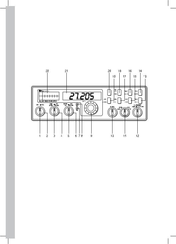
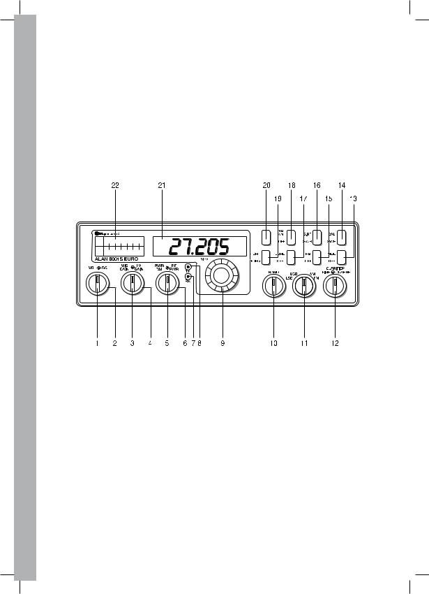
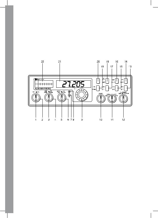
Sul pannello frontale del Vostro ricetrasmettitore si trovano 18 comandi e 4 indicatori.
PANNELLO FRONTALE
1.VOLUME ON/OFF (interno). Girare in senso orario per determinare il livello d’ascolto desiderato. Durante il normale funzionamento CB, il comando del VOLUME viene utilizzato per regolare il livello d’uscita sia dell’altoparlante del trasmettitore che di quello esterno.
2.SQUELCH (esterno). Questo comando viene utilizzato per eliminare il rumore di fondo del ricevitore in assenza di segnali d’ingresso. Per la massima sensibilità del ricevitore
èpreferibile che il comando sia regolato solo al preciso livello dove il rumore di fondo del ricevitore o il rumore di fondo ambientale viene eliminato. Girare completamente in senso antiorario poi lentamente in senso orario finchè non scomparirà il rumore del ricevitore. Qualsiasi segnale, affinchè possa venir ricevuto, dovrà essere leggermente più intenso rispetto alla media del rumore ricevuto. Un’ ulteriore rotazione in senso orario aumenterà il livello di soglia che il segnale dovrà superare per poter essere udito. Se lo squelch sarà posizionato nella massima posizione in senso orario si potranno sentire solo segnali molto forti.
3.GUADAGNO MICROFONO (interno). Regola il guadagno microfonico in trasmissione.
4.CONTROLLO GUADAGNO RF (esterno). Da utilizzarsi per ridurre il guadagno del- l’amplificatore RF in presenza di forti segnali.
5.COMANDO R.O.S. CAL (interno). Per poter ottenere la massima potenza radiante

e la massima portata, è importante che l’antenna sia in buone condizioni e correttamente tarata. Il Rosmetro incorporato Vi permette di misurare facilmente le condizioni operative dell’antenna. Per rendere attiva questa funzione, collegare l’antenna al connettore d’uscita. Selezionare un canale nella banda centrale come il 21 o il canale che utilizzate più frequentemente. Regolare il commutatore 16 sulla posizione SWR, mentre il commutatore 14 sulla posizione SWR CAL. Tenere premuto il tasto del P.T.T. del microfono e mediante il comando SWR CAL, regolare l’indice dello strumento sulla posizione CAL. Successivamente, mantenendo sempre il tasto del P.T.T. premuto, regolare il commutatore 14 sulla posizione OFF e leggere il valore indicato. Il numero
1 sarebbe il valore ideale. Generalmente, i valori fino a 3 sono accettabili, ma oltre il 3 significa che state perdendo potenza radiante e potrebbe rendersi necessaria una regolazione dell’antenna.
6.COMANDO DI POTENZA RF (esterno). Questo comando Vi permette di regolare la potenza d’uscita RF da 1 watt a 4 watt (SSB).
7.INDICATORE DI RICEZIONE. Tale indicatore sarà illuminato quando l’apparato è in ricezione.
8.INDICATORE DI TRASMISSIONE. Tale indicatore sarà illuminato quando l’apparato è in trasmissione.
9.SELETTORE CANALI. Questo commutatore seleziona uno dei 40 canali nella banda
CB. Il canale selezionato viene visualizzato direttamente sul display a LED sopra la manopola per la selezione dei canali.
10.SELETTORE DI BANDA. Comando che permette di spostarsi di 10 canali per volta.
11.COMMUTATORE DI FUNZIONE. Questo commutatore viene impiegato per selezionare il tipo di funzionamento LSB, USB, AM, FM. Normalmente si opera in AM o FM, a meno che la stazione con la quale volete comunicare disponga della funzione SSB. Il commutatore di funzione cambia simultaneamente la funzione sia del trasmettitore che del ricevitore.
12.CLARIFIER. Questo comando Vi permette di variare le frequenze operative del ricevitore sopra e sotto la frequenza assegnata. Sebbene questo comando sia ritenuto fondamentale per sintonizzare i segnali in SSB, può essere utilizzato per migliorare i segnali AM/FM come è stato descritto nei paragrafi relativi al funzionamento.
13.COMMUTATORE MOD/OFF. In posizione MOD, lo strumento indicherà la percentuale di modulazione, mentre in OFF la potenza RF in uscita.
14.COMMUTATORE SWR CAL/OFF. Tale comando in posizione SWR/CAL serve per effettuare la calibrazione del rosmetro.
15.INTERRUTTORE ROGER BEEP. Quando questo interruttore è nella posizione ROGER BEEP, la Vostra radio trasmetterà automaticamente il segnale audio di fine trasmissione. L’interlocutore può facilmente stabilire che la trasmissione è terminata attraverso questo particolare segnale.
16.COMMUTATORE S-RF/SWR. Quando è in posizione SRF, lo strumento in ricezione indica l’intensità del segnale ricevuto e durante la trasmissione mostra la potenza d’uscita. In posizione SWR permette di misurare il rapporto di onde stazionarie dopo aver eseguito la calibrazione.
17.INTERRUTTORE ECO (OPZIONALE). Questo interruttore è da utilizzarsi quando si
vuole aggiungere l’effetto ECO in trasmissione. Questo interruttore non può agire in ricezione.
18.INTERRUTTORE NB/ANL-OFF. In posizione NB/ANL si attiva il controllo automatico di disturbi e agisce come filtro; in posizione OFF si disattiva.
19.INTERRUTTORE FREQ-CHANNEL. In posizione FREQ tale comando attiva il frequenzimetro; in posizione CHANNEL, le due cifre indicano il canale selezionato.
20.NON UTILIZZATA.
I TA L I A N O
O |
21. DISPLAY FREQUENZIMETRO. Indica la frequenza su cui si sta operando e il canale |
|
N |
selezionato. |
|
I A |
||
22. INDICATORE. Questo strumento indica l’intensità dei segnali in ricezione, il livello di |
||
AL |
||
R.O.S., la potenza d’uscita RF del trasmettitore, la percentuale di modulazione in tra- |
||
I T |
smissione e permette la calibrazione del Rosmetro. |
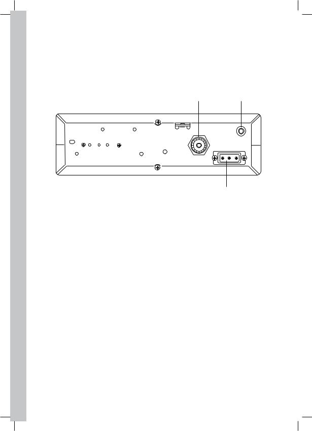
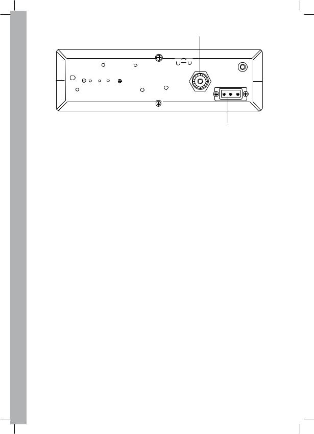
PANNELLO POSTERIORE
25 24
ANT
EXT.SP.
- POWER+
23
23.ALIMENTAZIONE. Accetta un cavo d’alimentazione da 13.8 Vcc con il fusibile incorporato.
24.ALTOPARLANTE ESTERNO. Accetta altoparlanti con potenza di 5 watt ed impedenza da 4 a 8 ohm.
25.ANTENNA. È compatibile con connettore PL-259.
MICROFONO P.T.T.
Il ricevitore e il trasmettitore sono controllati dall’interruttore del P.T.T. del microfono. Premendo questo interruttore verrà attivato il trasmettitore, rilasciandolo si passa in ricezione. Durante la trasmissione, tenere il microfono ad una distanza di circa 10 cm dalla bocca e parlare con un tono di voce normale. Gli apparati vengono forniti con un microfono dinamico a bassa impedenza (500 Ohm).
PER RICEVERE
1.Prima di procedere assicurateVi che l’alimentazione, il microfono e l’antenna siano collegati ai connettori esatti.
2.Accendere l’apparato girando il comando VOL in senso orario.
3.Stabilire un livello d’ascolto, regolando il volume.
4.Posizionare il commutatore MODE (11) sulla funzione desiderata.
5.Ascoltare il rumore di fondo dall’altoparlante. Girare il comando SQUELCH lentamente in senso orario finchè non scomparirà (non deve essere presente nessun segnale). Mantenere il comando in questa posizione. Lo SQUELCH è ora correttamente regolato. Il ricevitore dovrebbe rimanere silenziato finchè non si sentirà un segnale. Non portare il comando troppo avanti in quanto potrebbero non sentirsi i segnali più deboli.

6. Posizionare il commutatore per la selezione dei CANALI sul canale desiderato. |
O |
|
7. Regolare il comando di guadagno RF completamente in senso orario per ottenere il |
N |
|
I A |
||
massimo guadagno RF. |
||
AL |
||
8. Regolare il CLARIFIER per rendere più chiari i segnali SSB o per ottimizzare quelli |
||
AM/FM. |
I T |
PER TRASMETTERE
1.Selezionare il canale desiderato sul quale si vuole trasmettere.
2.Regolare il comando del GUADAGNO del MICROFONO completamente in senso orario.
3.Se il canale è libero, premere il tasto del P.T.T e parlare con un tono di voce normale.
RICEZIONE SEGNALI SSB
Esistono 4 tipi di segnali normalmente usati nella banda CB: FM, AM, USB e LSB. Quando l’interruttore MODE si trova in posizione AM, (doppia banda laterale) o in posizione FM, (deviazione di frequenza), si sentiranno i soli segnali a portante completa. Un segnale
SSB può essere riconosciuto sia in AM che FM grazie al suo suono tipico ‘’Donald Duck
(Paperino)’’ e all’impossibilità del ricevitore di riprodurre un’uscita comprensibile. Le funzioni USB e LSB riveleranno rispettivamente bande laterali superiori ed inferiori, e inoltre segnali standard AM.
La ricezione SSB differisce da quella AM nel fatto che il ricevitore SSB non richiede una portante od una banda laterale opposta per poter riprodurre un segnale comprensibile. Un segnale trasmesso da una banda laterale singola consiste solo nella banda laterale superiore o inferiore e non viene trasmessa nessuna portante. L’eliminazione della portante dal segnale AM aiuta ad eliminare fischi e toni sul canale, i quali rendono intelligibili, a volte, anche segnali AM medio/forti; inoltre, l’SSB occupa solo un mezzo canale AM, perciò le 2 conversazioni SSB s’inseriranno in ogni canale, espandendo i 40 canali AM ai 80 SSB.
La riduzione nello spazio dei canali, inoltre aiuta il ricevitore, perchè solo metà del rumore e dell’interferenza può essere ricevuta con il 100% del segnale SSB.
È possibile ricevere un segnale SSB solo quando il ricevitore d’ascolto opera sulla stessa sintonia. In altre parole, è possibile comprendere un segnale in banda laterale superiore
(USB) solo se il ricevitore opera in posizione USB.
Se si sente un segnale in banda laterale inferiore (LSB) quando il ricevitore è regolato nella funzione USB, non sarà possibile rendere il segnale comprensibile. È possibile comprendere la ragione di tutto questo se considerate che quando la modulazione viene applicata al microfono del trasmettitore nella funzione USB, la potenza d’uscita del trasmettitore aumenta, mentre nella funzione LSB la frequenza d’uscita del trasmettitore diminuisce.
Quando ascoltate un segnale in AM, sentirete correttamente entrambe le funzioni USB ed
LSB in quanto si riceve sia la banda laterale superiore che inferiore.
Non appena viene selezionata la funzione SSB, potrebbe rendersi necessaria una regolazionealfinedirenderecomprensibileilsegnaleinentrata;ilcomandodelCLARIFIER permette all’operatore di variare la frequenza sopra e sotto l’esatta frequenza centrale del segnale in ricezione. Se il suono del segnale in ingresso è di tono alto o basso, regolare il funzionamento del CLARIFIER. Il tutto è paragonabile ad un giradischi con regolazione della velocità: a velocità più bassa del normale i toni saranno più gravi, a velocità più elevata i toni saranno più acuti. Esiste solo una velocità corretta in grado di produrre una
I TA L I A N O
riproduzione uguale al suono registrato. Se si ascolta la registrazione con un giradischi che ruota nella direzione sbagliata (banda laterale opposta), sarà impossibile ottenere un suono comprensibile anche con un controllo della velocità (CLARIFIER).
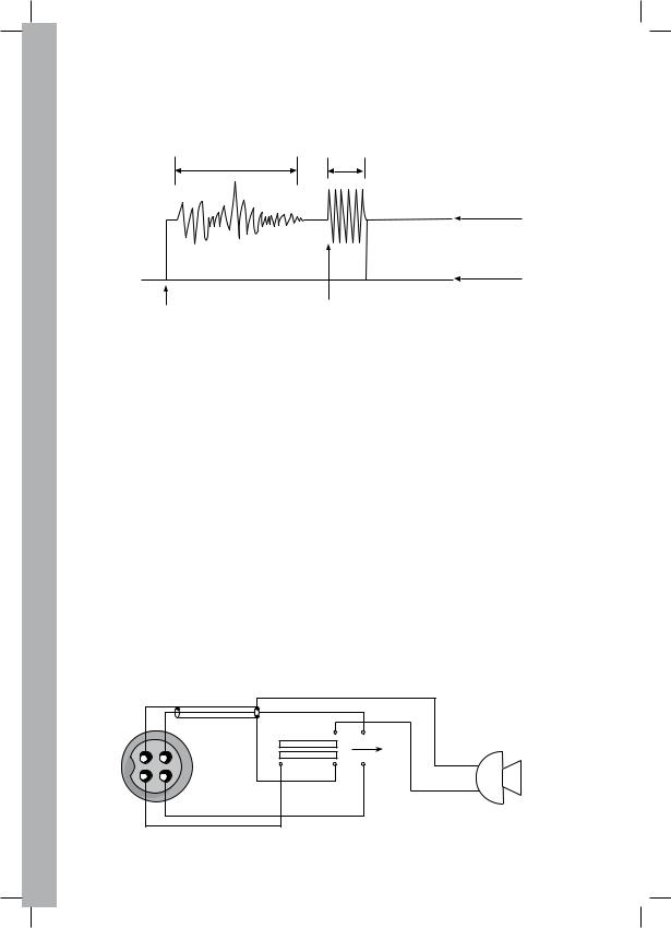
ROGER BEEP
In condizioni normali, il Vostro apparato trasmetterà automaticamente il segnale audio di fine trasmissione. L’utente può facilmente capire che la trasmissione è terminata grazie a questo segnale. Questo ROGER BEEP trasmetterà per 0,15 secondi dal momento che l’interruttore del P.T.T. è rilasciato.
VOCE BEEP
O.15 Sec
TX
RX
P.T.T. ATTIVO |
P.T.T. RILASCIATO |
|
FIG. 1 |
INSTALLAZIONE DI MICROFONI OPZIONALI
Per ottenere le migliori prestazioni, l’utente dovrebbe scegliere un tipo di microfono dinamico a bassa impedenza, o un microfono preamplificato. I microfoni preamplificati sono caratterizzati da una bassa impedenza d’uscita. Questi microfoni devono essere provvisti di un cavo a 4 fili.
Il microfono dovrebbe svolgere le funzioni riportate nello schema seguente:
CAVO MICROFONO A 4 FILI
Numero Pin Filo del cavo del microfono
1Schermo audio
2Conduttore audio
3Controllo trasmettitore
4Controllo ricevitore
1 |
2 |
TX |
4 |
3 |
MIC |
|
FIG. 2. Schema del microfono del ricetrasmettitore
Se il microfono è provvisto di fili pretagliati, questi devono essere predisposti come segue:
1.Tagliare i fili in modo che sporgano circa 12 mm oltre il rivestimento in plastica isolante del cavo del microfono.
2.Tutti i fili dovrebbero essere tagliati alla stessa lunghezza. Spellare l’estremità di ogni
filo fino ad una lunghezza di 3 mm e successivamente stagnarli.
Prima di procedere con questo tipo di cablaggio, leggere attentamente le istruzioni relative al circuito del microfono. Per saldare i vari collegamenti utilizzate un saldatore piccolo.
Mantenere al minimo le lunghezze dei fili scoperti per evitare il cortocircuito quando verrà riassemblata la presa del microfono.
|
|
ANELLO |
|
CONTATTI |
|
DENTELLATO |
TELAIO |
|
|
||
4 3 |
|
|
|
1 2 |
|
|
|
|
CONTATTIERA |
|
SERRACAVO |
|
|
|
|
|
|
VITE DI |
|
|
|
FISSAGGIO |
|
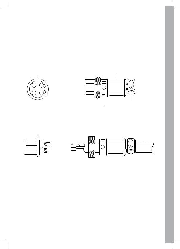
A. ASSEMBLAGGIO DEL CONNETTORE MICROFONO
RONDELLA
B. CONNETTORE DEL MICROFONO, SMONTATO PER IL CABLAGGIO
FIG. 3. Collegamento presa microfono
1.Togliere la vite di fissaggio.
2.Svitare il telaio dal supporto dei pin.
3.Allentare le due viti di fissaggio del morsetto del cavo.
4.Infilare il cavo del microfono attraverso la carcassa, l’anello dentellato e la rondella come mostra la Fig. 3.
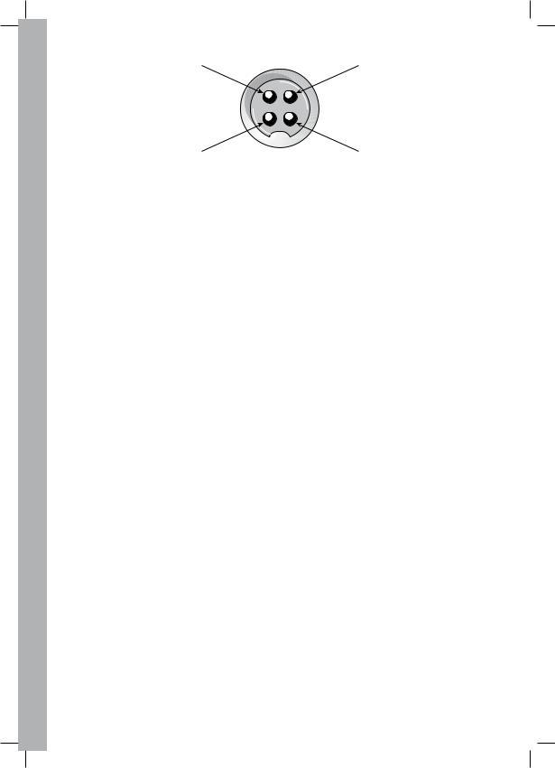
5.I fili dovranno essere saldati ai pin come indicato nello schema sopra riportato. La figura
4 mostra il numero dei pin della presa del microfono, visti dalla parte inferiore di tale presa. Prima di saldare i fili ai pin, prestagnare ogni singolo pin della presa. AssicurateVi che il telaio e l’anello dentellato della Fig. 3 vengano rienseriti nel cavo del microfono prima di iniziare la saldatura. Se verrà utilizzata la presa del microfono come supporto durante le fasi di saldatura, converrà saldare i pin nel seguente ordine 1 , 3, 2, 4 e limitare al minimo il tempo di saldatura e la quantità di stagno usata.
I TA L I A N O

I TA L I A N O
3 |
2 |
4 |
1 |
FIG. 4. Numero di pin della presa del microfono. Vista posteriore
6.Una volta completate tutte le saldature, inserire direttamente l’anello dentellato e il telaio sulla parte filettata della presa. Fate attenzione alla posizione del foro per la vite. Quando il telaio è completamente inserito nel supporto, potrebbe rendersi necessario girarlo, sia in senso orario che in senso antiorario, al fine di allineare il foro della vite nella filettatura alla presa. Una volta sistemate queste, la vite di fissaggio verrà riavvitata per fissare maggiormente il telaio alla presa.
7.Le 2 viti di fissaggio del cavo devono essere ben serrate per assicurare un buon contatto meccanico tra cavo e presa. Se avete seguito attentamente le istruzioni relative ai collegamenti, il bloccaggio dovrebbe stringere il rivestimento isolante del cavo del microfono.
8.Dopo aver completato il cablaggio della presa, collegare la presa del microfono al trasmettitore.
10

DATI TECNICI
Generali
Canali |
40 CH/AM/FM/USB/LSB |
Gamma di frequenza |
26.965 - 27.405 MHz |
Controllo frequenza |
Sintetizzatore PLL |
Tolleranza di frequenza |
0,005% |
Stabilità di frequenza |
0,001% |
Gamma temperatura |
da -10°C a + 55°C |
Microfono |
Dinamico con P.T.T. con cavo spiralato e |
|
connettore 4 poli |
Tensione d’alimentazione |
13,8 Vcc nominali ± 10% |
Assorbimento |
Trasmettitore: FM, 4A - Uscita SSB PEP, 6A |
|
Ricevitore: Squelch, 0,6A - Massima uscita audio, 1,2A |
Dimensioni |
6 cm (A) x 20 cm (L) x 23,5 cm (P) |
Peso |
2,250 Kg |
Connettore antenna |
UHF, SO239 |
Strumento (3 in 1) |
Illuminato; indica la potenza d’uscita relativa; |
|
intensità segnali d’entrata, R.O.S. |
Ciclo di utilizzo |
5/5/90 |
Trasmettitore |
|
Potenza d’uscita |
SSB: 4W - FM: 4W - AM: 1W |
Modulazione |
AM/FM/SSB |
Soppressione portante SSB |
55 dB |
Banda laterale indesiderata |
50 dB |
Risposta frequenza |
AM e FM: da 300 a 3000 Hz |
Impedenza d’uscita |
50 ohm, sbilanciati |
Indicatori d’uscita |
L’indicatore mostra la potenza d’uscita RF relativa. Il LED |
|
rosso di trasmissione si illumina quando il trasmettitore è |
|
in funzione. |
Ricevitore |
|
Sensibilità |
SSB: 0,25µV per 10 dB (S+N)/N; |
|
AM: 0,6 µV per 20 dB (S+N)/N; |
|
FM: 0,6 µV per 20 dB (S+N)/N |
Frequenza IF |
AM/FM: 10.695 MHz 1° IF, 455 KHz 2° IF |
|
SSB: 10.695 MHz |
Reiezione canale adiacente |
60 dB AM/FM e 70 dB SSB |
Controllo guadagno RF |
45 dB regolabile per ottimizzare la ricezione del segnale |
Controllo guadagno automatico |
Variazioni d’uscita audio inferiori a 10 dB con ingresso da |
|
10 a 100,000 µV |
Squelch |
Regolabile; soglia meno di 0,5 µV |
ANL |
Automatico |
Gamma di frequenza del Clarifier |
Coarse (RX) ± 5 KHz Fine (RX) ± 1 KHz |
Potenza d’uscita audio |
4 watt su 8 ohm |
Risposta frequenza |
300 ÷ 3KHz |
Altoparlante incorporato |
8 ohm, circolare |
Altoparlante esterno (opz.) |
8 ohm, disattiva quello interno quando è collegato |
I TA L I A N O
11


TABLE OF CONTENTS |
|
Installation......................................................................................................................... |
2 |
Location......................................................................................................................... |
2 |
Mounting the Connection ............................................................................................. |
2 |
Ignition Noise Interference............................................................................................. |
2 |
Antenna ........................................................................................................................ |
2 |
Tuning the Antenna for Optimum SWR ........................................................................ |
3 |
External Speaker .......................................................................................................... |
4 |
Operation ......................................................................................................................... |
4 |
Controls and Indicators ................................................................................................ |
4 |
Front Panel..................................................................................................................... |
4 |
Real Panel...................................................................................................................... |
6 |
P.T.T. Microphone ......................................................................................................... |
6 |
Operating Procedure to Receive .................................................................................. |
6 |
Operating Procedure to Transmit ................................................................................. |
6 |
Receiving SSB signals................................................................................................... |
7 |
Roger Beep .................................................................................................................. |
8 |
Alternate Microphones and Installation ........................................................................ |
8 |
Specifications.................................................................................................................. |
11 |
E N G L I S H

E N G L I S H
INSTALLATION
LOCATION
Plan the location of the transceiver and microphone bracket before starting the installation. Select a location that is convenient for operation and does not interfere with the driver or passengers inside the vehicle. In cars, the transceiver is usually mounted below the dash panel, with the microphone bracket beside it.
MOUNTING THE CONNECTION
The transceiver is supplied with a universal mounting bracket. When mounting the bracket and radio inside your car, make sure it is mechanically strong. Also provide a good electrical connection to the chassis of the vehicle. To mount the transceiver, proceed as follows:
1.After you have determined the most convenient location in your vehicle, hold the transceiver with mounting bracket in the exact location you have chosen. If nothing interferes with mounting it in the desired position, remove the mounting bolts. Before drilling the holes, make sure nothing will interfere with the installation of the mounting bolts.
2.Connect the antenna cable plug to the standard receptacle on the rear panel. Most CB antennas are terminated with a PL 259 type plug and mate with the receptacle.
3.Connect the red DC power input wire (with the fuse) to +13.8 Vdc. This wire extends from the rear panel. In automobile installation, +13.8 Vdc is usually obtained from the accessory contact on the ignition switch. This prevents the set being left on accidentally when the driver leaves the car, and also permits operating the unit without the engine running. Locate the accessory contact on most ignition switches by tracing the power wire from the AM broadcast receiver in the car.
4.Connect the black lead to +13.8 Vdc. This is usually the chassis of the car. Any convenient location with good electrical contact (remove paint) may be used.
5.Mount the microphone bracket on the right side of the transceiver or near the transceiver, using the two supplied screws. When mounting on a car, place the bracket under the dash so the microphone is readily accessible.
IGNITION NOISE INTERFERENCE
The use of a mobile receiver at low signal levels is normally limited by the presence of electrical noise. The primary source of noise in car installations is from the operated with vehicle engine turned off. The unit requires very little current and therefore will not significantly discharge the vehicle battery. In some installations, ignition interference may be high enough to make good communications impossible. The electrical noise may come from several sources. Many possibilities exist and variations between vehicles require different solutions to reduce the noise.
ANTENNA
A vertically polarized, quarter-wavelength whip antenna provides the most reliable operation and greatest range. Shorter, loaded-type whip antennas are more attractive, compact and adequate for applications where the maximum possible distance is not required. Also, the loaded whips do not present the problems of height imposed by a full quarter-wavelength whip. Mobile whip antennas utilize the metal body of the vehicle as a ground plane. When mounted at a corner of the vehicle they are slightly directional, in the

direction of the body of the vehicle. For all pratical purposes, however, the radiation pattern is nondirectional. The slight directional characteristic will be observed only at extreme distances. A standard antenna connector (type SO 239) is provided on the transceiver for easy connection to a standard PL 259 cable termination. If the transceiver is not mounted on a metal surface, it is necessary to run a separate ground wire from the unit to a good metal electrical ground in the vehicle. When installed in a boat, the transceiver will not operate at maximum efficiently without a ground plate, unless the vessel has a steel hull.
Before installing the transceiver in a boat, consult your dealer for information regarding an adequate grounding system and prevention of electrolysis between fittings in the hull and water.
TUNING THE ANTENNA FOR OPTIMUM SWR
Since there is such a wide variety of base and mobile antennas, this section will strictly concern itself to the various types of mobile adjustable antennas. Because the antenna length is directly related to the channel frequency, it must be tuned to resonate optimally all 40 channels of the transceiver. Channel 1 requires a longer antenna than Channel 40 because it is lower in frequency. Due to the various methods of adjusting antennas for proper SWR we have chosen what we think is the optimum method:
A. Antennas with adjustment screws (set screws).
1.Start with the antenna extended and tighten the set screw lightly enough so that the antenna can be lightly tapped with your finger for easy adjustment.
2.Set your transceiver to Channel 2.0. Press the PTT (push-to-talk) switch, and tap the antenna (making it shorter). The SWR meter will show a lower reading each time the antenna is tapped. By continuing to shorten the antenna you will notice the SWR reading will reach a low print and then start rising again. This means that you have passed the optimum point for Channel 20. Adjust the antenna and again follow the procedure above.
B. Antennas which must be cut to proper length.
1.Follow the same procedure as above, but adjust the length by cutting 2/3 mm increments until a good match is obtained.
2.Be very careful not to cut too much at a time, as once it is cut, it can no longer be lengthened.
3.The whip is easily cut by filling a notch all the way around and breaking the piece off with pliers.
If you are having difficulties in adjusting your antenna, check the following:
A.All doors must be closed when adjusting the antenna.
B.Make sure the antenna base is grounded.
C.Check your coaxial cable routing (it may be pinched when routed into the car).
D.Try a different location on your car (keeping in mind the radiation pattern you wish).
E.Is the antenna perfectly vertical?
F.Try a different location in your neighbourhood. Stay away from large metal objects when adjusting (metal telephone or light posts, fences etc.)
WARNING: The transceiver will operate into a SWR of 2 to 1 indefinitely and sustain a
SWR of 20: 1 for a maximum of 5 minutes at rated operating conditions.
E N G L I S H
E N G L I S H
EXTERNAL SPEAKER
The external speaker jack (EXT. SPK.) on the rear panel is used for remote receiver monitoring. The external speaker should have 8 ohms impedance and be able to handle 4 watts at least. When the external speaker is plugged in, the internal speaker is disconnected.
OPERATION
CONTROLS AND INDICATORS
There are 18 controls and 4 indicators on the front panel of your transceiver.
FRONT PANEL
1.ON/OFF VOLUME (inner dual concentric). Turn clockwise to apply power to the unit and to set the desired listening level. During normal CB operation, the VOLUME control is used to adjust the output level obtained either at the transceiver speaker or the external speaker, if used.
2.SQUELCH (outer dual concentric). This control is used to cut off or eliminate receiver background noise in absence of an incoming signal. For maximum receiver sensitivity it is desired that the control is adjusted only to the point where the receiver background noise or ambient background noise is eliminated. Turn fully counterclock-wise then slowly clockwise until the receiver noise disappears. Any signal to be received must now be slightly stronger than the average received noise. Further clockwise rotation will increase the threshold level which must be overcome by a signal in order to be heard. Only strong signals will be heard at a maximum clockwise setting.
3.MIC GAIN (inner dual concentric). Adjust the microphone gain in the transmit mode.
4.RF GAIN CONTROL (outer dual concentric). It reduces the gain of the RF amplifier under strong signal conditions.
5.SWR CAL CONTROL (inner dual concentric). In order to achieve maximum radiated power and the longest range, it is important that your antenna is in good conditions,

properly adjusted and matched to your transceiver. The built-in SWR (standing wave ratio) meter lets you easily measure your operating antenna conditions. To operate this function, connect your antenna to the output connector. Select a channel near the middle of the band such as 21 or the channel you plan to use most frequently. Set the 16 switch on the SWR position, and the 14 switch on the SWR CAL position. Press and hold the microphone push-to-talk button and using the SWR CAL control, adjust the meter indicator on the CAL position. Then, without releasing the P.T.T. button, set the 14 switch on the OFF position and read the SWR indicated. The number 1 should be the ideal value. Generally speaking, readings up to 3 are acceptable, but over 3 indicates that you are losing radiated power and antenna adjustment may be necessary.
6.RF POWER CONTROL (outer dual concentric). This control enables you to adjust the RF output power continuously over the range of 1 watt through 4 watts (SSB).
7.RX INDICATOR. This indicator will be illuminated when the unit has been set in RX mode.
8.TX INDICATOR. This indicator will be illuminated when the unit has been set in TX mode.
9.CHANNEL SELECTOR. This switch selects anyone of the forty Citizens Band channels desired. The selected channel appears on the LED readout directly above the Channel Selector knob.
10.NOT USED.
11.MODE (FM/AM/USB/LSB) SWITCH. This switch is used to select the LSB, USB, AM, FM mode of operation. Unless the station with which communication is desired is equipped with SSB, the AM or FM mode is normally used. The mode switch changes the mode of operation of both transmitter and receiver simultaneously. Turn to‘’Receiving SSB signals’’ for a further explanation of single sideband.
12.CLARIFIER. This control allows variation of the receiver operating frequencies above and below the assigned frequency. Although this control is inteded primarily to tune in SSB signals, it may be used to optimize AM/FM signals as described in the Operating Procedure paragraphs. Coarse operates both TX/RX but Fine only in RX.
13.MODE/OFF SWITCH. In MOD. position, the meter will show the modulation percentage, while in OFF position it will show the RF output power.
14.SWR CAL/OFF SWITCH. This control, when in SWR/CAL position, is used to tune the SWR-meter.
15.ROGER BEEP SWITCH. When this switch is placed in the ROGER BEEP position, your radio automatically transmits the audio signal at the end of your transmission. The listener can note easily your transmission is over through the signal.
16.S-RF/SWR SWITCH. When set in S-RF position, the meter in RX mode shows the intensity of the received signal; during TX mode it shows the output power. In SWR position, it allows to measure the SWR value after tuning.
17.ECHO SWITCH (OPTIONAL). Set this switch to ECHO when you desired to add an ECHO effect to your transmitting voice. This switch has no effect on receiving.
18.NB/ANL-OFF SWITCH. In NB/ANL position, it activates the automatic noise limiter and operates as a filter; in OFF position it deactivates the function.
19.FREQ-CHANNEL SWITCH. In FREQ position, this control activates the frequency meter; in CHANNEL position, the 2 digits indicate the selected channel.
20.NOT USED.
21.DISPLAY FREQUENCY METER. It shows the operating frequency and the selected channel.
22.INDICATOR. This meter indicates the received signal strength, the SWR level, the transmitter RF output power, the TX modulation percentage; furthermore it allows the SWR-meter tuning.
E N G L I S H
E N G L I S H
REAR PANEL |
25 |
24 |
||||||
|
|
|
|
|
|
|
|
|
|
|
|
|
|
|
|
|
|
|
|
|
|
|
|
|
|
|
ANT
EXT.SP.
- POWER+
23
23.POWER SUPPLY. Accepts 13.8 VDC power cable with built-in fuse to be connected.
24.EXT SP. Accepts 4 to 8 ohm, 5 watt external speaker to be connected. When external speaker is connected to this jack, the built-in speaker is automatically disconnected.
25.ANTENNA. Accepts 50 ohm coaxial cable with a PL-259 type plug to be connected.
PRESS-TO-TALK MICROPHONE
The receiver and trasmitter are controlled by the press-to-talk switch on the microphone. Press the switch and the trasmitter is activated, release switch to receive. When transmitting, hold the microphone 10 cm from the mouth and speak clearly in a normal ‘’voice’’. The radios come complete with low-impedance (500 ohm) dynamic microphone. For installation instructions on other microphones, see the paragraph ‘’ALTERNATE MICROPHONES AND INSTALLATION”.
OPERATING PROCEDURE TO RECEIVE
1.Be sure that power source, microphone and antenna are connected to the proper connectors before going to the next step.
2.Turn the unit on by tuning the VOL control clockwise on your transceiver.
3.Set the VOLUME for a comfortable listening level.
4.Set MODE switch (11) to the desired mode.
5.Listen to the background noise from the speaker. Turn the SQUELCH control slowly clockwise until the noise just disappears (no signal should be present). Leave the control at this setting. The SQUELCH is now properly adjusted. The receiver will remain quiet until a signal is actually received. Do not advance the control too far, or some of the weaker signals will not be heard.
6.Set the CHANNEL switch to the desired channel.
7.Set the RF gain control fully clockwise for maximum RF gain.
8.Adjust the CLARIFIER control to clarify the SSB signals or to optimize AM/FM signals.
OPERATING PROCEDURE TO TRANSMIT
1.Select the desired channel of transmission.
2.Set the MIC GAIN control fully clockwise.
3.If the channel is clear, depress the push-to-talk switch on the microphone and speak in a normal voice.
RECEIVING SSB SIGNALS
There are four types of signals presently used for communications in the Citizens Band: FM, AM, USB, and LSB. When the MODE switch on your unit is placed in the AM position, only standard double-sideband and in FM position, only frequency deviation, full carrier signals will be detected. An SSB signal may be recognized while in the AM or FM mode by its characteristic ‘’Donald Duck’’ sound and the inability of the AM or FM detector to produce an intelligible output. The USB and LSB modes will detect upper sideband and lower sideband respectively, and standard AM signals. SSB reception differs from standard AM reception in that SSB receiver does not require a carrier or opposite sideband to produce an intelligible signal. A single-sideband transmitted signal consists only of the upper or the lower sideband and no carrier is transmitted. The elimination of the carrier from the AM signal helps to eliminate the biggest cause of whistles and tones heard on channels which make even moderately strong AM signals unreadable. Also, SSB takes only half of an AM channel, therefore two SSB conversations will fit into each channel, expanding the 40 AM channels to 80 SSB channels. The reduction in channel space required also helps in the receiver because only half of the noise and interference can be received with 100% of the SSB signal.
An SSB signal may be received only when the listening receiver is functioning in the same mode. In other words, an upper sideband signal (USB) may be made intelligible only if the receiver is functioning in the USB position. If a lower sideband (LSB) signal is heard when the receiver is in the USB mode, no amount of tuning will make the signal intelligible. The reason for this may be understood if you consider that when modulation is applied to the transmitter’s microphone in the USB mode, the transmitter’s output frequency is increased whereas in the LSB mode the transmitter’s output frequency is decreased. The result in listening to the receiver is that when the MODE switch is in the proper position (either USB, or LSB), a true reproduction of single tone of modulation will result, and if the tone is increased in frequency (such as a low-pitched whistle a high-pitched whistle) you will hear the increase in the output tone of the receiver.
If the incorrect mode is selected, an increase in tone of a whistle applied to the transmitter will cause a decrease in the resultant tone from the receiver. Thus when a voice is used in place of a whistle or tone, in the proper listening mode the voice will be received correctly whereas in the incorrect mode, the voice will be translated backwards and cannot be made intelligible by the voice lock control. When listening to AM transmission, a correct sideband is heard in either mode since both upper and lower sidebands are received.
Once the desired SSB mode has been selected, frequency adjustment may be necessary in order to make the incoming signal intelligible, the CLARIFIER control allows the operator to vary frequency above and below the exact-center frequency of the received signal. If the sound of the incoming signal is high or low pitched, adjust the operation of the CLARIFIER. Consider it as performing the same function as a phonograph speed control. When the speed is set too high, voices will be high-pitched and if set too low, voices will be low-pitched.
Also, there is only one correct speed that will make a particular record produce the same sound that was recorded. If the record is played on a turntable that rotated in the wrong direction (opposite sideband) no amount of speed control (CLARIFIER) will produce an intelligible sound. An AM signal received while listening in one of the SSB modes will produce a steady tone (carrier) in addition to the intelligence, unless the SSB receiver tuned to exactly the same frequency by the CLARIFIER control.
E N G L I S H
E N G L I S H
ROGER BEEP
When your transceiver is in normal operation, your radio automatically trasmits the audio signal at the end of your transmission. The listener can note easily that your transmission is over through the signal. Please note that this ROGER BEEP transmits 0.15-second at the moment PRESS-TO-TALK SWITCH KNOB is turned off.
VOICEO E |
BEEP |
|
O.15 Sec |
TX
RX
PRESS O TALK ON |
PRESS TO TALK OFF |
P.T.T. ATTIV |
P.T.T. RILASCIATO |
|
Fig.1. |
ALTERNATE MICROPHONES AND INSTALLATION
For best results, the user should select a low-impedance dynamic type microphone or a transistorized microphone. Transistorized type microphones have a low output impedance characteristic. The microphones must be provided with a four-lead cable. The audio conductor and its shielded lead comprise two of the leads. The fourth lead is for receiving control, and third is for transmitting control. The microphone should provide the functions shown in the chart below.
4 WIRE MIC CABLE
Pin Number |
Mic Cable Lead |
1 |
Audio Shield |
2 |
Audio Lead |
3 |
Transmit Control |
4 |
Receive Control |
1 |
2 |
TX |
4 |
3 |
MIC |
|
Fig. 2. Your transceiver microphone diagram
If the microphone to be used is provided with pre-cut leads, they must be revised as follows.
1.Cut leads so that they extend 12 mm beyond the plastic insulating jacket of the microphone cable.
2.All leads should be cut to the same length. Strip the ends of each wire 3 mm and tin
exposed wire.
Before beginning the actual wiring read carefully the circuit and wiring information provided with the microphone you select. Use the mimimum head required in soldering the connections. Keep the exposed wire lengths to a minimum to avoid shorting when the microphone plug is reassembled.
KNURANELLOED
PIN RECEPTACLETCON I |
DENTELLATO |
HOUSINGTELAI |
RING |
||
4 3 |
|
|
1 2 |
|
|
CONTATTIERA
SERRACAVOCABLE CLAMP
RETAININGVITE DI
FISSAGGIOCREW
A. ASSEMBLAGGIO. MICROPHONEDELCONNECTORCONNETTOREASSEMBLYMICROFONO
RONDELLAWASHER
B. CONNETTOREB. MICROPHONEDEL MICROFONO,CONNECTOR DISASSEMBLEDSMONTATO PERFORILWIRINGCABLAGGIO
Fig. 3. Microphone plug wiring
1.Remove the retaining screw.
2.Unscrew the housing from the pin receptacle body.
3.Loosen the two cable clamp retainer screws.
4.Feed the microphone cable through the housing, knurled ring and washer as shown.
5.The wires must now be soldered to the pins as indicated in the above wiring tables. If a vise or clamping tool is available it should be used to hold the pin receptacle body during the soldering operation, so that both hands are free to perform the soldering. If a vise or clamping tool is not available, the pin receptacle body can be held in a stationary position by inserting it into the microphone jack of the front panel. The numbers of the pins of the microphone plug are shown in Fig.4 as viewed from the back of the plug. Before soldering the wire to the pins, pre-tin the wire receptacle of each pin of the plug.
E N G L I S H
E N G L I S H
3 |
2 |
4 |
1 |
Fig.4 Microphone plug pin numbers viewed from rear of pin receptacle.
Be sure that the housing and the knurled ring of Fig. 3 are pushed back onto the microphone cable before starting to solder. If the washer is not captive to the pin receptacle body, make sure that it is placed on the threaded portion of the pin receptacle body before soldering. If the microphone jack is used to hold the pin receptacle during the soldering operation, best results are obtained when the connections to pin 1 and 3 are made first and then the connections to pins 2, 4. Use a minimum amount of solder and be careful to prevent excessive solder accumulation on pins, which could cause a short between the pin and the microphone plug housing.
6.When all soldering connections to the pins of the micro phone plug are complete, push the knurled ring and the housing forward and screw the housing onto the threaded portion of the pin receptacle body. Note the location of the screw clearance hole in the plug housing with respect to the threaded hole in the pin receptacle body. When the housing is completely threaded into the pin receptacle body, a final fraction of a turn either clockwise or counterclockwise may be required to align the screw hole with the threaded hole in the pin receptacle body. When these are aligned, the retaining screw is then screwed into the place to secure the housing to the pin receptacle body.
7.The two cable clamp retainer screws should now be tightened to secure the housing to the microphone cord. If the cutting directions have been carefully followed, the cable clamp should secure to the insulating jacket of the microphone cable.
8.Upon completion of the microphone plug wiring, connect and secure the microphone plug in the transceiver.
10

SPECIFICATIONS
GENERAL |
|
Channels |
40 CH/AM/FM/USB/LSB |
Frequency Range |
26.965 ÷ 27.405 |
Frequency Control |
Phase Lock Loop (PLL) synthesizer |
Frequency Tolerance |
0.005 |
Frequency Stability |
0.001% |
Operating Temperature Range |
-10° C to + 55° C |
Microphone |
Plug-in dynamic with push-to-talk switch and coiled cord |
Input Voltage |
13.8 V DC nominal, ± 10% |
Current consumption |
Transmitter: FM full mod., 4A -SSB PEP output, 4A |
|
Receiver: Squelched, 0.6A -Maximum audio output, 1.2A |
Size |
6 cm (H) x 20 cm (W) x 23.5 cm(D) |
Weight |
2.250 Kg |
Antenna Connector |
UHF, SO 239 |
Meter (3-in-1) |
Illuminated; indicates relative output power, received signal |
|
strength and SWR. |
Duty cycle |
5/5/90 |
TRANSMITTER |
|
Power Output |
SSB: 4 W - FM: 4W - AM: 1W |
Modulation |
AM/FM/SSB |
Intermodulation |
SSB 3rd order, more than -25 dB |
Distortion |
5th order, more than -35 dB |
SSB Carrier Suppression |
55 dB |
Unwanted Sideband |
50 dB |
Frequency Response |
AM and FM: 300 Hz to 3000 Hz |
Output Impedance |
50 Ohms, unbalanced |
Output Indicators |
Meter shows relative RF output power and SWR. Transmit |
|
LED glows red when trasmitter is working |
RECEIVER |
|
Sensitivity |
SSB: 0.25 µV for 10 dB (S+N)/N |
|
AM: 0.6 µV for 20 dB (S+N)/N |
|
FM: 0.6 µV for 20 dB (S+N)/N |
IF Frequency |
AM/FM: 10.695 MHz 1st IF, |
|
455 kHZ 2nd IF - SSB: 10.695 MHz |
Adjacent-Channel Rejection |
60 dB AM/FM & 70 dB SSB |
RF Gain Control |
45 dB adjustable for optimum signal reception |
Automatic Gain Control (AGC) |
Less than 10 dB change in audio output for inputs from 10 |
|
to 100.000 microvolts |
Squelch |
Adjustable; thereshold less than 0.5 µV |
ANL |
Switchable |
Clarifier Range |
Coarse (RX) ±5 KHz; Fine (RX) ±1 KHz |
Audio Output Power |
4 watts into 8 ohms |
Frequency Response |
300 ÷ 3 KHz |
Built-in Speaker |
8 ohms, round |
External Speaker (Not Supplied) |
8 ohms; disables internal speaker when connected |
E N G L I S H
11


INHALTSVERZEICHNIS |
|
Hinweise zum Betrieb .................................................................................................... |
2 |
Bedienund Anzeigeelemente ..................................................................................... |
2 |
Frontplatte...................................................................................................................... |
2 |
Hinterseite...................................................................................................................... |
4 |
Push-To-Talk (PTT-) Mikrofon ....................................................................................... |
4 |
Betriebsverfahren für den Empfang ............................................................................. |
5 |
Betriebsverfahren zum Senden..................................................................................... |
5 |
Empfang von SSB-Signalen........................................................................................... |
5 |
Quittungston Roger Beep ............................................................................................. |
6 |
Andere Mikrofone und Installation ............................................................................... |
7 |
Technische Daten............................................................................................................. |
8 |
D E U T S C H
D E U T S C H
AM-FM-SSB Transceiver ALAN 8001
Hinweise zum Betrieb
BEDIENUND ANZEIGEELEMENTE
An der Frontplatte Ihres Transceivers befinden sich 8 Bedienund 4 Anzeigeelemente.
FRONTPLATTE
1.EIN/AUS LAUTSTÄRKE (innerer konzentrischer Doppelregler). Im Uhrzeigersinn drehen, um das Gerät mit Strom zu versorgen und um die Lautstärke einzustellen. Während des normalen CB-Betriebs wird der Lautstärkeregler VOLUME zum Einstellen des erhaltenen Ausgangslevels entweder am Lautsprecher des Transceivers oder am externen Lautsprecher (insofern vorhanden) verwendet.
2.RAUSCHUNTERDRÜCKUNG (äußerer konzentrischer Doppelschalter). Dieses Bedienelement wird verwendet, um bei Abwesenheit eines eingehenden Signals das Hintergrundgeräusch des Empfängers abzuschalten oder zu eliminieren. Für maximale
EmpfängerempfindlichkeitsolltediesesBedienelementnurbiszudemPunkteingestellt werden, an dem das Hintergrundgeräusch des Empfängers oder das Umgebungshinter grundgeräusch eliminiert wird. Voll im Uhrzeigersinn drehen, dann langsam gegen den Uhrzeigersinn drehen, bis das Hintergrundgeräusch des Empfängers verschwindet. Jedes empfangene Signal muss etwas stärker als das normalerweise empfangene Geräusch sein. Weiteres Drehen im Uhrzeigersinn erhöht den Schwellenwert, der von einem Signal überwunden werden muss, um hörbar zu sein. Nur starke Signale werden bei einer Maximaleinstellung im Uhrzeigersinn hörbar.
3.MIKROFONVERSTÄRKUNG (innerer konzentrischer Doppelregler). Zur Einstellung der Mikrofonverstärkung im Sendemodus.
4.HF VERSTÄRKUNG (äußerer konzentrischer Doppelregler). Verringert die Verstärkung des RF-Verstärkers unter starken Signalbedingungen.
 Loading...