


M ZERO PLUS
40CH AM/FM MOBILE TRANSCEIVER
ITALIANO
ENGLISH
DEUTSCH
ESPAÑOL
FRANÇAIS
POLSKI
ROMÂN
PRINCIPALI FUNZIONI |
2 |
COMANDI E FUNZIONI |
3 |
INSTALLAZIONE |
5 |
SOSTITUZIONE DEL FUSIBILE |
6 |
CONNESSIONE DEL MICROFONO |
6 |
MONTAGGIO ANTENNA |
7 |
POSIZIONI COMUNI DI MONTAGGIO DELL’ANTENNA |
8 |
ANTENNA BASE |
8 |
USO DEL RICETRASMETTITORE |
9 |
IMPOSTAZIONE BANDA Po/St |
10 |
SCORRIMENTO RAPIDO DEI CANALI |
10 |
BEEP PRESSIONE TASTI |
10 |
MEMORIZZAZIONE CANALE DI EMERGENZA |
10 |
ALTOPARLANTE SUPPLEMENTARE EXT |
11 |
CARATTERISTICHE TECNICHE |
12 |
M Zero Plus Manuale d’uso |
| 1 |
PRINCIPALI FUNZIONI
•Display per la visualizzazione del canale in uso;
•Controllo RF GAIN: permette la regolazione della sensibilità del ricevitore. Ruotando la manopola in senso orario si ottiene un incremento della sensibilità del ricevitore; in senso antiorario si ottiene una diminuzione della sensibilità (questo è utile in presenza di forti segnali ricevuti);
•Controllo SQUELCH: permette di eliminare i fastidiosi rumori di fondo in ricezione. Per la massima sensibilità del ricevitore è preferibile che il comando sia regolato solo al preciso livello dove il rumore viene eliminato;
•Commutatore CH/EMG: permette di commutare immediatamente la radio sul canale di emergenza (il canale di emergenza può essere impostato dall’utente).
2 | |
M Zero Plus Manuale d’uso |

COMANDI E FUNZIONI
9 |
8 |
7 |
6 |
5
1 |
2 |
3 |
4 |
1.Connettore microfonico a 4 PIN: Innestare il microfono in questo jack;
2.Comando RF GAIN: regola il guadagno del ricevitore;
3.Comando SQUELCH: regola la soglia dello squelch;
4.Comando ON/OFF-VOLUME: ruotarlo per accendere/spegnere la radio e regolare il livello del volume desiderato;
5.Tasti cambio canale UP/DOWN: premerli per selezionare il canale desiderato;
6.Display canale: mostra il numero del canale sul quale si opera;
7.Led TX: questa spia si accende quando si preme il tasto PTT del microfono;
8.CH-EMG: Canale in uso /canale di emergenza. Permette di commutare rapidamente tra il canale in uso e il canale di emergenza;
9.Commutatore AM/FM: permette di selezionare la modalità di emissione.
M Zero Plus Manuale d’uso |
| 3 |
|
12 |
ANT |
EXT |
|
|
|
13,8V DC |
10 11
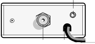
10.Connettore coassiale di antenna SO239: collegare in questa posizione un’antenna funzionante sulla frequenza di 27 MHz;
11.Cavo di alimentazione: Inserire il cavo di alimentazione accendisigari da 12V nella relativa presa accendisigari.
12.Altoparlante esterno EXT: presa per la connessione ad un altoparlante esterno (l’innesto dello spinotto esclude automaticamente l’altoparlante interno);
4 | |
M Zero Plus Manuale d’uso |

INSTALLAZIONE
Dadi
Dadi
Rondelle
Viti
Viti
Rondelle
Staffa
Rondelle
Viti e rondelle
Vite
Rondelle
Ricercare e localizzare sul mezzo mobile, la posizione per l’installazione dell’apparato. Tale posizionamento deve essere fatto in modo da non creare intralcio a chi guida, e nello stesso tempo, di facile accessibilità per poter togliere l’apparato secondo le necessità.
La posizione di montaggio più comune è sotto il cruscotto (si sconsiglia vicino a fonti di calore o vicino al condizionatore). Dopo aver stabilito la posizione più adatta sul veicolo, mantenere il ricetrasmettitore con la stafa di montaggio nell’esatta posizione desiderata e verificare che non ci siano inconvenienti; successivamente segnare e forare il veicolo per il fissaggio delle viti di montaggio. Controllare che esse siano ben ancorate, in considerazione delle notevoli sollecitazioni e vibrazioni create dal mezzo mobile.
M Zero Plus Manuale d’uso |
| 5 |

ANT |
EXT |
|
|
|
13,8V DC |
Inserire il cavo di alimentazione accendisigari da 12V nella relativa presa accendisigari. Prima di operare, installare e collegare l’antenna inserendo il connettore nell’apposita presa sul retro dell’apparato. Per l’uso di un altoparlante esterno, utilizzare la presa EXT-SPKR.
SOSTITUZIONE DEL FUSIBILE
Sostituire il fusibile del cavo di alimentazione con un similare a 2 A (Un fusibile di ricambio è in dotazione).
CONNESSIONE DEL MICROFONO
La presa del microfono è situata sul davanti dell’apparato. Accertarsi sempre che il connettore sia ben connesso alla presa.
6 | |
M Zero Plus Manuale d’uso |
MONTAGGIO ANTENNA
L’antenna è l’elemento più importante per ottenere i migliori risultati. È indispensabile che l’antenna abbia un’impedenza di 50 Ohm. A seconda della posizione in cui viene installata, il rendimento varia notevolmente. Usare un cavo coassiale con impedenza 50 Ohm. Sono consigliati i cavi RG 58U per lunghezza sotto i 2.5 metri, oppure RG 8 per lunghezze superiori. Il cavo coassiale deve essere montato con molta cura: evitare curve e piegamenti. Inoltre va ricordato che il cavo più corto aumenta la sensibilità dell’apparato, così pure un cattivo collegamento tra apparato e antenna.
Consigli:
•Montare l’antenna nel posto più libero e più alto dell’auto.
•L’antenna deve essere installata in posizione verticale, e così deve rimanere anche quando il veicolo è in moto.
•Montare l’antenna e il cavo il più possibile lontano da fonti di rumore.
•La massa dell’antenna deve coprire un’area di 1m2.
Esistono in commercio diversi tipi di antenna: con stilo a 1/4 d’onda; alimentate al centro; con carica in base; con carica in alto. Le antenne caricate sono più corte, ma per un miglior rendimento si consigliano quelle di lunghezza di circa 2 metri.
L’installazione a centro tetto è la migliore in senso assoluto perché il ground o radiale di terra è proporzionale in tutte le direzioni, mentre su una fiancata o in una qualsiasi altra parte del veicolo, diventa proporzionale alla massa dello stesso (es: se l’antenna è installata posteriormente, diventa direttiva in avanti, cioè i segnali provenienti dalla parte opposta sono meglio ricevuti, così dicasi anche per quelli trasmessi).
N.B.: con l’ausilio di un accoppiatore a due vie, l’antenna montata anteriormente può sostituire l’antenna della radio FM.
M Zero Plus Manuale d’uso |
| 7 |
POSIZIONI COMUNI DI MONTAGGIO DELL’ANTENNA
ANTENNA BASE
Per l’utilizzo del ricetrasmettitore in stazione fissa (base) occorre un alimentatore con una tensione di 12,6V ± 10% capace di erogare una corrente continua di 2A. Si consiglia un’antenna 1/2 onda omnidirezionale per comunicazioni a medio e lungo raggio.
8 | |
M Zero Plus Manuale d’uso |
USO DEL RICETRASMETTITORE
Ricezione
1.Assicurarsi che la presa accendisigari sia inserita nell’apposita presa a 12V.
2.Controllare che l’antenna e il microfono siano ben connessi.
3.Posizionare il commutatore d’emergenza sulla posizione CH.
4.Girare la manopola squelch nella massima posizione antioraria.
5.Accendere l’apparato mediante la manopola VOLUME.
6.Girare la manopola RF GAIN nella massima posizione oraria.
7.Ricercare il canale desiderato attraverso i tasti CHANNEL.
8.Regolare il volume come desiderato.
9.Regolare lo squelch. Questo comando viene utilizzato per eliminare il rumore di fondo del ricevitore in assenza di segnali d’ingresso. Per la massima sensibilità del ricevitore è preferibile che il comando sia regolato solo al preciso livello dove il rumore di fondo del ricevitore o il rumore ambientale, viene eliminato. Girare completamente in senso antiorario poi lentamente in senso orario finché non scomparirà il rumore. Qualsiasi segnale afnché possa venir ricevuto, dovrà essere leggermente più intenso rispetto alla media del rumore ricevuto. Un’ulteriore rotazione in senso orario aumenterà il livello di soglia che il segnale dovrà superare per poter essere udito. Se lo squelch sarà posizionato nella massima posizione in senso orario, si potranno sentire solo segnali molto forti.
Trasmissione
1.Selezionare il canale ed il modo di emissione (AM/FM) desiderato.
2.Premere il pulsante di trasmissione sul microfono, parlare mantenendo una distanza dalle labbra dai 5 a 8 cm.
3.Per ricevere, rilasciare il pulsante di trasmissione.
N.B.: gridare nel microfono non aumenta la portata della trasmissione, in quanto un circuito interno automaticamente commuta la massima modulazione. Si consiglia quindi di usare un tono di voce normale.
M Zero Plus Manuale d’uso |
| 9 |
IMPOSTAZIONE BANDA Po/St
1.Premere e tenere premuto i tasti UP/DOWN mentre si accende l’apparecchio;
2.Premere UP o DOWN per selezionare la banda desiderata: Po = Polonia (40 Ch AM/FM - 26.960/27.400) - St =Europa (40 CH AM/FM - 26.965/27.405)
3.Premere PTT per uscire dalla selezione.
SCORRIMENTO RAPIDO DEI CANALI
Per scorrere velocemente i canali, tenere premuto per circa 6 secondi il tasto UP o DOWN.
BEEP PRESSIONE TASTI
Quando questa funzione é attiva la radio emette un beep audio ogni volta che si preme un tasto.
Per abilitare/disabilitare il beep:
1.tenere premuto il tasto UP ed accendere la radio;
2.rilasciare e premere i tasti UP o DOWN per abilitare o disabilitare il beep;
3.il display mostrerà ‘ON’ quando il beep è attivo o ‘OF’ quando il beep è disattivato.
MEMORIZZAZIONE CANALE DI EMERGENZA
Il canale di emergenza impostato di default è il 19; per cambiare il canale operare come segue:
1.spostare il comando CH/EMG nella posizione EMG;
2.sul display lampeggia il canale di emergenza attuale;
3.premere contemporaneamente i tasti UP e DOWN per circa 5 secondi. Il display smette di lampeggiare;
4.selezionare il nuovo canale di emergenza con i tasti UP e DOWN;
5.premere nuovamente i due tasti UP e DOWN per circa 5 secondi;
6.il display lampeggerà nuovamente ed indicherà il canale di emergenza memorizzato.
10 | |
M Zero Plus Manuale d’uso |
ALTOPARLANTE SUPPLEMENTARE EXT
Inserire un altoparlante con potenza da 3 a 10 Watt nella presa EXT.
Il collegamento ad un altoparlante esterno esclude automaticamente quello interno.
M Zero Plus Manuale d’uso |
| 11 |
CARATTERISTICHE TECNICHE
RICEVITORE |
|
Gamma di frequenza............................................ |
da 26.965 a 27.405MHz (Europa) |
............................................................................... |
da 26.460 a 27.400MHz (Polonia) |
Sensibilità ................................................................. |
migliore di 1.0 µV per 20 dB S/N |
Reiezione canali adiacenti...................................... |
60 dB (10 KHz); 70 dB (20 KHz) |
Frequenze IF........................................................ |
1° IF=10.695 MHz; 2° IF=455 KHz |
Potenza d’uscita audio....................................................................................... |
2 W max |
Risposta in frequenza .................................................................... |
6 dB:450-2500 Hz |
Modulazione incrociata................................................................................ |
45 dB o più |
Squelch................................................................................. |
regolabile da 1.2 µV a 1mV |
Ciclo di utilizzo..................................................................................................... |
5/5/90 |
TRASMETTITORE |
|
Gamma di frequenza............................................ |
da 26.965 a 27.405MHz (Europa) |
............................................................................... |
da 26.460 a 27.400MHz (Polonia) |
Potenza d’uscita........................................................................................................ |
4 W |
Modulazione........................................................................................................ |
AM/FM |
Modulazione massima .............................................................................................. |
90% |
Deviazione massima ............................................................................................ |
1.9 KHz |
Emissioni spurie ............................................................................................ |
62 dB o più |
Tolleranza di frequenza............................................................................ |
più di 0.002% |
Alimentazione............................................................................................ |
12,6 V ± 10% |
Corrente assorbita max.............................................................................................. |
2 A |
Impedenza antenna ........................................................................................... |
50 Ohm |
Dimensioni........................................................................................... |
110x45x140 mm |
Peso ......................................................................................................................... |
665 g |
Le specifiche sono soggette a modifiche senza preavviso.
Un dispositivo di sezionamento adatto deve essere previsto nell’impianto elettrico. Tale dispositivo deve disconnettere entrambi i poli simultaneamente.
12 | |
M Zero Plus Manuale d’uso |
MAIN FUNCTIONS |
2 |
CONTROLS AND FUNCTIONS |
3 |
INSTALLATION |
5 |
REPLACING FUSE |
6 |
CONNECTING THE MICROPHONE |
6 |
BASE STATION ANTENNA |
9 |
USING YOUR TRANSCEIVER |
9 |
SELECTION OF Po/St BANDS |
10 |
QUICK SCROLL |
10 |
KEYPAD BEEP |
11 |
EMERGENCY CHANNEL MEMORY |
11 |
EXTERNAL SPEAKER |
11 |
TECHNICAL SPECIFICATIONS |
12 |
M Zero Plus Instruction Guide |
| 1 |
MAIN FUNCTIONS
•Display showing the channel in use;
•RF GAIN: adjusts the rx sensitivity. By turning the knob clockwise the rx sensitivity will increase; by turning counter-clockwise it will be reduced (this is very helpful in case of strong signals received);
•SQUELCH: the squelch eliminates the background noise in rx. To get the best sensitivity in rx the squelch should be adjusted exactly at the level when the background noise disappears;
•CH/EMG: this knob allows to switch immediately to the emergency channel. The emergency channel can be set by the user.
2 | |
M Zero Plus Instruction Guide |

CONTROLS AND FUNCTIONS
9 |
8 |
7 |
6 |
5
1 |
2 |
3 |
4 |
1.PIN mike connector: Connect the microphone to this jack;
2.RF GAIN knob: Adjusts the receiver gain;
3.SQUELCH knob: Adjusts the squelch threshold;
4.ON/OFF-VOLUME selector: turn the knob to switch on/of the radio and to adjust the volume at the desired level;
5.UP/DOWN controls: push the buttons to select the desired channel;
6.Channel display: it shows the channel in use;
7.TX led: the led lights up when you push the PTT button on the microphone;
8.CH-EMG: Channel in use /Emergency channel. This selector allows to switch quickly between the emergency channel and the channel in use;
9.AM/FM selector: to select AM or FM modulation.
M Zero Plus Instruction Guide |
| 3 |

|
12 |
ANT |
EXT |
|
|
|
13,8V DC |
10 11
10.Antenna coaxial connector SO239: connect here an antenna operating on 27 MHz;
11.Power supply cable: insert the power cable with lighter plug into the vehicle’s cigarette lighter cord.
12.External speaker jack. If you connect an external speaker, the internal one is automatically excluded.
4 | |
M Zero Plus Instruction Guide |
INSTALLATION
Nuts
Nuts
Washers
Screws
Screws
Washers
Washers |
Bracket |
|
|
Screws and |
|
washers |
|
|
Screws |
|
Washers |
Safety and convenience are the primary consideration for mounting any piece of mobile equipment. All controls must be readily available to the operator without interfering with the movements necessary for safe operation of the vehicle. Be sure all cables are clear of the brake, clutch and accelerator. Also, thought must be given to the convenience and comfort of passengers.
Another extremely important requirement is the ease of installation and removal for those occasions when you might want to remove the unit for service and maintenance.
The most common mounting position for a transceiver is under the dashboard directly over the drive shaft hump. Do not mount the transceiver in the path of the heater or air conditioning air stream. Take your time and plan your installation carefully. When you have determined the best location for mounting, use the mounting bracket as a template to mark mounting holes. Take care when you drill the holes that you do not drill into wiring, trim or other accessories.
M Zero Plus Instruction Guide |
| 5 |

ANT |
EXT |
|
|
|
13,8V DC |
Mount in position with bolts, lock washers and nuts or self-threading screws. You can install this transceiver in any location where 12,6 Vdc ± 10% power is available. Insert the power cable with lighter plug into the vehicle’s cigarette lighter cord. Before operation, you must install and connect your antenna system. The lead from the antenna you’ve installed should be connected to the antenna coaxial connector. If you are using an external speaker, connect it to the EXT-SPKR jack.
REPLACING FUSE
If you replace the fuse for DC Power Cord, use 2 A type (one is supplied as spare). Hold the fuse holder and press on the inside, then rotate the holder.
CONNECTING THE MICROPHONE
Your transceiver has a new microphone connector. This ensures that you won’t accidentally pull out or loosen the plug connection when moving the microphone cable out.
6 | |
M Zero Plus Instruction Guide |
ANTENNA SYSTEM
A mobile antenna system is not limited only to the antenna. The transmission line as well as the vehicle are important factors in the total antenna system. Therefore, you must use the correct type of transmission line and mount the antenna securely in a position that will give you optimal results. Use coaxial cable with an impedance of 50 Ohms. We suggest type RG 58/U for lengths under 2.5 m or RG 8/U for longer lengths. Generally speaking, you should keep the length of the transmission line to a minimum. The above discussion is as important for reception as for the transmission. If a mismatch exists between the antenna and the receiver, the excellent sensitivity and signal-to-noise radio of the receiver circuit will be defeated.
Suggestions
A few general rules should help you to install any mobile antenna properly.
•Keep it as far as possible from the main bulk of the vehicle.
•During operation, it must be vertical, and rigid enough to remain vertical when the vehicle or boat is in motion.
•Mount it as far as possible from sources of noise (ignition system, gauges, etc.) and keep the transmission line away from these noise sources.
•An antenna mounted in a boat requires a good ground connection. This can be either a metal hull or a ground made of tin-foil or copper sheeting.
This ground should cover an area of at least 1 m2 or more. Be sure the transceiver also has an adequate ground. There are many types of mobile CB antennas: a full quarter-wave length whip, a centerloaded whip, top loaded whip and the base loaded type are typical. A vertically polarized whip antenna is best suited for mobile service. It is omnidirectional. If it’s the loaded type, you will find it a physically shorter antenna. But, for greater efciency the 2.5 m long, full quarter-wave whip is better. Antenna length is directly related to efciency.
Generally, the longer it is, the more efcient will be.
There are many possible antenna locations on a car.
Four of the most popular are shown and discussed on the following.
Roof Mount
In this position the antenna radiates equally in all directions. Since the normal 1/2 wavelength whip antenna is too long for roof mounting on a vehicle, the antenna is shortened and loading coil is used to provide the proper electrical length. Our fiberglass roof mount is a good durable antenna.
Front Cowl Mount
The radiation pattern is slightly greater in the direction of the rear fender opposite the side on which the antenna is mounted. However, the front position ofers a number of advantages. The CB antenna can be easily mounted. It can double as both the CB and the standard auto radio an-
M Zero Plus Instruction Guide |
| 7 |

tenna by employing a two-way coupler. Ask about our complete line of antennas.
Rear Deck Mount
The radiation pattern is stronger in the direction of the front fender opposite the side on which the antenna is mounted. In this position you can use a full quarter-wave antenna or a shorter loaded whip. Here you might consider one of the full 2.5 meters whips.
Bumper Mount
The antenna radiates in a pattern directly in front of and to the rear of the vehicle, with maximum radiation directly away from the vehicle, in a horizontal plane. Despite its fairly irregular pattern, a bumpermounted full-length whip antenna will normally give the best results. Removing the antenna is simple and will leave no holes in the car.
BASE STATION ANTENNA
While your Transceiver is designed for mobile operation, you might wish to use it as a base station unit, in conjunction with a 12,6 Vdc ± 10% 2 A DC power supply. If you decide to use your Transceiver as a base station, choose an antenna designed to operate most efciently as a base station antenna. For example, the 1/2 wave antenna is a high-efciency radiator with omnidirectional characteristics. It performs as well in most applications as the ground plane does. You can use this type of antenna for medium-long range communications.
8 | |
M Zero Plus Instruction Guide |
USING YOUR TRANSCEIVER
Do not transmit without a suitable antenna or 50 Ohm load connected to the antenna connector.
To receive:
13.Make sure that the cigarette lighter plug is properly inserted into a 12V power socket.
14.Make sure that the antenna and the microphone are attached.
15.The emergency knob must be set to the CH position.
16.Set the Squelch control to maximum counterclockwise position.
17.Turn on the unit by rotating the VOLUME control clockwise.
18.Turn the RF-GAIN knob totally clockwise.
19.Set channel selector to the desired channel.
20.Adjust VOLUME for a suitable listening level.
21.Adjust Squelch to cut out annoying background noise when no signal is being received.
To do this, set the Channel Selector to a channel where no signals are present or wait until signals cease on your channel. Then, rotate the Squelch control in a clockwise direction to the point where the background noise just stops. Now, when a signal is present, you will hear it, but will not be disturbed by noise on the channel between signals. When properly set, the Squelch keeps the receiver “dead” until a signal comes in on that channel. However, do not set the Squelch too high, or weak signals will not be able to open the Squelch circuit. To receive very weak signals, it is best to leave Squelch set to the minimum position by rotating the control maximum counterclockwise. The Squelch circuit in your transceiver is an advanced design. It uses an operational amp IC to accomplish a hysteresis action. The result is that when you set the Squelch for a precise signal level, if that signal level increases or decreases in strength, the Squelch circuit will follow this change. With conventional Squelch circuit, often a signal which changes strength get “chopped” by the Squelch circuit and you lose a portion of the message. With a hysteresis Squelch, you get it all.
To Transmit:
1.Select the desired channel and the modulation (AM or FM).
2.Press the push-to talk button on the microphone and hold it an angle about 5-7 cm from your mouth and speak in a normal voice.
3.To receive, release the push-to-talk button. Be sure the mic plug is firmly connected to the jack.
M Zero Plus Instruction Guide |
| 9 |
NOTE: shouting into the mic will not increase your power or signal. An internal circuit automatically sets the mic signal for maximum modulation, so speak loudly will give no advantage.
SELECTION OF Po/St BANDS
1.Turn on the radio while keeping pressed the UP/DOWN controls
2.With the UP / DOWN buttons select the desired band: Po = Poland (40 Ch AM/FM - 26.960/27.400) - St =Europe (40 CH AM/FM - 26.965/27.405)
3.Push PTT to exit the selection
QUICK SCROLL
To scroll the channels, keep pressed the UP or DOWN controls for 6 seconds.
KEYPAD BEEP
When this function is enabled, you will hear a beep tone everytime a button is pressed. To activate/deactivate the beep tone:
1.keep pressed the UP button while turning on the radio;
2.press UP or DOWN to enable/disable the beep;
3.when the beep tone is enabled, the display will show ‘ON’ and when it’s disabled, ‘OF’ will be displayed.
EMERGENCY CHANNEL MEMORY
The emergency channel set by default is channel 19; to change it, follow these steps:
1.move the knob of the CH/EMG selector to EMG position;
2.the current emergency channel blinks on the display;
3.press the UP / DOWN controls for 5 seconds at the same time. The display will stop blinking;
4.with the UP/DOWN buttons select the new emergency channel;
5.push again UP / DOWN for about 5 seconds;
6.the display will blink again and will indicate the new emergency channel memory.
10 | |
M Zero Plus Instruction Guide |
EXTERNAL SPEAKER
Connect a speaker with a power of 3-10 Watt to the EXT jack.
When you connect an external speaker to the radio, the internal speaker is automatically disconnected.
M Zero Plus Instruction Guide |
| 11 |
TECHNICAL SPECIFICATIONS
RECEIVER |
|
Frequency coverage............................................... |
26.965 to 27.405 MHz (Europe) |
.................................................................................. |
26.960 to 27.400 MHz (Poland) |
Sensitivity......................................................... |
better than 1.0 µV for 20 dB SINAD |
Adjacent Channel Rejection ............................. |
60 dB at 10 kHz; 70 dB for 20 KHz |
Intermediate Frequency................................. |
1st IF=10.695 MHz; 2nd IF=455 KHz |
Audio Output power.................................................................................... |
2 watts max |
Frequency Response (6dB)................................................................... |
450-2500 Hz |
Cross Modulation.................................................................................. |
45 dB or better |
Squelch........................................................................... |
adjustable from 1.2 µV to 1mV |
Duty cycle............................................................................................................ |
5/5/90 |
TRANSMITTER |
|
Frequency coverage............................................... |
26.965 to 27.405 MHz (Europe) |
.................................................................................. |
26.960 to 27.400 MHz (Poland) |
Output Power........................................................................................................... |
4 W |
Type of modulation............................................................................................. |
AM/FM |
Max modulation........................................................................................................ |
90% |
Max deviation....................................................................................................... |
1.9 KHz |
Spurious Radiation ................................................................................ |
62 dB or better |
Frequency Tolerance..................................................................... |
better than 0.002% |
Antenna impedance .......................................................................................... |
50 Ohm |
Power supply....................................................................................... |
12,6 V ± 10%max |
Max Current Drain..................................................................................................... |
2A |
Dimensions .......................................................................................... |
110x45x140 mm |
Weight ..................................................................................................................... |
665 g |
Specifications are subject to change without notice.
A readily accessible disconnect device shall be incorporated in the installation wiring. The disconnect device shall disconnect both poles simultaneously.
12 | |
M Zero Plus Instruction Guide |
HAUPTFUNKTIONEN |
2 |
BEDIENUNG UND FUNKTIONEN |
3 |
INSTALLATION |
5 |
MIKROFONANSCHLUSS |
7 |
MONTAGE DER ANTENNE |
7 |
EMPFEHLUNGEN |
7 |
FESTSTATION |
8 |
BEDIENUNG IHRES FUNKGERÄTES |
9 |
AUSWAHL DER PO / ST BÄNDER |
10 |
QUICK SCROLL |
10 |
TASTENTON |
10 |
NOTRUFKANAL-SPEICHER |
10 |
EXTERNER LAUTSPRECHER |
11 |
TECHNISCHE DATEN |
12 |
M Zero Plus Bedienungsanleitung |
| 1 |
 Loading...