


INDICE
Introduzione.................................................................................................................... |
Pag.1 |
Descrizione comandi...................................................................................................... |
Pag.2 |
Installazione.................................................................................................................... |
Pag.5 |
Collegamento elettrico................................................................................................... |
Pag.5 |
Installazione dell'antenna............................................................................................... |
Pag.5 |
Uso di MIDLAND 248.................................................................................................... |
Pag.6 |
Selezione bande di frequenza....................................................................................... |
Pag.6 |
Tabella bande di frequenza............................................................................................ |
Pag.6 |
Caratteristiche tecniche.................................................................................................. |
Pag.7 |
MIDLAND 248 operante sui canali della banda cittadina, ha come importante ed innovativa peculiarità di essere controllato a microprocessore. Frutto delle più avanzate tecnologie, garantisce il massimo delle prestazioni e del rendimento. Apparato di ottima qualità, è stato costruito utilizzando i migliori componenti. La circuiteria, tutta allo stato solido, è montata su robusti circuiti stampati, garantendo un uso per molti anni anche nelle situazioni più gravose. MIDLAND 248 è sintetizzato in frequenza tramite circuito PLL, soluzione che permette di generare, tramite un quarzo le frequenze richieste, consentendo una maggior affidabilità e flessibilità nel controllo delle stesse.
MIDLAND 248 è inoltre dotato del dispositivo “NOISE BLANKER” (soppressore dinamico dei disturbi) che permette di ridurre notevolmente i disturbi audio (fino al 95%) facilitando l’ascolto anche quando il segnale è disturbato.
ITALIANO
1

ITALIANO
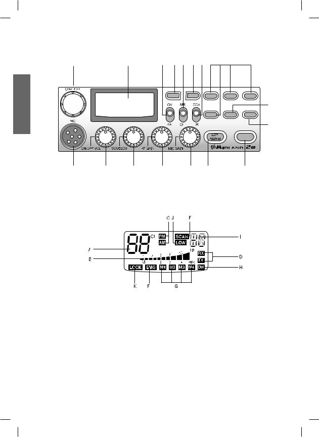
DESCRIZIONE COMANDI
1 |
3 |
12 |
10 13 |
11 14 |
8 |
Q.UP |
Q.DOWN |
M1 |
M2 |
M3 |
|
|
|
|
17 |
|
|
M4 |
DW |
EMG |
|
|
|
|
9 |
SCAN
2 |
4 |
5 |
6 |
7 |
15 |
16 |
1.Ricerca manuale canali
2.Presa microfono: Inserire lo spinotto nell’apposita presa.
3.Display retroilluminato multifunzione
A.Numero canali selezionati
B.Indicatore di intensità del segnale ricevuto e di potenza di segnale trasmesso
C.AM/FM: indicatore del modo di emissione
D.RX/TX: indicatore ricezione (RX) e trasmissione (TX)
E.SCAN: indicatore funzione SCAN attivata
F.EMG: indicatore lampeggiante canale d’emergenza attivato
G.M1-M2-M3-M4: indicatori memorie canali
H.DW: funzione Dual Watch attivata
I.Indica la banda di frequenza selezionata.
J.LOW: viene visualizzato quando la radio trasmette in bassa potenza (condizione che si verifica solo per determinate bande di frequenza – vedi tabella bande).
K.LOCK: Attivazione del blocco tastiera (UP/DOWN) del microfono.
4.Manopola ON/OFF-VOLUME: Posizione ‘’OFF’’:Apparato spento; Posizione ‘’Volume’’: Ruotando la manopola, regolare il volume al livello desiderato. Con il selettore ‘’PA-
2

CB’’. Accensione apparato: in posizione ‘’PA’’, la manopola regola il livello di uscita di bassa frequenza.
5.Manopola ‘’Squelch’’ regolazione livello di soglia della ricezione: per la massima sensibilità del ricevitore è preferibile che il comando sia regolato solo al preciso livello dove il rumore di fondo del ricevitore viene eliminato.
6.Manopola ‘’RF-GAIN’’: Controllo della sensibilità in ricezione: ruotando la manopola in senso orario, si ottiene un’aumento della sensibilità; ruotandola in senso antiorario, si ottiene una diminuzione della sensibilità. Ciò è utile in presenza di forti segnali.
7.Manopola ‘’MIC-GAIN’’: Controllo dell’amplificazione microfonica in trasmissione: utilizzare il microfono ricercando sperimentalmente la posizione ottimale sia come distanza dalla bocca, che di livello di amplificazione, in modo da ottenere la migliore modulazione possibile.
8.Pulsanti ‘’M1-M2-M3-M4'’: Questi pulsanti permettono di memorizzare e di richiamare all’occorrenza 4 canali a piacimento precedentemente memorizzati. Per memorizzare i canali: selezionare il canale desiderato tramite la manopola CHANNEL o i tasti UP/ DOWN. Premere M1 per circa 3 secondi per memorizzare il canale prescelto nella memoria M1. Ripetere le stesse operazioni per le altre memorie a disposizione.
9.Pulsante "EMG": Canale d’emergenza: premendo questo tasto si ci posizionerà automaticamente sul canale 9 (canale d’emergenza). Sul display lampeggerà “EMG” e non
sarà possibile cambiare accidentalmente il canale.
10/11. PULSANTI “Q.UP/Q.DOWN’’: Per selezionare rapidamente i canali verso l’alto (UP) o verso il basso (DOWN).
12.Selettore ‘’CB-PA’’: Posizione ‘’CB’’: in questa posizione, l’apparato è attivo come ricetrasmettitore; posizione ‘’PA’’: questo modo di funzionamento è possibile solo se viene collegato un altoparlante alla presa PA sul retro. In questo caso la manopola ‘’Volume’’ viene usata come controllo dell’amplificazione.
13.Selettore ‘’ANL/OFF’’: Posizione ‘’ANL’’: si attiva il limitatore automatico di rumore. È utile per eliminare i disturbi di tipo impulsivo (generati ad esempio dal motore dell’auto). Posizione OFF: disattivato.
14.Selettore "Local/DX": attenuatore di segnale. LOCAL: per ricevere solo segnali forti; DX: per segnali deboli.
15.Pulsante “AM/FM”(LCR): Per selezionare il modo di emissione (AM/FM). Se lo si preme all’accensione con il tasto “SCAN”, seleziona la banda operativa. Le relative scelte saranno visualizzate sul display. Se si seleziona un banda di frequenza che opera solamente la modalità FM, il tasto “AM/FM” attiva la funzione LCR (richiamo ultimo canale selezionato).
16.Pulsante "SCAN": tramite questo comando si potrà ricercare automaticamente un canale occupato.
•Ruotare lo Squelch in senso orario fino a quando non sparisce il rumore di fondo.
•Premere il pulsante "SCAN". Il ricetrasmettitore scansionerà automaticamente e
ripetutamente tutti i canali fino a quando non troverà un canale occupato.
Se lo si preme all’accensione con il tasto “AM/FM”, seleziona la banda operativa. Le relative scelte saranno visualizzate sul display.
17.Tasto DW: con questo tasto é possibile rimanere sintonizzati contemporaneamente su due canali a scelta dell’utente.
Questa funzione permette il monitoraggio di un secondo canale. In presenza di un segnale sul secondo canale, il ricevitore commuterà automaticamente su quest’ultimo. Il monitoraggio riprenderà dopo 4 secondi dal cessare del segnale.
Per attivare la funzione Dual Watch, operare come segue:
ITALIANO
3
ITALIANO |
a. Selezionare il canale desiderato mediante il selettore canali. |
|
|
|
|
||||
|
|
|
|
|
|||||
|
b. Premere il tasto “DW” (sul display lampeggia la sigla DW). |
|
|
|
|
||||
|
c. Selezionare il secondo canale. |
|
|
|
|
|
|
|
|
|
d. Premere nuovamente il tasto “DW”: la scritta DW smetterà di lampeggiare e sarà |
||||||||
|
evidenziata sul display in modo fisso. |
|
|
|
|
|
|
|
|
|
e. Per annullare la funzione premere “DW”. |
|
|
|
|
|
|
|
|
|
|
|
|
|
|
|
|
|
|
|
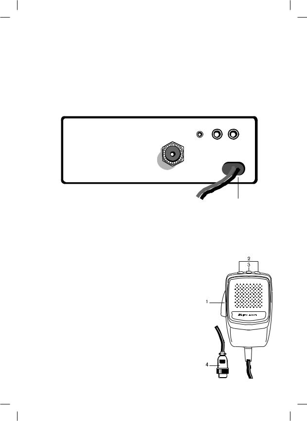
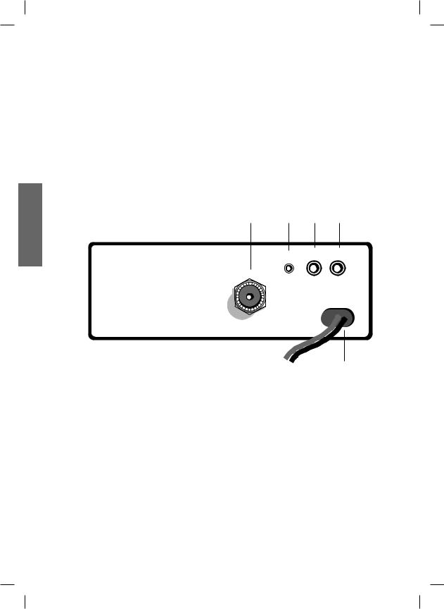
PANNELLO POSTERIORE |
19 |
20 |
21 |
22 |
||||
|
|
|
|
|
|
|
|
|
|
|
|
|
|
|
|
PA |
EXT |
||
|
|
|
|
S-METER |
|||||
|
|
|
|
|
|
|
|
|
|
|
|
ANTENNA |
|
|
|
|
|
|
|
POWER 13,2 V DC
23
18. CONNETTORE ANTENNA: È previsto il connettore SO 239.
19. PRESA S. METER: Permette il collegamento di uno strumento esterno.
20. PRESA PA: Tramite il collegamento ad un altoparlante esterno, permette di utilizzare l’apparato come amplificatore audio.
21. PRESA EXT: Presa altoparlante esterno (questo collegamento esclude l’uso dell’altoparlante interno).
22. POWER 12.6 Vdc: presa di alimentazione.
MICROFONO
1.PTT: Pulsante di trasmissione
2.Pulsanti UP/DOWN: selezione canali verso l’alto (UP) e verso il basso (DN)
3.Tasto LOCK: permette di bloccare i tasti UP/ DOWN del microfono.
4.Connettore microfonico 6 PIN
4

INSTALLAZIONE
Ricercare e localizzare, sul mezzo mobile, la posizione per installare l’apparato, utilizzando la staffa di supporto in dotazione o, eventualmente, un estraibile. Tale posizionamento deve essere fatto in modo da non creare intralcio a chi guida, ma deve anche essere facilmente accessibile. Praticare i fori (diametro di circa 3 mm) nella carrozzeria per il fissaggio con le viti. Posizionare l’apparato nella staffa di fissaggio. Controllare che le viti siano ben serrate, in considerazione delle notevoli vibrazioni create dal mezzo mobile.
COLLEGAMENTO ELETTRICO
Prima di procedere in questa operazione, controllare che il ricetrasmettitore sia spento (posizione OFF= la manopola del volume completamente girata a sinistra, dopo lo scatto).
L’apparato è dotato di un cavetto di alimentazione bicolore con un portafusibile inserito sul cavo rosso (positivo). Nel collegamento, è molto importante rispettare la polarità anche se l’apparato è protetto contro l’inversione accidentale. Di norma si identifica il polo positivo con il colore rosso o con il segno ‘’+’’, e il polo negativo con il colore nero o con il segno “-”.
Gli stessi segni (o colori) identificativi li troveremo sulla batteria (accumulatore od altro) e nella scatola dei fusibili dell’automobile. Si raccomanda di collegare in modo corretto e stabile i terminali del cavetto alla batteria.
ATTENZIONE
Perl’ottimizzazionedelleprestazionisiconsiglial’installazionedell’apparecchiatura in luoghi che possano consentire un sufficiente riciclo d’aria.
INSTALLAZIONE DELL’ ANTENNA
Informazioni utili:
1.Installare l’ antenna nella parte più alta del veicolo.
2.Maggiore è la lunghezza dell’ antenna e migliore sarà il suo rendimento.
3.Se possibile, installare l’antenna al centro della superficie metallica scelta.
4.Tenere il cavo dell’antenna lontano da fonti di disturbi elettrici.
5.Assicurarsi di avere una buona massa.
6.Evitare danni ai cavi.
Attenzione: Non usare mai la radio CB senza aver installato un’antenna appropriata per non correre il rischio di danneggiare il trasmettitore; per la stessa ragione controllare periodicamente il ROS tramite l’apposito strumento.
SOSTITUZIONE DEL FUSIBILE
Sostituire il fusibile del cavo di alimentazione con un similare di tipo F 5A 250V. I parametri ed il simbolo del fusibile sono indicati nella seguente etichetta:
F5A 250V +
ITALIANO
5

ITALIANO
USO DEL MIDLAND 248
Dopo aver installato il vostro CB e la vostra antenna, seguire attentamente le seguenti istruzioni per raggiungere un funzionamento soddiafacente del vostro apparato.
1.Avvitare la spina nella presa del microfono sul pannello e controllare il montaggio.
2.Assicurarsi che l’antenna sia collegata al proprio connettore.
3.Assicurarsi che lo squelch sia completamente ruotato verso sinistra.
4.Accendere l’apparato e regolare il comando del volume per un buon livello sonoro.
5.Selezionare il canale desiderato.
6.Per trasmettere, premere il pulsante di trasmissione PTT sul microfono.
7.Per ricevere, rilasciarlo.
SELEZIONE BANDE DI FREQUENZA
La scelta delle bande di frequenza deve essere eseguita a seconda del paese nel quale si intende operare.
Procedimento:
1. Spegnere la radio.
2. Accendere l’apparecchio premendo contemporaneamente i tasti “AM/FM” e “SCAN”. 3. Ruotare la manopola “CHANNEL” e selezionare la banda di frequenza desiderata (vedi
tabella bande).
4. Premere il tasto “AM/FM” per terminare la selezione.
NOTA1: nella banda di frequenza UK è possibile selezionare direttamente la banda EC premendo il tasto “AM/FM” per 2 secondi circa.
NOTA2: Se si seleziona una banda di frequenza che opera solamente la modalità FM, il tasto “AM/FM” attiva la funzione LCR (richiamo ultimo canale selezionato).
Sigla sul display |
Paese |
I |
Italia 40 CH AM/FM 4Watt |
I2 |
Italia 34 CH AM/FM 4Watt |
D |
Germania 80 CH FM 4Watt / 12 CH AM 1Watt |
D2 |
Germania 40 CH FM 4Watt / 12 CH AM 1Watt |
D3 |
Germania 80 CH FM 4Watt / 40 CH AM 1Watt |
EU |
Europa 40 CH FM 4Watt / 40 CH AM 1Watt |
EC |
CEPT 40 CH FM 4Watt |
E |
Spagna 40 CH AM/FM 4Watt |
F |
Francia 40 CH FM 4Watt / 40 CH AM 1Watt |
PL |
Polonia 40 CH AM/FM 4W |
UK |
Inghilterra 40 CH FM 4 Watt frequenze inglesi + EC 40 CH FM |
|
4Watt frequenze CEPT |
Attenzione:
Lo standard sicuramente riconosciuto in tutti i paesi europei è 40CH FM 4W (EC) - Vedi tabella “Restrizioni all’uso”
6

CARATTERISTICHE TECNICHE
GENERALI
Canali....................................................................................................... |
(vedi tabella bande) |
Gamma di frequenza........................................................................ |
26.565 - 27.99125 MHz |
Ciclo di utilizzo (% su 1 ora)................................................. |
TX 5%; RX 5%; Stand-by 90% |
Controllo di frequenza ................................................................................................... |
a PLL |
Temperatura......................................................................................................... |
-10°/+55° C |
Tensione di alimentazione ............................................................................ |
12.6 Vcc ±10% |
Dimensione................................................................................. |
180 (L)x50 (H)x150 (P) mm |
Peso................................................................................................................................... |
1 kg |
RICEVITORE
Sistema ricevente........................................................ |
supereterodina a doppia conversione |
Frequenza intermedia................................................................................. |
I° IF: 10.695 MHz |
.......................................................................................................................... |
II° IF: 455 KHz |
Sensibilità............................................................................... |
0.5µV per 20 dB SINAD in FM |
................................................................................................ |
0.5µV per 20 dB SINAD in AM |
Potenza d’ uscita audio @10% THD............................................................ |
2.0 W @ 8 Ohm |
Distorsione audio............................................................................... |
meno dell’8% @ 1 KHz |
Reiezione alle immagini................................................................................................. |
65 dB |
Selettività sul canale....................................................................................................... |
65 dB |
Rapporto segnale disturbo............................................................................................. |
45 dB |
Assorbimento all’attesa................................................................................................ |
250mA |
TRASMETTITORE
Potenza d’uscita ........................................................................................................ |
4W max |
Modulazione............................................................................................. |
AM: da 85% a 95% |
............................................................................................................ |
FM: 1,8 KHz ± 0,2 KHz |
Frequenza di risposta....................................................................................... |
300 Hz/3 KHz |
Impedenza d’ uscita........................................................................... |
RF 50 Ohm sbilanciato |
Rapporto segnale disturbo..................................................................................... |
40 dB MIN |
Corrente assorbita.............................................................................................. |
max 2500mA |
Le specifiche sono soggette a modifiche senza preavviso.
Un dispositivo di sezionamento adatto deve essere previsto nell’impianto elettrico. Tale dispositivo deve disconnettere entrambi i poli simultaneamente.
ITALIANO
7


INDEX
Introduction............................................................................................................. |
Pag. 1 |
Function and location of the controls...................................................................... |
Pag. 2 |
Installation................................................................................................................ |
Pag.5 |
Power supply........................................................................................................... |
Pag.5 |
Installing an antenna................................................................................................ |
Pag.5 |
How to operate with your transceiver...................................................................... |
Pag.6 |
Frequency band selection........................................................................................ |
Pag.6 |
Frequency band chart.............................................................................................. |
Pag.6 |
Technical specifications........................................................................................... |
Pag.7 |
Your MIDLAND 248 represents the state-of-the art in high-tech engineering. Designed for the Citizen Band Mobile operation, this compact package is big in performance. It is a quality piece of electronic equipment, skillfully constructed with the finest components. The circuitry is all a solid-state, mounted on rugged printed circuit boards. It is designed for many years of reliable, trouble-free performance.The night-light buttons allow the night use.Your MIDLAND 248 has a built Channel Phase-Locked Loop synthesizer circuit.
The PLL circuit achieves a new technique for generating all the required frequencies with fewer crystals. The result is much tighter frequency control and superior reliability.
Midland 248 is equipped with the “NOISE BLANKER” (noise reducer device) that reduces considerably the audio noises up to 95%, allowing a clear communication even when the signal is disturbed.
ENGLISH
1
ENGLISH
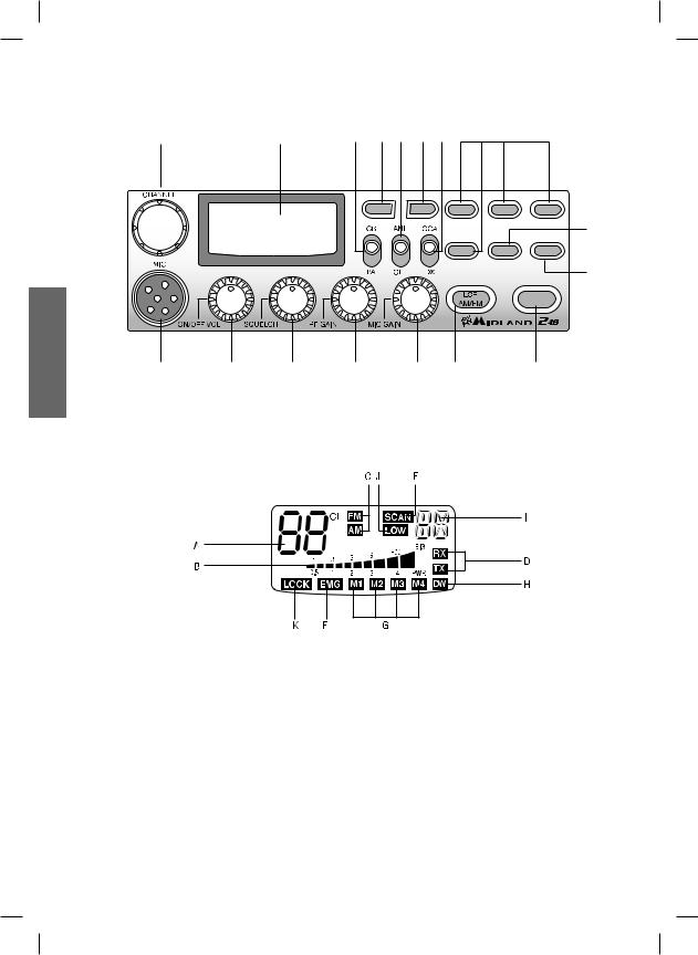
FUNCTION AND LOCATION OF THE CONTROLS
1 |
3 |
12 |
10 13 |
11 14 |
8 |
Q.UP |
Q.DOWN |
M1 |
M2 |
M3 |
|
|
|
|
17 |
|
|
M4 |
DW |
EMG |
|
|
|
|
9 |
SCAN
2 |
4 |
5 |
6 |
7 |
15 |
16 |
1.Channel selector
2.Microphone jack: Insert the mic connector into this jack.
3.Multifunction backlighted display.
A.Channel selected number
B.The received signal strength and the power of the transmitting signal
C.AM/FM mode
D.RX/TX: TX=transmit mode; RX=receive mode
E.SCAN mode
F.EMG mode
G.M1-M2-M3-M4: preset memory channels
H.DW: Dual Watch activated
I.Frequency band selected.
J.LOW: displayed when the radio transmits in low power (this mode is possible with some frequency bands only – see the frequency band chart).
K.LOCK: microphone (UP/DOWN buttons) lock enabled.
4.“ON/OFF Volume” Control: in ‘’off’’ position your transceiver is OFF. Turn this con-
2
|
trol clockwise to switch on the unit. Turn the knob clockwise a little more to set the |
|
|
audio level, until you get a comfortable reception. With ‘’PA-CB’’ selector set in ‘’PA’’ |
|
|
position, the knob controls the audio output level. |
|
5. |
“Squelch” Control: for the maximum receiver sensitivity, the control must be regu- |
|
|
lated exactly where the receiver background noise disappears. |
|
6. |
“RF” (Radio Frequency) Gain Control: it controls the reception sensitivity. To |
|
|
||
|
increase sensitivity, simply turn it clockwise. Sensitivity decreases turning it counter- |
ENGLISH |
|
clockwise. Low sensitivity is useful when very strong signals are present in the |
|
|
band. |
|
|
|
|
7. |
“Mic (Microphone) Gain Control”: in TX mode, it controls the microphone amplifi- |
|
|
cation. To get the best results, use the microphone and set the optimum position for |
|
|
both the distance from your mouth and for the amplification level, asking your partner |
|
|
when the modulation comes out better. |
|
8. |
“M1-M2-M3-M4” buttons: These buttons allow the storing and recalling of 4 pre- |
|
|
selected channels. How to store: select the desired channel and press M1 for at |
|
|
least 3 sec to store the choosen channel in the M1 memory. Repeat these steps to |
|
|
memorise the other presets. |
|
9. |
EMG button: Emergency channel. By pressing it, the unit will be automatically |
|
positioned on CH 9 (emergency channel). The display will show “EMG”. It will not be possibile to accidentally change the channel.
10/11. “Q. UP-Q. DOWN” buttons: To skip 10 channels up (Q. UP) or 10 channels down (Q. DOWN).
12.’’CB/PA’’ Selector. In the “CB” position, the unit operates as a transceiver. You can use the PA (public address) function only if you connect a speaker to the PA jack. In this case the ‘’Volume’’ knob controls the amplification level.
13.‘’ANL/OFF’’ Selector. In the ‘’ANL’’ position it activates an automatic noise limiter for the impulsive noises (caused by the engine of the car or other sources).
14."Local/DX" Selector ”Local” position: to receive strong signal only.”DX” position: to receive weak signals.
15.“AM/FM”(LCR) button: To select AM or FM mode. If you push it along with the “SCAN” button at the switching on of the radio, it selects the operating band, which will be displayed. If you select a frequency band operating in FM mode only, this button enables the LCR function (Last Channel Recall).
16.“SCAN” button: with this control, you can automatically seek for a busy channel. Turn the Squelch clockwise until the background noise is no longer heard.
Press the ‘’SCAN’’ button: the transceiver will scan automatically all the channels until a carrier is being received. If you push it along with the “AM/FM” button at the switching on of the radio, it selects the operating band, which will be displayed.
17.DW button: This feature allows you to scan 2 channels of your choice. When a signal on the second channel is picked up, the conversation on the first is automatically interrupted and the receiver switches on the second channel. The monitoring starts again 4 seconds after the carrier disappears.
To activate this function, operate as follows:
a.Select the desired channel through the channel selector.
b.Press the “DW” button (DW blinks on the display).
c.Select the second channel.
d.Push the “DW” button again: the reading DW will remain fixed.
e.To disable this function, press the “DW” control.
3
ENGLISH
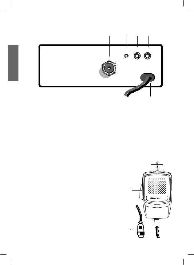
REAR PANEL
19 20 21 22
S-METER PA EXT
ANTENNA
POWER 13,2 V DC
23
18.Antenna connector (SO239 connector type).
19.S. Meter jack: it allows an external “S. Meter” connection.
20.“PA” jack: by connecting with an external loudspeaker, you can use the unit as an audio-amplifier.
21.”EXT” jack: external loudspeaker jack (the internal loudspeaker is excluded).
22.Power 12.6V DC: power supply cable.
MICROPHONE
1.PTT: transmission button
2.UP/DOWN buttons: manual channel selector
3.LOCK button: it allows you to lock the UP/DOWN buttons.
4.6 pin microphone connector
4

INSTALLATION
Safety and convenience are the primary consideration for mounting any piece of mobile equipment. All controls must readily available to the operator without interfering with the movements necessary for safe operation of the veicle. Set the proper position in the car to install the transceiver using the supplied supporting bracket or eventually the slide bracket. Tighten the retaining screws. The fixing bracket must be close to metallic parts.
POWER SUPPLY
Be sure the transceiver is off. In the direct-voltage power supply, is very important to observe the polarity even if the unit is protected against the accidental inversion:
Red = positive pole (+) Black = negative pole (-)
The same colors are present on the battery and in the fuse box of the car. Correctly connect the cable terminal to the battery.
ATTENTION
To obtain best performances we recommend to install the radio in a place with enough air circulation.
INSTALLING AN ANTENNA
1.Place the antenna as high as possible.
2.The longer is the antenna, the better will be the performance.
3.If possible, mount the antenna in the center of whatever surface you choose.
4.Keep antenna cable away from noise sources, such as the ignition switch, gauges, etc.
5.Make sure you have a solid metal-to-metal ground connection.
6.Prevent cable damage during antenna installation.
WARNING: To avoid damage, never operate your CB radio without connecting a proper antenna. A periodical control of the cable and of the S.W.R. is recommended.
REPLACING FUSE
If you replace the fuse for DC power Cord, use F 5A 250V type. The parameters and the symbol of the fuse are indicated in the following label.
F5A 250V +
ENGLISH
5

HOW TO OPERATE WITH YOUR TRANSCEIVER
|
1. |
Screw the microphone plug into the microphone jack. |
|
|
2. |
Make sure your antenna is securely connected to the antenna connector. |
|
|
3. |
Make sure the SQUELCH control is turned fully counterclockwise. |
|
|
4. |
Turn on the unit and adjust the volume control. |
|
ENGLISH |
5. |
Select your desired channel. |
|
6. |
To transmit, press the PTT button and speak in a normal tone of voice. |
||
7. To receive, release the PTT button. |
|||
|
|||
FREQUENCY BAND SELECTION
The frequency bands must be chosen according to the country where you are going to operate.
Procedure:
1.Switch off the unit.
2.Turn it on while pushing the “AM/FM” e “SCAN” buttons at the same time.
3.Rotate the “CHANNEL” knob and select the desired frequency band (see the chart here below).
4.To stop your selection, press the “AM/FM” button.
NOTE1: In the UK frequency band, you can select directly the EC band by pushing the “AM/FM” button for 2 seconds.
NOTE2: If you select a frequency band which operates in FM mode only, the “AM/FM” control enables the LCR function (Last Channel Recall).
FREQUENCY BAND CHART
Digits displayed |
Country |
I |
Italy 40 CH AM/FM 4Watt |
I2 |
Italy 34 CH AM/FM 4Watt |
D |
Germany 80 CH FM 4Watt / 12 CH AM 1Watt |
D2 |
Germany 40 CH FM 4Watt / 12 CH AM 1Watt |
D3 |
Germany 80 CH FM 4Watt / 40 CH AM 1Watt |
EU |
Europe 40 CH FM 4Watt / 40 CH AM 1Watt |
EC |
CEPT 40 CH FM 4Watt |
E |
Spain 40 CH AM/FM 4Watt |
F |
France 40 CH FM 4Watt / 40 CH AM 1Watt |
PL |
Poland 40 CH AM/FM 4Watt |
UK |
England 40 CH FM 4 Watt English frequencies + EC 40 CH FM |
|
4Watt CEPT frequencies |
ATTENTION!
The frequency band definitely allowed all over Europe is 40CH FM 4W (EC)
6

TECHNICAL SPECIFICATIONS
GENERAL
Channels ....................................................................... |
(see the frequency band chart) |
Frequency Range ...................................................................... |
26.565 - 27.99125 MHz |
Duty cycle (% on 1 hour)............................................... |
TX 5% - RX 5% - Stand-by 90% |
Frequency Control ..................................................................................................... |
PLL |
Operating Temperature Range...................................................................... |
-10°/+55° C |
DC input voltage ..................................................................................... |
12.6VDC ±10% |
Size....................................................................................... |
180 (L)x50 (H)x150 (P) mm |
Weight......................................................................................................................... |
1kg |
RECEIVER
Receiving system........................................................ |
dual conversion superheterodyne |
Intermediate frequency ............................................ |
I° IF: 10.695 MHz • II° IF: 455 KHz |
Sensitivity................................................................ |
0.5µV for 20 dB SINAD in FM mode |
................................................................................ |
0.5µV for 20 dB SINAD in AM mode |
Audio output power @10% THD............................................................. |
2.0 W @ 8 Ohm |
Audio distortion............................................................................ |
less than 8% @ 1 KHz |
Image rejection....................................................................................................... |
65 dB |
Adjacent channel rejection...................................................................................... |
65 dB |
Signal/Noise ratio.................................................................................................... |
45 dB |
Current drain at stand/by....................................................................................... |
250mA |
TRANSMITTER
Output power....................................................................................................... |
4W max |
Modulation...................................................................................... |
AM: from 85% to 95% |
...................................................................................................... |
FM:1,8 KHz ± 0,2 KHz |
Frequency response................................................................................... |
300 Hz/3 KHz |
Output impedance...................................................................... |
RF 50 Ohm unbalanced |
Signal/Noise Ratio........................................................................................... |
40 dB MIN |
Current drain............................................................................................... |
max 2500 mA |
Specifications are subject to change without notice.
A readily accessible disconnect device shall be incorporated in the installation wiring. The disconnect device shall disconnect both poles simultaneously.
ENGLISH
7


INHALT
Einführung.............................................................................................................. |
Seite 1 |
Funktion und Lage der Bedienelemente............................................................... |
Seite 2 |
Einbau des MIDLAND 248 im Kraftfahrzeug......................................................... |
Seite 5 |
Anschluß an die Spannungsversorgung................................................................ |
Seite 5 |
Montage der Antenne............................................................................................. |
Seite 5 |
Bedienung Ihres MIDLAND 248............................................................................ |
Seite 6 |
Auswahl der Frequenzbänder................................................................................ |
Seite 6 |
Frequenztabelle..................................................................................................... |
Seite 7 |
Technische Daten.................................................................................................. |
Seite 8 |
Ihr MIDLAND 248 verkörpert den aktuellen Stand der Entwicklung auf dem Gebiet der Funkgerätetechnik. Dank der kompakten Abmessungen und der kompromißlosen Auslegung für den Mobilbetrieb wird die besondere Leistungsfähigkeit auf allen CB-Kanälen sichergestellt. Sie haben ein elektronisches Qualitätsprodukt vor sich, das professionell konstruiert und mittels ausgesuchter, erstklassiger Komponenten gebaut worden ist. Leistungsfähige Halbleiter-technik mit aktueller PLL-Schaltung ermöglicht durch hohe Frequenzkonstanz sowie dem Aufbau auf einer stabilen Leiterplatte einen jahrelang störungsfreien Betrieb. Durch das Nachtdesign mit seiner dezenten Hintergrundbeleuchtung ist der Betrieb bei Dunkelheit komfortabel und sicher.
Die Funktion des NOISE BLANKER beruht auf einen optimierten Sprachfrequenzfilter, der sich automatisch in Abhängigkeit des empfangenden Sprachsignals einbzw. ausschaltet. Im eingeschalteten Zustand werden die stark störenden Rauschanteile eliminiert und speziell die Sprachfrequenzen bevorzugt.
DEUTSCH
1
DEUTSCH
FUNKTION UND LAGE DER BEDIENELEMENTE
1 |
3 |
12 |
10 13 |
11 14 |
8 |
Q.UP |
Q.DOWN |
M1 |
M2 |
M3 |
|
|
|
|
17 |
|
|
M4 |
DW |
EMG |
|
|
|
|
9 |
SCAN
2 |
4 |
5 |
6 |
7 |
15 |
16 |
1.Kanalwahlschalter: Mit diesem Schalter lassen sich alle 40 Kanäle einstellen.
2.Mikrofonbuchse: Hier wird der Stecker des Mikrofons eingesteckt.
3.MultifunktionsDisplay mit Hintergrundbeleuchtung.
Im Display werden die folgenden Informationen angezeigt:
A.Zweistellige Kanalanzeige
B.Relative Empfangsfeldstärke und Sendeleistung
C.AM/FM-Betriebsart
D.RX-/TX-Anzeige: TX=Sendebetrieb, RX=Empfangsbetrieb
E.SCAN-Betrieb, Suchlauf nach belegten Kanälen
F.EMG-Kanal, Fernfahrer-/Notruf-Kanal
G.M1, M2, M3, M4: frei wählbare Kanalspeicherplätze
H.DW: Zweikanalüberwachung (Dual Watch) aktiviert
I.Zeigt das gewählte Frequenzband an.
J.LOW: erscheint, wenn das Funkgerät auf niedrige Ausgangsleistung schaltet (betrifft nur bestimmte Frequenzbänder – siehe Frequenztabelle)
K.LOCK: Aktivierung der Mikrofon-Tastaturverriegelung (UP/DOWN) .
4.Ein/Aus-Schalter, Lautstärkeregler: In der Stellung “OFF” ist Ihr MIDLAND 248
2

|
ausgeschaltet. Durch Drehen des Reglers im Uhrzeigersinn wird das Gerät eingeschal- |
|
||
|
tet. Weiteres Drehen im Uhrzeigersinn erhöht die Wiedergabelautstärke nach Wunsch. |
|
||
|
Steht der PA-CB-Wahlschalter in der Stellung “PA” wird mit dem Lautstärkeregler die |
|
||
|
Durchsage-Lautstärke eingestellt. |
|
|
|
5. |
Rauschsperre, Squelch: Um die höchstmögliche Empfangsempfindlichkeit zu nutzen, |
|
||
|
muß der Regler so eingestellt werden, daß das Hintergrundrauschen gerade unter- |
|
||
|
drückt wird. |
|
|
|
6. |
HF-Abschwächer, RF Gain: Mit diesem Regler läßt sich die Eingangsempfindlichkeit |
|
||
|
des MIDLAND 248 herabsetzen. Drehen im Uhrzeigersinn erhöht die Empfind- |
|
||
|
lichkeit, gegen den Uhrzeigersinn vermindert sie. Die Einstel-lung einer verringerten |
|
||
|
Empfindlichkeit ist sinnvoll bei beson-ders starken Stationen im Nahbereich. |
|
||
7. |
Mikrofon-Abschwächer, Mic Gain: Im Sendebetrieb läßt sich mit diesem Regler |
|
||
|
die Lautstärke der Modulation beeinflussen. Optimale Ergebnisse erreicht man, wenn |
|
||
|
man den Regler in Abhängigkeit vom verwendeten Mikrofon und dem individuellen |
|
||
|
|
|||
|
Sprechabstand einstellt und sich das beste Ergeb-nis durch einen Modulationsrapport |
DEUTSCH |
||
|
einer Gegenstation bestätigen läßt. |
|
||
8. |
Kanalspeichertasten M1, M2, M3, M4: |
Mit den Speichertasten lassen sich vier frei |
||
|
||||
|
wählbare Kanäle programmieren und auf Knopfdruck direkt anwählen. Programmierung: |
|
||
|
Den gewünschten Kanal einstellen und die Taste M1 drei Sekunden lang gedrückt hal- |
|
||
|
ten. Genauso lassen sich die anderen Kanalspeicher über die Tasten M2, M3 und M4 |
|
||
|
programmieren. |
|
|
|
9. |
Kanal 9 Direkttaste, EMG: Auf Knopfdruck läßt sich der Notrufkanal 9 direkt einschal- |
|
||
|
||||
ten. In der Anzeige erscheint der Schriftzug “EMG”. Ein anderer Kanal läßt sich nicht einschalten, solange der EMG-Kanal aktiv ist.
10/11-Kanal-Tasten, Q.UP und Q.DOWN. Drücken der Q.UP-Taste schaltet 10 Kanäle höher, Q.DOWN schaltet 10 Kanäle tiefer.
12.Schalter für Durchsagebetrieb, CB/PA: In der Stellung “CB” arbeitet das Gerät als CB-Funkgerät. Der Durchsagebetrieb in Stellung “PA” funktioniert nur, wenn ein PA-Lautsprecher angeschlossen ist. Die Durchsage-Lautstärke wird mit dem Lautstärkeregler eingestellt.
13.Störbegrenzer, ANL/OFF: Knackstörungen beim Empfang (z. B. durch die Zündung im Kfz) lassen sich durch Einschalten des Störbegrenzers wirkungsvoll abschwächen.
14.Nah-/Fernschalter, Local/DX: In der Stellung “Local” werden nur sehr starke Stationen empfan-gen. Zum Empfang schwacher Stationen wird die Einstellung “DX” gewählt.
15.Taste “AM/FM”(LCR): Zur Auswahl der gewünschten Betriebsart (AM/FM). Hält man beim Einschalten die Tasten “AM/FM” und “SCAN” gleichzeitig gedrückt, kommt man in die Frequenzbandauswahl. Die entsprechende Wahl wird im Display angezeigt. Wird ein Frequenzband gewählt, das nur in der Betriebsart FM arbeitet, übernimmt die Taste “AM/FM” statt der Betriebsartwahl die LCR-Funktion (Last Channel Recall – Aufruf des zuletzt genutzten Kanals).
16.“SCAN” button: Durch Einschalten des Suchlaufbetriebs lassen sich belegte Kanäle automatisch suchen. Dazu muß die Rauschsperre so aktiviert sein, daß das Hintergrundrauschen unterdrückt wird. Drücken der Scan-Taste startet den Suchlauf. Der Suchlauf stoppt, sobald ein belegter Kanal gefunden ist. Hält man beim Einschalten die Tasten “AM/FM” und “SCAN” gleichzeitig gedrückt, kommt man in die Frequenzbandauswahl.
17.Taste DW: Diese Funktion erlaubt zeitgleich zwei beliebige Kanäle Ihrer Wahl zu überwachen.
Sobald auf einem dieser Kanäle ein Empfangssignal anliegt, das die eingestellte
3
DEUTSCH
Schwelle der Rauschsperre überschreitet, stoppt das Funkgerät auf diesem Kanal und Sie hören das empfangende Signal. Fällt das Signal für längere Zeit aus, schaltet das Funkgerät nach ca. 4 Sekunden wieder zwischen den beiden eingestellten Kanälen hin und her. Um die Zweikanalüberwachung einzustellen gehen Sie wie folgt vor:
a.Wählen Sie mit den Kanalwahltasten einen der zwei Kanäle aus, den Sie überwachen wollen.
b.Drücken Sie die Taste „DW“ bis im Display oben der Schriftzug „DW“ blinkt.
c.Wählen Sie nun den zweiten Kanal aus.
d.Drücken Sie erneut die Taste “DW”. Der Schriftzug DW hört auf zu blinken und bleibt fest im Display stehen.
e.Um die Zweikanalüberwachung zu unterbrechen drücken Sie die Taste DW.
GERÄTERÜCKSEITE
19 20 21 22
S-METER PA EXT
ANTENNA
POWER 13,2 V DC
23
18.Antennenbuchse (SO 239), ANTENNA: Hier wird der Stecker des Antennenkabels mit dem Funkgerät ver-bunden.
19.S-Meter-Anschluß, S-Meter: An diese Buchse kann ein externes S-Meter angeschlossen werden.
20.Anschluß für PA-Lautsprecher, PA: Wenn an dieser Buchse ein externer DurchsageLautsprecher ange-schlossen ist, läßt sich das Gerät als Verstärker für Durchsagen einsetzen.
21.Anschluß für externen Lautsprecher, EXT: An diese Buchse kann ein externer Wiedergabelautsprecher ange-schlossen werden. Der eingebaute Lautsprecher schaltet sich dann automatisch stumm.
22.Buchse zum Anschluß der Spannungsversorgung, Power 12.6 V: über diese Buchse wird das Anschlußkabel mit dem Gerät verbunden.
4
MIKROFON
1. PTT: Taste zur Sende-/Empfangsumschaltung
2. UP-/DOWN-Tasten: Kanalwahltasten
3.Taste LOCK: Verriegelung der Tasten UP/DOWN am Mikrofon
4.6-poliger Mikrofonanschluß
EINBAU DES MIDLAND 248
IM KRAFTFAHRZEUG
Einfache Bedienbarkeit ohne Beeinträchtigung der Verkehrssicherheit sollte beim Fahrzeugeinbau im Vor-dergrund stehen. Suchen Sie eine geeignete Einbauposition in Ihrem Fahrzeug und bauen Sie Ihr MIDLAND 248 mit Hilfe des Haltebügels allein oder unter Einsatz der Führungsschienen ein. Der Haltebügel sollte möglichst Verbindung mit Metallteilen der Karosserie haben.
ANSCHLUß AN DIE SPANNUNGSVERSORGUNG
Stellen Sie zunächst sicher, daß Ihr MIDLAND 248 ausgeschaltet ist. Es ist ganz wichtig, daß Sie den Anschluß des Stromkabels polaritätsrichtig vornehmen. Dies gilt auch dann, wenn Ihr Gerät gegen mögliche Verpolung geschützt ist:
Rote Kabelader = Pluspol (+) Schwarze Kabelader = Minuspol (-)
Die gleichen Farben finden Sie an den Batteriepolen und manchmal auch im Sicherungskasten Ihres Fahrzeugs. Schließen Sie die Kabelenden besonders sorgfältig an die Stromversorgung des Fahr-zeugs an.
ACHTUNG
Es wird empfohlen, das Gerät an einem Ort mit sehr guter Luftzirkulation anzubringen.
MONTAGE DER ANTENNE
1.Wählen Sie den Antennenstandort so hoch wie möglich.
2.Je größer die mechanische Länge der Antenne ist, desto besser wird die Leistung sein.
3.Falls möglich, montieren Sie die Antenne in der Mitte der gewählten Montagefläche.
4.Verlegen Sie das Antennenkabel möglichst weit entfernt von störenden Aggregaten (Zündung, elektrischen Verbrauchern usw.).
5.Stellen Sie sicher, daß metallisch leitende Teile des Antennenfußes einen möglichst
DEUTSCH
5
 Loading...