

Page 1
Application Bulletin 403/1 e
Installation ins truction for MVA-21: 894 Profession al CVS fully automat ed for CVS determinations
The «MVA-21» is a fully automated system for the
determination of suppressor and brightener in plating
solutions.
• PC controlled operation.
• Manual operations:
o Filling of the sample vials on the Sample
Processor with suppressor standard solution,
plating bath samples and rinsing solution.
• Automatic addition of 4 solutions: VMS, brightener
concentrate, suppressor conc entrat e and suppressor
standard or plating bath sample.
• Automatic rinsing of the measuring vessel.
• Method change during the determination series is
possible.
• Applications:
o Analysis of suppressor concentration in plating
baths with CVS.
o Analysis of brightener concentration in plating
baths with CVS.
Content
1. Instruments and accessories .......................................... 2
2. System setup .................................................................. 2
2.1. Electrical connections ......................................... 2
2.2. Tubing connections for rinsing and draining of the
measuring vessel ................................................ 3
2.3. Tubing connections for automatic dosing of
standard solutions and auxiliar y solution s ........... 4
3. viva Configuration ........................................................... 5
3.1. Devices – 894 Profesional CVS .......................... 5
3.2. Sensors/Electrodes ............................................. 5
3.3. Dosing units ........................................................ 5
3.4. Solutions ............................................................. 6
3.5. Devices – 858 Professional Sample Processor for
CVS ..................................................................... 6
3.6. Needle adjustment .............................................. 7
4. viva «Method» ................................................................ 8
4.1. Method run .......................................................... 8
4.2. Evaluation ........................................................... 9
5. Operation...................................................................... 10
5.1. Suppressor determinat ion seri es ...................... 10
5.2. Brightener determination series ........................ 11
6. Remarks ....................................................................... 12
6.1. Single additive setup ......................................... 12
6.2. Combination of applications .............................. 12
Fig 1 MVA-21
Page 1 of 12
6.3. Storing dosing units........................................... 12
6.4. Storing electrodes ............................................. 12
6.5. Waste container ................................................ 12
Page 2
Application Bulletin 403/1 e
Installation instruction for MVA-21
Professional CVS Systems
Sample Processor
1
6.2141.300
Remote cable
1
6.5339.0x0
CVS Electrodes kit
viva
1. Instruments and accessories
Quantity Article number
1 2.894.1210
2 2.800.0010 800 Dosino
1 2.843.0240
1 2.858.0110
1 6.5339.500
1 6.6065.10X
894 Professional CVS
semiautomated
Membrane Pump Station for
858 Professional CVS
Equipment with 2 Dosing
Units for VA/CVS
1.0
2. System setup
2.1. Electrical connections
Page 2 of 12
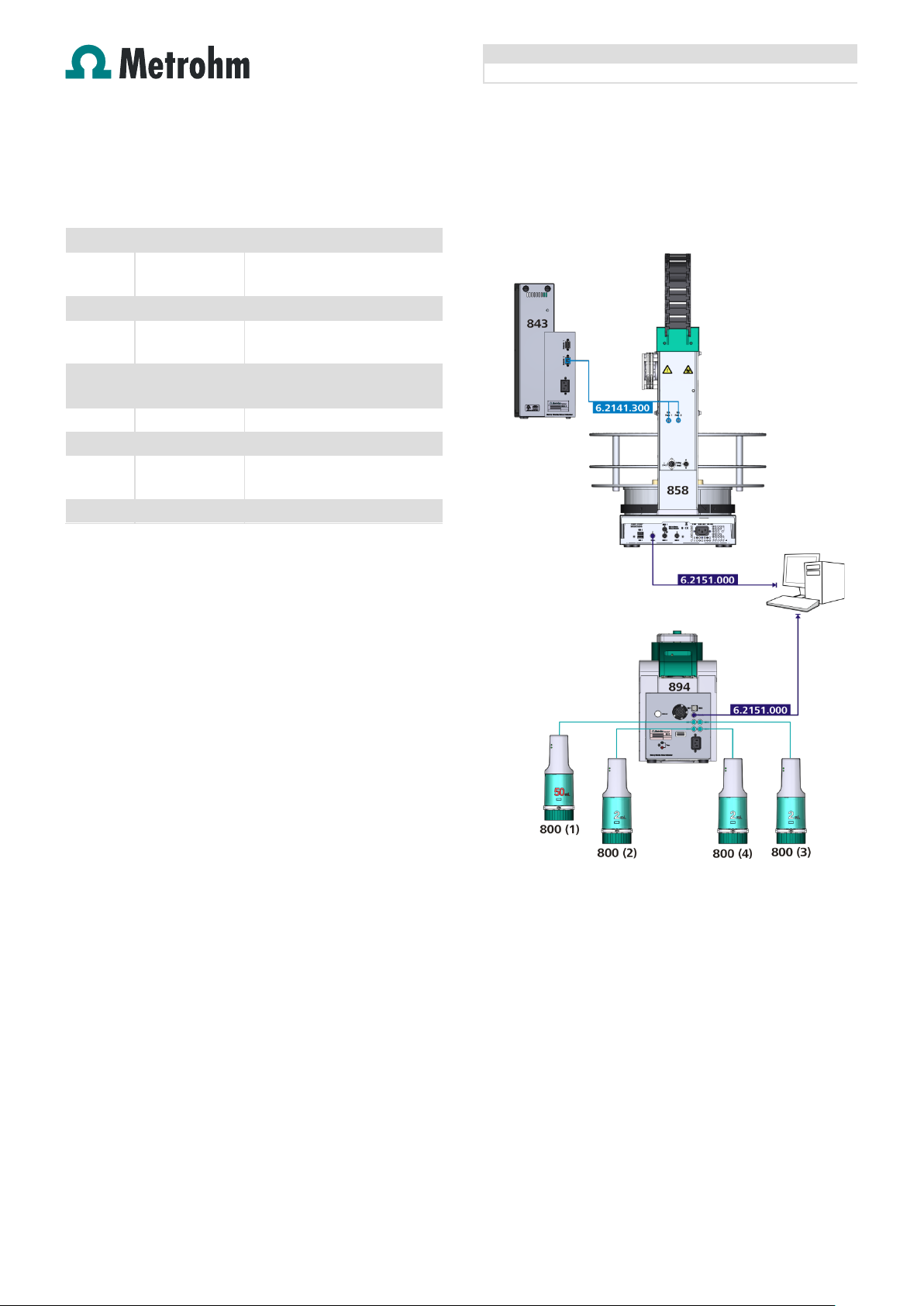
Fig 2 Electrical connections
Please note! The cable 6.2141.300 has to be connected to
«Remote 2» of the 843 Pump Station.
Page 3
Application Bulletin 403/1 e
Installation instruction for MVA-21
2.2. Tubing connections for rinsing and draining of
the measuring vessel
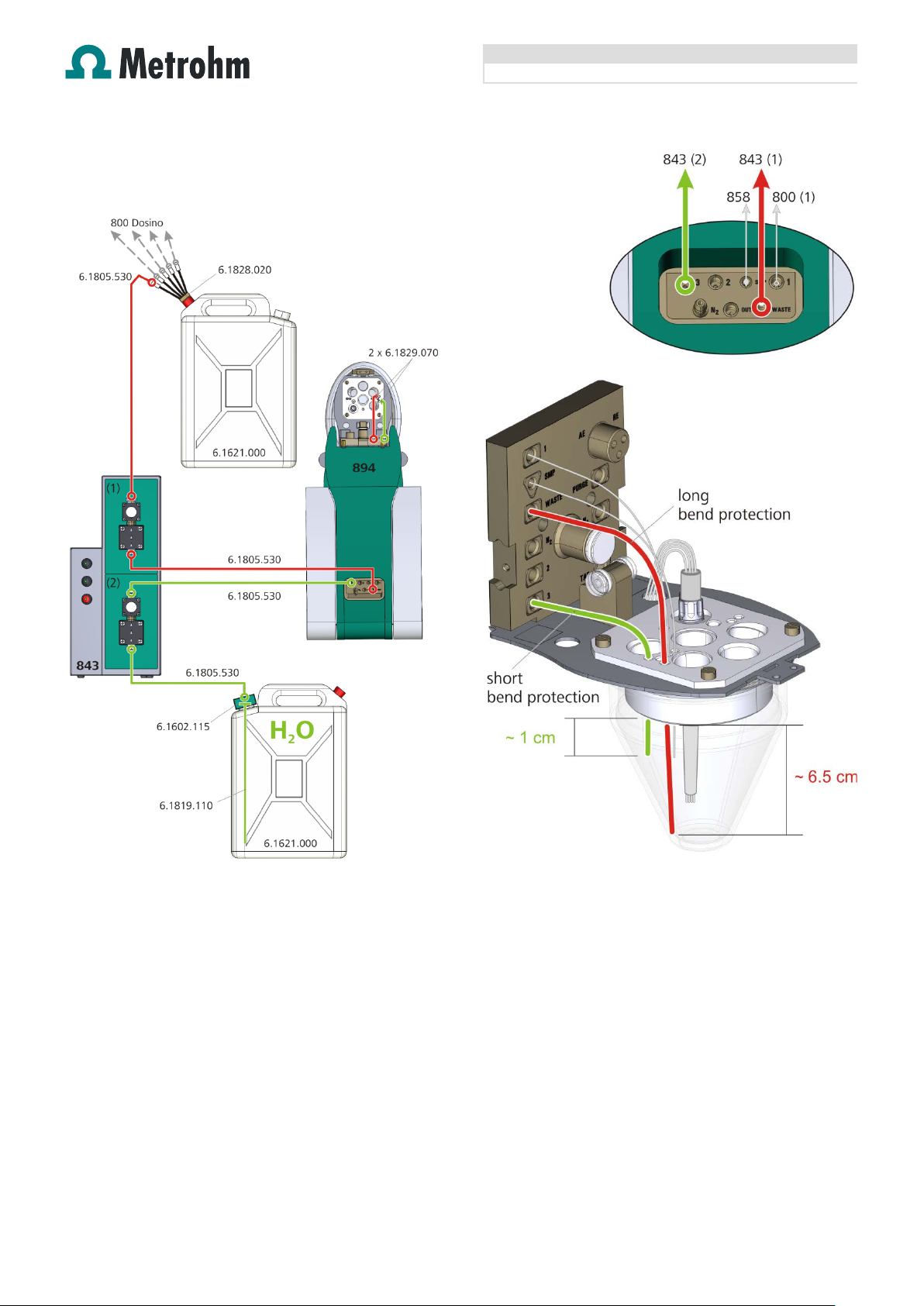
Fig 3: Tubing connections for rinsing and draining of the measuring
vessel
Page 3 of 12
Fig 4: Detailed view of the measuring head
Page 4
Application Bulletin 403/1 e
Installation instruction for MVA-21
2.3. Tubing connections for automatic dosing of
standard solutions and auxiliary solutions
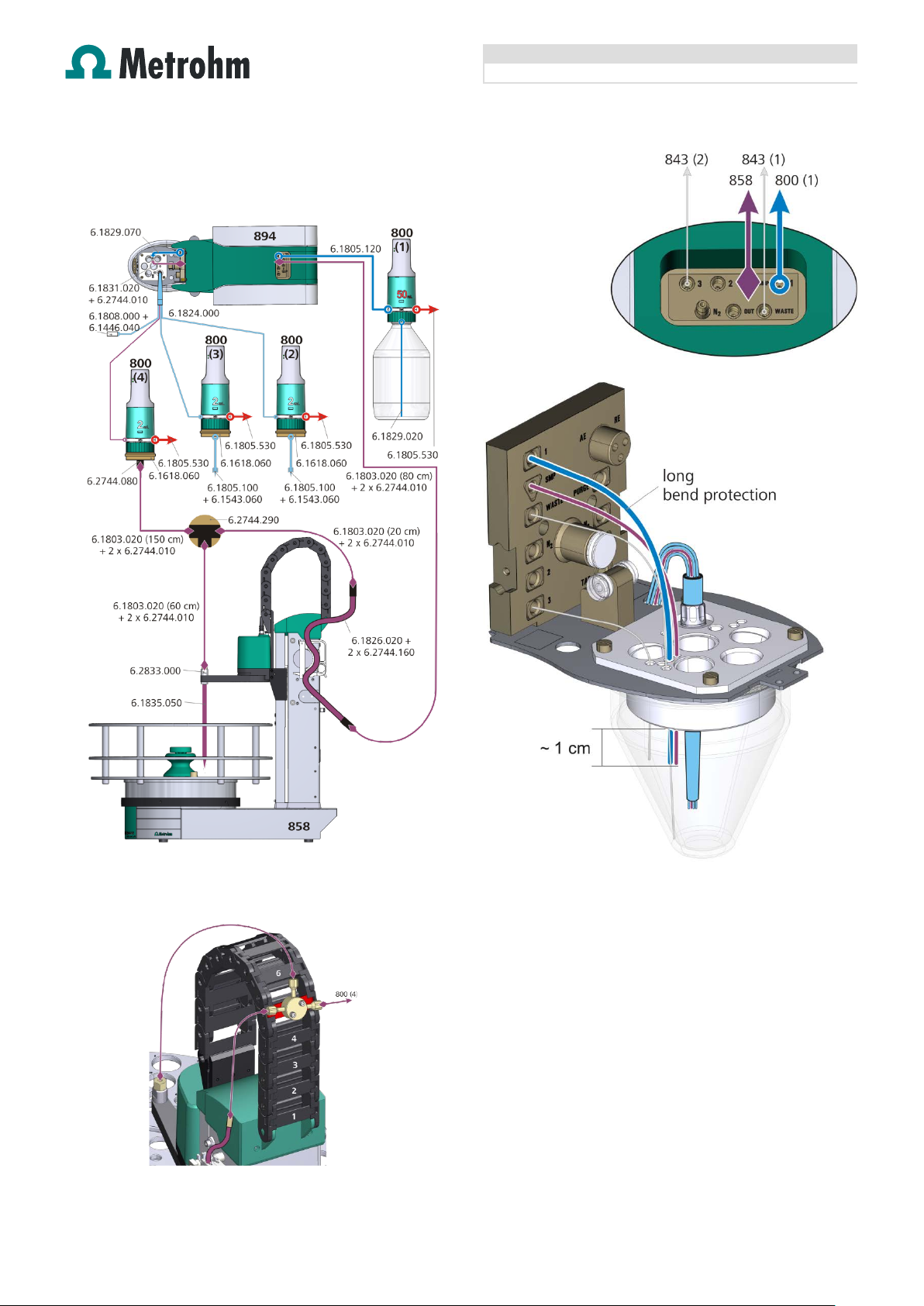
Fig 5: Tubing connections for automatic dosing of standard
solutions and auxiliary solutions
Fig 7: Detailed view of the measuring head
Fig 6: Detailed view to mount the T-connector
Page 4 of 12
Page 5

Application Bulletin 403/1 e
Installation instruction for MVA-21
8.103.8010xx
viva Tutorial CVS
referred to as Tutorial
Sensor name
Sensor type
Auxiliary electrode
Auxiliary electrode
RDE
RDE
Reference electrode
Reference electrode
3. viva Configuration
In addition to this application bulletin it is recommended to
have the following document availabl e.
Fig 8: Detailed view for the tubing connections of the dosing unit
waste port
3.1. Devices – 894 Professional CVS
The 894 Professional CVS is automatically recognized by
the viva software. When an instrument is connected for the
first time it needs to be entered in the viva «Configuration».
The corresponding dialogue will pop up automatically.
Device name* 894_1
* as used in the example method
For a step by step description please see the Tutorial
chapter «4.1.1 Configuring the instrument».
3.2. Sensors/Electrodes
With the software a set of electrodes is preinstalled in the
viva «Configuration». The following three electrodes have to
be present if the measuring command in the method is used
as specified in the viva method templates.
In the following chapters it will be
Page 5 of 12
3.3. Dosing units
An 807 Dosing Unit attached to an 800 Dosino which is
connected to the 894 Professional CVS is automatically
recognized by the viva software. When the Dosing Unit is
connected for the first time it needs to be entered in the viva
«Configuration». The corresponding dialogue will pop up
automatically. For a step by step description please see the
Tutorial chapter «5.1.3 Configuring dosing units».
3.3.1. Dosing unit at 800 Dosino (1)
Dosing Unit name as used in the viva method templates.
800 Dosino (MSB 1) 894/D1 50mL VMS
Parameters for preparation
Dosing port Prep/empty Dosing port 2
Page 6

Application Bulletin 403/1 e
Installation instruction for MVA-21
Port
Length
Diameter
Dosing port 1
Port 1
138 cm
2 mm
Dosing port 2
Port 3
0 cm
2 mm
800 Dosino (MSB 2)
894/D2 2mL Brightener
800 Dosino (MSB 3)
894/D3 2mL Suppressor
Dosing rate Fill port
Maximum
mL/L
Dosing rate special port
Maximum
mL/L
Port
Length
Diameter
Rotating direction
automatic
800 Dosino (MSB 4)
894/D4 2mL Std or sample
Dosing rate Fill port
4.0
mL/L
Dosing rate special port
maximum
mL/L
Fill port
Port 2
230 cm
1 mm
Special port
Port 4
0 cm
2 mm
Rotating direction
automatic
Solution name
Dosing Unit
Suppressor concentrate
894/D3 2mL Suppressor
Std or sample
894/D4 2mL Std or sample
Device name*
858 Professional Sample Processor 1
Axial distance
166.0
mm
Dosing rate port 1 Maximum mL/L
Dosing rate port 2 Maximum mL/L
Dosing rate Fill port Maximum mL/L
Dosing rate special port Maximum mL/L
Tubing parameters
Fill port Port 2 25 cm 2 mm
Special port Port 4 0 cm 2 mm
Valve disk
Rotating direction automatic
3.3.2. Dosing unit at 800 Dosino (2) and 800 Dosino (3)
Dosing Unit name as used in the viva method templates.
Parameters for preparation
Dosing port Prep/empty Dosing port 2
Dosing rate port 1 2.0 mL/L
Dosing rate port 2 maximum mL/L
Tubing parameters
Dosing port 1 Port 1 80 cm 0.3 mm
Dosing port 2 Port 3 0 cm 2 mm
Fill port Port 2 55 cm 2 mm
Special port Port 4 0 cm 2 mm
Valve disk
Tubing parameters
Port Length Diameter
Dosing port 1 Port 1 80 cm 0.3 mm
Dosing port 2 Port 3 0 cm 2 mm
Valve disk
3.4. Solutions
Solutions that should automatically be dosed have to be
defined in the viva «Configuration» and need to be
assigned to the Dosing Unit which is used for the dosing.
The following table shows the solution names and assigned
Dosing Units as used in the viva method templates.
VMS 894/D1 50mL VMS
Brightener concentrate 894/D2 2mL Brightener
SOLUTION TYPE for «VMS» and «Suppressor concentrate»
has to be AUXILIARY SOLUTION, for «Brightener concentrate»
and «Std or sample» it is S
TANDARD SOLUTION.
For a step by step description please see the Tutorial
chapter «5.1.4 Define solutions».
3.5. Devices – 858 Professional Sample Processor for CVS
The «858 Professional Sample Processor for CVS» is
automatically recognized by the viva software. When an
instrument is connected for the first time it needs to be
entered in the viva «Configuration». The corresponding
dialogue will pop up automatically.
3.3.3. Dosing unit at 800 Dosino (4)
Dosing Unit name as used in the viva method templates.
Parameters for preparation
Dosing port Prep/empty Dosing port 2
Dosing rate port 1 2.0 mL/L
Dosing rate port 2 maximum mL/L
Page 6 of 12
* as used in the example method
For a step by step description please see the Tutorial
chapter «6.1.1 Configuring the instrument».
3.5.1. Tower
Tower parameters
Max. stroke path 130 mm
Min. beaker radius Off
Lift rate 25 mm/s mm/s
Page 7

Application Bulletin 403/1 e
Installation instruction for MVA-21
Rack name
6.2141.450
Shift rate
20
°/s
defined
Rinse position
0
mm
Shift position
0
mm
Rinse position
Not available
Shift position
Not available
Special position
Not available
Swing head
Swing position 0 mm
Rinse position 0 mm
External position Not used
3.5.2. Rack
3.5.3. Rack data Rack parameters
Beaker radius samples off mm
Beaker sensor off
Rack offset 0 °
Lift positions – Tower 1
Work position
User
mm
Special position 0 mm
Lift positions – Tower 2
Work position Not available
Special beakers
Not used
3.5.4. Needle adjustment
The work position of the pipetting needle 6.1835.050 has to
be adjusted in a way that the lower end of the needle is
positioned max. 1 mm above the bottom of the sample vial.
This is essential to guarantee a complete transfer of the
sample from the sample vial on the rack of the 858
Professional Sample Processor into the measuring vessel of
the 894 Professional CVS.
0.5 … 1 mm
Fig 9: Needle adjustment
Procedure to adjust the needle position in viva
1. Insert an empty sample vial to the desired sample
position on the rack (posit ion 5 7 to 126).
2. Click on the Manual symbol.
3. Select Tower 1 (Sample changers – 858 Professional
Sample Processor).
4. Open tab «Move».
5. Enter the position of the empty sample vial in the field
«Target position».
6. Click Start to move the needle to the chosen rack
position.
7. Enter 125 mm in the field «Target position» in the
section «Lift position».
8. Click Start to lower the needle to the chosen target
position. To adjust the needle like shown above, use
the arrow up and down buttons to lower the
needle stepwise.
Page 7 of 12
Page 8

Application Bulletin 403/1 e
Installation instruction for MVA-21
9. Once the needle is properly adjusted select the tab
«Assign position».
10. The new value can be seen in the section «Lift position
– Current position».
11. Select the option «Work position for Tower» in the
section Lift position.
12. Click on «Assign» in the section Lift position .
13. Leave the Manual control with a click on the «Close»
button.
4. viva «Method»
4.1. Method run
viva software includes three method templates for CVS
analysis with an automated system.
• Brightener determination (CVS, MLAT), automated
• Conditioning (Cu VMS), automated
• Suppressor determination (CVS, DT), automated
The templates already establish t h e bas ic s eq u e nc es fo r the
different applications, the use of 800 Dosinos for automatic
dosing as well as the calculation of the result and the
application of a sample changer and pumps to process a
sample series. However certain commands and settings
have to be adapted to the used hardware and the
requirements of the specific application.
For a step by step description please see the Tutorial
chapter «6.2 Methods for the automated determination».
The following commands have to be adapted:
4.1.1. Measuring commands
Such as
4.1.2. Dosing commands
Such as:
• Define the volume of solution that should be dosed
when this command is due.
Such as:
• Define the volume of solution that should be dosed
when this command is due.
• Assign the Dosing Unit that should be used to run this
command.
Such as:
• On the tab «General/Hardware» assign the 894
Professional CVS instrument to which the 800 Dosino is
connected.
4.1.3. Automation commands
Such as:
• Assign the 858 Professional Sample Processor that
should be used to run this command.
4.1.4. Transferring sample
This only applies for the brightener determination by MLAT!
To guarantee a complete transfer of the sample from the
sample vial on the rack of the 858 Professional Sample
Processor into the measuring vessel of the 894 Professional
CVS the peristaltic pump time has to be adjusted in
the TRACK
– PERISTALTIC PUMP in the command PUMP –
PERISTALTIC PUMP ON.
• Assign the 894 Professional CVS instrument to be used
on the tab «General/Hardware».
• Adapt the measuring parameters on the tabs «Pre-
treatment», «Sweep», «Post-treatment» and
«Potentiostat» according to the requirements of the
application. These parameters can be found in separate
application documentation.
Page 8 of 12
Fig 10: Method snippet TRACK – PERISTALTIC PUMP
Page 9

Application Bulletin 403/1 e
Installation instruction for MVA-21
Cell volume
50 mL
100 mL
4.1.5. Rinsing measuring vessel
After each sample the measuring vessel need to be rinsed
with deionized water. The rinsing and draining times depend
on the total volume used in the determination.
If the method templates are used, the rinsing and draining
times are defined in the corresponding PUMP
commands in
the TRACK –RINSE and TRACK – DRAIN. The number of
rinsing cycles is defined in the command LOOP – LOOP
RINSING in the TRACK – RINSING CYCLES.
Fig 11: Method snippet TRACK – RINSING CYCLE
Examples for rinsing and draining times:
Number of rinsing cycles 2 2
Draining time [s] 35 50
Rinsing time [s] 9 18
Please note! The device assigned to the commands PUMP
– PUMP RINSE und PUPM – PUMP DRAIN need to be the
858 Professional Sample Processor, since the 843 Pump
Station is connected to and controlled from the sample
changer.
4.1.6. Rinsing transfer tubing
This only applies for the brightener determination by MLAT!
After each sample the transfer tubing from the 858
Professional Sample Processor to the measuring vessel of
the 894 Profess ional CVS nee d to be rinse d with deioni zed
water. The rinsing solution is placed in a vial on the rack of
the 858 Professional Sample Processor. The position of the
rinsing solution relative to the sample position is defined in
the TRACK
command MOVE
– GO TO RINSING POSITION in the
– MOVE RINSING POSITION.
Fig 12: Method snippet TRACK – GO TO RINSING POSITION
The position of the rinsing solution is defined as «sa mple
position + 28». This means the outer circle on the rack
6.2041.450 is used for the sample the inner circle for the
rinsing solution
The transfer time for the rinsing solution corresponds to the
sample transfer time defined in the TRACK
PUMP
in the command PUMP – PERISTALTIC PUMP ON.
– PERISTALTIC
4.2. Evaluation
Settings regarding evaluation and documentation of the
determination are located in the «Evaluation» part of the
method. The templates already include all necessary
settings to determine brightener or suppressor concentration
in an acid copper bath. If modifications however should be
necessary, here is where important parameters are found:
4.2.1. Substances
In the «Substances» part settings for peak recognition and
baseline parameters are defined.
4.2.2. Standards
In the «Standards» part the concentration of the used
standard solution is defined.
4.2.3. Calibration
In the «Calibration» part the calibration method, such as DT
or MLAT, is defined as well as the regression type.
Page 9 of 12
Page 10

Application Bulletin 403/1 e
Installation instruction for MVA-21
4.2.4. Results
In the «Results» part on the tab «Results» the substance is
selected for which the concentration should be calculated
and displayed.
5. Operation
5.1. Suppressor determination series
5.1.1. Manual operation
• Dosing Unit «894/D1 50mL VMS» connected to Dosino
1 has to be prepared with VMS.
• Suppressor standard solutions and plating bath
samples are placed on position 57 to 111 of the sample
rack using the sample vials for 11 mL (6.2743.057).
• On the position after the last sample a vial with pure
water is placed to rinse Dosino 4 after the end of the
suppressor sample series.
5.1.2. Workplace
• In the «Run» window on the tab «Determination series»
create a sample table
Fig 14: Example sample table for suppressor determination
• To run a calibration with a standard solution select
sample type STANDARD. For a determination the sample
type S
AMPLE has to be selected.
• No «Sample amount» needs to be defined in the
sample table, since addition volumes for the standard
and the sample are defined in the method
commands ADD
STD and ADD SAMPLE DT.
Fig 13: Example positions of solutions on the sample rack
6.2041.450 for suppressor determination
5.1.3. Course of events
• The execution of calibration and determination by
dilution titration is controlled by the 894 Professional
CVS and viva.
a) T he measurin g ves sel is empti ed using the 843
Pump Station.
b) Dosing Unit «894/D4 2mL Std or sample»
connected to Dosino 4 is automatically rinsed and
prepared with suppressor standard or sample from
the vial on the rack of the sample changer.
c) The measuring vessel is rinsed using the 843
Pump Station.
d) Dosino 1 automatically adds the VMS and Dosino
4 is used for the automatic addition of suppressor
standard or plating bath sample.
e) At the end of each determination the measuring
vessel, is automatically emptied and rinsed using
the 843 Pump Station.
Next sample starts again from a).
• Recalibration within a determination series is possible.
• At the end of a determination series Dosino 4 is
automatically prepared with rinsing solution.
Page 10 of 12
Page 11

Application Bulletin 403/1 e
Installation instruction for MVA-21
5.2. Brightener determination series
5.2.1. Manual operation
• Dosing Unit «894/D1 50mL VMS» connected to Dosino
1 has to be prepared with VMS.
• Dosing Unit «894/D2 2mL Brightener» connected to
Dosino 2 has to be prepared with brightener
concentrate.
• Dosing Unit «894/D3 2mL Suppres sor» con nec ted to
Dosino 3 has to be prepared with suppressor
concentrate.
• Plating bath samples are placed on position 1 to 28 of
the sample rack using the sample vials for 50 mL
(6.2747.010). ). The exact sample volume needed for
the determination has to be pipetted into the vial.
• Rinsing solutions are placed on position 29 to 56 of the
sample rack using the sample vials for 50 mL
(6.2747.010). Usually the same volume of distilled
water is used for rinsing like it was used for the sample.
The rinsing solution has to be placed on the inner circle
on the neighboring position of the sample (Sample
position + 28).
5.2.2. Workplace
• In the «Run» window on the tab «Determination series»
create a sample table
Fig 16: Example sample table
• As sample type SAMPLE has to be selected.
• For «Sample amount» the volume pipetted into the vial
has to be entered.
5.2.3. Course of events
• The execution the determination by modified linear
approximation technique is controlled by the 894
Professional CVS and viva.
a) T he measurin g ves sel is empti ed using the 843
Pump Station.
b) The intercept solution is automatically prepared at
the beginning of each determination, by dosing
VMS from Dosino 1 and suppressor concentrate
from Dosino 3.
c) After the determination of the intercept value, the
plating bath sample is transferred from the sample
rack to the measuring vessel by means of the
build-in peristaltic pump of the 858 Profes sional
Sample Processor. The sample is added on top of
the intercept solution.
d) Standard addition is carried out automatically with
brightener concentrate from Dosino 2.
e) At the end of each determination the measur ing
vessel is emptied using the 843 Pump Station.
f) The transfer tubing from the sample changer to the
measuring vessel is rinsed with the rinsing solution
placed on the rack of the sample changer.
g) After the transfer tubing is rinsed the measuring
vessel is automatically emptied and rinsed using
the 843 Pump Station.
Next sample starts again from a).
Fig 15: Example positions of solutions on the sample rack
6.2041.450
Page 11 of 12
Page 12

Application Bulletin 403/1 e
Installation instruction for MVA-21
6. Remarks
6.1. Single additive setup
If the system is only used for suppressor or brightener
determination the unused port at the T connector
(6.2744.290) has to be closed with a threaded stopper
(6.2744.060).
6.2. Combination of applications
The determination of suppressor by dilution titration (DT)
and the determination of brightener by modified linear
approximation technique (MLAT) can also be combined in
one series.
6.3. Storing dosing units
When the dosing units are not used (during the night, over
the weekend) the dosing cylinder has to be rinsed with
water. Otherwise elemental copper can be formed or
additives can precipitate between the valve disk and the
distributor disk or in the tubings. A blockage can damage
the 800 Dosino. Emptying the cylinder and filling it with
water is sufficient to prevent a blockage.
6.4. Storing electrodes
When the electrodes are not used (during the night, over the
weekend) the electrodes should be thoroughly rinsed.
Working and auxiliary electrode can either be stored in
deionized water or dry. The reference electrode should be
stored separately in a vial filled with deionized water (KCl
solution, in case KCl is used as bridge electrolyte), so that
the reference electrode immerses at least to the rim of the
electrolyte vessel.
6.5. Waste container
The waste container must not be closed completely. For
pressure balancing in the waste container, keep at least one
opening unsealed. Overpressure would lead to a
malfunction of the drain pump.
Page 12 of 12
 Loading...