

Page 1
CH-9101 Herisau/Switzerland
Phone ++41 71 353 85 85
Fax ++41 71 353 89 01
CompuServe 100031,3703
Internet http://www.metrohm.com
E-Mail sales@metrohm.ch
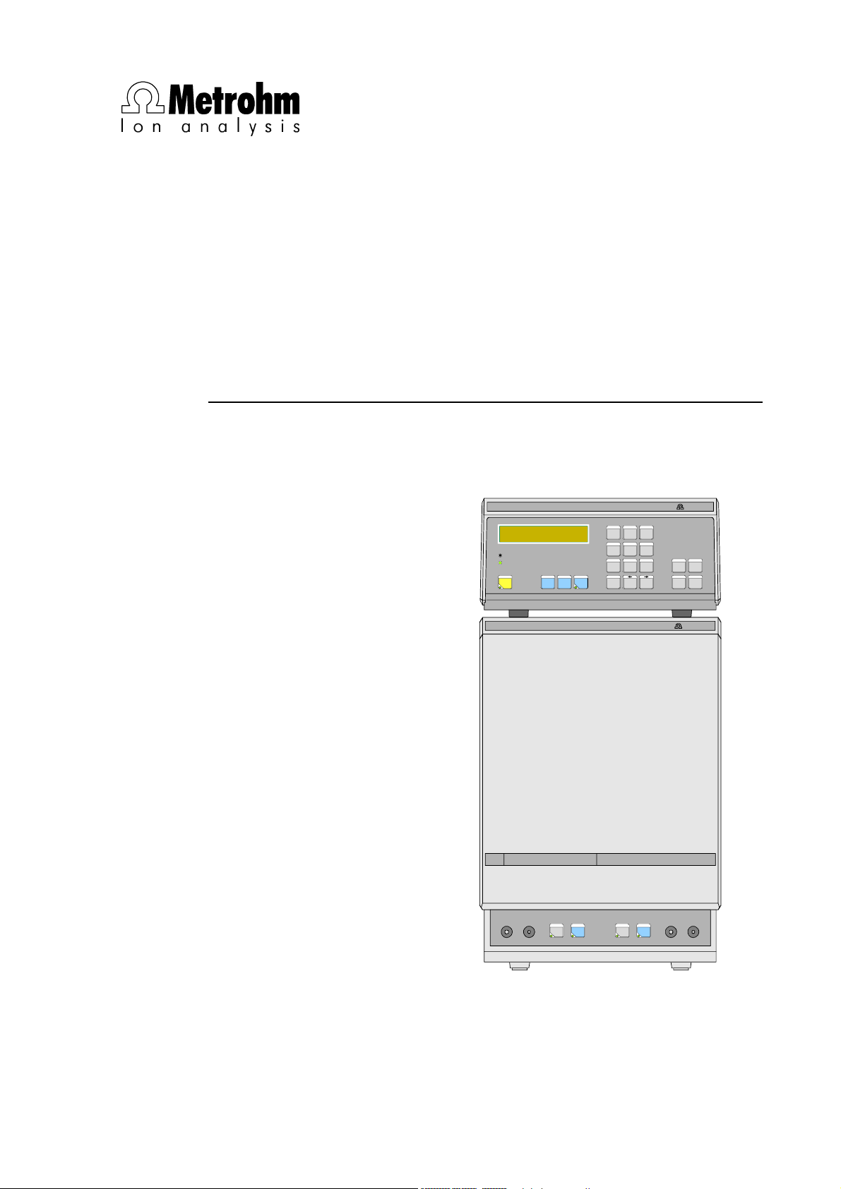
732 IC Detector
733 IC Separation Center
5.732.0012 Program
IC Detector732
+0.023 µS/cm 15.2 min
Full Scale 5.00 µS/cm
OVERLOAD
THERMOSTAT
FULL
PARAM
SCALE
IC Separation Center733
MetrohmMetrohm
METHOD
PUMP R/S
CONFIG
7
8 9
CONFIG
EVENT
PROGRAM
ZERO OFF
4
5 6
PRINT
REPORT
PLOT
1
2 3
MARK
PROG
R/S
0
.
SELECT CLEAR
QUIT ENTERZERO
-
/+
MetrohmMetrohm
FILL INJECT
A B
STEP
FILL INJECT
8.732.1033 Instructions for Use
1.10.1998 / dö
Page 2

Table of contents
Table of contents
1 Introduction............................................................................................1
1.1 Instrument description.............................................................................1
1.2 Parts and controls..................................................................................... 3
1.2.1 732 IC Detector .............................................................................3
1.2.2 733 IC Separation Center..............................................................5
1.3 Information on the Instructions for Use................................................8
1.3.1 Organization .................................................................................. 8
1.3.2 Notation and pictograms............................................................... 9
1.4 Safety notes .............................................................................................10
1.4.1 Electrical safety............................................................................10
1.4.2 General precautionary rules........................................................10
2 Installation ...........................................................................................11
2.1 Flow chart.................................................................................................11
2.2 Setting up the instruments....................................................................12
2.2.1 Packaging....................................................................................12
2.2.2 Check ..........................................................................................12
2.2.3 Location.......................................................................................12
2.2.4 Arrangement of the instruments..................................................12
2.3 Connection of 733 IC Separation Center.............................................13
2.3.1 733.0010/733.0X30 IC Separation Center................................... 13
2.3.2 733.0X20 IC Separation Center................................................... 14
2.3.3 Connection of syringe and suction tubing.................................. 16
2.3.4 Connection of the drain tube....................................................... 16
2.3.5 Connection of the 6.5324.000 Bottle rack (option) ..................... 16
2.4 Mains connection....................................................................................17
2.4.1 Setting the mains voltage............................................................ 17
2.4.2 Fuses........................................................................................... 18
2.4.3 Mains cable and mains connection ............................................18
2.4.4 On/off switching of the instruments ............................................18
2.5 Capillary connections.............................................................................19
2.5.1 Capillaries.................................................................................... 19
2.5.2 Steel connectors.......................................................................... 19
2.5.3 PEEK connectors ........................................................................20
2.6 Connection of 709 IC Pump...................................................................21
2.6.1 Electrical connection ................................................................... 21
2.6.2 Pulsation dampener .................................................................... 21
2.6.3 Filter unit PEEK............................................................................ 22
2.6.4 Filter unit Manufit ......................................................................... 23
2.6.5 Connection to injection valve with PEEK capillaries ...................24
2.6.6 Connection to injection valve with steel capillaries..................... 25
2.6.7 Passivation of the IC system.......................................................27
2.7 Precolumns..............................................................................................28
2.7.1 General information on precolumns............................................28
2.7.2 Precolumns with twin cartridge holder........................................28
2.7.3 Precolumns with cartridge head .................................................30
2.7.4 IC anion precolumn SUPERSEP ................................................. 31
732 IC Detector / 733 IC Separation Center
I
Page 3

Table of contents
3 Operating tutorial ........................................................................45
2.8 Separating columns and suppressor module.................................... 32
2.8.1 General information on separating columns .............................. 32
2.8.2 Selection of the sample loop ...................................................... 32
2.8.3 General information on suppressor module............................... 33
2.8.4 One-channel system without suppressor module...................... 35
2.8.5 Two-channel system without suppressor module...................... 35
2.8.6 One-channel system with suppressor module........................... 37
2.8.7 Leak testing and conditioning..................................................... 40
2.9 Connection of external devices............................................................ 41
2.9.1 Connection of a recorder ............................................................ 41
2.9.2 Connection of «IC Metrodata for Win95».................................... 41
2.9.3 Connection of the 750 Autosampler ........................................... 41
2.9.4 Connection of the 766 IC Sample Processor ............................. 41
2.9.5 Connection of the 791 VA Detector ............................................ 41
2.9.6 Connection of a printer ............................................................... 42
2.9.7 Connection of a PC..................................................................... 44
2.9.8 Connection of devices to the remote interface........................... 44
3.1 Requirements ..........................................................................................45
3.2 Preparations............................................................................................. 46
3.3 Putting into operation............................................................................ 48
3.4 Calibration................................................................................................ 59
3.5 Sample determination............................................................................ 62
3.6 Storing as a method............................................................................... 64
4 Operation ...............................................................................................67
4.1 Operating sequences............................................................................. 67
4.1.1 General flow chart ....................................................................... 67
4.1.2 Flow chart for basic settings....................................................... 68
4.1.3 Flow chart for putting into operation ........................................... 69
4.1.4 Flow chart for injection ................................................................ 70
4.2 Fundamentals of the operation ............................................................ 71
4.2.1 Display......................................................................................... 71
4.2.2 Overview of key functions ........................................................... 72
4.2.3 Instrument dialog ........................................................................ 77
4.2.4 Data entry.................................................................................... 79
4.2.5 Text entry..................................................................................... 80
4.3 Displays in the standby mode.............................................................. 81
4.3.1 Measured value and current time ............................................... 81
4.3.2 Status messages ........................................................................ 82
4.4 Basic settings.......................................................................................... 84
4.4.1 Setup........................................................................................... 84
4.4.2 Configuration, <CONFIG> key.................................................. 88
4.5 Measurement parameters...................................................................... 97
4.5.1 <PARAM> key ........................................................................... 97
4.5.2 <FULL SCALE> key................................................................. 102
II
732 IC Detector / 733 IC Separation Center
Page 4

Table of contents
4.6 Triggering of functions ........................................................................103
4.6.1 <FILL> keys .............................................................................103
4.6.2 <INJECT> keys........................................................................104
4.6.3 <ZERO> key ............................................................................ 105
4.6.4 <ZERO OFF> key ...................................................................106
4.6.5 <MARK> key............................................................................ 106
4.6.6 <PUMP R/S> key.....................................................................106
4.7 Programming .........................................................................................107
4.7.1 <PROGRAM> key.................................................................... 107
4.7.2 <PROG R/S> key..................................................................... 114
4.7.3 <EVENT> key........................................................................... 114
4.7.4 <METHOD> key ......................................................................117
4.8 Data output.............................................................................................119
4.8.1 <PRINT> key............................................................................ 119
4.8.2 <PLOT> key.............................................................................122
4.8.3 <REPORT> key........................................................................ 124
4.9 Examples of methods...........................................................................126
4.9.1 Cation determination with Metrosep Cation 1-2........................126
4.9.2 Anion determination with Metrosep Anion Dual 2.....................129
5 Notes – Maintenance – Faults ................................... 133
5.1 Practical notes on ion chromatography............................................133
5.1.1 Separating columns ..................................................................133
5.1.2 Pumps .......................................................................................134
5.1.3 Eluents.......................................................................................135
5.1.4 Suppressor module...................................................................136
5.1.5 Connections .............................................................................. 136
5.2 Maintenance and servicing..................................................................136
5.2.1 General information................................................................... 136
5.2.2 Passivation ................................................................................137
5.2.3 Recycling................................................................................... 137
5.2.4 Shutdown...................................................................................137
5.2.5 Changing separating columns..................................................138
5.2.6 Regeneration of the suppressor................................................140
5.2.7 Cleaning the suppressor........................................................... 141
5.2.8 Replacing the suppressor......................................................... 143
5.3 Faults and malfunctions ......................................................................145
5.3.1 Error messages .........................................................................145
5.3.2 Malfunctions and their rectification ...........................................148
5.4 Diagnostic tests.....................................................................................149
5.4.1 General...................................................................................... 149
5.4.2 Preparing instruments ............................................................... 150
5.4.3 Checking working memory (RAM) ............................................ 151
5.4.4 Check keypad ...........................................................................151
5.4.5 Check display............................................................................152
5.4.6 Check RS232 interface.............................................................. 153
5.4.7 Check remote interface.............................................................154
5.4.8 Internal hardware test................................................................ 155
5.4.9 Initialize data memory................................................................157
5.5 Validation / GLP.....................................................................................159
732 IC Detector / 733 IC Separation Center
III
Page 5

Table of contents
6 Interfaces .......................................................................................... 161
6.1 RS232 interfaces................................................................................... 161
6.1.1 General rules for remote control ............................................... 161
6.1.2 Call-up of objects...................................................................... 162
6.1.3 Triggers .....................................................................................163
6.1.4 Status messages ...................................................................... 164
6.1.5 Error messages......................................................................... 165
6.1.6 Remote control commands ...................................................... 166
6.1.7 Data transmission protocol....................................................... 177
6.1.8 Handshake................................................................................ 178
6.1.9 Pin assignment.......................................................................... 181
6.1.10 RS232 error rectification............................................................ 182
6.2 Remote interfaces.................................................................................183
6.2.1 "Remote" interface..................................................................... 183
6.2.2 "733 IC Separation Center" interface......................................... 185
6.3 Analog output........................................................................................ 187
6.4 External power supply for 733 IC Separation Center......................187
6.5 Valve interfaces..................................................................................... 188
7 Appendix ............................................................................................. 189
7.1 Technical data ....................................................................................... 189
7.1.1 732 IC Detector ......................................................................... 189
7.1.2 733 IC Separation Center.......................................................... 192
7.2 Standard equipment............................................................................. 193
7.2.1 732 IC Detector ......................................................................... 193
7.2.2 733 IC Separation Center.......................................................... 194
7.3 Optional accessories............................................................................ 196
7.3.1 Accessories for 733 IC Separation Center................................ 196
7.3.2 Separating columns and precolumns....................................... 198
7.3.3 Additional devices and cables.................................................. 202
7.4 Warranty and conformity.....................................................................204
7.4.1 Warranty .................................................................................... 204
7.4.2 EU Declaration of conformity .................................................... 205
7.4.3 Certificate of conformity and system validation........................ 207
7.5 Index........................................................................................................ 209
IV
732 IC Detector / 733 IC Separation Center
Page 6

Table of contents
List of figures
Fig. 1: Block diagram of the ion chromatography system ........................................... 2
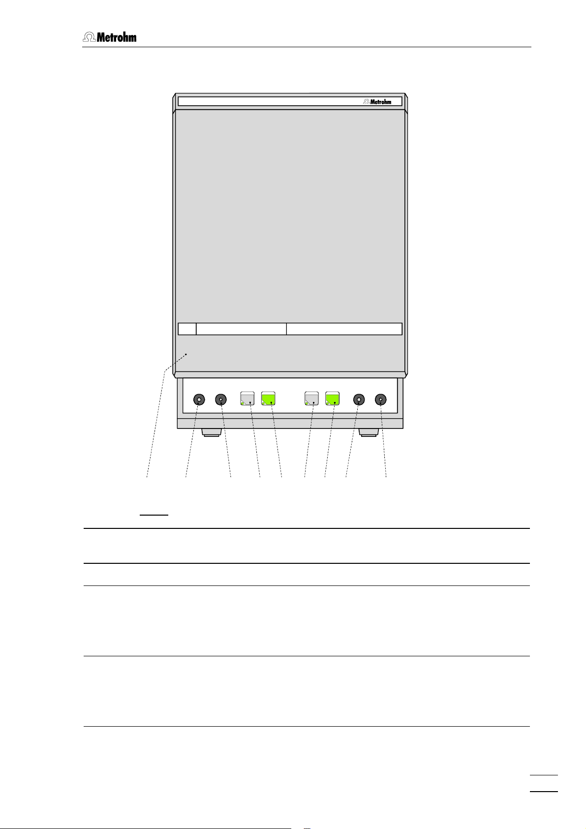
Fig. 2: Front of the 732 IC Detector .............................................................................. 3
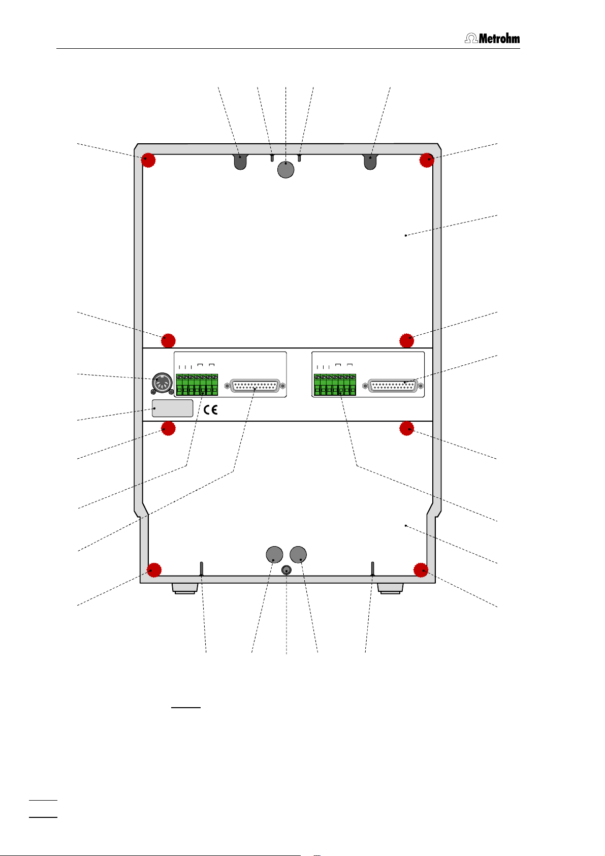
Fig. 3: Rear of the 732 IC Detector............................................................................... 4
Fig. 4: Front of the 733 IC Separation Center............................................................... 5
Fig. 5: Rear of the 733 IC Separation Center................................................................6
Fig. 6: Connection 732 – 2.733.0010/2.733.0X30 ...................................................... 13
Fig. 7: Connection 732 – 2.733.0X20 ......................................................................... 15
Fig. 8: Setting the mains voltage ................................................................................ 18
Fig. 9: Connectors for capillaries................................................................................ 20
Fig. 10: Connection of 709 IC Pump ............................................................................ 21
Fig. 11: 6.2821.100 Filter unit PEEK .............................................................................22
Fig. 12: 6.2821.000 Filter unit Manufit...........................................................................23
Fig. 13: Connection to injection valve with PEEK capillaries........................................25
Fig. 14: Connection to injection valve with steel capillaries .........................................26
Fig. 15: Installing precolumn cartridges ....................................................................... 29
Fig. 16: Interior of the 733.0010 IC Separation Center .................................................34
Fig. 17: Interior of the 733.0X30 IC Separation Center................................................. 36
Fig. 18: Connections at suppressor module................................................................38
Fig. 19: Ion chromatogram of the calibration ...............................................................61
Fig. 20: Ion chromatogram of the drinking water sample ............................................63
Fig. 21: Schematic representation of the instrument dialog......................................... 78
Fig. 22: Ion chromatogram for cation standard with Metrosep Cation 1-2 ................ 128
Fig. 23: Ion chromatogram for anion standard with Metrosep Anion Dual 2 ............. 131
Fig. 24: Assembling the suppressor........................................................................... 142
732 IC Detector / 733 IC Separation Center
V
Page 7

Table of contents
List of numbered parts and controls
11 Display ................................................3
22 Main function keys ..............................3
33 Numeric keys ......................................3
44 Auxiliary function keys.........................3
55 Program status display ....................... 3
66 Auto-zero display ............................... 3
77 Thermostat display.............................. 3
88 Overload display .................................3
99 Mains switch ..................................4,18
1010 Serial number......................................4
1111 Analog output 0…1 V.......................... 4
1212 Analog output 0…10 mV.....................4
1313 Connection for detector block ............4
1414 Connection for
733 IC Separation Center....................4
1515 Connection for 709 IC Pump ..............4
1616 RS232 interface...................................4
1717 Remote interface.................................4
1818 Mains connection plug...................4,18
1919 Fuse holder ....................................4,18
2020 Door to interior ....................................5
2121 Connection for syringe........................ 5
2222 Feedthrough for aspirating tubing ......5
2323 „FILL“ for valve A................................. 5
2424 „INJECT“ for valve A ...........................5
2525 „FILL“ for valve B.................................5
2626 „INJECT“ for valve B ...........................5
2727 Connection/Feedthrough....................5
2828 Feedthrough........................................5
2929 Opening for detector cable B .............6
3030 Opening for outlet capillary B .............6
3131 Rear panel opening.............................6
3232 Opening for outlet capillary A..............6
3333 Opening for detector cable A..............6
3434 Knurled screw .....................................6
3535 Detachable rear panel.........................6
3636 Connection for 732 IC Detector A.......6
3737 Knurled screw .....................................6
3838 Terminal block for valve A................... 6
3939 Detachable rear panel.........................6
4040 Opening for inlet capillary A................6
4141 Rear panel opening.............................6
4242 Connection for drain tube ...................6
4343 Rear panel opening........................6,36
4444 Opening for inlet capillary B................ 6
4545 Connection for 732 IC Detector B....... 6
4646 Terminal block for valve B...................6
4747 Model plate .........................................6
4848 Connection for external supply...........6
4949 Ferrule ..........................................20,29
5050 Pressure screw.............................20,29
5151 Capillary ............................................20
5252 Compression fitting...........................20
5353 Connector with filter ..........................22
5454 Housing for filter unit......................... 22
5555 Connector .........................................22
5656 Inlet capillary ................................23,26
5757 Manufit pressure screw................ 23,29
5858 Counterpart end................................23
5959 PTFE gasket................................. 23,29
6060 4 Steel meshes ............................23,29
6161 Steel mesh holding end.................... 23
6262 Manufit housing ...........................23,29
6363 Outlet capillary .............................23,26
6464 Filter unit PEEK .................................25
6565 PEEK capillary.........................25,34,36
6666 Pulsation dampener................25,34,36
6767 Column connection
capillary..............................25,29,34,36
6868 Injection valve..........................25,34,36
6969 Filter unit Manufit............................... 26
7070 Coupling............................................ 26
7171 Steel capillary.................................... 26
7272 Outlet capillary ..................................29
7373 2 Steel meshes .................................29
7474 Precolumn cartridge..........................29
7575 Inlet capillary .....................................29
7676 IC separating column..............29,34,36
7777 Manufit pressure screw..................... 29
7878 Steel spacer ...................................... 29
7979 Steel connector for ferrule................. 29
8080 Manufit housing ................................29
8181 Detector block.............................. 34,36
8282 Inlet capillary for detector block...34,36
8383 Mounting rail ................................34,36
8484 Column holder .............................34,36
8585 Capillary for syringe .....................34,36
8686 Sample loop.................................34,36
8787 Inlet capillary for injector .............. 34,36
8888 PTFE aspirating tubing.................34,36
8989 Suppressor inlet capillary
for eluent ...................................... 36,38
9090 Suppressor inlet capillary
for H2SO4......................................36,38
9191 Suppressor outlet capillary
for H2SO4......................................36,38
9292 Suppressor outlet capillary
for H2O .........................................36,38
9393 Suppressor inlet capillary
for H2O .........................................36,38
9494 Suppressor outlet capillary
for eluent ...................................... 36,38
9595 Suppressor module ..........................36
9696 Coupling............................................ 36
9797 Screw nut ........................................ 142
9898 Connection piece............................ 142
9999 Suppressor rotor .............................142
100100 Suppressor holder .......................... 142
VI
732 IC Detector / 733 IC Separation Center
Page 8

1 Introduction
1.1 Instrument description
The 732 IC Detector is a conductivity detector especially designed for
ion chromatography with an extensive operating range and high sensitivity for the recording of chromatograms with and without chemical
suppression. The associated thermostattable detector block is normally
installed in the 733 IC Separation Center, but can also be used as a
separate detector. The two following versions are available:
• 2.732.0010 IC Detector with standard detector block
• 2.732.0110 IC Detector with metal-free detector block
The 732 IC Detector is operated using the keypad with operator guidance via the two-line LCD. In addition to setting of the measurement
parameters, time programs can be generated which can be used to initiate a large number of instrument functions for each of the maximum
20 program steps. Further, the same functions can be executed at a
specific time with 4 programmable "events".
1.1 Instrument description
The 732 IC Detector is equipped with various interfaces for communication purposes. Recorders, integrators or the «IC Metrodata for
Win95» chromatography data system can be connected to the analog
output (1 V or 10 mV) for the plotting and evaluation of chromatograms.
The two RS232 interfaces are used for the connection of a 709 IC
Pump, a printer or a PC for remote control of the IC system. Finally,
programmable signals at a "remote" interface can be employed to control any external devices which, in turn, can start functions at the IC
system.
The 733 IC Separation Center is a thermally and electronically isolated wet part which accommodates injectors, columns, detectors,
suppressor module and pulsation dampener and is controlled by the
732 IC Detector. The following versions are available:
• 2.733.0010 IC wet part with 1 injector for a one-channel system
with electronic suppression
• 2.733.0020 IC wet part with 2 injectors for a two-channel system
with electronic suppression
• 2.733.0120 IC wet part with 2 injectors for a two-channel system
with electronic suppression, metal-free
• 2.733.0030 IC wet part with 1 injector and 1 Metrohm
Suppressor Module MSM for a one-channel system
with chemical suppression
• 2.733.0130 IC wet part with 1 injector and 1 Metrohm
732 IC Detector / 733 IC Separation Center
Suppressor Module MSM for a one-channel system
with chemical suppression, metal-free
1
Page 9
1 Introduction
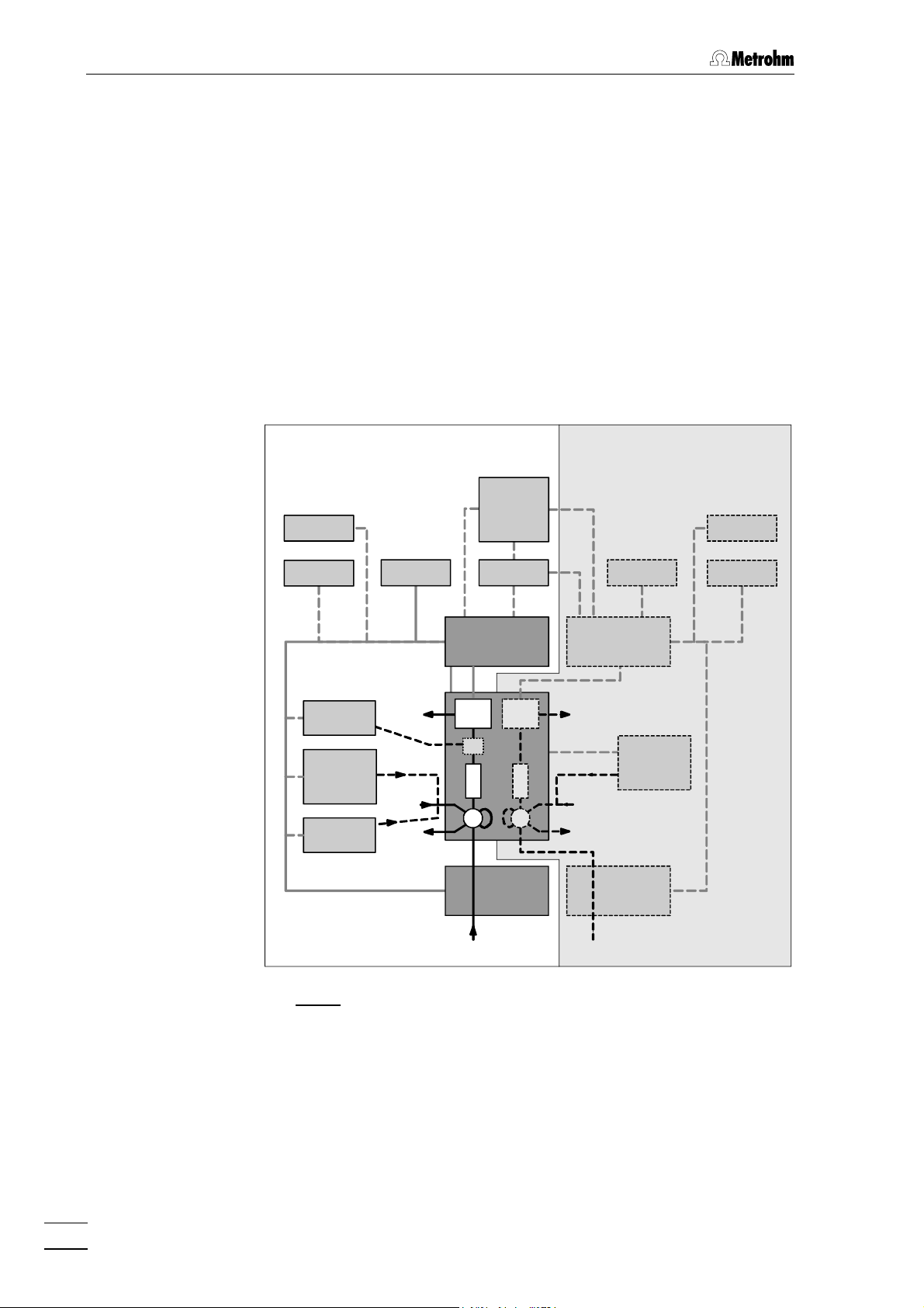
The 732 IC Detector and 733 IC Separation Center are the main components of a modular ion chromatography system that can be expanded to meet the wishes of the individual user (see Fig. 1). The
minimum configuration of the one-channel system also includes a 709
IC Pump, a separating column and a recorder. The two-channel system
requires at least a second 732 IC Detector and a second 709 IC Pump.
Printers, integrators, data recording devices, PC and autosamplers can
be attached to both systems. Further, practically all HPLC peripherals
and parts available on the market such as precolumns, additional
separating columns, additional detectors and other injection systems
can be seamlessly integrated in the system.
However, the individual IC units can also be freely combined with
common HPLC instruments. This offers the possibility of expanding
your system to a standalone ion chromatograph.
Two-channel systemOne-channel system
PC
IN IN
PL
752
750/766
S
754
W
IF
732
D
M
C
D
733
C
I
I
709 709
WW
S
W
PL
732
750/766
EE
Fig. 1: Block diagram of the ion chromatography system
PRPR
C Separating
column
D Detector PC PC 733 IC Separation Center
E Eluent PL Recorder 750 Autosampler
I Injector PR Printer 752 Pump Unit
IF Interface S Sample 754 Dialysis Unit
IN Integrator W Waste 766 IC Sample Processor
2
M
Suppressor module
(one-channel system only)
709
IC Pump
732
IC Detector
732 IC Detector / 733 IC Separation Center
Page 10
1.2 Parts and controls
1.2.1 732 IC Detector
88 11 22 33 44
IC Detector732
+0.023 µS/cm 15.2 min
Full Scale 5.00 µS/cm
OVERLOAD
THERMOSTAT
ZERO
PARAM
FULL
SCALE
PROG
R/S
CONFIG
7
ZERO OFF
4
PLOT
1
MARK
0
PUMP R/S
8 9
EVENT
5 6
REPORT
2 3
.
1.2 Parts and controls
METHOD
PROGRAM
PRINT
SELECT
-/+
QUIT ENTER
CLEAR
77 66 55
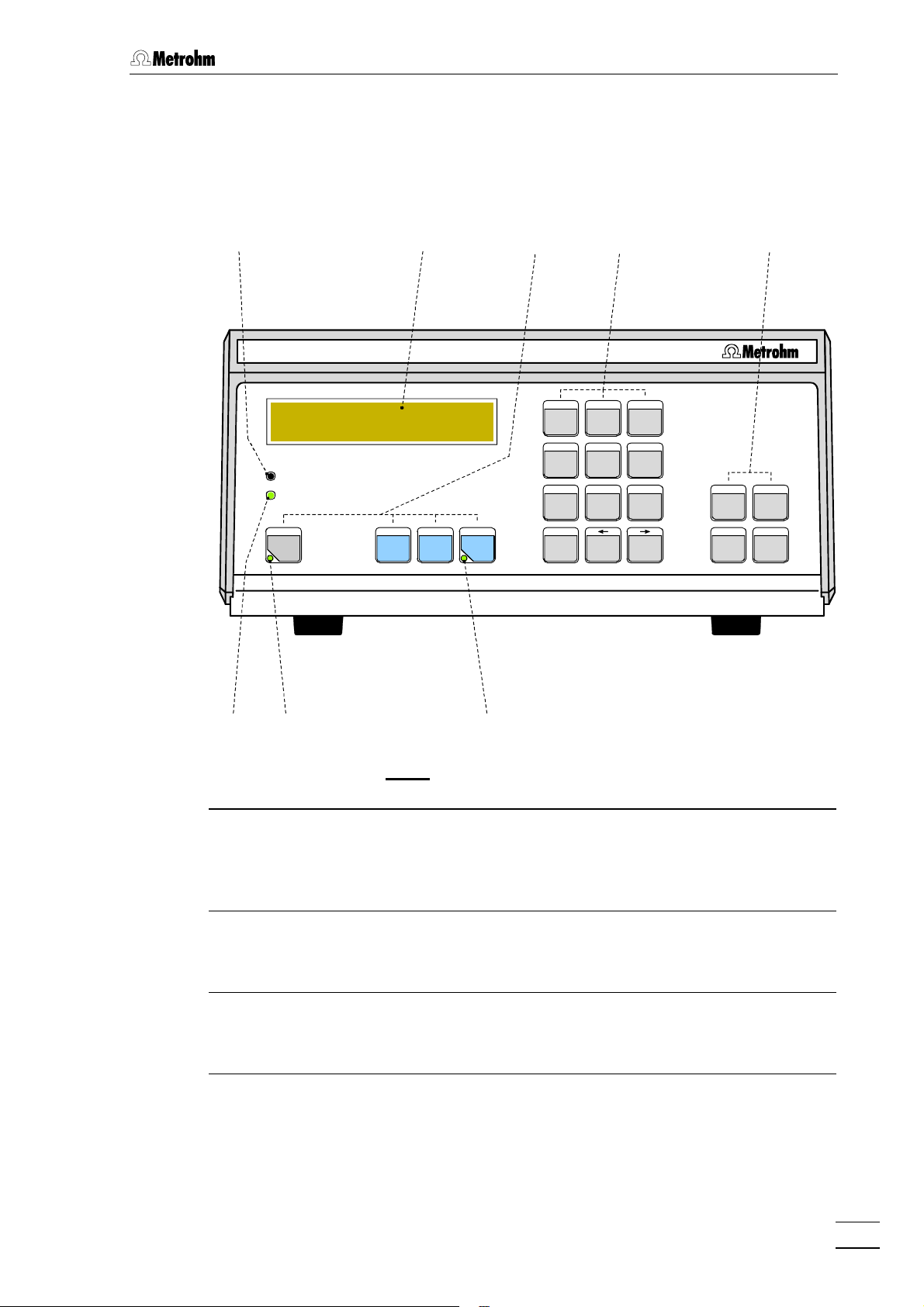
Fig. 2: Front of the 732 IC Detector
11 Display (LCD)
comprising 2 lines each of 24
characters
22 Main function keys
Auto-zero, Parameters, Full Scale,
Program start/stop
33 Numeric keys
Edit mode: Numeric keys
Basic mode: Function keys
44 Auxiliary function keys
Select, Clear, Quit, Enter
55 Program status display (LED)
LED dark: Program inactive
LED lit up: Program ready
LED flashes: Program running
66 Auto-zero display (LED)
LED dark: Auto-zero switched off
LED lit up: Auto-zero switched on
77 Thermostat display (LED)
LED dark: Heating switched off
LED lit up: Heating switched on
88 Overload display (LED)
LED lit up: Meas. signal >150%
of full-scale range
LED flashes: Meas. signal >180%
of full-scale range
732 IC Detector / 733 IC Separation Center
3
Page 11
1 Introduction
99
WARNING - Fire Hazard -
For continued protection replace only
with the same type and rating of fuse
Type 1.732.0010 Nr.
f=50-60 Hz
S=70 VA
100-120V:
220-240V:
S
Fuse
0,63A(T)
0,315A(T)
Output
0...1V 0...10mV
Remote
RS 232
Made by Metrohm Herisau Switzerland
1313121211111010
Detector Block
733 IC Separation Center
709 IC Pump
1919
1818 1717 1616 1515 1414
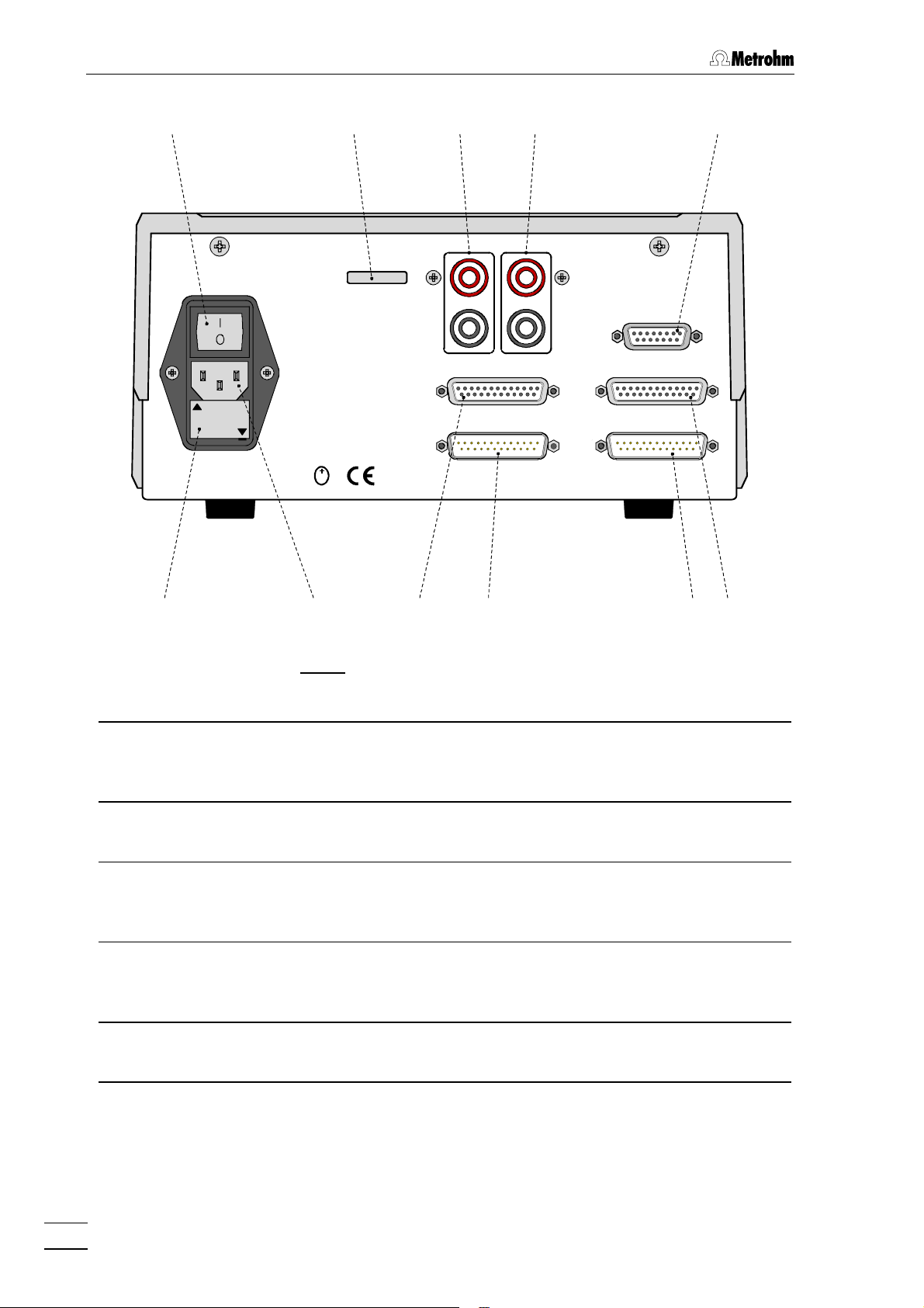
Fig. 3: Rear of the 732 IC Detector
99 Mains switch
switch to switch instrument on and off:
I = ON 0 = OFF
1515 Connection for 709 IC Pump
RS232 interface, can also be used for
connection of a printer
1010 Serial number 1616 RS232 interface
connection of a printer, PC, etc.
1111 Analog output 0……1 V
red socket: live
black socket: common
1212 Analog output 0……10 mV
red socket: live
1717 Remote interface
remote I/O lines for connection of
external devices
1818 Mains connection plug
mains connection, see section 2.4
black socket: common
1313 Connection for detector block 1919 Fuse holder
changing the fuses, see section 2.4
1414 Connection for 733 IC Separation
Center
4
732 IC Detector / 733 IC Separation Center
Page 12
1.2.2 733 IC Separation Center
IC Separation Center733
1.2 Parts and controls
FILL INJECT
A B
STEP
FILL INJECT
21212020 2222 2424 2525 2626 27272323 2828
Fig. 4: Front of the 733 IC Separation Center
2020 Door to interior 2525 "FILL" key for valve B or "STEP" for
suppressor module
2121 Connection for 6.2816.020 Syringe 2626 "INJECT" key for valve B
2222 Feedthrough for aspirating tubing 2727 733.0010: Feedthrough for capillary
733.0X20: Connection for
6.2816.020 Syringe
733.0X30: Feedthrough for
suppressor inlet cap.
2323 "FILL" key for valve A 2828 733.0010: Feedthrough
733.0X20: Feedthrough for
aspirating tubing
733.0X30: Feedthrough for suppressor inlet capillary
2424 "INJECT" key for valve A
732 IC Detector / 733 IC Separation Center
5
Page 13
1 Introduction
2929 3030 3131 3232 3333
3434
3434
4848
4747
External
Power
24VDC/2A
5VDC/0,5A
Type: 1.733.00X0
Nr.: XX XXX
Pos.
Fill
Integr.
Ground
Start
Fill
Inject
RUN
COM
RUN
COM
732 IC Detector
3434
Waste AWaste B
3535
3434
B
Pos.
Fill
Integr.
Ground
Start
Fill
Inject
RUN
COM
Made by Metrohm Herisau Switzerland
732 IC Detector
RUN
COM
A
3636
3737
4646
4545
3737
3737
3838
Inlet AInlet B
3939
3737
4444 4343 4242 4141 4040
Fig. 5: Rear of the 733 IC Separation Center
6
732 IC Detector / 733 IC Separation Center
Page 14

1.2 Parts and controls
2929 Opening for detector cable B
opening for connecting cable
detector block B – 732
3030 Opening for outlet capillary B
discharge of the eluent of column B to
waste
3131 Rear panel opening
(closed with plastic stopper) for
additional supply and discharge lines
to and from the inner compartment
3232 Opening for outlet capillary A
discharge of the eluent of column A to
waste
3333 Opening for detector cable A
opening for connecting cable
detector block A – 732
3434 Knurled screw
for fastening the rear panel 3535
3939 Detachable rear panel
access to bottom part of inner
compartment
4040 Opening for inlet capillary A
supply of the eluent for column A
4141 Rear panel opening
(closed with plastic stopper) for
additional supply and discharge lines
to and from the inner compartment
4242 Connection for drain tube
for discharge of spilled liquid from the
inner compartment
4343 Rear panel opening
(closed with plastic stopper) for
additional supply and discharge lines
to and from the inner compartment
4444 Opening for inlet capillary B
supply of the eluent for column B
3535 Detachable rear panel
4545 Connection for 732 IC Detector B
access to top part of the inner
compartment
3636 Connection for 732 IC Detector A 4646 Terminal block for valve B
Ground, Fill, Inject:
inputs for control of the valve
Pos.Fill:
output signal on switching of the
valve to position "FILL"
Integr.Start:
output signal on switching of the
valve to position "INJECT"
3737 Knurled screw
for fastening rear panel 3939
3838 Terminal block for valve A
Ground, Fill, Inject:
inputs for control of the valve
Pos.Fill:
4747 Model plate
with serial number
4848 Connection for external supply
connection of power supply unit
(5 V, 0.5 A / 24 V, 2 A) in operation
without 732 IC Detector
output signal on switching of the
valve to position "FILL"
Integr.Start:
output signal on switching of the
valve to position "INJECT"
732 IC Detector / 733 IC Separation Center
7
Page 15

1 Introduction
1.3 Information on the Instructions for Use
Please read through these Instructions for Use carefully before you put
the 732 IC Detector and 733 IC Separation Center into operation. The
Instructions for Use contain information and warnings which must be
heeded the user to assure safe operation of the instruments.
1.3.1 Organization
These 8.732.1033 Instructions for Use for the 732 IC Detector and
733 IC Separation Center provide a comprehensive overview of the installation, startup procedure, operation, fault rectification and technical
specifications of these instruments. The Instructions for Use are organized as follows:
Section 1 Introduction
General description of instruments, parts and controls
and safety notes
Section 2 Installation
Installation of 732 IC Detector / 733 IC Separation Center, attachment of accessories and external devices
Section 3 Operating tutorial
Introduction to the operation using an example
Section 4 Operation
Detailed description of the operation and explanation of
functions of all keys
Section 5 Notes – Maintenance – Faults
Notes on ion chromatography, maintenance, fault rectification, diagnostic tests, validation
Section 6 Interfaces (green pages)
Description of RS232 interfaces, remote interfaces, valve
interface and analog output
Section 7 Appendix
Technical data, standard equipment, options, warranty,
declarations of conformity, index
To find the required information on the instruments, you will find it an
advantage to use either the Table of contents or the Index at the
back. The 8.732.1043 Quick Reference Guide is suitable for use as a
reference work for daily use as it explains the most important parameters and key functions.
As a supplement to the Instructions for Use, the Metrohm Monograph
8.732.2003 "Ion chromatography" is also supplied. This provides an
introduction to the theoretical fundamentals and general information on
separating columns and sample pretreatment. You will find detailed information on the separating columns available from Metrohm and on
special IC applications in the relevant "Application Bulletins", which
are available on request free of charge from your Metrohm agency.
8
732 IC Detector / 733 IC Separation Center
Page 16
1.3.2 Notation and pictograms
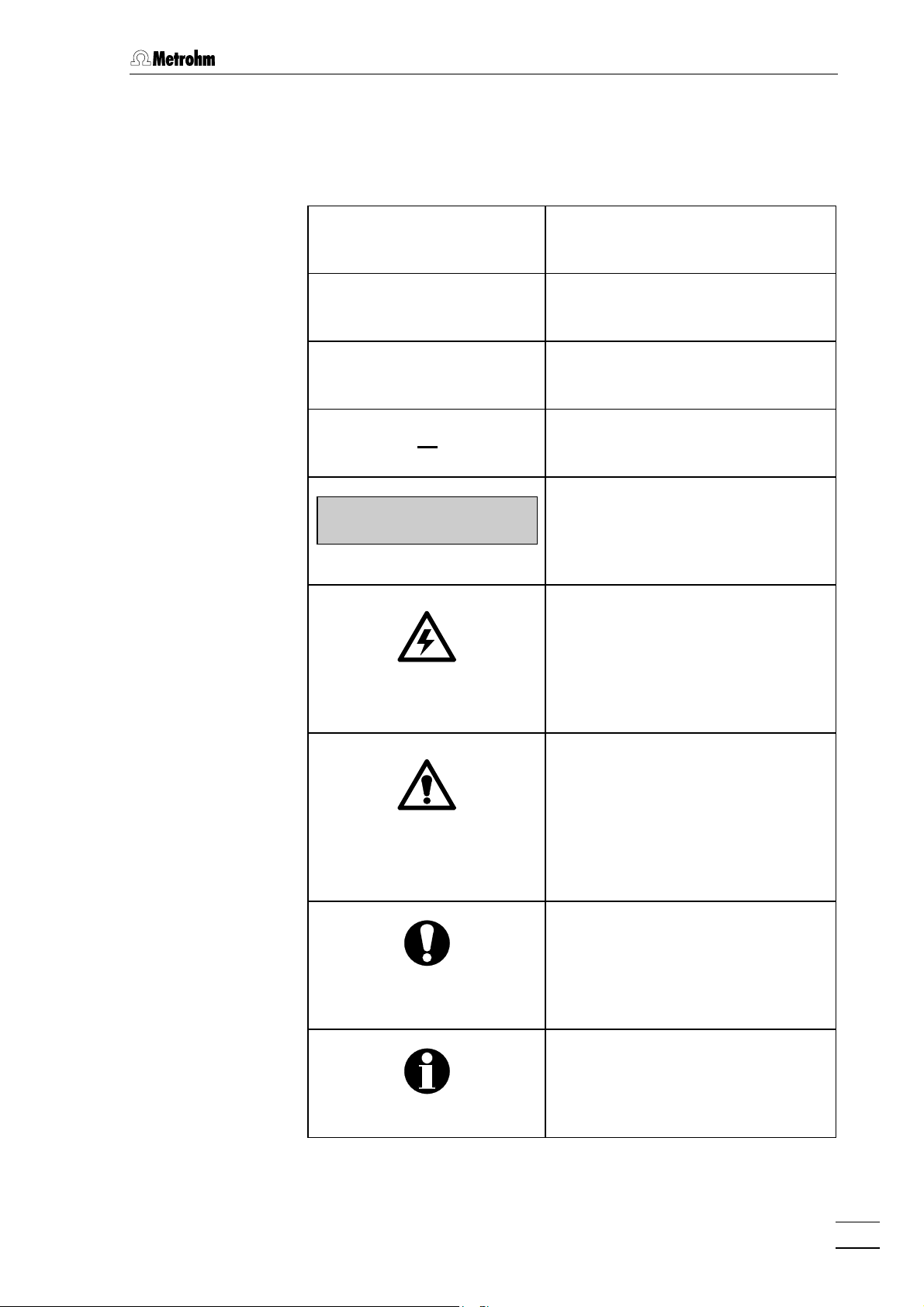
The following notations and pictograms (symbols) are used in these Instructions for Use:
<PARAM> Key
"Range" Parameter or entry value
3535 Part or control of 732/733
2222 Part or control of 709
1.3 Information on the Instructions for Use
>PARAM/detector
range: 1.00 mS/cm
Display
Text in display 11 of the 732 IC
Detector
Hazard
This symbol draws attention to a
possible danger to life or of injury if
the associated directions are not
followed correctly.
Warning
This symbol draws attention to
possible damage to instruments or
instrument parts if the associated
directions are not followed correctly.
Caution
This symbol marks important information. First read the associated
directions before you continue.
732 IC Detector / 733 IC Separation Center
Comment
This symbol marks additional information and tips.
9
Page 17
1 Introduction
1.4 Safety notes
1.4.1 Electrical safety
While electrical safety in the handling of the 732 IC Detector and 733
Separation Center is assured in the context of the specifications IEC
1010-1 (protection class 1, degree of protection IP40), the following
points should be noted:
• Mains connection
Setting of the mains voltage, checking the mains fuse and the
mains connection must be effected in accordance with the instruc-
tions in section 2.4.
• Opening the 732 IC Detector
If the 732 IC Detector is connected to the power supply, the instrument must not be opened nor must parts be removed from it, otherwise there is a danger of coming into contact with components which
are live. Hence, always disconnect the instrument from all voltage
sources before you open it and ensure that the mains cable is
disconnected from mains connection 18 18 !
• Opening the 733 IC Separation Center
Disconnect connecting cable to the 732 IC Detector from connector 1414 before you remove the middle housing panel with con-
nectors.
• Protection against static charges
Electronic components are sensitive to static charging and can be
destroyed by discharges. Before you touch any of the components
inside the 732 IC Detector or 733 IC Separation Center, you should
earth yourself and any tools you are using by touching an earthed
object (e.g. housing of the instrument or a radiator) to eliminate any
static charges which exist.
1.4.2 General precautionary rules
• Handling of solvents
Check all lines of the IC system periodically for possible leaks. Follow
the relevant instructions regarding the handling of flammable and/or
toxic solvents and their disposal.
10
732 IC Detector / 733 IC Separation Center
Page 18
2 Installation
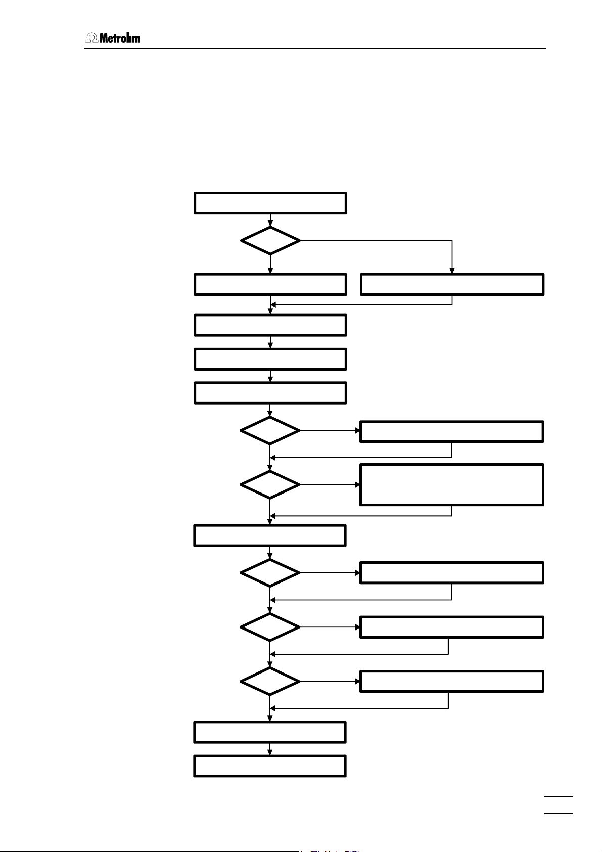
2.1 Flow chart
The following flow chart provides an overview of all installation work. You
will find more detailed information in the relevant sections.
2.1 Flow chart
Setting upSetting up
733.0X20733.0X20
NoNo
Connecting 733Connecting 733 sect. 2.3.1sect. 2.3.1 Connecting 733Connecting 733 sect. 2.3.2sect. 2.3.2
Installing accessoriesInstalling accessories sect. 2.3.3/4sect. 2.3.3/4
Mains connectionMains connection sect. 2.4sect. 2.4
Connecting 709 IC PumpConnecting 709 IC Pump sect. 2.6sect. 2.6
metal freemetal free
YesYes
PrecolumnPrecolumn
NoNo
sect. 2.2sect. 2.2
YesYes
NoNo
YesYes
PassivationPassivation sect. 2.6.7sect. 2.6.7
Precolumn with twin cartridge holderPrecolumn with twin cartridge holder sect. 2.7.2sect. 2.7.2
Precolumn with cartridge headPrecolumn with cartridge head sect. 2.7.3sect. 2.7.3
IC anion precolumn SUPERSEPIC anion precolumn SUPERSEP sect. 2.7.4sect. 2.7.4
Installing sample loopInstalling sample loop sect. 2.8.2sect. 2.8.2
ConditioningConditioning sect. 2.8.7sect. 2.8.7
Connecting external devicesConnecting external devices sect. 2.9sect. 2.9
732 IC Detector / 733 IC Separation Center
733.0010733.0010 Connecting separating columnConnecting separating column sect. 2.8.4sect. 2.8.4
NoNo
733.0X20733.0X20 Connecting separating columnConnecting separating column sect. 2.8.5sect. 2.8.5
NoNo
733.0X30733.0X30 Connecting sep. col. + suppressorConnecting sep. col. + suppressor sect. 2.8.6sect. 2.8.6
NoNo
YesYes
YesYes
YesYes
11
Page 19
2 Installation
2.2 Setting up the instruments
2.2.1 Packaging
The 732 IC Detector and 733 IC Separation Center are supplied
together with the separately packed accessories in special packagings
containing shock-absorbing foam linings designed to provide excellent
protection. The actual instruments are packed in an evacuated
polyethylene bag to prevent the ingress of dust. Please store all these
special packagings as only they assure transport of the instruments
free from damage.
2.2.2 Check
After receipt, immediately check whether the shipment is complete and
has arrived without damage (compare with delivery note and list of accessories in section 7.2). In the case of transport damage, see instructions in section 7.4.1 "Warranty".
2.2.3 Location
Position the instruments in the laboratory at a location convenient for
operation, free from vibrations and protected against a corrosive atmosphere and contamination by chemicals. The same applies to all
other components of the IC system.
To avoid disturbing temperature influences on the insulated column
compartment, the entire system including pump and eluent reservoir
must be protected against direct sunlight.
2.2.4 Arrangement of the instruments
In one-channel operation, the 709 IC Pump, 733 IC Separation Center
and 732 IC Detector are best stacked on top of one another in this order.
In two-channel operation (2.733.0X20 IC Separation Center), the optimum arrangement (1, 2 or 3 towers) depends on the laboratory space
available. However, the 709 IC Pumps should be set up at the very
bottom and the 732 IC Detectors at the very top.
12
To ensure that the arrangement of pumps and detectors for the two
channels A and B is clearly apparent in two-channel operation, it is
advantageous to mark the instruments. The 6.2248.000 Magnetic
plate is enclosed with the 732 IC Detector for this purpose. It can be
cut to the desired size, labeled (e.g. with "A" or "B") and affixed to the
appropriate instrument.
732 IC Detector / 733 IC Separation Center
Page 20
2.3 Connection of 733 IC Separation Center
2.3 Connection of 733 IC Separation Center
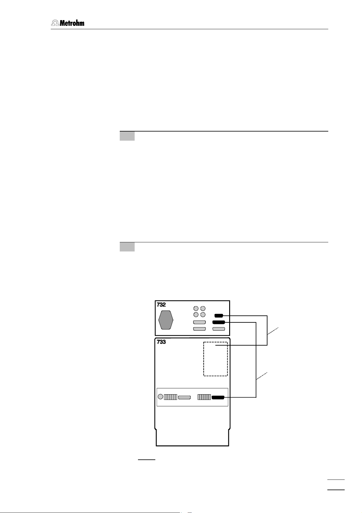
2.3.1 2.733.0010/2.733.0X30 IC Separation Center
The instrument versions 2.733.0010 and 2.733.0030 of the IC Separation Center are operated with a 732 IC Detector whose standard
equipment also includes the 1.732.0100 Detector block. For the
metal-free 2.733.0130 instrument version the metal-free 1.732.0110
Detector block must be used. It is best to proceed as follows when
connecting the two instruments and the detector block:
1 Install detector block
• Unscrew the four knurled screws 3434 from the top rear panel
3535 of the 733 IC Separation Center and remove rear panel
(see Fig. 5).
• Position detector block from the back in the space provided
in the 733 IC Separation Center on the right and push fully to
the front (see Fig. 16).
• Insert the cable permanently attached to the detector block in
opening 3333 and the outlet capillary in opening 3232 "Waste A" of
the rear panel 3535.
• Replace rear panel 3535 and screw to the 733 IC Separation
Center using the four knurled screws 3434.
2 Connect detector block
• Plug the gray connecting cable permanently attached to the
detector block into connection 1313 "Detector Block" of the 732
IC Detector and fasten to the instrument by tightening the
screws in the cable connector (see Fig. 6).
Cable from
detector block
6.2125.090
RUN
COM
Fig. 6: Connection 732 – 2.733.0010/2.733.0X30
732 IC Detector / 733 IC Separation Center
13
Page 21

2 Installation
3 Connect waste container
• Lead the outlet capillary of the detector block to a sufficiently
large waste container and fix in place.
4 Connect 732 to 733
• Plug one end of the 6.2125.090 Connecting cable into con-
nection 1414 "733 IC Separation Center” of the 732 IC Detector
and fasten to the instrument by tightening the screws in the
cable connector (see Fig. 6).
• Plug the other end of the 6.2125.090 Connecting cable into
connection 3636 "732 IC Detector" of the 733 IC Separation
Center and fasten to the instrument by tightening the screws
in the cable connector (see Fig. 6).
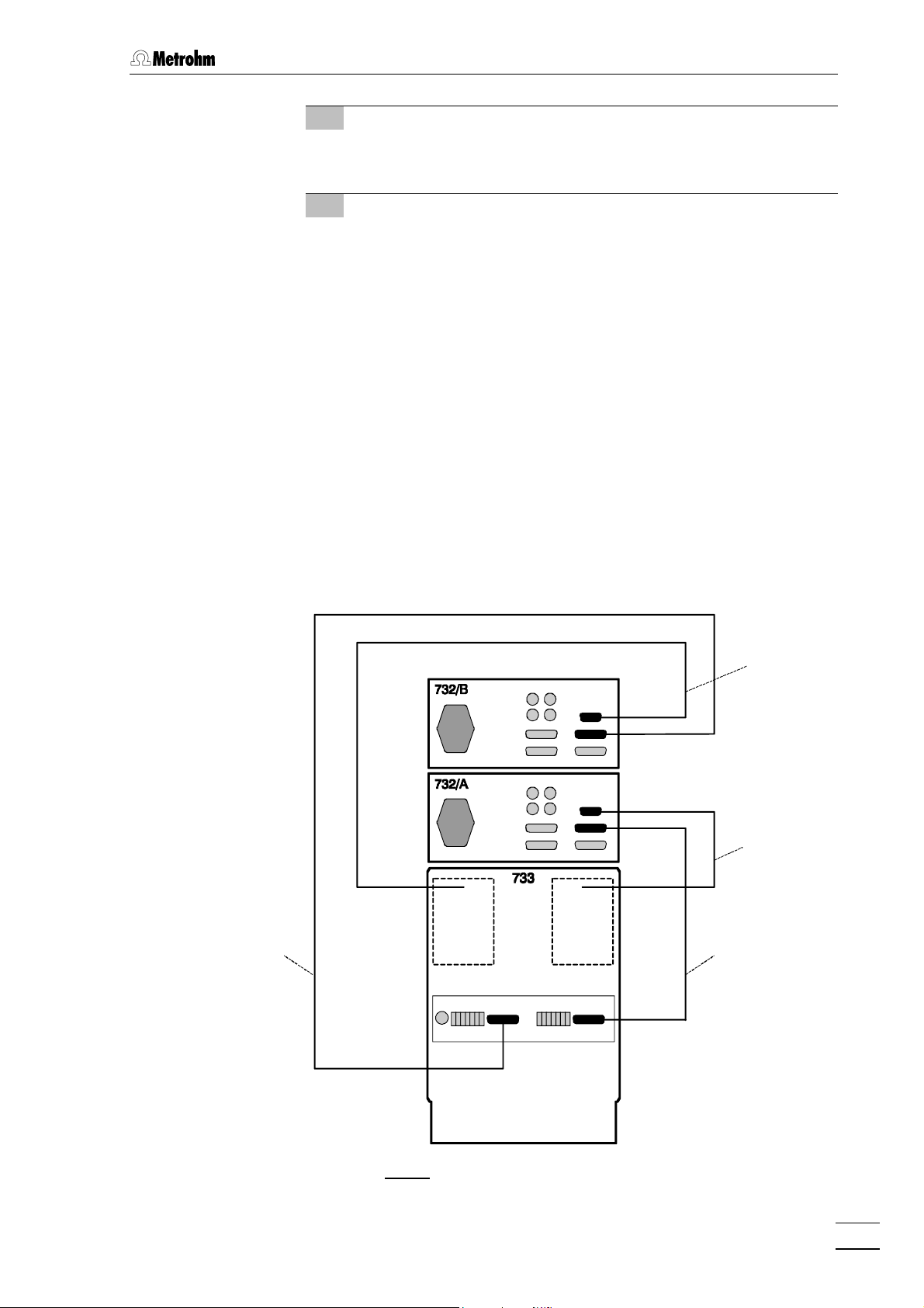
2.3.2 2.733.0X20 IC Separation Center
For operation of the 2.733.0020 or the metal-free 2.733.0120 instrument
version of the 733 Separation Center, two 1.732.0100 or metal-free
1.732.0110 IC Detectors are needed. It is best to proceed as follows
when connecting the instruments and the two detector blocks:
1 Install detector blocks
• Unscrew the four knurled screws 3434 from the top rear panel
3535 of the 733 IC Separation Center and remove rear panel
(see Fig. 5).
• Position first detector block A from the back in the space
provided in the 733 IC Separation Center on the right and
push fully to the front (see Fig. 16).
• Position second detector block B from the back in the space
provided in the 733 IC Separation Center on the left and push
fully to the front (see Fig. 16).
• Insert the cable permanently attached to detector block A in
opening 3333 and the outlet capillary in opening 32 32 "Waste A"
of the rear panel 3535.
• Insert the cable permanently attached to detector block B in
opening 2929 and the outlet capillary in opening 3030 "Waste B"
of the rear panel 3535.
• Replace rear panel 3535 and fasten to 733 IC Separation Center
with the four knurled screws 3434.
2 Connect detector blocks
• Plug the gray connecting cable permanently attached to
detector block A into connection 1313 "Detector block" of the
first 732 IC Detector and fasten to the instrument by tightening the screws in the cable connector (see Fig. 7).
• Plug the gray connecting cable permanently attached to
detector block B into connection 1313 "Detector Block" of the
second 732 IC Detector Block and fasten to the instrument by
tightening the screws in the cable connector.
14
732 IC Detector / 733 IC Separation Center
Page 22
2.3 Connection of 733 IC Separation Center
3 Connect waste container
• Lead the outlet capillaries of the two detector blocks to a
sufficiently large waste container and fix in place.
4 Connect 732 to 733
• Plug one end of the 6.2125.090 Connecting cable into con-
nection 1414 "733 IC Separation Center“ of the first 732 IC De-
tector and fasten to the instrument by tightening the screws
in the cable connector (see Fig. 7).
• Plug other end of the 6.2125.090 Connecting cable into
connection 3636 "732 IC Detector" of the 733 IC Separation
Center and fasten to the instrument by tightening the screws
in the cable connector.
• Plug one end of the 6.2125.090 Connecting cable into con-
nection 1414 "733 IC Separation Center" of the second 732 IC
Detector and fasten to the instrument by tightening the
screws in the cable connector.
• Plug the other end of the 6.2125.090 Connecting cable into
connection 4545 "732 IC Detector" of the 733 IC Separation
Center and fasten to the instrument by tightening the screws
in the cable connector.
Cable from
detector block
Cable from
detector block
6.2125.0906.2125.090
COM
RUN
732 IC Detector / 733 IC Separation Center
Fig. 7: Connection 732 – 2.733.0X20
15
Page 23

2 Installation
2.3.3 Connection of syringe and aspirating tubing
For manual filling of the sample loops mounted on the injection valves,
the 6.2816.020 Syringe and the PTFE aspirating tubing already screwed
to the valve are needed. These accessories are mounted or adjusted as
follows:
1 Connect syringe
• Push 6.2816.020 Syringe (without needle) as far as it will go
into connection socket 2121 (for valve A) or 2727 (for valve B)
(see Fig. 4).
2 Adjust aspirating tubing
• Loosen the rotary nipple screwed onto the interior side of
connection 2222 or 2828.
• Pull PTFE aspirating tubing 8888 (see Fig. 16 and Fig. 17) by
hand out of connection 2222 or 2828 as far as desired.
• Retighten rotary nipple on the interior side of connection 2222
or 2828 to fix the aspirating tubing in place.
2.3.4 Connection of the drain tube
The 733 IC Separation Center has a connection at the rear to which a
drain tube for discharged liquids can be attached. Proceed as follows:
1 Connect drain tube
• Mount 6.1816.00 Silicone tubing on connection nipple 4242
(see Fig. 5).
2 Lead drain tube to collecting vessel
• Lead the other end of the drain tube to a suitable collecting
vessel and fix in place.
2.3.5 Connection of the 6.5324.000 Bottle rack (option)
The optional available 6.5324.000 Bottle rack for supply vessels can be
placed on top of the IC system tower. The accessories include the
supply vessels for eluent (2 L), regeneration solution (1 L) and rinsing
solution (1 L). For the connection of the supply capillaries leading to the
709 IC Pump and the suppressor module, see the instructions given on
the enclosed leaflet.
16
732 IC Detector / 733 IC Separation Center
Page 24
2.4 Mains connection
Follow the instructions below for connecting to the power supply. If
the instrument is operated with a mains voltage set wrongly and/or
wrong mains fuse, there is a danger of fire!
2.4.1 Setting the mains voltage
Before switching on the 732 IC Detector for the first time, check that the
mains voltage set on the instrument (see Fig. 8) matches the local
mains voltage. If this is not the case, you must reset the mains voltage
on the instrument as follows:
1 Disconnect mains cable
Disconnect mains cable from mains connection plug 1818 of the
732 IC Detector.
2.4 Mains connection
2 Remove fuse holder
Using a screwdriver, loosen fuse holder 1919 below the mains
connection plug 1818 and take out completely.
3 Check and change fuse if necessary
Carefully take the fuse installed for the desired mains voltage out
of fuse holder 1919 and check its specifications (the position of the
fuse in the fuse holder is marked by the white arrow imprinted
next to the mains voltage range):
100……120 V 0.63 A (slow-blow) Metrohm No. U.600.0014
220……240 V 0.315 A (slow-blow) Metrohm No. U.600.0011
4 Insert fuse
Change fuse if necessary and reinsert in fuse holder 1919.
5 Install fuse holder
Depending on the desired mains voltage, insert fuse holder 1919 in
the 732 IC Detector so that the corresponding mains voltage
range can be read normally and the adjacent white arrow points
to the white bar imprinted below the fuse holder (see Fig. 8).
732 IC Detector / 733 IC Separation Center
17
Page 25
2 Installation
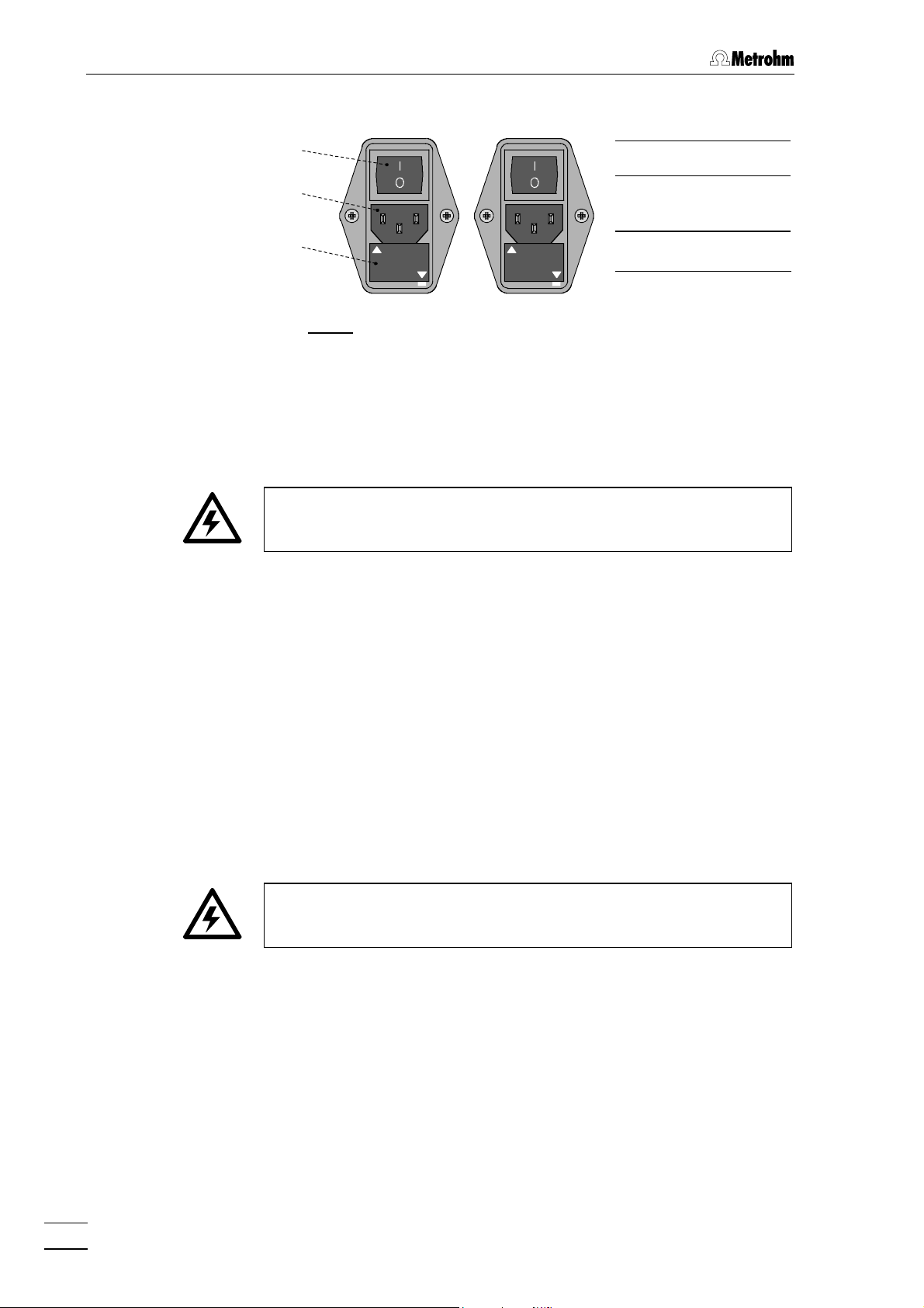
100 – 120 V220 – 240 V
2.4.2 Fuses
99
1818
99 Mains switch
1818 Mains con-
nection plug
1919
220 -- 240 V
100 -- 120 V
100 -- 120 V
220 -- 240 V
1919 Fuse holder
Fig. 8: Setting the mains voltage
One of the two fuses 0.63 A/slow-blow for 100…120 V or 0.315 A/slowblow for 220…240 V is installed in fuse holder 1919 of the 732 IC Detector
as standard.
Ensure that the instrument is never put into operation with fuses of
another type, otherwise there is danger of fire!
For checking or changing fuses, process as described in section 2.4.1.
2.4.3 Mains cable and mains connection
Mains cable
The instrument is supplied with one of three mains cables
• 6.2122.020 with plug SEV 12 (Switzerland, …)
• 6.2122.040 with plug CEE(7), VII (Germany, …)
• 6.2133.070 with plug NEMA 5-15 (USA, …)
which are three-cored and fitted with a plug with an earthing pin. If a
different plug has to be fitted, the yellow/green lead (IEC standard)
must be connected to protective earth (protection class 1).
Any break in the earthing inside or outside the instrument can make it
a hazard!
Mains connection
Plug the mains cable into mains connection plug 1818 of the 732 IC De-
tector (see Fig. 8).
2.4.4 On/off switching of the instruments
18
The 732 IC Detector is switched on and off using mains switch 99. When
the instrument is switched on, display 11 lights up.
732 IC Detector / 733 IC Separation Center
Page 26
2.5 Capillary connections
2.5.1 Capillaries
Some of the connections under high pressure between the feed pump
and the detector block must be set up by the user. For metal-free sys-
tems, the 6.1831.010 PEEK capillary (i.d. = 0.25 mm, e.d. = 1/16",
length = 3 m) must be used.
For non metal-free systems, the 6.1831.010 PEEK capillary can also
be used in the pressure range of 0…25 MPa (0…250 bar); on the other
hand, in the pressure range of 25…50 MPa (250…500 bar), which is
permissible only together with the non metal-free 2.709.0010 version of
the 709 IC Pump, the 6.2620.020 Steel capillary (i.d. = 0.25 mm,
e.d. = 1/16", length = 3 m) must be used.
With PEEK capillaries the connection is made preferably with the
6.2744.010 PEEK connectors, with steel capillaries, the connection is
made preferably with 6.2620.000 and 6.2620.010 steel connectors (see
section 2.5.2 and section 2.5.3).
2.5 Capillary connections
Capillaries fitted with new connectors must have a perfectly flat cut
surface. For PEEK capillaries it is best to use the 6.2621.080 Capil-
lary tubing cutter, for steel capillaries the 6.2621.040 Capillary
tubing cutter (both available as an option).
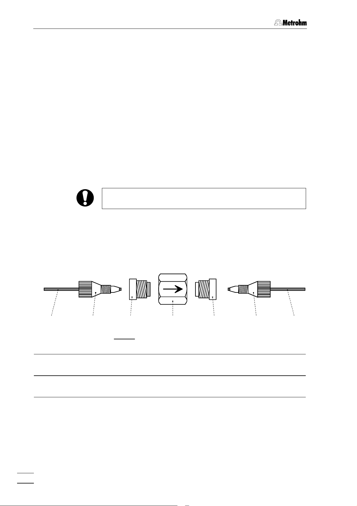
2.5.2 Steel connectors
For the connection of steel capillaries, the steel connectors 6.2620.010
Ferrule and 6.2620.000 Pressure screw available as an option can
be used. Proceed as follows:
1 Mount connectors
Slide a pressure screw 5050 (6.2620.000) and a ferrule 4949
(6.2620.010) over the end of the capillary 5151 to be fastened as
shown in Fig. 9.
2 Insert capillary in connection
Push capillary end into the corresponding connection as far as it
will go (to avoid dead volume).
3 Tighten compression fitting
Tighten pressure screw 5050 with the open-end spanner 1/4"
(6.2621.050) supplied.
For the connection of capillaries to the injection valves, use only the
special steel connections contained in a plastic bag affixed to the
valve (or as an alternative the 6.2744.010 PEEK compression fittings).
If other steel connectors are used (e.g. 6.2620.000 and 6.2620.010),
the valve connection may be damaged!
732 IC Detector / 733 IC Separation Center
19
Page 27
2 Installation
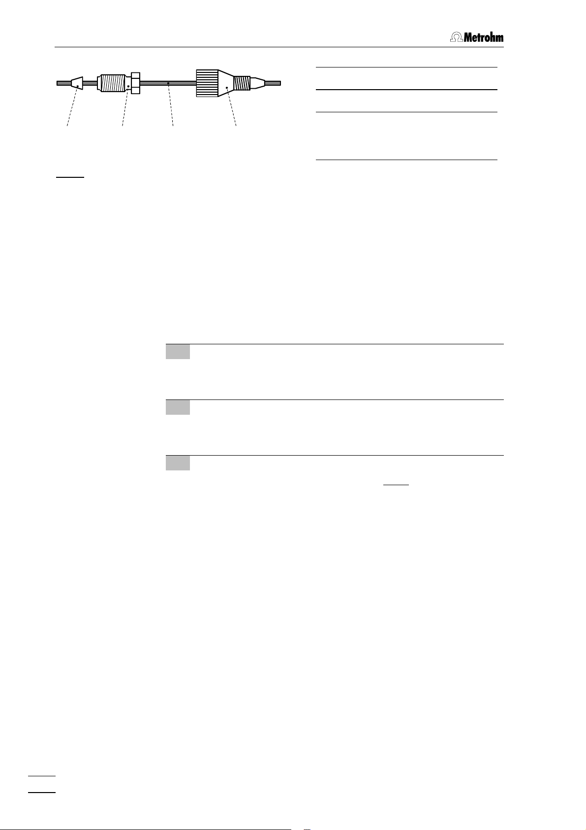
50504949 5151 5252
4949 Ferrule (6.2620.010)
5050 Pressure screw (6.2620.000)
5151 Capillary
6.2620.020 Steel capillary or
6.1831.010 PEEK capillary
Fig. 9: Connectors for capillaries
2.5.3 PEEK connectors
For the connection of 6.1822.010 PEEK capillaries (i.D. = 0.3 mm) or
6.1822.010 PTFE microcapillaries, the 6.2744.010 PEEK compres-
sion fittings are used. Proceed as follows:
1 Mount compression fitting
Slide a compression fitting 5252 (6.2744.010) over the end of the
capillary 5151 to be fastened as shown in Fig. 9.
2 Insert capillary in connection
Push capillary end in the corresponding connection as far as it
will go (to avoid dead volume).
5252 Compression fitting
(6.2744.010)
3 Tighten compression fitting
Tighten compression fitting 5252 by hand (never use tools).
20
732 IC Detector / 733 IC Separation Center
Page 28

2.6 Connection of 709 IC Pump
2.6.1 Electrical connection
For operation of the 732 IC Detector and 733 IC Separation Center you
can use any commercial HPLC pump. However, as the attainable sensitivity depends to a large extent on the quality of the pump, Metrohm
advises use of the 709 IC Pump, which has been specially developed
for the demands of ion chromatography and has minimal pump pulsation and an outstanding flow constancy.
Startup and operation of the 709 IC Pump are described in the 709
Instructions for Use. The eluent, which must be degassed and filtered
(cf. section 5.1.3), is selected on the basis of the separating column installed in the 733 IC Separation Center and the current separation
problem (see 8.732.2003 IC Monograph).
The connection of the 709 IC Pump at the connection 1515 of the 732
IC Detector is shown in Fig. 10. For this you can use the 6.2125.060
Cable available as an option or another RS cable specified as a "null
modem" cable. To ensure proper functioning of the communication
between the 732 IC Detector and 709 IC Pump, the sliding switch 3636 on
the IC pump must be set to "RS 232" and the external control switched
on with key 88 <EXT.> (see 709 Instructions for Use).
2.6 Connection of 709 IC Pump
732
709
Fig. 10: Connection of 709 IC Pump
2.6.2 Pulsation dampener
To protect the column material against pressure drops caused by the
injector, the use of a pulsation dampener connected between the pump
and the injection valve of the 733 IC Separation Center is recommended. The optional 6.2620.150 Pulsation dampener MF (see sec-
tion 7.3.1) is very well suited to this purpose.
6.2125.060
The metal-free 6.2620.150 Pulsation Dampener is supplied fully assembled and has two connections for capillaries, for which either the
connectors supplied or two 6.2744.010 PEEK compression fittings can
be used. The flow direction is arbitrary. The pulsation dampener is positioned in the interior of the 733 IC Separation Center on the base below the injection valve (see Fig. 16 and Fig. 17).
732 IC Detector / 733 IC Separation Center
21
Page 29
2 Installation
2.6.3 Filter unit PEEK
The 6.2821.100 Filter unit PEEK (see Fig. 11) supplied with the 709
IC Pump is installed between the 709 IC Pump and the injection valve
at the 733 IC Separation Center. This filter unit serves to avoid contamination of the piston seals of the 709 IC Pump by abrasive particles and
can be used in the pressure range 0…25 MPa (0…250 bar).
The two filter units PEEK supplied with the 2.733.0X30 IC Separation
Center (with suppressor) are installed between the 752 Pump Unit and
the inlet capillaries for regeneration and rinsing solution. These filter
units serve to protect the suppressor module from foreign particles and
bacterial growth.
The 6.2821.100 Filter unit PEEK consists of the housing 5454 and the two
connectors 5353 (with filter) and 5555 (without filter) screwed into the hous-
ing 5454. For the connection of capillaries 5151 PEEK compression fittings
5252 (6.2744.010) must be used. New connectors 5353 with filter are available as an option with the ordering number 6.2821.110 (set of 10).
For the connection of the filter unit, please note the flow direction
arrow printed on the housing.
5151 5252 5353 5454 5555 5252 5151
Fig. 11: 6.2821.100 Filter unit PEEK
5151 Capillary
6.1831.010 PEEK capillary
5252 Compression fitting (6.2744.010) 5555 Connector without filter
5353 Connector with filter (6.2824.110)
Part of 6.2824.100 Filter unit
22
5454 Housing for filter unit
Part of 6.2824.100 Filter unit
Part of 6.2824.100 Filter unit
732 IC Detector / 733 IC Separation Center
Page 30
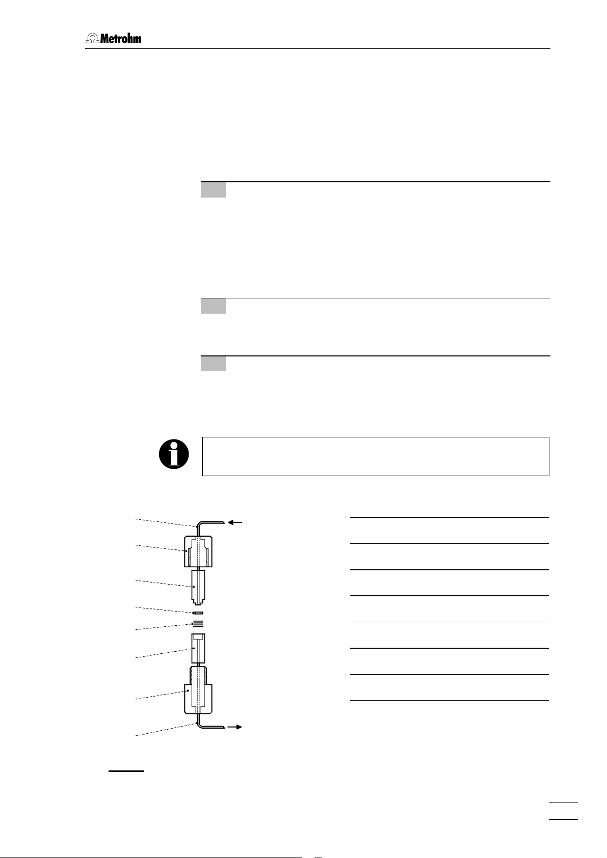
2.6.4 Filter unit Manufit
The optional 6.2821.000 Filter unit Manufit (see section 7.3.1) is installed between the 709 IC Pump and the injection valve at the 733 IC
Separation Center. The filter unit serves to avoid contamination of the
piston seals by abrasive particles and can be used in the pressure
range 0…50 MPa (0…500 bar) for non metal-free systems together
with steel capillaries. It is installed as follows (see Fig. 12):
1 Prepare Manufit housing
• Insert outlet capillary 6363 with steel mesh holding end 6161 into
Manufit housing 6262.
• Insert the 4 steel meshes 6060 provided into the steel mesh
holding end 6161.
• Press the PTFE gasket 5959 into the steel mesh holding end
6161.
2 Prepare Manufit pressure screw
• Insert inlet capillary 5656 with counterpart end 5858 into Manufit
pressure screw 5757.
2.6 Connection of 709 IC Pump
5656
5757
5858
5959
6060
6161
3 Assembly
• Fit the two capillary end pieces 5858 and 6161 together.
• Screw Manufit pressure screw 5757 and Manufit housing 6262
firmly together.
To replace contaminated steel meshes, proceed in the reverse order.
IC Pump
709
5656 Inlet capillary
5757 Manufit pressure screw
5858 Counterpart end
5959 PTFE Gasket (6.2821.010)
6060 Steel meshes (6.2821.020)
6161 Steel mesh holding end
6262
IC Separation
6363
Fig. 12: 6.2821.000 Filter unit Manufit
732 IC Detector / 733 IC Separation Center
Center 733
6262 Manufit housing
6363 Outlet capillary
23
Page 31

2 Installation
2.6.5 Connection to injection valve with PEEK capillaries
For metal-free systems and for non metal-free systems in the pressure
range 0…25 MPa (0…250 bar) we recommend to use 6.1831.010
PEEK capillaries, a 6.2620.150 Pulsation dampener (see section 2.6.2)
and a 6.2821.100 Filter unit PEEK (see section 2.6.3) to connect the
709 IC Pump and the injection valve of the 733 IC Separation Center.
Proceed as follows:
For the connection of capillaries to the injection valve, use only the
6.2744.010 PEEK compression fittings. If other steel connectors are
used (e.g. 6.2620.000 and 6.2620.010), the valve connection may be
damaged!
1 Connection to 709 IC Pump
• Cut connection capillary 2222 (6.1831.010 PEEK capillary) to
the required length and equip with the necessary connectors.
• Attach one end of connection capillary 2222 to connection 2323 of
the 709 IC Pump (see 709 Instructions for Use).
• Attach the other end of connection capillary 2222 to the con-
nector 5353 (with filter) of the filter unit 6464 (see Fig. 13).
• Attach the PEEK capillary 6565 cut to the required length and
equipped with connectors to the connector 5555 of the filter unit
6464.
2 Installation of the capillary in the IC Separation
Center
• Unscrew the four knurled screws 3737 of the bottom rear panel
3939 of the 733 IC Separation Center and remove rear panel
(see Fig. 5).
• Insert PEEK capillary 6565 from the back into the inner com-
partment of the IC Separation Center.
• Install rear panel 3939 so that the capillary is positioned in
opening 4040 „Inlet A“ or 4444 „Inlet B“ and screw on with the four
knurled screws 3737.
3 Connection to injection valve
• Connect PEEK capillary 6565 to pulsation dampener 6666 (see
section 2.6.2). Using another PEEK capillary 6565, connect pul-
sation dampener 6767 to connection "5" of injection valve 6868.
4 Mount column connection capillary
• Connect column connection capillary 6767 (ca. 20 cm of
6.1831.010 PEEK capillary) to connection "4" of injection valve
6868.
24
732 IC Detector / 733 IC Separation Center
Page 32

2.6 Connection of 709 IC Pump
2222 6464 6565
709
6666 65656767 6868
733
Fig. 13: Connection to injection valve with PEEK capillaries
2222 Connection capillary
6666 Pulsation dampener (6.2620.150)
6.1831.010 PEEK capillary
6464 Filter unit PEEK (6.2824.100) 6767 Column connection capillary
6.1831.010 PEEK capillary
6565 PEEK capillary (6.1831.010) 6868 Injection valve
2.6.6 Connection to injection valve with steel capillaries
For the pressure range 25…50 mPa (250…500 bar) we recommend to
use 6.2620.020 Steel capillaries, a 6.2620.150 Pulsation dampener (see
section 2.6.2) and a 6.2821.000 Filter unit Manufit (see section 2.6.4) to
connect the 709 IC Pump and the injection valve of the 733 IC Separation Center. Proceed as follows:
For the connection of capillaries to the injection valve, use only the
special steel connectors contained in a plastic bag affixed to the
valve. If other steel connectors are used (e.g. 6.2620.000 and
6.2620.010), the valve connection may be damaged!
1 Connection to 709 IC Pump
• Attach inlet capillary 5656 of the Manufit filter unit 6969 to connec-
tion 2323 of the 709 IC Pump (see 709 Instructions for Use).
• Attach outlet capillary 6363 of the filter unit Manufit 6969 using
coupling 7070 to a steel capillary 7171 cut to the required length
(see Fig. 14).
732 IC Detector / 733 IC Separation Center
25
Page 33

2 Installation
2 Installation of the capillary in the IC Separation
Center
• Unscrew the four knurled screws 3737 of the bottom rear panel
3939 of the 733 IC Separation Center and remove rear panel
(see Fig. 5).
• Insert steel capillary 7171 from the back into the inner com-
partment of the IC Separation Center.
• Install rear panel 3939 so that the capillary is positioned in
opening 4040 „Inlet A“ or 4444 „Inlet B“ and screw on with the four
knurled screws 3737.
3 Connection to injection valve
• Connect steel capillary 7171 to pulsation dampener 6666 (see
section 2.6.2). Using another steel capillary 7171, connect pul-
sation dampener 6666 to connection "5" of injection valve 6868.
4 Mount column connection capillary
• Connect column connection capillary 6767 (ca. 20 cm of
6.1831.010 PEEK capillary) to connection "4" of injection valve
6868.
5656 7070
709
Fig. 14: Connection to injection valve with steel capillaries
5656 Inlet capillary
of Filter unit Manufit 6969
6363 Outlet capillary
of Filter unit Manufit 6969
6666 Pulsation dampener (6.2620.150) 7070 Coupling (6.2620.060)
6767 Column connection capillary
6.2620.020 Steel capillary
6868 Injection valve
6969 Filter unit Manufit (6.2821.000)
7171 Steel capillary (6.2620.020)
71716969 6363 7171 6666 6767 6868
733
26
732 IC Detector / 733 IC Separation Center
Page 34

2.6.7 Passivation of the IC system
With non metal-free IC systems, the entire IC system (without precolumn, separating column and suppressor module) must be passivated
with nitric acid before being put into operation for the first time. Proceed
as follows:
1 Connect detector block to injection valve
• Connect column connection capillary 6767 using a 6.2620.060
Coupling directly to inlet capillary 8282 of the detector block
(see Fig. 16).
2 Set injection valve to "INJECT"
• Switch on 732 IC Detector using mains switch 99.
• Press key 2424 or 2626 <INJECT> on 733 IC Separation Center.
The green LED in the key should light up to show that the injection valve is in the position "INJECT".
2.6 Connection of 709 IC Pump
3 Rinse with HNO
3
• Immerse aspirating capillary of the 709 IC Pump in c(HNO3)
= 0.2 mol/L.
• Set a flow rate of 1 mL/min on the 709 IC Pump.
• Switch on 709 IC Pump and rinse IC system for ca. 10 min.
During this time, check all capillaries and their connections
between the 709 IC Pump and the detector block for escaping liquid. Should liquid escape at any position, the appropriate compression fitting must be tightened more or changed.
• Switch off 709 IC Pump.
4 Rinse with dist. H2O
• Immerse aspirating capillary of the 709 IC Pump in distilled or
demineralised water.
• Switch on 709 IC Pump and rinse the IC system for ca.
10 min.
• Switch off 709 IC Pump.
5 Rinse with eluent
• Immerse aspirating capillary of the 709 IC Pump in the eluent
which will be needed for the separating column used later.
• Switch on 709 IC Pump and rinse IC system until the absolute
conductivity shown on the 732 Detector is stable.
• Switch off 709 IC Pump.
6 Remove coupling
732 IC Detector / 733 IC Separation Center
• Remove 6.2620.060 Coupling between column outlet capillary 7171 and inlet capillary 8282 (see Fig. 16). The IC system is
now ready for the installation of precolumns, separating columns and suppressor module.
27
Page 35

2 Installation
2.7 Precolumns
2.7.1 General information on precolumns
The use of easily exchangeable precolumns protects the separating
columns and prolongs their lifetime. The precolumns available from
Metrohm (see section 7.3.2) are either real precolumns or precolumn
cartridges, which are used together with the 6.2821.050 Twin cartridge
holder or a 6.2821.040 Cartridge head.
New IC precolumns are normally filled with solution and sealed at
both ends. Before the precolumn is installed in the system, it must be
ensured that this solution is freely miscible with the eluent used
(check manufacturer's specifications).
2.7.2 Precolumns with twin cartridge holder
The precolumn cartridges are installed in the 6.2821.050 Twin cartridge
holder as follows (see Fig. 15):
1 Install cartridge
• Insert inlet capillary 7575 with end piece for precolumn cartridge
in Manufit housing 6262.
• Insert outlet capillary 7272 with end piece for precolumn car-
tridge in Manufit pressure screw 5757.
• Remove end caps from the precolumn cartridge 7474 (the steel
mesh 7373 and gaskets 5959 are already inserted in the car-
tridge).
• Fit the two capillary end pieces onto the precolumn cartridge
7474 (comply with the flow direction if specified on the column).
• Screw Manufit pressure screw 5757 and Manufit housing 6262
firmly together.
2 Connect precolumn
• Fit connectors to inlet capillary 7575 of the assembled precol-
umn (see section 2.5).
• Connect inlet capillary 7575 either using 6.2620.060 Coupling to
the column connection capillary 6767 mounted on the injection
valve (see section 2.6.4) or directly to connection "4“ of injection valve A or B.
• Shorten outlet capillary 7272 of the precolumn to ca. 5 cm and
mount the connectors (see section 2.5).
28
3 Rinse the precolumn
• Place a beaker beneath outlet capillary 7272.
• Switch on 709 IC Pump, rinse precolumn for ca. 10 min with
eluent and then switch off 709 IC Pump.
732 IC Detector / 733 IC Separation Center
Page 36

2.7 Precolumns
Cartridge head
Twin cartridge holder
7272
5757
5959
7373
7474
7373
5959
with 6.2821.050
Säule
with 6.2821.040
7676
7777
6060
5959
7878
5959
7373
7474
7373
5959
7979
6262
8080
4949
7575
5050
6767
Injektor
Injektor
Fig. 15: Installing precolumn cartridges
4949 Ferrule (6.2620.010) 7373 2 Steel meshes (6.2821.020)
5050 Pressure screw (6.2620.000) 7474 Precolumn cartridge
5757 Manufit pressure screw 7575 Inlet capillary
5959 PTFE gasket (6.2821.010) 7676 IC separating column
6060 4 Steel meshes (6.2821.020) 7777 Manufit pressure screw
6262 Manufit housing 7878 Steel spacer (6.2821.080)
6767 Column connection capillary of
injector
7272 Outlet capillary 8080 Manufit housing
732 IC Detector / 733 IC Separation Center
7979 Steel connector for ferrule
(of IC separating column)
29
Page 37

2 Installation
2.7.3 Precolumns with cartridge head
The precolumn cartridges are installed in the 6.2821.040 Cartridge
head as follows (see Fig. 15):
1 Prepare separating column
• Remove end caps from separating column 7676.
• Unscrew fastening screw from column inlet.
• Take steel connector 7979 for ferrule out of fastening screw.
2 Install cartridge
• Remove end caps for precolumn cartridge 7474 (the steel mesh
7373 and gaskets 5959 are already installed in the cartridge).
• Mount steel spacer 7878 on separating column 7676.
• Mount precolumn cartridge 7474 on the steel spacer (comply
with flow direction if specified on the precolumn).
• Screw Manufit pressure screw 7777 firmly to separating column
7676.
• Mount steel connector 7979 for ferrule on the inlet side of the
precolumn cartridge 7474.
• Screw on Manufit housing 8080 with Manufit pressure screw 7777.
3 Connect precolumn
• Fit connectors to the column connection capillary 6767
mounted on the injection valve (see section 2.5).
• Screw column connection capillary 6767 to Manufit housing 8080.
30
732 IC Detector / 733 IC Separation Center
Page 38

2.7.4 IC anion precolumn SUPERSEP
The 6.1009.010 IC Anion Precolumn SUPERSEP has two connections
for steel or PEEK capillaries and is installed as follows:
1 Connect precolumn
• Remove end caps from the precolumn.
• Fit connectors to column connection capillary 6767 mounted on
the injection valve (see section 2.5).
• Screw precolumn to column connection capillary 6767.
• Cut a piece from the 6.2620.020 Steel capillary or the
6.1831.010 PEEK capillary as short as possible and fit with
connectors (see section 2.5).
• Fasten the prepared capillary to the other end of the precol-
umn.
2 Rinse precolumn
• Place a beaker beneath the outlet capillary of the precolumn.
• Switch on 709 IC Pump and rinse precolumn with eluent for
ca. 10 min.
• Switch off IC pump.
2.7 Precolumns
732 IC Detector / 733 IC Separation Center
31
Page 39

2 Installation
2.8 Separating columns and suppressor module
2.8.1 General information on separating columns
New IC separating columns are normally filled with solution and
sealed at both ends. Before the column is installed in the system, it
must be ensured that this solution is freely miscible with the eluent
used (check manufacturer's specifications).
The IC separating columns and precolumns currently available from
Metrohm are listed in section 7.3.2. A test chromatogram and an information leaflet is provided with each column. You will find additional information concerning these columns in the 8.732.2003 Metrohm Monograph «Ion chromatography» and in special "Application Bulletins",
which are available on request free of charge from your local Metrohm
agency.
When you install the column, always ensure that this is inserted correctly in accordance with the flow direction shown (arrow must point
upwards).
2.8.2 Selection of the sample loop
Selection of the sample loop depends on the separating column used.
Normally, the following sample loops are used:
Anion columns 100 µL
Cation columns 10 µL
Columns for suppressor technique 20 µL
Depending on the instrument version, the following sample loops are
installed in the 733 IC Separation Center:
Version Valve Sample loop Volume
2.733.0010 A 6.2620.120 (steel) 100 µL
2.733.0020 A 6.2620.120 (steel) 100 µL
B 6.2620.100 (steel) 10 µL
2.733.0030 A 6.1825.210 (PEEK) 20 µL
2.733.0120 A 6.1825.220 (PEEK) 100 µL
B 6.1825.230 (PEEK) 10 µL
2.733.0130 A 6.1825.210 (PEEK) 20 µL
32
If desired, the built-in sample loop can be replaced by one of the sample loops available as an option (see section 7.3.1).
732 IC Detector / 733 IC Separation Center
Page 40

2.8 Separating columns and suppressor module
2.8.3 General information on suppressor module
The Metrohm Suppressor Module MSM for chemical suppression
installed in the 2.733.0X30 IC Separation Center comprises a total of 3
suppressor units which are in turn used for suppression, regenerated
with sulfuric acid and rinsed with water. To record every new chromatogram under comparable conditions, work is normally carried out with
freshly regenerated suppressor. Switching is either automatic together
with the valve switching or manual.
The suppressor units must never be regenerated with H2SO4 in the
same flow direction used for the eluent. You should thus always install
the inlet and outlet capillaries as described in section 2.8.6 according
to the scheme shown in Fig. 18.
For operation of the suppressor module, a two-channel peristaltic
pump is needed which conveys the regeneration solution (normally
20 mmol/L H2SO4) and the rinsing solution (normally dist. H2O) to the
suppressor units. We advise working with a flow rate of 0.5 mL/min.
The 752 Pump Unit is available from Metrohm as an option. Two
lengths of pump tubing (6.1826.050) are enclosed with this pump
(flow rate 0.5 mL/min). Startup and operation of the 752 Pump Unit is
described in the Instructions for Use enclosed with the pump.
The three inlets and outlets numbered 1...3 on the suppressor module
each have 2 permanently mounted PTFE capillaries, which must be
connected as described in section 2.8.6 (see Fig. 16 and Fig. 17).
To avoid contamination of the suppressor module by foreign particles
or bacterial growth, it is advantageous to install an in-line filter between the 752 Pump Unit and the suppressor module. The two
6.2821.100 Filter units PEEK (see section 2.6.3) supplied with the
2.733.0X30 IC Separation Center are eminently suitable for this purpose.
The suppressor module must never be switched in the dry state as
there is a danger of blocking. Before every switching operation of the
suppressor module, the three suppressor units must have been
rinsed for at least ½ h with eluent, regeneration and rinsing solution.
732 IC Detector / 733 IC Separation Center
33
Page 41

2 Installation
8181
8282
8383
8484
7676
6868
8383
8484
6767
8585
6666
FILL INJECT
A B
8686 8787 8888
Fig. 16: Interior of the 2.733.0010 IC Separation Center
6565 Capillary to 709 IC Pump 8383 Mounting rail
6666 Pulsation dampener (6.2620.150) 8484 Column holder (6.2027.0X0)
6767 Column connection capillary 8585 Capillary for syringe
STEP
FILL INJECT
6565
PEEK capillary, fixed mounting
6868 Injection valve 8686 Sample loop (6.2620.120)
100 µL, fixed mounting, steel
7676 IC separating column 8787 Inlet capillary for injector
Steel or PEEK capillary
8181 Detector block 8888 PTFE aspirating tubing
fixed mounting
8282 Inlet capillary for detector block
Steel capillary, fixed mounting
34
732 IC Detector / 733 IC Separation Center
Page 42

2.8 Separating columns and suppressor module
2.8.4 One-channel system without suppressor module
With the one-channel system without suppressor module, the IC separating column is installed in the 2.733.0010 IC Separation Center as
follows (see Fig. 16):
1 Connect column to injector
• Remove end caps from column 7676.
• without precolumn:
Screw inlet end of separating column 7676 (note flow direction)
to column connection capillary 6767 mounted on the injector.
• with precolumn in twin cartridge holder:
Screw inlet end of separating column 7676 (note flow direction)
to outlet capillary 7272 (see Fig. 15).
• with precolumn in cartridge head:
Install separating column 7676 (note flow direction) in the car-
tridge head (see Fig. 15) as described in section 2.7.3.
2 Rinse column
• Place a beaker beneath the column outlet.
• Switch on 709 IC Pump and rinse the column for ca. 10 min
with eluent.
• Switch off IC Pump.
3 Connect column to detector block
• Screw outlet end of separating column 7676 to the inlet capillary
8282 permanently mounted on the detector block.
4 Fix column
• Insert one or two column holders 8484 (6.2027.030, 6.2027.040
or 6.2027.050) in the mounting rails 8383 and fasten separating
column in the column holder.
2.8.5 Two-channel system without suppressor module
With the two-channel system without suppressor module (2.733.0X20
IC Separation Center), the first IC separating column is connected on
the left side to injection valve A and detector block A as with the onechannel system (see section 2.8.4 and Fig. 16). The second column is
connected on the right side to injection valve B and detector block B in
an analogous manner.
732 IC Detector / 733 IC Separation Center
35
Page 43

2 Installation
8989
8383
8484
7676
6868
8383
8484
6767
8585
6666
FILL INJECT
A B
2
STEP
FILL INJECT
8181
8282
8383
8484
9696
1
3
9595
9494
9393
9292
8686 9090 9191
6565
88888787
Fig. 17: Interior of the 2.733.0X30 IC Separation Center
4343 Rear panel opening 8383 Mounting rail
6565 Capillary to 709 IC Pump 8484 Column holder (6.2027.0X0)
6666 Pulsation dampener (6.2620.150) 8585 Capillary for syringe
PEEK capillary, fixed mounting
6767 Column connection capillary
PEEK capillary
6868 Injection valve 8787 Inlet capillary for injector
7676 IC separating column 8888 PTFE aspirating tubing
8181 Detector block 8989 Suppressor inlet capillary for
8282 Inlet capillary for detector
block (fixed mounting)
8686 Sample loop (6.1825.210)
20 µL, fixed mounting, PEEK
Steel or PEEK capillary
fixed mounting
eluent
9090 Suppressor inlet capillary for
H2SO
4
36
732 IC Detector / 733 IC Separation Center
Page 44

2.8 Separating columns and suppressor module
9191 Suppressor outlet capillary for
H2SO
4
9292 Suppressor outlet capillary for
9494 Suppressor outlet capillary
for eluent
9595 Suppressor module
H2O
9393 Suppressor inlet capillary for
H2O
9696 Coupling (6.2620.060; steel) or
Coupling (6.2744.040; PEEK)
2.8.6 One-channel system with suppressor module
In the case of the one-channel system with suppressor module, first the
IC separating column is installed in the 2.733.0X30 IC Separation Center (see Fig. 17) and then the suppressor module is connected to the
752 Pump Unit needed for operation (see Fig. 18). Proceed as follows:
1 Connect column to injector
• Remove end caps from column 7676.
• without precolumn:
Screw inlet end of separating column 7676 (note flow direction)
to column connection capillary 6767 mounted on the injector.
• with precolumn in twin cartridge holder:
Screw inlet end of separating column 7676 (note flow direction)
to outlet capillary 7272 (see Fig. 15).
• with precolumn in cartridge head:
Install separating column 7676 (note flow direction) in the car-
tridge head as described in section 2.7.3 (see Fig. 15).
2 Rinse column
• Place a beaker beneath the column outlet.
• Switch on 709 IC Pump and rinse column with eluent for ca.
10 min.
• Switch off IC pump.
3 Connect column to suppressor module
• Cut inlet capillary 8989 marked with "Eluent" of suppressor
module 9595 to the desired length using a sharp cutting tool
(e.g. razor blade).
• Screw inlet capillary 8989 to outlet end of separating column 7676
using a 6.2744.010 Compression fitting.
4 Fix column
• Insert one or two column holders 8484 (6.2027.030, 6.2027.040
or 6.2027.050) in mounting rails 8383 and fasten separating
column in the column holder.
5 Connect suppressor module to detector block
• Cut outlet capillary 9494 marked with "Detector" of suppressor
module 9595 to the desired length using a sharp cutting tool
(e.g. razor blade).
732 IC Detector / 733 IC Separation Center
37
Page 45

2 Installation
Eluent
H2O
Detector
Waste
Waste
H
SO
8989 Suppressor inlet
capillary for eluent
8989
94949090
1
2
3
9191
9393
9292
Fig. 18: Connections at suppressor module
• Screw outlet capillary 9494 to coupling 9696 using a 6.2744.010
Compression fitting.
• Screw inlet capillary 8282 of detector block 8181 to other end of
coupling 9696.
6 Fix connection suppressor – detector block
• Insert one of the column holders 8484 (6.2027.030, 6.2027.040
or 6.2027.050) in mounting rail 8383 and fasten coupling 9696 in
the column holder.
9090 Suppressor inlet
capillary for H2SO
9191 Suppressor outlet
capillary for H2SO
9292 Suppressor outlet
capillary for H2O
9393 Suppressor inlet
capillary for H2O
9494 Suppressor outlet
capillary for eluent
4
4
7 Prepare 752 Pump Unit
• Take two tubing cartridges out of the holder of the 752 Pump
Unit.
• Lay a length of 6.1826.050 Pump tubing in each of the two
tubing cartridges and reinsert these in the holder without
kinking the pump tubing.
• Regulate contact pressure on pump tubing in accordance
with the instructions printed on the pump.
Pump tubing is consumable material with a lifetime which depends on
the contact pressure. For this reason, raise the tubing cartridges
completely by loosening the clip on the right if the pump is switched
off for some considerable time (the set contact pressure remains
unchanged).
8 Suppressor connection 2: H2SO
4
• Loosen rotary nipple screwed onto the interior side of con-
nection 2727. Pull inlet capillary 9090 marked with "H2SO4" (see
Fig. 17 and Fig. 18) by hand out of the opening of connection
2727 as far as required. Retighten nipple on the interior side of
connection 2727 to fix inlet capillary 9090.
38
732 IC Detector / 733 IC Separation Center
Page 46

2.8 Separating columns and suppressor module
• Attach inlet capillary 9090 using a 6.2744.010 Compression
fitting to the connector 5555 of the filter unit PEEK (see section
2.6.3).
• Attach a piece of the 6.1803.020 PTFE tubing (from 752
accessories) cut to the required length using a 6.2744.010
Compression fitting to the connector 5353 with filter at the other
end of the Filter unit PEEK.
• Attach the other end of the PTFE tubing using a 6.2744.010
Compression fitting to the 6.2744.030 Coupling (from 752 accessories) and mount it on the outlet end of the first length of
pump tubing.
• Mount a 6.2744.030 Coupling to the inlet end of the first
length of pump tubing. Attach a piece of the 6.1803.020 PTFE
tubing (aspirating tubing, from 752 accessories) cut to the
required length using a 6.2744.010 Compression fitting to the
other end of this coupling.
• Immerse the other end of the aspirating tubing in a vessel
containing regeneration solution (normally 20 mmol/L H2SO4)
and fix in place.
• Pull outlet capillary 9191 marked with "Waste" of the suppressor
module through the rear panel opening 4343, lead it to a suffi-
ciently large waste container and fix it in place.
9 Suppressor connection 3: H2O
• Loosen rotary nipple screwed onto the interior side of connection 2828. Pull inlet capillary 9393 marked with "H2O" (see
Fig. 17 and Fig. 18) by hand out of the opening of connection
2828 as far as required. Retighten nipple on the interior side of
connection 2828 to fix inlet capillary 9393.
• Attach inlet capillary 9393 using a 6.2744.010 Compression
fitting to the connector 5555 of the filter unit PEEK (see section
2.6.3).
• Attach a piece of the 6.1803.020 PTFE tubing (from 752
accessories) cut to the required length using a 6.2744.010
Compression fitting to the connector 5353 with filter at the other
end of the Filter unit PEEK.
• Attach the other end of the PTFE tubing using a 6.2744.010
Compression fitting to the 6.2744.030 Coupling (from 752 accessories) and mount it on the outlet end of the second
length of pump tubing.
• Mount a 6.2744.030 Coupling to the inlet end of the second
length of pump tubing. Attach a piece of the 6.1803.020 PTFE
tubing (aspirating tubing, from 752 accessories) cut to the
required length using a 6.2744.010 Compression fitting to the
other end of this coupling.
• Immerse the other end of the aspirating tubing in a vessel
containing rinsing solution (normally dist. H2O) and fix in
place.
• Pull outlet capillary 9292 marked with "Waste" of the suppressor
module through the rear panel opening 4343, lead it to a suffi-
ciently large waste container and fix it in place.
732 IC Detector / 733 IC Separation Center
39
Page 47

2 Installation
2.8.7 Leak testing and conditioning
Before sample solutions can be injected in the IC system, the entire
system must be tested for leaks and then conditioned with eluent until
the baseline is stable. Proceed as follows:
1 Switch on 709 IC Pump
• Immerse aspirating capillary of the 709 IC Pump in eluent.
• Set flow rate recommended on the 709 IC Pump for the
separating column used (normally 0.5…2 mL/min).
• Set maximum shutoff pressure on the 709 IC Pump
(normally ca. 3 MPa above the pressure observed with the
column used).
• Switch on 709 IC Pump.
2 Check for leaks
• Check all capillaries and their connections between the 709
IC Pump and the detector block for escaping liquid. If eluent
escapes anywhere, the appropriate compression fitting must
be tightened further or changed.
3 Switch on 732 IC Detector
• Switch on 732 IC Detector with mains switch 99.
• Set operating temperature: Under the <CONFIG> key,
enter the desired value for the parameter "thermostat"
(default value = 35 °C).
• Enter cell constant: Under the <CONFIG> key, enter the
value printed on the detector block for the parameter "cell
constant".
• Set measuring range: Under the <PARAM> key, set the
parameter "range" so that the displayed absolute conductivity
value of the eluent lies within the selected range (default
value = 1 mS/cm).
• Set full-scale range: Under the <PARAM> or <FULL
SCALE> key, enter the desired value for the parameter "full
scale" (default value = range/1). To start with, it is advisable
not to set too narrow a full-scale range as the conductivity of
the eluent in the conditioning phase can change greatly until
attainment of a stable temperature.
4 Condition IC system
• Rinse the IC system with eluent until the desired stability of
the baseline is reached (normally 30…60 min; if the eluent is
changed, the establishment of the ion exchanger equilibrium
on the separating column can take longer).
40
5 Condition suppressor (if present)
• Load method "Prep-MSM" and start this method. The suppres-
sor module is switched to the next position every 20 min and
in this way conditioned.
732 IC Detector / 733 IC Separation Center
Page 48

2.9 Connection of external devices
2.9 Connection of external devices
2.9.1 Connection of a recorder
For the connection of a recorder the 732 IC Detector has the two analog outputs 1111 (0…1 V) and 1212 (0…10 mV) available (see Fig. 3). A
diagram of the circuit of the two analogue outputs can be found in sec-
tion 6.3. The polarity of the output signals at the analog output sockets
can be switched at any time under the <PARAM> key (see sec-
tion 4.5.1).
For the connection of recorders with banana connection sockets, the
6.2115.010 Cable available as an option can be used.
2.9.2 Connection of «IC Metrodata for Win95»
With «IC Metrodata for Win95» (ordering number 2.714.0310), Metrohm
offers a chromatography data system for the automatic evaluation of
chromatograms using a PC. It comprises a PC board and the associated integration software. You will find all relevant information about the
installation of hardware and software in the 714 Instructions for Use.
2.9.3 Connection of the 750 Autosampler
The 750 Autosampler available from Metrohm as an option is an automatic sampler for ion chromatography. The apparatus accommodates
max. 128 samples each of 730 µL, which are automatically transferred
to the sample loops attached to the injection valves of the 733 IC
Separation Center. The electrical connection of the 750 Autosampler
and the tubing connections for the sample feed is described in the 750
Instructions for Use.
2.9.4 Connection of the 766 IC Sample Processor
The 766 IC Sample Processor available from Metrohm as an option is
an automatic sampler for ion chromatography. The apparatus accommodates max. 127 samples each of 11 mL, which are automatically
transferred to the sample loops attached to the injection valves of the
733 IC Separation Center. The electrical connection of the 766 IC Sample Processor and the tubing connections for the sample feed is described in the 766 Instructions for Use.
2.9.5 Connection of the 791 VA Detector
The 791 VA Detector available from Metrohm as an option enables the
electrochemical (amperometric) detection with carbon or metal electrodes. The accessories include a flow-through cell which can be fixed
to the conductivity detector in the 733 IC Separation Center. You will
find detailed information about installation and operation of the 791 VA
Detector in the 791 Instructions for Use.
732 IC Detector / 733 IC Separation Center
41
Page 49

2 Installation
2.9.6 Connection of a printer
External printers are normally connected to the 732 IC Detectorr via the
RS232 interfaces 1616 (see Fig. 3). If no 709 IC Pump is connected, a
printer can also be attached to connection 1515 "709 IC Pump". You will
find more detailed information on the RS232 interfaces in section 6.1.
Before a printer is connected to the RS232 interfaces 1616 or 1515, the
732 IC Detector always be switched off with mains switch 9 9 !
Printers with the following printer drivers can be connected to the two
RS232 interfaces of the 732 IC Detector (see also section 4.4.2):
IBM IBM Proprinter and printers with IBM emulation
Epson EPSON printers and printers with EPSON emulation
Seiko Seiko printer DPU-411/414
Citizen Citizen printer IDP562 RS
HP HP printer and printers with PCL3 emulation
The following table provides information on a few selected printers.
Printer Cable Settings on 732 IC
Detector
IBM Proprinter 6.2125.050
Epson
6.2125.040
with 6-pin round
connector
Epson
6.2125.050
with additional
serial interface
#8148
Epson LX-300 6.2125.050
Epson and Canon
printers with
parallel interface
6.2125.020
+
2.145.0300
Serial/
parallel
converter
>CONFIG/printer
send to: IBM
>CONFIG/RS settings
baud rate: 9600
data bit: 8
stop bit: 1
parity: none
handshake: HWs
>CONFIG/printer
send to: Epson
>CONFIG/RS settings
baud rate: 9600
data bit: 8
stop bit: 1
parity none
handshake: HWs
>CONFIG/printer
send to: Epson
>CONFIG/RS settings
baud rate: 9600
data bit: 8
stop bit: 1
parity none
handshake: HWs
>CONFIG/printer
send to: Epson
>CONFIG/RS settings
baud rate: 9600
data bit: 8
stop bit: 1
parity none
handshake: HWs
>CONFIG/printer
send to: Epson
>CONFIG/RS settings
baud rate: 9600
data bit: 8
stop bit: 1
parity none
handshake: HWs
Settings on printer
see printer manual
Settings of the DIP switches:
SW1 SW2
on
off
1 2 3 4 5 6 7 8 1 2 3 4 5 6 7 8
Settings of the DIP switches on the interface:
SW1 SW2
on
off
1 2 3 4 5 6 7 81 2 3 4 5 6
see printer manual
see printer manual
42
732 IC Detector / 733 IC Separation Center
Page 50

2.9 Connection of external devices
Printer Cable Settings on 732 IC
Detector
Seiko DPU-411 6.2125.020
Seiko DPU-414 6.2125.130
Citizen IDP562-RS 6.2125.050
HP Deskjet
with serial interface
6.2125.050
or adapter
cable 25-pin
neg./9-pin
pos. (e.g. HP
C2933A)
HP Laserjet
with serial interface
Adapter
cable 25-pin
neg./9-pin
pos. (e.g. HP
C2933A)
HP Deskjet/
Laserjet
with parallel
interface
6.2125.020
+
2.145.0300
Serial/
parallel
converter
>CONFIG/printer
send to: Seiko
>CONFIG/RS settings
baud rate: 9600
data bit: 8
stop bit: 1
parity none
handshake: HWs
>CONFIG/printer
send to: Seiko
>CONFIG/RS settings
baud rate: 9600
data bit: 8
stop bit: 1
parity none
handshake: HWs
>CONFIG/printer
send to: Citizen
>CONFIG/RS settings
baud rate: 9600
data bit: 8
stop bit: 1
parity none
handshake: HWs
>CONFIG/printer
send to: HP
>CONFIG/RS settings
baud rate: 9600
data bit: 8
stop bit: 1
parity none
handshake: HWs
>CONFIG/printer
send to: HP
>CONFIG/RS settings
baud rate: 9600
data bit: 8
stop bit: 1
parity none
handshake: HWs
>CONFIG/printer
send to: HP
>CONFIG/RS settings
baud rate: 9600
data bit: 8
stop bit: 1
parity none
handshake: HWs
Settings on printer
Settings of the DIP switches:
DIP01 DIP02
on
off
1 2 3 4 5 6 7 8 1 2 3 4 5 6
The switchable 7-bit ASCII character set of
the printer will be automatically set to the
national character sets in accordance with
the set dialog language.
Settings of the DIP switches:
Dip SW-1Dip SW-1 Dip SW-2Dip SW-2 Dip SW-3Dip SW-3
11 OFF ON ON
22 ON OFF ON
33 ON ON ON
44 OFF ON ON
55 ON ON OFF
66 OFF ON ON
77 ON OFF ON
88 ON OFF ON
The switchable 7-bit ASCII character set of
the printer will be automatically set to the
national character sets in accordance with
the set dialog language.
Settings of the DIP switches:
ON
1 2 3 4 5 6 7 8 9
SSW1
10
The switchable 7-bit ASCII character set of
the printer can be changed to the national
character sets only by setting the DIP
switches 4 and 5 in the printer:
44 55 Character setCharacter set
open open USA
closed closed Great Britain
closed open France
open closed Germany
Spanish does not have its own character set
(it is best to select French).
Settings of the DIP switches:
A B
on
off
1 2 3 4 5 6 7 8 1 2 3 4 5 6 7 8
see printer manual
see printer manual
732 IC Detector / 733 IC Separation Center
43
Page 51

2 Installation
If you connect other printers, ensure that these emulate a printer
mode supported by the 732 IC Detector. Most printers with a serial
interface are connected using the 6.2125.050 Cable. Printers with a
parallel interface need a serial/parallel converter (e.g. 2.145.0300) and
the 6.2125.020 Cable.
2.9.7 Connection of a PC
IBM-compatible PCs are connected to the 732 IC Detector via RS232
interface 1616 (see Fig. 3). You will find more detailed information on the
RS232 interface in section 6.1, which also describes remote control of
the 732 IC Detector via the RS interface.
Before a PC is connected to RS232 interface 1616, the 732 IC Detector
must always be switched off using mains switch 9 9 !
The following table provides information on the connection of PCs. It
lists the required cables and details on the configuration of the 732 IC
Detector 732 and PC.
PC Cable
PC with 25-pin
RS232 connector
PC with 9-pin
RS232 connector
6.2125.060
6.2125.060
+
6.2125.010
Settings on 732 Detector
>CONFIG/printer
send to: IBM
>CONFIG/RS settings.
settings same as on
PC
>CONFIG/printer
send to: IBM
>CONFIG/RS settings
settings same as on
PC
2.9.8 Connection of devices to the remote interface
Any external devices can be connected to the 25-pin remote interface
1717 (see Fig. 3). The 732 IC Detector can be remote controlled via the 8
input lines, the 8 output lines can be used to control external devices.
Settings on PC
setting of the RS
parameters
dependent on
control program
setting of the RS
parameters
dependent on
control program
44
Before an external device is connected to the remote interface 1717, the
732 IC Detector must always be switched off using mains switch 99!
The pin assignment of the remote interface, its functions and the electrical requirements and the conditions are described in section 6.2, the
assignment of the remote input lines can be found in section 4.4.1.
732 IC Detector / 733 IC Separation Center
Page 52

3 Operating tutorial
This section introduces you to the operation of the 732 IC Detector
and 733 IC Separation Center by means of a brief operating tutorial
which describes the basic operating steps needed for the recording
of an ion chromatogram and the development of a method.
The determination of the anionic content of a drinking water sample
with the PRP-X100 IC Anion Column using the single column technique is used an illustrative example. Please note that the steps and
parameter settings described apply only to this example. If you perform a different determination, use a different separating column or
other peripheral units, the procedures described in the tutorial must
be modified appropriately.
For further explanations of the operation, please refer to section 4,
which describes the functions of the individual keys and the programming in detail.
3.1 Requirements
3.1 Requirements
For the determination of anions in drinking water described in this tutorial, the following instruments, accessories and solutions are required:
• 2.732.0X10 IC Detector
• 2.733.0XX0 IC Separation Center
without connection of the suppressor module
• 100 µµL Sample loop (6.2620.120 steel or 6.1825.220 PEEK)
already integrated in the 2.733.0010 and
2.733.0X20 IC Separation Center
• 2.709.0X10 IC Pump
In the operating tutorial, the pump is connected to the
732 IC Detector and remote controlled by this.
• 6.2125.060 Cable (connecting cable 732 – 709)
RS232 connecting cable for remote control of the
709 IC Pump by the 732 IC Detector.
• 6.2620.150 Pulsation dampener
Use of the pulsation dampener available as an option is
optional, but is advisable to protect the separating column.
732 IC Detector / 733 IC Separation Center
45
Page 53

3 Operating tutorial
• 6.2821.100 Filter unit PEEK
Filter between 709 IC Pump and injection valve
to avoid contamination.
• 6.1005.000 PRP-X100 IC Anion Column
• Eluent
2 mmol/L phthalic acid / 8% acetone / pH 5.0 in dist. H2O
flow: 2 mL/min
• Standard
Standard solution with 5 ppm Cl– and
10 ppm each of NO
–
and SO
3
2–
(in dist. H2O)
4
• 2.714.0310 IC Metrodata for Win95
The «IC Metrodata for Win95» PC integration system, which com-
prises a PC board and the associated PC integration software, is
used to record and evaluate chromatograms on a PC. The installation, operation and method development are not described
in this brief tutorial. You will find all relevant information in the In-
structions for Use of IC Metrodata for Win95.
Instead of «IC Metrodata for Win95», you can also use other data
recording systems, integrators, recorders or printers, but their use
is also not described in this tutorial.
3.2 Preparations
Before you start this brief tutorial, the entire IC system must be correctly
installed as described in section 2. In what follows, the most important
points for the installation are described once again (for details, see the
sections mentioned).
1 Install 732 IC Detector and 733 IC Separation
Center
⇒ Setting up instruments section 2.2
⇒ Installing and connecting detector block section 2.3.1/2
⇒ Mounting syringe and aspirating tubing section 2.3.3
⇒ Mounting drain tube section 2.3.4
⇒ Power supply connection section 2.4
46
2 Prepare eluent
⇒ Preparing eluent:
2 mmol/L phthalic acid / 8% acetone / pH 5.0 in dist. H2O
(pH value of solution adjusted with NaOH)
⇒ Microfiltering and degassing eluent section 5.1.3
⇒ Stirring eluent in supply vessel section 5.1.3
732 IC Detector / 733 IC Separation Center
Page 54

3.2 Preparations
3 Install 709 IC Pump **(see 709 Instructions for Use)
⇒ Setting up pump section 2.1**
⇒ Mounting pump head section 2.2**
⇒ Tubing connections section 2.4**
⇒ Power supply connection section 2.6**
⇒ Switching on pump section 2.6.4**
⇒ Degassing pump section 2.7**
4 Connect 709 IC Pump
⇒ Electrical connection at 732 IC Detector section 2.6.1
(requires 6.2125.060 RS Cable)
⇒ Installing pulsation dampener (option) section 2.6.2
⇒ Installing filter unit PEEK section 2.6.3
⇒ Making connection to injection valve section 2.6.5
⇒ Passivating the IC system section 2.6.7
5 Connect separating column
⇒ Connecting PRP-X100 IC Anion Column section 2.8
⇒ Testing for leaks section 2.8.7
⇒ Conditioning section 2.8.7
6 Connect external devices
⇒ Connecting recorder (if used) section 2.9.1
⇒ Connecting «IC Metrodata for Win95» or
other recording or evaluation system (if used) section 2.9.2
⇒ Connecting printer (if used) section 2.9.6
732 IC Detector / 733 IC Separation Center
47
Page 55

3 Operating tutorial
3.3 Putting into operation
After the complete IC system has been installed as described in section 3.2, it can be put into operation. In what follows, all operating steps
up to the first calibration with the standard solution are described in sequence.
Please note that all displays refer to the condition in which the instrument was put into operation for the first time (initial condition). If you do
not run through this tutorial until a later date, differences in regard to the
dialog language and the parameter values can appear. How you return
to the initial condition in such a case is described in section 5.4.9.
In this description of putting the instruments into operation, it is assumed that all instruments are shut down and must first be switched
on. If this is not the case (e.g. if you start the operating tutorial immediately following the conditioning), you can skip steps 11 – 33.
1 Switch on external devices
⇒ Switch on recorder (if used).
⇒ Switch on «IC Metrodata for Win95» and PC
(if used).
⇒ Switch on other recording and evaluation system
(if used).
2 Switch on 709 IC Pump
⇒ Switch on 709 IC Pump with mains switch 2929
(see section 2.6.4 of the 709 Instructions for Use).
3 Switch on remote control for 709 IC Pump
(the pump must be connected to the 732 IC Detector with a
6.2125.060 RS Cable for this)
⇒ Set sliding switch 3636 at the rear of the 709 IC Pump to "RS
232" (see Fig. 2 of the 709 Instructions for Use).
⇒ Press key 88 <EXT.> on the 709 IC Pump to switch on the
external control (see section 3.6 of the 709 Instructions for
Use).
When the external control is activated, LED 77 above the
<EXT.> key lights up. All keys of the 709 IC Pump with the
exception of the <SELECT> key are blocked, operation is
now possible only via the 732 IC Detector.
48
732 IC Detector / 733 IC Separation Center
Page 56

4 Switch on 732 IC Detector
Current time
Measured
Display of the
⇒ Switch on 732 IC Detector with mains switch 99 at the rear of
the instrument.
3.3 Putting into operation
151.2 µµS/cm 0.0 min
method DEFAULT
5 Select status message
After the instrument has been switched on, display 11 lights
up and shows the status messages for the basic instrument
condition.
The 732 IC Detector is now in the standby mode of conductivity measurement. The displayed values have the following meaning:
absolute
conductivity
151.2 µµS/cm 0.2 min
full scale 1.00 mS/cm
loaded method
after switching
on instrument
Instead of the loaded method, other status messages can
be selected which are then continuously displayed in the
standby mode in the bottom line of display 11. Proceed as
follows:
SELECT
151.2 µµS/cm 0.4 min
1995-09-11 14:15:27
SELECT
151.2 µµS/cm 0.6 min
full scale 1.00 mS/cm
SELECT
151.2 µµS/cm 0.9 min
abs.cond. 151.2 µµS/cm
SELECT
⇒ Press the <SELECT> key.
The bottom line of the display shows the current date and
the current time. Please refer to point 6 to see how to
change the date and time.
⇒ Press the <SELECT> key again.
The bottom line of the display now shows the full-scale
range.
⇒ Press the <SELECT> key again.
The bottom line of the display now shows the current
measurement of the absolute conductivity, which is
identical to the value already shown in the top line on the
left.
⇒ Press the <SELECT> key again.
732 IC Detector / 733 IC Separation Center
49
Page 57

3 Operating tutorial
151.2 µµS/cm 1.2 min
pump ready
SELECT
151.2 µµS/cm 0.9 min
method DEFAULT
The bottom line of the display shows the status message
for the 709 IC Pump. If the remote operation is switched on
correctly (see point 4), the status message "pump ready"
now appears.
If the IC Pump is operated independently, the message
"pump not responding" appears instead.
⇒ Press the <SELECT> key again.
The bottom line of the display shows the status message
for the loaded method once again. The "DEFAULT" method
in which all parameters are set to the initial values is loaded
as standard. You have now returned to the status messages displayed at the start.
The next point of the tutorial is concerned with the fundamentals of data entry using the settings of the instrument
configuration required for the example.
6 Set configuration
CONFIG
7
CONFIG
>CONFIG/detector
ENTER
>CONFIG/detector
thermostat: 35 °C
⇒ Press the <CONFIG> key to open the main menu for the
instrument configuration.
The name of the selected key appears in the top line of the
display, the title of the submenu "detector", which contains various inquiries for the conductivity detector, is
shown in the bottom line.
The main menu of the <CONFIG> key contains several
such submenus, which are selected by repeated pressing
of this key. Each submenu has a title marked by ">".
⇒ Now press the <ENTER> key.
This moves you from the title to the individual inquiries of
the submenu "detector"; the title continues to be shown in
the top line. The operating temperature of the conductivity cell appears in the display as the first inquiry.
Please note the character ":" with this display. It always
appears when values can not be entered using the numeric
keys, but must be selected from preset values using the
<SELECT> key. However, for our example the preset value
of 35 °C does not have to be changed.
50
ENTER
⇒ Confirm the set operating temperature by pressing the
<ENTER> key. The displayed value will be accepted and a
switch made to the next inquiry.
732 IC Detector / 733 IC Separation Center
Page 58

3.3 Putting into operation
>CONFIG/detector
'zero' unit: µµS/cm
ENTER
>CONFIG/detector
cell constant 16.7 /cm
The next inquiry of the submenu "detector" appears,
namely the unit for display of the auto-zero value.
This parameter also contains the character ":". The
<SELECT> key can be used to select the other values
"%fs" (% full scale) or "mV". For our example, however, the
preset value "µS/cm" need not be changed.
⇒ Confirm the set unit by pressing the <ENTER> key.
The cell constant of the conductivity cell in the detector
block appears as the next inquiry of the submenu
"detector". Each detector block has a characteristic cell
constant which is determined in the factory and printed on
the block. To ensure that the absolute conductivity is correctly displayed, this value must be entered on first time
startup.
Please note that this parameter does not contain the
character ":". This means that here values must be entered using the numeric keys. Hence press the corresponding numeric keys in the correct sequence to enter the
value printed on the detector block. During the entry you
can always return to the default value by pressing the
<CLEAR> key and restart the entry.
>CONFIG/detector
cell constant 17.1 /cm
ENTER
CONFIG
>CONFIG/printer
CONFIG
7
CONFIG
>CONFIG/print meas.value
A cell constant of 17.1 /cm is entered here as an example.
⇒ Confirm the cell constant just entered by pressing the
<ENTER> key.
As the previous inquiry was the last of the submenu
"detector", a switch is now made automatically to the title
of the next submenu "printer", which contains various inquiries concerning the printout on an external printer. As no
printer is attached in our example, the next submenu can
be selected directly.
⇒ To do this, press the <CONFIG> key.
The title of the submenu "print meas.value" appears in
the bottom display line. The submenu contains various inquiries for the measured value printout on an external
printer, but again we are not interested in this at the present
time.
CONFIG
7
732 IC Detector / 733 IC Separation Center
⇒ Press the <CONFIG> key again.
51
Page 59

3 Operating tutorial
CONFIG
>CONFIG/auxiliaries
ENTER
>CONFIG/auxiliaries
run number 0
ENTER
>CONFIG/auxiliaries
number of cycles 1
The title of the submenu "auxiliaries" appears in the
bottom line of the display. This submenu contains, among
other things, the inquiries for entry of the date, time and
dialog language.
⇒ Press the <ENTER> key to move to the inquiries.
The display shows the selection of the run number as the
first inquiry.
As we have no further interest in this here, we can proceed
directly to the next inquiry.
⇒ Press the <ENTER> key.
This display shows the selection of the number of cycles for
loop programs.
As this is yet another parameter which does not interest us
at present, we can proceed to the next inquiry.
ENTER
>CONFIG/auxiliaries
>CONFIG/aux/event
CONFIG
7
>CONFIG/auxiliaries
date 1995-09-11
ENTER
⇒ Press the <ENTER> key again.
The display shows the submenu for EVENT settings, which
has not to be opened.
⇒ Press the <CONFIG> key.
The display now shows the inquiry regarding the current
date with the numeric data for year, month and day.
If the displayed date is the same as the current date, you
need only press the <ENTER> key to confirm it.
However, if you wish to change this date, enter the new
numeric values in the order year – month – day using the
numeric keys, e.g. "1995-10-05" for October 5, 1995.
⇒ Confirm the inputted date by pressing the <ENTER> key.
>CONFIG/auxiliaries
time 16:43:27
52
The current time with the numeric data for hours, minutes
and seconds appears in the display as the next inquiry.
If the displayed time matches the current time, you need
only press the <ENTER> key to confirm this.
732 IC Detector / 733 IC Separation Center
Page 60

ENTER
3.3 Putting into operation
If you wish to change the displayed time, enter the new
numeric values in the order hours – minutes – seconds using the numeric keys, e.g. "08:32:00". The new time does
not become active until you confirm it by pressing the
<ENTER> key.
⇒ Confirm the new time by pressing the <ENTER> key.
>CONFIG/auxiliaries
dialog: english
SELECT
>CONFIG/auxiliaries
dialog: deutsch
ENTER
>CONFIG/auxiliaries
device label
The display now shows the selection of the dialog language, which is set to "english", as the next inquiry.
The character ":" again appears with this display. This
means that values must be selected from preset values
using the <SELECT> key.
⇒ Press the <SELECT> key to select the next language
setting.
"deutsch" is now selected as the dialog language.
⇒ You could confirm this language setting by pressing the
<ENTER> key to immediately switch the dialog language
to "deutsch" (or any other language you have selected),
but instead:
Use the <SELECT> key to move through the selection
back to "english" and confirm with the <ENTER> key.
The display shows the device label as the next inquiry.
However, at present we are not interested in the further
inquiries of this submenu.
QUIT
CONFIG
>CONFIG/auxiliaries
QUIT
151.2 µµS/cm 4.3 min
method DEFAULT
732 IC Detector / 733 IC Separation Center
⇒ Press the <QUIT> key.
You now quit the inquiries and return to the title of the
submenu "auxiliaries".
⇒ Press the <QUIT> key again to return to the standby mode
of the instrument.
The 732 IC Detector is now again in the standby mode and
the display shows the status messages.
53
Page 61

3 Operating tutorial
Fundamentals of the instrument dialog
Main menu Each key of the 732 IC Detector opens a main menu
whose thematically arranged submenus can be selected by repeated pressing of this key. The name of the
key always appears in the top line of the display.
Submenu Each submenu has a title which is marked by ">" and
appears in the bottom line of the display. <ENTER> is
used to move from the title to the individual inquiries
where the most important settings of the instrument can
be changed. <QUIT> effects a return to the standby
mode of the instrument.
Inquiries With inquiries without ":" the valves must be entered
using the numeric keys. The inputted value is accepted
with <ENTER> and the next inquiry appears.
In the case of inquiries with ":" the admissible values
must be selected using the <SELECT> key. The set
value is accepted with <ENTER> and the next inquiry
appears.
Depending on the parameter, <CLEAR> is used to
reset the displayed value to the smallest possible value
or the default value. The <CLEAR> key is also used to
abort wrong entries.
<QUIT> is used to quit the inquiries and return to the
title of the submenu.
7 Enter parameters for the conductivity detector
⇒ Press the <PARAM> key to open the main menu for the
PARAM
PARAM
>PARAM/detector
parameter settings.
The title of the submenu "detector" appears that contains
various inquires for the conductivity detector.
⇒ Press the <ENTER> key to move to the inquiries.
ENTER
>PARAM/detector
range: 1.00 mS/cm
The first inquiry shows the measuring range for which 7
stages from 0…100 µS/cm to 0…10 mS/cm are available.
Select the measuring range to ensure that the conductivity
value of the eluent used easily lies within the selected
range.
⇒ Press the <SELECT> key until the desired measuring
SELECT
>PARAM/detector
range: 200 µµS/cm
range appears in the display.
The eluent used for the PRP-X100 Anion Column has a
conductivity of ca. 150 µS/cm. A range of 200 µS/cm is thus
selected as the measuring range.
54
732 IC Detector / 733 IC Separation Center
Page 62

ENTER
3.3 Putting into operation
⇒ Confirm the selected measuring range by pressing the
<ENTER> key.
>PARAM/detector
full scale: 200 µµS/cm
The next inquiry which appears concerns the full-scale
range. The full-scale range (operating range) is used to set
the desired sensitivity for the display and analog output of
the measuring signal during the recording of the chromatogram. This value is set using the <FULL SCALE> key,
but not until later (see section 3.4, point 22).
⇒ Confirm the preset value corresponding to the measuring
ENTER
>PARAM/detector
temp.coeff.: 2.5 %/°C
range by pressing the <ENTER> key.
The next inquiry concerns the temperature coefficient for
the automatic conversion of the conductivity from the operating temperature of the measuring cell to the reference
temperature of 20° C. The preset value of "2.5 %/°C" applies to anions, the value applicable to cations "1.5 %/°C"
can be selected by pressing the <SELECT> key.
⇒ Confirm the preset value for anions by pressing the
ENTER
<ENTER> key.
8 Enter parameters for analog output
PARAM
>PARAM/analog output
ENTER
>PARAM/analog output
polarity: +
ENTER
>PARAM/analog output
offset: 0 %fs
After the last action of point 7, the title of the submenu
"analog output” appears.
⇒ Press the <ENTER> key to move to the inquiries.
The polarity of the analog output signal can be switched
with the <SELECT> key between "+" and "–". To ensure
that a positive signal is always outputted for peaks, normally "+" is used for the determination of anions and "–"
for that of cations.
⇒ Confirm the correct polarity "+" for our example with the
<ENTER> key.
The second inquiry concerns the offset of the analog
output signal. This offset of the zero point of the conductivity can be set to 10 % or 50 % of the full-scale range using
the <SELECT> key. Such an offset of the zero point is primarily advisable when the integrator or the evaluation system do not accept any negative voltage values. As this is
not the case for «IC Metrodata for Win95», the value can be
left at "0 %fs".
ENTER
732 IC Detector / 733 IC Separation Center
⇒ Confirm the preset value with the <ENTER> key.
55
Page 63

3 Operating tutorial
>PARAM/analog output
damping: off
The electronic damping of the analog output signal must
normally not be switched on.
⇒ Confirm the switched-off status of the damping with the
ENTER
PARAM
>PARAM/plot
<ENTER> key.
The title of the submenu "plot" appears. This submenu
contains various inquiries regarding the graphics printout
on an external printer. As we shall not deal with the settings
for such a printer in this brief tutorial, we can switch directly
to the next inquiry.
9 Enter parameters for 709 IC Pump
If you do not operate the 709 IC Pump by remote control
via the 732 IC Detector, the parameters below must be
entered directly on the pump (see 709 Instructions for
Use).
PARAM
PARAM
>PARAM/709 IC Pump
ENTER
>PARAM/709 IC Pump
flow 0.5 mL/min
>PARAM/709 IC Pump
flow 2.0 mL/min
ENTER
>PARAM/709 IC Pump
Pmax 10.0 MPa
⇒ Press the <PARAM> key.
The submenu "709 IC Pump" contains various inquires
concerning the 709 IC Pump.
⇒ Press the <ENTER> key to move to these inquiries.
The first inquiry concerns the flow of the 709 IC Pump,
which can be set to a value between 0.01 and 5.00 mL/min
using the numeric keys.
For the PRP-X100 IC Anion Column used in the example,
the recommended flow rate is 2 mL/min. Enter this value
using the numeric keys.
⇒ Confirm the inputted value using the <ENTER> key.
The parameter "Pmax" denotes the maximum shutoff
pressure for the 709 IC Pump and is used to protect the
separating column against excessive pressure. If the pressure exceeds this value, the pump is automatically shut off.
Use the numeric keys to enter the desired value here. This
limit value should be ca. 3 MPa above the normal operating
pressure of the separating column used or correspond to
the maximum admissible operating pressure of the column
(1 MPa = 10 bar).
56
732 IC Detector / 733 IC Separation Center
Page 64

3.3 Putting into operation
>PARAM/709 IC Pump
Pmax 10.0 MPa
ENTER
>PARAM/709 IC Pump
Pmin 0.0 MPa
>PARAM/709 IC Pump
Pmin 1.0 MPa
ENTER
The maximum admissible pressure for the PRP-X100 IC
Anion Column is 34 MPa, the normal operating pressure is
2 mL/min at ca. 7 MPa. A value of 10 MPa is thus entered
as the maximum shutoff pressure.
⇒ Confirm the set maximum shutoff pressure with the
<ENTER> key.
The parameter "Pmin" denotes the minimum shutoff
pressure for the 709 IC Pump. If the pressure drops below
this value for a considerable length of time (e.g. owing to
leaks or if the eluent supply is interrupted), the pump is
automatically switched off.
Use the numeric keys to enter here the desired value. This
limit value should be sufficiently far below the normal operating pressure of the separating column used (1 MPa =
10 bar).
A value of 1 MPa can be entered as the minimum shutoff
pressure for the PRP-X100 IC Anion Column.
⇒ Confirm the set minimum shutoff pressure using the
<ENTER> key.
>PARAM/709 IC Pump
flow corr. 1.00
ENTER
151.2 µµS/cm 8.5 min
method DEFAULT
The parameter "flow corr." denotes the correction
factor for the flow of the 709 IC Pump. This correction
factor is used to match the displayed flow to the actual flow.
If you are interested in the exact display of the flow, this
correction factor must be determined by measurement of
the actual flow and then entered here (see section 3.3 of
the 709 Instructions for Use).
⇒ Confirm the inputted flow correction with the <ENTER>
key. As this was the last inquiry of the last submenu of the
<PARAM> key, an automatic switch is made to the
standby mode.
The 732 IC Detector is again in the standby mode and the
display shows the status messages.
732 IC Detector / 733 IC Separation Center
57
Page 65

3 Operating tutorial
10 Start 709 IC Pump
If you do not operate the 709 IC Pump by remote control
via the 732 IC Detector, the pump must be switched on
directly using the <PUMP RS> key (see 709 Instructions
for Use).
PUMP R/S
8
151.2 µµS/cm 8.9 min
pump running 6.9 MPa
11 Condition IC system
⇒ Press the <PUMP R/S> key. The pump drive of the 709 IC
Pump is started.
After the start of the 709 IC Pump, an automatic switch is
made to the status message for the pump. If this is running
properly, the message "pump running" and the current
measured pressure appear.
⇒ Rinse IC system with eluent until the desired stability of the
baseline is achieved.
To assess the baseline stability, it is advantageous if the
measured conductivity is continuously recorded with a recorder or printer or (e.g. with «IC Metrodata for Win95»)
shown on the PC.
It normally takes 30…60 min until the IC system is ready for
analysis. If the eluent is changed, the establishment of the
ion exchanger equilibrium on the separating column may
take longer.
151.2 µµS/cm 53.2 min
pump running 6.9 MPa
Example: With the PRP-X100 IC Anion Column a stable
conductivity value of ca. 150 µS/cm is reached after around
45 min and scarcely changes after this time.
58
732 IC Detector / 733 IC Separation Center
Page 66

3.4 Calibration
After putting into operation and conditioning the IC system as described in section 3.3, the first calibration can now be performed. This
requires a standard solution which contains the analyte substances in
about the same concentration as expected in the sample.
For our example dealing with the determination of drinking water with
the PRP-X100 IC Anion Column, a 100 µL sample loop is used which is
filled with the following standard solution:
5 ppm Cl–, 10 ppm NO
(as Na+ or K+ salts in dist. water)
1 Select status message for full-scale range
⇒ Repeatedly press the <SELECT> key until the status
SELECT
message for the full-scale range appears.
–
3
, 10 ppm SO
3.4 Calibration
2–
4
151.2 µµS/cm 54.9 min
full scale 200 µµS/cm
2 Set full-scale range
FULL
SCALE
151.2 µµS/cm 55.2 min
full scale: 200 µµS/cm
/+
.
-
The full-scale range currently in force appears in the
bottom line of the display.
⇒ Press the <FULL SCALE> key.
The numeric value of the full-scale range start to flash. This
indicates that the setting here must be made with the
<ç> and <è> keys and not as is normal with the
<SELECT> key.
The full-scale range (operating range) is used to set the
desired sensitivity for the display and the analog output of
the measuring signal during the recording of the chromatogram. The range should be so selected that the largest
peaks which need to be evaluated are clearly within the fullscale range.
⇒ Change the full-scale range by pressing the <ç> key
(value decremented) or the <è> key (value incremented)
until the desired value appears in the display.
151.2 µµS/cm 55.8 min
full scale: 4.00 µµS/cm
ENTER
151.2 µµS/cm 56.1 min
full scale: 4.00 µµS/cm
732 IC Detector / 733 IC Separation Center
For the determination of anions in drinking water, a fullscale range of 4 µS/cm is selected.
⇒ Confirm the desired full-scale range with the <ENTER>
key.
The 732 IC Detector is again in the standby mode and the
display shows the status message for the full-scale range,
but now the numeric value no longer flashes.
59
Page 67

3 Operating tuturial
OVERLOAD
3 Trigger auto-zero
ZERO
+0.000 µµS/cm 56.4 min
full scale: 4.00 µµS/cm
As the selected full-scale range is clearly less than the
measured absolute conductivity, red overload display 88 on
the 732 IC Detector now lights up.
⇒ Press the <ZERO> key. This starts the automatic elec-
tronic background compensation. During zeroing, the
green LED in the key starts to flash.
As soon as zeroing is at an end, the green LED in the
<ZERO> key is permanently on. The top line of the display
shows the auto-zero value in place of the absolute conductivity. In contrast to the absolute conductivity, the autozero value is always outputted with the sign in front of the
number.
With the auto-zero function the current conductivity value
becomes the new zero point of the selected full-scale
range. Each time the <ZERO> key is pressed, the measuring signal is always reset to zero. The auto-zero function
can be switched off with the <ZERO OFF> key.
4 Set injection valve A to "FILL"
⇒ Press the <FILL> key for injection valve A at the 733 IC
FILL
Separation Center. This switches the injection valve to the
"FILL" position. This position is indicated by lighting up of
the green LED in the <FILL> key.
5 Fill sample loop
⇒ Immerse the aspirating tubing 8888 attached to connection
2222 in the standard solution.
⇒ Using the syringe fixed to connection 2121 siphon in ca. 1 mL
standard solution.
6 Set injection valve A to "INJECT"
⇒ Press the <INJECT> key for injection valve A on the 733 IC
INJECT
Separation Center and the chromatogram is started. This
switches the injection valve to the "INJECT" position. The
"INJECT" position is indicated by lighting up of the green
LED in the <INJECT> key.
⇒ At the same time start the recorder (if used).
An integrator attached to the 733 IC Separation Center or a
PC with evaluation software (e.g. «IC Metrodata for Win95»)
is started automatically when injection valve A is switched
to the "INJECT" position.
60
732 IC Detector / 733 IC Separation Center
Page 68

3.4 Calibration
2–
–Cl–
+0.000 µµS/cm 0.0 min
full scale: 4.00 µµS/cm
7.00e+005
6.00e+005
5.00e+005
4.00e+005
3.00e+005
2.00e+005
As soon as injection valve A is in the "INJECT" position, the
current time is reset to "0.0 min". This marks the start time
of the chromatogram.
The ion chromatogram of the standard is plotted in the next
20 min or so.
Fig. 19 shows an example of a calibration with 5 ppm Cl–,
10 ppm NO
–
and 10 ppm SO
3
2–
.
4
Standard
NO
3
SO
4
1.00e+005
0.00e+005
0 2 4 6 8 10 12 14 16 18
FULL REPORT
Ret Time Component Concentr. Area Height
(Min) Name ppm (uV*Sec) (uV)
-------- --------------- ----------- ---------- ----------
1.758 Chloride 5.000000 2791676.00 416181.718
3.164 Nitrate 10.000000 2405831.75 202204.046
10.575 Sulphate 10.000000 4652037.50 146991.609
Fig. 19: Ion chromatogram of the calibration
732 IC Detector / 733 IC Separation Center
61
Page 69

3 Operating tutorial
3.5 Sample determination
Following the calibration of the IC system as described in section 3.4
the first sample solution can be injected.
1 Filter drinking water sample
⇒ Filter the drinking water sample with a 0.45 µm microfilter.
2 Trigger auto-zero
⇒ Press the <ZERO> key. This starts the automatic elec-
ZERO
3 Set injection valve A to "FILL"
FILL
tronic background compensation. During zeroing, the
green LED in the key starts to flash. As soon as zeroing is
at an end, the green LED in the <ZERO> key is permanently on.
⇒ Press the <FILL> key for injection valve A on the 733 IC
Separation Center. This switches the injection valve to the
"FILL" position. This position is indicated by lighting up of
the green LED in the <FILL> key.
4 Fill sample loop
⇒ Immerse the suction tubing 8888 attached to connection 2222
in the vessel containing the drinking water sample.
⇒ Use the syringe fastened to connection 2121 to siphon in ca.
1 mL sample.
5 Set injection valve A to "INJECT"
⇒ Press the <INJECT> key for injection valve A on the 733 IC
INJECT
Separation Center. This switches the injection valve to the
"INJECT" position and the chromatogram is started. The
"INJECT" position is indicated by lighting up of the green
LED in the <INJECT> key.
⇒ At the same time start the recorder (if used).
An integrator attached to the 733 IC Separation Center or a
PC with evaluation software (e.g. «IC Metrodata for Win95»)
is started automatically when injection valve A is switched
to the "INJECT" position.
+0.000 µµS/cm 0.0 min
full scale: 4.00 µµS/cm
As soon as injection valve A is in the "INJECT" position, the
current time is reset to "0.0 min". This marks the start time
of the chromatogram.
The ion chromatogram of the drinking water sample is
recorded during the next 20 min or so.
Fig. 20 shows an example of a drinking water sample.
62
732 IC Detector / 733 IC Separation Center
Page 70

7.00e+005
6.00e+005
5.00e+005
4.00e+005
3.00e+005
2.00e+005
0.00e+005
1.00e+005
0246810121416
18
FULL REPORT
2–
–Cl–
NO
3.5 Sample determination
Drinking water
3
SO
4
Ret Time Component Concentr. Area Height
(Min) Name ppm (uV*Sec) (uV)
-------- --------------- ----------- ---------- ----------
1.749 Chloride 5.487972 3064128.00 381971.937
3.160 Nitrate 9.647280 2320973.25 189443.562
10.323 Sulphate 7.142281 3322615.75 112246.203
Fig. 20: Ion chromatogram of the drinking water sample
In comparison with the standard, in the drinking water
sample the system peak which appears after the sulfate
peak is very large. The next sample can be started at the
earliest 18 min following injection of the previous sample.
732 IC Detector / 733 IC Separation Center
63
Page 71

3 Operating tutorial
3.6 Storing as a method
The parameter settings used for the drinking water determination can
be stored in the 732 IC Detector as a method and hence later recalled
at any time. Proceed as follows to store the inputted settings under the
name "Water":
METHOD
9
⇒ Press the <METHOD> key to open the main menu for
method management.
METHOD
>METHOD/recall
METHOD
9
METHOD
>METHOD/store
ENTER
>METHOD/store
name:
/+
-
>METHOD/store
name: ABCDEFGH
The title of the submenu "METHOD/recall" appears. This is
used to load a method already stored in the working memory. Proceed further to the next submenu.
⇒ Press the <METHOD> key again.
The title of the submenu "METHOD/store" appears. This is
used to store a method loaded in the working memory.
⇒ Press the <ENTER> key.
The inquiry for entry of the method name which can have a
length of max. 8 characters appears. The name "Water" selected for this example is entered as follows:
⇒ Press the <è> key to start the text entry.
The first 8 letters of the alphabet "ABCDEFGH" appear with
the first letter A flashing. The letter at the flashing position
can now be selected with the <ç> and <è> keys.
/+
-
>METHOD/store
name: WXYZ abc
ENTER
>METHOD/store
name: WWXYZ ab
/+
-
64
⇒ Press the <è> key repeatedly until the flashing letter "W"
appears.
The first letter of the name is now the desired "W".
⇒ Press the <ENTER> key to confirm the first letter.
The second letter of the name starts to flash and can again
be selected with the <ç> and <è> keys.
⇒ Press the <è> key repeatedly until the letter "a" appears
at the flashing position.
732 IC Detector / 733 IC Separation Center
Page 72

3.6 Storing as a method
>METHOD/store
name: Wabcdefg
ENTER
>METHOD/store
name: Waabcdef
/+
-
>METHOD/store
name: Watuvwxy
ENTER
>METHOD/store
name: Wattuvw
The second letter of the name is now the desired "a".
⇒ Press the <ENTER> key to confirm the second letter.
The third letter of the name starts to flash and can be
selected with the <ç> and <è> keys.
⇒ Press the <è> key repeatedly until the letter "t" appears
at the flashing position.
The third letter of the name is now the desired "t".
⇒ Press the <ENTER> key to confirm the third letter.
The fourth letter of the name starts to flash can be selected
with the <ç> and <è> keys.
.
>METHOD/store
name: Watefghi
ENTER
>METHOD/store
name: Wateefgh
/+
-
>METHOD/store
name: Waterstu
ENTER
⇒ Press the <ç> key repeatedly until the letter "e" appears
at the flashing position.
The fourth letter of the name is now the desired "e".
⇒ Press the <ENTER> key to confirm the fourth letter.
The fifth letter of the name starts to flash and can be selected with the <ç> and <è> keys.
⇒ Press the <è> key repeatedly until the letter "r" appears
at the flashing position.
The fifth letter of the name is now the desired "r".
⇒ Press the <ENTER> key to confirm the fifth letter.
>METHOD/store
name: Waterrst
QUIT
732 IC Detector / 733 IC Separation Center
The desired name "Water" has now been entered in full.
⇒ Press the <QUIT> key to end the text entry.
65
Page 73

3 Operating tutorial
>METHOD/store
name: Water
ENTER
+0.000 µµS/cm 28.4 min
full scale: 4.00 µµS/cm
The display shows the complete method name "Water" for
confirmation.
⇒ Press the <ENTER> key to confirm the method name. The
parameters are now stored in the instrument under the
name "Water".
The 732 IC Detector is now again in the standby mode and
the display shows the status messages.
A method report of the method "Water" just stored can be
outputted with the <REPORT> key (see section 4.8.3) and
has the following appearance:
732 IC Detector 01104 732.0012
date 1995-09-18 time 11:03:47
METHOD
Method name Water
date: 1995-09-18 10:39:10
PARAM
>PARAM/detector
range: 200 µS/cm
full scale: 4.00 µS/cm
temp.coeff.: 2.5 %/°C
>PARAM/analog output
polarity: +
offset: 0 %fs
damping: off
>PARAM/plot
autom.start: off
time interval 1.0 s
time scale 10.0 mm/min
time scale label: rel
stop time off min
left: 0.000 µS/cm
right: 10 µS/cm
>PARAM/709 IC Pump
flow 2.00 mL/min
Pmax 10.0 MPa
Pmin 1.0 MPa
flow corr. 1.00
66
PROGRAM
--------------
732 IC Detector / 733 IC Separation Center
Page 74

4 Operation
This section provides a detailed description of the operation of the
732 IC Detector and 733 IC Separation Center using the keypad and
dialog display. After an overview of the various operating sequences
(section 4.1), the fundamentals of the operation are explained
(section 4.2). This is followed by a detailed description of the display
(section 4.3) and key functions (section 4.4 – 4.8). A few selected
illustrative methods complete this section 4 (section 4.9).
4.1 Operating sequences
4.1 Operating sequences
4.1.1 General flow chart
The following flow diagram shows the general sequence of the determination of an ion chromatogram. Additional detailed charts and indepth information can be found in the sections mentioned.
InstallationInstallation
Basic settingsBasic settings
Putting into operationPutting into operation
ConditioningConditioning
StableStable
baseline?baseline?
yesyes
InjectionInjection
sect. 2.1sect. 2.1
sect. 4.1.2sect. 4.1.2
sect. 4.1.3sect. 4.1.3
sect. 2.8.7sect. 2.8.7
nono
sect. 4.1.4sect. 4.1.4
732 IC Detector / 733 IC Separation Center
yesyes
Switching off instrumentsSwitching off instruments
S
hut down
sect. 5.2.4
NewNew
sample?sample?
nono
RecyclingRecycling
(only without suppressor module)
sect. 5.2.3sect. 5.2.3
67
Page 75

4 Operation
4.1.2 Flow chart for basic settings
The following flow diagram shows the basic SETUP and CONFIG settings which must be selected for the 732 IC Detector as a function of
the attached devices. You will find detailed information in section 4.4.
StartStart
RemoteRemote
connection?connection?
nono
Printer?Printer?
nono
733?733?
yesyes
709?709?
yesyes
CONFIG/detector
CONFIG/auxiliaries
yesyes
yesyes
nono
nono
SETUP/output
SETUP/input assign
SETUP/graphics
SETUP/peripherals
operation with 733 = off
SETUP/peripherals
operation with 709 = off
68
RS232RS232
connection?connection?
nono
Printer?Printer?
nono
EndEnd
yesyes
yesyes
CONFIG/RS settings
CONFIG/printer
CONFIG/print meas.value
732 IC Detector / 733 IC Separation Center
Page 76

4.1.3 Flow chart for putting into operation
The following flow diagram shows how the IC system can be put back
into operation after a separating column has been removed and all devices have been switched off (shutdown, see section 5.2.4). A requirement is that the installation (section 2.1) is complete and the basic set-
tings (section 4.1.2) have been made. You will find further information in
the sections mentioned.
StartStart
4.1 Operating sequences
Preparing eluentPreparing eluent
Preparing standards and samplesPreparing standards and samples
Switching on external devicesSwitching on external devices
Switching on 709 IC PumpSwitching on 709 IC Pump
Switching on 732 IC DetectorSwitching on 732 IC Detector
Rinsing IC system with eluentRinsing IC system with eluent
StableStable
baseline?baseline?
yesyes
Installing separating columnInstalling separating column
Suppressor?Suppressor?
nono
sect. 5.1.3sect. 5.1.3
sect. 2.4.4sect. 2.4.4
nono
sect. 2.8sect. 2.8
yesyes
Preparing regeneration solutionPreparing regeneration solution
Preparing rinsing solutionPreparing rinsing solution
Switching on auxiliary pumpSwitching on auxiliary pump
sect. 2.8.6sect. 2.8.6
Developing a methodDeveloping a method
732 IC Detector / 733 IC Separation Center
Method?Method?
yesyes
NewNew
method?method?
yesyes
EndEnd
nono
nono
sect. 4.7.4sect. 4.7.4
Setting parametersSetting parameters
Recalling methodRecalling method
sect. 4.5sect. 4.5
sect. 4.7.4sect. 4.7.4
69
Page 77

4 Operation
4.1.4 Flow chart for injection
The following flow diagram shows how an injection is started on the IC
system with and without a program. If the points <ZERO>, <FILL>
and "Siphoning in sample" are not programmed or must be performed
by the Autosampler, they must also be manually triggered. You will find
further information in the sections mentioned.
StartStart
Program?Program?
yesyes
NewNew
program?program?
nono
ProgramProgram
inactive?inactive?
nono
CycleCycle
program?program?
nono
yesyes
Editing programEditing program
yesyes
Activating programActivating program
yesyes
<PROG R/S><PROG R/S>
<ZERO><ZERO>
<FILL><FILL>
Siphoning in sampleSiphoning in sample
<INJECT><INJECT>
sect. 4.7.1sect. 4.7.1
sect. 4.7.1sect. 4.7.1
sect. 4.7.2sect. 4.7.2
sect. 4.6.3sect. 4.6.3
sect. 4.6.1sect. 4.6.1
sect. 4.6.2sect. 4.6.2
70
nono
RemoteRemote
yesyes
program?program?
nono
InjectInject
yesyes
program?program?
nono
Program executionProgram execution
(n cycles with "cycle")
EndEnd
Triggering remote startTriggering remote start
<INJECT><INJECT>
sect. 4.6.2/4.7.1sect. 4.6.2/4.7.1
732 IC Detector / 733 IC Separation Center
sect. 6.2sect. 6.2
Page 78

4.2 Fundamentals of the operation
Current time
Measured value
Key name
Menu title
Status messages
Menu title
Parameter name
Parameter value
4.2 Fundamentals of the operation
4.2.1 Display
LCD 11 on the 732 IC Detector comprises two lines each of 24 charac-
ters. What appears on the display depends on whether the instrument
is in the standby mode or the edit mode.
Standby mode
After the 732 IC Detector has been switched on, the instrument is always automatically in the standby mode of conductivity measurement.
The first display line shows the measured value and the current time,
the second line displays status messages selectable with the
<SELECT> key.
151.2 µµS/cm 0.2 min
method DEFAULT
after program start,
after last "INJECT A" or
after instrument
switched on
without sign: absolute conductivity
with sign: auto-zero value
Edit mode
Pressing the appropriate keys switches from the standby mode to the
edit mode. The first line of the display then shows the name of the
pressed key, the second line the title of the first submenu:
PARAM
>PARAM/detector
Pressing the <ENTER> key switches from the menu title to the individual inquiries. The first line shows the menu title, the second line is used
as an entry line for parameters.
732 IC Detector / 733 IC Separation Center
>PARAM/detector
range: 200 µµS/cm
71
Page 79

4 Operation
4.2.2 Overview of key functions
Key field of 732 IC Detector
+0.023 µS/cm 15.2 min
Full Scale 5.00 µS/cm
OVERLOAD
THERMOSTAT
ZERO
PARAM
FULL
SCALE
PROG
METHOD
PUMP R/S
CONFIG
7
8 9
EVENT
5 6
REPORT
2 3
.
PROGRAM
PRINT
-
/+
SELECT
QUIT ENTER
CLEAR
ZERO OFF
4
PLOT
1
MARK
R/S
0
Main function keys Numeric keys
Auxiliary function keys
The key field of the 732 IC Detector contains 4 colored main function
keys, 12 gray numeric keys and 4 gray auxiliary function keys. In the
standby mode, the numeric keys can also be used to trigger the specified functions by means of their numbers.
Key field of 733 Separation Center
STEP
FILL INJECT
A B
Operating keys for
injection valve A
FILL INJECT
Operating keys for
injection valve B or
suppressor module
72
The key field of the 733 IC Separation Center contains 4 keys for operation of the injection valves and the suppressor module.
The following table provides a brief overview of the different functions of
the individual keys of the 732 IC Detector and 733 Separation Center in
the standby mode and the edit mode. You will find more detailed information on the key functions in sections 4.4…4.8.
732 IC Detector / 733 IC Separation Center
Page 80

4.2 Fundamentals of the operation
Main function keys of 732 IC Detector
Key Standby mode Edit mode
ZERO
PARAM
FULL
SCALE
Trigger auto-zero
• Automatic zeroing of the current
conductivity (the green LED in the
key lights up).
Open parameter menu
• Opens the main menu for setting the
parameters for the conductivity detector, analog output, graphics plot
and 709 IC Pump.
• All settings which are set in the
parameter menu can be stored together with the program as a
method.
Set full-scale range
• Direct selection of the full-scale range
(value flashes).
• Selection of the value with the <ç>
and <è> keys.
Trigger auto-zero
• Automatic zeroing of the current
conductivity (the green LED in the
key lights up).
Select submenu or parameters
• Selection of the next submenu in the
main menu.
• Selection of the next parameter in the
submenu.
Return to standby mode
• Acceptance of the displayed value for
the full-scale range and return to the
standby mode.
PROG
R/S
Start/stop program
• LED in key dark:
Program inactive; No function
(program start not possible until program status = "active").
• LED in key lit up:
Program active; Program start with
program type "cycle".
• LED in key flashes:
Program running; Program stop
with all program types.
No function
732 IC Detector / 733 IC Separation Center
73
Page 81

4 Operation
Numeric keys of 732 IC Detector
Key Standby mode Edit mode
CONFIG
7
PUMP R/S
8
METHOD
9
Open configuration menu
• Opens the main menu for configura-
tion of the 732 IC Detector.
• The settings in the configuration
menu are retained until they are
changed or the working memory
(RAM) is initialised.
Start/stop pump
• On/off switching of the pump drive of
the 709 IC Pump (if pump remote
controlled by 732 IC Detector).
Open method menu
• Opens the main menu for the recall,
storage and deletion of user-defined
methods.
Numeric entry ('7')
or
select submenu or parameter
• Selection of the next submenu in the
main menu.
• Selection of the next parameter in the
submenu.
Numeric entry ('8')
Numeric entry ('9')
or
select submenu or parameter
• Selection of the next submenu in the
main menu.
• Selection of the next parameter in the
submenu.
ZERO OFF
4
EVENT
5
PROGRAM
6
Switch off auto-zero
• Switches off the auto-zero function
(green LED in the <ZERO> key
goes out).
Open event menu
• Opens the main menu for the pro-
gramming, editing and deletion of
events.
Open program menu
• Opens the main menu for the devel-
opment, editing and deletion of time
programs.
• Definition of program type.
• Set programs active/inactive.
Numeric entry ('4')
or
switch off auto-zero
• Switches off the auto-zero function
(green LED in the <ZERO> key
goes out).
Numeric entry ('5')
or
select submenu or parameter
• Selection of the next submenu in the
main menu.
• Selection of the next parameter in the
submenu.
Numeric entry ('6')
or
select submenu or parameter
• Selection of the next submenu in the
main menu.
• Selection of the next parameter in the
submenu.
74
732 IC Detector / 733 IC Separation Center
Page 82

4.2 Fundamentals of the operation
Key Standby mode Edit mode
PLOT
1
REPORT
2
PRINT
3
MARK
0
.
Start graphics plot
Numeric entry ('1')
• Output of measured value curve on
an external printer (abort with
<QUIT>).
Start report output
• Selection of report and output on an
external printer (abort with <QUIT>).
Start measured value output
Numeric entry ('2')
or
return to standby mode
Numeric entry ('3')
• Output of single measured values or
start of the continuous measured
value output on an external printer
(abort with <QUIT>).
Trigger marking
Numeric entry ('0')
• Sets a marking signal of ca. 10% of
the full-scale range at the analog
output.
No function Numeric entry ('.')
or
narrowing of the full-scale
range (see <FULL SCALE>)
or
text entry
• Activation of the text entry mode.
• Shift of the moving character string to
the left (see section. 4.2.5).
No function Change in the sign ('–/+')
/+
-
732 IC Detector / 733 IC Separation Center
or
widening of the full-scale
range (see <FULL SCALE>)
or
text entry
• Activation of the text entry mode.
• Shift of the moving character string to
the right (see section 4.2.5).
75
Page 83

4 Operation
Auxiliary function keys of 732 IC Detector
Key Standby mode Edit mode
SELECT
CLEAR
QUIT
ENTER
Select status message
• Selection of the status messages for
full-scale range, absolute conductivity, 709 IC Pump, program, method,
Select preset parameter values
• Selection from preset parameter
values for parameters which are
marked by a colon ":".
date and time.
No function Delete parameter values
• Deletion of the displayed parameter
values and resetting to default values
or "0".
Acknowledge error messages
• Acknowledgment of the error mes-
sages displayed on the first line.
or
abort printing operations
• Abort printing operations started with
Abort entry
• Abort the parameter entry (parameter
reset to original value).
• Exit from rolling inquiries and selec-
tion of the next higher menu level or
the standby mode.
<PLOT>, <REPORT> or <PRINT>.
No function Confirmation of parameters
• Confirmation of existing parameter
values or those just entered.
• Selection of the next menu line.
Operating keys of 733 IC Separation Center
Key Injection valve Suppressor module
FILL
INJECT
STEP
FILL
INJECT
Switching to "FILL"
• Switching of injection valve A to "FILL"
position.
Switching to "INJECT"
• Switching of injection valve A to
"INJECT" position.
Switching to "FILL"
• Switching of injection valve B to
"FILL" position.
Switching to "INJECT"
• Switching of injection valve B to
"INJECT" position.
No function
No function
Rotate suppressor module
• Switch suppressor module to next
position.
No function
76
732 IC Detector / 733 IC Separation Center
Page 84

4.2.3 Instrument dialog
The instrument dialog of the 732 IC Detector is organized in the form of
so-called rolling inquiries which are arranged in menu levels in a hierarchical manner and are subject to the following rules:
Main menu
The main function keys as well as most numeric keys
of the 732 IC Detector open a main menu whose
thematically arranged submenus are selected by repeated pressing of this key. The name of the key always appears in the top line of the display.
Submenu
Each submenu has a title marked by ">" which appears in the bottom line of the display. <ENTER> is
used to move from the title to the individual inquiries,
which are used to change the most important settings of the instrument. With <QUIT> a switch is
made back to the standby mode.
4.2 Fundamentals of the operation
Inquiries
In inquiries without ":", the values must be entered
using the numeric keys. <ENTER> is used to accept
the inputted value and the next inquiry appears.
In the case of inquiries with ":", the admissible values must be selected with the <SELECT> key.
<ENTER> is used to accept the set value and the
next inquiry appears.
Depending on the parameter, <CLEAR> is used to
reset the displayed value to the smallest possible
value or the default value. The <CLEAR> key also
serves to abort wrong entries.
<QUIT> is used to quit the inquiries and return to the
main menu.
You will find a schematic representation of the instrument dialog in
Fig. 21.
732 IC Detector / 733 IC Separation Center
77
Page 85

4 Operation
Standby mode
KEY
QUIT
Key title
>Submenu 1
KEY
Key title
>Submenu 2
KEY
ENTER
ENTER
ENTER
>Submenu 1
Inquiry 1
ENTER
>Submenu 1
Inquiry 2
>Submenu 1
Inquiry n
>Submenu 2
Inquiry 1
QUIT
QUITENTER
>Submenu 2
Inquiry 2
ENTER
>Submenu 2
Inquiry n
Key title
>Submenu n
KEY
Fig. 21: Schematic representation of the instrument dialog
78
732 IC Detector / 733 IC Separation Center
Page 86

4.2.4 Data entry
Numeric entry
PLOT
1
SELECT
With inquiries in which the parameter title has no colon ":", the
parameter values can be entered directly with the numeric keys.
<Select> selection
With inquiries in which the parameter title has a colon ":", the
<SELECT> key can be used to display a preset selection of data. This
<SELECT> selection has a cyclic structure like a selector drum.
4.2 Fundamentals of the operation
Example:
>CONFIG/printer
send to: IBM
ENTER
CLEAR
<SELECT>
>CONFIG/printer
send to: Epson
IBM
HP
Epson
Seiko
Citizen
<ENTER>
Confirmation
Confirmation of the inputted or selected parameter value by pressing
the <ENTER> key.
Correction
Deletion of the parameter value just entered or selected and resetting to
the default value or "0".
Abort of the parameter entry with <QUIT> (e.g. as a wrong value has
QUIT
been entered). The parameter value is reset to the original value, a
beep sounds and a direct return to the submenu is effected.
732 IC Detector / 733 IC Separation Center
79
Page 87

4 Operation
4.2.5 Text entry
With certain inquiries which require the entry of a text, any ASCII characters can be entered to write the texts.
Opening the text editor
The "ç" " or "è" keys open the text editor.
"ç" is used to delete an existing character string and to position the
.
/+
-
text cursor at the left edge of the entry field.
With "è" an existing character string is retained, the text cursor is
positioned on the last character of the existing text.
After the text editor has been opened, a moving string is displayed
which comprises an alphabetical list of all characters which can be
entered. The character which flashes is that which is currently selected
and can be changed (text cursor).
Character selection
.
/+
-
ENTER
CLEAR
The "ç" and "è" keys move the string of the selectable characters
(uppercase and lowercase letters, numbers and special characters,
arranged alphabetically) in the selected direction past the text cursor.
Pressing these keys once causes a shift in the string by one position to
the left or right. By pressing and holding the keys, the string can be
moved rapidly.
Numbers can also be entered directly using the numeric keys.
Confirmation of the character selection
The <ENTER> key appends the character currently at the text cursor
position to the existing text line. When the entire width of the text field is
full, the text entry mode is quit and the text line accepted with
<ENTER>.
Deleting characters
The <CLEAR> key is used to delete the rearmost character of the
existing text line. As a result, the text cursor automatically moves one
character to the left.
Closing text entry
80
QUIT
The text entry mode is exited with <QUIT>. The displayed text line can
then be accepted with <ENTER> or discarded by pressing <QUIT>
again.
You will find an example illustrating text entry in section 3.6.
732 IC Detector / 733 IC Separation Center
Page 88

4.3 Displays in the standby mode
4.3 Displays in the standby mode
4.3.1 Measured value and current time
In the standby mode of the conductivity measurement, the top line of
the display always shows the current measured value (left) and the
current time (right).
151.2 µµS/cm 13.5 min
method DEFAULT
Measured value
The following possibilities exist for the display of
the measured value:
Measured value without sign
151.2 µS/cm Absolute conductivity in µS/cm
or mS/cm.
This value is also shown automatically if the auto-zero value
lies outside the full-scale range.
Measured value with sign
+0.004 µS/cm Auto-zero value in µS/cm
(default setting)
+0.0 %fs Auto-zero value in %fs
(% of the full-scale range, can be
set under ">CONFIG/detector/
'zero' unit")
+0.4 mV Auto-zero value in mV
(can be set under ">CONFIG/
detector/'zero' unit")
No measured value
-------- Measured value is more than
10% outside the set measuring
range.
151.2 µµS/cm 13.5 min
method DEFAULT
732 IC Detector / 733 IC Separation Center
Current time
The following possibilities exist for the display of
the current time:
Without "INJECT A" or program start
Current time after instrument switched on
With "INJECT A"
Current time after the last switching of injection
valve A to "INJECT" position (does not apply to
an "INJECT A" command within a program)
With program start
Current time from last program start
81
Page 89

4 Bedienung
4.3.2 Status messages
Pressing the <SELECT> key in the standby mode selects the status
SELECT
messages in turn. These are shown in the bottom line of the display.
Depending on the instrument status, the following messages can be
displayed:
+0.004 µµS/cm 13.5 min
method XXXXXXXX
+0.004 µµS/cm 13.5 min
1995-10-12 11:24:31
151.2 µµS/cm 13.5 min
full scale 1.00 mS/cm
Status messages for a method
method XXXXXXXX
An unchanged method is loaded in the
working memory (see section 4.7.4).
method XXXXXXXX modif.
The method loaded in the working memory
has been changed (see section 4.7.4).
method DEFAULT
The default method "DEFAULT" is loaded in
the working memory (see section 4.7.4).
Display of date and time
The current date and the current time are displayed. Date and time can be changed under
<CONFIG> (see section 4.4.2).
Display of the full-scale range
The full-scale range currently set is displayed
(operating range, see section 4.5.1) and can be
changed with the <FULL SCALE> key (see
section 4.5.2)
82
+0.004 µµS/cm 13.5 min
abs.cond. 151.2 µµS/cm
+0.004 µµS/cm 13.5 min
pump ready
Display of the absolute conductivity
The absolute conductivity currently measured is
displayed. This is primarily useful when the autozero value is displayed as the measured value.
Status messages for 709 IC Pump
These status messages appear only with
"SETUP/peripherals/operation with 709 = on".
pump ready
The 709 IC Pump is switched on and ready
for start with the <PUMP R/S> key (see
section 4.6.6).
pump running XX.X MPa
The 709 IC Pump is running, the current
pressure P
is shown on the right. The
actual
pump can be stopped using the <PUMP
R/S> key (see section 4.6.6).
732 IC Detector / 733 IC Separation Center
Page 90

4.3 Displays in the standby mode
stopped: YY-MM-DD HH:MM
The 709 IC Pump was stopped at the time
indicated owing to violation of the shutoff
limit "Pmin" or "Pmax". To restart a pump
stopped in this manner, the pump keys
<EXT.> and <R/S> must be pressed in
succession and then <EXT.> pressed
again (see also section 4.5.1).
pump not responding
This message appears when
• the 709 IC Pump is not connected to the
732 IC Detector,
• the 709 IC Pump is not switched on,
• the remote control of the 709 IC Pump is
not switched on.
+0.004 µµS/cm 13.5 min
prog.type cycle no. XXX
+0.004 µµS/cm 13.5 min
next step ready
Status messages for program type
These status messages appear only with
"PROGRAM/parameters/status = active".
prog.type cycle no. XXX
Display of the program type "cycle" and the
cycle number (see section 4.7.1).
prog.type inject
Display of the program type "inject" (see
section 4.7.1).
prog.type remote
Display of the program type "remote" (see
section 4.7.1).
Status messages for program step
These status messages appear only with
"PROGRAM/parameters/status = active".
next step ready
The program is ready for a new start (see
section 4.7.1).
next step XXX.X min
Display of the time when the next program
step will be executed.
732 IC Detector / 733 IC Separation Center
next step ---
The program has been set to "inactive", a
new start is not possible.
next step ì
The program continues to run indefinitely (no
"end" command available).
83
Page 91

4 Operation
4.4 Basic settings
4.4.1 Setup
Switch on +
SETUP
>SETUP/output
SETUP
>SETUP/input assign
SETUP
>SETUP/graphics
SETUP
>SETUP/peripherals
Repeated pressing of the <CONFIG> key selects the submenus in
turn. The individual inquiries of a submenu are accessed using the
<ENTER> key and exited with the <QUIT> key. The following listings
show all dialog items which appear under "SETUP". The values shown
in the displays are the default values, the possible entry values or
ranges are shown below the display.
CONFIG
7
Under "Setup", various basic settings of the 732 IC
Detector are combined which normally seldom
need to be changed. They are accessible only
when the <CONFIG> key is pressed at the same
time as the instrument is switched on. The
"SETUP" part which then appears comprises the
following main menu:
Setting of the remote output lines
Assignment of the remote input lines
Setting of general graphics parameters
Setting of the peripherals 733 and 709
>SETUP
>SETUP/output
84
>SETUP/output
remote 00000000
0,1
<CLEAR> sets all values to 0
Setting of the remote output lines
For further details on the remote interface, see section 6.2.
Set the remote output lines 1…8
Sets the basic setting for the remote output lines when
the instrument is switched on.
Each of the remote output lines 1…8 can be set manually from left to right in turn:
0 Line off, inactive (open)
1 Line on, active (0 V)
Each time the instrument is switched on, the remote
output lines are reset in accordance with the parameters entered here.
732 IC Detector / 733 IC Separation Center
Page 92

4.4 Basic settings
>SETUP
>SETUP/input assign
>SETUP/input assign
PROG R/S 1
>SETUP/input assign
PUMP R/S 2
>SETUP/input assign
FILL A 4
Assignment of the remote input lines
The 732 IC Detector has 4 programmable remote input lines
which can be used to trigger a total of 15 different instrument
functions (for details, see section 6.2.1). The default assignment of the individual functions to the status of the 4 input
lines 2…5 (defined by the corresponding decimal code
1…15) can be changed if need be. Several functions can
thus also be assigned the same status.
Start/stop program
An active remote program is started, any programs
1…15
running are stopped.
Start/stop 709 IC Pump
Equivalent to pressing the <PUMP R/S> key.
1…15
Trigger "FILL" at valve A
Equivalent to pressing the <FILL A> key on the 733 IC
1…15
Separation Center.
>SETUP/input assign
INJECT A 8
1…15
>SETUP/input assign
FILL B/STEP 3
1…15
>SETUP/input assign
INJECT B 12
1…15
>SETUP/input assign
REPORT 5
1…15
>SETUP/input assign
ZERO 6
1…15
Trigger "INJECT" at valve A
Equivalent to pressing the <INJECT A> key on the 733
IC Separation Center.
Trigger "FILL" at valve B or "STEP" on the
suppressor module
Equivalent to pressing the <FILL B> key or the
<STEP> key on the 733 IC Separation Center.
Trigger "INJECT" at valve B
Equivalent to pressing the <INJECT B> key on the 733
IC Separation Center.
Report output
Equivalent to pressing the <REPORT> key.
Switch on auto-zero
Equivalent to pressing the <ZERO> key.
>SETUP/input assign
MARK 7
1…15
732 IC Detector / 733 IC Separation Center
Switch on marking
Equivalent to pressing the <MARK> key.
85
Page 93

4 Operation
>SETUP/input assign
ZERO OFF 9
1…15
>SETUP/input assign
PLOT 10
1…15
>SETUP/input assign
polarity 11
1…15
>SETUP/input assign
SELECT 13
1…15
>SETUP/input assign
QUIT 14
1…15
Switch off auto-zero
Equivalent to pressing the <ZERO OFF> key.
Plot output
Equivalent to pressing the <PLOT> key.
Switch the polarity
The polarity of the signal at the analog output is
switched.
Select
Equivalent to pressing the <SELECT> key.
Quit
Equivalent to pressing the <QUIT> key.
>SETUP/input assign
ENTER 15
>SETUP
>SETUP/graphics
>SETUP/graphics
grid: off
>SETUP/graphics
frame: off
1…15
on, off
on, off
Enter
Equivalent to pressing the <ENTER> key.
General graphics parameters
General parameters for the printout of graphics plots on an
external printer.
Grid lines for graphics plot
on Dotted grid lines are plotted on the graphics
printout.
Off No grid lines are plotted on the graphics
printout.
Frame for graphics plot
on A frame is plotted on the graphics printout.
Off Only the y and x axes are plotted on the
graphics printout, but no frame.
86
>SETUP/graphics
width 0.8
0.4…1.0
Relative width of the graphics printout
The width of the graphics printout must be matched to
the attached printer.
732 IC Detector / 733 IC Separation Center
Page 94

4.4 Basic settings
>SETUP
>SETUP/peripherals
>SETUP/peripherals
operation with 733: on
>SETUP/peripherals
operation with 709: on
on, off
on, off
Setting the peripherals
Operation with 733 IC Separation Center
on The 732 IC Detector is operated with the 733
IC Separation Center (normal case).
Off The 732 IC Detector is operated without the
733 IC Separation Center. All parameters
which affect the 733 IC Separation Center are
suppressed in the dialog.
Operation with 709 IC Pump
on The 732 IC Detector is operated with the 709
IC Pump (normal case).
off The 732 IC Detector is operated without the
709 IC Pump. All parameters which affect the
709 IC Pump are suppressed in the dialog. In
this case, the RS interface "709 IC Pump" can
be used for the connection of an external
printer.
732 IC Detector / 733 IC Separation Center
87
Page 95

4 Operation
4.4.2 Configuration, <CONFIG> key
CONFIG
The <CONFIG> key is used for the entry of basic settings of general
applicability which are also retained when the instrument is switched
7
CONFIG
>CONFIG/detector
CONFIG
>CONFIG/printer
CONFIG
>CONFIG/print meas.value
CONFIG
>CONFIG/auxiliaries
CONFIG
>CONFIG/RS settings
CONFIG
>CONFIG/RS settings 709
off. The key opens the following main menu:
Settings for the conductivity detector
Settings for external printer
Settings for measured value printout
Various general instrument settings
Settings for interface "RS 232"
Settings for interface "709 IC Pump" (RS232)
CONFIG
>CONFIG/733 IC Sep.Cent.
>CONFIG
>CONFIG/detector
>CONFIG/detector
thermostat: 35 °C
25, 30, 35, 40, 45 °C, off
Settings for 733 IC Separation Center
Repeated pressing of the <CONFIG> key selects the submenus in
turn. The individual inquiries of a submenu are accessed using the
<ENTER> key and exited with the <QUIT> key. The following listings
show all dialog items which appear under <CONFIG>. The values
shown in the display are the default values, the possible entry values or
ranges are shown below the display.
Settings for the conductivity detector
Thermostatting of the conductivity detector
Setting of the operating temperature of the conductivity
cell.
At constant ambient temperature the heating built into
the 732 IC Detector regulates the selected measuring
cell temperature to an accuracy of ± 0.01 °C and thus
establishes the precondition for highly sensitive determinations. It normally takes 30...60 min after the instrument has been switched on until this temperature stability is attained.
88
732 IC Detector / 733 IC Separation Center
Page 96

4.4 Basic settings
When the heating is switched on, the green display
lamp 77 "THERMOSTAT" is on. Thermostatting of the
conductivity detector is switched off by pressing the
<CLEAR> key. The display shows the value "off °C",
at the same time the green display lamp 77 goes out.
Thermostatting functions only if the ambient temperature is at least 5 °C lower than the operating temperature.
>CONFIG/detector
‘zero’ unit: µµS/cm
µS/cm, %fs, mV
>CONFIG/detector
cell constant 16.7/cm
13.0…21.0 /cm
Unit for display of the auto-zero value
The following units can be selected for the auto-zero
value displayed in the instrument standby mode (see
section 4.6.3):
µS/cm Display in conductivity unit µS/cm.
%fs Display in % of the full-scale range which
has been set under the <PARAM> key
(see section 4.5.1) or <FULL SCALE>
key (see section 4.5.2).
mV Display in mV.
Cell constant of the conductivity cell
Setting of the cell constant of the measuring cell for
correct display of the absolute conductivity.
In ion chromatography, interest is normally centered
only on relative changes in the conductivity and not on
the absolute value. With the cell constant of 16.7/cm set
in the factory, the error in the display of the absolute
conductivity is ca. ±10%.
If you wish to have a more accurate display of the absolute conductivity, the cell constant must be determined by means of a calibration solution. To do this,
pump a solution of known conductivity through the IC
system, observe the display of the absolute conductivity
and change the cell constant until the displayed value
matches the actual value.
>CONFIG
>CONFIG/printer
>CONFIG/printer
id.1
18 ASCII characters
732 IC Detector / 733 IC Separation Center
Settings for external printer
Identification 1 for 1st line of print header
Freely selectable ASCII character string for the first line
of the print header (text entry, section 4.2.5).
89
Page 97

4 Operation
>CONFIG/printer
id.2
18 ASCII characters
>CONFIG/printer
print header: once
once, always, off
>CONFIG/printer
date&time: on
on, off
Identification 2 for 2nd line of print header
Freely selectable ASCII character string for the second
line of the print header (text entry, see section 4.2.5).
Printout of the print header
The print header comprises title line (with device name,
serial number and program number), identification 1
and 2 as well as date and time if selected and is printed
out before a measured value, report or curve plot.
once Printout of the print header only once
after the instrument has been switched
on before each measured value, report
or curve plot.
always Printout of the print header before every
measured value, report or curve plot.
off No printout of the print header.
Printout of date and time in the print
header
on Date and time are printed out in the print
header.
off Date and time are not printed out in the
print header.
>CONFIG/printer
send to: IBM
IBM, Epson, Seiko,
Citizen, HP
>CONFIG
>CONFIG/print meas.value
>CONFIG/print meas.value
print crit.: immed.
immed., time, off
Selection of the character set/printer type
IBM Character set 437 for IBM PC or printer
type IBM Proprinter
Epson EPSON printers
Seiko Seiko printer DPU-411/414
Citizen Citizen printer IDP562 RS
HP HP printers (Deskjet..., Laserjet... etc.)
You will find further details on the printer connection in
section 2.9.5.
Settings for measured value printout
Output of measured values via RS232 interface.
Criterion for measured value printout
immed. Measured value printout each time the
<PRINT> is pressed.
time Automatic measured value printout at
selectable time intervals.
off No measured value printout.
90
732 IC Detector / 733 IC Separation Center
Page 98

4.4 Basic settings
>CONFIG/print meas.value
time interval 1.0 s
0.4…99999 s
>CONFIG/print meas.value
stop time off min
1…999 min, off
>CONFIG/print meas.value
date&time: off
on, off
Time interval for measured value printout
This inquiry appears only with "print crit. = time".
Time interval in seconds between printout of the individual measured values.
Stop time for measured value printout
This inquiry appears only with "print crit. = time".
Time to stop of the measured value printout.
off No time restriction
(press <CLEAR>).
Printout of date and time
This inquiry appears only with "print crit. = immed." or "print
crit. = time".
on Date and time are printed out for every
measured value.
off Date and time are not printed out.
>CONFIG
>CONFIG/auxiliaries
>CONFIG/auxiliaries
run number 0
>CONFIG/auxiliaries
number of cycles 1
0…999, off
1…999
General instrument settings
Run number
The run number is incremented by +1 for each new
determination as follows:
without program Increase with every "INJECT A".
with program Increase with every new start and
with every "return" in cycle programs.
The parameter value has the following meaning:
0…999 Start point for numbering.
off No numbering
(press <CLEAR>).
Number of cycles
This parameter is identical to the parameter of the same
name under the <PROGRAM> key (see section 4.7.1)
and determines how many times cycle programs should
be run. As access to the <PROGRAM> key is blocked
while a program is running, the number of cycles can
subsequently be changed here.
732 IC Detector / 733 IC Separation Center
91
Page 99

4 Operation
>CONFIG/auxiliaries
>CONFIG/aux/event
Submenu
>CONFIG/aux/event
enabled in program: off
>CONFIG/auxiliaries
date YY-MM-DD
YYYY: 1995…2094;
MM: 01…12; DD: 01…31
>CONFIG/auxiliaries
time HH:MM:SS
HH: 00…23
MM: 00…59
SS: 00…59
Settings for events
Perform events in a program
on Events are performed during a running
on, off
off Events are not performed during a
program.
running program.
Date
Current date with numeric data for year (YYYY), month
(MM) and day (DD).
Time
Current time with numeric data for hours (HH), minutes
(MM) and seconds (SS). If a new time is entered, it
becomes active when the <ENTER> key is pressed.
>CONFIG/auxiliaries
dialog: english
english, deutsch,
français, español
>CONFIG/auxiliaries
device label
8 ASCII characters
>CONFIG/auxiliaries
program 732.0012
display only
>CONFIG/auxiliaries
>CONFIG/aux/beep
submenu
>CONFIG/aux/beep
status: on
on, only error, off
Dialog language
english English
deutsch German
français French
español Spanish
Device label
Freely selectable ASCII character string for the device
label (text entry, see section 4.2.5).
Number of the program version
Display only (no entry possibility).
Please specify this number in inquiries to Metrohm.
Settings for the beeper
Status of the beeper
on Single beep on entry errors and
on program return, three beeps
with error messages.
only error Beep (three times) only with error
messages.
off No beep.
92
732 IC Detector / 733 IC Separation Center
Page 100

4.4 Basic settings
>CONFIG/aux/beep
repeat time 60 s
>CONFIG
>CONFIG/RS settings
>CONFIG/RS settings
baud rate: 9600
9600, 4800, 2400,
1200, 600, 300
>CONFIG/RS settings
data bit: 8
5…999 s, off
Settings for RS232 interface
For further details on the RS232 interface, see section 6.1.
Repeat time for beep
This inquiry appears only with "status = on".
The three beeps with error messages are repeated each time the inputted time has elapsed
until the error message is confirmed with
<QUIT>.
off No repeat
(press <CLEAR>).
Data transmission rate (baud rate)
Data transmission rate in bit/s
Data bits
7, 8
>CONFIG/RS settings
stop bit: 1
1, 2
>CONFIG/RS settings
parity: none
none, odd, even
>CONFIG/RS settings
handshake: HWs
HWs, HWf,
SWchar, SWline, none
Stop bits
Parity
none Parity is not checked.
odd Odd parity.
even Even parity.
Handshake
HWs Reduced hardware handshake.
HWf Full hardware handshake.
SWchar Software handshake with character stop.
SWline Software handshake with line stop
none No handshake.
For detailed information on the handshake, see section
6.1.8.
>CONFIG/RS settings
RS control: on
on, off
732 IC Detector / 733 IC Separation Center
Control via RS232 interface
on Data receipt via RS232 interface
switched on.
off Data receipt via RS232 interface
switched off (no external control via
RS232 possible).
93
 Loading...