

Page 1
731 Relay Box
Manual
8.731.1003
Page 2

Page 3

Metrohm AG
CH-9100 Herisau
Switzerland
Phone +41 71 353 85 85
Fax +41 71 353 89 01
info@metrohm.com
www.metrohm.com
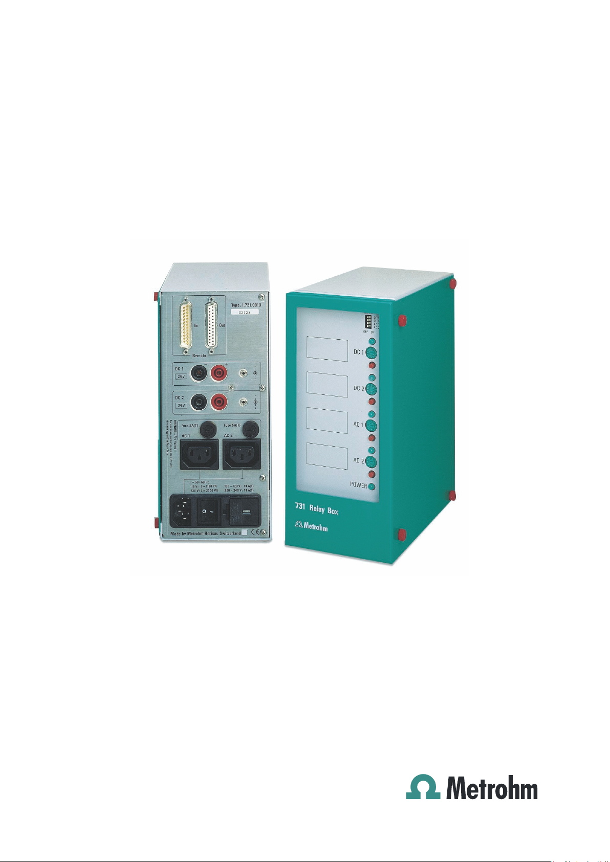
731 Relay Box
8.731.1003
Manual
05.1998 dm
Page 4

Teachware
Metrohm AG
CH-9100 Herisau
teachware@metrohm.com
This documentation is protected by copyright. All rights reserved.
Although all the information given in this documentation has been
checked with great care, errors cannot be entirely excluded. Should you
notice any mistakes please send us your comments using the address
given above.
Documentation in additional languages can be found on
http://documents.metrohm.com.
Page 5

Contents
1 Overview _____________________________________________1
1.1 Range of applications ________________________________ 1
1.2 Possible applications_________________________________ 1
1.3 Instrument description________________________________ 2
1.3.1 Front view.................................................................................... 2
1.3.2 Rear view.....................................................................................3
2 Installation___________________________________________ 4
2.1 Instrument setup_____________________________________ 4
2.1.1 Line supply.................................................................................. 4
2.2 Safety information ___________________________________ 7
2.3 Setting the DC output voltage__________________________ 9
2.4 Connections _______________________________________ 10
2.4.1 Remote control via remote lines................................................10
2.4.2 The Metrohm remote socket..................................................... 11
2.4.3 The 731 Relay Box and remote lines.........................................13
2.4.4 Connection cable......................................................................13
2.4.5 Application examples ............................................................... 15
3 Settings _____________________________________________21
3.1 Possible settings ___________________________________ 21
3.2 Inverting___________________________________________ 22
4 Technical specifications ___________________________23
5 Warranty and certificates __________________________25
5.1 Warranty __________________________________________ 25
5.2 EC Declaration of Conformity _________________________ 26
5.3 Certificate for conformity and system validation _________ 27
6 Accessories _________________________________________28
7 Index ________________________________________________29
Relay box 731, Instructions for use
Page 6

Page 7

1 Overview
1.1 Range of applications
The Metrohm 731 Relay Box is a versatile auxiliary instrument which
can be used in may different ways for switching various peripheral
devices in complex automated systems. It has been designed
specially for factory and laboratory use and makes a wide range of
applications possible. Together with a control instrument that is able
to set parallel remote lines, the 731 Relay Box allows the individual
switching of instruments that have no communication interfaces of
their own.
1.1 Range of applications
Thanks to the adjustable output level of the low-voltage direct
current outputs a wide range of instruments can be powered and
switched.
This means that you are able to assemble your laboratory
automation system according to your specific requirements.
1.2 Possible applications
The 731 Relay Box can be controlled by any Metrohm instrument (or
by an instrument from other manufacturers) that possesses a remote
output whose output lines (TTL level, 5 volt) can be set freely (e. g.
726 Titroprocessor, 730 Sample Changer, 711 Liquino) or which can
be set so that they are automatically event-controlled during a
method run (e.g. Titrinos, Metrohm pH meters).
Via the 230/110 volt current sockets (AC1 and AC2), instruments
such as pumps, heaters, coolers can be supplied with electricity.
Instruments that require a direct current supply voltage of between 5
and 24 volts or that can be controlled by voltage pulses, e.g. pumps
or Dosimats, can be connected to the low voltage direct current
outputs (DC1 and DC2).
Relay box 731, Instructions for use
1
Page 8
1. Overview
DC2
1.3 Instrument description
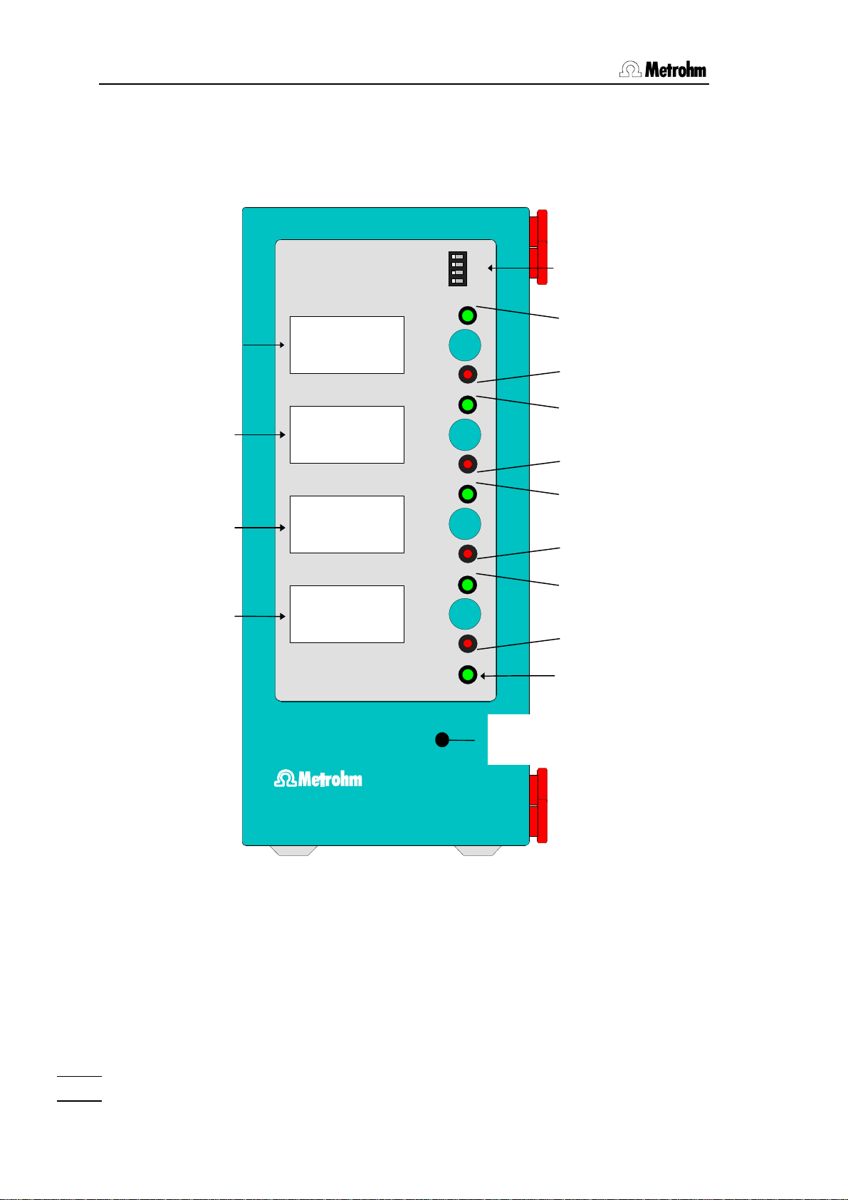
1.3.1 Front view
INVERT
OFF ON
DC 1
DC 2
AC 1
AC 2
Inverter switches
(dip switches)
Fields for magnetic
marking labels
731 Relay Box
DC 1
DC 2
AC 1
AC 2
POWER
Operating elements
direct current output
DC1
Operating elements
direct current output
Operating elements
line output AC1
Operating elements
line output AC2
Instrument status
(LED)
Removable protective
cover
2
Relay box 731, Instructions for use
Page 9
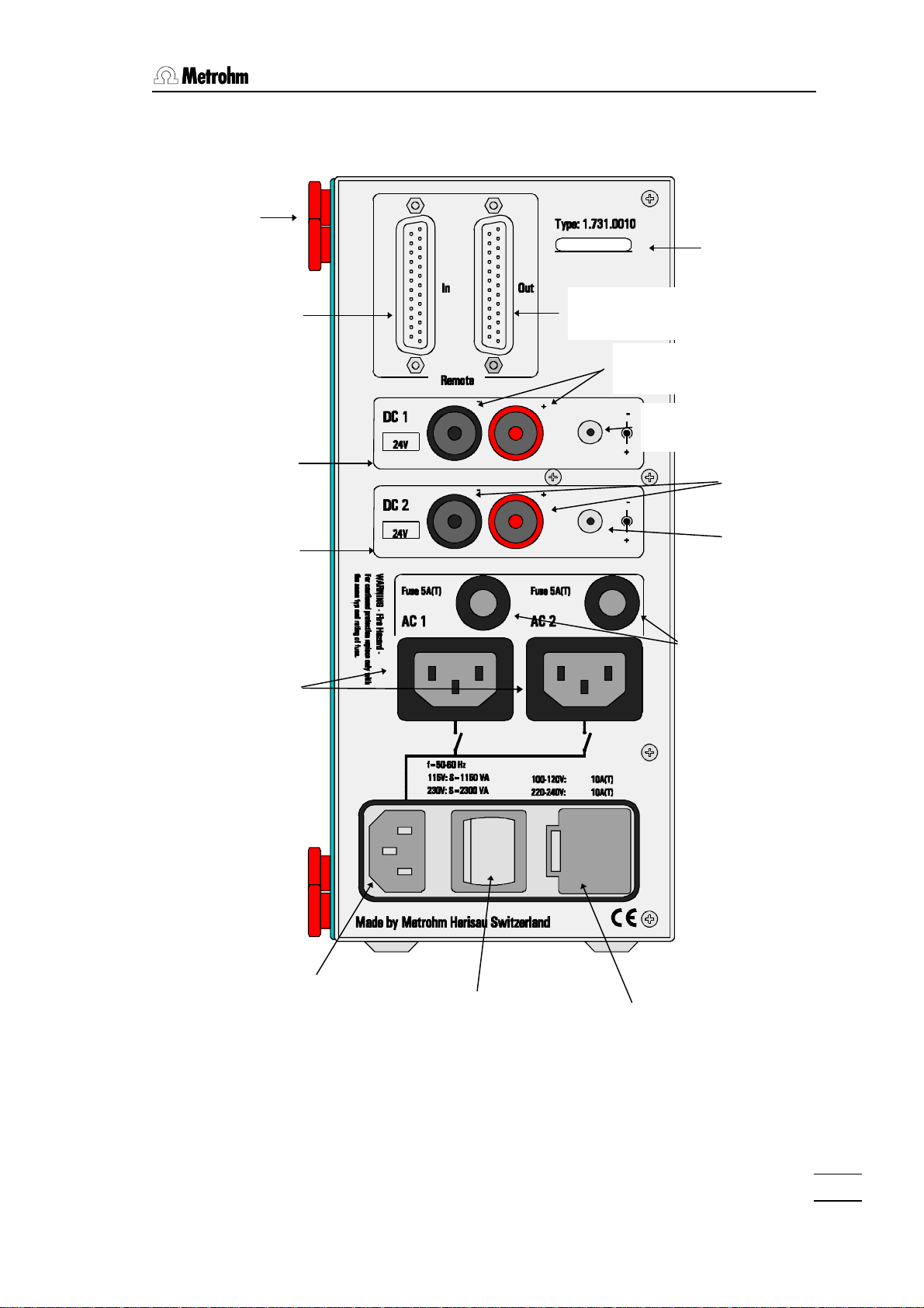
1.3.2 Rear view
Fixing screws for
protective cover
1.3 Range of applications
Identification
plate
Remote connection
IN (input)
Direct current output
DC1
Direct current output
DC2
Line voltage
outputs
AC1 and AC2
Remote connection
Out (output)
Banana
sockets DC1
Jack socket
DC1
Banana
sockets DC2
Jack socket
DC2
Fuse holders
AC1 and AC2
(line voltage
outputs)
Line connector
Relay box 731, Instructions for use
Line switch
Fuse holder (main fuse)
and voltage selector
3
Page 10
2. Installation
2 Installation
2.1 Instrument setup
Packaging
The 731 Relay Box is supplied together with the specially packed
accessories in packaging containing shock-absorbing foam which
provides excellent protection. Please store this packaging as it guarantees damage-free transport of the instrument.
Checks
Please check immediately on receipt whether the shipment is complete and undamaged (compare with delivery note and list of accessories in section 6). If transport damage is established please refer
to section 5.1 'Warranty'.
Location
The 731 Relay Box is a robust instrument and can therefore be used
even in rough conditions in factories and laboratories.
However, care should be taken that it is not exposed to a corrosive
atmosphere. Regular care of the instrument is essential if it is used
in rough surroundings.
If an instrument that has been stored at low temperatures is brought
into a heated room then the atmospheric humidity may cause water
to condense inside the instrument. In order to avoid damage to the
instrument, at least one hour should be allowed to elapse before it is
switched on.
2.1.1 Line supply
Follow the instructions given below for connection to the line supply.
If the instrument is operated with the line voltage incorrectly set
and/or the wrong line fuse there is a fire hazard!
Setting the line voltage
Before switching on the 731 Relay Box for the first time check that
the line voltage set on the instrument (see diagram on following
4
Relay Box 731, Instructions for use
Page 11
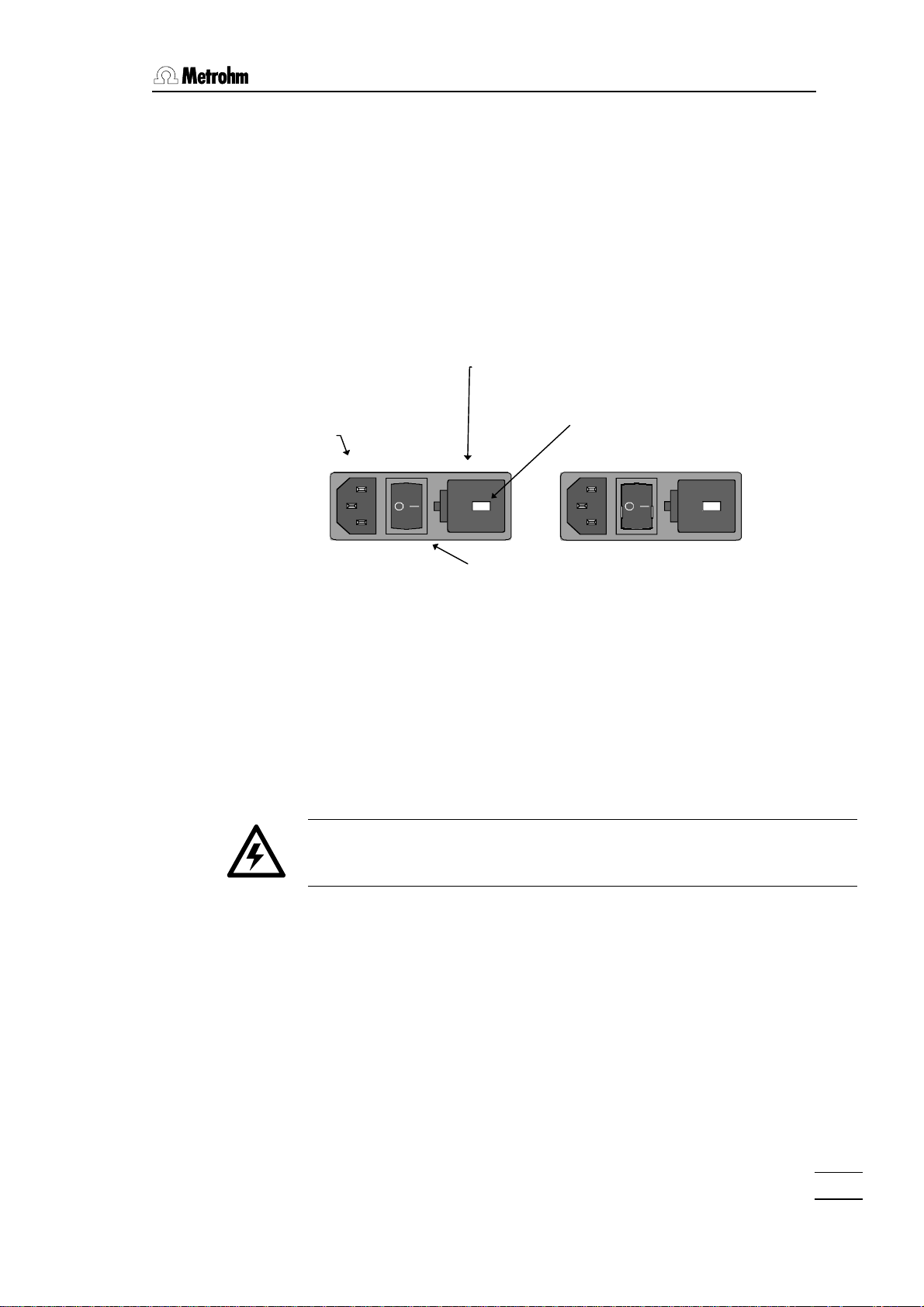
page) corresponds to the local line voltage. If this is not the case
230
115
then the correct line voltage must be set as follows:
Pull out line cable
Remove fuse holder
Line connector
2.1 Instrument setup
• Pull the line cable out of the line connector of the
731 Relay Box.
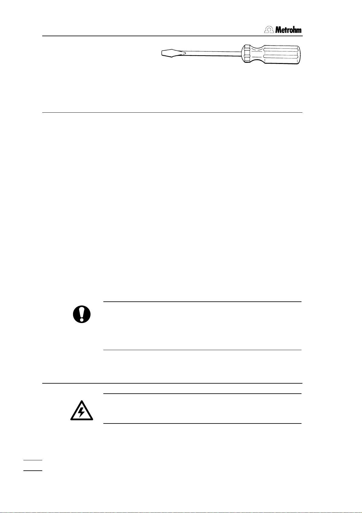
• Use a screwdriver to loosen the fuse holder beside the line
connector and pull it out completely.
Fuse holder
(main fuse)
Voltage selection insert with
voltage display
Line switch
Checking and replacing the main fuse
• Carefully remove the fuse from the fuse holder and check its
specifications:
220…250 V 10A (slow-blow) Metrohm no. U.600.0026
• Exchange the fuse if necessary and reinsert it in the fuse
holder.
Make sure that the instrument is never operated with any other type of
fuse as otherwise there is a fire hazard!
Change line voltage
• Carefully remove the voltage selector insert with the help of a
screwdriver and rotate it. Replace the insert so that the required
voltage is visible in the fuse holder window.
Relay Box 731, Instructions for use
Replace fuse holder
• Insert the fuse holder and click it into position by pressing it down
strongly with a finger.
5
Page 12

2. Installation
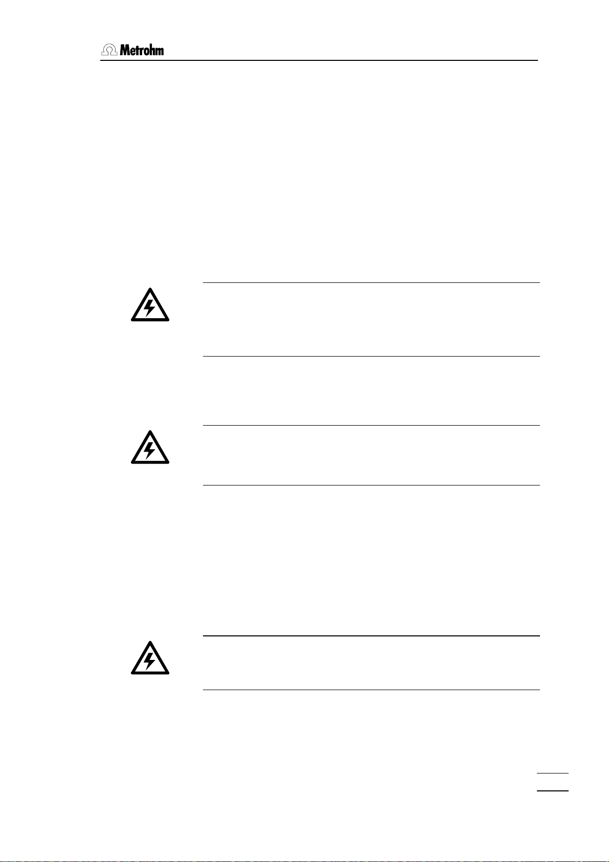
Checking and replacing the AC fuses
Line voltage outputs AC1 and AC2 have their own fuses.
Fuse 5A(T)
Fuse holder AC1
AC 1
• Use a screwdriver to press down strongly the affected fuse holder
and turn it counterclockwise through 90°. Carefully remove the
fuse holder.
• Carefully remove the fuse from the fuse holder and check its
specifications:
220…250 V 5A (slow-blow) Metrohm no. U.600.0023
Please note that the specification of this fuse is different from
that of the main fuse!
• Replace the fuse if necessary and insert it in the fuse holder
again.
6
Relay Box 731, Instructions for use
Page 13
2.2 Safety information
General:
This instrument left our factory in perfect condition from a safety
consideration point of view (see Technical specifications, Safety
specification). To maintain this condition and for danger-free instrument operation the following instructions should be carefully observed.
Line connection:
The line cables supplied with the instrument have three leads and
are fitted with a plug having an earthing pin. If a different plug has to
be used then the yellow/green lead should be connected to earth.
WARNING!
Any break in the earthing lead, whether inside or outside the instrument, represents a potential hazard to the operator. Making a break
in the earthing lead is forbidden.
2.2 Safety information
Before the plug is connected to the line a check must be made to
ensure that the instrument is set to the local line supply voltage and
that the appropriate fuses are inserted.
WARNING!
When exchanging a fuse and when setting a different line voltage
the mains cable must be disconnected from the line supply.
Repair and maintenance:
If errors or malfunctions occur during the operation of the 731 Relay
Box then it is recommended that the cable connections with the peripheral devices are checked first for proper functioning (see page
15ff).
If it is absolutely necessary to open the instrument then the following
safety measures must be observed at all cost:
The instrument must be separated from all voltage
sources before it is opened. Make sure that the line
connector has been pulled out.
Relay Box 731, Instructions for use
Condensers inside the instrument may still be charged even when
the instrument is no longer connected to the line supply.
Manipulations on an opened instrument that is connected to the line
supply should only be carried out by an expert who is familiar with
the dangers that this involves.
7
Page 14

2. Installation
When replacing fuses care must be taken that the voltage, amperage and type have been correctly selected (see Technical specifications, Fuses, page 23).
WARNING!
Short-circuiting fuses or the temporary use of incorrect fuses is forbidden.
Static electricity:
The circuits contain components that may be destroyed by electrostatic charges or whose functions may be affected by them. Work on
open instruments should only be carried out in ESD-protected surroundings.
Suitable measures:
1. Conducting mat on the work surface which is connected to the
protective earth via a resistance of approx. 1 megaohm.
2. Earthed soldering bits.
3. The wrists of persons working with components must be earthed
by connection to the protective earth via a resistance of approx. 1
megaohm.
4. Components and assembled PCBs should only be stored and
transported in conductive packaging or foam.
5. New components should be stored in their original packaging
until required.
If it becomes apparent that the instrument can no longer be operated safely then it should not be used at all.
8
Relay Box 731, Instructions for use
Page 15

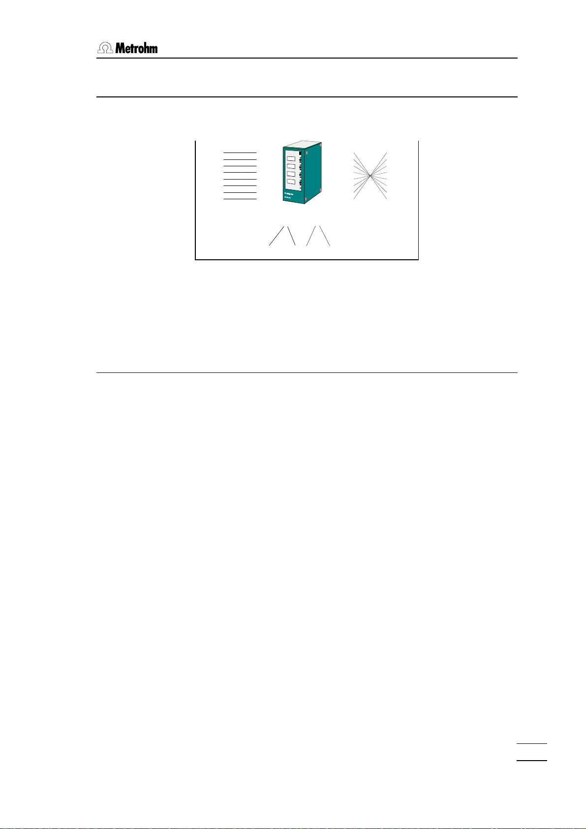
2.3 Setting the DC output voltage
The common output voltage for the direct current outputs (DC1 and
DC2) is set inside the Relay Box housing.
• Switch off the instrument and pull out the line plug. Loosen the
four knurled screws of the protective cover and remove them.
2.3 Setting the DC output voltage
Right-hand side
of housing without protective
Rear view of
housing without
protective cover
cover
• The screws marked with an arrow in the diagram must be loos-
ened.
• Carefully remove the instrument PCB from the housing.
To set the output voltage the plug-in bridge P9 on the relay box
motherboard must be fitted with the appropriate jumper .
The location of plug-in bridge P9 can be seen in the diagram of the
instrument motherboard shown below.
Set the jumper, which is located in the +24 V position
as standard, to the position corresponding to the required output voltage with the help of tweezers or ta-
P9
1 12
+10V
+18V
+24V
0V*
+5V
6 7
per-nose pliers.
P9
1 12
Relay Box 731, Instructions for use
+10V
+18V
+24V
0V*
+5V
7
6
Jumper
Carefully reinsert the motherboard in the housing and screw the instrument together. Use the adhesive labels provided to note the set
output voltage on the rear panel of the instrument.
9
Page 16

2. Installation
2.4 Connections
Metrohm automated systems with the 731 Relay Box
730
730 Sample Changer
691
692
712
713
pH Meter /
Conductometer
711 Liquino
Remote
Out
Remote
In
AC1
AC2
Titrino family
731 Relay Box
DC1
DC2
702
716
718
719
720
736
751
758
726 Titroprocessor
726
717
717 Sample Changer
665
715
725
765
Dosimat
775
776
Pumps
Heaters
...
2.4.1 Remote control via remote lines
Remote control of instruments within a Metrohm automated system
can (apart from data communication via RS232 connections) be
carried out in a simple manner with the help of parallel-switched signal leads, the remote lines (or I/O lines). Signals can be set statically
or transmitted as a signal pulse (usually approx. 200 ms long). The
signal level is +5 volt (TTL level) in each case.
Most Metrohm instruments are fitted with a remote connection. This
is normally a 25-pin socket. Different connection cables are available
for different types of instrument. The suitable remote cable is listed in
the ‘Instructions for use’ of the corresponding instrument. Special
connection cables can also be made according to information supplied by the customer.
10
772 Pump Unit
other
devices
Valves
Relay Box 731, Instructions for use
Page 17

2.4.2 The Metrohm remote socket
Particular instrument functions can be triggered by activating the individual pins (connection pins) of a remote socket. The instrument
itself activates certain pins according to the instrument’s condition
and transmits signal pulses when particular events occur.
The functions which are used for remote control in an automated
system are allocated to logical remote lines. They are subdivided
into input lines (signal inputs to trigger functions, e. g. START or
STOP) and output lines (signal outputs to display the instrument’s
condition or events, e. g. 'ready' or 'End of Determination' =EOD).
The pin assignation of a 25-pin remote plug can be seen from the
information given below.
2.4 Connections
0 Volt
+5 Volt
Output 5
Output 3
Output 1
Output 12
Output 13
Input 0
Input 2
Input 4
Input 6
0 Volt
Remote plug
(with 25 pins)
Output 6
Output 7
Output 4
Output 2
Output 0
Output 8
Output 9
Output 10
Input 1
Input 3
Input 5
Input 7
Output 11
+5V
InputsInputs
active = low
inactive = high
OutputsOutputs
active = low
inactive = high
Electrical switching of the inputs
and outputs of the remote socket
Standard allocation of the remote lines in Metrohm instruments:
Remote lines Pin Function
Input 0 21 Start
Input 1 9 Stop
Input 2 22 Enter
Input 3 10 Clear
Input 4 23 Sample Ready
Input 5 11 not used
Input 6 24 not used
Input 7 12 not used
Output 0 5 Ready
Output 1 18 Conditioning ok
Output 2 4 Determination busy
Output 3 17 EOD (End of Determination)
Output 4 3 L1
Output 5 16 Error
Output 6 1 Activate L3
Output 7 2 Pulse for recorder
Relay Box 731, Instructions for use
Output lines 8…13 are normally not used as standard.
11
Page 18

2. Installation
Assignation of the remote socket according to pins:
Pin I/O lead Function
1 Output 6 L3 activate
2 Output 7 Pulse for recorder
3 Output 4 L1
4 Output 2 Determination busy
5 Output 0 Ready
6 Output 8
7 Output 9
8 Output 10
not used
not used
not used
9 Input 1 Stop
10 Input 3 Clear
11 Input 5
12 Input 7
13 Output 11
not used
not used
not used
14 0 Volt
15 +5 Volt
16 Output 5 Error
17 Output 3 EOD (End of Determination)
18 Output 1 Conditioning ok
19 Output 12
20 Output 13
not used
not used
21 Input 0 Start
22 Input 2 Enter
23 Input 4 Sample Ready
24 Input 6
not used
25 0 Volt
12
The pin assignation or the allocation of functions of the remote lines
may differ slightly from one Metrohm instrument to another. Consult
the ‘Instructions for use’ of your instrument.
Relay Box 731, Instructions for use
Page 19
2.4.3 The 731 Relay Box and remote lines
Linear 1:1 cable Remote cable
6.2125.100 e. g. 6.2141.020 e.g. 6.2141.020
2.4 Connections
One instrument
(Master) sets output
lines via remote
socket
Output 0
Output 1
Output 2
...
...
Input 2
Input 1
Input 0
The Relax Box 731 scans the output lines and switches
the outputs AC1, AC2, DC1, DC2 accordingly.
The signals of the remote lines are transmitted to an
additional instrument connected to the 'Remote Out'
socket.
2.4.4 Connection cable
Remote In
Cable 6.2125.100 is required to control the 731 Relay Box. This cable leads the output lines (Output 0…14) linearly (i.e. pin to pin) to
the remote input (Remote In) of the 731 Relay Box, which interprets
(scans) the remote lines and switches the defined outputs accordingly.
Remote
In
AC1
AC2
DC1
DC2
Remote
Out
Output 0
Output 1
Output 2
:::
...
Input 2
Input 1
Input 0
One instrument receives input signals
via remote socket.
The remote signals
are not influenced by
the 731 Relay Box.
Relay Box 731, Instructions for use
Remote Out
The remote lines pass through the instrument linearly and can be
further used at the 'Remote Out' socket. The normal remote cable
can be used here for connection to other instruments. In Metrohm
remote cables the different remote leads are wired crosswise in order to make the bi-directional remote control of instruments possible. The pins of the logical output lines of plug A are connected to
the corresponding pins of the input lines of plug B and vice versa.
13
Page 20

2. Installation
Linear 1:1 6.2125.100 cable (25-pin)
Output 0 (Pin 5) (Pin 5) Output 0
Output 1 (Pin 18) (Pin 18) Output 1
... ...
Input 0 (Pin 21) (Pin 21) Input 0
Input 1 (Pin 9) (Pin 9) Input 1
… …
0 V (Pin 14) 0 V (Pin 14)
0 V (Pin 25) 0 V (Pin 25)
+5 Volt (Pin 15) +5 Volt (Pin 15)
Remote cable e.g. 6.2141.020 (25-pin)
Output 0 (Pin 5) (Pin 21) Input 0
Output 1 (Pin 18) (Pin 9) Input 1
Output 2 (Pin 4) (Pin 22) Input 2
Output 3 (Pin 17) (Pin 10) Input 3
Output 4 (Pin 3) (Pin 23) Input 4
Output 5 (Pin 16) (Pin 11) Input 5
Output 6 (Pin 1) (Pin 24) Input 6
Output 7 (Pin 2) (Pin 12) Input 7
Output 8 (Pin 6) (Pin 6)
Output 9 (Pin 7) (Pin 7)
Output 10 (Pin 8) (Pin 8)
Output 11 (Pin 13) (Pin 13)
Output 12 (Pin 19) (Pin 19)
Output 13 (Pin 20) (Pin 20)
Input 0 (Pin 21) (Pin 5) Output 0
Input 1 (Pin 9) (Pin 18) Output 1
Input 2 (Pin 22) (Pin 4) Output 2
Input 3 (Pin 10) (Pin 17) Output 3
Input 4 (Pin 23) (Pin 3) Output 4
Input 5 (Pin 11) (Pin 16) Output 5
Input 6 (Pin 24) (Pin 1) Output 6
Input 7 (Pin 12) (Pin 2) Output 7
(Pin 6) (Pin 6) Output 8
(Pin 7) (Pin 7) Output 9
(Pin 8) (Pin 8) Output 10
(Pin 13) (Pin 13) Output 11
(Pin 19) (Pin 19) Output 12
(Pin 20) (Pin 20) Output 13
0 V (Pin 14) 0 V (Pin 14)
0 V (Pin 25) 0 V (Pin 25)
+5 Volt (Pin 15) +5 Volt (Pin 15)
14
Relay Box 731, Instructions for use
Page 21

2.4.5 Application examples
The 731 Relay Box is controlled via remote lines which can be freely
selected in many Metrohm instruments and set to be operationcontrolled.
730/717 Sample Changer – 731 Relay Box –
772 Pump Unit
The 772 Pump Unit can be used to aspirate titration samples containing solids.
2.4 Connections
On the 731 Relay Box an output line must be
set for each switchable output; this then controls the corresponding output. This is done
with the remote address selection disk on the
front of the relay box. Use a screwdriver to set
the corresponding number of the output line.
See also page 21.
e.g. Titrino
(cable 6.2141.020)
731
730
772
cable 6.2125.100
Settings for the 731 Relay Box:
Connected to DC1 (or DC2)
Output voltage: 18 or 24 volt
Remote address selection disk DC1: D (=Output 13)
730 Sample Changer, control commands:
CTL:Rm : 1************* switches pump on (Output 13)
CTL:Rm : 0************* switches pump off (Output 13)
Relay Box 731, Instructions for use
The output lead can be selected freely. Avoid conflicts with other instruments which may be connected, e.g. Titrinos (output lines occupied: Output 0…7).
15
Page 22

2. Installation
726 Titroprocessor – 731 Relay Box –
2x hotplates/stirrers
Control of hotplates/stirrers for titrations with the 726 Titroprocessor.
6.2125.100 cable
731
726
Dosinos
Settings for the 731 Relay Box:
Connected to AC1 and AC2 (line voltage)
Remote address selection disk AC1: 6 (=Output 6)
Remote address selection disk AC2: 7 (=Output 7)
726 Titroprocessor, control commands:
Switching on the hotplates/stirrers:
CTRL_RM Remote A Signals 1*******
CTRL_RM Remote A Signals *1******
Switching off both hotplates/stirrers:
CTRL_RM Remote A Signals 00******
The output lead can be selected freely. Avoid conflicts with other instruments which may be connected.
711 Liquino – 731 Relay Box – 772 Pump Unit –
Thermostat
Liquid handling setup with 772 Pump Unit as delivery or aspirating
pump and a thermostatic bath.
6.2125.100 cable
711
731
772
Thermostatic bath
Dosinos
16
Relay Box 731, Instructions for use
Page 23
2.4 Connections
6.2125.100 cable
Settings for the 731 Relay Box:
772 Pump Unit connected to DC1 (or DC2)
Output voltage: 18 or 24 volt
Remote address selection disk DC1: 7 (=Output 7)
Thermostatic bath connected to AC1 (or AC2, line supply)
Remote address selection disk AC1: 6 (=Output 6)
711 Liquino, control commands:
SEQ mode
Switch on pump:
Command: CONTROL
Interface: Remote
Signals 1***---- (Output 7)
(switch off with 0***----)
Switch on thermostatic bath:
Command: CONTROL
Interface: Remote
Signals *1**---- (Output 6)
(switch off with *0**----)
The output lead can be selected freely. Avoid conflicts with other instruments which may be connected.
751 Titrino with 700 Dosino – 731 Relay Box –
772 Pump Unit
The 772 Pump Unit can be used aspirate the contents of a titration
vessel.
731
751
772
Settings for the 731 Relay Box:
Relay Box 731, Instructions for use
772 Pump Unit connected to DC1 (or DC2)
Output voltage: 18 or 24 volt
Remote address selection disk DC1: 4 (=Output 4)
17
Page 24
2. Installation
751 Titrino , control commands:
TIP mode
Switch on pump:
>sequence
x.step output L4
x.output L4: active
Switch off pump:
>sequence
y.step output L4
y.output L4: inactive
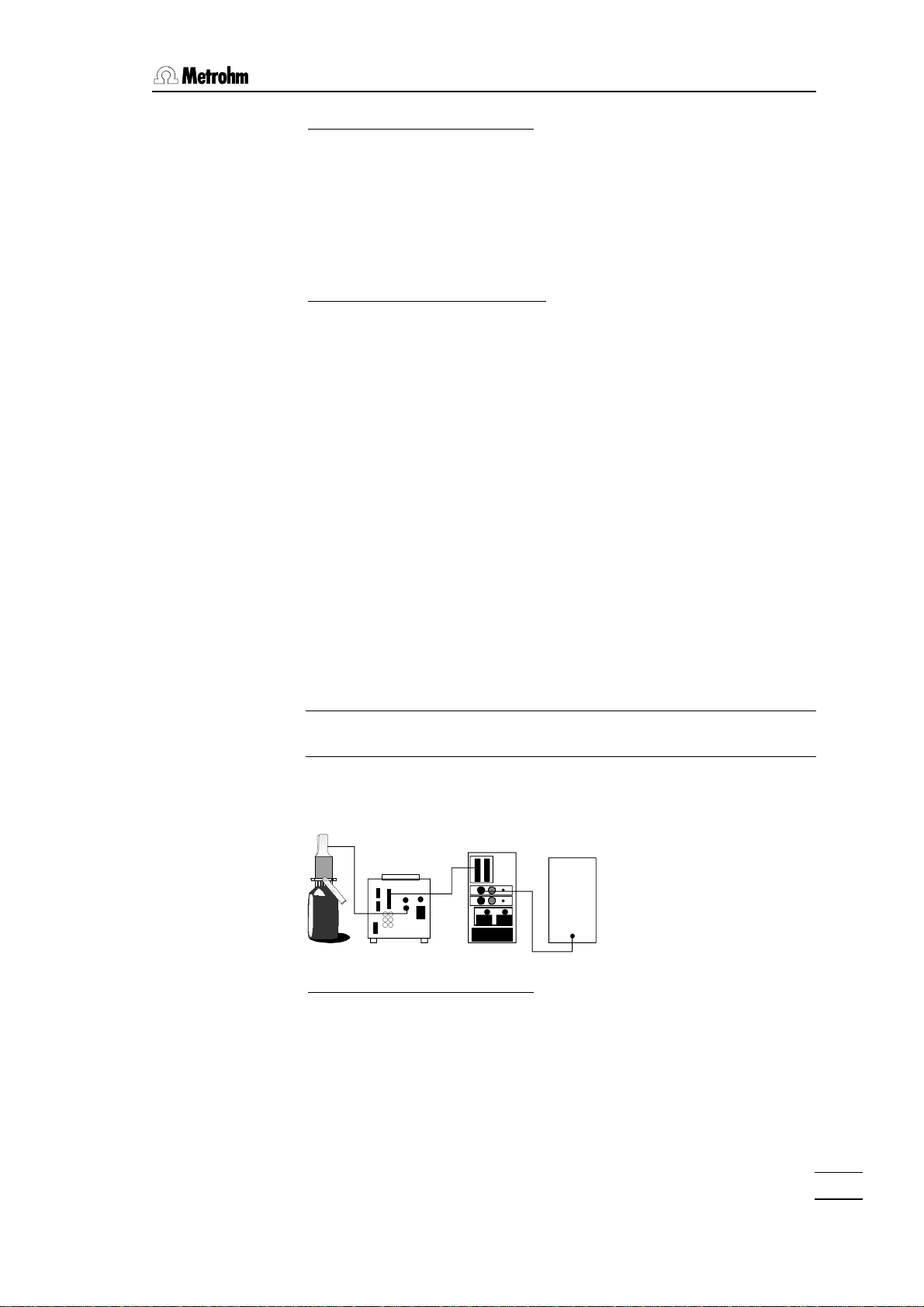
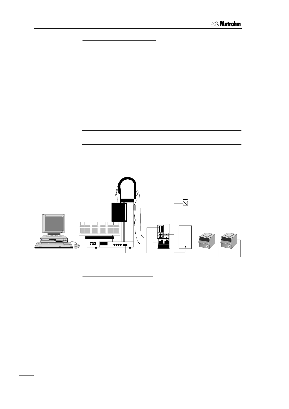
PC-controlled titration system with the 731 Relay Box
– 772 Pump Unit – aeration valve – 2 x Titrino
For determinations under an inert gas atmosphere an aeration valve
can be switched on and off. In larger analytical systems instruments
can be switched on and off selectively.
Solenoid valve
6.2726.080
731
772
6.2125.100 cable
Settings for the 731 Relay Box:
Aeration valve connected to DC1
Output voltage: 24 volt
Remote address selection disk DC1: D (=Output 13)
772 Pump Unit connected to DC2
Output voltage: 24 volt
Remote address selection disk DC2: C (=Output 12)
Titrinos connected to AC1 and AC2 (line voltage)
Remote address selection disk AC1: B (=Output 11)
Remote address selection disk AC2: B (=Output 11)
Titrinos
18
In this way both Titrinos are switched on or off at the same time.
Relay Box 731, Instructions for use
Page 25

Control commands in Tinet 2.x:
In a sequence for 730 Sample Changer
Switch on aeration valve:
Switch off with bit pattern: 0*************
Switch 772 Pump Unit:
2.4 Connections
Bit pattern: *1************ (=on)
Bit pattern: *0************ (=off)
Switch Titrinos:
Bit pattern: **1*********** (=on)
Bit pattern: **0*********** (=off)
The output line can be selected freely. Avoid conflicts with other instruments which may be connected.
... – 731 Relay Box – 665, ... Dosimat
In an automated system 665, 715, 725, etc. Dosimats can also be
used as auxiliary dosing devices . If these cannot be connected directly to the control instrument (via dosing contacts) then this is possible with a 731 Relay Box via remote lines.
731
Relay Box 731, Instructions for use
665
2x 6.2106.XXX cable strand, crossed
19
Page 26

2. Installation
Settings for the 731 Relay Box:
Dosimats connected to AC1 (or AC2)
Important!
The cable strands (with banana plugs) must be connected crosswise
to the Dosimats (at the dosing contact), i.e. red plug in black socket
and vice versa.
Output voltage: 0 volt
Remote address selection disk AC1: see previous example
To set 0 volt output voltage the jumper must be set on the motherboard in the following way:
P9
1 12
The plug and socket connection between pin
+10V
+18V
+24V
0V*
+5V
7
6
1 and pin 12 must be opened.
Set jumper to 0 V position (pin 5 — 8).
Further information about setting the output voltage can be found on
page 8.
20
Relay Box 731, Instructions for use
Page 27

3 Settings
Output status (LED)
Control button
3.1 Possible settings
3.1 Possible settings
DC 1
Marking field
For each switchable output (DC1, DC2, AC1, AC2) the operating
and control items represented above are available.
• Marking field
With the 731 Relay Box two magnetic shields are provided.
Use scissors to adapt these to the desired length. Use the shields
to mark each output, e.g. with the designation of the device that
is attached to the corresponding output.
• Output status (LED)
The status indication lights up if the corresponding output is switched on.
• Remote address selection disk
With the help of a screwdriver the remote line, that is to be monitored can be selected (0=Output 0, …, A=Output 10, B=Output
11, C=Output 12, D=Output 13, E and F do not have any function). If the selected remote line (output 0... 13) is active, the corresponding output (DC1, DC2, AC1, AC2) is switched on. If the
output line is inactive the output is switched off .
Remote address selection disk
731 Relay Box, Instructions for use
If the correct output line of a certain signal is not known, you may
proceed as follows: Set the status of the sending so that the desired condition is established.Turn the remote address selector
until the status LED lights up. Maintain this adjustment.
• Control button
By pressing the control button, the corresponding output can be
switched on for a short time.
21
Page 28

3. Settings
3.2 Inverting
For each switchable output a DIP switch is available, with which
the circuit logic can be inverted.
INVERT
OFF ON
DC 1
DC 2
AC 1
AC 2
If a DIP switch is thus switched 'INVERT ON ' (to the
right) by means of a screwdriver, the appropriate
output (DC1, DC2, AC1 or AC2) is switched on if
the output line is inactive .
The relationship remote 'active' ⇒ output 'off' is
then observed, and vice versa.
The inverting circuit can also be useful to, e.g., constantly supply
an AC output (AC1, AC2) switched on, i.e. an attached device is
continuously supplied with line voltage.
To do this, set the Remote address selector AC2 (or AC1) to a
position without function (E or F) and the corresponding INVERT
DIP switch to 'ON'.
22
731 Relay Box, Instructions for use
Page 29

4 Technical specifications
Dimensions Width: 102 mm, height: 225 mm, depth: 191 mm
Weight 4.5 kg without accessories
Housing metal case, multiple stove-enamel
DC-Sockets Output voltage, adjustable 0, 5, 10, 18, 24 V
Max. load: 1 A each output
AC-Sockets Output voltage = supply voltage
Max. load: 5 A each output
Breaking capacity: 1150 VA (at 230 V) each output
Remote-Interface
Remote In D-Sub socket 25-pins
14 x Input 5V TTL or CMOS
active = low >100 ms
inactive = high
3.2 Inverting
Remote Out D-Sub socket 25-pins
14 x Output open collector < 40V < 20mA
active = low >200 ms
inactive = high
Ambient temperature
Nominal
operating range +5 ... +40 °C at 20 .. 80% atmospheric humidity
Storage, transport -40 ... +70 °C
Power supply
Voltage Voltage selector 115/230V
Settings with other supply voltages:
100 V ... 120 V --> 115 V
220 V ... 240 V --> 230 V
Tolerance ±10%
Frequency 50 … 60 Hz
Power input 115 V max 1150 VA
230 V max 2300 VA
Fuses 10 AT for 115/ 230 V (main fuse)
5 AT for 115/ 230 V (AC fuses)
731 Relay Box, Instructions for use
23
Page 30

4. Technical specifications
Safety specifications
Constructed and tested according to :
IEC 1010/EN 61010/UL 3101-1 Safety class I,
EN 60 947-1 degree of protection IP2L1.
The instruction manual contains information and warnings which
the user should follow to guarantee the safe operation of the in-
strument.
Electromagnetic Compatibility (EMC)
Emitted interference Standards met:
EN50081-1 01.92, EN55011 (class B), EN55022 (class B) and
NAMUR
Immunity to Standards met:
interference EN50082-1 01.92, IEC801-2 to IEC801-6,
EN60555-2 and NAMUR
24
731 Relay Box, Instructions for use
Page 31

5 Warranty and certificates
5.1 Warranty
The warranty regarding our products is limited to rectification free of
charge in our workshops of defects that can be proved to be due to
material, design or manufacturing faults which appear within 12
months from the day of delivery. Transport costs are chargeable to
the purchaser.
For day and night operation, the warranty is valid for 6 months.
Glass breakage in the case of electrodes or other glass parts is not
covered by the warranty. Checks which are not a result of material or
manufacturing faults are also charged during the warranty period.
For parts of outside manufacture insofar as these constitute an appreciable part of our instrument, the warranty stipulations of the
manufacturer in question apply.
With regard to the guarantee of accuracy, the technical specifications in the Instructions for Use are authoritative.
Concerning defects in material, construction or design as well as the
absence of guaranteed features, the purchaser has no rights or
claims except those mentioned above.
If damage of the packaging is evident on receipt of a consignment
or if the goods show signs of transport damage after unpacking, the
carrier must be informed immediately and a written damage report
demanded. Lack of an official damage report releases METROHM
from any liability to pay compensation.
If any instruments and parts have to be returned, the original packaging should be used if at all possible. This applies above all to instruments, electrodes, buret cylinders and PTFE pistons. The parts
must be packed in a dustproof package (for instruments the use of a
plastic bag is imperative) before embedding them in wood shavings
or similar material. If open assemblies are enclosed in the scope of
delivery that are sensitive to electromagnetic voltages (e.g. data interfaces, etc.) these must be returned in the associated original
protective packaging (e.g. conductive protective bag).
5.1 Warranty
731 Relay Box, Instructions for use
Exception: Assemblies with built-in voltage source belong in a
non-conductive protective packaging. For damage which arises as a
result of non-compliance with these instructions no warranty responsibility whatsoever will be accepted by Metrohm.
25
Page 32

5. Warranty and certificates
5.2 EC Declaration of Conformity
The METROHM AG company, Herisau, Switzerland hereby certifies,
that the instrument:
731 Relay Box
meets the requirements of EC Directives 89/336/EWG and
73/23/EWG.
Source of the specifications:
EN 50081-1 01.92 Electromagnetic compatibility, basic specifi-
cation. Emitted Interference
EN 50082-2:1995 Electromagnetic compatibility, basic specifi-
cation. Interference Immunity
Description of the instrument:
Relay unit for the power supply of 2 AC connectors and 2 DC lowvoltage connectors.
Herisau, April 14, 1998
Dr. J. Frank Ch. Buchmann
Development Manager Production and
Quality Assurance Manager
26
731 Relay Box, Instructions for use
Page 33

5.3 Certificate of Conformity and System Validation
5.3 Certificate of Conformity and System Validation
This is to certify the conformity to the standard specifications for
electrical appliances and accessories, as well as to the standard
specifications for security and to system validation issued by the
manufacturing company.
Name of commodity: 731 Relay Box
Name of manufacturer: Metrohm Ltd., Herisau,
Switzerland
Principal technical information: Voltages: 100…120,
210…240 V
Frequency: 50…60 Hz
This Metrohm instrument has been built and has undergone final
type testing according to the standards:
IEC801-2 through IEC801-6, EN55011 (class B), EN55022
(class B), EN50081-1 01.92, EN60555-2, NAMUR
— Electromagnetic compatibility
IEC1010, EN61010, UL3101-1 safety class 1, EN 60 947-1 degree of
protection IP2L1 — Security specifications
The technical specifications are documented in the instruction manual.
Metrohm Ltd. is holder of the SQS-certificate of the quality system
ISO 9001 for quality assurance in design/development, production,
installation and servicing.
Herisau, Apr. 14, 1998
Dr. J. Frank Ch. Buchmann
Development Manager Production and
Quality Assurance Manager
731 Relay Box, Instructions for use
27
Page 34

6. Accessories
6 Accessories
731 Relay Box 2.731.0010
includes the following accessories:
Cable DB25 m/m (1:1), shielded, 2 m 6.2125.100
1 Line cable with cable socket, type CEE(22), V
Cable plug to customer's specifications
Magnetic labels, 20 x100 mm, 2 x 6.2248.000
Adhesive labels, 2 x S.211.3000
Instructions for use of 731 Relay Box 8.731.1003
Options
Accessories to separate order at additional charge
type SEV 12 (Switzerland...) 6.2122.020
type CEE(7), VII (Germany...) 6.2122.040
type NEMA/ASA (USA...) 6.2122.070
Line cable, loose end D.005.0003
(freely customizable line cable for connecting
the 731 Relay Box to any instrument's line socket)
Cable strand, length 100 cm 6.2106.020
40 cm 6.2106.030
300 cm 6.2106.050
200 cm 6.2106.060
(for connecting 665, 715, 725, … Dosimats)
Remote cable, 731 —> Titrino/692/712/713 6.2141.020
Remote cable, 731 —> 2 x Titrino/692/712/713 6.2141.030
Remote cable, 731 —> 678/682/686/672 3.980.3640
More connection cables on demand.
28
731 Relay Box, Instructions for use
Page 35

7 Index
7 Index
1:1 cable ..................... 13; 14
711 Liquino ....................... 16
726 Titroprocessor ........... 16
772 Pump Unit ...... 15; 16; 17
accessories ...................... 28
AC-sockets ....................... 23
adhesive labels ................... 9
aeration valve ................... 18
automated systems .......... 10
auxiliary dosing devices ... 19
banana plugs .................... 20
cable 6.2125.100 ........ 13; 14
cable strand ................ 20; 28
certificate .......................... 27
connection cable .............. 13
connections ...................... 10
control ............................... 13
DC-sockets ....................... 23
Declaration of Conformity . 26
Dosimat ...................... 19; 28
EC Declaration .................. 26
emitted interference .......... 24
End of Determination ........ 12
errors .................................. 7
events ............................... 11
examples of applications . 15
frequency .......................... 23
front view ............................ 2
fuse ........................... 5; 7; 23
fuse holder ...................... 5; 6
hotplates ........................... 16
I/O lines ............................ 10
immunity to interference ... 24
Input ........................... 11; 12
input lines ......................... 13
installation ........................... 4
instrument condition ......... 11
Instrument description ........ 2
instrument functions ......... 11
instrument PCB .................. 9
instrument setup ................. 4
instrument status ................ 2
inverting ............................ 22
jumper .......................... 9; 20
line cables .......................... 7
line connection ................... 7
line connector ..................... 7
line supply ...................... 4; 7
line voltage ......................... 4
liquid handling .................. 16
main fuse ............................ 5
malfunctions ....................... 7
marking field ..................... 21
max. load .......................... 23
open collector ................... 23
options .............................. 28
Output ........................ 11; 12
output lines ....................... 13
output voltage .................... 9
overview .............................. 1
pin ............................... 11; 12
pin occupancy .................. 11
plug-in bridge ......................9
possible applications ..........1
possible settings ...............21
power input ........................23
power supply .....................23
protective cover ...................2
range of applications ...........1
rear view ..............................3
remote address selection ..21
remote cable ........ 13; 14; 28
remote control ...................10
Remote In ................... 13; 23
remote lines ................ 10; 11
Remote Out ................ 13; 23
remote socket ...................11
safety information ................7
safety specifications ..........24
Sample Changer ...............15
setting the DC
output voltage ................. 9
settings ..............................21
signal level .........................10
signal pulse .......................10
stirrers ................................16
technical data ....................23
thermostatic bath .............16
Tinet ...................................19
Titrino .................................17
TTL-level ............................10
voltage selector .................23
warranty .............................25
731 Relay Box, Instructions for use
29
 Loading...