

Page 1
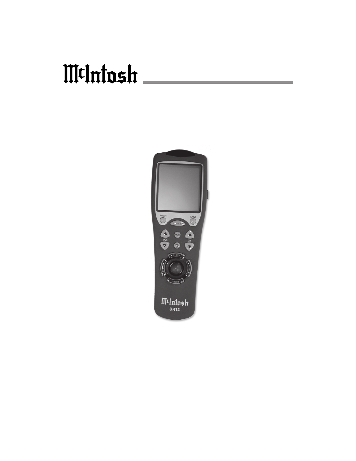
UR12 Touch Screen Remote
Owners
Manual
UR12
McIntosh Laboratory, Inc. 2 Chambers Street Binghamton, New York 13903-2699
Phone: 607-723-3512 FAX: 607-724-0549
Page 2

WARNING - TO REDUCE RISK
OF DAMAGE, DO NOT EXPOSE
THIS EQUIPMENT TO RAIN OR
MOISTURE.
NO USER-SERVICEABLE PARTS
INSIDE. REFER SERVICING TO
QUALIFIED PERSONNEL.
IMPORTANT SAFETY
INSTRUCTIONS!
PLEASE READ THEM BEFORE
OPERATING THIS EQUIPMENT.
General:
1. Read these instructions.
2. Keep these instructions.
3. Heed all warnings.
4. Follow all instructions.
5. Warning: To reduce risk of damage,
do not expose this equipment to rain
or moisture.
6. Only use attachments/accessories
specified by the manufacturer.
Installation:
7. Use in accordance with the
manufacturers instructions.
8. Do not use near any heat sources such
as radiators, heat registers, stoves, or
other equipment (including amplifiers)
that produce heat.
9. Do not use this equipment near water.
10. Do not expose this equipment to dripping or splashing and ensure that no
objects filled with liquids, are placed
on the equipment.
Care of Equipment:
11. Clean only with a dry cloth.
12. Do not permit objects or liquids of any
kind to be, spilled and/or fall onto the
equipment.
Repair of Equipment:
13. Refer all servicing to qualified service
personnel. Servicing is required when
the equipment has been damaged in
any way, liquid has been spilled or objects have fallen onto the equipment,
the equipment has been exposed to rain
or moisture, does not operate normally,
or has been dropped.
14. Do not attempt to service beyond that
described in the operating instructions.
All other service should be referred to
qualified service personnel.
15. When replacement parts are required,
be sure the service technician has used
replacement parts specified by McIntosh or have the same characteristics as
the original part. Unauthorized substitutions may result in damage other hazards.
16. Upon completion of any service or repairs to this product, ask the service
technician to perform safety checks to
determine that the product is in proper
operating condition.
2
Page 3

Thank You
Thank you for your decision to own this
McIntosh UR12 Touch Screen Remote
Control. The McIntosh dedication to
Quality, is assurance that it will provide
you with many years of enjoyment.
Please take time to read this manual, as
it will help you to become more familiar
with your new McIntosh.
Please Take A Moment
The serial number, purchase date and
dealer name are important for possible insurance claim or future service. The spaces
below have been provided to record that
information:
Note: The Serial Number is located inside
the Battery Compartment on the left
side.
Technical Assistance
If you have questions about this product,
contact your McIntosh Dealer who is more
familiar with your component system. If
additional help is needed, you can receive
technical assistance at:
McIntosh Laboratory, Inc.
2 Chambers Street
Binghamton, New York 13903
Phone: 607-723-3512
Fax: 607-723-3636
Customer Service
If your McIntosh product is in need of repair, it can returned to your dealer or the
McIntosh Service Department. For assistance on repair return procedure, contact
the McIntosh Service Department at:
Serial Number:
Purchase Date:
Dealer Name:
Copyright 2001 © by McIntosh Laboratory, Inc.
McIntosh Laboratory, Inc.
2 Chambers Street
Binghamton, New York 13903
Phone: 607-723-3515
Fax: 607-723-1917
3
Page 4

Table of Contents
Safety Instructions ................................ 2
Thank You, Please Take a Moment,
Technical Assistance and
Customer Service .................................. 3
Table of Contents and General Notes ... 4
Introduction .......................................... 5
Performance Features ........................... 5
Installing Batteries ................................ 6
Initial Start-up ....................................... 7
Touch Screen and Push-buttons ............ 8
How to Operate the Remote Control .... 9
MAC Touch Screen Pages .................. 10
System Settings
Overview ........................................................... 14
Touch Screen Contrast ....................................... 14
Entering the System Settings ............................. 14
Clock Setting ..................................................... 15
Touch Screen Alignment ................................... 15
System and Options ........................................... 15
Introduction Macro and Punch Through
Programming ..................................................... 16
Program Macro Functions ................................. 16
Device Buttons .................................................. 17
Favorite Channel Button ................................... 17
Erase Function ................................................... 17
Punch-Through Functions ................................. 17
Programming Punch-though .............................. 17
Preprogram ........................................................ 18
Auto Scan with Brand Names ........................... 19
Learning Method ............................................... 20
Erasing the Learned Buttons ............................. 21
Edit Touch-buttons ............................................ 23
Setting the Date and Clock ................................ 28
Program Loading ............................................... 28
Erasing all the Programs .................................... 29
Alternate Button Functions ................. 30
Seup Code Tables ............................... 32
Specifications and Packing ................. 44
Warranty ............................................. 45
General Notes
Caution: The UR12s LCD Screen is made
of glass and is breakable, please
handle with care.
1. The Upload Data Cable is available from
the McIntosh Parts Department:
Upload Data Cable Part No. 171-437
Six foot, 2 conductor shielded, with a
DB9 connector and one 1/8 inch stereo
mini phone plug.
2. For additional operational information,
refer to the owners manual(s) for any
component(s) that are controlled by the
UR12.
3. McIntosh Source Component(s) need to be
connected to a McIntosh Control Center via
Data Cable(s) to allow control of the
component(s) via the UR12s built-in
McIntosh Touch Screen Menus and Pushbuttons.
4. The UR12 contains Control Codes for some
of the most popular remote controlable
Audio/Video Component Products. If the
component you would like to control is not
listed in the Control Code Tables, they can
be learned by following the instructions in
the Learning Section of this manual.
5. In certain situations, the supplied Upload
Data Cable may not be long enough to
connect the UR12 to a computer. Below is
the PIN Outs of the DB9 and Stereo Mini
Phone Plug:
RS232 DB9 Connector Pin Layout
1. N/C 6. N/C
2. Data Out (TXD)In (RXD) 7. N/C
3. Data In (RXD) 8. N/C
4. N/C 9. N/C
5. Gnd.
4
Page 5
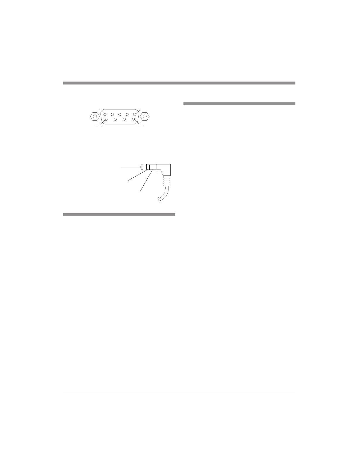
Pin 1 Pin 5
Pin 6 Pin 9
Introduction and Performance Features
Performance Features
· Controls up to Twelve Components
Features fifty LCD touch screens, 13 convenient rubber buttons and a joystick.
Stereo Mini Phone Plug
Tip - Data In (RXD)
Ring - Data Out (TXD)
Sleeve - Gnd.
Tip
Ring
Sleeve
Introduction
The McIntosh UR12 is a very powerful
and flexible learning remote control with a
LCD Touch Screen. The UR12 has many
advanced operating features that can add
convenience and enjoyment of your home
entertainment system. It is designed to operate up to twelve components. The UR12
is preprogrammed for most McIntosh Control Centers. You can program it for your
other components either from the
preprogrammed code library in the remote
control or you can teach up to 780 buttons
into the UR12 from your original remote
controls. It also allows you to change the
button size and shape and edit the text on
the button in the LCD. You can also make
these changes with the aid of your personal
computer. Setting up the UR12 to work
with your components is very easy.
· Preprogrammed for quick set up
Contains codes for most of the A/V components on the market.
· Learning Capability
Learns up to 780 commands head to head
with other remote controls.
· Customizable LCD Screens
A wide selection of button sizes and
shapes combine with the ability to write
your own text to the LCD.
· Operational Flexibility
15 programmable macro buttons, 60 programmable favorite channel buttons as
well as volume and transport punch
through operations are available.
· PC Interface
Simplifies editing and downloading programs.
· Ergonomic Design
Provides strategic button and joystick layout with backlit LCD screen.
· Memory Lock
The UR12 has an internal memory lock
system that retains all the programs and
learned functions.
5
Page 6
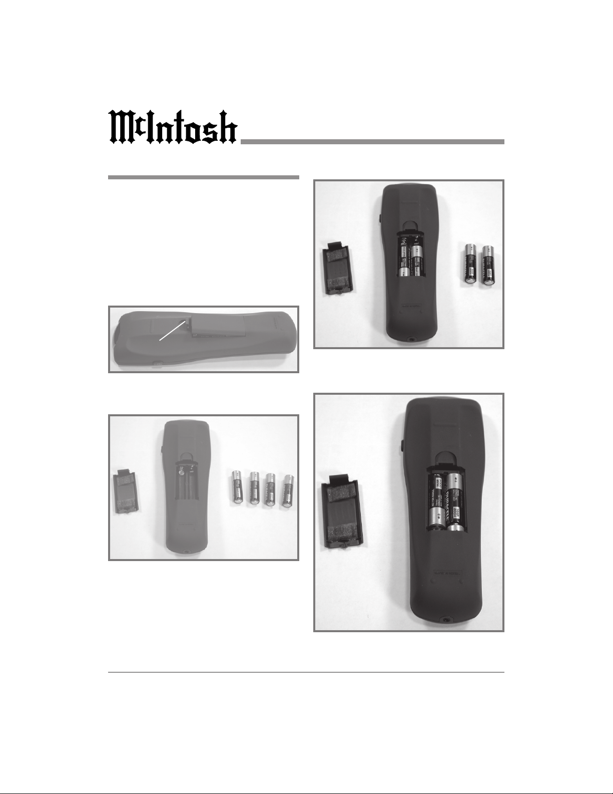
Installing Batteries
The UR12 uses four AA batteries. Please
be sure to match the batteries with the (+)
and (-) markings inside the battery compartment during installation. Refer to figures 1, 2, 3 and 4
Note: Please do not mix old batteries with
new ones or mix different types of
batteries.
Installing Batteries
Release Latch
Figure 3
Figure 1
Figure 2
Figure 4
6
Page 7
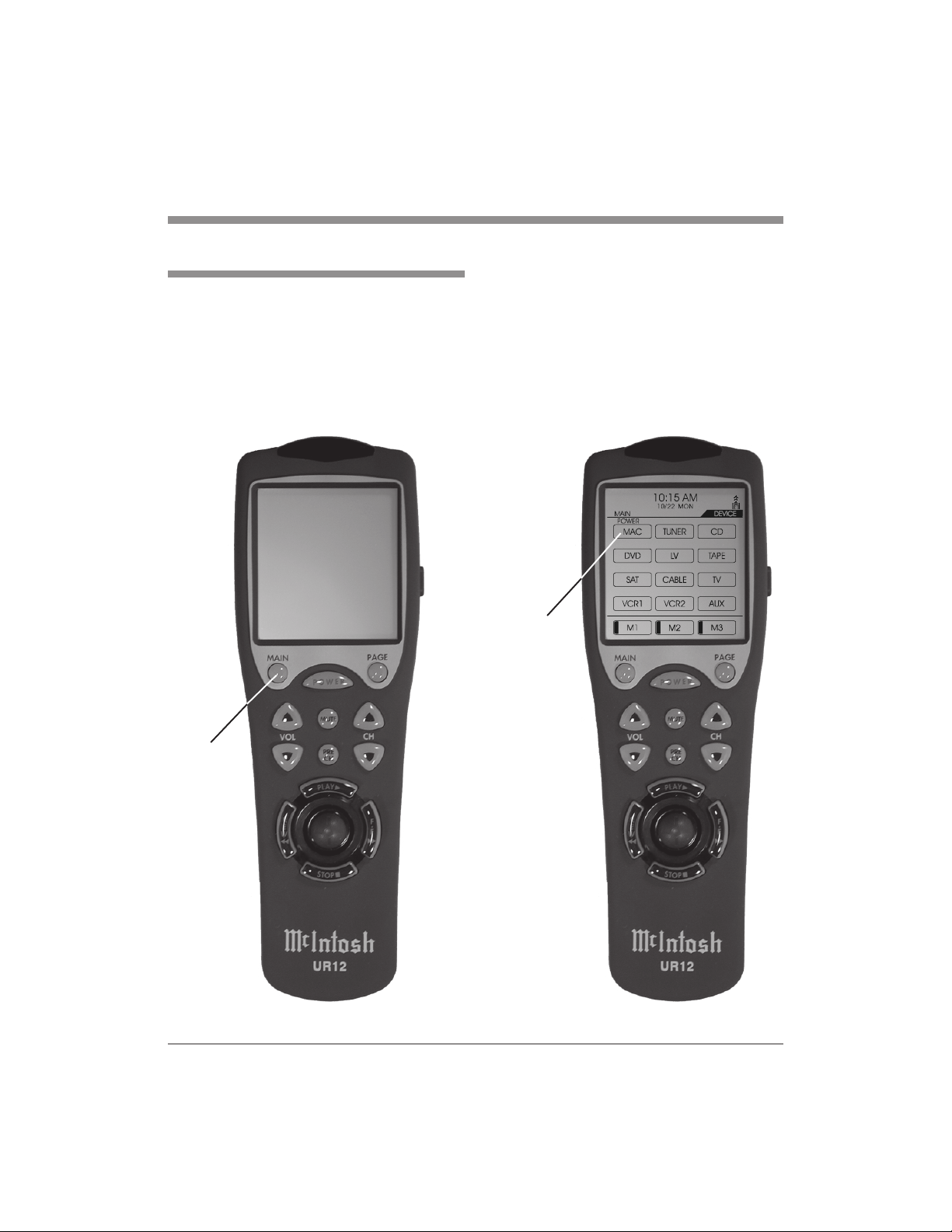
Initial Start-up
The remote control goes through self-testing for three seconds after the batteries are
installed and automatically switches to
Setting Mode for programming. Refer to
figures 5 & 6.
1. Exit the System Setting Mode by simply pressing the MAIN push-button.
SYSTEM SETTING
1. TOUCH PAD ALIGNMENT
2. SYSTEMS & OPTIONS
3. PREPROGRAM
4. LEARNING
5. EDIT BUTTONS
6. SET DATE & CLOCK
7. PROGRAM LOADING
8. TO EXIT
SELECT : JOY STICK
ENTER : JOY STICK
Initial Start-up
2. To start controlling McIntosh Components, press the MAC Touch-button on
the MAIN LCD Screen.
MAC
Touch-Button
Main
Push-button
Figure 5 Figure 6
7
Page 8
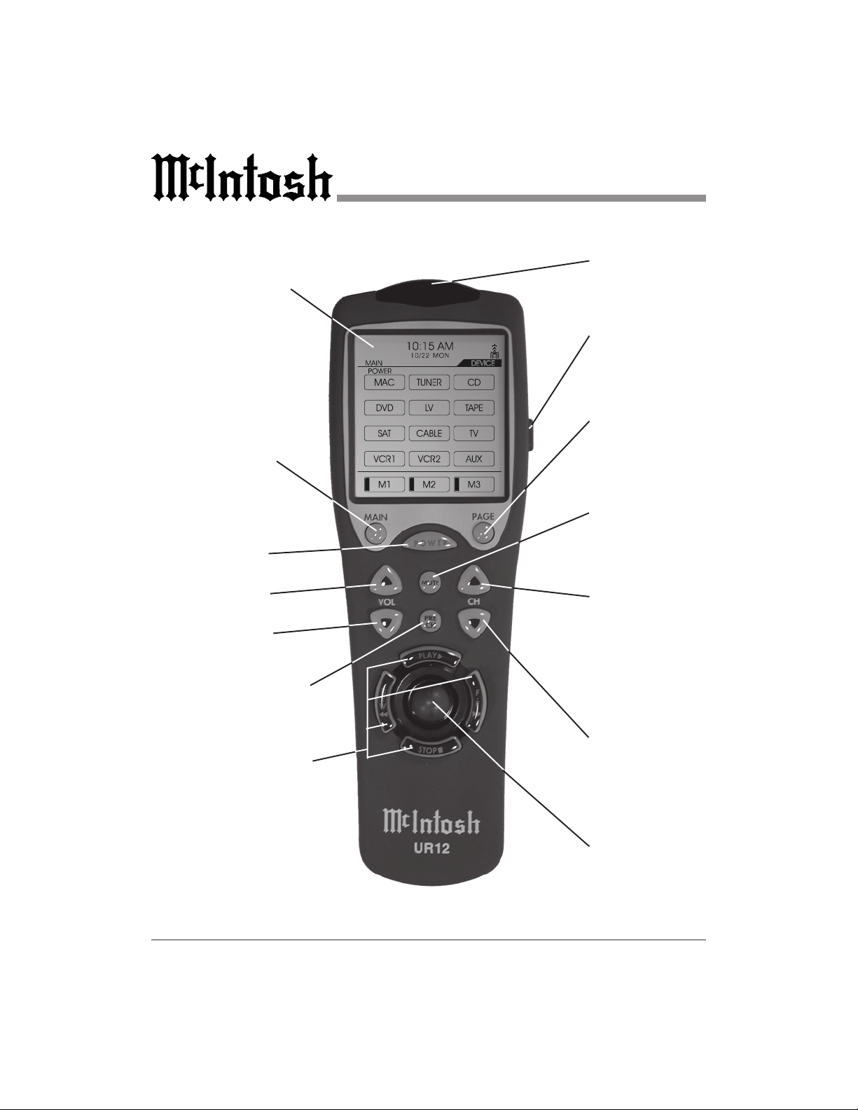
Touch Screen with
Pages of Menus
Selects the Main
Touch Screen Menu
Turns Power
ON or OFF
Adjusts the
VOLume level Up
Adjusts the
VOLume level Down
Touch Screen and Push-buttons
IR Sensor for sending and receiving
IR Signals
Press the push-button to illuminate the
Touch Screen and
Touch-buttons
Selects the different
Pages of Touch
Screen Menus
MUTEs the audio
Selects the Next
AM/FM or TV Station and the next
Selection, Track or
Chapter
Selects the
PREvious CHannel
viewed
Selects Transport
Functions of a
DVD/CD player,
DVD/CD changer
or tape recorder
8
Selects the Previous
AM/FM or TV Station and the next
Selection, Track or
Chapter
Moves the Cursor
and selects the Enter Function
Page 9

How to Operate the Remote Control
Touch Screen
The Touch Screen allows for the selection
and controlling of different components
through multiple On-Screen Pages.
Mute
Press the MUTE Push-button to mute the
audio and a second time to unmute. The
MUTE Push-button is also used in
conjuction with other push-buttons to perform programing and other functions.
Transport Functions
Use the PLAY, FAST-FOWARD
FAST REVERSE
and STOP¡ Push-
,
buttons to operate a DVD/CD player,
DVD/CD changer or tape recorder.
Channel Functions
Press and release the CHannel Up or
Down Push-button to move from station
to station on both the AM and FM Dial. In
a similar fashion, use the CHannel Up or
Down Push-button to select the next
available TV Channel. When playing a
DVD, CD or Tape the CHannel Up
Push-button will select the Next Selection, Track or Chapter and the CHannel
Down will select the Previous
(Back) Selection, Track or Chapter.
Previous Channel
When viewing TV Channels, pressing the
PREvious CHannel Push-button will select
the last TV Channel Selected.
Volume
Press the UP or DOWN VOLume
Push-button to raise or lower the listening
volume level.
Power
Switches AC Power ON or OFF for a
McIntosh Control Center or Preamplifier.
If a non-McIntosh Component is being
controlled (ie. TV), then the UR12 will
switch AC Power ON or OFF for that component.
Lighting
Press and release the LIGHT Push-button
to momentarily illuminate the Touch
Screen and the UR12 Push-buttons.
Page
Press the PAGE Push-button to select different Pages of Menus displayed on the
Touch Screen. The MAIN Push-button is
also used in conjuction with other pushbuttons to perform programming and other
functions.
Main
Press the MAIN Push-button to select the
Main Touch Screen Menu. The MAIN
Push-button is also used in conjuction with
other push-buttons to perform programming and other functions.
Joystick
The Joystick allows, the cursor to move in
four directions, selects different Touch
Screen Menu Options and the On-Screen
Menus of Source Components. By pressing the Joystick down, it also functions as
an Enter key to select the displayed function.
9
Page 10

Touch Screen Menu Page 1
Input Source Selection
Select one of the six Audio Inputs or six
Audio/Video Inputs from the available Input Sources on your McIntosh Control
Center or Preamplifier.
Note: If your McIntosh Control Center or
Preamplifier has additional Inputs
that you would like to select and
control, contact your McIntosh Dealer
for assistance.
10
Page 11
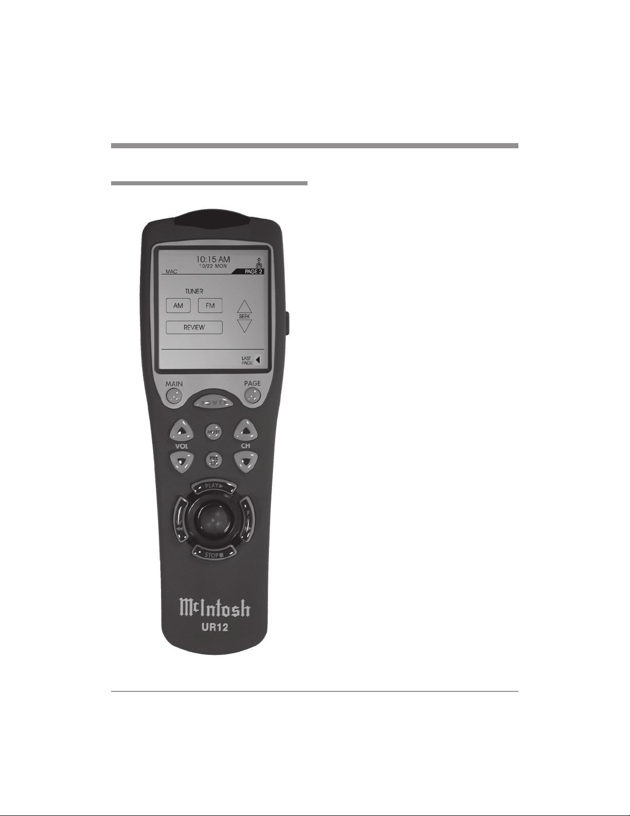
Touch Screen Menu Page 2
MAC Touch Screen Pages
Tuner Functions
Select AM or FM broadcast band. Press
and release SEEK Up or Down to move
from station to station. Press and hold a
SEEK Push-button to move continuously
from station to station. Press REVIEW to
start the automatic brief audition of each of
the presets stored in the tuner memory.
Press REVIEW a second time to stop on a
station preset and exit the Review process.
Note: The UR12s CHannel Push-buttons
may also be used to tune to the next
station. Press and release the
CHannel Up or Down Pushbutton to move from station to station
on both the AM and FM Dial.
11
Page 12
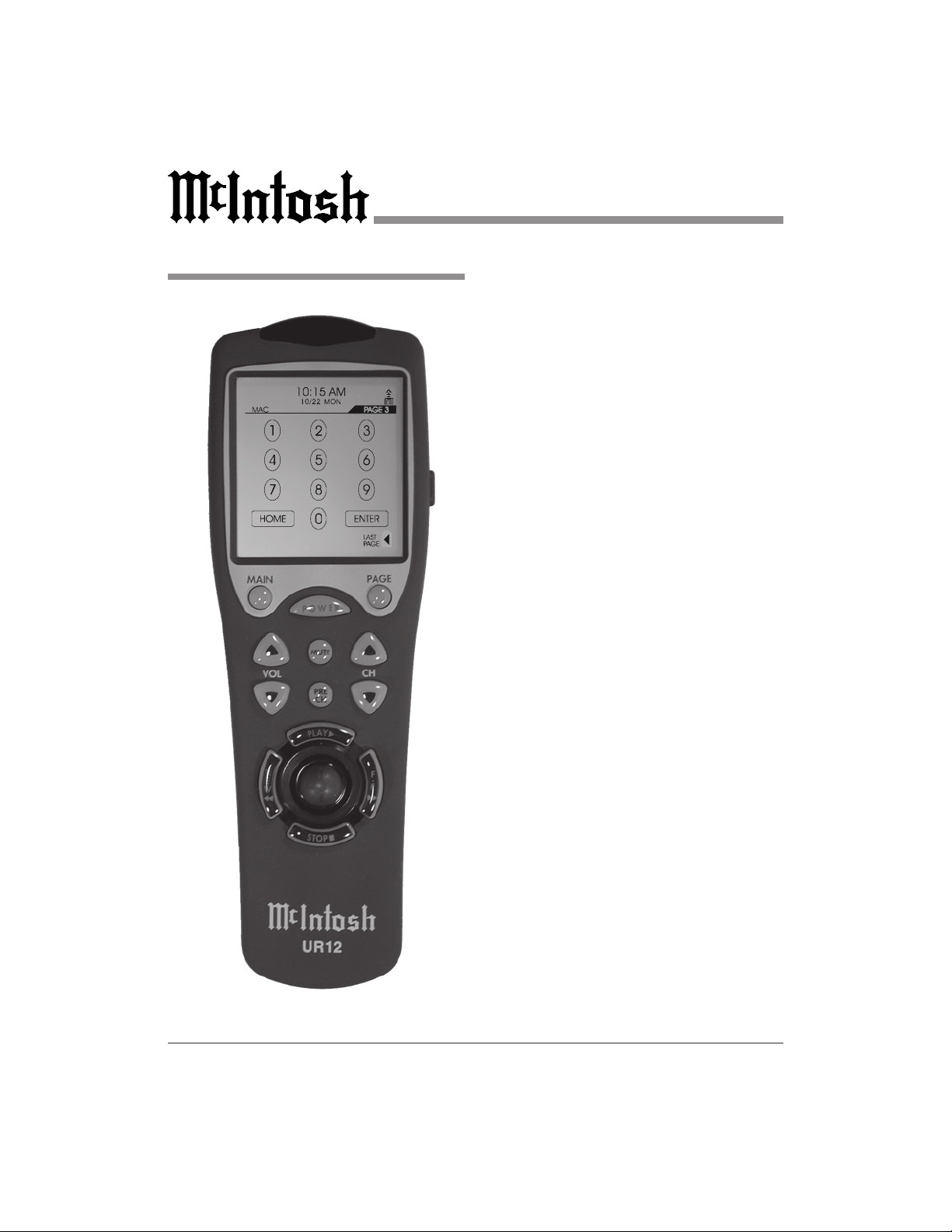
Touch Screen Menu Page 3
Numbered and +10 Push-buttons
Press push-buttons 0 through 9 to access
tuner station presets, DVD chapters, DVD/
CD tracks or DVD/CD discs. When using
a McIntosh DVD/CD player, access track
numbers higher than 10 by first pressing
+10 and then a number push-button.
Home
Allows remote operation of the McIntosh
HC-1 Home Controller, which in turn will
control power to accessories. Press the
Home Push-button and within 5 seconds,
the appropriate number Push-buttons (0
through 9) to operate the selected device.
Enter
Press ENTER to perform various functions
on a variety of McIntosh Components. It
will also pause the playing of a DVD/CD
disc or tape player.
12
Page 13

Touch Screen Menu Page 4
MAC Touch Screen Pages
Power On and Off
Switches AC Power ON or OFF.
Note: Provides discrete commands for use in
Macros.
Listen and Record Processors
Accesses the external LISTEN and/or
RECORD PROCESSOR(s) on some
McIntosh Control Centers or Preamplifiers.
Speakers 1 and 2
Switches the two pairs of SPEAKERS/
OUTPUTS On or Off.
Mode
Changes the Sound Processing Modes.
Mono/Stereo
Allows the combining of left and right signals into Mono.
System Off
Switches Off all Zones of a McIntosh System.
Level
The LEVEL Up or Down Touch-buttons
allows Trim Adjustments of various functions.
Trim
Activates the TRIM Mode and the adjustments are performed with the LEVEL
Touch-buttons. Touch TRIM a second time
to cycle through the TRIM Modes.
13
Page 14
Overview
The UR12 is designed to operate up to
twelve components. They are Control Center (labeled MAC), CATV, Satellite, TV,
DVD, VCR1, VCR2, Laser Disc, Tuner,
CD, Tape and AUX. However, the device
button name can be changed to meet your
exact needs. You can also create a favorite
device page and transfer the frequently
used devices to the favorite device page in
order to change the device button sizes and
shapes. Once you create the favorite device page, it will appear as a default device
page. There are also four pages of the LCD
screen for each device and you can use
them to create, delete or edit any functional buttons to customize with your audio/video components.
Touch Screen Contrast
The contrast of the TOUCH SCREEN can
be adjusted by pressing either the CHANNEL UP or DOWN button while holding
down the MAIN button. Release the buttons when you reach the optimal level of
contrast. Refer to figure 7.
SYSTEM SETTING
1. TOUCH PAD ALIGNMENT
2. SYSTEMS & OPTIONS
3. PREPROGRAM
4. LEARNING
5. EDIT BUTTONS
6. SET DATE & CLOCK
7. PROGRAM LOADING
8. TO EXIT
SELECT : JOY STICK
ENTER : JOY STICK
Entering the System Settings
All the programming is done by first entering the SYSTEM SETTING Mode in the
remote control. Press both the MAIN and
PAGE buttons simultaneously for five seconds to enter the SYSTEM SETTING
mode. Refer to figure 7. Move the cursor
on the screen with the joystick to your selection in the list. Enter the selection by
pushing down the joystick. You can exit
14
Figure 7
Page 15
the setting mode by simply pressing the
MAIN button or bring the cursor to 8. TO
EXIT with the joystick and push the joystick down.
System Settings
Clock Setting
Enter the Clock Setting Mode by moving
the cursor on the TOUCH SCREEN to 6.
SET DATE & CLOCK by using the joystick. Enter this mode by pushing the joystick down. Press the selection you wish to
change from the TOUCH SCREEN and
change them using the UP and DOWN
buttons. Once you complete the setting,
store them by pressing the SAVE button.
Touch Screen Alignment
Move the cursor on the TOUCH SCREEN
to 1. TOUCH PAD ALIGNMENT with the
joystick. Press the joystick down to enter
the mode. Align the screen by pressing the
three points that appear on TOUCH
SCREEN one point at a time. Follow the
On-Screen instructions.
Note: If a new version of the Normal Modes
of Operation Firmware has been
uploaded into the UR12, a Touch
Screen Aligment Procedure must be
performed inorder for the Touchbuttons to become active.
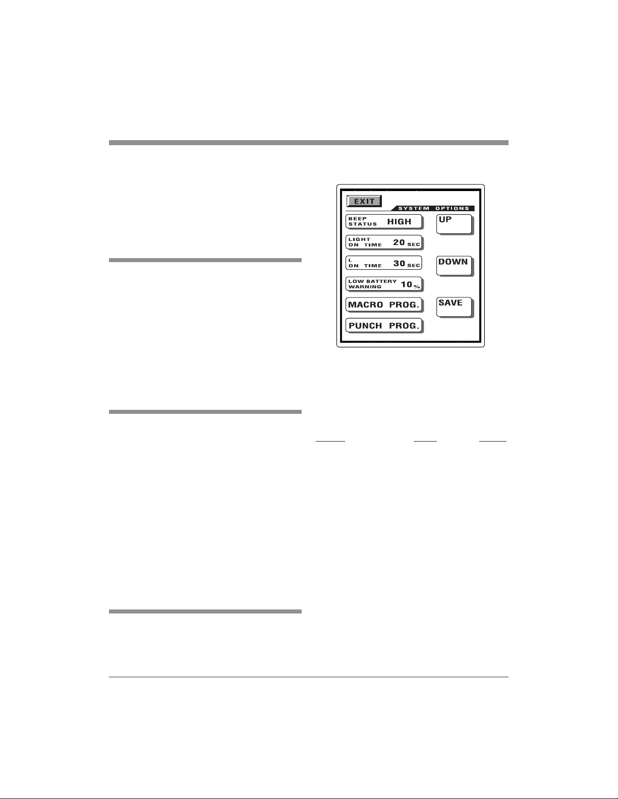
Systems and Options
Move the cursor on the TOUCH SCREEN
to 2. SYSTEM & OPTIONS with the joystick. Enter this mode by pushing the joy-
C D
Figure 9
stick down and the following can be set.
Refer to figure 9.
The TOUCH SCREEN (LCD) will list the
following choices:
Settings Range Default
Beep Status: High, Low, Off High
Light On Time: 0 120 20
(in seconds)
LCD On Time: 5 - 120 30
(in seconds)
Low Battery Warning: 10 - 50 10
(in percentage)
Select the button you wish to change from
the list first. Press the UP or DOWN buttons on the TOUCH SCREEN to set them
up. Once you set them up, press the SAVE
button to store them. You will be in the setting mode once again. To return to the
main menu, move the cursor to 8. TO
EXIT and press the cursor down or simply
press the MAIN button to exit to main
menu.
15
Page 16

Introduction Macro and Punch
Through Programming
The MACRO and PUNCH THROUGH
can be programmed. There are three types
of macro functions you can program. The
M1, M2 and M3 in the Main Menu are designed to send out up to twenty eight commands from each of the three Touch-buttons. There are Twelve Device Touch-buttons in the Main Menu and fourteen available commands from each device button.
With the Favorite Channel Buttons you
can create and design up to 60 buttons for
your Favorite Button in the Video Modes.
Each favorite channel button can send out
up to fourteen commands with one button
press. Refer to figures 9 and 10.
Programming Macro Functions
Press MACRO PROGRAM button in 2.
SYSTEM & OPTIONS Move the cursor
on the LCD either to the COMMON BUT-
TON to program M1, M2 and M3 and favorite channel buttons or to the DEVICE
BUTTON to program the device buttons
by using MUTE button. Press the button
you wish to program and follow procedures shown below:
Figure 10
16
C D
M1, M2 and M3 Buttons
1. Select one of the three Macro Touchbuttons, M1 M3, with the cursor on
DEVICE BUTTON.
2. Select functional buttons you wish to
store in the Macro Touch-button. You
can store up to 28 commands.
3. Store the commands you selected to
the macro button by pressing CH (UP)
push-button. To cancel the macro commands, press CH (DOWN) Push-button.
Figure 9
Page 17

System Settings
Device Buttons
1. Select one of the twelve Device Buttons you wish to store macro functions
with the cursor on DEVICE BUTTON.
2. Move the cursor to COMMON BUTTON and select again either the same
or another device button whose functional buttons you wish to store in the
device Macro Touch-button you selected first. You can store up to 14
commands into the device Macro
Touch-buttons.
3. Store the commands you selected to
the Macro Touch-button by pressing
CH (UP) Push-button. To cancel the
macro commands, press CH (DOWN)
Push-button.
Favorite Channel Button
1. Select the device you wish to program
Favorite Channels with the cursor on
COMMON BUTTON.
2. Select one of the Favorite Channel
Touch-buttons and enter the channel
number you wish to store in the FAVORITE Channel Touch-button. You
can store up to 14 commands.
3. Store the commands you selected in
the Favorite channel button by pressing Channel UP button. To cancel the
macro commands, press CH (DOWN).
Once you complete the macro programming and wish to exit, press both
the MAIN and PAGE buttons simultaneously. This will take you to the setting mode. Move the cursor to 8. TO
EXIT in setting mode and press the
cursor down to exit or simply press the
MAIN button to exit to main menu.
Note: Pressing the Volume Up button
during the macro programming
will add a time delay of 0.5
seconds between the commands
(e.g. Pressing the Volume Up
button twice will cause a pause of
1 second between the commands
where the delay was inserted).
Erase Function
To erase a Macro, Device or Favorite
Channel Programmed Function that has
been stored, press the Channel UP Pushbutton without entering any commands
during the above Programming Modes.
Punch through Functions
You can use audio receiver volume control
in a different mode (eg. Audio receiver
Volume Up and Volume Down and Mute
in Satellite Mode) using a volume Punchthrough feature. You can also have four
VCR (or DVD) transport buttons, Play,
Stop, Fast Forward and Rewind, operate in
another mode such as in Satellite, Cable
and Audio modes. You can also make
CHANNEL Punch-through.
Programming Punch-through
1. Press PUNCH THROUGH in the
Touch Screen in 2. SYSTEMS & OPTIONS Mode.
2. Press VOLUME UP button for Volume
Punch Through or press the PLAY button for Transport Punch Through or
17
Page 18

CHANNEL up button for Channel
Punch Through.
3. Select the device you wish to Punchthrough to (1st device).
4. Select the device you wish to Punchthrough from (2nd device).
5. Repeat from Step 2 to program Punchthrough to other devices. Once you
complete the Punch-through Programming and wish to exit, press both the
MAIN and PAGE buttons simultaneously. This will take you to the setting mode. Move the cursor to 8. TO
EXIT in the setting mode and press
down the cursor to exit or simply press
the MAIN button to exit to main
menu.
To Erase Punch Through Functions
Press the same device button in the
PUNCH THROUGH TO and PUNCH
THROUGH FROM during the Punch
Through programming.
pressing both the MAIN and PAGE
buttons simultaneously for five seconds
3. Using the joystick, move the cursor
down in the Touch Screen to 3. PREPROGRAM.
4. Push the joystick down to enter the
preprogramming mode.
5. Select the device on the Touch Screen
that you wish to program (eg. To program TV, press the TV Device Touchbutton).
Preprogram
You can program the UR12 to make it
compatible with all of your components by
following either the preprogramming
method or teaching it with your original
remote controls. Refer to figures 11 and
12.
Using a three-digit code number
1. Turn on the component you plan to operate manually.
2. Go to the program setting mode by
18
Figure 11
6. Select the device from which the three
digit code number table will be selected from (eg. If it is from the TV
code table, press the TV Device
Touch-button).
7. Point the remote control toward the
component and enter the three-digit
code number you selected for your
component from the Code Table on
pages 32-43. Please enter the code
number within 20 seconds of program-
Page 19

Figure 12
ming. If there is more than one code
number assigned to your brand, try one
code number at a time until you find
the right code number. If you entered
the right code number, the component
will turn off right after you entered the
number. When the right code number
is entered, save the code by pressing
the SAVE button on Touch-button.
8. Confirm that you entered the right
code number that matches your component by pressing other buttons such
as POWER, VOLUME, MUTE and
CHANNEL. If any of the buttons do
not operate as they should, please repeat from Step 5.
9. Continue to program other components
by repeating from the above step 5.
10. Once you complete programming all
the devices, exit from the programming mode by pressing both the
System Settings
MAIN and PAGE buttons simultaneously.
11. You will be in the setting mode once
again. Move the cursor to 8. TO EXIT
and press the cursor down or simply
press the MAIN button to exit to main
menu.
Auto Scan with Brand Names
1. Manually turn on the component you
plan to operate.
2. Go to program setting mode in the remote control by pressing both the
MAIN and PAGE buttons simultaneously for five seconds.
3. Using the joystick, move the cursor
down in the Touch Screen to 3. PREPROGRAM.
4. Push the joystick down to enter the
preprogram mode.
5. Select the device you wish to program
in the Touch Screen (eg. To program
TV, press the TV Device Touch-button).
6. Select the device from which the three
digit code number will be selected
from (eg. If it is from the TV code
table, press the TV Device Touch-button).
7. Point the remote control to the component and press the BRAND button.
8. Press the number button on the Touch
Screen that corresponds with the first
alphabetical character of your brand
name. Please press the number button
within 20 seconds of programming.
Please note that pressing the number
19
Page 20

button will only show the first brand
(in alphabetical order) in that alphabet
group.
9. If the first code number assigned to the
brand is the right one, it will turn off
the component. If it is not the right one
or if it is not the right brand name,
press the Channel Up button. It will
automatically send out a POWER OFF
command either from the next code
number from the same brand or the
code from the next brand. Keep the
Channel Up button pressed until it
turns off the component. When the
component turns off, save the code by
pressing the SAVE button on the
Touch-button.
Note: It is quite possible that the code
number that works with your
component may have a different
brand name because of the way it
was made by its manufacturer.
Confirm that it is the right code
number for your component by
pressing other buttons such as
POWER, VOLUME, MUTE and
CHANNEL, etc. If any of the
buttons do not operate as they
should, please repeat from Step 5.
10. Continue to program other components by repeating from Step 5.
11. Once you have completed programming all the devices, exit from the
programming mode by pressing both
the MAIN and PAGE buttons simultaneously.
12. You will be in the setting mode. Move
the cursor to 8. TO EXIT and press
the cursor down or simply press the
MAIN button to exit to the main
menu.
Learning Method
1. Go to the program setting mode by
pressing both the MAIN and PAGE
buttons simultaneously for five seconds.
Note: Any of the Touch-buttons may be
used except the MAIN and PAGE
Push-buttons.
2. Move the cursor to 4. LEARNING
with the joystick and then push the
joystick down to enter the learning
mode. Refer to figure 13.
Figure 13
3. If you wish to teach any of the functional buttons in the device, keep the
cursor at COMMON BUTTON and
select the device that you wish to enter. If you wish to teach the twelve device buttons shown on the Touch-button, press the MUTE button to move
the cursor to the DEVICE BUTTON
20
Page 21

System Settings
and select the device on the Touchbutton that you wish to teach into.
4. Place your original remote control to
the UR12 head to head about 2-3
inches apart. Refer to figure 14.
5. Press either the Device Touch-button
or functional button, whichever you
wish to teach in the UR12. It is now
ready to learn on the button you selected.
6. Press the button on your original remote control that you wish to teach
into the UR12. The UR12 will beep
indicating that it received the signal
and the Touch-button will show RETRY. Please enter the code signal
within 20 seconds of programming.
7. Press the same button on the original
remote control a second time to ensure
correct learning. The UR12 will beep a
second time with GOOD flashed on
the Touch Screen, indicating that it
learned the code correctly. If it flashes
FAIL, repeat from Step 5 until it
learns successfully.
8. Move on to the next button (or device)
you wish to teach by repeating from
Step 5. If you are teaching functional
buttons, you can also move on to teach
the buttons in the next page by pressing the PAGE button.
9. Once you complete the teaching and
wish to exit from the leaning mode,
press the MAIN button to go back to
the main page of the learning mode.
Exit from the Main page by pressing
both the MAIN and PAGE buttons simultaneously.
10. You will be in the setting mode once
again. Move the cursor to 8. TO EXIT
and press down the cursor or simply
press the MAIN button to exit to the
main menu.
Erasing the Learned Buttons
Erase a single button
1. Go to the program setting mode by
pressing both the MAIN and PAGE
buttons simultaneously for five seconds.
2. Move the cursor to 4. LEARNING
with the joystick and then push the
joystick down to enter the learning
mode.
3. Move the cursor to COMMON BUTTON and select the device that contains the functional button you wish to
erase. If you wish to erase the function
2 - 3 inches (5.08 - 7.62 cm) apart
Other Brand Remote McIntosh UR12
Figure 14
21
Page 22

in the Device Touch-button, move the
cursor to DEVICE BUTTON.
4. Press the functional button or Device
Touch-button you wish to erase for
three seconds or more and it will flash
ERASED. Repeat this step for other
buttons you wish to erase.
5. Once you completed erasing and wish
to exit from this mode, press the
MAIN button to go back to the main
page of the learning mode. Exit from
the Main page by pressing both the
MAIN and PAGE buttons simultaneously.
6. You will be in the setting mode once
again. Move the cursor to 8. TO EXIT
and press down the cursor or simply
press the MAIN button to exit to the
main menu.
Erase all the learned commands in a single
device
1. Go to the program setting mode by
pressing both the MAIN and PAGE
buttons simultaneously for five seconds.
2. Move the cursor to 4. LEARNING
with the joystick and then push the
joystick down to enter the learning
mode.
3. Press the MUTE button to move the
cursor to the DEVICE BUTTON and
keep the Device Touch-button you
wish to erase all the learned commands down for five seconds until the
Touch-button shows ERASED. This
will erase the function taught in the
Device Touch-button. If you continue
to press the Device Touch-button for
another five seconds, it will erase all
the functions in the device.
4. Once you complete the erasing and
wish to exit from this mode, press the
MAIN button to go back to the main
page of the learning mode. Exit from
the Main page by pressing the MAIN
and PAGE buttons simultaneously.
5. You will be in the setting mode once
again. Move the cursor to 8. TO EXIT
and press down the cursor or simply
press the MAIN button to exit to the
main menu.
Erase all the learned commands in all
twelve devices
1. Go to the program setting mode by
pressing both the MAIN and PAGE
buttons simultaneously for five seconds.
2. Move the cursor to 4. LEARNING
with the joystick and then push the
joystick down to enter the learning
mode.
3. Press both the POWER and STOP buttons simultaneously for five seconds in
the learning mode. The Touch-button
will show ERASED after it erased all
the learned commands in the remote
control.
4. Once you complete the erasing and
wish to exit from this mode, press both
the MAIN and PAGE buttons simultaneously.
5. You will be in the setting mode once
again. Move the cursor to 8. TO EXIT
and press down the cursor or simply
22
Page 23

press the MAIN button to exit to the
main menu.
Note: Preprogrammed code will be
automatically restored when
learned function is erased.
Edit Touch-buttons
Touch-buttons may be added or deleted,
change the Touch-button size and shape,
move the Touch-button locations (even to
other pages), creating a Favorite Device
Page and edit the Text on the Touch-buttons in the EDITING Mode.
1. Go into System Setting Mode by
pressing both the MAIN and PAGE
buttons simultaneously for five seconds.
2. Move down the cursor in the Touchbutton Screen to 5. EDIT BUTTONS
using the joystick.
3. Push down the joystick to enter the
EDITING mode. The Touch Screen
will list the following six choices to
choose from and select the button you
wish to enter. Refer to figure 14.
Moving Touch Buttons
1. Set the cursor to COMMON BUTTON
and select the device you wish to enter.
Select the functional button you wish
to move in the device page and move
them with the joystick within the same
page or move to the next page by
pressing the PAGE button. Once you
position the button at the location or
System Settings
Figure 14
page you desire, push the joystick
down to save it.
2. Repeat the above step to continue to
move other buttons in the same device.
3. If you wish to move buttons in another
device, return to the main menu by
pressing the MAIN button and repeat
from STEP 1.
4. Once the operation is completed and
you wish to exit from this mode, return
to the main menu by pressing the
MAIN button and then exit from the
main menu by pressing both the
MAIN and PAGE buttons, simultaneously.
Note: You may first relocate or delete
the buttons that are currently at
the position you plan to locate the
new button. However, you can
also relocate or delete the buttons
after you superimpose the new
button above them. The Device
23
Page 24

buttons on the Favorite Device
Page can be moved.
Copy Touch Buttons
1. Move the cursor either to COMMON
BUTTON or DEVICE BUTTON with
the MUTE button.
2. Select the device you wish to enter.
3. Select the functional button you wish
to copy and move it with the joystick
within the same page or move to the
next page by pressing the PAGE button. Once you position the copied button at the location or page you desire,
push the joystick down to save it.
4. Repeat from Step 2 to continue to copy
other buttons in the same device.
5. If you wish to copy buttons in another
device, return to the main menu by
pressing MAIN button and repeat from
Step 1.
6. Once the operation is completed and
you wish to exit from this mode, return
to the main menu by pressing the
MAIN button and then exit from main
menu by pressing both the MAIN and
PAGE buttons simultaneously.
Creating a Favorite Device Page
1. Move the cursor to DEVICE BUTTON with the MUTE button.
2. Select the device you wish to store in
your Favorite Device Page (Main 1).
3. Press the MAIN button. The device
you selected will appear in a favorite
page you just created. You can also
move the device button to a different
location in the Touch Screen Page with
the joystick in this step.
4. Press the joystick down to save the device button you copied.
5. Repeat Step 2 to Step 4 to copy other
device buttons you wish to store to
your favorite device page.
6. Once you have completed it, exit by
pressing both the MAIN and PAGE
button simultaneously.
Note: You may also want to change the
size and text of the buttons in the
favorite device page using
CHANGE and TEXT EDIT in
EDIT mode. However, the text on
the button should be written on
the main device page before the
device button is stored in favorite
device.
Delete Touch Buttons
1. Select the functional button you wish
to delete in the device page and push
the joystick down for three seconds to
delete the button. If you wish to delete
the device button in favorite page,
press the MAINbutton and select the
device button you wish to delete. Press
down the joystick for three seconds to
delete the button.
Note: Any Touch-button on the Touch-
button Screen may be deleted
except the twelve device buttons
in the MAIN page.
Caution: The preprogrammed command
of the deleted button can be
restored only by creating a
button at exactly the same
location it was originally
assigned. It can also be
restored by clearing the entire
24
Page 25

memory in the remote control
and a new program is loaded
to the remote control. The
learned functions will be lost
permanently with the deletion
of the button. Please use
caution in deleting the button.
2. Repeat the above step to continue to
delete other buttons in the same device.
3. If you wish to delete functional buttons
in another device, return to the main
menu by pressing the MAIN button
and repeat from Step 1.
4. Once the operation is completed and
you wish to exit from the delete mode,
return to the main menu by pressing
the MAIN button and then exit from
the main menu by pressing both the
MAIN and PAGE buttons simultaneously.
System Settings
Figure 15
Inserting Touch-buttons
1. Select INSERT button in EDITING
mode.
2. Select the device you wish to create as
a new button. Refer to figure 15.
3. Move to the page you wish to create a
new button by pressing the PAGE button. Press the CHANNEL UP or
DOWN buttons and various sizes and
shapes of buttons will appear on the
top left side of the Touch-button
Screen. Refer to figure 16.
4. Continue to press the Channel button
until you find the button you wish to
use.
5. Move the button you created to the lo-
Figure 16
cation you wish to position with the
joystick and press the joystick down to
save it in that location.
6. Repeat from Step 3 to continue to create new buttons in the same device.
7. If you wish to create new buttons in
another device, return to the main
menu by pressing the MAIN button
and repeat from STEP 2.
25
Page 26

8. Once the operation is completed and
you wish to exit from this mode, return
to the main menu by pressing the
MAIN button and exit from the main
menu by pressing both the MAIN and
PAGE buttons simultaneously.
Changing Touch-buttons
1. Press CHANGE button in EDITING
MODE.
2. If you wish to change the functional
buttons, press the device that contains
the functional button you wish to
change and then select the functional
button. If you wish to change the device buttons in the favorite device
page, press the MAIN button in main
menu and then select the device button
you wish to change. Refer to figure 17.
Figure 17
3. After selecting the button you wish to
change size and shape, press the
CHANNEL UP or CHANNEL DOWN
button and various sizes and shapes of
buttons will appear on the button you
selected.
4. Continue to press the Channel button
until you find the button you wish to
use and press the joystick down to
save the shape of the button.
5. Repeat from Step 3 to continue to
change buttons in the same device.
6. If you wish to change button sizes and
shapes in another device, return to the
main menu by pressing the MAIN button and repeat from Step 2.
7. If you wish to exit from this mode, return to the main menu by pressing the
MAIN button and then exit from the
main menu by pressing both the
MAIN and PAGE buttons simultaneously.
Editing Touch-button Text
1. Select TEXT EDIT button in EDITING MODE.
2. If you wish to write on the functional
buttons, move the cursor to COMMON BUTTON with the MUTE button and select the device you wish to
enter. Select the functional button you
wish to write text. If you wish to write
on the device buttons or on the M1,
M2 and M3 buttons, move the cursor
to DEVICE BUTTON and select the
device button. Refer to figure 18.
3. After the selection of the button you
wish to write, move the cursor to the
location with the joystick to write a
text in the button, press the Volume UP
26
Page 27

Figure 18
or DOWN Push-button to select the
characters you wish to use, press the
Channel UP or Channel DOWN Pushbutton to move on to next or move
back to the previous characters, press
the PRE CH button to move to the second line of the text and the POWER
button for different font sizes. You can
select font sizes by pressing the
POWER button either before you start
to write the characters or after you
write the text. For a space between the
characters, press the PLAY button. Refer to figure 19.
System Settings
4. Press the joystick down to save the
new text on the button you selected.
5. Repeat from Step 3 to continue to
change the text on other buttons in the
same device.
6. If you wish to change the text in another device, return to the main menu
by pressing the MAIN button and then
repeat from Step 2.
7. If you wish to exit from this mode, return to the main menu first by pressing
the MAIN button and exit from the
main menu by pressing both the
MAIN and PAGE buttons simultaneously.
A B C D E F G H I J K L M
N O P Q R S T U V W X Y
Z _ ! # % & ( ) *
+ , - . / 0 1 2 3 4 5 6 7 8 9
: ; < = > ? @
Figure 19
27
Page 28

Program LoadingSetting the Date and Clock
1. Enter the Setting mode by pressing
both the MAIN and PAGE Push-buttons simultaneously for five seconds.
2. Move the cursor on the Touch Screen
to 6. SET DATE & CLOCK by using
the joystick. Enter this mode by pushing the joystick down. Refer to figure
19.
3. Press the selection you wish to change
from the Touch Screen and change it
using the UP and DOWN buttons.
Once you complete the settings, store
them by pressing the SAVE button.
This program enables you to both up load
the program to PC as well as down load
from PC using the UR12 Upload Data
Cable.
1. Connect the 1/8 inch stereo mini phone
plug end of the Upload Data Cable to
the jack on the bottom end of the
UR12 Remote Control. Refer to figure
21.
2. Connect the DB9 connector end of the
Upload Data Cable to the Serial Com
Port on the computer.
1. Enter the Setting mode by pressing
both the MAIN and PAGE Push-buttons simultaneously for five seconds.
2. Move the cursor on the Touch Screen
to 7. PROGRAM LOADING by using the joystick. Enter this mode by
pushing the joystick down. Refer to
figure 20.
PC INTERFACE
OPERATING PROGRAM
UP LOAD
28
DOWN LOAD
Figure 19
LEARNED PROGRAM
UP LOAD
DOWN LOAD
PROGRAM VERSION _.__
Figure 20
Page 29

System Settings
End View of UR12
UR12 Upload Data Cable
Erasing all the Programs
Caution: The following step will erase all of
the Normal Modes of Operations
from the UR12 and activate the
Program Upload Mode.
Pressing the button shown through the
opening in the battery compartment after
removing the batteries from the UR12 will
erase all the programs in the remote control. Refer to figure 22. In order to return
the UR12 to Normal Modes of Operation
proceed to Program Loading on page 28.
Location of Reset
Computer with UR12 Software Program
Figure 21
Figure 22
29
Page 30

The Function of some Touch- buttons and Push-buttons, when used to control various devices, differ from the Button Nomenclature.
When
CABLE Touch Screen Menu is selected:
A = P/Delete (Touch Screen Page 3)
When CD Touch Screen Menu is selected:
CH Up = Next Track
CH Down = Previous Track
K1 = Search - (Touch Screen Page 3)
K2 = Random (Touch Screen Page 3)
K3 = Search + (Touch Screen Page 3)
When DVD Touch Screen Menu is selected:
CH Up = Next Chapter/Track
CH Down = Previous Chapter/Track
When LV Touch Screen Menu is selected:
CH Up = Next Chapter/Track
CH Down = Previous Chapter/Track
K1 = Random (Touch Screen Page 3)
K2 = Disc (Touch Screen Page 3)
K4 = Disc 1 (Touch Screen Page 4)
K5 = Disc 2 (Touch Screen Page 4)
K6 = Disc 3 (Touch Screen Page 4)
K7 = Disc 4 (Touch Screen Page 4)
K8 = Disc 5 (Touch Screen Page 4)
K9 = Edit (Touch Screen Page 4)
30
Page 31

When SAT Touch Screen Menu is selected:
INPUT = TV/SAT (Touch Screen Page 1)
EXIT = Exit/Cancel (Touch Screen Page 2)
When TAPE Touch Screen Menu is selected:
PRE. CH = Deck A
DECK A-R PLAY = Rev. Play (Touch Screen Page 1)
DECK B-R PLAY = Rev. Play (Touch Screen Page 2)
DECK B-PLAY = For. Play (Touch Screen Page 2)
K10 = Deck A (Touch Screen Page 3)
K12 = Deck B (Touch Screen Page 3)
When TV Touch Screen Menu is selected:
PRE. CH = Q. View/Last Channel
DISPLAY = Display/Recall (Touch Screen Page 2)
EXIT = Exit/Clear (Touch Screen Page 2)
Alternate Button Functions
When VCR1 or 2 Touch Screen Menu is selected:
V/T = Vcr/Tv (Touch Screen Page 2)
31
Page 32

Manufacturer/Brand Set-Up Code Number Audio Devices
ADC ------------------------------------------------- 7
ADCOM -------------------------------------------- 082 092 225 161 269
AIWA ----------------------------------------------- 018 104 170 202 203 213 211 188
AKAI ----------------------------------------------- 138 189
AMC ------------------------------------------------ 125 126 127 128 258 281 282
AMEND -------------------------------------------- 54
AMX ------------------------------------------------ 196
ANGSTROM -------------------------------------- 142
ARCAM -------------------------------------------- 141
AUDIO ACCESS --------------------------------- 147
AUDIO ALCHEMY ------------------------------ 135
AUDIO DESIGN --------------------------------- 194 221 011
AUDIO EASE ------------------------------------- 021 196 207
AUDIO FILE -------------------------------------- 71
AUDIO MATRIX --------------------------------- 167
AUDIO SOURCE --------------------------------- 273
AUDIO TECHNICA ----------------------------- 134
B & K ----------------------------------------------- 096 097
BOSE ----------------------------------------------- 070 170 224
BRYSTON ----------------------------------------- 23
CARVER ------------------------------------------- 006 028 061 071 201 214 226 180 185 022 029 077 284
CASIO ---------------------------------------------- 76
CHIRO ---------------------------------------------- 140
CINEMA SOUND -------------------------------- 034 134
CITATION ----------------------------------------- 148 272
CLARION ------------------------------------------ 26
CURTIS MATHES-------------------------------- 76
DENON -------------------------------------------- 002 034 109 215 229 230 027 037 234 259
EIGER ---------------------------------------------- 149
ELAN ----------------------------------------------- 57
ENLIGHTENED AUDIO ----------------------- 099 098
FISHER --------------------------------------------- 047 214 180 182
FOSGATE ------------------------------------------ 062 231
GE --------------------------------------------------- 056 260
GOLDSTAR --------------------------------------- 8
HAFLER ------------------------------------------- 174
HARMAN KARDON ---------------------------- 231 233 254 153 154 118 121 227 277
HITACHI ------------------------------------------- 20
INKEL ---------------------------------------------- 197
JBL -------------------------------------------------- 263
JCPENNY ------------------------------------------ 076 216
JEFF ROWLAND -------------------------------- 206
JENSEN -------------------------------------------- 58
JVC -------------------------------------------------- 240 163 191 114 266 279
KENWOOD --------------------------------------- 026 066 145 146 181 190 197 192 182 199 151 222 180 005 280
KINERGETICS ----------------------------------- 220 140
KOSS ----------------------------------------------- 216
KRELL --------------------------------------------- 150 072
KYOCERA ---------------------------------------- 7
LEXICON ------------------------------------------ 120 235 236 237
LINN ------------------------------------------------ 124
LUXMAN ------------------------------------------ 137 139 052 165 115 004 009
LXI -------------------------------------------------- 076 056
MAGNAVOX ------------------------------------- 086 164 152 208
MARANTZ ---------------------------------------- 006 028 031 040 063 185 186 251 265
MCINTOSH --------------------------------------- 001 238
MCS ------------------------------------------------- 76
32
Page 33

Setup Code Table
Manufacturer/Brand Set-Up Code Number Audio Devices
MERIDIAN ---------------------------------------- 100 012 013
MITSUBISHI -------------------------------------- 242 243 204
MONDIAL ----------------------------------------- 157 158 042 043 081 112
MYRYAD ------------------------------------------ 276
NAD ------------------------------------------------ 186 113 283
NAKAMICHI ------------------------------------- 111 244 245 172 183
NEC ------------------------------------------------- 176
ONKYO -------------------------------------------- 017 046 064 107 108 187 079 080 090 179 209 270 275
OPTIMUS ------------------------------------------ 026 041 138
PANASONIC -------------------------------------- 032 195 219 177
PARASOUND ------------------------------------- 129 130 132 261
PHAST --------------------------------------------- 196
PHILIPS -------------------------------------------- 249 250 251 063
PIONEER ------------------------------------------ 014 033 039 044 045 050 069 159 168 116 035 078 198
PROCEED ----------------------------------------- 144 268
RCA ------------------------------------------------- 010 048 117 156 067
REALISTIC ---------------------------------------- 019 056 073 075 095
REVOX --------------------------------------------- 162
ROTEL --------------------------------------------- 074 083 085
SAMSUNG ---------------------------------------- 16
SANSUI -------------------------------------------- 040 048 110 119 065 228
SANYO --------------------------------------------- 047 059
SCOTT --------------------------------------------- 019 091
SEARS ---------------------------------------------- 76
SHARP --------------------------------------------- 026 094 131 175 181
SHERWOOD -------------------------------------- 024 038 055 102 103 105 106 051 030
SONY ----------------------------------------------- 018 093 223 247 248 160 166 015 101 184 218 271
SOUNDESIGN ------------------------------------ 36
SOUNDSTREAM -------------------------------- 084 088
SSI --------------------------------------------------- 68
SUMO ---------------------------------------------- 171
TAEKWANG -------------------------------------- 138
TEAC ----------------------------------------------- 005 019 049 111 212 217
TECHNICS ---------------------------------------- 122 176 193 219 178 177 200 257 262
THETA DIGITAL --------------------------------- 136
TOSHIBA ------------------------------------------ 060 087 198 278
WARDS -------------------------------------------- 180
YAMAHA ------------------------------------------ 026 253 169 067 173 205 264 232 089 264 274 285
ZENITH -------------------------------------------- 143 210
Manufacturer/Brand Set-Up Code Number Auxiliary Devices
3M --------------------------------------------------- 152
AIWA ----------------------------------------------- 164
ARCHER ------------------------------------------- 155
AUTON -------------------------------------------- 191
DMX ------------------------------------------------ 156
DRAPER SCREEN ------------------------------- 204
DWIN ----------------------------------------------- 80
EVERQUEST ------------------------------------- 206
EXTRON ------------------------------------------- 151
FAROUDJA --------------------------------------- 184
FUJI ------------------------------------------------- 209
JERROLD ------------------------------------------ 153
JVC -------------------------------------------------- 185
KENWOOD --------------------------------------- 185
LITE-TOUCH ------------------------------------- 208
33
Page 34

Manufacturer/Brand Set-Up Code Number Auxiliary Devices
LUTRON ------------------------------------------- 077 158 159
MAKITA ------------------------------------------- 186 201
MINDPATH ---------------------------------------- 205
NILES ---------------------------------------------- 160 187
NSM ------------------------------------------------ 161
PIANO DISC PLUS ------------------------------ 85
POLKAUDIO ------------------------------------- 162
REPLAY-------------------------------------------- 75
RUSSOUND --------------------------------------- 81
SCIENTIFIC ATLANTA ------------------------ 156 163
SIMA ----------------------------------------------- 82
SOLO ELECTRONICS -------------------------- 207
SOMFY --------------------------------------------- 078 079
SONY ----------------------------------------------- 164 165 166
STARCOM ----------------------------------------- 153
TIVO ------------------------------------------------ 90
TURBOSCAN ------------------------------------- 167
VELODYNE --------------------------------------- 203
X-10 ------------------------------------------------- 093 183
XANTECH ----------------------------------------- 168 169 170 171 172 188 189
Manufacturer/Brand Set-Up Code Number Cable Devices
ABC ------------------------------------------------- 103 003 004 039 042 046 053
AMERICAST -------------------------------------- 99
ANTRONIX --------------------------------------- 14
ARCHER ------------------------------------------- 005 007 014
BELL SOUTH ------------------------------------- 99
CENTURION -------------------------------------- 92
CENTURY ----------------------------------------- 7
CITIZEN ------------------------------------------- 7
COMBANO ---------------------------------------- 080 081
COMSAT ------------------------------------------- 74
COMTRONICS ----------------------------------- 30
DIGICABLE --------------------------------------- 101
EAGLE --------------------------------------------- 020 030 040
EASTERN ----------------------------------------- 057 066
ECHOSTAR --------------------------------------- 106
ELECTRICORD ---------------------------------- 32
GEMINI -------------------------------------------- 008 054
GENERAL ELECTRIC -------------------------- 72
GENERAL INSTRUMEN ----------------------- 103 074 104
GNC ------------------------------------------------- 99
GOLDEN CHANNEL --------------------------- 30
HAMLIN ------------------------------------------- 049 050 055
HITACHI ------------------------------------------- 103 055
JERROLD ------------------------------------------ 103 002 003 004 008 009 010 069 074
MAGNAVOX ------------------------------------- 010 012 064 079 095 094
MEDIA ONE -------------------------------------- 107
MEMOREX ---------------------------------------- 52
MITSUBISHI -------------------------------------- 102
M-NET --------------------------------------------- 37
MOVIE TIME ------------------------------------- 028 032
NOVAPLEX --------------------------------------- 92
NSC ------------------------------------------------- 015 028 038 071
OAK ------------------------------------------------ 031 037 053
PANASONIC -------------------------------------- 044 047
34
Page 35

Setup Code Table
Manufacturer/Brand Set-Up Code Number Cable Devices
PARAGON----------------------------------------- 52
PHILIPS -------------------------------------------- 006 012 013 020 085 095
PIONEER ------------------------------------------ 103 034 051 063 076 105
PRUCER ------------------------------------------- 59
PTS -------------------------------------------------- 011 071 074
PULSAR ------------------------------------------- 52
RCA ------------------------------------------------- 47
RECOTON ----------------------------------------- 98
REGAL --------------------------------------------- 049 050
REGENCY ----------------------------------------- 57
SAMSUNG ---------------------------------------- 30
SCIENTIFIC ATLANTA ------------------------ 003 011 041 042 043 045 046
SIGNAL -------------------------------------------- 30
SIGNATURE -------------------------------------- 103
SL MARX ------------------------------------------ 30
SONY ----------------------------------------------- 96
SPRUCER ------------------------------------------ 047 078
STARCOM ----------------------------------------- 002 004 008 009
STARGATE ---------------------------------------- 008 030 097 104
TADIRAN ------------------------------------------ 30
TIME WARNER ---------------------------------- 43
TOCOM -------------------------------------------- 039 040 056
TOSHIBA ------------------------------------------ 52
UNIKA --------------------------------------------- 007 014
UNITED CABLE --------------------------------- 004 053
UNIVERSAL -------------------------------------- 005 007 014 032 035
VIEWSTAR---------------------------------------- 012 015 018 086 087 088 089
ZENITH -------------------------------------------- 052 060 093 100
Manufacturer/Brand Set-Up Code Number CD Devices
ADCOM -------------------------------------------- 062 042
AIWA ----------------------------------------------- 059 065 088 089 105 122 170 187
AKAI ----------------------------------------------- 085 195 202
AMC ------------------------------------------------ 231 232
AMEND -------------------------------------------- 118
ARCAM -------------------------------------------- 238
AUDIO ACCESS --------------------------------- 119 147
AUDIO EASE ------------------------------------- 165
AUDIO TECHNICA ----------------------------- 46
BSR ------------------------------------------------- 037 057
CALIFORNIA AUDIO -------------------------- 103 008
CAPETRONIC ------------------------------------ 63
CARRERA ----------------------------------------- 057 080
CARVER ------------------------------------------- 185 041 044 050 086 107 130 134 135 138 139 203 204 167
CASIO ---------------------------------------------- 111 182
CLARINETTE ------------------------------------ 182
CREEK --------------------------------------------- 159
CROWN -------------------------------------------- 35
DENON -------------------------------------------- 002 123
EMERSON ----------------------------------------- 042 069 102
FISHER --------------------------------------------- 050 185 134 008
FRABA --------------------------------------------- 111
GENEXXA ---------------------------------------- 010 069 102
GOLDSTAR --------------------------------------- 80
HAITAI --------------------------------------------- 93
HARMAN KARDON ---------------------------- 018 033 047 208
35
Page 36

Manufacturer/Brand Set-Up Code Number CD Devices
HITACHI ------------------------------------------- 042 175
INKEL ---------------------------------------------- 130 143 144
JC PENNY ----------------------------------------- 014 061 092 141
JENSEN -------------------------------------------- 158
JVC -------------------------------------------------- 004 022 136 163 213 214 242 243
KENWOOD --------------------------------------- 185 007 023 055 071 072 142 137
KOSS ----------------------------------------------- 61
KRELL --------------------------------------------- 241
KYOCERA ---------------------------------------- 5
LOTTE --------------------------------------------- 102
LUXMAN ------------------------------------------ 011 028 070 076
LXI -------------------------------------------------- 59
MAGNAVOX ------------------------------------- 044 107
MARANTZ ---------------------------------------- 027 041 044 051 077 107 209
McINTOSH ---------------------------------------- 001, 212
MCS ------------------------------------------------- 014 073 092
MEMOREX ---------------------------------------- 10
MISSION ------------------------------------------- 044 107
MITSUBISHI -------------------------------------- 179
MITSUMI ------------------------------------------ 153
MODULAIRE ------------------------------------- 182
MONDIAL ----------------------------------------- 147
MYRYAD ------------------------------------------ 244
NAD ------------------------------------------------ 006 005 067 178
NAKAMICHI ------------------------------------- 217 218 219 095
NEC ------------------------------------------------- 014 062
NIKKO --------------------------------------------- 46
NSM ------------------------------------------------ 044 107
ONKYO -------------------------------------------- 030 038 039 168 169
OPTIMUS ------------------------------------------ 010 050 057 058 081 082 083 085 093 195
PANASONIC -------------------------------------- 103 201 172 008 068
PARASOUND ------------------------------------- 233
PHILIPS -------------------------------------------- 041 044
PIONEER ------------------------------------------ 010 020 025 056 174 175 176
PROCEED ----------------------------------------- 239
PROTON ------------------------------------------- 044 107 228
QUASAR ------------------------------------------- 103 008
RADIO SHACK ---------------------------------- 182
RCA ------------------------------------------------- 017 042 150
REALISTIC ---------------------------------------- 042 050 051 102 181 182 187
ROTEL --------------------------------------------- 044 107 161 178 250
SAE ------------------------------------------------- 044 107
SANSUI -------------------------------------------- 044 069 107 128 171 190 125
SANYO --------------------------------------------- 50
SCOTT --------------------------------------------- 069 102
SHARP --------------------------------------------- 026 031 051 066
SHERWOOD -------------------------------------- 003 019 051 096 112 115 119 166
SIGNATURE -------------------------------------- 33
SONY ----------------------------------------------- 048 081 097 126 133 177 225 226 164
SOUNDESIGN ------------------------------------ 251
SUMO ---------------------------------------------- 155
SYLVANIA ---------------------------------------- 044 107
SYMPHONIC ------------------------------------- 052 181
TAEKWANG -------------------------------------- 195 085
TANDY --------------------------------------------- 10
TEAC ----------------------------------------------- 015 034 036 051 052 101 131 140 079
TECHNICS ---------------------------------------- 060 103 200 172 184 008 068
36
Page 37

Setup Code Table
Manufacturer/Brand Set-Up Code Number CD Devices
TECHWOOD -------------------------------------- 76
THETA DIGITAL --------------------------------- 234 235
TOSHIBA ------------------------------------------ 006 067 091 160 148
VECTOR RESEARCH -------------------------- 80
VICTOR -------------------------------------------- 004 022 114 124
WARDS -------------------------------------------- 185 033
YAMAHA ------------------------------------------ 024 046 054 186 183 245
YORX ---------------------------------------------- 182
Manufacturer/Brand Set-Up Code Number DVD Devices
APEX DIGITAL ---------------------------------- 87
DENON -------------------------------------------- 007 080
GE --------------------------------------------------- 026 027
HARMAN KARDON ---------------------------- 84
JVC -------------------------------------------------- 12
LG --------------------------------------------------- 091 057 074
MAGNAVOX ------------------------------------- 66
MARANTZ ---------------------------------------- 83
McINTOSH ---------------------------------------- 001
MITSUBISHI -------------------------------------- 17
NAD ------------------------------------------------ 88
ONKYO -------------------------------------------- 076 035
PANASONIC -------------------------------------- 021 042
PHILIPS -------------------------------------------- 66
PIONEER ------------------------------------------ 023 092
PROCEED ----------------------------------------- 86
PROSCAN ----------------------------------------- 026 027
RCA ------------------------------------------------- 026 027
SAMSUNG ---------------------------------------- 056 070
SHARP --------------------------------------------- 94
SONY ----------------------------------------------- 33
THETA DIGITAL --------------------------------- 32
THOMPSON -------------------------------------- 026 027
TOSHIBA ------------------------------------------ 035 034
YAMAHA ------------------------------------------ 042 089
ZENITH -------------------------------------------- 057 074 091
Manufacturer/Brand Set-Up Code Number LV Devices
DENON -------------------------------------------- 206 207
FUNAI ---------------------------------------------- 120
KENWOOD --------------------------------------- 152 013
MAGNAVOX ------------------------------------- 032 121
MARANTZ ---------------------------------------- 211
McINTOSH ---------------------------------------- 001
MITSUBISHI -------------------------------------- 121
NAD ------------------------------------------------ 121
OPTIMUS ------------------------------------------ 049 013
PANASONIC -------------------------------------- 113
PHILIPS -------------------------------------------- 32
PIONEER ------------------------------------------ 106 117 121
RADIO SHACK ---------------------------------- 120
RCA ------------------------------------------------- 2
REALISTIC ---------------------------------------- 49
RUNCO -------------------------------------------- 127
SANYO --------------------------------------------- 75
37
Page 38

Manufacturer/Brand Set-Up Code Number LV Devices
SHARP --------------------------------------------- 152 013
SONY ----------------------------------------------- 053 110
TECHNICS ---------------------------------------- 113
THETA DIGITAL --------------------------------- 32
TOSHIBA ------------------------------------------ 152 106
YAMAHA ------------------------------------------ 043 129
Manufacturer/Brand Set-Up Code Number SAT Devices
ALPHASTAR ------------------------------------- 123
AMPLICA ----------------------------------------- 50
BIRDVIEW ---------------------------------------- 129 113 051 126
BSR ------------------------------------------------- 53
CAPETRONICS ---------------------------------- 53
CHANNEL MASTER ---------------------------- 013 014 015 018 036 055
CHAPARRAL ------------------------------------- 008 009 012 077
CITOH ---------------------------------------------- 54
CURTIS MATHES-------------------------------- 50
DRAKE --------------------------------------------- 005 006 007 010 011 112 116 141 052
DX ANTENNA ----------------------------------- 024 046 056 076
ECHOSTAR --------------------------------------- 038 040 057 058 093 094 095 096 097 098 099 100 122
ELECTROHOME -------------------------------- 89
EUROSAT ----------------------------------------- 114
FUJITSU ------------------------------------------- 017 021 022 027 133 134
GENERAL ELECTRIC -------------------------- 151 106 150
GENERAL INSTRUMENT --------------------- 003 004 016 029 031 059 101 148
HITACHI ------------------------------------------- 139 140
HOME CABLE ----------------------------------- 080 044 029
HOUSTON TRACKER -------------------------- 033 037 039 104 057 051
HUGHES ------------------------------------------- 068 154
HYTEK --------------------------------------------- 53
HYUNDAI ----------------------------------------- 149
ICR -------------------------------------------------- 23
JANIEL --------------------------------------------- 060 147
KATHREIN ---------------------------------------- 108
LEGEND ------------------------------------------- 57
LUTRON ------------------------------------------- 132
LUXOR --------------------------------------------- 144 062
MACOM ------------------------------------------- 010 059 063 064 065
MEMOREX ---------------------------------------- 57
NEXTWAVE --------------------------------------- 028 124 125
NORSAT ------------------------------------------- 069 070
PACE------------------------------------------------ 143
PANASONIC -------------------------------------- 142 060
PANSAT -------------------------------------------- 121
PERSONAL CABLE ----------------------------- 117
PHILIPS -------------------------------------------- 071 152 153
PL ---------------------------------------------------- 023 026
PRESIDENT --------------------------------------- 019 102
PRIMESTAR -------------------------------------- 110 030
PROSAT -------------------------------------------- 72
PROSCAN ----------------------------------------- 151 106 150
RCA ------------------------------------------------- 151 106 150
REALISTIC ---------------------------------------- 043 074
SAMSUNG ---------------------------------------- 123
SATELLITE SERVICE -------------------------- 028 035 047 085
SONY ----------------------------------------------- 103
38
Page 39

Setup Code Table
Manufacturer/Brand Set-Up Code Number SAT Devices
STARCAST ---------------------------------------- 41
SUPERGUIDE ------------------------------------ 020 124 125
TEECOM ------------------------------------------- 023 026 075 087 088 090 107 130 137
TOSHIBA ------------------------------------------ 002 127
TOWN & COUNTRY ---------------------------- 023 026
UNIDEN ------------------------------------------- 016 025 042 043 044 045 048 049 078 079 080 086 101 135 136
VIEWSTAR---------------------------------------- 115
WINEGARD --------------------------------------- 128 146
ZENITH -------------------------------------------- 081 082 083 084 091 120
Manufacturer/Brand Set-Up Code Number TAPE Devices
AIWA ----------------------------------------------- 015 071 100 114
CARVER ------------------------------------------- 006 008 027 024 036
DENON -------------------------------------------- 105 227 229
FISHER --------------------------------------------- 64
GOLDSTAR --------------------------------------- 11
HARMAN KARDON ---------------------------- 233
JVC -------------------------------------------------- 106 116 239 240
KENWOOD --------------------------------------- 005 013 023 026 064 145 146 181 190
LINN ------------------------------------------------ 124
LUXMAN ------------------------------------------ 035 137 139
MAGNAVOX ------------------------------------- 27
MARANTZ ---------------------------------------- 014 027 056 065 087
MITSUBISHI -------------------------------------- 242 243
NAD ------------------------------------------------ 029 048
NAKAMICHI ------------------------------------- 244 245 025
ONKYO -------------------------------------------- 002 012 016 017 018 019 115
OPTIMUS ------------------------------------------ 026 054 055
PANASONIC -------------------------------------- 007 010 032 088 195
PHILIPS -------------------------------------------- 027 087
PIONEER ------------------------------------------ 003 039 047 050 066 098 222
QUASAR ------------------------------------------- 007 088
SANSUI -------------------------------------------- 027 113 119 224
SHARP --------------------------------------------- 026 057 131 175 181
SHERWOOD -------------------------------------- 038 004 028 030 033 034
SONY ----------------------------------------------- 020 022 052 084 089
TEAC ----------------------------------------------- 009 059 212
TECHNICS ---------------------------------------- 007 010 076 088 109 122 193
TOSHIBA ------------------------------------------ 112
VICTOR -------------------------------------------- 106
YAMAHA ------------------------------------------ 021 026 031 067 040
Manufacturer/Brand Set-Up Code Number TV Devices
ADMIRAL ----------------------------------------- 072 081 161 160
AKAI ----------------------------------------------- 197 146
AMARK -------------------------------------------- 112 143
AMPRO -------------------------------------------- 073 167 157 183
AMSTRAD ---------------------------------------- 52
ANAM ---------------------------------------------- 043 054 056 080 112 131
AOC ------------------------------------------------- 197 004 112 058
AUDIOVOX --------------------------------------- 76
BLAUPUNKT ------------------------------------- 88
CAIRN ---------------------------------------------- 201
CANDLE ------------------------------------------- 197 002 003 004
CAPEHART --------------------------------------- 58
39
Page 40

Manufacturer/Brand Set-Up Code Number TV Devices
CETRONIC ---------------------------------------- 43
CITIZEN ------------------------------------------- 197 002 003 004 043 101 103 143
CLASSIC ------------------------------------------- 43
CONCERTO --------------------------------------- 4
CONTEC ------------------------------------------- 043 050 051
CORONADO -------------------------------------- 143
CRAIG ---------------------------------------------- 043 054
CROWN -------------------------------------------- 043 143
CURTIS MATHES-------------------------------- 197 101 004 143
CXC ------------------------------------------------- 43
DAEWOO ------------------------------------------ 004 016 043 044 076 103 114 125 127 143
DAYTRON ---------------------------------------- 004 143
DWIN ----------------------------------------------- 177
DYNASTY ----------------------------------------- 43
DYNATECH --------------------------------------- 62
EIKI ------------------------------------------------- 187
ELECTROHOME -------------------------------- 024 076 143 196
EMERSON ----------------------------------------- 197 004 005 028 043 047 048 050 051 076 096 143 151 153 154 155
FISHER --------------------------------------------- 007 057
FUJITSU ------------------------------------------- 198
FUNAI ---------------------------------------------- 028 043
FUTURETECH ----------------------------------- 43
GE --------------------------------------------------- 197 008 009 034 056 073 074 130 144 155 160 161 165 004 091 157 183
GOLDSTAR --------------------------------------- 004 102 106 112 113 116 119 127 143
HALL MARK ------------------------------------- 4
HITACHI ------------------------------------------- 004 009 010 011 012 023 075 143 158 163 166 072
INFINITY ------------------------------------------ 164
JBL -------------------------------------------------- 164
JCPENNY ------------------------------------------ 197 004 008 009 024 030 065 101 143 156 160
JENSEN -------------------------------------------- 13
JVC -------------------------------------------------- 034 038 070 083 145 199
KEC ------------------------------------------------- 43
KENWOOD --------------------------------------- 197 070
KLOSS --------------------------------------------- 002 059
KMC ------------------------------------------------ 143
KTV ------------------------------------------------- 197 043 143 154
LODGENET --------------------------------------- 72
LOGIK ---------------------------------------------- 72
LUXMAN ------------------------------------------ 4
LXI -------------------------------------------------- 166 007 015 052 081 160 164
MAGNAVOX ------------------------------------- 197 003 004 022 059 060 061 063 064 127 160 164 094
MARANTZ ---------------------------------------- 197 164
MATSUI -------------------------------------------- 164
MEMOREX ---------------------------------------- 007 072 004
METZ ----------------------------------------------- 88
MGA ------------------------------------------------ 197 004 024 028 042
MINERVA ------------------------------------------ 88
MITSUBISHI -------------------------------------- 004 024 028 040 042 109 124 146 191
MTC ------------------------------------------------ 197 004 062 101
NAD ------------------------------------------------ 015 025
NEC ------------------------------------------------- 132 130 134 197 040 016 024 056 019
NIKEI ----------------------------------------------- 43
ONKING ------------------------------------------- 43
ONWA ---------------------------------------------- 43
OPTONICA ---------------------------------------- 019 081
ORION --------------------------------------------- 96
PANASONIC -------------------------------------- 034 056 080 092 164
40
Page 41

Setup Code Table
Manufacturer/Brand Set-Up Code Number TV Devices
PHILCO -------------------------------------------- 197 003 024 056 059 060 063 064 164 004
PHILIPS -------------------------------------------- 197 003 004 005 038 059 093 164 127
PIONEER ------------------------------------------ 197 018 023 025 116 135 190
PORTLAND --------------------------------------- 004 143
PROSCAN ----------------------------------------- 144 160 161 165 167
PROTON ------------------------------------------- 004 058 131 143 171 173 193
QUASAR ------------------------------------------- 034 056 092
RADIO SHACK ---------------------------------- 019 043 143 004 127
RCA ------------------------------------------------- 160 161 165 065 156 144 197 004 023 024 056 074 152
REALISTIC ---------------------------------------- 007 019 043 047
ROCTEC ------------------------------------------- 186
RUNCO -------------------------------------------- 168 169 178 179 180 181 182 183 073 157
SAMPO --------------------------------------------- 197 058 004 202
SAMSUNG ---------------------------------------- 004 050 089 101 105 127 143 160
SANYO --------------------------------------------- 166 007 020 053 057 082 187
SCOTT --------------------------------------------- 004 028 043 048 143
SEARS ---------------------------------------------- 015 030 004 007 028 057 143 094 160 082 165 166
SELECO -------------------------------------------- 189 200
SHARP --------------------------------------------- 170 081 019 028 029 014 004 022 143 175
SIEMENS ------------------------------------------ 88
SIGNATURE -------------------------------------- 72
SONY ----------------------------------------------- 070 085 139 147 126 185 194
SOUNDESIGN ------------------------------------ 004 028 003 043
SPECTRICON ------------------------------------ 112
SSS -------------------------------------------------- 004 043
SUPRE MACY ------------------------------------ 2
SYLVANIA ---------------------------------------- 197 003 059 060 063 064 164 044 160 127
TANDY --------------------------------------------- 81
TATUNG ------------------------------------------- 056 062
TECHNICS ---------------------------------------- 034 080
TECHWOOD -------------------------------------- 4
TEKNIKA ------------------------------------------ 002 003 004 024 028 043 072 101 143
TELEFUNKEN ----------------------------------- 037 046 086 087
TELERENT ---------------------------------------- 72
TERA ----------------------------------------------- 172
TMK ------------------------------------------------ 4
TOSHIBA ------------------------------------------ 007 015 030 040 062 101 138
TOTEVISION ------------------------------------- 143
UNIVERSAL -------------------------------------- 008 009
VIDEO CONCEPTS ----------------------------- 146
VIDIKRON ---------------------------------------- 174 184 188 192
VIDTECH ------------------------------------------ 4
WARDS -------------------------------------------- 004 008 009 019 028 060 061 063 064 072 074 143 164 034
WESTING HOUSE ------------------------------ 76
YAMAHA ------------------------------------------ 197 004
YORK ---------------------------------------------- 4
YUPITERU ---------------------------------------- 43
ZENITH -------------------------------------------- 072 073 095 103 157 183
ZONDA -------------------------------------------- 112
41
Page 42

Manufacturer/Brand Set-Up Code Number VCR Devices
AIWA ----------------------------------------------- 034 161
AKAI ----------------------------------------------- 016 043 046 124 125 142 146
AMPRO -------------------------------------------- 72
ANAM ---------------------------------------------- 31
AUDIO DYNAMICS ---------------------------- 012 023 039 043
BROOKSONIC ----------------------------------- 035 037 129
CANON -------------------------------------------- 028 031
CAPEHART --------------------------------------- 108
CRAIG ---------------------------------------------- 003 040 135
CURTIS MATHES-------------------------------- 031 041
DAEWOO ------------------------------------------ 005 007 010 065 108 110 111 112 116 117 119
DAYTRON ---------------------------------------- 108
DBX ------------------------------------------------- 012 023 039 043
DYNATECH --------------------------------------- 034 053
ELECTROHOME -------------------------------- 59
EMERSON ----------------------------------------- 006 017 025 027 029 031 034 035 036 037 046 101 129 131 138 153 162 116
FISHER --------------------------------------------- 003 008 009 010
FUNAI ---------------------------------------------- 34
GE --------------------------------------------------- 031 063 072 107 109 144 147
GO VIDEO ----------------------------------------- 132 136 155 040 115
GOLDSTAR --------------------------------------- 012 013 020 101 106 114 123
HARMAN KARDON ---------------------------- 012 045
HITACHI ------------------------------------------- 004 018 026 034 043 063 137 150 160 013
INSTANTREPLAY ------------------------------- 31
JCL -------------------------------------------------- 31
JCPENNY ------------------------------------------ 012 013 015 040 066 101
JENSEN -------------------------------------------- 43
JVC -------------------------------------------------- 012 031 043 048 050 055 060 130 150 152
KENWOOD --------------------------------------- 014 048 034 047
LLOYD --------------------------------------------- 34
LXI -------------------------------------------------- 003 009 017 034 106
MAGIN --------------------------------------------- 40
MAGNAVOX ------------------------------------- 031 034 041 067 068 156 164
MARANTZ ---------------------------------------- 012 031 067 069
MARTA --------------------------------------------- 101
MATSUI -------------------------------------------- 027 030
MEI ------------------------------------------------- 31
MEMOREX ---------------------------------------- 003 010 014 031 034 053 072 101 102 134 139
MGA ------------------------------------------------ 045 046 059
MINOLTA ------------------------------------------ 013 020
MITSUBISHI -------------------------------------- 013 020 045 046 051 059 061 142 151 049
MTC ------------------------------------------------ 034 040
MULTITECH -------------------------------------- 024 034
NEC ------------------------------------------------- 012 023 039 043 048
NORDMENDE ------------------------------------ 43
OPTONICA ---------------------------------------- 053 054
ORION --------------------------------------------- 25
PANASONIC -------------------------------------- 066 070 083 133 140 145 157 163 074
PENTAX ------------------------------------------- 013 020 031 063
PHILCO -------------------------------------------- 031 034 067
PHILIPS -------------------------------------------- 031 034 054 067 071 101
PILOT ---------------------------------------------- 101
PIONEER ------------------------------------------ 013 021 048
PORTLAND --------------------------------------- 108
PULSAR ------------------------------------------- 72
QUARTZ ------------------------------------------- 002 014
QUASAR ------------------------------------------- 066 145 075
42
Page 43

RADIO SHACK ---------------------------------- 123
RCA ------------------------------------------------- 013 020 041 107 109 140 144 145 147 034 040 158
REALISTIC ---------------------------------------- 003 008 010 014 031 034 040 053 054 101
RICO ------------------------------------------------ 58
RUNCO -------------------------------------------- 148
SALORA ------------------------------------------- 14
SAMSUNG ---------------------------------------- 032 040 066 102 104 107 109 112 113 115 120 122 125
SANSUI -------------------------------------------- 022 043 048 135
SANYO --------------------------------------------- 003 007 010 014 134 102
SCOTT --------------------------------------------- 017 037 112 129 131
SEARS ---------------------------------------------- 003 008 009 010 013 014 081 101 017 073 112
SHARP --------------------------------------------- 031 054 149 159 165
SHINTOM ----------------------------------------- 24
SIGNATURE -------------------------------------- 34
SONY ----------------------------------------------- 003 031 052 056 057 058 076 077 078 149 154
SOUNDESIGN ------------------------------------ 34
STS -------------------------------------------------- 13
SYLVANIA ---------------------------------------- 031 034 059 067
SYMPHONIC ------------------------------------- 34
TANDY --------------------------------------------- 010 034
TATUNG ------------------------------------------- 039 043
TEAC ----------------------------------------------- 034 039 043
TECHNICS ---------------------------------------- 031 070
TEKNIKA ------------------------------------------ 019 031 034 101
THOMAS ------------------------------------------ 34
TMK ------------------------------------------------ 6
TOSHIBA ------------------------------------------ 008 013 042 047 059 079 082 112 131 081
TOTEVISION ------------------------------------- 040 101
UNITECH ------------------------------------------ 40
VECTOR RESEARCH -------------------------- 12
VICTOR -------------------------------------------- 48
VIDEO CONCEPTS ----------------------------- 012 034 046 141
VIDEOSONIC ------------------------------------ 40
WARDS -------------------------------------------- 003 013 017 024 031 034 040 053 054 131
YAMAHA ------------------------------------------ 012 034 039 043
ZENITH -------------------------------------------- 034 048 056 058 072 080 101
Setup Code Table
43
Page 44

Specifications and Packing Instructions
Specifications Packing Instructions
Operating range
40 ft ~ 60ft, depending upon components
Power Requirements
6 Volt DC
Battery Requirements
4 - Size AA 1.5 Volt
Overall Dimensions
3 inches (7.62cm) Wide, 8-7/8 inches
(22.54cm) High, 1-1/2 inches (3.81cm)
Depth
Weight
0.5 pounds (0.2268 Kg) net, 1.05 pounds
(0.47628 Kg) shipping
In the event it is necessary to repack the
equipment for shipment, use the original
shipping carton and interior parts only if
they are all in good serviceable condition.
If a shipping carton or the interior packing
is needed, please call or write Customer
Service Department of McIntosh Laboratory. Please see the Part List for the correct
part numbers.
Quantity Part Number Description
1 034183 Shipping carton
1 034184 Foam Assembly
44
Page 45

REMOTE CONTROL PRODUCTS
ONE YEAR LIMITED WARRANTY
elcome to the family
of McIntosh owners.
W
for your new McIntosh Home
Electronic Product (the
Product). Your Product has
been designed to give many
years of trouble-free
performance. Nonetheless,
failures do sometimes occur
even with equipment as wellbuilt as McIntoshs. Therefore,
please read this Warranty
carefully, because it contains
rights, as well as limitations,
exclusions, and obligations,
which in the event of such a
failure may be very important to
you. If after reading it
thoroughly, you have any
questions about the Warranty,
please do not hesitate to write or
telephone McIntosh at the
address or phone number shown
on the back of this warranty.
Please note that this is the only
This is the Warranty
Warranty which McIntosh
provides for your Product, and
that no one, including your dealer,
has any authority to either modify
or expand upon this Warranty. If
your dealer has offered or made
any warranties or representations
concerning the Product which
differ from those contained in this
Warranty, they are strictly
between you and the dealer, and
will neither be binding upon
McIntosh nor change any of the
provisions in this Warranty.
Please also note, that if your
Product ever does require
Warranty service, obtaining such
service will be much easier if you
have completed and returned the
enclosed Warranty Registration
Card. So please take a minute to
fill out and return the Registration
Card now, before you become too
distracted by the great sounds
coming from your new McIntosh
Product!
Product!
45
Page 46

Scope and Duration of Warranty
Subject to the terms and conditions stated below, McIntosh Laboratory, Inc. (McIntosh)
warrants to the original owner that this Product
shall be free from defects in workmanship or
materials for a term of one (1) year from the date
when it was purchased from an Authorized McIntosh Dealer.
Limitations on Persons and Products
Covered by this Warranty
This Warranty and all rights provided here under
are limited to the original owner. In the event
that the original owner transfers ownership of the
Product prior to expiration of the one-(1) year
term, this Warranty shall terminate in its entirety
upon the date of such transfer. In addition,
McIntosh does not warrant in any way Products
which are purchased from anyone who is not an
Authorized McIntosh Dealer, or which have had
their Authenticity Numbers altered or defaced.
Therefore this Warranty is void and inapplicable
if this Product has been purchased from someone
other than an Authorized McIntosh Dealer, or has
had its original Authenticity Numbers altered or
defaced.
Geographical Limitations
This Warranty has been included with a McIntosh
Product that is designed, intended to be sold and
used only within the United States and Canada.
Accordingly, this Warranty only applies to
Products which are purchased in the United States
or Canada, and only applies while such Products
are used in the United States or Canada. Products
purchased outside the United States or Canada,
and failures occurring outside the United States
or Canada, are not covered by this Warranty.
What McIntosh will do under the
Warranty
In the event of any defect covered by this
Warranty, McIntosh shall without charge provide
all parts, materials, and labor necessary to restore
the Product to its original specifications. After
repair, McIntosh shall return the Product to its
owner at the owners expense. In the alternative,
McIntosh may at its sole option either replace
the Product without charge, or if replacement is
not commercially practicable or repair or
replacement cannot be accomplished with in a
reasonable time, McIntosh may refund the
purchase price of the Product, subject where
appropriate to reasonable depreciation for actual
use in accordance with applicable laws, in full
satisfaction of its warranty obligations. McIntosh
or its Authorized Service Agency will undertake
to complete the repair and return of the Product
as soon as circumstances permit, unless prevented
by causes beyond their reasonable control.
Limitations on McIntoshs Obligations
under the Warranty
McIntoshs sole Obligation under this Warranty
shall be to repair or replace the Product, or at its
option refund the purchase price, as provided for
herein above. McIntosh does not warrant against,
nor shall it be liable for, any of the following:
removal or installation charges; shipping
expenses either to or from McIntosh or its
Authorized Service Agency; loss of use; property
damage of any kind; or other incidental or
consequential damages or losses of any kind.
Note: Some states do not allow exclusion or
limitation of consequential damages,
so the foregoing exclusions may not
apply to you.
46
Page 47

Parts and Occurrences that are not
Covered by the Warranty
This Warranty does not cover any of the
following: (a) glass panels, cabinetry, trim, or
other appearance items (except where they are
defective at the time of original sale and the
Product is delivered for repair within the first
thirty (30) days thereafter); (b) failures arising
from accident, catastrophe, misuse, neglect, or
failure to properly connect and operate the
Product in accordance with the accompanying
instructions; (c) failures arising from improper
installation of the Product; or (d) failures arising
from any tampering, alteration, or attempted
servicing of the Product by anyone other than
McIntosh or an Authorized McIntosh Service
Agency; and McIntosh shall have no liability or
obligation of any kind with respect to any of the
foregoing types of failures.
What the Owner must Pay For
As noted above, the owner must pay any expense
of removing the Product from its installation, and
must pay any expenses for delivery of the Product
to McIntosh or the Authorized McIntosh Service
Agency. Upon return of the Product to the owner
following repair, it shall be the owners
responsibility to pay for the shipping charges
incurred in return of the Product, as well as to
arrange and pay for any re-installation which may
be required. In addition, it shall be the owners
obligation to pay for any repairs made to Product
for which the owner has neither completed and
submitted the Authenticity Number Registration
Card at the time of purchase nor included the
original sales receipt with the Product when
delivered for service, at McIntoshs or its
Authorized Service Agencys then-current repair
rates.
What the Owner must do to obtain
service under this Warranty
To obtain service under this Warranty, the owner
must at the owners expense arrange for any
necessary de-installation of the Product, and
deliver or ship the Product to McIntosh at the
address below, or to an Authorized McIntosh
Service Agency, properly packaged, prepaid, and
insured at the owners expense. In addition, the
owner must provide evidence that the Product is
at the time of delivery within the scope of his
Warranty, by either having completed and
submitted to McIntosh on a timely basis the
accompanying Authenticity Number Registration
Card, or by including the original sales receipt
(photocopies are not acceptable) with the Product
when it is delivered for repair.
How to learn where the nearest
Authorized McIntosh Service Agency is,
or obtain answers to other questions
concerning this Warranty
In order to learn the name and address of the
nearest Authorized McIntosh Service Agency,
obtain instructions for shipment of a covered
Product to McIntosh, or obtain the answers to
any other questions you may have concerning
this Warranty, you may telephone McIntoshs
Customer Service Department between the hours
of 9:00 a.m. and 4:30 p.m. Eastern Time, Monday
through Friday, at 607-723-3512, or write to
McIntosh at 2 Chambers Street, Binghamton,
New York 13903-2699, Attention: Customer
Service Department.
Note: This Warranty gives you specific legal
rights, and you may also have other
rights which vary from state to state.
47
Page 48

McIntosh Laboratory, Inc.
2 Chambers Street
Binghamton, NY 13903
McIntosh Part No. 040774
 Loading...