

Page 1
McIntosh Laboratory, Inc. 2 Chambers Street Binghamton, New York 13903-2699 Phone: 607-723-3512 www.mcintoshlabs.com
MS500
Music Streamer
Owner’s Manual
Page 2

Important Safety Information is supplied in a separate document “Important Additional Operation Information Guide”
Thank You
Your decision to own this McIntosh MS500 Music
Streamer ranks you at the very top among discriminating music listeners. You now have the best. The
McIntosh dedication to precision performance assures
many years of musical enjoyment.
Please take a short time to read the information in this
guide. We want you to be as familiar as possible with
all the features and functions of your new McIntosh.
Please Take A Moment
The serial number, purchase date and McIntosh Dealer
name are important to you for possible insurance
claim or future service. The spaces below have been
provided for you to record that information:
Serial Number: _______________________________
Purchase Date: _______________________________
Dealer Name: ________________________________
Technical Assistance
If at any time you have questions about your McIntosh
product, contact your McIntosh Dealer who is familiar
with your McIntosh equipment and any other brands
that may be part of your system. If you or your Dealer
wish additional help concerning a suspected problem,
you can receive technical assistance for all McIntosh
products at:
McIntosh Laboratory, Inc.
2 Chambers Street
Binghamton, New York 13903
Phone: 607-723-3512
Fax: 607-724-0549
Copyright 2017 © by McIntosh Laboratory, Inc.
Customer Service
If it is determined that your McIntosh product is in
need of repair, you can return it to your Dealer. You
can also return it to the McIntosh Laboratory Service
Department. For assistance on factory repair return
procedure, contact the McIntosh Service Department
at:
McIntosh Laboratory, Inc.
2 Chambers Street
Binghamton, New York 13903
Phone: 607-723-3515
Fa x : 6 0 7-723-1917
Table of Contents
Safety Instructions ..................................................... 2
(Separate Sheet) ................... Important Additional
Operation Information Guide
Thank You and Please Take a Moment ....................... 2
Technical Assistance and Customer Service .............. 2
Table of Contents ........................................................ 2
Trademark and License Information .......................... 2
General Information ................................................... 3
Connector and Cable Information .............................. 3
Introduction ................................................................. 4
Performance Features ................................................. 4
Dimensions ................................................................. 5
Installation .................................................................. 6
Rear Panel Connections .............................................. 7
AC/ DC Ad apter .......................................................... 8
MS500 Connections ............................................. 10 -11
Front Panel Display and Push-button........................ 12
How to use the Remote Control ................................ 13
How to Operate the Setup Mode ......................... 14 -15
How to Operate the MS500 ................................. 16-23
Photos ........................................................................ 25
Specifications ............................................................ 26
Packing Instructions ................................................. 27
Trademark and License Information
The McIntosh MS500 incorporates copyright protection technology that is protected by U.S. patents and
other intellectual property rights.
2
Page 3
General Information
Pin 8
Pin 1
1. For additional connection information, refer to the
owner’s manual(s) for any component(s) connected
to the MS500 Music Streamer.
2. When the MS500 Music Streamer is connected to
an audio system, playback of music already stored
on it may be listened to. To take full advantage of
the many features the MS500 is capable of, such
as importing and storing additional music on the
Music Streamer, requires connection to a Computer Network System.
3. For best performance, the speed of the Computer
Network the MS500 Music Streamer would be
connected to should be 1 Gigabit or faster.
4. The MS500 internal Digital to Analog Converter
Circuitry is designed to decode 2-channel PCM
(Pulse Code Modulation) Digital Signals up to
24Bit 192kHz. The Digital Output Signal present
at the Coaxial and Optical Output Connectors is a
2-channel PCM (Pulse Code Modulation).
5. The MS500 is designed to be compatible with the
majority of Audio Power Amplifiers. However,
do to a wide range of Power Amplifier Designs, it
is important the input sensitivity of the amplifier
be at least 2 Volts. This will assure the playback
of most music recordings are reproduced with adequate dynamic range. Check with your McIntosh
Dealer for additional information.
6. The IR Input, with a 3.5mm mini phone jack, is
configured for non-McIntosh IR sensors such as
a Xantech Model DL85K Kit. Use a Connection
Block, such as a Xantech Model ZC21, when two
or more IR sensors need to be connected to the
MS500.
7. When discarding the unit, comply with local rules
or regulations. Batteries should never be
thrown away or incinerated but disposed
of in accordance with the local regulations
concerning battery disposal.
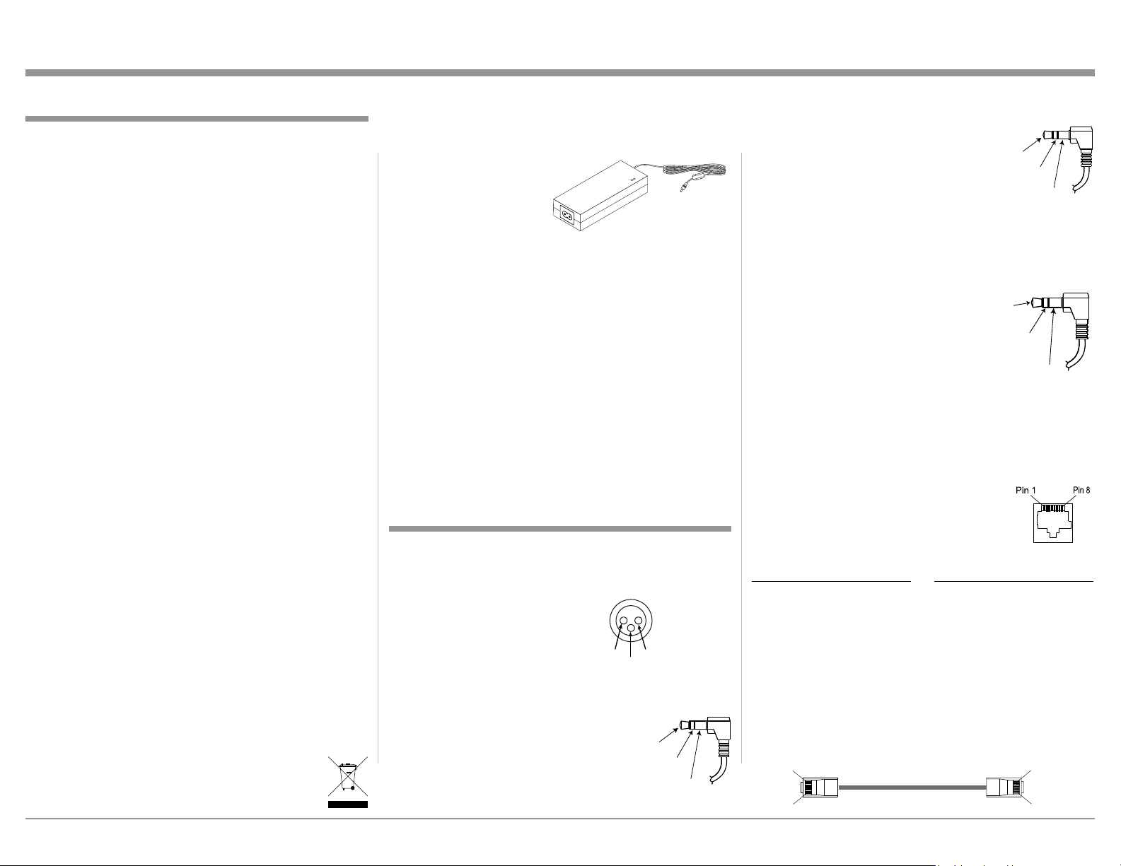
8. If it should become necessary to replace the supplied AC / DC Power
Adapter, order part
number 32059900
from the McIntosh
Parts Department.
9. For additional information on other McIntosh
Products please visit the McIntosh Web Site at
www.mcintoshlabs.com.
10. Mobile Device Apps for remote control operation
of the MS500, are available. Go to the McIntosh
Web Site at http://www.mcintoshlabs.com/us/Sup-
port/Pages/Manuals.aspx
Under “PRODUCT CATEGORY” select “Media
Streamers” then under “MODEL NUMBER”
select “MS500”. Click on “SEARCH” then click
on the MS500 Music Streamer App (iPhone, iPad
or Android) for your mobile device.
Connector and Cable Information
XLR Connectors
Below is the Pin configuration for the XLR Balanced
Output Connectors on the MS500. Refer to the diagram for connection:
PIN 1: Shield/Ground
PIN 2: + Output
PIN 1
PIN 3: - Output
Data and IR Input Port Connectors
The MS500 Data In Port receives Remote Control
Signals. A 3.5mm stereo mini phone
plug is used for connection. The IR
Ports also use a 3.5mm stereo mini
PIN 2
Data
Signal
N/C
Data
Ground
phone plug and allow the connection
of other brand IR Receivers to the
MS500.
IR Data
Control
N/C
Ground
Power Control Connector
The Power Control Input Jack receives Power On/
Off Signals (+12 volt/0 volt) when connected to other
McIntosh Components. The Power Control Output
Jack sends Power On/Off Signals (+12 volt/0 volt)
when connected to other McIntosh Components. An additional
connection is for controlling the
illumination of the Power Output Meters on McIntosh Power
Power
Control
Meter
Illumination
Control
Pass Thru
Ground
Amplifiers. A 3.5mm stereo mini phone plug is used
for connection to the Power Control Jacks.
Ethernet RJ45 Socket
1. Transmit Data (+) 5. N/C
2. Transmit Data (-) 6. Receive Data (-)
3. Receive Data (+) 7. N/C
4. N/C 8. N/C
Ethernet Cable - Straight Thru Connections
Pin Number - Wire Color Pin Number - Wire Color
1.Orange/White → 1.Orange/White
2.Orange → 2.Orange
3.Green/White → 3.Green/White
4.Blue → 4.Blue
5.Blue/White → 5.Blue/White
6.Green → 6.Green
7.Brown/White → 7.Brown/White
8.Brown → 8.Brown
Pin 1
Pin 8
3
Page 4

General Information, Cable Information, Disc Information, Introduction and Performance Features
Introduction
The McIntosh MS500 Music Streamer offers the latest
in audio technology, providing state of the art audio
reproduction with the convenience of instant access
to your music library. When the MS500 is added to a
McIntosh System, the music from this source may be
enjoyed in your home. The advanced design ensures
many years of smooth trouble free operation.
• Local AM/FM Radio Stations
The MS500 also allows for listening to AM/FM Stations via the Internet Connection.
• Select your Music
Listen to the music you want by creating your own
play lists and/or groups of music types.
• Quiet Fan Less Operation
Enjoy your music even at low system volume settings.
• Power Control
The Power Control Input connection provides convenient Turn-On/Off of the MS500 when connected to a
McIntosh System with Power Control.
Performance Features
• Built-in Networking Capability
The MS500 has the ability to connect to an existing
network for connecting to other devices also connected to the network, including the Internet (the Cloud).
• High Storage Capacity
The MS500 incorporates a massive 500 Gigabyte
Hard Drive capable of storing the contents of a large
Music Collection.
• Expand the Music Server System
The MS500 can provide seamless access to music
contained on other MS500(s) from different physical
locations. It can also access music stored on other devices such as Computers and NAS (Network Assisted
Storage) Devices connected to the same network as
the MS500. This provides for unlimited music storage
capacity.
• USB 3 and USB 2 Inputs
Connect external storage devices to the MS500 for
increased music storage capacity.
• Internet Streaming Services
The MS500 also allows for listening to Internet Stations when connected.
• Digital Audio Outputs
There is a Coaxial and an Optical Digital Audio Output (SPDIF) for connection to other components.
• Balanced and Unbalanced Analog Outputs
The MS500 has both Unbalanced Outputs and Balanced Outputs which permit long cable lengths without a loss in sound quality.
• Graphical User Interface
When connected to a TV/Monitor, the On Screen
Display provides information such as Album Name,
Artist Name, Song Name, Playing Time and Location
for each of the selections. This allows for easy song
selection from multiple rooms in your home.
• HD Video Outputs
The MS500 has HDMI and VGA Connections for
providing High Definition Video Signals of 1080p or
720p resolutions.
• On Screen Setup
The On Screen Setup allows for customizing various
settings such as audio, video, network and external
control to match the components in your system.
• Remote Control
The Remote Control with illuminated push-buttons,
provides control of the MS500 operating functions. A
Data Port Connection to a McIntosh A/V Processor or
Preamplifier allows for convenient system operation
using one Remote Control. An External IR Sensor
Input allows for remote operation when the MS500 is
located behind closed doors.
• Illuminated Glass Front Panel
The famous McIntosh Glass Front Panel is evenly
illuminated by multiple extra long life Light Emitting
Diodes (LEDs), arranged with a special orientation.
The pristine beauty of the MS500 will be retained for
many years.
4
Page 5
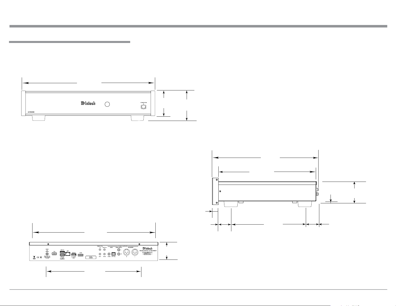
Dimensions
The following dimensions can assist in determining
the best location for your MS500.
Front View of the MS500
17-
1/2"
44.5cm
Dimensions
MS500 MUSIC STREAMER
Rear View of the MS500
17-1/32"
43.3cm
3-9/32"
8.3cm
3-7/8"
9.8cm
29/32
1.8cm
1-5/8"
4.1cm
Side View of the MS500
13"
33.0cm
12-1/16"
30.6cm
2-11/32"
6.0cm
2-17/32"
6.4cm
"
9-1/16"
23.0cm
1-3/8"
3.5cm
13-1/4"
33.7cm
2-11/32"
6.0cm
5
Page 6
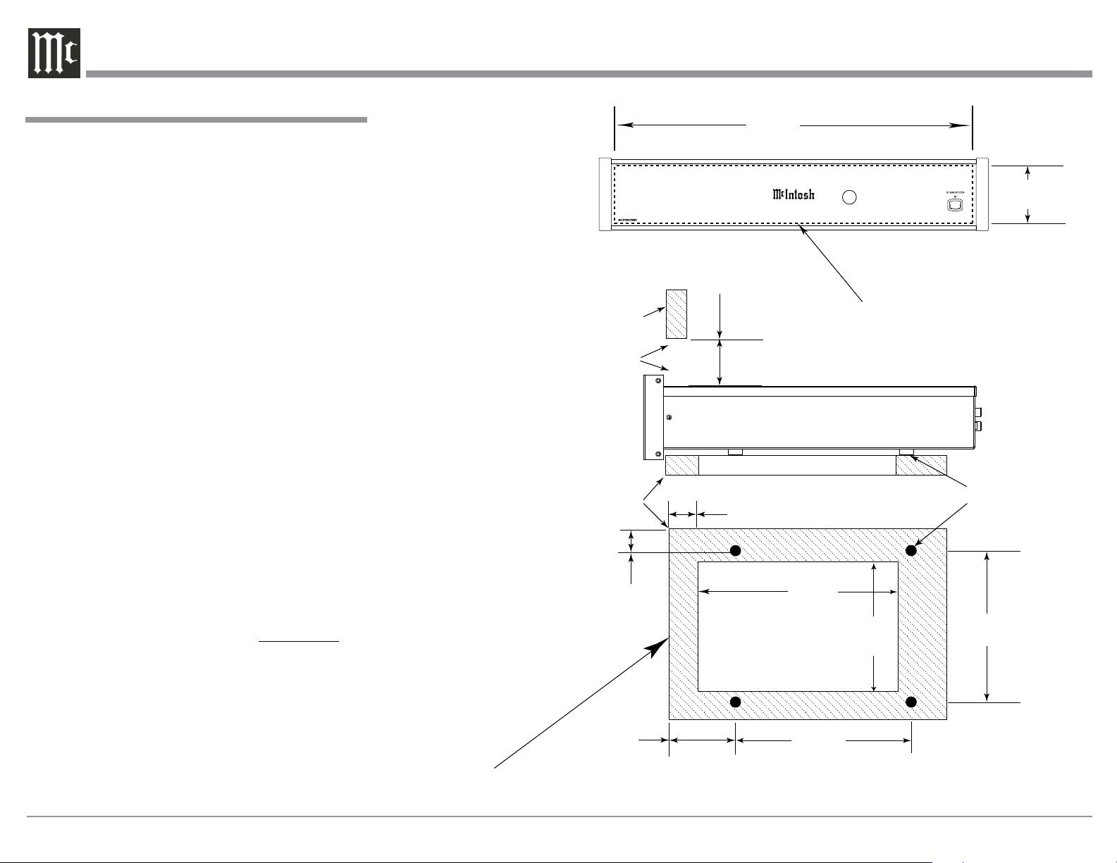
Installation
Installation
The MS500 can be placed upright on a table or
shelf, standing on its four feet. It also can be custom
installed in a piece of furniture or cabinet of your
choice. The four feet may be removed from the bottom
of the MS500 when it is custom installed as outlined
below. The four feet together with the mounting
screws should be retained for possible future use if the
MS500 is removed from the custom installation and
used free standing. The required panel cutout, ventilation cutout and unit dimensions are shown.
Always provide adequate ventilation for your
MS500. Cool operation ensures the longest possible
operating life for any electronic instrument. Do not
install the MS500 directly above a heat generating
component such as a high powered amplifier. If all
the components are installed in a single cabinet, a
quiet running ventilation fan can be a definite asset in
maintaining all the system components at the coolest
possible operating temperature.
A custom cabinet installation should provide the
following minimum spacing dimensions for cool
operation.
Allow at least 3 inches (7.6cm) above the top, 2
inches (5.1cm) below the bottom and 1 inch (2.5cm)
on each side of the Music Streamer, so that airflow is
not obstructed. Allow 17 inches (43.2cm) depth behind
the front panel. Allow 29/32 of an inch (1.8cm) in
front of the front panel for clearance. Do not block the
openings on the top cover or the three rows of louvers
opening on the bottom of the MS500. Be sure to cut
out a ventilation hole in the mounting shelf according
to the dimensions in the drawing.
MS500 Front Panel
Custom Cabinet Cutout
MS500 Side View
in Custom Cabinet
MS500 Bottom View
in Custom Cabinet
Cabinet
Front
Panel
Opening
for Ventilation
Support
Shelf
2-19/32"
6.6cm
2-27/32"
7.2cm
3"
7.6cm
13/16"
2.0cm
Cutout Opening
for Ventilation
17-1/8"
43.5cm
MS500 MUSIC STREAMER
Cutout Opening for Custom Mounting
Cutout Opening for Ventilation
10-1/2"
26.7cm
11-7/8"
30.2cm
6-9/16"
16.7cm
2-3/4"
7.0cm
Chassis
Spacers
14-17/32"
44.5cm
Note: Center the cutout Horizontally on the unit.
For purposes of clarity, the above
illustration is not drawn to scale.
6
Page 7
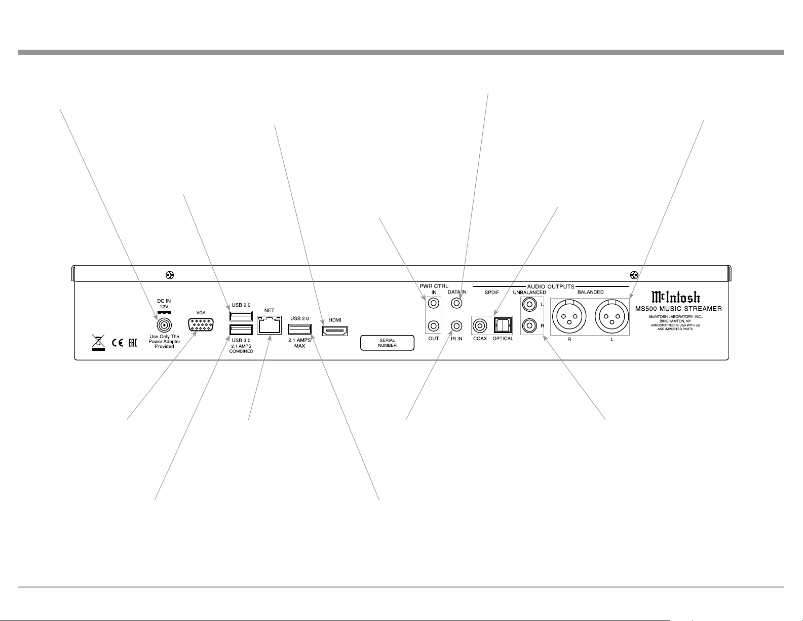
Rear Panel Connections
Connect the supplied
AC/DC Power Adapter
DC Output Connnector
USB (version 2.0)
an external storage device capable
of transferring data
HDMI (High-Definition Multimedia Interface) Output (Audio and Video Digital Signals) for connecting to a HDTV or Monitor
with a HDMI Input with a video resolution
720p or 1080p
1
for connection of
PWR CTRL (Power Control) IN receives turn-on signals from a McIntosh component and POWER CONTROL OUT sends turn-on signals on
to another McIntosh Component
DATA IN receives control data
from a McIntosh Control Center
COAXial and OPTICAL AUDIO OUTPUTS
send a Digital Audio Signal to a Preamplifier
or an A/V Control Center with a D/A Converter or a decoder
BALANCED AUDIO OUTPUTS
supply analog audio signals to
connect to Balanced Inputs of
other components
VGA (Video Graphics Array) Analog Video Output for connecting to
a TV or Monitor with a VGA Input
1
USB (version 3.0)
for connection of
an external storage device capable
of transferring data at high speed
NETwork Connector for
connecting the MS500 to a
Broadband Ethernet Network
IR IN for connecting
an IR Receiver
USB (version 2.0)1 for connection of
an external storage device capable
of transferring data
UNBALANCED AUDIO
OUTPUTS supply analog audio
signals to Unbalanced Inputs of
other components
1
One at a time, of the three USB Connectors on the MS500 has
the ability to output Digtal Audio Signal for music playback to
an external audio device compatible with USB current operational standards
7
Page 8
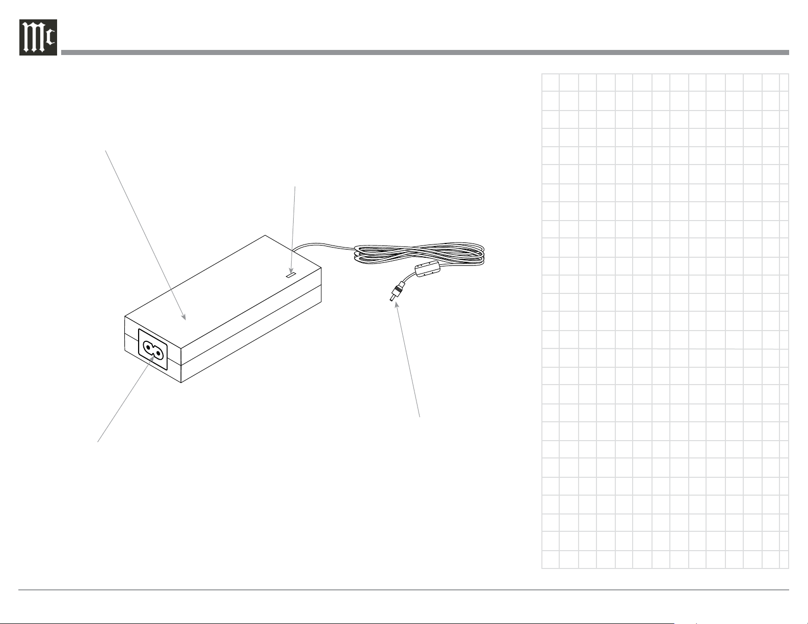
The AC/DC Power Adapter supplied
with the MS500 Music Streamer
Connect to a live AC outlet (always On)
using the supplied AC Power Cord. Refer to information on the power supply
to determine the correct voltage.
AC/DC Adapter power
On LED Indicator
Connect to the DC IN connector on
the Rear Panel of the MS500 Music
Streamer
8
Page 9

AC/DC Adapter Connections and Notes
9
Page 10

MS500 Connections
The MS500 has the ability to be remotely switched
On/Off from a McIntosh Preamplifier or A/V Processor via the Power Control connection. The MS500
Data Port Connection allows for the remote operation
of basic functions using the Preamplifier, Integrated
Amplifier or A/V Control Center Remote Control.
With an external sensor connected to the MS500, remote control operation is possible from another room
and/or when the MS500 is located in a cabinet with
the doors closed.
The connection instructions below together with
the MS500 Connection Diagram on the next page is
an example of a typical audio or audio/video system.
Your system may vary from this, however the actual
components would be connected in a similar manner.
For additional information refer to “Connector and
Cable Information” on page 3.
Power Control Connections:
1. Connect a Control Cable from the Preamplifier,
Integrated Amplifier or A/V Processor Power
Control MAIN (or ACC) Jack to the PWR CTRL
(Power Control) IN Jack on the McIntosh MS500
Music Streamer.
2. Optionally, connect a Control Cable from the
MS500 Music Streamer PWR CTRL OUT Jack to
another component.
3. Connect any additional components in a similar
manner, as outlined in steps 1 thru 3.
Data Control Connections:
4. Connect a Control Cable from the Preamplifier,
Integrated Amplifier or A/V Processor Data Port
1 Jack to the McIntosh MS500 Music Streamer
DATA IN Jack.
Sensor Connections:
5. Optionally, connect an IR Sensor to the McIntosh
MS500 Music Streamer IR IN Jack.
Digital Audio Connections:
6. Optionally, connect a Cable from the McIntosh
MS500 Music Streamer AUDIO OUTPUT SPDIF
OPTICAL Output to the Digital Audio Input Optical 1 Input on the Preamplifier, Integrated Amplifier or A/V Processor.
Note: Coaxial connections may be used instead of
the Optical Connections.
Analog Audio Connections:
7. Connect a Cable from the McIntosh MS500 Music
Streamer AUDIO OUTPUT BALANCED connectors to the Preamplifier, Integrated Amplifier or
A/V Processor Balanced 1 Input connectors.
Note: Unbalanced connections may be used instead
of the Balanced Connections.
Digital Video Connections:
8. Connect a HDMI Cable between the HDMI Socket
on the Rear Panel of the MS500 Music Streamer to
a HDMI Input Socket on the HD Monitor/TV.
Notes: 1. If the Monitor/TV has a VGA Input and
no HDMI input, then connect a VGA
cable between the MS500 and the Monitor/ T V.
2. The MS500 HDMI Output Socket
provides Video Signals only. For Audio
Signal Playback, perform connections in
step 6 or 7.
Network Connections:
9. Using a CAT 5/6 Ethernet Cable, connect the cable
from the Router to the NET (Network) connector
on the Rear Panel of the MS500.
10. Optionally, connect another CAT 5/6 Ethernet
Cable from the Computer (Network Connector) to
the Router.
Note: For additional information on Networks and
Network Connections refer to the documentation supplied with the Router and Computer.
AC Power Cords Connections:
11. Locate the plug at the end of the cable coming out
of the supplied AC/DC Power Supply and connect
it to the DC Input connector on the Rear Panel of
the MS500 Music Streamer.
12. Connect the supplied AC Power Cord between the
socket on the AC/DC Power Supply and a live AC
outlet (that is always On).
10
Page 11

MS500 Connections
Optional Computer
Network Router
(Wireless or Wired)
Preamplier
Connect to a
live AC Outlet
(alway s On)
MS500 supplied
AC/ DC
Power Supply
Connect to a
live AC Outlet
(alway s On)
(optional Digital Audio Connection)
HD Monitor/TV
IR Sensor
11
Page 12

Front Panel Display and Push-button
IR Sensor receives commands
from a Remote Control
12
MS500 MUSIC STREAMER
STANDBY/ON Push-button with indicator
switches the MS500 ON or OFF (Standby)
and resets the microprocessors
Page 13

How to use the Remote Control
The Remote Control is capable of performing most
Operating Functions for the MS500 Music Streamer.
Note: Refer to the “How to Operate” Section of this
manual for additional information using this
Remote Control.
Dual Function Push-buttons
The five push-buttons located at the top/front of the
Remote Control, in the circular molded area, are dual
function. When music is playing, the (+) Push-button
increases the volume level
decreases the volume level
for the next selection or push the 9 Push-button for
the previous selection.
During the time a MS500 Menu is being accessed, the push-buttons at the top/front of the Remote
Control provide the ability to navigate the menus and
select the desired choice or function. The (+) Push-button is used to move the cursor Up through the menu.
Likewise, the (-) Push-button is used to move Down.
The 9 Push-button is used to move to the Left, the :
Push-button is used to move to the Right and the ►
Push-button is used to Select the highlighted choice.
1
and the (-) Push-button
1.
Push the : Push-button
SELECTS the current menu item and
also starts playback
and pauses playback
Selects the previous
selection
Decreases the
volume level
Current selection
is liked
Selects a Menu
How to use the Remote Control
Directional Push-buttons; Ê (Up),▬(Down),
9 (Left), : (Right)and►(SELECTS)
Increases the
volume level
Selects the next
selection
Momentarily
press to Power the
MS500 ON or OFF
Indicates when a
Remote Control
Command has been
sent
Current selection
is disliked
1
Adjusting the volume level using the Remote Control requires a change to the default setting located
in the Setup Mode, refer to pages 14 and 15 for additional information.
Selects available
information
Reserved for
future use
Moves forward in time
through a selection
13
Page 14

How to Operate the Setup Mode
The McIntosh MS500 is factory configured for immediate enjoyment of superb audio. If you wish to make
changes to the factory default settings, a Setup Feature
is provided to customize the operating settings using a
PC Computer (not supplied) and with the MS500 connected to a HD Monitor/TV. Start the Setup Mode by
performing the following steps:
1. Press the MS500 Front Panel STANDBY/ON
Push-button or press the (Power) Push-button
on the Remote Control to switch On the MS500.
Refer to page 13 for information on using the
Remote Control. The LED above the STANDBY/
ON Push-button will illuminate. The MS500 will
go through a startup initialization which might
take upwards of 1.5 minutes with it connected to a
HD Monitor/TV indicating the progress. Refer to
figures 1 and 2.
IP Address location
Figu re 3
Note: If the “Server IP Address” number appears
as 0.0.0.0, the MS500 was unable to obtain an
IP Address from the computer network. Power
down the MS500, wait several minutes and then
Switch it back On. If the MS500 is still unable
to obtain an IP Address, the default automatic
configuration setting (DHCP, Dynamic Host
Configuration Protocol) might have to be set
manually. Contact your Computer Dealer or
the Computer Manufacture for assistance.
3. Using a computer connected to the same network
as the MS500, launch the Internet Web Browser
Application and type in on the “URL-Address
line”, the following:
The IP Address Number written down in step 2
Figu re 1
Figu re 2
2. When the initialization is completed, the operational screen will appear and in the upper left corner is the “Server IP Address: _ _ . _ _. __ _. _ _ _.
Write down the IP Address Number, as it will be
used in the next step. Refer to figure 3.
14
HTTP://__._ _.___.___/config
Then press Enter on the computer keyboard. Refer to
figure S1. The Setup Tabs at the top of the window:
Setup Option Tabs Figure Number
Server Settings S1
Display Settings S2
Source Settings S3
Content S4
Schedule S5
Firmware S6
Figure S1
Page 15

Each of the tabs has subheadings with current settings
status information along with various setup options.
There are explanations located to the right of the various options and settings.
4. Select “Display Settings”. Refer to figure S2.
5. To change the “Screen Resolution” from the defaut
setting of 720p to 1080p, click on the circle ahead
of “ 1080p 1920x1080”.
6. To implement the Setup change just made, Click
on the Display Settings Button “Save Changes”.
Then press the MS500 Front Panel STANDBY/ON
Push-button or press the (Power) Push-button
on the Remote Control to switch OFF the MS500.
7. Press the Front Panel STANDBY/ON Push-button
or press the (Power) Push-button on the Remote
Control to switch ON the MS500.
8. After any other changes have been made and
saved, proceed to “How to Operate” starting on
page 16.
Setup
Figu re S5
Figu re S3
Figu re S2
Figu re S6
Figu re S4
15
Page 16

How to Operate the MS500
Power On and Off
Your McIntosh MS500 has been factory configured
for default operating settings that will allow immediate enjoyment of superb audio without the need for
further adjustments. To make changes to the default
settings, refer to the Setup Mode on page 14.
1. Press the STANDBY/ON Push-button on the Front
Panel or press the (Power) Push-button on the
Remote Control to switch On the
MS500. Refer to figures 5, 6 and 7.
The LED above the STANDBY/ON
Push-button will start flashing during the MS500 startup initialization
process, which might take upwards
of 30 seconds. The HD
Monitor/TV connected to
the MS500 will indicate
the startup initialization
procedure progress. Refer
to figures 8, 9 and 10.
2. To switch Off the MS500,
press the STA N DBY/
ON Push-button on the
Front Panel or press the
(Power) Push-button on
the Remote Control. Refer
to figures 5 and 6.
Figu re 5
Figu re 6
Figu re 8
Figu re 9
Fig u re 10
Start Music Playback
Music was imported into the MS500 Music Streamer,
at the factory, for your enjoyment. To start listening to
the music, perform the following:
1. Press the (MENU) Push-button on the Remote
Control to select the Operation Menu. Then using
the ▬ (Down) Push-button on the Remote Control, select the “Music Menu” followed by pressing
the
► (SELECT) Push-button to select “Album
Menu”. Refer to figures 11 and 12.
2. Press the ► (SELECT) Push-button on the Remote Control to view the available Albums. Refer
to figure 13.
Fi g u re 11
Figu re 12
Figure 13
16
MS500 MUSIC STREAMER
Figu re 7
3. Use the
Ê (Up) or ▬ (Down) Push-button on
the Remote Control to select the desired album. In this instance, select “Various Artists Beethoven:Symphonies Nos. 5&9 Choral; Piano
Concert”. Then press the
► (SELECT) Push-
button to select the album. Refer to figure 14.
Page 17

How to Operate the MS500
Figure 14
4. Referring to figure 15, the track for the album just
selected will appear. In this instance there is one
track “ Symphony No. 9 (Scherzo)”. Press the
►
(SELECT) Push-button on the Remote Control to
start playback of the first track. Refer to figure 16.
Fig ure 15
Figure 16
The TV/Monitor will start to display various scenes
while the music is playing. Refer to figures 17 and 18.
5. To pause playback of the music, press the ► (SE-
LECT) Push-button on the Remote Control. To
resume playback, just press the same Push-button
again. To see the status of the track currently playing, press the MENU Push-button and refer to
information located at the bottom of the screen.
Refer to figure 15 and 16.
Fig u r e 17
Figure 18
How to Stream Music
The MS500 Music Streamer provides access to virtually unlimited music by streaming music from the
Internet. To start streaming music from the Internet,
perform the following:
1. Press the (MENU) Push-button on the Remote Control to select the Home Menu. Refer to
figu r e 19.
Figure 19
2. Press the ► (SELECTS) Push-button on the
Remote Control to select the “Streaming Menu”.
Refer to figure 20.
Figu re 20
There are many pre-setup Internet Radio Sites to
choose from, including Deezer, Murfie, Pandora Internet Radio, SiriusXM Internet Radio, Slacker Radio,
Spotify, TIDAL, etc. Some Internet Radio Sites require registering and in some instances a subscription
fee in order to enjoy their music services. Using the
MS500 Setup Mode on pages 14 and 15, refer to the
Contents tab and then the Online Credentials for additional information. In the following example, TuneIn
Radio will be selected to stream music from local FM/
AM radio stations.
3. Using the Ê (Up) or ▬ (Down) Push-button on
the Remote Control, select TuneIn Radio from the
menu. Refer to figure 21.
Fig u r e 21
4. Refer to figure 22 on the next page, then press
the ► (SELECTS) Push-button to select Local
Radio.
17
Page 18

How to Operate the MS500, con’t
Figu re 22
5. There are now menu choices AM, FM or Internet
only radio stations. Referring to figure 23, use
the Ê (Up) or or ▬ (Down) Push-button to select
FM, followed by pressing the the ► (SELECTS)
Push-button.
Figu re 23
6. Referring to figure 24, it follows the same procedure as in step 5, select the fourth choice, “89.3
WSKG-FM (Classical Music)”. The sound from
the station will start, refer to figure 25.
Figu re 24
Figu re 25
How to Operate the MS500 via a Computer
After the MS500 has powered up and completed
initialization, the IP Address assigned to the Music
Streamer will appear in the upper left corner. Refer to
figure 26.
IP Address Location
Figu re 26
1. Using a computer connected to the same network
as the MS500, launch an Internet Web Browser
Application (such as Windows Internet Explorer).
Type in on the “URL-Address line” the following:
The IP Address Number
HTTP://__._ _.___.___/MediaBridge
2. A connection progress indicator will appear in the
Web Browser. Refer to figure 27.
3. When the connecting process is completed, theMusic Streamer interface will appear in the Web
Browser. Refer to figure 28.
Figu re 27
Figu re 28
Note: The operation of the MS500 using the Web
Browser is similar to using the MS500 connected to a monitor/TV along with the supplied
Remote Control. The major difference is the
computer pointing device (mouse) is used for
selection and navigation.
On the left side is a column of buttons for selecting music sources (Streaming, Local Music, Favorites,
Playlists and Queue) along with Back and Next control
commands. Along the bottom are buttons for standard
control functions such as Previous, Play, Pause, Next,
Shuff le and Replay.
18
Page 19

How to Operate the MS500, con’t
How to Playback Music
McIntosh Music was imported into the MS500, at the
factory, for your enjoyment. To start listening to the
music, perform the following:
1. Click on the Local Music button. Refer to
figure 28.
2. Click on “Albums”, then select “Beethoven”. Refer
to figure 29.
Figu re 29
3. Click on the track listing of “1 Symphony No. 9
(Scherzo) 1:15” and click on “Play now”. Refer to
figures 29 and 30.
How to Stream Music
The MS500 Music Streamer provides access to virually unlimited music by streaming music from the
Internet. To start streaming music from the Internet,
perform the following:
1. Click on the Streaming button and the Radio
sources menu will appear. Refer to figure 31.
Fig u r e 31
In the following example TuneIn Radio will be selected to stream music from local FM/AM radio stations.
2. Select and click on TuneIn Radio. Click on Local
Radio followed by selecting FM. Refer to figures
32 and 33.
3. Referring to figure 34, select the second choice,
“89.3 WSKG-FM (classical)”. The sound from the
station will start and figure 35 will appear.
Figure 34
Figure 35
Figu re 30
4. Return to the previous menu selection of “Play
now, Play next, Replace queue, Add to queue or
Add to playlist” by clicking on the Track (Name)
currently playing.
Figure 32
Figure 33
19
Page 20

How to Operate the MS500, con’t
Using External Drives with the MS500
The MS500 has three different uses for connected
External Drives “ADD, IMPORT or MOUNT”. Before
proceeding with the steps below, switch power Off to
the MS500. Then connect the External Drive (HDD,
SDD or USB Flash Memory) to an USB connector on
the Rear Panel of the MS500. After the MS500 has
powered up and completed initialization, note the IP
Address in the upper left corner.
1. Using a computer connected to the same network
as the MS500, launch an Internet Web Browser
Application (such as Windows Internet Explorer).
Type in on the “URL-Address line” the following:
Three operational
options available for
MS500 Internal Drive
Name assigned to
the connected
External USB Drive
Figure 37
the connected
External USB Drive
to activate the chosen choice. Refer to figures 38,
39 and 40
ADD External Storage Space to the MS500
With an Externa1 USB Drive connected to one of the
MS500 Rear Panel USB Connectors, the “ADD” option will become available.
Note: Do not remove the external drive after the
“ADD” option is activated.
1. Start the ADD process by clicking on the button
“OK, Add the volume”. Refer to figure 38 and then
fig u re 41.
The IP Address Number
HTTP://__._ _.___.___/config
2. Then press enter on the computer keyboard. Refer
to figure 36 (partial view).
Content Tab
Figure 36 (partial view)
3. Click on the “Content” Tab (located along the
top), then scroll down to “Storage”. Referring to
figure 37, the three options for the external USB
Connected Drive appears next to the “Free” Space
Listing. The option choices include “ADD, IMPORT or MOUNT”. When any one three choices
are selected, a new window will appear explaining
the functioning, any possible limitations and “OK”
Figu re 38
Figure 39
Figu re 40
Figure 41
2. When the external drive is to be removed from
the MS500, select “Remove from server” and then
start the remove process by clicking on the button
“OK, Remove the volume”. Refer to figures 42
and 43.
Figu re 42
Figure 43
20
Page 21

How to Operate the MS500, con’t
IMPORT Music to the MS500
With an Externa1 USB Drive connected to one of the
MS500 Rear Panel USB Connectors, the “IMPORT”
option will become available.
1. Start the Import process by clicking on the button “OK, Import the volume” (Figure 39). During
the “Import” functioning, various messages will
appear in the window indication the “Importing
status”. Refer to figure 41, 42 and 43.
Note: After an external drive is connected to the
MS500 and the “ADD” option is activated it
can not be disconnected until after the import
process copies all of the music files it finds on
the externally connected storage drive. Depending on the amount of music files on the
drive, the copying process could take some
time.
2. Start the import process by clicking on the button “OK, Import the volume”. Refer to figures 44
and 45.
MOUNT External Storage Drive to the MS500
With an Externa1 USB Drive connected to one of the
MS500 Rear Panel USB Connectors the “MOUNT”
option will become available.
1. Start the Mount process by clicking on the button
“OK, Mount the volume” (Figure 40). During the
“Mount” functioning, various messages will appear in the window indication the “Mount status”.
Refer to figure 46.
Note: Do not remove the external drive after the
“Mount” option is activated.
Figure 46
2. If when the external drive is to be removed from
the MS500, select “Unmount”. Refer to figure 47.
Figu re 44
Figure 45
3. Then select local music, click on albums, and select
the music just Imported into the MS500.
Figure 47
21
Page 22

How to Operate the MS500, con’t
Using the McIntosh Media Sync Program
The McIntosh Media Sync Computer Program allows
you to select music that is stored on your computer(s)
and other components that are also connected to the
same computer network as the McIntosh MS500
Music Streamer. The program will automatically copy
the selected music onto the MS500. After the music
is copied on to the MS500, it will also automatically
remove it from the MS500 after the music is removed
the from the computer(s) and the other components on
the computer network. Perform the following steps to
install the McIntosh Media Sync for Windows:
Notes: 1. If your computer is an Apple Mac unit, the
McIntosh Media Sync for Mac can be installed instead.
2. The McIntosh Media Sync Program is designed to work on a Home Computer Network
System.
1. Using your computer connected to the same
network as the MS500, launch an Internet Web
Browser Application (such as Windows Internet
Explorer). Type in on the “URL-Address line” the
following:
The IP Address Number
HTTP://__._ _.___.___/config
2. Then press enter on the computer keyboard. Refer
to figure 48 (partial view).
Content Tab
Figure 48 (partial view)
3. Click on the “Content” Tab (located along the top),
then scroll down to “Media Synchronization”.
Referring to figure 49,
Figu re 49
4. Select “Install McIntosh Media Sync for Windows”.
5. A small window appears at the bottom of the
screen, then click on the “Run” button to start the
installation of the
MediaSyncSetup.exe
Program. Refer to
figures 49 thru 55.
6. When figure 55 ap-
Figure 50
pears on the screen, click on the “Finish” button
to start the just installed McIntosh Media Sync
Program.
Note: To start the McIntosh Media Sync Program,
select hidden icons and click on the icon. Refer
to figure 56.
Fig ur e 51
Figure 53
Fig ure 55
Figure 52
Figu re 54
Click to Start
the Program
Figu re 56
Once the McIntosh Media Sync Program is installed
on the computer and has been started, there are some
additional functions that need to be completed for
actual operational functioning for your computer network system that the MS500 is connected to. Perform
the following steps:
7. Currently on the Computer Screen the STATUS
Tab should be displayed. Refer to figure 57.
8. In the top pull down window, the display should
22
Page 23

How to Operate the MS500, con’t
be indicating “MediaBridge1 -Media
Control Server on
MediaBridge 1
(IP address). The
IP Address is the
current MS500 IP
Address as displayed in the upper
left corner on TV/
Monitor the MS500
is connected to.
9. If the Server IP
Address needs to
be changed, select
the top pull down
window▼and
then select the “Add
Server”. Refer to
figure 58.
10. Add in the new IP
Address in the “Add
Server” window and
then click on “Add
Server”. Refer to
figu r e 59.
11. After the IP Address
settings have been
completed, click on
the “iTunes” Tab for
the iTunes Music
Settings. Refer to
figure 60.
Note: If there is no
iTunes Library Music on your computer the
“iTunes Tab” will be replaced by a grayed out
Figure 57
Figu re 58
Figure 59
Figure 60
“iTunes (Missing Library)” Tab.
12. After selecting the “iTunes Tab”, click on the
“Automatically update iTunes music”
and the “Update all
Music and Playlists”. Then select
the desired “Playlists” and the Music
Catagory(s) appearing in the white
Figure 61
window. Refer to
figu r e 61.
Note: To prevent
deleting Music
unintentionally, please
ensure iTunes
is sharing this
Librar y.
Figu re 62
13. Refering to figures
62 and 63, select
the “OTHER Tab”
to add other (noniTunes) music on the
computer (or from
other components
connected the to
same Network as
Figu re 63
the MS500). To add
Folders that contain
Music, click the
“+” button and then
select the desired
Folder containing
the music you want
the MS500 to be able
Figu re 64
to playback. To add
more folders repeat
the same procedure.
When all the folders
have been selected,
click on the “Apply
Changes” button to
start the the process
Figu re 65
of copying the selected music track onto the MS500. Refer to figure
64.
14. Referring to figure 65, select the “Advanced Tab”
which has “Server Information”, “Advanced Server
Functions” and “Options”.
By default the McIntosh Media Sync Computer
Program starts up every time the computer it is
installed on is switched On and the program operates in the background. It automatically maintains
synchronization of the music tracks on the MS500
that were copied from the computer(s) and the
other components on the network that the MS500
is connected to.
If you do not want the McIntosh Media Sync Com-
puter Program to automatically maintain synchronization of the music tracks, uncheck the “OPTIONS: Start at login”. This prevents the copying
and/or deleting music tracks on the MS500 that are
or were from the computer and the other components on the computer network. You can then
perform the copying and/or deleting music tracks
on the MS500 by manually starting the McIntosh
Media Sync Computer Program.
Refer to figure 56.
23
Page 24

24
Page 25

Photos
25
Page 26

Specications
Audio Specifications
Fixed Output Level
2.0Vrms Unbalanced
4.0Vrms Balanced
Output Impedance
600 ohms Unbalanced and Balanced
Signal to Noise Ratio
102dB (IHF A-Weighted)
Dynamic Range
96dB
Harmonic Distortion
0.005%
Channel Separation
95dB (1,000Hz)
Digital Audio Specifications
Digital Output
Coaxial: 0.5V p-p/75 ohms
Optical: - 15dbm to -21dbm (TOS Link)
Video Specications
Signal System
Digital Video
Signal Format
HDMI and VGA
Screen Resolution
720p or 1080p
Power Control Specications
Power Control Input
5-15VDC, less than 1mA
Power Control Output
12VDC, 25mA maximum total
General Specifications
Power Requirements
Field AC Voltage conversion of the MS500 is not
possible. The MS500 is factory configured for following AC Voltages:
100-240 Volts, 50/60Hz at 2.0 Amps
Standby: Less than 0.5 watt
Overall Dimensions
Width is 17-1/2 inches (44.4cm)
Height is 3-7/8 inches (9.8cm)
Depth is 16 inches (40.6cm) including the Front Panel
and connection cables.
Weight
13.5 pounds (6.1Kg) net (includes the external Power
Supply), 28 pounds (12.7Kg) in shipping carton
Shipping Carton Dimensions
Width is 26-1/2 inches (67.3cm)
Height is 11-3/4 inches (29.9cm)
Depth is 24-1/4 inches (62.2cm)
Digital Output Format
SPDIF (PCM1)
Digital Output Sample Rate
Up to 24-Bit/192kHz
1
PCM (Pulse Code Modulation) Digital Signal Type
26
Page 27

Packing Instructions
In the event it is necessary to repack the equipment for
shipment, the equipment must be packed exactly as
shown below. It is very important that the four plastic feet are attached to the bottom of the equipment.
This will ensure the proper equipment location on the
bottom pad. Failure to do this will result in shipping
damage.
Use the original shipping carton and interior parts
only if they are all in good serviceable condition. If
a shipping carton or any of the interior part(s) are
needed, please call or write Customer Service Department of McIntosh Laboratory. Refer to page 4. Please
see the Part List for the correct part numbers.
Quantity Part Number Description
1 033838 Shipping carton only
4 033837 End cap
1 033836 Inside carton only
1 033725 Top pad
1 034576 Bottom pad
1 034547 Bottom filler pad
2 034446 Foam plug
Packing Instructions
MODEL NO.
POWER
SUPPLY
POWER SUPPLY
CARTON
4 017937 Plastic foot
4 400159 #10-32 x 3/4” screw
4 404080 #10 Flat washer
27
Page 28

McIntosh Laboratory, Inc.
2 Chambers Street
Binghamton, NY 13903
www.mcintoshlabs.com
The continuous improvement of its products is the policy of McIntosh Laboratory Incorporated who reserve the right to
improve design without notice.
The MS500 is designed to employ non-McIntosh-provided services (including but not limited to Spotify, Tidal,
Pandora, SiriusXM and Napster), some of which require separate customer subscriptions and some of which do not,
as part of the Products’ functionality. Because McIntosh cannot control the providers of such services or the services
themselves, the owner of the Product therefore assumes all risks related to the use of services provided by anyone other
than McIntosh itself. McIntosh cannot and does not warrant against, and shall have no liability of any kind for any
of the following that are attributable to non-McIntosh providers or services: (i) interruption, discontinuance, or other
unsatisfactory performance of service; (ii) reduced Product functionality that is so attributable; or (iii) any other loss or
damage of any kind that is so attributable.
Printed in the U.S.A.
McIntosh Part No. 04173401
 Loading...